
Removing the unit
Extracción de la unidad
' ¤ł¥»
Installation/Connections
Instalación/Conexiones
ƒw‚¸¡ ‰u‚ ⁄§‡s–
FM/AM
Cassette Car
Stereo
3-868-316-31 (2)
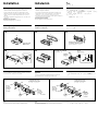
Parts for installation and connections
Componentes de montaje y conexiones
ƒw‚¸⁄˛‰u‚ ‡s– ¥˛“”„s¥
The numbers in the list are keyed to those in the instructions.
Los números de la lista corresponden a los de las instrucciones.
⁄U›–„ˇ“ ‚ “”‚„‰X'M»¡'œ⁄ ⁄⁄“”‚„‰X‹ ƒP¡C
XR-1100
Sony Corporation 2000
1
7
4
Caution
Cautionary notice for handling the bracket 1.
Handle the bracket carefully to avoid injuring your
fingers.
Precaución
Advertencia sobre la manipulación del soporte 1.
Tenga mucho cuidado al manipular el soporte para
evitar posibles lesiones en los dedos.
“‘•N
† ˚‚¸¤ł⁄ ‹[ 1 fi ¡A‰—flS§O“‘•N§O¶¸¤⁄«¡C
Note
The tool 8 is used for removing the unit.
Be sure to keep it for future use.
Nota
La herramienta 8 se utiliza para extraer la unidad.
Asegúrese de conservarla para poder extraer la unidad.
ø
⁄u¤ª 8 ¥˛§@' ¤ł¥» ¡C
¨¥†§· ‰«Oƒs¥»⁄u¤ª¥H‡˘⁄ «Æ' ¤ł¥» ⁄§¥˛¡C
2
8
5
× 2
3
6
× 4
1
1
Insert the supplied tool 8 between the unit and the frame, and rotate 90º to release the
hidden mounting spring. Repeat on the opposite side and remove the frame.
Inserte la herramienta 8 suministrada entre la unidad y el marco, y gire 90º para soltar el
resorte de montaje oculto. Repita esta operación en el lado opuesto y extraiga el marco.
–N·£¤ “”⁄u¤ª 8 ·¡⁄J¥» 'M fi ⁄§¶¡¡A¤ˆ– ´ 90º ¥H‚ £` ´ˆ“”ƒw‚¸…u´fiƒ'¡Cƒb‹ „ ‡“”¥t
⁄@ˆ ›«‰˘⁄W›z §@¡A M«Æ' ⁄U fi ¡C
10mm
90¢X
2
Insert a flathead screwdriver between the bracket and mounting spring. Gently pry the
spring toward the unit while pulling the unit out a little. Repeat on the opposite side and
remove the unit.
Inserte un destornillador de cabeza perdida entre la abrazadera y el resorte de montaje.
Haga palanca suavemente en el resorte hacia la unidad, mientras tira ligeramente de la
unidad al mismo tiempo. Repita esta operación en el lado opuesto y extraiga la unidad.
–N¥› Y`‡ •⁄M·¡⁄J⁄ ‹['Mƒw‚¸…u´fiƒ'⁄§¶¡¡Cƒb–N¥» y•L' ¥Xfi ¡A–N…u´fiƒ'·´¥» ¯Ø⁄Ł›–»·
»·… _¡Cƒb‹ „ ‡“”¥t⁄@ˆ ›«‰˘⁄W›z §@¡A M«Æ' ⁄U¥» ¡C
4mm
8

182 mm
53 mm
Installation
Precautions
•Choose the installing location carefully so that the unit will not
interfere with the normal driving functions of the driver.
•Avoid installing the unit where it would be subject to high
temperatures, such as from direct sunlight or hot air from the
heater, or where it would be subject to dust, dirt or excessive
vibration.
•Use only the supplied mounting hardware for a safe and secure
installation.
Mounting angle adjustment
Adjust the mounting angle to less than 20°.
Instalación
Precauciones
•Elija cuidadosamente el lugar de instalación de forma que la
unidad no impida la conducción.
•Evite instalar la unidad donde pueda quedar sometida a altas
temperaturas, como a la luz solar directa o al aire caliente de
calefacción, o a polvo, suciedad, o vibraciones excesivas.
•Para realizar una instalación segura y firme, emplee solamente la
ferretería de montaje suministrada.
Ajuste del ángulo de montaje
Ajuste el ángulo de montaje a menos de 20°.
ƒw‚¸
¤ˇ¥˛«e¶•“ ¤˘¶
• ¥» ‰—'æƒb⁄£§«ˆ“¥q r p⁄§‡B¡C
• ` §K§ ¥» 'æƒb “•¯⁄§‡B¡Aƒp¶§¥œ“‰– • fig¡A•xfi «e¡A'˛ƒ˙
„
ƒh¡A¯…¶ˆ'˛' ¤ _ ˚ ¥ƒa⁄Ł¡C
• ‹ ⁄Fƒw¥ _¤£¡Aƒw‚¸fi ‰—¤ˇ¥˛“ ˜ “”ƒw‚¸„D¤ª¡C
ƒw‚¸¤⁄« ⁄§‰ ª
‰—ƒb20« ¥H⁄”‰ ªƒw‚¸¤⁄« ¡C
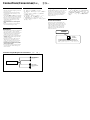
Mounting example
Installing in the dashboard
Ejemplo de montaje
Instalación en el salpicadero
ƒw‚¸¤ ⁄l
ƒw‚¸' » “ “O⁄Wfi
Bend these claws, if necessary.
Si es necesario, doble estas pestañas.
ƒpƒ‡¥†›n¡A§Ø¯s‡o¤˙⁄p`l⁄ø¡C
5
3
1
2
1
Dashboard
Salpicadero
»““O
Fire wall
Panel cortafuegos
¤⁄ı
4
5
6
4
Remove the bracket.
Retire el soporte.
§Ø⁄U⁄ ‹[
To support the unit
Sujeción de la unidad
›n'T'w¥» fi
1
Mounting the unit in a Japanese car
You may not be able to install this unit in some makes of Japanese
cars. In such a case, consult your Sony dealer.
Montaje de la unidad en un automóvil
japonés
Usted no podrá instalar esta unidad en algunos automóviles
japoneses. En tal caso, consulte a su proveedor Sony.
›nƒw‚¸' ⁄Ø¥»¤T¤fi‚ fi
ƒ‡“”⁄Ø¥»†£¤T¤fi⁄£fl ƒw‚¸¥» ¡Aƒ„fi ¡A‰—ƒV–z“” SONY ‚g P'–‹d
‚¡C
65
5
6
2
3
NISSANTOYOTA
to dashboard/center console
al salpicadero/consola central
ƒ » “ “O¡ ⁄⁄¥¡––¤ ‰c
to dashboard/center console
al salpicadero/consola central
ƒ » “ “O¡ ⁄⁄¥¡––¤ ‰c
Bracket
Soporte
⁄‹[
6
max. size
ø 5 × 8 mm
Tamaño máx.
ø 5 × 8 mm
‡ ⁄j⁄ ⁄o
ø 5 × 8 mm
Bracket
Soporte
⁄‹[
6
max. size
ø 5 × 8 mm
Tamaño máx.
ø 5 × 8 mm
‡ ⁄j⁄ ⁄o ø 5 × 8 mm
6
max. size
ø 5 × 8 mm
Tamaño máx.
ø 5 × 8 mm
‡ ⁄j⁄ ⁄o
ø 5 × 8 mm
6
max. size
ø 5 × 8 mm
Tamaño máx.
ø 5 × 8 mm
‡ ⁄j⁄ ⁄o ø 5 × 8 mm
1
Note
To prevent malfunction, install only with the supplied screws 6.
Nota
Para evitar que se produzcan fallos, realice la instalación solamente con
los tornillos suministrados 6.
ø
‹ ¤ ⁄ o¥˝•N¥~¤˘‹G¡Aƒw‚¸fi ¥ufl ¤ˇ¥˛“ ˜ “”`‡ •
6
¡C

Caution
•This unit is designed for negative ground 12 V
DC operation only.
•Before making connections, disconnect the
ground terminal of the car battery to avoid
short circuits.
•Connect the yellow and red power input leads
only after all other leads have been connected.
•Be sure to connect the red power input lead to
the positive 12 V power terminal which is
energized when the ignition key is in the
accessory position.
•Run all earth wires to a common ground
point.
•Be sure to insulate any loose unconnected
wires with electrical tape for safety.
“‘•N
• ¥» ¥u¥i¤ˇ¥˛›t•¥– ƒa12 V “‰‹y„q §@¡C
• ‡s–¥H«e¡A¥ ' ¥h¤T¤fi„qƒ “”– ƒa”⁄l¡A¥H§Ko
¥˝ u‚¡C
• ‹ıƒ ⁄˛¶ ƒ „q•‰¿Ø⁄J ‰u¥†¶• ¥' ƒ‡„q‰u‡£‡s–
§„†ƒ¥H«Æ⁄~¥i‡s–¡C
• ‹ıƒ „q•‰¿Ø⁄J ‰u‰—‡s–¤¤T¤fi o ˚´I⁄ı˘_ ˝
‡Q´ƒb»†§Uƒ‚mfi⁄~‡q„q“”¥¿12 V „q•‰” ⁄l¡C
• ' ƒ‡ƒa‰u‡£¥†» ‡s–¤ƒP⁄@–ƒa´I⁄~ƒ¡C
• ‹⁄Fƒw¥¡A‰—‰T»{§¤Sƒ‡‡s–“” ‰u¥˛„q „‰ƒ–a
¥]†ˇ¶iƒ·‰t¡C
Frequency select switch
The AM (FM) tuning interval is factory-set to the
9K (50K) position. If the frequency allocation
system of your country is based on 10 kHz (200
kHz) interval, set the switch on the bottom of
the unit to the 10K (200K) position before
making connections.
Connections/Conexiones/‰u‚ ⁄§‡s–
W†v¿¶}ˆ
¥»‚¸‚m“” AM (FM) ‰ ¿ ¶¡„jƒb¥X…t¥H«e‡Q‡]
'wƒb ¡§9 K (50 K)¡¤ƒ ‚m⁄W¡C›Y¶Qƒa“” W†v⁄ t¤t
†˛‹O¥H¡§10 kHz (200 kHz)¶¡„j‹ ´ƒ“”¡A‡s–¥H«e
‰—¥§¥» '‡“”¿ ¶}ˆ‡]'wƒb¡§10 K (200 K)¡¤
⁄§‡B¡C
Precauciones
•Esta unidad ha sido diseñada para alimentarse
con 12 V CC, negativo a masa, solamente.
•Antes de realizar las conexiones, desconecte el
terminal de puesta a masa de la batería del
automóvil a fin de evitar cortocircuitos.
•Conecte los cables conectores de alimentación
amarillo y rojo solamente después de haber
conectado los demás.
•Cerciórese de conectar el cable conector de
alimentación rojo a un terminal de 12 V
positivo que se energice al poner la llave de
encendido en la posición para accesorios.
•Conecte todos los conductores de puesta a
masa a un punto común.
•Por razones de seguridad, asegúrese de aislar
con cinta eléctrica los cables sueltos que no
estén conectados.
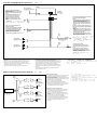
Connection diagram/Diagrama de conexiones/‰u‚‡s– ⁄Ł¶ „ˇ
Front speakers
Altavoces delanteros
«e·›`n „
Rear speakers
Altavoces traseros
«Æ·›`n „
XR-1100
Selector de frecuencia
El intervalo de sintonía de AM (FM) ha sido
ajustado en fábrica a la posición 9K (50K). Si el
sistema de asignación de frecuencias de su país
se basa en el intervalo de 10 kHz (200 kHz),
ponga este selector, situado en la base de la
unidad, en la posición 10K (200K) antes de
realizar las conexiones.
Change the position with a jeweler’s screwdriver, etc.
Cambie la posición con un destornillador de relojero, etc.
¥Hfl]˜_ƒ ¥˛“”¥ ” ƒy†“”`‡•_⁄l ¥§¯¶}ˆƒ‚m¡C
9 k (50 k)
10 K (200 K)

Connection example/Ejemplo de conexiones/‰u‚ ⁄§‡s– „ˇ¤
Red
Rojo
‹ıƒ
Yellow
Amarillo
¶ƒ
Front speakers
Altavoces delanteros
«e·›`n „
Rear speakers
Altavoces traseros
«Æ·›`n „
Fuse (10 A)
Fusible (10 A)
«OI•¡]10 A¡^
7
from a car antenna
de la antena del automóvil
¤ƒ¤T¤fi⁄ ‰u
Blue
Azul
´¯ƒ
Black
Negro
¶´ƒ
ANT REM
Max, supply current 0.1 A
Corriente máx. de 0,1 A
‡⁄j¤„q¶q 0.1 A
to the +12 V power terminal which is
energized at all times
Be sure to connect the black earth lead first.
a un terminal de alimentación de +12V
que esté permanentemente energizado
Asegúrese de conectar primero el
conductor de puesta a masa negro.
ƒ Hfi‡£‡B' ‡q„q“‹”A“”+12V„q•‰” ⁄l
¶iƒ ƒ„¶ ¤B˘Jfi¡A¶•¥ ‡s–⁄@¶´ƒ ƒa‰u¡C
to the +12 V power terminal which is
energized in the accessory position of the
ignition key switch
Be sure to connect the black earth lead to
it first.
a un terminal de alimentación de +12 V
que se energice en la posición para
accesorios de la llave de encendido
Asegúrese de conectar primero a este
terminal el conductor de puesta a masa
negro.
–ƒ¥uƒb´I⁄ı¶}ˆ C ˝´ ƒ »†§Uƒ‚mfi ⁄Ł⁄~‡q„q
“”+12V„q•‰” ⁄l
¶iƒ ƒ„¶ ¤B˘Jfi¡A¶•¥ ‡s–⁄@¶´ƒ ƒa‰u¡C
XR-1100
to a metal point of the car
First connect the black earth lead, then
connect the yellow and red power input
leads.
a un elemento metálico del automóvil
Conecte primero el conductor de puesta a
masa negro, y después, los cables de entrada
de alimentación amarillo y rojo.
ƒ¤T¤fi“ ˜ ‡¡⁄
›”¥ ‰—‡s– ¶´ƒ ƒa‰u¡AM«Æ⁄~‡s– ¶ ƒ ⁄˛‹ıƒ “”„q
•‰‰ ⁄J ‰u¡C
to the power aerial control lead or power supply
lead of an aerial booster amplifier
<Notes>
• It is not necessary to connect this lead if there
is no power aerial or aerial booster,or with a
manually-operated telescopic aerial.
• When your car has a built-in FM/AM aerial in
the rear/side glass, see "Notes on the control
leads."
al cable de control de la antena motorizada o al
cable de fuente de alimentación del amplificador
de antena
<Notas>
• Si no se dispone de antena motorizada ni de
amplificador de antena, o se utiliza una antena
telescópica accionada manualmente, no será
necesario conectar este cable.
• Si el automóvil incorpora una antena de FM/
AM en el cristal trasero/lateral, consulte "Notas
sobre conductores de control ".
ƒ„q ˚⁄ ‰u––¤ ‰u'˛⁄ ‰u⁄ £'æ⁄j „“”„q•‰ ‰u
¡ø¡
• ƒpL„q ˚⁄ ‰u'˛ L⁄‰u…W£„¡A'˛–aƒ‡⁄˚§@“”
' §⁄ ‰ufi¡A«K⁄£¥†‡s–ƒ„ ‰u¡C
• •–z“”¤T¤fiƒb«Æ/ …‹`…¡⁄Wƒ‡⁄”‚mFM/AM ⁄‰ufi¡A
§Y‰— ‹ ¡“––¤‰u¶•“ ¡“¡C
Notes on the control leads
• The power aerial control lead (blue) supplies 12V DC when you turn on
the unit.
• When your car has a built-in FM/AM aerial in the rear/side glass, it is
necessary to connect the power aerial control lead (blue) or the
accessory power input lead (red) to the power terminal of the existing
aerial booster. For details, consult your dealer.
• A power aerial without relay box cannot be used with this unit.
Notas sobre conductores de control
• El conductor de control de la antena motorizada (azul) suministrará +
12 V CC cuando conecte la alimentación de la unidad.
• Si el automóvil dispone de una antena de FM/AM incorporada en el
cristal trasero/lateral, será necesario conectar el cable de control de
antena motorizada (azul) o el cable auxiliar de entrada de
alimentación (rojo) al terminal de alimentación del amplificador de
antena existente. Para obtener información detallada, consulte a su
proveedor.
• Con esta unidad no podrá emplearse una antena motorizada
desprovista de caja de relé.
––¤ ‰u¶•“
•
•–z¥·¶} „fi ¡A„q ˚⁄ ‰u“”––¤ ‰u¡}´¯ƒ ¡~§Y¥io¥˝12VDC„q‹y¡C
•
•–z“”¤T¤fiƒb«Æ/ …‹`…¡⁄Wƒ‡⁄”‚mFM/AM⁄‰ufi¡A§Y‰—§ „q ˚⁄ ‰u––¤ ‰u
¡}´¯ƒ ¡~'˛“˜„q•‰¿Ø⁄J ‰u¡}‹ıƒ ¡~‡s–¤†{ƒ‡“”⁄ ‰u…W£„“”„q•
‰
⁄W¡C‚ † ⁄”fie¡A‰—‹¢‚‚gP ¡C
•
⁄£–a˜~„q „‰c“”„q ˚⁄ ‰u‹O⁄£fl¥˛' ¥» “”¡C
Speaker connections/Conexión de los altavoces/·›`n „⁄§‡s–
‡s–·›`n „fi “”“‘•N¤˘¶
•
·›`n „‰—¤ˇ¥˛“ § ‹4¤ 8… 'i⁄§¶¡¡A¤ˆ¤ªƒ‡ AƒX¥» ¤ˇ¥˛“”¥\†v
fie¶q“¡C§_«h•|•lˆa·›`n „¡C
•
⁄£¥i§·›`n „” ⁄l‡s–¤¤T¤fi'‡‰L¡A⁄]⁄£¥i§ ¥“·›`n „'M¥k
`n „‹ ‡s–¡C
•
·›`n „⁄£¥i¥›ƒ “”‡s–¡C
•
⁄£¥i‡s– ƒ‡•‰·›`n „(⁄”‚¸ƒ‡'æ⁄j „“)ƒ ¥» “”·›`n „” ⁄l¡A§_
«h•|•lˆaƒ‡•‰·›`n „¡C‡o¤˙” ⁄l¥ufl‡s– L•‰·›`n „¡C
Notes on speaker connection
• Use speakers with an impedance of 4 to 8 ohms, and with
adequate power handling capacities. Otherwise, the
speakers may be damaged.
• Do not connect the terminals of the speaker system to the
car chassis, and do not connect the terminals of the right
speaker with those of the left speaker.
• Do not connect the speakers in parallel.
• Do not connect any active speakers (with built-in
amplifiers) to the speaker terminals of the unit. Doing so
may damage the active speakers. Therefore, be sure to
connect passive speakers to these terminals.
Notas sobre la conexión de los altavoces
• Emplee altavoces con una impedancia de 4 a 8 ohmios, y
con la capacidad máxima de potencia adecuada. De lo
contrario, los altavoces podrían dañarse.
• No conecte los terminales del sistema de altavoces al
chasis del automóvil, ni los del altavoz derecho a los del
izquierdo.
• No intente conectar los altavoces en paralelo.
• No conecte altavoces activos (con amplificadores
incorporados) a los terminales de altavoces de la unidad.
Si lo hiciese, podría dañar tales altavoces. Por lo tanto,
cerciórese de conectar altavoces pasivos a estos
terminales.
White
Blanco
¥ƒ
Gray
Gris
ƒ˙ƒ
Green
Verde
”æƒ
Purple
Púrpura
ƒ
Left
Izquierdo
¥“
Right
Derecho
¥k
Left
Izquierdo
¥“
Right
Derecho
¥k
E : Striped cord
E : Cable con raya
E : –łfl „q‰u
Front speakers
Altavoces delanteros
«e·›`n „
Rear speakers
Altavoces traseros
«Æ·›`n „
XR-1100
-
 1
1
-
 2
2
-
 3
3
-
 4
4


