
©2016-2017 Universal Forest Products, Inc. All rights reserved.
68956 U.S. Hwy 131, White Pigeon, MI 49099 616.365.4201 9209_2/17
www.ufpi.com
A general rule of thumb is to place 1/3 of the post into the ground.
Check local regulations for any special requirements. The fence
will be stronger if the end, corner and gate posts are set at least
6" deeper than the line posts. Using a posthole digger or power
auger, dig the holes 10-12" wide and 6" deeper than needed.
Backfill the holes with 6" of gravel to drain water away from the
bottom of the posts (fig. 1). Keep the height of your fence panels
in mind when digging your postholes.
Starting in the corner, mix concrete in the first hole per the
instructions on the bag. Mix thoroughly and install the post into
the hole and tap the post to
the proper depth. We rec-
ommend a 2" gap from the
ground to the bottom of the
panel. Use a level to ensure
the fence post is plumb
and the post is square with
the ground. Brace the post
with temporary supports as
the concrete sets (per the
instructions).
Check local ordinances and regulations before building your
fence. Before construction, contact your local utility companies
to mark any underground cables and pipelines. In addition, it is
a good idea to discuss plans with any neighbors along your
proposed fence line.
Step 3Preparation
Digging postholes
• Determine the number of posts, panels and gates needed to
complete the job based on the total linear footage. Take into
consideration post, panel and gate widths when determining
the total number of each.
• Adjust layout to accommodate as many full panels as possible.
If you must use a partial panel, place it in the farthest rear
corner of the property.
• Locate property boundaries and drive stakes into the ground
at corners and ends of fence line, based on local municipality
regulations.
• Stretch twine or heavy string between stakes and pull tight
to mark layout of fence line.
• Be sure to measure your fence panels and gates prior to
determining the location of the postholes. Place posts in the
following order along string line:
• End/corner posts • Gate posts • Line posts
Design and layout
36" to 42"
10" to 12"
Diameter
Level
Fig.4.pdf
fig. 1
Items you may need
• Fence posts*
• Posthole digger
• Measuring tape
• Clear PVC cement
• Drill
• Screwdriver
• Level
• Chop saw
• String line
• Concrete
• Gravel
• Shims
• Pencil
• Safety glasses
• Gloves
* One per panel, plus one to complete the fence run.
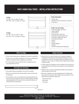
WOODBRIDGE OPEN PICKET TOP
PANEL ASSEMBLY INSTRUCTIONS
Kit contents
• 15 — Panel pickets
• 2 — U-channels
• 1 — 3.5" Top rail
• 1 — 5.5" Mid rail
• 1 — 5.5" Reinforced
bottom rail
• 23 — Pickets
WoodbridgePickFig1.ai
WoodbridgePickFig1.ai
Picket Top Panel Dimensions – 94.5" W x 68.75" H
(54" H solid panel)
Scallop Picket Top Panel Dimensions – 94.5" W x 68.45" H
(54" H solid panel)

©2016-2017 Universal Forest Products, Inc. All rights reserved.
68956 U.S. Hwy 131, White Pigeon, MI 49099 616.365.4201 9209_2/17
www.ufpi.com
Assembling the panel
STEP 1
Install first post with concrete (See “Digging postholes” and fig. 1).
STEP 2
Slide the bottom rail into place at the bottom of the routed
post (fig. 2).
STEP 3
Install the second post into the ground and temporarily secure
into place. Set the bottom rail into the second post and level (fig. 3).
(You will secure the second post with concrete in Step 9.)
STEP 4
Slide one U-channel onto the first picket and center it vertically.
Place the bottom of the first picket (with U-channel attached)
securely into the channel of the bottom rail and slide against
the first post. The U-channel should be between the post and
the picket (fig 4).
STEP 5
Continue installing each picket. The pickets feature a tongue-and-
groove design so that each picket fits securely into the one next
to it. Repeat with each picket until there is one picket left (fig. 5).
STEP 6
Slide the second U-channel on to the last picket and center it
vertically. Install the last picket (fig. 6).
STEP 7
When all pickets have been placed, insert the mid rail into the
middle routed hole in the first post. The mid rail has a channel on
one side and routed holes on the other. Insert the rail channel-side
down. Working from one side to the other, slide the rail over the
pickets. In order to insert the rail into the routed hole in the second
post, shift the post slightly until the rail can be fitted (fig. 7).
STEP 8
Insert the pickets into the routed holes in the mid rail (fig. 8).
STEP 9
Insert the top rail into the routed hole in the first post and carefully
place the top rail over the pickets, making sure each picket slides
through each routed hole in the top rail (fig. 9). In order to insert the
rail into the routed hole in the second post, shift the post slightly until
the rail can be fitted. Once the rail is securely locked in, the pickets
will form a solid panel.
Backfill the second post with concrete and make sure it’s set
before moving down the fence line. This will always allow one post
to be anchored while each panel section is assembled. To continue
building your fence line, repeat Steps 1-9.
WoodbridgePickFig2.ai
WoodbridgePickStep3.ai
fig. 2
fig. 3
WOODBRIDGE OPEN PICKET TOP PANEL ASSEMBLY INSTRUCTIONS, CONTINUED
WoodbridgePickStep4.ai
WoodbridgePickStep6.ai
WoodbridgePickFig5.ai
WoodbridgePickFig8.ai
WoodbridgePickFig7.ai
fig. 4
fig. 6
fig. 5
fig. 7
fig. 9fig. 8
WoodbridgePickFig6.ai
THE DIAGRAMS AND INSTRUCTIONS IN THIS BROCHURE ARE FOR ILLUSTRATION PURPOSES
ONLY AND ARE NOT MEANT TO REPLACE A LICENSED PROFESSIONAL. ANY CONSTRUCTION OR
USE OF THE PRODUCT MUST BE IN ACCORDANCE WITH ALL LOCAL ZONING AND/OR BUILD-
ING CODES. THE CONSUMER ASSUMES ALL RISKS AND LIABILITY ASSOCIATED WITH THE
CONSTRUCTION OR USE OF THIS PRODUCT. THE CONSUMER OR CONTRACTOR SHOULD TAKE
ALL NECESSARY STEPS TO ENSURE THE SAFETY OF EVERYONE INVOLVED IN THE PROJECT,
INCLUDING, BUT NOT LIMITED TO, WEARING THE APPROPRIATE SAFETY EQUIPMENT.
EXCEPT AS CONTAINED IN THE WRITTEN LIMITED WARRANTY, THE WARRANTOR DOES NOT
PROVIDE ANY OTHER WARRANTY, EITHER EXPRESS OR IMPLIED, AND SHALL NOT BE LIABLE
FOR ANY DAMAGES, INCLUDING CONSEQUENTIAL DAMAGES.

©2016-2017 Universal Forest Products, Inc. Todos los derechos reservados.
68956 U.S. Hwy 131, White Pigeon, MI 49099 616.365.4201 9209_2/17
www.ufpi.com
CERCA DE ESTACAS CON ESPACIAMIENTO
EN LA PARTE SUPERIOR WOODBRIDGE
INSTRUCCIONES DE ARMADO DEL PANEL
Contenido del kit
Panel de 6x8
• 15 — Tablones de panel
• 2 — Canales en U
• 1 — Riel superior de 8.9 cm (3.5 pulg.)
• 1 — Riel intermedio de 14 cm (5.5 pulg.)
• 1 — Riel inferior reforzado de 14 cm (5.5 pulg.)
• 23 — Tablones
Una regla general es enterrar 1/3 del poste. Verifique si las regula-
ciones locales marcan algún requerimiento especial. La cerca será
más sólida si los postes terminales, de esquinas y de puertas se
colocan al menos 15.2 cm (6 pulg.) más profundos que los postes de
línea. Utilizando una excavadora de postes o un barreno motorizado
excave los agujeros de 25.4 a 30.5 cm (10 a 12 pulg.) de diámetro y
15.2 cm (6 pulg.) más profundos de lo necesario. Rellene los agujeros
con 15.2 cm (6 pulg.) de grava para drenar agua de la base de los
postes (fig. 1). Tenga en mente la altura de sus paneles de cerca al
excavar sus agujeros para postes.
poste con soportes temporales mientras el concreto seca (de acuerdo
con las instrucciones).
Comenzando en la esquina,
mezcle concreto en el primer
agujero siguiendo las instruc-
ciones de la bolsa. Mezcle com-
pletamente e instale el poste
dentro del agujero, entierre
el poste hasta la profundidad
apropiada: Recomendamos
dejar un espacio de 5.1 cm (2
pulg.) desde el suelo hasta la
parte inferior del panel. Use un
nivel para asegurarse de que el
poste de la cerca está recto y
perpendicular al piso. Sujete el
Revise las ordenanzas y regulaciones locales antes de instalar su
cerca. Antes de iniciar la construcción, contacte a las compañías de
servicios públicos locales para identificar la presencia de cualquier
cable o tubería subterránea. Además, es una buena idea hablar sobre
sus planes con cualquier vecino que vaya a estar en la línea en la que
piensa instalar su cerca.
Step 3Preparación
Excavación de agujeros para postes
• Determine la cantidad de postes, paneles y puertas necesarios para
completar el trabajo con base en la distancia lineal total. Considere
la anchura de los postes, paneles y puertas al determinar la cantidad
total de cada uno.
• Ajuste la disposición para utilizar la mayor cantidad posible de
paneles completos. Si debe usar un panel parcial, colóquelo en
el rincón más oculto de la propiedad.
• Ubique los límites de la propiedad y coloque estacas en el suelo en
las esquinas y extremos de la cerca, con base en las regulaciones
municipales locales.
• Tienda una cuerda o cordón grueso entre las estacas y estírelo
para marcar la disposición de la cerca.
• Asegúrese de medir sus paneles de cerca y puertas antes de
determinar la ubicación de los agujeros para los postes. Coloque
los postes en el siguiente orden a lo largo de la línea marcada por
el cordón.
• Postes terminales o de esquinas • Postes de puerta
• Postes de línea
Diseño y disposición
36" to 42"
10" to 12"
Diameter
Level
Fig.4.pdf
fig. 1
Artículos que puede necesitar:
• Postes para cerca*
• Excavadora para
postes
• Cinta de medir
• Cemento claro
para PVC
• Taladro
• Destornillador
• Nivel
• Sierra ingletadora
• Cordel para marcar
• Concreto
• Grava
• Cuñas
• Lápiz
• Lentes de
seguridad
• Guantes
*Uno por panel, más
uno para terminar el
tramo de cerca.
WoodbridgePickFig1.ai
WoodbridgePickFig1.ai
Dimensiones del panel superior – 240 cm (94.5 pulg.) de ancho x
174.6 cm (68.75 pulg.) de alto
(panel sólido de 137.2 cm (54 pulg.) de alto)
Dimensiones del panel superior de la cerca festoneada –
240 cm (94.5 pulg.) de ancho x 173.9 cm (68.45 pulg.) de alto
(panel sólido de 137.2 cm (54 pulg.) de alto)
Nivel
25.4 a 30.5 cm
(10 a 12 pulg.)
de diámetro
91.4 a 106.7 cm
(36 a 42 pulg.)

©2016-2017 Universal Forest Products, Inc. Todos los derechos reservados.
68956 U.S. Hwy 131, White Pigeon, MI 49099 616.365.4201 9209_2/17
www.ufpi.com
Armado del panel
PASO 1
Instale el primer poste con concreto (“Excavación de agujeros para
postes” y fig. 1).
PASO 2
Deslice el riel inferior en su sitio en la parte inferior del poste
ranurado (fig. 2).
PASO 3
Instale el segundo poste en el piso y sujételo temporalmente en su
sitio. Sujete el riel inferior al segundo poste y nivélelo (fig. 3). (Sujetará
el segundo poste con concreto en el Paso 9).
PASO 4
Deslice el canal en U sobre el primer tablón y céntrelo verticalmente.
Coloque la parte inferior del primer tablón (con el canal en U coloca-
do) dentro del canal del riel inferior y deslícelo contra el primer poste.
El canal en U debe estar entre el poste y el tablón (fig. 4).
PASO 5
Siga instalando cada tablón. Los tablones tienen un diseño de lengüeta
y ranura, de modo que cada uno encaja en que está al lado. Repita
con cada tablón hasta que quede un solo tablón (fig. 5).
PASO 6
Deslice el segundo canal en U sobre el último tablón y céntrelo vertical-
mente. Instale el último tablón (fig. 6).
PASO 7
Después de colocar todos los tablones, inserte el riel intermedio en
el agujero intermedio del primer poste. El riel intermedio tiene un
canal en uno de sus lados y agujeros taladrados en el otro. Inserte
el riel con el canal hacia abajo. Trabajando de lado a lado, deslice el
riel sobre los tablones. Para insertar el riel en el agujero del segundo
poste, mueva el poste ligeramente hasta que pueda ajustar el riel
(fig. 7).
PASO 8
Inserte los tablones en los agujeros del riel intermedio (fig. 8).
PASO 9
Inserte el riel superior en el agujero del primer poste y coloque
cuidadosamente el riel superior sobre los tablones, asegurándose de
que cada tablón se deslice a través de cada agujero del riel superior
(fig. 9). Para insertar el riel en el agujero del segundo poste, mueva el
poste ligeramente hasta que pueda ajustar el riel. Una vez que el riel
quede bien sujeto, los tablones formarán un panel sólido.
Rellene el agujero del segundo poste con concreto y asegúrese de
que está seco antes de continuar con la cerca. De este modo siempre
habrá un poste anclado mientras arma una sección de panel. Para
seguir construyendo su cerca, repita los pasos 1 a 9.
CERCA DE ESTACAS CON ESPACIAMIENTO EN LA PARTE SUPERIOR WOODBRIDGE
INSTRUCCIONES DE ARMADO DEL PANEL, CONTINUACIÓN
LOS DIAGRAMAS Y LAS INSTRUCCIONES QUE SE MUESTRAN SON SÓLO PARA FINES
ILUSTRATIVOS Y NO SUSTITUYEN A UN PROFESIONAL CON LICENCIA. CUALQUIER
CONSTRUCCIÓN O USO DEL PRODUCTO DEBE ESTAR EN CONFORMIDAD CON TODOS LOS
CÓDIGOS LOCALES DE ZONIFICACIÓN Y/O DE CONSTRUCCIÓN. EL CONSUMIDOR ASUME
TODOS LOS RIESGOS Y RESPONSABILIDADES ASOCIADOS CON LA CONSTRUCCIÓN O EL
USO DE ESTE PRODUCTO. EL CONSUMIDOR O CONTRATISTA DEBE TOMAR TODAS LAS
MEDIDAS NECESARIAS PARA GARANTIZAR LA SEGURIDAD DE TODOS LOS INVOLUCRADOS
EN EL PROYECTO, INCLUYENDO, PERO NO LIMITADO AL, USO DEL EQUIPO DE SEGURIDAD
APROPIADO. EXCEPTO POR LO QUE SE INDICA EN LA GARANTÍA LIMITADA POR ESCRITO,
EL GARANTE NO OFRECE NINGUNA OTRA GARANTÍA, EXPRESA O IMPLÍCITA, Y NO SERÁ
RESPONSABLE POR NINGÚN DAÑO, INCLUSO DAÑOS CONSECUENTES.
WoodbridgePickFig2.ai
WoodbridgePickStep3.ai
fig. 2
fig. 3
WoodbridgePickStep4.ai
WoodbridgePickStep6.ai
WoodbridgePickFig5.ai
WoodbridgePickFig8.ai
WoodbridgePickFig7.ai
fig. 4
fig. 6
fig. 5
fig. 7
fig. 9fig. 8
WoodbridgePickFig6.ai
-
 1
1
-
 2
2
-
 3
3
-
 4
4
Veranda 144731 Instrucciones de operación
- Tipo
- Instrucciones de operación
- Este manual también es adecuado para
en otros idiomas
Artículos relacionados
-
 Veranda 246062 Guía de instalación
-
 Veranda 128017 Guía de instalación
-
 Veranda 141568 Guía de instalación
-
 Veranda 141569 Instrucciones de operación
-
 Veranda 361670 Instrucciones de operación
-
 Veranda 144727 Instrucciones de operación
-
 Veranda 144729 Instrucciones de operación
-
 Veranda 128016 Guía de instalación
-
Outdoor Essentials 53990 Guía de instalación
-
 Veranda 53990 Guía de instalación


