Zanussi ZHP622NX Manual de usuario
- Categoría
- Campanas de cocina
- Tipo
- Manual de usuario

MANUALE DI INSTALLAZIONE, USO E MANUTENZIONE
INSTALLATION, USE AND MAINTENANCE HANDBOOK
MANUEL D’INSTRUCTIONS POUR L’INSTALLATION, L’EMPLOI ET L’ENTRETIEN
HANDBUCH FÜR INSTALLATION, BEDIENUNG UND WARTUNG
INSTRUCTIES VOOR MONTAGE, GEBRUIK EN ONDERHOUD
MANUAL DE INSTRUCCIONES, USO Y MANTENIMIENTO
MANUAL DE INSTRUÇÕES, UTILIZAÇÃO E MANUTENÇÃO

2
Contenuti - Contenents - Sommaire - Inhalt - Inhoud - Indice - Indice
Istruzioni per L’Installazione - Installation Instructions
Instructions pour L’Installation - Montagehinweise
Instructies voor de Installatie - Instrucciones de Instalacion
Instruções para a Instalação
Generalità .................................................................................................................... 5
General Information ................................................................................................... 9
Generalites ................................................................................................................... 13
Allgemeines ................................................................................................................. 17
Algemeen ..................................................................................................................... 21
Generalidades .............................................................................................................. 25
Informações de segurança ........................................................................................... 29
Avvertenze per la Sicurezza ......................................................................................... 5
Safety Warnings .......................................................................................................... 9
Conseils concernant la Securite .................................................................................. 13
Sicherheitshinweise ...................................................................................................... 17
Veiligheidsmaatregelen ................................................................................................ 21
Normas de seguridad .................................................................................................. 25
Precauções de segurança ............................................................................................. 29
Installazione ................................................................................................................. 5
Installation .................................................................................................................. 9
Installation .................................................................................................................. 13
Montage des Gerätes ................................................................................................... 18
Installatie ..................................................................................................................... 21
Instalacion ................................................................................................................... 25
Instalação ..................................................................................................................... 29
Installazione nel pensile ......................................................................................... 5
Installation in the overhead unit ........................................................................... 9
Installation dans l’élément haut ............................................................................. 13
Montage des Hängeschranks .................................................................................. 18
Installatie in het kastje .......................................................................................... 21
Colocación en el armario ...................................................................................... 25
Instalação no móvel suspenso ................................................................................. 29
Montaggio del distanziale ...................................................................................... 5
Fitting the spacer .................................................................................................. 9
Montage de l’entretoise .......................................................................................... 13
Montage des Abstandstückes ................................................................................... 18
Montage van het opvulstuk ................................................................................... 21
Para montar el distanciador ................................................................................. 25
Montagem do espaçador ........................................................................................ 29

3
Contenuti - Contenents - Sommaire - Inhalt - Inhoud - Indice - Indice
Connessione aspirante o filtrante ............................................................................ 6
Connecting up remote blower or filter system ......................................................... 10
Connexion aspirante ou filtrante ............................................................................ 14
Anschluß Abluft- oder Umluftbetrieb ...................................................................... 18
Afzuigende of filterende opstelling ........................................................................... 22
Conexión aspirante o filtrante ................................................................................ 26
Ligação filtrante ou aspirante ................................................................................ 30
Connessione elettrica e controllo funzionale ............................................................ 6
Connecting to the power supply and testing ........................................................... 10
Branchement électrique et contrôle fonctionnel ....................................................... 14
Elektrischer Anschluß und Funktionskontrolle ........................................................ 18
Elektrische aansluiting en controle van de werking ................................................. 22
Conexión eléctrica y control funcional .................................................................... 26
Ligação eléctrica e controle funcional ..................................................................... 30
Istruzioni per L’Uso e la Manutenzione - Operation and
Maintenance Instructions - Instructions pour L’Utilisation et
L’Entretien - Gebrauchs- und Wartungshinweise -
Gebruiksaanwijzing - Instrucciones de Uso y Mantenimiento -
Instruções para a Utilização e para a Manutenção
Avvertenze per la Sicurezza ......................................................................................... 7
Safety Warnings .......................................................................................................... 11
Conseils concernant la Securite .................................................................................. 15
Sicherheitshinweise ...................................................................................................... 19
Veiligheidsmaatregelen ................................................................................................ 23
Normas de Seguridad ................................................................................................. 27
Precauções de segurança ............................................................................................. 31
Uso .............................................................................................................................. 7
Use .............................................................................................................................. 11
Utilisation .................................................................................................................... 15
Bedienung ................................................................................................................... 19
Gebruik ....................................................................................................................... 23
Uso .............................................................................................................................. 27
Utilização ..................................................................................................................... 31
Manutenzione .............................................................................................................. 7
Maintenance ................................................................................................................ 11
Entretien ...................................................................................................................... 15

4
Wartung und Pflege ................................................................................................... 19
Onderhoud .................................................................................................................. 23
Mantenimiento ............................................................................................................ 27
Manutenção ................................................................................................................. 31
Filtri antigrasso metallici ...................................................................................... 7
Metal grease filters ................................................................................................ 11
Filtres à graisses métalliques .................................................................................. 15
Metall-Fettfilter .................................................................................................... 19
Metalen antivet-filter ............................................................................................ 23
Filtros antigrasa metálicos ..................................................................................... 27
Filtros metálicos antigordura ................................................................................. 31
Filtro antigrasso in fibra sintetica .......................................................................... 8
Synthetic fibre filter .............................................................................................. 12
Filtre synthétique .................................................................................................. 16
Fettfiltervlies ......................................................................................................... 19
Synhetisch vetfilter ................................................................................................ 23
Filtro antigrasa de fibra sintetica .......................................................................... 27
Filtro antigordura de fibra sintética ...................................................................... 32
Filtri al carbone attivo ......................................................................................... 8
Charcoal filters ..................................................................................................... 12
Filtres à charbon actif ........................................................................................... 16
Aktiv-Kohlefilter .................................................................................................... 20
Koolstoffilters ......................................................................................................... 24
Filtro de carbón activado ...................................................................................... 28
Filtros de carvão activo ......................................................................................... 32
Illuminazione ........................................................................................................ 8
Lighting ................................................................................................................ 12
Eclairage ............................................................................................................... 16
Beleuchtung ........................................................................................................... 20
Verlichting ............................................................................................................ 24
Iluminación .......................................................................................................... 28
Iluminação ........................................................................................................... 32
Pulizia ................................................................................................................. 8
Cleaning ............................................................................................................... 12
Nettoyage .............................................................................................................. 16
Pflege .................................................................................................................... 20
Reiniging .............................................................................................................. 24
Limpieza .............................................................................................................. 28
Limpeza ............................................................................................................... 32
Contenuti - Contenents - Sommaire - Inhalt - Inhoud - Indice - Indice

5
Parte1
a
- ISTRUZIONI PER L’INSTALLAZIONE
1 - GENERALITÀ.
Questa cappa è predisposta per essere installata nella parte inferiore di un pensile posto sopra un
piano di cottura, posizionato a ridosso di una parete. Può essere utilizzata in versione aspirante
(evacuazione esterna), oppure in versione filtrante (riciclo interno). Si raccomanda che l’installazio-
ne venga effettuata da personale specializzato, rispettando tutte le prescrizioni delle autorità
competenti relative allo scarico dell’aria da evacuare. Il produttore declina qualsiasi responsabilità
per danni dovuti ad installazione non corretta o non conforme alle regole dell’arte.
2 - AVVERTENZE PER LA SICUREZZA.
2.1 - Non collegare la cappa a condotti di scarico dei fumi prodotti da combustione (caldaie,
caminetti, ecc...).
2.2 - Verificare che la tensione di rete corrisponda a quella riportata nella targhetta posta
all’interno della cappa.
2.3 - Collegare la cappa alla rete interponendo un interuttore bipolare con apertura dei
contatti di almeno 3 mm.
2.4 - Accertarsi che l’impianto elettrico domestico garantisca un corretto scarico a terra.
2.5 - La distanza minima di sicurezza tra il piano di cottura e la cappa è di 65 cm.
2.6 - Non fare cucine alla fiamma sotto la cappa.
2.7 - Controllare le friggitrici durante l’uso: l’olio surriscaldato potrebbe infiammarsi.
2.8 - Prima di procedere a qualsiasi operazione di pulizia o di manutenzione, disinserire
l’apparecchio togliendo la spina o agendo sull’interruttore generale.
2.9 - Nel caso in cui nella stanza vengano utilizzati sia la cappa che apparecchi non azionati
da energia elettrica (ad esempio apparecchi utilizzatori a gas), si deve provvedere ad una
aerazione sufficiente dell’ambiente. Un uso proprio e senza rischi si ottiene quando la
depressione massima del locale non supera 0,04 mbar; si evita in questo modo un ritorno
dei gas di scarico.
3 - INSTALLAZIONE
Questo apparecchio appartiene alla categoria delle cappe semi-integrate. La parte superiore si
inserisce all'interno del pensile. Il carrello inferiore estraibile, a montaggio avvenuto, si trova
collocato all'esterno del pensile e deve essere estratto in posizione di lavoro.
3.1 - Installazione nel pensile
Utilizzando la dima di foratura in dotazione, realizzare nel fondo del pensile l'apertura necessaria
per introdurre la parte superiore della cappa. Aprire il carrello estraibile e togliere la griglia di
aspirazione, collocare la cappa nell'apertura e fissare la parte inferiore con le viti in dotazione del
sacchetto degli accessori.
3.2 - Montaggio del distanziale
Dopo aver fissato la cappa al pensile, può essere montato nella parte inferiore il distanziale in
dotazione, per chiudere lo spazio che rimane tra lo spigolo posteriore della cappa e la parete. Il
distanziale può essere regolato da un minimo di 1 mm ad un massimo di 30 mm.

6
Parte 1ª - ISTRUZIONI PER L’INSTALLAZIONE
3.3 - Connessione aspirante o filtrante.
1 - Connessione aspirante:
La cappa deve essere collegata a tubazioni esterne per mezzo di un tubo rigido o flessibile Ø
120 mm, da fissare con adeguate fascette stringitubo non in dotazione. Controllare l'eventuale
presenza dei filtri al carbone attivo all'interno del corpo cappa: nella versione aspirante non
devono essere montati (vedi paragrafo 3.3 parte 2a).
2 - Connessione filtrante:
La cappa deve essere collegata alla parte superiore del pensile per mezzo di un tubo rigido o
flessibile Ø 120 mm. Controllare che all'interno della cappa siano montati i filtri al carbone
attivo (vedi paragrafo 3.3 parte 2a). L'aria filtrata viene riciclata nell'ambiente attraverso
l'apertura posta nella parte superiore del pensile, può essere montata sopra il pensile nel caso
sia in dotazione, una griglia direzionata Ø 120 mm facendo attenzione ad orientare l'uscita
dell'aria nel verso opposto alla parete.
3.4 - Connessione elettrica e controllo funzionale
Il collegamento elettrico può essere effettuato come segue:
1 - Se la cappa é dotata di spina, può essere collegata direttamente ad una vicina presa di corrente
con scarico a terra.
2 - Con apposito impianto elettrico di collegamento dotato di scarico a terra, se l'apparecchio non
é corredato di spina. Rispettare assolutamente le avvertenze dei punti 2.3, 2.4 e 2.5 delle
avvertenze per la sicurezza.
3 - Effettuato il collegamento elettrico, verificare il corretto funzionamento di illuminazione,
accensione del motore, cambio delle velocità. Dopo aver installato la cappa, é necessario per
la prima volta, aprire il carrello scorrevole energicamente fino a sentire lo scatto di fine
corsa.

7
Parte 2ª - ISTRUZIONI PER L’USO E LA MANUTENZIONE
1 - AVVERTENZE PER LA SICUREZZA.
È assolutamente necessario rispettare tutte le avvertenze riportate al paragrafo 3 della 1
a
parte -
Istruzioni per l’installazione. In aggiunta, è molto importante fare particolare attenzione, nell’uso e
nella manutenzione, alle seguenti avvertenze:
1.1 - Effettuare una scrupolosa e tempestiva manutenzione dei filtri antigrasso e al carbone
attivo, secondo gli intervalli consigliati dal Fabbricante, o più frequentemente, per un uso
particolarmente gravoso (oltre le 4 ore giornaliere).
1.2 - Non lasciare fiamme libere a forte intensità sotto la cappa in funzione: togliendo le
pentole, spegnere la fiamma o almeno, per brevi periodi e sotto sorveglianza, tenerla al
minimo.
1.3 - Regolare sempre le fiamme in modo da evitare una evidente fuoriuscita laterale delle
stesse rispetto al fondo delle pentole: si risparmia energia e si evitano pericolose
concentrazioni di calore.
1.4 - Non fare mai un uso improprio dell’apparecchio, che è stato progettato esclusivamente
per abbattere gli odori in cucina.
2 - USO.
Un microinterruttore azionato dal movimento del carrello accende e spegne l'impianto di illumin
zione e attiva l'avvio e l'arresto del motore nelle condizioni precedentemente selezionate. Un
interruttore situato nella parte anteriore della cappa seleziona la velocità di esercizio:
1 = velocità minima (adatta ad ottenere un cambio di aria continuo, particolarmente silenzioso in
presenza di pochi vapori di cottura):
2 = velocità massima (adatta a fronteggiare le massime emissioni di vapori di cottura anche per
tempi prolungati).
3 - MANUTENZIONE
Una costante manutenzione garantisce un buon funzionamento ed un buon rendimento nel tempo.
Particolari attenzioni vanno rivolte ai filtri antigrasso e, per le sole cappe filtranti, ai filtri al carbone
attivo.
3.1 - Filtri antigrasso metallici.
1 - Pulizia:
È necessario lavare con normale detersivo domestico questi filtri al massimo ogni 2 mesi; la
loro dimensione compatta consente il lavaggio anche in lavastoviglie.
2 - Smontaggio dei filtri:
a) Aprire il carrello scorrevole.
b) Aprire la griglia di aspirazione premendo i pomelli di chiusura verso il centro e tirando
contemporaneamente verso il basso.
c) Togliere i fermafiltro in filo metallico e i filtri antigrasso.

8
Parte 2ª - ISTRUZIONI PER L’USO E LA MANUTENZIONE
3.2 - Filtro antigrasso in fibra sintetica.
1 - Non può essere lavato, ma va sostituito mediamente ogni due mesi. Se il filtro é dotato di
indicatori chimici di saturazione, sostituire quando il colore rosso dei puntini visibili dal-
l'esterno é diffuso su tutta la superficie.
2 - Sostituzione
a) Aprire il carrello scorrevole.
b) Aprire la griglia di aspirazione premendo i pomelli di chiusura verso il centro e tirando
contemporaneamente verso il basso.
c) Togliere i fermafiltro in filo metallico e sostituire il filtro antigrasso.
d) Richiudere la griglia di aspirazione.
3.3 - Filtro al carbone attivo.
1- Funzionamento:
I filtri al carbone attivo hanno la capacità di trattenere gli odori fino a raggiungere la satura-
zione. Non sono lavabili e non sono rigenerabili e vanno pertanto sostituiti almeno ogni 4
mesi o, più frequentemente, per un uso particolarmente intenso.
2 - Sostituzione:
a) Aprire il carrello scorrevole.
b) Aprire la griglia di aspirazione.
c) Sostituire i filtri al carbone attivo svitando i pomelli di fissaggio.
d) Richiudere la griglia di aspirazione.
ATTENZIONE: é necessario rispettare i tempi di manutenzione o sostituzione indicati, per
evitare un possibile rischio di incendio in caso di filtri saturi di grassi.
3.4 - Illuminazione.
a) É costituita da 1 o 2 lampade da 40W a cui si ha accesso togliendo la plafoniera trasparente.
b)Se le lampade non funzionano, controllare che siano ben avvitate.
c) Se le lampade sono bruciate, devono essere sostituite con altre di pari voltaggio e potenza.
3.5 - Pulizia
Per la normale pulizia della cappa:
- Non utilizzare panni o spugne bagnate, nè getti d’acqua;
- Non utilizzare diluenti o alcool poiché potrebbere opacizzare le superfici verniciate;
- Non utilizzare sostanze abrasive, in particolare sulle sperfici in acciaio inox.
Si consiglia di utilizzare un panno umido e detersivo liquido neutro.

9
1 - GENERAL INFORMATION
This canopy hood is designed to be fixed to any rigid vertical surface, over a gas or electric hotplate
and can be used either in the extraction mode (ducted to the outside) or in the recirculation mode
(internal recycling). Before commencing the installation, consideration should be given to the
difficulties to be found during installation and to the bulky weight of the hood. The installation
work must be undertaken by a qualified and competent person in conformity to the rules
concerning the evacuation of contaminated air. The manufacturer disclaims all liability for any
damage or injury caused as a result of not following the instructions for installation contained in
the following text.
2 - SAFETY WARNINGS
2.1 - When used in the extraction mode the cooker hood ducting must not be connected to a
flue which is used for exhausting fumes from appliances supplied with energy other than
electric, such as a central heating flue or water heating flue.
2.2 - Before connecting to the mains supply ensure that the mains voltage corresponds withthe
voltage on the rating plate inside the hood.
2.3 - Connect the cooker hood to the mains via a bipolar switch which has 3 mm clearance
between the contacts.
2.4 - The appliance must be earthed.
2.5 - When istalled, the hood must be positioned at least 65 cm above the hotplate.
2.6 - Never do flambé cooking under this cooker hood.
2.7 - Never leave frying pans unattended during use as overheated fats and oils may catch
fire.
2.8 - Before carring out any kind of maintenance or cleaning, disconnect the hood from the
mains supply.
2.9 - If the room where the cooker hood is to be used contains a fuel burning appliance such
as a central heating boiler then this must be of the room sealed or balanced flue type. If
other types of flue or appliance are fitted, ensure that there is an adequate supply of air
into the room. When the cooker hood is used in conjunction with other appliances
supplied with energy other than electric, the negative pressure in the room must not
exceed 0,04 mbar to prevent fumes being drawn back into the room by the cooker hood.
3 - INSTALLATION.
This unit belongs to the category of semi-fitted hoods. The top portion is inserted inside the
overhead unit. After assembly, the pull-out undercarriage is positioned outside the overhead unit
and must be pulled out into a working position.
3.1 - Installation in the overhead unit
Using the template provided, cut the opening required to insert the top portion of the hood in the
base of the overhead unit. Open the pull-out undercarriage and remove the blower grid, position
the hood in the opening and fix the bottom portion using the screws in the bag of fittings provided.
Part 1 - INSTALLATION INSTRUCTIONS

10
3.2 - Fitting the spacer
After having fixed the hood to the overhead unit, the spacer provided can be fitted to the bottom,
to close the space remaining between the rear edge of the hood and the wall. The spacer can be
adjusted from a minimum of 1 mm to a maximum of 30 mm.
3.3 - Connecting up remote blower or filter system
1 - Connecting up remote blower system
The hood must be connected to the external air outlet using Ø 120 mm rigid or flexible pipes,
fixed using suitable hose clamps (not provided). Check whether or not there are active carbon
filters inside the body of the hood; in the remote blower version they should not be fitted (see
paragraph 3.3 part 2).
2 - Connecting up filter system
The hood must be connected to the top portion of the overhead unit using a Ø 120 mm rigid
or flexible pipe. Check that the active carbon filters are fitted inside the body of the hood (see
paragraph 3.3. part 2). The filtered air is returned to the environment through the opening at
the top of the overhead unit. If provided, a Ø 120 mm directional vent can be installed on top
of the overhead unit, making sure that the air flow is not directed against the wall.
3.4 - Connecting to the power supply and testing
Connection to the power supply is as follows:
1 - If the hood is equipped with a plug, this can be connected directly to a near-by power socket,
provided the latter is adequately earthed.
2 - If the hood does not have a plug, it must be connected by means of a special power line,
which must be suitably earthed. The warnings given in points 2.3, 2.4 and 2.5 of the safety
precautions must always be observed.
3 - After connecting to the mains power supply, check that the lighting, motor start-up and speed
change all operate correctly.
After installing the hood, the pull-out undercarriage must be opened with a certain force,
until a click is heard indicating that it has reached its full extension.
Part 1 - INSTALLATION INSTRUCTIONS

11
1 - SAFETY WARNINGS
It is most important that all the warnings shown in paragr. 2 of part 1 are strictly observed.
Moreover, special attention must be paid to the following warnings during the use and maintenance
of the cooker hood:
1.1 - The grease filters should be cleaned as recommended by the manufacturer or more
frequently if the hood is used consistently (more than 4 hours per day).
1.2 - When using a gas hob in connection with the cooker hood never leave the burners of the
hob uncovered while the hood is in use or when the pans have been removed. Switch off
the gas before removing the pan or for just short periods and never leave the
hob unattended.
1.3 - Always ensure that the appliance is kept at the correct intensity to prevent the flame
from licking round from the bottom of the pan; this will save energy and will avoid a
dangerous concentration of heat.
1.4 - Always ensure that the appliance is used in accordance with the manufacturer's
instructions for the removal of contaminated odours during cooking.
2 - USE
A microswitch activated by movement of the undercarriage turns the lighting system on and off and
activates start-up and stoppage of the motor at the pre-selected speed. A switch at the front of the
hood is used to select the fan speed:
1 = minimum speed (particularly silent, ideal for a continuous exchange of air when steam and
vapour levels are low);
2 = maximum speed (to deal with high levels of steam and vapour even for extended periods).
3 - MAINTENANCE
Regular maintenance and cleaning will ensure good performance and reliability, while extending the
working life of the hood. Special attention should be paid to the grease filters and to the charcoal
filters when the hood is used in the recirculation mode.
3.1 - Metal grease filters.
1 - Cleaning:
The metal grease filter should be cleaned every two months with normal usage and can be
cleaned in a dishwasher or by hand using a mild detergent or liquid soap.
2 - Replacements:
a) Open the sliding visor.
b) Open the metal grille pushing the knobs towards the centre while pulling downwards.
c) Remove the wire clips and replace the synthetic fibre filter.
Part 2 - OPERATION AND MAINTENANCE INSTRUCTIONS

12
3.2 - Synthetic fibre filter.
1 - This type of filter is printed with red dots. When the filter becomes saturated the red colour of
the dots will spread over the whole surface of the filter. At this point the filter has to be
replaced. The saturated filter cannot be cleaned or regenerated.
2 - Replacement:
a) Open the sliding visor.
b) Open the metal grille pushing the knobs towards the centre while pulling downwards.
c) Remove the wire clips and replace the synthetic fibre filter.
d) Close the metal grille.
3.3 - Charcoal filters
1 - Functioning:
In the recycling mode the charcoal filters absorb smell and odours. The charcoal filter cannot
be washed or regenerated and should be replaced every 2 months or more frequently if the
hood is used consistently.
2 - Replacement:
a) Open the sliding visor.
b) Open the metal grille pushing the knobs towards the centre while pulling downwards.
c) Replace the charcoal filters by unscrewing the fixing knobs.
d) Close the metal grille.
ATTENTION - There could be a possible fire hazard if the filters are not replaced
according to these instructions.
3.4 - Lighting
a) One or two 40W lamps ensure the worktop lighting. These lamps can be reached by removing
the glass visor.
b) Should the two lamps fail to work, open the metal grille and ensure they are correctly screwed
into the holder.
c) When changing the lamp, an identical replacement must be fitted to ensure the safe working
of the cooker hood.
3.5- Cleaning
When cleaning the hood:
- Never use a wet cloth or sponge, or running water.
- Never use thinners or products containing alcohol, as they might damage the paintwork.
- Never use abrasive cleaning materials, in particular when cleaning stainless steel surfaces.
It is recommended to use a damp cloth and mild liquid household cleaner.
Part 2 - OPERATION AND MAINTENANCE INSTRUCTIONS

13
1 - GENERALITES
Cette hotte est prévue pour être installée dans la partie inférieure d'une armoire au dessus d'un plan
de cuisson, placée contre une paroi. Elle peut être utilisée en version évacuation (raccordement
extérieur) ou recyclage (recyclage interne). A cause de la complexité de l’appareil il est préférable
que l’installation soit effectuée par un spécialiste tout en respectant les prescriptions des autorités
concernant l'évacuation de l'air. La responsabilité du producteur ne saurait être engagée pour tout
incident ou accident provoqué par une installation défectueuse.
2 - CONSEILS CONCERNANT LA SECURITE
2.1 - N’utilisez jamais pour le raccordement une cheminée servant de conduit de fumée
(chaudières, cheminées, etc...).
2.2 - Vérifiez que la tension du secteur soit identique aux valeurs indiquées sur la plaquette
signalétique figurant à l’intérieur de la hotte.
2.3 - Reliez la hotte au réseau en interposant un interrupteur bipolaire avec ouverture des
contacts de 3 mm au moins.
2.4 - Assurez-vous que l’installation éléctrique de votre logement ait une mise à la terre
correcte.
2.5 - La distance de sûreté minimum entre le plan de cuisson et la hotte est de 65 cm.
2.6 - Il est interdit de faire flamber des préparations sous la hotte.
2.7 - Lorsque des fritures sont effectuées sous la hotte en fonctionnement, elles doivent faire
l’objet d’une surveillance permanente: l’huile surchauffée pourrait s’enflammer.
2.8 - Avant d’effectuer le nettoyage ou l’entretien de la hotte, débranchez l’appareil ou agissez
sur l’interrupteur omnipolaire de votre installation.
2.9 - Une ventilation convenable de la pièce doit être prévue si une hotte de cuisine et des
appareils alimentés par une énergie autre que l’énergie électrique évacuent les fumées
simultanément. Une utilisation sans dangers est possible si la dépression maximum qui se
crée dans la pièce est inférieure à 0,04 mbar, ce que évite un retour des gaz de décharge
dans la pièce.
3 - INSTALLATION
Cet appareil appartient à la catégorie des hottes semi-intégrées. La partie supérieure s'intègre à
l'intérieur de l'élément haut. Le chariot inférieur extractible, quand le montage a été effectué, se
trouve placé à l'extérieur de l'élément haut et doit être extrait en position de travail.
3.1 - Installation dans l'élément haut
En utilisant le gabarit de perçage, réaliser dans le fond de l'élément haut l'ouverture nécessaire pour
introduire la partie supérieure de la hotte. Ouvrir le chariot extractible et enlever la grille
d'aspiration, placer la hotte dans l'ouverture et fixer la partie inférieure avec les vis fournies qui se
trouvent dans le sachet des accessoires.
3.2 - Montage de l'entretoise
Après avoir fixé la hotte à l'élément haut, on peut monter dans la partie inférieure l'entretoise
fournie, pour clore l'espace restant entre l'arête postérieure de la hotte et la paroi. L'ntretoise peut
être réglée d'un minimum de 1 mm à un maximum de 30 mm.
1ère partie - INSTRUCTIONS POUR L’INSTALLATION

14
3.3 - Connexion aspirante ou filtrante
1 - Connexion aspirante
La hotte doit être raccordée à des tuyaux externes grâce à un tuyau rigide ou flexible Ø 120
mm, à fixer avec des colliers serre-tubes appropriés non fournis. Contrôler l'éventuelle
présence des filtres au charbon actif à l'intérieur du corps hotte; la version aspirante, ils ne
doivent pas être montés (voir paragraphe 3.3 partie 2
a
).
2 - Connexion filtrante
La hotte doit être raccordée à des tuyaux externes grâce à un tuyau rigide ou flexible Ø 120
mm. Contrôler qu'à l'intérieur de la hotte soient montés les filtres au charbon actif; (voir
paragraphe 3.3 partie 2
a
). L'air filtré est remis en circulation dans le milieu à travers l'overture
placée dans la partie supérieure de l'élément haut, si elle est fournie, on peut monter au-dessus
de l'élément haut une grille orientable Ø 120 mm en faisant attention d'orienter la sortie de
l'air du côté opposé à la paroi.
3.4 - Branchement électrique et contrôle fonctionnel
Le branchement électrique peut être effectué comme il suit:
1 - Si la hotte est munie de fiche, on peut la brancher directement dans une prise de courant
proche ayant la mise à la terre.
2 - Avec un circuit électrique spécial muni de mise à la terre, si l'appareil n'est pas muni de fiche.
Respecter absolument les instructions des alinéas 2.3, 2.4 et 2.5 des instructions pour la
sécurité.
3 - Après avoir effectué le branchement électrique, vérifier le fonctionnement correct de
l'éclairage, de la mise en fonction du moteur, du changement de vitesses.
Après avoir installé la hotte, il faut, la première fois, ouvrir le chariot coulissant de façon
énergique jusqu'à entendre le déclic de fin de course.
1ère partie - INSTRUCTIONS POUR L’INSTALLATION

15
1 - CONSEILS CONCERNANT LA SECURITE
Il est absolument nécessaire de respecter tous les avertissements du paragraphe 3 de lère partie
- Instructions pour l’installation. En outre, il est très important de faire attention, lors de
l’utilisation et de l’entretien, aux avertissements suivants:
1.1 - Effectuez un scrupuleux et régulier entretien des filtres à graisse et à charbon actif, selon
les intervalles conseillées par le fabricant, ou plus souvent, pour une utilisation
particulièrement intense (plus de 4 heures par jour).
1.2 - Ne laissez jamais des flammes libres à forte intensité sous la hotte en fonctionnement: en
retirant les marmites, éteignez la flamme ou du moins, pour de courtes périodes et sous
surveillance, tenez-la au minimum.
1.3 - Réglez toujours la flamme de façon à éviter une fuite latérale de la même par rapport au
fond des marmites: vous économisez de l’énergie et vous évitez de dangereuses
concentrations de chaleur.
1.4 - N’utilisez jamais incorrectement votre appareil, qui est destiné uniquement à abattre les
odeurs dans la cuisine.
2 - UTILISATION
Un microinterrupteur actionné par le mouvement du et éteint le circuit d'eclairage et active la mise
en fonction et l'arrêt du moteur dans les conditions sélectionnées:
1 = vitesse minimum (appropriée pour obtenir un changement d'air continu, particulièrement
silencieux à la présence de peu de vapeurs de cuisson);
2 = vitesse maximum (appropriée pour faire aux émissions maximum de vapeurs de cuisson même
pendant des temps prolongés).
3 - ENTRETIEN
Un entretien régulier de votre hotte est la garantie d’un bon fonctionnement et d’un bon
rendement. Des attentions particulières sont à adresser aux filtres à graisses et, pour les seules hottes
filtrantes, aux filtres à charbon actif.
3.1 - Filtres à graisses métalliques.
1 - Nettoyage
Lavez ces filtres avec un produit détergent du commerce au maximum tous les deux mois.
Grâce à leur dimension compacte vous pouvez également les laver dans votre lave-vaisselle.
2 - Démontage des filtres :
a) Ouvrez le tiroir.
b) Ouvrez la grille métallique d'aspiration en poussant les pommeaux de fixation vers le
centre en tirant en même temps vers le bas.
c) Enlevez les arrêts du filtre et les filtres à graisses.
2ème partie - INSTRUCTIONS POUR L’UTILISATION ET L’ENTRETIEN

16
3.2 - Filtre Synthétique.
1 - Ce type de filtre est imprimé avec des points rouges, témoins de saturation. A l'augmenter du
degré de saturation, la couleur rouge des points s'étale sur toute la surface du filtre. A ce
moment le filtre doit être remplacé. Ce filtre ne peut être lavé ni régénéré.
2 - Remplacement
a) Ouvrez le tiroir
b) Ouvrez la grille métallique d'aspiration en poussant les pommeaux de fixation vers le
centre en tirant en même temps vers le bas.
c) Enlevez les arrêts du filtre et remplacez le filtre à graisses.
d) Refermez la grille métallique d'aspiration.
3.3 - Filtre à charbon actif.
1 - Fonctionnement
Les filtres à charbon actif ont la capacité de retenir les odeurs jusqu'à la saturation. Ils ne sont
pas lavables et ne peuvent être régénérés; par conséquence, ils doivent être changés tous les
quatre mois ou plus souvent, selon la fréquence d'utilisation.
2 - Remplacement
a) Ouvrez le tiroir
b) Ouvrez la grille métallique d'aspiration en poussant les pommeaux de fixation vers le
centre en tirant en même temps vers le bas.
c) Remplacez les filtres en dévissant les pommeaux de fixation.
d) Refermez la grille métallique d'aspiration.
ATTENTION: Afin d'éviter des risques d'incendie provoqués par une accumulation de
graisse dans les filtres, il est nécessaire de respecter les conseils d'entretien et de
remplacement.
3.4 - Eclairage.
a) Il est constitué par 1 ou 2 lampes de 40W auxquelles on a accès après avoir retiré le verre.
b) Si une des deux lampes arrête de fonctionner, vérifiez qu'elle soit bien vissée.
c) Pour changer les lampes, remplacez-les avec des autres ayant le même voltage et la même
puissance.
3.5 - Nettoyage
Pour le nettoyage normal de la hotte:
- N’utiliser ni chiffons ni éponges mouillés ni jets d’eau;
- Ne pas utiliser de diluants ou d’alcools car ceux-ci pourraient rendre mates les surfaces vernies;
- Ne pas utiliser de substances abrasives surtout sur les surfaces en acier inox.
On conseille d’utiliser un chiffon humide et un détergent liquide neutre.
2ème partie - INSTRUCTIONS POUR L’UTILISATION ET L’ENTRETIEN

17
1 - ALLGEMEINES
Diese Dunstabzugshaube ist zur Wandmontage über einem Kochfeld vorgesehen. Die Haube kann
als Umluft- oder Abluft-Haube verwendet werden. Es empfiehlt sich, die Anbringung des Gerätes
von geschultem Personal durchführen zu lassen, wobei alle behördlichen Bestimmungen über
Luftableitung zu beachten sind. Für Schäden, die durch nicht vorschriftsmäßige oder
unsachgemäße Anbringung verursacht werden, lehnt der Hersteller jegliche Haftung ab.
2 - SICHERHEITSHINWEISE
2.1 - Die Dunstesse nicht an Rauch- oder Abgaskamine anschließen, die noch für offene
Feuerstellen benutzt werden. Bei der Ableitung von Abluft sind die behördlichen
Bestimmungen zu beachten. Gegebenenfalls ist der zuständige Schornsteinfeger-Meister zu
befragen.
2.2 - Es ist sicherzustellen, daß die Netzspannung den Anschlußwerten auf dem Typenschild im
Inneren der Dunstesse entspricht.
2.3 - Es ist sicherzustellen, daß die Wohnung über eine vorschriftsmäßige Erdung verfügt.
2.4 - Der Sicherheitsabstand zwischen Kochstelle und Dunstesse soll mindestens 65cm betragen.
2.5 - Das Flambieren unter der Dunstesse ist zu unterlassen. Achtung Brandgefahr!
2.6 - Frittiergeräte, die unter der Dunstesse betrieben werden, sind während der gesamten
Betriebsdauer zu beaufsichtigen. Achtung: Brandgefahr!
2.7 - Die Filter dieser Dunstabzugshaube müssen in regelmäßigen Zeitabständen gereinigt oder
erneuert werden. Fettgetränkte Filter sind leicht brennbar: Daher ist der in dieser
Anleitung unter der Rubrik “Wartung” angegebene Reinigungsrhythmus unbedingt
einzuhalten.
2.8 - Vor jedem Reinigungsvorgang, vor dem Filterwechsel und vor Instandsetzungsarbeiten ist
entweder der Gerätestecker aus der Steckdose zu ziehen, der hauptschalter (allpolig)
abzuschalten oder die Sicherung herauszudrehen.
2.9 - Wenn in dem Raum außer der Haube andere, nicht elektrisch betriebene Geräte (z.B.
Gas, Ölöfen) betrieben werden, muß für ausreichende Lüftung (Zuluft) gesorgt werden.
Bitte in diesem Zusammenhang den folgenden Absatz besonders beachten.Wichtiger
Hinweis für den Abluftbetrieb Bei gleichzeitigem Betrieb einer Dunstabzugshaube und
einer raumluftabhängigen Feuerstätte (wie z.B. gas-, öl-, oder kohlebetriebene Heizgeräte,
Durchlauferhitzer, Warmwasserbereiter) ist Vorsicht geboten, da beim Absaugen der Luft
durch die Dunstabzugshaube dem Aufstellraum die Luft entnommen wird, die die
Feuerstätte zur Verbrennung benötigt. Ein gefahrloser Betrieb ist möglich, wenn bei
gleichzeitigem Betrieb von Haube und raumluftabhängiger Feuerstätte ein Unterdruck von
höchstens 0,04mbar erreicht wird und damit ein Rücksaugen der Feuerstättenabgase
vermieden wird. Dies kann erreicht werden, wenn durch nicht verschließbare Öffnungen,
z.B. in Türen, Fenstern, Zuluft/Abluftmauerkästen oder andere technische Maßnahmen,
wie gegenseitige Verrieglung o.ä., die Verbrennungsluft nachströmen kann. Anmerkung:
Bei der Beurteilung muß immer der gesamte Lüftungsverbund der Wohnung beachtet
werden. Bei Betrieb von Kochgeräten, z.B. Kochmulde und Gasherd wird diese Regel
nicht angewendet. Im Zweifelsfalle muß der zuständige Schornsteinfegermeister zu Rate
gezogen werden.
Teil 1 - MONTAGEHINWEISE

18
3 - MONTAGE DES GERÄTES
Dieses Gerät gehört zur Kategorie der halbintegrierten Dunstabzugshauben. Der Oberteil der
Haube wird im Hängeschrank eingefügt. Nach der Montage befindet sich das untere ausziehbare
Gestell auf der Außenseite des Hängeschranks und ist in Arbeitsposition auszuziehen.
3.1 - Montage des Hängeschranks
Unter Verwendung der mitgelieferten Bohrschablone die zur Einführung des oberen Haubenteils
benötigte Öffnung im Hängeschrankboden bohren.
Das Gestell herausziehen und das Luftgitter entfernen, die Haube in der Öffnung anbringen und
mit den der Lieferung beigepackten Schrauben befestigen.
3.2 - Montage des Abstandstückes
Nach Befestigung der Haube am Hängeschrank wird das mitgelieferte Abstandstück am unteren
Teil montiert, um den Freiraum zwischen der hinteren Haubenkante und der Wand auszufüllen.
Das Abstandstück ist von 1 mm bis höchstens 30 mm regulierbar.
3.3 - Anschluß Abluft- oder Umluftbetrieb.
1 - Anschluß im Abluftbetrieb:
Die Haube wird mittels eines festen oder flexiblen Rohrs von 120 mm Ø Durchmesser an die
Außenrohrleitung angeschlossen und mit geeigneten Rohrschellen, die nicht zum
Lieferumfang gehören, befestigt. Überprüfen, ob im Haubenkörper Kohlefilter eingesetzt
sind, die für den Abluftbetrieb nicht montiert sein dürfen (s. Abschn. 3.3 Teil 2a).
2 - Anschluß im Umluftbetrieb:
Die Haube wird an den Oberteil des Hängeschranks mittels eines festen oder flexiblen Rohrs
von 120 mm Ø Durchmesser angeschlossen. Sicherstellen, daß die Aktiv-Kohlefilter in der
Haube eingesetzt sind (s. Abschn. 3.3 Teil 2a). Die gefilterte Luft wird im Umluftbetrieb
durch die im Oberteil des Hängeschranks gebohrte Öffnung in den Raum zurückgeleitet;
über dem Hängeschrank kann ein Luftleitgitter von 120 mm Ø Durchmesser montiert
werden, sofern es der Lieferung beigefügt wurde. Der Luftabgang ist bei der Montage von der
Wand weg auszurichten.
3.4 - Elektrischer Anschluß und Funktionskontrolle
Der elektrische Anschluß kann auf zwei verschiedene Arten ausgeführt werden:
1 - Ist die Dunstabzugshaube mit einem Stecker versehen, kann sie direkt an eine naheliegende
Dose mit Erdung angeschlossen werden.
2 - Ist die Haube nicht mit Stecker versehen, wird der Anschluß über eine eigene elektrische
Anlage mit Erdung vorgenommen. Die in der Montageanleitung besonders hervorgehobenen
Sicherheitshinweise, insbesondere die Punkte 2.3, 2.4 und 2.5 sind strengstens zu beachten.
Teil 1 - MONTAGEHINWEISE

19
1 - SICHERHEITSHINWEISE
Alle Hinweise von Abschnitt 2, erster Teil sollen ausführlich beachtet werden. Außerdem ist es
sehr wichtig, während Gebrauch und Wartung auf folgende Hinweise zu achten:
1.1 - Die Wartung der Fettfilter und das Auswechseln der Aktiv-Kohlefilter ist rechtzeitig
durchzuführen, und zwar in den vom Hersteller empfohlenen Zeitabständen oder, bei
besonders starkem Einsatz der Haube (mehr als 4 Stunden pro Tag), auch häufiger.
1.2 - Niemals eine große Flamme bei eingeschalteter Dunsthaube unbedeckt lassen. Wenn der
Topf weggenommen wird, ist die Flamme abzuschalten oder für einen kurzen Zeitraum
auf kleinste Stellung zu drehen, trotzdem aber unbedingt im Auge zu behalten.
1.3 - Die Flamme ist zu regulieren, um zu vermeiden, daß sie sich seitlich über denTopfboden
hinaus ausbreitet. Man spart auf diese Weise Energie und vermeidet eine gefährliche
Hitzekonzentration.
1.4 - Die Dunstabzugshaube ist ausschließlich zum Absaugen von Küchengerüchen vorgesehen.
Bei nicht bestimmungsgemäßer Benutzung erlischt jede Hersteller-Garantie.
2 - BEDIENUNG
Ein verdeckter Mikroschalter arbeitet als Hauptschalter und schaltet die Haube und Beleuchtung
ein und aus, welche Funktionen mittels der Schalter auch immer vorgewählt sind. Dieser
Hauptschalter wird durch Öffnen und Schlißen des Schirmes betätigt. Der Schalter auf dem
bedienpult dient zur Wahl der Motorgeschwindigkeiten.
1 = kleinste Schaltstufe, geeignet für einen ständigen und besonders leisen Luftaustausch bei
geringer Kochdunstentwicklung.
2 = höchste Schaltstufe, geeignet für die Beseitigung starker Kochdunstentwicklung, auch über
längere Zeit.
3 - WARTUNG UND PFLEGE
Eine ständige Wartung garantiert eine gute Arbeitsweise sowie eine gute Leistung über lange Zeit.
Besondere Pflege ist den Metall-Fettfiltern und den Aktiv-Kohlefiltern (nur bei Umluftbetrieb)
zuzuwenden.
3.1 - Metall-Fettfilter
1 - Reinung
Diese Filter sollen spätestens alle 2 Monate unter Zusatz von handelsüblichen Spülmitteln
ausgewaschen werden. Die kompakte Dimension erlaubt das Waschen in der Spülmaschine.
2 - Filterentnahme
Fettfiltergitter öffnen, Riegel nach inmen verschieben und gleichzeitig nach unten ziehen.
Filterhaltebügel entfernen und Metallfettfilter entnehmen.
3.2 - Fettfiltervlies
1 - Das Fettvlies ist mit einer Sättigungsanzeige ausgestattet. Es muß ausgewechselt werden, wenn
die violetten Farbtupfer auf seiner Oberfläche, die man durch das Gitter sehen kann, die
gesamte Oberfläche violett eingefärbt haben. Auf jeden Fall muß der Filter alle zwei Monate
ausgewechselt werden. Bemerkung: Dieser Filter kann nicht ausgewaschen werden, da er
sonst seine Eigenschaften verliert. Der Hersteller übernimmt keine Gewährleistung für
Schäden, die durch nicht Einhaltung dieses Hinweises verursacht werden.
Teil 2 - GEBRAUCHS- UND WARTUNGSHINWEISE

20
Teil 2 - GEBRAUCHS- UND WARTUNGSHINWEISE
2 - Fettfilterwechsel
Fettfiltergitter öffenen, die beiden Enden der Drahtbügel nach außen drücken und aus dem
Filterrahmen nehmen.
- Den neuen Filter wieder einlegen, wobei darauf zu achten ist, daß die violetten Farbtupfer
nach unten weisen.
- Befestigungsriegel und Fettfiltergitter in umgekehrter Reihenfolge wieder einsetzen.
3.3 - Aktiv-Kohlefilter
1 - Arbeitsweise:
Die Aktiv-Kohlefilter nehmt die Gerüche bis zur Sättigung auf. Diese Filter können nicht
gereinigt und nicht regeneriert werden und müss wenigstens alle 4 Monate gewechselt werden,
oder bei besonders starkem Einsatz der Haube auch häufiger.
2 - Geruchsfilterwechsel:
Fettfiltergitter entfernen und die Rändelschraube die den Aktiv-Kohlefilter blockiert, lösen. In
umgekehrter Reihenfolge wieder einbauen.
ACHTUNG: Die Filter dieser Dunstabzugshaube müssen in regelmäßigen Zeitabständen
gereinigt oder erneuert werden. Fettgetränkte Filter sind leicht brennbar.
3.4 - Beleuchtung
Sollte einmal die Beleuchtungslampe ausfallen, so öffnen Sie bitte das Metallgitter und
überprüfen Sie, ob die Lampe richtig in der Halterung befestigt ist. Wenn Sie die Lampe
wechseln, muß darauf geachtet werden, daß ein gleichwertiger Ersatz eingesetzt wird, um
einwandfreie Funktion der Haube zu gewährleisten.
3.4 - Pflege
Für die normale Reinigung der Dunstabzugshaube:
- Nie nasse Tücher oder Schwämme, noch Wasserstrahlen verwenden.
- Nie Lösungs- oder alkoholhältige Mittel verwenden, da diese ein Mattwerden der
lackierten Oberflächen bewirken.
- Nie Scheuermittel verwenden, insbesondere auf Inox-Stahl Oberflächen.
Es empfiehlt sich, ein feuchtes Tuch und milde Flüssigreinigungsmittel zu verwenden.

21
1 - ALGEMEEN
Deze wasemkap is bestemd voor wandbevestiging onder keukenmeubeltjes boven kookplaten. Ze
kan zowel in de afvoer uitvoering als recirculatiekap geïnstalleerd worden. Het is bovendien van
uiterlijk belang dat de installatie van de wasemkap door een vakman uitgevoerd wordt. De
fabrikant wijst iedere verantwoordelijkheid voor schade, die te wijten is aan een niet juiste of niet
volgens de regels uitgevoerde installatie, af.
2 - VEILIGHEIDSMAATREGELEN
2.1 - Sluit de inbouwgroep niet aan voor verbrandings bestemde afvoerkanalen aan (CVC,
schouwen, enz.).
2.2 - Verzeker er U van dat de netsapnning met de in de inbouwgroep aangegeven spanning
overeenstemt.
2.3 - De inbouwgroep met een tweepolige schakelaar voorzien van min. 3 mm
contactopeningen, aan het elektriciteitsnet verbinden.
2.4 - Vergewis er U van dat het elektriciteitsnet in huis een juiste aarding heeft.
2.5 - De minimum veiligheidsafstand tussen kookplaat en inbouwgroep is 65 cm.
2.6 - Flambeer niet onder de inbouwgroep.
2.7 - Gedurende hun gebruik, frituurpannen in het oog houden: oververhitte olie is
ontvlambaar.
2.8 - Haal de stekker uit het stopkontakt of schakel de hoofdschakelaar uit alvorens eender
welke reinings- of onderhoudswerkzaamheid uit te voeren.
2.9 - Indien in hetzelfde vertrek hetzij een inbouwwasemkap alsook een niet elektrisch
aangedreven apparaat (zoals b.v. gasapparaten) geinstalleerd zijn, is het noodzakelijk een
aangepaste verluchting van het vertrek te voorzien. Om geen gevaar te lopen, mag de
ruimtelijke depressie 0,04 mbaar niet overschrijden. Op deze wijze voorkomt U een
terugkeer van uitlaatgassen.
3 - INSTALLATIE
Dit apparaat behoort tot de categorie van de half-ingebouwde wasemkappen. Het bovenste gedeelte
wordt opgenomen in het bovenkastje. De uittrekbare slede aan de onderkant bevindt zich, na de
montage, buiten het kastje en moet worden uitgetrokken om te kunnen functioneren.
3.1 - Installatie in het kastje
Maak met behulp van de bijgeleverde boormal een opening in de bodem van het bovenkastje, die
groot genoeg is om het bovenste gedeelte van de wasemkap erin te brengen. Open de uittrekbare
slede en neem het afzuigrooster weg, plaats de kap in de opening en bevestig het onderste gedeelte
met de schroeven die in het zakje met accessoires te vinden zijn.
3.2 - Montage van het opvulstuk
Nadat u de wasemkap aan het kastje heeft bevestigd, kan aan het onderste gedeelte het bijgeleverde
opvulstuk worden gemonteerd, om de ruimte op te vullen die open blijft tussen de achterste rand
van de wasemkap en de muur. Het opvulstuk kan worden geregeld van minimaal 1 tot maximaal 30
mm.
Deel 1 - INSTRUCTIES VOOR DE INSTALLATIE

22
3.3 - Afzuigende of filterende opstelling
1 - Opstelling met afzuiging
De wasemkap moet worden verbonden met externe pijpen met behulp van een pijp of slang Ø
120 mm, die moet worden vastgezet met daarvoor geschikte pijpklemmen die niet bijgeleverd
zijn. Controleer of er eventueel koolstoffilters aanwezig zijn in de kap zelf: in de opstelling
met afzuiging van de lucht naar buiten mogen deze niet gemonteerd zijn (zie paragraaf 3.3
deel 2).
2 - Opstelling met filtering
De wasemkap moet aan de bovenzijde van het bovenkastje zijn verbonden door middel van
een pijp of slang Ø 120 mm. Controleer of de koolstoffilters in de wasemkap aangebracht zijn
(zie paragraaf 3.3 deel 2). De gefilterde lucht wordt in het vertrek teruggebracht door een
opening bovenin het kastje; wanneer deze wordt bijgeleverd kan er boven het kastje een
luchtafbuiger Ø 120 mm worden gemonteerd, waarbij erop moet worden gelet dat de
luchtuitgang van de wand af wordt gericht.
3.4 - Elektrische aansluiting en controle van de werking
De elektrische aansluiting kan als volgt worden verricht:
1 - Indien de wasemkap is uitgerust met een stekker, dan kan hij rechtstreeks worden verbonden
met een dichtbijzijnd geaard stopcontact.
2 - Met een speciale elektrische verbindingsinstallatie met aarding, indien het apparaat niet
voorzien is van een stekker. Neem beslist de waarschuwingen van de punten 2.3, 2.4 en 2.5
van de veiligheidsregels in acht.
3 - Wanneer de elektrische aansluiting is voltooid, dient u te controleren of de verlichting, het
starten van de motor en de snelheidsveranderingen correct functioneren.
Nadat de wasemkap geïnstalleerd is, moet voor de eerste keer de slede energiek worden
geopend, totdat u de klik van de eindaanslag hoort.
Deel 1 - INSTRUCTIES VOOR DE INSTALLATIE

23
1 - VEILIGHEIDSMAATREGELEN
Het is noodzakelijk de veiligheidsmaatregelen uit paragraaf 2 Deel 1 strikt op te volgen.
Bovendien zijn ook de hierna volgende punten van uiterst belang:
1.1 - Onderhoud het vetfilter volgens de richtlijnen van de fabrikant of vaker indien het
gebruik langer dan vier uur per dag is.
1.2 - Doof of reduceer de vlam als de pan van het vuur wordt gehaald, maar laat de vlam
nooit voluit onder een in bedrijf zijnde wasemkap staan.
1.3 - Regel de vlam zodanig, dat deze nooit onder de pan uit komt; hierdoor wordt energie
bespaard en een gevaarlijke warmteconcentratie vermeden.
1.4 - Gebruik de wasemkap enkel en alleen voor het afzuigen en zuiveren van keukendampen
en -geuren.
2 - GEBRUIK
De door het wasemopvangscherm in bedrijf gebrachte microschakelaar zorgt voor een in
bedrijfschakeling van de wasemkap aan de vooraf bepaalde instelling. Een schakelaar, die zich aan
de binnenkant van de wasemkap bevindt, dient voor de instelling van de bedrijfssnelheid:
1 = laagste bedrijfssnelheid, voor een geruisloze luchtverplaatsing;
2 = hoogste bedrijfssnelheid; in geval van een hoge dampconcentratie.
3 - ONDERHOUD
Goed onderhoud verlengt de levensduur van de wasemkap en houdt het rendement op peil. Het
veten koolstoffilter verdienen bij het onderhoud extra aandacht.
3.1 - Metalen antivet-filter
1 - Reiniging
Het is noodzakelijk deze filters tenminste eenmaal in de twee maanden met een normaal
huisschoon-maakmiddel te reinigen; de compacte afmetingen maken het mogelijk de filters
ook in de vaat-wasmachine te wassen.
2 - Demonteren van de filters
a) Open het uittrekbaar wasemscherm.
b) Open het afzuigraster en tergelijkertijd duw de metalen aanhaakpunten van het
afzuigraster naar het centrum toe door het raster tegelijkertijd naar beneden toe te
trekken.
c) Verwijder nu de filterhouders zoals aangegeven in.
3.2 - Synhetisch vetfilter
1 - Dit filter mag niet gewassen worden en gaat om de twee maanden vervangen. Indien het filter
voorzien is van verzadigingsverklikkers, gaat het filter vervangen wanneer de rood-paarse
stipjes van het filter zich over de gehele oppervlakte hebben verspreid.
2 - Vervanging
a) Open het uittrekbaar wasemscherm.
b) Open het afzuigraster en tergelijkertijd duw de metalen aanhaakpunten van het
afzuigraster naar het centrum toe door het raster tegelijkertijd naar beneden toe te
trekken.
c) Verwijder nu de filterhouders zoals aangegeven in.
Deel 2 - GEBRUIKSAANWIJZING

24
d) Sluit het afzuigraster.
3.3 - Koolstoffilters
1 - Werking
Het koolstoffilter neemt de geuren uit de lucht op. Daar het koolstoffilter nog gewassen nog
opniew gebruikt worden mag, gaat het filter om de vier maanden vervangen.
2 - Vervanging
a) Open het uittrekbaar wasemscherm.
b) Open het afzuigraster en tergelijkertijd duw de metalen aanhaakpunten van het
afzuigraster naar het centrum toe door het raster tegelijkertijd naar beneden toe te
trekken.
c) Vervang de filters door de klemschroeven los te draaien.
d) Sluit het afzuigraster.
OPGELET ! Om brandgevaar bij overbelasting van het filter te voorkomen is het belangrijk
de door de fabrikant aangegeven vervangingstijden van de filter op te volgen.
3.4 - Verlichting
a) Bestaat uit 1 of 2 x 40 Watt lampen die bereikbaar zijn door verwijdering van de
lampenafdekking.
b) Indien de verlichting het niet doet, ga eerst na of de lampen wel degelijk aangeschroeft zijn.
c) Indien noodzakelijk, de lampen vervangen door lampen met hetzelfde voltage en vermogen in
te zetten.
3.5 - Reiniging
Voor de normale reiniging van de wasemkap:
- Gebruik geen natte doeken of sponzen, en geen waterstralen;
- Gebruik geen oplosmiddelen of alcohol, want hierdoor zouden de gelakte oppervlakken
hun glans kunnen verliezen;
- Gebruik geen schurende middelen, vooral niet op de roestvrijstalen oppervlakken.
Het wordt aangeraden een vochtige doek met een neutraal schoonmaakmiddel te gebruiken.
Deel 2 - GEBRUIKSAANWIJZING

25
1 - GENERALIDADES
Esta campana ha sido proyectada para ser instalada en la parte inferior de un armario de cocina
situado encima de un plano de cocción. Puede usarse en versión aspirante (evacuación externa), o en
versión filtrante (reciclado interno del aire). Se recomienda que la instalación sea llevada a cabo
por personal especializado, respetando las reglas establecidas por la autoridad competente en
cuanto a evacuación de gases. El fabricante declina toda responsabilidad por daños debidos a una
instalación incorrecta o no conforme a las reglas del arte.
2 - NORMAS DE SEGURIDAD
2.1 - No conectar el aparato a tuberías de evacuación de humos causados por combustión
(calderas, chimeneas, etc.)
2.2 - Controlar que el voltaje de la red corresponda al indicado en la matrícula de la campana.
2.3 - Enchufar la campana con un enchufe bipolar con una apertura en los contactos de al
menos 3mm.
2.4 - Asegurarse de que la instalación eléctrica garantice una perfecta descarga a tierra.
2.5 - La distancia mínima de seguridad entre el plano de cocción y la campana es de 65 cm.
2.6 - No cocinar con llamas altas debajo de la campana.
2.7 - Controlar las sartenes durante su uso: el aceite podría inflamarse.
2.8 - Antes de realizar cualquier tipo de limpieza, reparación o mantenimiento desenchufar el
aparato.
2.9 - Si en la cocina se usan tanto la campana como otros aparatos no eléctricos (por ejemplo
aparatos a gas), se deberà proceder a una correcta ventilación del ambiente. Para usar el
aparato adecuadamente y sin ningún riesgo la depresión del ambiente no debe superar los
0,04 milibares, evitando de esta manera que vuelvan a penetrar en el interior los gases
que se desea eliminar.
3 - INSTALACION
Este aparato pertenece a la categoría de las campanas semi-integradas. La parte superior se coloca en
el interior de un armario. El carro inferior, extraible, se encuentra, una vez instalado el aparato,
fuera del armario y debe sacarse cuando la campana esté en funcionamiento.
3.1 - Colocación en el armario
Realizar una abertura en el fondo del armario usando la plantilla incluida en la dotación. Abrir el
carro extraible y quitar la rejilla de aspiración. Colocar la campana en la abertura del armario y
sujetar desde el interior con los tornillos incluidos en la dotación.
3.2 - Para montar el distanciador
Después de haber sujetado la campana al armario, se puede montar en la parte inferior un
distanciador metálico, incluido en los accesorios, para cerrar el espacio que queda entre el borde
posterior de la campana y la pared.
Primera parte - INSTRUCCIONES DE INSTALACION

26
3.3 - Conexión aspirante o filtrante
1 - Conexión aspirante
La campana debe conectarse a tuberias externas mediante un tubo rígido o flexible de Ø 120
mm. que se sujetara con fajillas adecuadas que no estan incluidas en los accesorios. Controlar
si dentro de la campana estan colocados los filtros de carbón activado: en la versión aspirante
no deben colocarse (Ver párrafo 3.3 parte 2°).
2 - Conexión filtrante
La campana debe conectare a la parte superior del armario mediante un tubo rígido o flexible
Ø 120mm. Controlar que en el interior del grupo esten colocados los filtros de carbón
activado (Ver parrafo 3.3 parte 2°). El aire filtrado se recicla en el ambiente a través de la
abertura existente en la parte superior del armario.
3.4 - Conexión eléctrica y control funcional
Es necesario respetar escrupulosamente las indicaciones dadas en los puntos 2.2, 2.3 y 2.4 del
párrafo 2 en relación con la seguridad. Una vez efectuada la conexión eléctrica, controlar el
correcto funcionamiento de la iluminación, encendido del motor y cambio de las velocidades.
Tras haber instalado la campana, la primera vez que la encendamos, es necesario abrir el carro
energicamente hasta el tope.
Primera parte - INSTRUCCIONES DE INSTALACION

27
1 - NORMAS DE SEGURIDAD
Es absolutamente necesario respetar todas las advertencias dadas en el párrafo 2 de la
primera parte - Instrucciones de Instalación -. Además es muy importante prestar una
particular atención durante el uso y el mantenimiento a las siguientes advertencias:
1.1 - Efectuar un escrupuloso mantenimiento de los filtros antigrasa y al carbón activo según
los intervalos indicados por el fabricante o, en caso de uso contínuo, con mayor
frecuencia (cuando se use la campana mas de cuatro horas al dia).
1.2 - No dejar llamas de fuerte intensidad debajo de la campana cuando esté funcionando. Si
se retira una cazuela, apagar el quemador o por lo menos disminuir la intensidad de la
llama y tenerlo siempre bajo control.
1.3 - Regular siempre la llama de manera que esta no sobresalga del borde de la cazuela: de
esta manera se ahorra energía y se evitan peligrosas condensaciones de calor.
1.4 - No hacer uso impropio de la campana, debe tenerse en cuenta que ha sido creada
únicamente para evitar los malos olores en la cocina.
2 - USO
El carro extraible acciona el encendido y apagado de la campana en las condiciones
establecidas precedentemente. El interruptor situado en la parte anterior de la campana, sirve
para cambiar las diferentes velocidades.
1 = Velocidad mínima, adecuada para obterner un cambio de aire continuo, particularmente
silencioso, en presencia de pocos vapores de cocción.
2 = Velocidad máxima, adecuada para afrontar las emisiones máximas de vapores incluso
durante periodos prolungados.
3 - MANTENIMIENTO
Un mantenimiento constante garantiza un buen funcionamiento y rendimiento a lo largo de
su uso. Debera prestarse una particular atención a los filtros antigrasa metálicos, y, si la
campana se usa en versión filtrante, al filtro de carbón activado.
3.1 - Filtros antigrasa metálicos
1 - Limpieza
Es necesario lavarlos con un detergente normal por lo menos una vez cada dos meses. Su
dimensión compacta permite lavarlos en lavavajillas.
2 - Para desmontar los filtros
Abrir la rejilla de aspiración apretando los pomos de cierre hacia el centro tirando contempo-
raneamente hacia abajo. Quitar las piezas metálicas que sujetan el filtro y sustituirlo. Cerrar la
rejilla de aspiración.
3.2 - Filtro antigrasa de fibra sintetica
1 - No puede lavarse sino que debe sustituirse cada dos meses. Si el filtro esta dotado de
indicadores químicos de saturación, sustituirlo cuando el color rojo de los puntos visible desde
el exterior se haya estendido a toda la superficie.
2 - Sostitución
Abrir la rejilla de aspiración apretando los pomos de cierre hacia el centro tirando contempo-
raneamente hacia abajo. Quitar las piezas metálicas que sujetan el filtro y sustituirlo. Cerrar la
rejilla de aspiración.
Parte segunda - INSTRUCCIONES DE USO Y MANTENIMIENTO

28
3.3 - Filtro de carbón activado
1 - Funcionamiento:
El filtro de carbón activado posee la capacidad de retener los olores hasta que alcanza la
saturación. No se puede lavar ni regenerar y por lo tanto se debe cambiar cada cuatro meses o
con mayor frecuencia si el uso del grupo es particularmente frecuente.
2 - Substitución:
Abrir la rejilla de aspiración. Sustituir el filtro de carbón activado girando los pomos de
sujeción. Cerrar la rejilla de aspiración.
ATENCIÓN ! - Es necesario respetar las manutenciones indicadas para evitar un posible
riesgo de incendio por acumulación de grasa en los filtros.
3.4 - Iluminación
Está formada por 1 o 2 bombillas de 40 W a la que se puede llegar quitando el plafón
transparente. Si una de las bombillas no funciona controlar que estén bien colocadas. Si la
bombilla está fundida cambiarla por otra de identico voltaje y potencia.
3.5 - Limpieza
Para limpiar el aparato:
- No usar paños o esponjas mojadas, ni chorros de agua;
- No usar disolventes o alcoholes porque pueden volver opaca la superficie de la campana.
- No usar substancias abrasivas, en particular sobre superficies de acero inox.
Se aconseja usar un paño húmedo y detergente neutro.
Parte segunda - INSTRUCCIONES DE USO Y MANTENIMIENTO

29
1 - INFORMAÇÕES GERAIS
Esta coifa está preparada para ser instalada na parte inferior de um móvel suspenso colocado
sobre uma placa de cozedura e encostado numa parede. Pode ser utilizada tanto na versão
aspirante (com evacuação para o exterior), como na versão filtrante (com reciclagem interior).
Aconselha-se que a instalação seja feita por técnicos especializados e que todas as prescrições
das autoridades competentes em matéria de descarga de ar de evacuação sejam respeitadas.
O fabricante declina qualquer responsabilidade por danos provocados por uma instalação
incorrecta ou não em conformidade com a legislação em matéria.
2 - PRECAUÇÕES DE SEGURANÇA
2.1 - Não ligue o aparelho a canalizações de descarga dos fumos produzidos por combustão
(caldeiras, lareiras, etc ...).
2.2 - Verifique se a tensão da rede corresponde à tensão indicada na plaqueta de características
colocada dentro da coifa.
2.3 - Faça a ligação entre a coifa e a rede eléctrica intercalando um interruptor bipolar cuja
abertura dos contactos seja de pelo menos 3 mm.
2.4 - Certifique-se de que a instalação eléctrica da casa possua uma ligação à terra correcta.
2.5 - A distância mínima de segurança entre a mesa de cozedura e a coifa é de 65 cm.
2.6 - Não faça a flambagem de alimentos sob a coifa.
2.7 - Tome cuidado com as frigideiras durante a sua utilização: o óleo excessivamente aquecido
pode inflamar-se.
2.8 - Antes de efectuar qualquer operação de limpeza ou de manutenção, desligue o aparelho
tirando a ficha da tomada de corrente ou carregando no interruptor geral.
2.9 - Se usar coifas ou aparelhos que não funcionem com energia eléctrica (por exemplo
aparelhos a gás), o aposento deverá possuir uma ventilação adequada. A utilização destes
aparelhos será correcta e sem riscos quando a depressão máxima do local não superar
0,04 mbar; desta maneira, evitar-se-á um retorno do gás de descarga.
3 - INSTALAÇÃO
Este aparelho pertence à categoria das coifas semi-integradas. A parte superior deve ser
instalada dentro de um móvel suspenso. O carro inferior extraível, após a montagem,
encontra-se colocado na parte exterior do móvel suspenso, devendo ser extraído na posição de
trabalho.
3.1 - Instalação no móvel suspenso
Utilizando o gabarito de perfuração fornecido com a coifa, faça no fundo do móvel a abertura
necessária para a introdução da parte superior da coifa. Abra o carro extraível e retire a grade
de aspiração. Coloque a coifa na abertura e fixe a parte inferior com os parafusos fornecidos no
envelope de acessórios.
3.2 - Montagem do espaçador
Após ter fixado a coifa no móvel suspenso, poderá montar na parte inferior o espaçador
fornecido para fechar o espaço existente entre a aresta traseira da coifa e a parede. O espaçador
pode ser regulado de um mínimo de 1 mm a um máximo de 30 mm.
1ª Parte - INSTRUÇÕES PARA A INSTALAÇÃO

30
3.3 - Ligação filtrante ou aspirante
1 - Ligação aspirante
A coifa deve ser ligada a tubagens externas por intermédio de um tubo rígido ou flexível de Ø
120 mm, o qual deverá ser fixado mediante abraçadeiras adequadas, não fornecidas com o
aparelho. Controle a eventual presença dos filtros de carvão activo dentro o corpo da coifa:
estes não devem ser montados na versão aspirante (ver o parágrafo 3.3, 2ª parte).
2 - Ligação filtrante
A coifa deve ser ligada à parte superior do móvel suspenso por intermédio de um tubo rígido
ou flexível de Ø 120 mm. Controle se os filtros de carvão activo estão montados dentro da
coifa (ver o parágrafo 3.3, 2ª parte). O ar filtrado é reintroduzido no ambiente através da
abertura existente na parte superior do móvel suspenso. Sobre o móvel, caso seja fornecida, é
possível montar uma grade direccionada de Ø 120 mm. Oriente a saída do ar para o lado
oposto ao da parede.
3.4 - Ligação eléctrica e controle funcional
A ligação eléctrica pode ser feita da seguinte maneira:
1 - Se a coifa possuir a ficha de ligação, esta poderá ser ligada directamente numa tomada de
corrente que possua ligação à terra.
2 - Se o aparelho não possuir a ficha, a ligação poderá ser feita mediante a instalação eléctrica
munida de ligação à terra. É preciso respeitar todas as recomendações dos pontos 2.2, 2.3 e 2.4
das normas de segurança.
3 - Após ter feito a ligação eléctrica, verifique o funcionamento correcto da iluminação, ligação do
motor e mudança das velocidades.
Depois de ter instalado a coifa, a primeira vez que a utilizar será necessário abrir o carro
corrediço com força até perceber que alcançou o fim do curso.
1ª Parte - INSTRUÇÕES PARA A INSTALAÇÃO

31
1 - PRECAUÇÕES DE SEGURANÇA
É absolutamente necessário respeitar todas as advertências contidas no parágrafo 2 da 1ª
parte - Instruções para a instalação. Além disso, é muito importante prestar uma atenção
especial, durante a utilização e a manutenção, nas seguintes advertências:
1.1 - Efectue uma manutenção cuidadosa e rápida dos filtros antigordura e de carvão activo
seguindo as instruções quanto aos intervalos fornecidas pelo Fabricante ou com uma
frequência maior em caso de utilização em condições particularmente difíceis (mais de 4
horas diárias).
1.2 - Não deixe chamas livres de forte intensidade sob a coifa enquanto esta estiver em
funcionamento: quando retirar as caçarolas, apague a chama ou, pelo menos, coloque-a
no mínimo desde que esta fique acesa por breves períodos e sob vigilância.
1.3 - Sempre regule a chama de forma a evitar que supere excessivamente as bordas laterais do
fundo da caçarola: desta maneira, economiza-se energia e evita-se concentrações de calor
perigosas.
1.4 - Nunca destine o aparelho a um uso impróprio, pois este foi projectado exclusivamente
para remover os odores do ambiente da cozinha.
2 - UTILIZAÇÃO
Um microinterruptor accionado pelo movimento do carro liga e desliga a iluminação e activa
a ligação e paragem do motor nas condições seleccionadas precedentemente. A velocidade de
funcionamento é seleccionada mediante um interruptor situado na parte frontal da coifa:
1 = velocidade mínima (indicada para obter uma troca contínua do ar, o funcionamento é
particularmente silencioso e serve quando a quantidade de vapor de cozedura for
pequena);
2 = velocidade máxima (indicada para enfrentar as máximas emissões de vapores de cozedura,
mesmo durante muito tempo).
3 - MANUTENÇÃO
Uma manutenção constante garante um bom funcionamento e rendimento ao longo do
tempo. É preciso prestar uma atenção especial nos filtros antigordura e, apenas para as coifas
na versão filtrante, nos filtros de carvão activo.
3.1 - Filtros metálicos antigordura
1 - Limpeza
É necessário lavá-los com um detergente doméstico normal no máximo a cada 2 meses; a sua
dimensão compacta também permite a sua lavagem em máquinas de lavar louça.
2 - Desmontagem dos filtros
a) Abra o carro corrediço.
b) Abra a grade de aspiração carregando nos manípulos de fecho em direcção ao centro e
puxandoos para baixo simultaneamente.
c) Retire o retentor feito com fio metálico e os filtros antigordura.
2ª Parte - INSTRUÇÕES PARA A UTILIZAÇÃO E PARA A MANUTENÇÃO

32
3.2 - Filtro antigordura de fibra sintética
1 - Este filtro não pode ser lavado, devendo ser substituído mediamente a cada dois meses. Se o
filtro possuir indicadores químicos de saturação, substitua-o quando a cor vermelha dos
pontinhos, visíveis do exterior, tiverem se difundido por toda a superfície do filtro.
2 - Substituição
a) Abra o carro corrediço.
b) Abra a grade de aspiração carregando nos manípulos de fecho em direcção ao centro e
puxandoos para baixo simultaneamente.
c) Retire o retentor feito com fio metálico e substitua os filtros antigordura.
d) Feche a grade de aspiração.
3.3 - Filtros de carvão activo
1 - Funcionamento
Os filtros de carvão activo possuem a capacidade de reter os odores até se saturarem. Não
podem ser lavadas nem regenerados, devendo ser substituídos pelo menos a cada 4 meses ou
mais frequentemente para um uso particularmente intenso do aparelho.
2 - Substituição
a) Abra o carro corrediço.
b) Abra a grade de aspiração.
c) Substitua os filtros de carvão activo desatarraxando os manípulos de fixação.
d) Feche a grade de aspiração.
ATENÇÃO: é preciso respeitar os intervalos de manutenção ou substituição indicados para
evitar um possível risco de incêndio caso os filtros estejam saturados com gordura.
3.4 - Iluminação
a) É constituída por 1 ou 2 lâmpadas de 40 W. O acesso às mesmas é obtido retirando a
cobertura transparente.
b) Se as lâmpadas não funcionarem, verifique se estão bem atarraxadas nos respectivos
casquilhos.
c) Se as lâmpadas estiverem fundidas, deverão ser substituídas por outras de igual voltagem e
potência.
3.5 - Limpeza
Para a limpeza normal da coifa:
- Não utilize esponjas ou panos molhados nem jactos de água;
- Não utilize solventes ou álcool porque estes produtos poderiam tornar opacas as
superfícies pintadas;
- Não utilize substâncias abrasivas, principalmente nas superfícies de aço inox.
Aconselha-se a utilizar um pano húmido e detergente neutro líquido.
2ª Parte - INSTRUÇÕES PARA A UTILIZAÇÃO E PARA A MANUTENÇÃO

33
4349073 136_015e0
Wiring Diagram

34
4349085 136_049e0
Wiring Diagram

35

Il simbolo sul prodotto o sulla confezione indica che il prodotto non deve essere considerato come un normale rifiuto domestico, ma deve essere portato nel
punto di raccolta appropriato per il riciclaggio di apparecchiature elettriche ed elettroniche. Provvedendo a smaltire questo prodotto in modo appropriato, si contribuisce
a evitare potenziali conseguenze negative per lambiente e per la salute, che potrebbero derivare da uno smaltimento inadeguato del prodotto. Per informazioni
più dettagliate sul riciclaggio di questo prodotto, contattare lufficio comunale, il servizio locale di smaltimento rifiuti o il negozio in cui è stato acquistato il prodotto.
The symbol on the product or on its packaging indicates that this product may not be treated as household waste. Instead it shall be handed over to the applicable
collection point for the recycling of electrical and electronic equipment. By ensuring this product is disposed of correctly, you will help prevent potential negative
consequences for the environment and human health, which could otherwise be caused by inappropriate waste handling of this product. For more detailed information
about recycling of this product, please contact your local city office, your household waste disposal service or the shop where you purchased the product.
Le symbole sur le produit ou son emballage indique que ce produit ne peut être traité comme déchet ménager. Il doit plutôt être remis au point de ramassage
concerné, se chargeant du recyclage du matériel électrique et électronique. En vous assurant que ce produit est éliminé correctement, vous favorisez la prévention
des conséquences négatives pour lenvironnement et la santé humaine qui, sinon, seraient le résultat dun traitement inapproprié des déchets de ce produit. Pour
obtenir plus de détails sur le recyclage de ce produit, veuillez prendre contact avec le bureau municipal de votre région, votre service délimination des déchets
ménagers ou le magasin où vous avez acheté le produit.
Das Symbol auf dem Produkt oder seiner Verpackung weist darauf hin, dass dieses Produkt nicht als normaler Haushaltsabfall zu behandeln ist, sondern an
einem Sammelpunkt für das Recycling von elektrischen und elektronischen Geräten abgegeben werden muss. Durch Ihren Beitrag zum korrekten Entsorgen dieses
Produkts schützen Sie die Umwelt und die Gesundheit Ihrer Mitmenschen. Umwelt und Gesundheit werden durch falsches Entsorgen gefährdet. Weitere Informationen
über das Recycling dieses Produkts erhalten Sie von Ihrem Rathaus, Ihrer Müllabfuhr oder dem Geschäft, in dem Sie das Produkt gekauft haben.
Het symbool op het product of op de verpakking wijst erop dat dit product niet als huishoudafval mag worden behandeld. Het moet echter naar een plaats
worden gebracht waar elektrische en elektronische apparatuur wordt gerecycled. Als u ervoor zorgt dat dit product op de correcte manier wordt verwijderd, voorkomt
u mogelijk voor mens en milieu negatieve gevolgen die zich zouden kunnen voordoen in geval van verkeerde afvalbehandeling. Voor meer details in verband met
het recyclen van dit product, neemt u het best contact op met de gemeentelijke instanties, het bedrijf of de dienst belast met de verwijdering van huishoudafval of
de winkel waar u het product hebt gekocht.
El símbolo en el producto o en su embalaje indica que este producto no se puede tratar como desperdicios normales del hogar. Este producto se debe entregar
al punto de recolección de equipos eléctricos y electrónicos para reciclaje. Al asegurarse de que este producto se deseche correctamente, usted ayudará a evitar
posibles consecuencias negativas para el ambiente y la salud pública, lo cual podría ocurrir si este producto no se manipula de forma adecuada. Para obtener
información más detallada sobre el reciclaje de este producto, póngase en contacto con la administración de su ciudad, con su servicio de desechos del hogar o
con la tienda donde compró el producto.
O símbolo no produto ou na embalagem indica que este produto não pode ser tratado como lixo doméstico. Em vez disso, deve ser entregue ao centro de
recolha selectiva para a reciclagem de equipamento eléctrico e electrónico. Ao garantir uma eliminação adequada deste produto, irá ajudar a evitar eventuais
consequências negativas para o meio ambiente e para a saúde pública, que, de outra forma, poderiam ser provocadas por um tratamento incorrecto do produto.
Para obter informações mais pormenorizadas sobre a reciclagem deste produto, contacte os serviços municipalizados locais, o centro de recolha selectiva da sua
área de residência ou o estabelecimento onde adquiriu o produto.
Dir. 89/336/CEE
73/23/CEE
93/68/CEE
4324399_02 - 070329
-
 1
1
-
 2
2
-
 3
3
-
 4
4
-
 5
5
-
 6
6
-
 7
7
-
 8
8
-
 9
9
-
 10
10
-
 11
11
-
 12
12
-
 13
13
-
 14
14
-
 15
15
-
 16
16
-
 17
17
-
 18
18
-
 19
19
-
 20
20
-
 21
21
-
 22
22
-
 23
23
-
 24
24
-
 25
25
-
 26
26
-
 27
27
-
 28
28
-
 29
29
-
 30
30
-
 31
31
-
 32
32
-
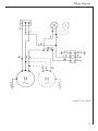 33
33
-
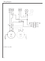 34
34
-
 35
35
-
 36
36


Zanussi ZHP622NX Manual de usuario
- Categoría
- Campanas de cocina
- Tipo
- Manual de usuario
en otros idiomas
- français: Zanussi ZHP622NX Manuel utilisateur
- italiano: Zanussi ZHP622NX Manuale utente
- English: Zanussi ZHP622NX User manual
- Deutsch: Zanussi ZHP622NX Benutzerhandbuch
- Nederlands: Zanussi ZHP622NX Handleiding
- português: Zanussi ZHP622NX Manual do usuário