Tripp Lite SmartRack SRW Serie El manual del propietario

Categoría
Bastidores
Tipo
El manual del propietario
1
Table of Contents
1. Important Safety Instructions 2
2. Overview 2
3. Feature Identification 2
4. Enclosure Installation 3
4.1 Preparation 3
4.2 Unpacking 3
4.3 Ground Connection 3
5. Enclosure Configuration 4
5.1 Door Locks 4
5.2 Cable Access and Management 4
5.3 Reversing the Enclosure 4
5.4 Mounting Rails 5
5.5 Adjusting Mounting Rail Depth 5
6. Wall Mounting the Enclosure 5
6.1 Mounting 5
7. Equipment Installation 6
7.1 Installing or Removing Cage Nuts 6
7.2 Alternate Mounting: 7
Tapped Hole Mounting Rail
8. Storage and Service 8
9. Warranty and Product Registration 8
Español 9
Francais 17
Русский 25
Swinging Wall-Mounted
SmartRack
®
Enclosures
Applies to Model Series: SRWxxUS, SRWxxUSG
(Agency Series Number: AG-00EA)
Owner’s Manual
1111 W. 35th Street, Chicago, IL 60609 USA • www.tripplite.com/support
Copyright © 2015 Tripp Lite. All trademarks are the sole property of their respective owners.
PROTECT YOUR INVESTMENT!
Register your product for quicker service and ultimate peace of mind.
You could also win an ISOBAR6ULTRA surge protector—a $100 value!
www.tripplite.com/warranty
2
1. Important Safety Instructions
3. Feature Identification
2. Overview
SAVE THESE INSTRUCTIONS
This manual contains instructions and warnings that must be followed during the installation and operation of the product described in this manual. Failure to
comply may invalidate the warranty and cause property damage or personal injury.
Keep the enclosure in a controlled indoor environment, away from moisture, temperature extremes, flammable liquids and gasses, conductive
contaminants, dust and direct sunlight.
Leave adequate space at the front and rear of the enclosure for proper ventilation. Do not block, cover or insert objects into the external ventilation
openings of the enclosure.
The enclosure is extremely heavy. Use caution when handling the enclosure. Do not attempt to unpack, move or install it unassisted. Use a
mechanical device such as a forklift or pallet jack to move the enclosure in the shipping container.
Do not place any object on the enclosure, especially containers of liquid, and do not attempt to stack the enclosures.
Inspect the shipping container and the enclosure for shipping damage. Do not use the enclosure if it is damaged.
Leave the enclosure in the shipping container until it has been moved as close to the final installation location as possible.
Install the enclosure in a structurally sound area capable of handling the load, or on a level floor that is able to bear the weight of the enclosure, all
equipment that will be installed in the enclosure and any other enclosures and/or equipment that will be installed nearby.
For permanent wall mounting, be sure to securely fasten the enclosure to the building structure before operation.
Use caution when cutting packing materials. The enclosure could be scratched, causing damage not covered by the warranty.
Save all packing materials for later use. Repacking and shipping the enclosure without the original packing materials may cause product damage
that will void the warranty.
Do not reship the enclosure with additional equipment unless the enclosure was shipped with a special shock pallet (“SP1” models only). The
combined weight of the enclosure and installed equipment must not exceed the load capacity of the pallet. Tripp Lite is not responsible for any
damage that occurs during reshipment.
Use of this equipment in life support applications where failure of this equipment can reasonably be expected to cause the failure of the life support
equipment or to significantly affect its safety or effectiveness is not recommended. Do not use this equipment in the presence of a flammable
anesthetic mixture with air, oxygen or nitrous oxide.
Swinging wall-mounted SmartRack enclosures accommodate all standard 19-inch rackmount equipment, regardless of vendor, and ship fully
assembled for quick and easy deployment. They feature adaptable, heavy-duty cabinets in various heights. All models have a hinged design that lets
the cabinet swing away from the wall bracket for easy equipment access.
Swinging wall-mounted SmartRack enclosures have variable mounting depths, ideal for servers. The cabinets include quick-release doors and side
panels for convenient maintenance. Front access doors are reversible for installation flexibility. Front door and side panels are lockable. An optional
rolling caster kit (SRCASTER) is available for easy maneuvering of enclosures.
1
Rear Door
2
Front Door
3
Horizontal Rails
4
Vertical Mounting Rails
5
Removable Cable Access Hole Covers
6
Vents
7
Locking/Removable Side Panels
Model SRW12US is shown. The other models have similar features, with the only differences being rack height and depth.
1
2
3
4
4
5
6
7
7
3
4. Enclosure Installation
4.1 Preparation
4.2 Unpacking
Caution! Read All Instructions and Warnings Before Installation!
Warning: Rack enclosures can be extremely heavy. Do not attempt to unpack, move or install the enclosure without assistance. Use
extreme caution when handling the enclosure and be sure to follow all handling and installation instructions. Do not attempt to install
equipment without first stabilizing the enclosure.
The enclosure must be installed in a structually sound area that is able to bear the weight of the enclosure, all the equipment that will be installed in
the enclosure and any other enclosures and/or equipment that will be installed nearby. Before unpacking the enclosure, you should transport the
shipping container closer to the final installation location to minimize the distance you will need to move the unit after the protective packaging has
been removed. If you plan to store the enclosure for an extended period before installation, follow the instructions in the Storage and Service section.
You need several tools:
• Level
Phillips-head screwdriver
Appropriate tools for wall mounting
You also need the following hardware:
Appropriate hardware for wall mounting (not included)
Use at least two people to unpack the enclosure.
Never extend more than one component from the enclosure at a time.
Warning: Never attempt to lift or install without adequate help.
Do not try lifting the enclosure alone.
1
Move shipping pallet to a firm, level surface.
2
Open box and remove the four foam corner protectors. Save all packing materials for later use unless you are certain they will not be required.
Packing materials are recyclable.
3
With one person on each side, carefully lift the enclosure out of the box and place on a firm, level surface.
4
Examine the enclosure for any damage or loose parts. Confirm all parts are present. If anything is missing or damaged, contact Tripp Lite for
assistance. Do not attempt to use the enclosure if it has been damaged.
4.3 Ground Connection
All parts of the enclosure are grounded to the frame of the enclosure. Use the enclosure’s front or
rear threaded grounding point
A
and an M6 screw (included) to connect the frame of the
enclosure directly to your facility’s earth ground connection with an 8 AWG (3.264 mm) wire. Route
the ground wire under the enclosure’s frame to ensure unhindered door operation. Warning:
Attach each enclosure to earth ground separately. Do not use the enclosure without an
earth ground connection.
EARTH
GROUND
A
4
5. Enclosure Configuration
5.1 Door Locks
5.2 Cable Access and Management
The front and back doors have locks that are accessible by the included keys.
Each side panel locks using an L-shaped lever on the inside of the enclosure.
1
To unlock and remove the side panels, lift the shorter leg of the “L” up
A
and pull it away from the side panel
B
. Pull the tab on the side panel
and remove it from the enclosure.
2
To re-lock the side panels, secure it in the proper position, lift the shorter leg of the “L” up
A
and push it toward the side panel, back into the hole
that it was in initially
B
. Once it is in place, push the shorter leg of the “L” down to lock it. Note: To lock and unlock the side panels, you will need
to have access to the interior of the enclosure.
The back door of the enclosure has a square opening for cable access and management. An
additonal opening can be found on top of the main cabinet. Each opening can also be closed by
screwing in the removable cable access panels.
Before installation, be sure to plan the location and arrangement of components within the enclosure. Be sure all mounting rails are reversed or
adjusted for depth, depending on your equipment configuration.
5.3 Reversing the Enclosure
In order to accommodate various rack configurations, the enclosure can be reversed. To do so, simply turn the enclosure over so that the doors open
in the opposite direction.
1 2
A
B
A
B
5
5. Enclosure Configuration
(
continued
)
6. Wall Mounting the Enclosure
5.4 Mounting Rails
6.1 Mounting
5.5 Adjusting Mounting Rail Depth
The enclosure comes with mounting rails that have both square and tapped holes for mounting rack
equipment. To install equipment, use the included cage nuts and other hardware. (See section 7.1
for installation of cage nuts.) Warning: Be sure to have the enclosure securely mounted to the
wall, or in its final position on the floor, before mounting any equipment inside. Also be
sure to have all the right adjustments on your rails before mounting equipment. (See below
for Adjusting Mounting Rail Depth.)
The number of keyhole cutouts on the back door of the enclosure will vary based on your model.
Each keyhole can accommodate an M8, M10, 5/16” or 3/8” bolt. The holes are centered 16”
apart horizontally to accommodate the standard placement of wall studs. The vertical distance
between the holes will vary based on your model.
Note: Enclosure must be installed by a qualified technician. Before mounting, use a level and tape measure
to position your mounting area precisely. Use appropriate fasteners (not included) to secure the enclosure to
the wall. A minimum of four fasteners and appropriately-sized fender washers is recommended. Use suitable
mounting means when installing to cinder block, concrete, drywall or wood studs. Warning: The supporting
surface must be able to safely support the combined load of the equipment and all attached
hardware and components. For the actual weight, size and load capacity of the enclosure, view the
product specifications and other support resources at www.tripplite.com/support.
Warning: Do not attempt to adjust rails while equipment is installed in the enclosure. Do
not attempt to use rails without screws installed. (2 per rail.)
Depending on the model, either two or four mounting rails will be pre-installed in the cabinet. The
preset mounting depth varies based on the model. Do not adjust the mounting rails unless your
equipment requires a different mounting depth. The front and rear sets of rails can be adjusted
independently in 1/4-inch (6mm) increments.
1
Each rail is connected to the enclosure with 2 screws and 2 cage nuts: 1 set in the upper
corner and another in the lower corner. Using a Phillips-head screwdriver, remove the screws
that fasten the rails to the enclosure.
2
Move cage nuts to the desired depth and reinstall.
3
Slide the mounting rails to the desired depth and reattach them using the screws you removed in
Step 1.
Warning: Do not attempt to mount the enclosure to the wall with equipment in the enclosure.
Your model’s keyhole configuration
may be different.
16”
16”
16”
16”
Variable
1
2
3
6
7. Equipment Installation
7.1 Installing or Removing Cage Nuts
Warning: Do not install equipment until you have stabilized the enclosure. Install heavier equipment first and install it towards the bottom
of the enclosure. Install equipment starting from the bottom of the enclosure and proceeding toward the top of the enclosure—never the
reverse. If using sliding equipment rails, be careful when extending the rails. Do not extend more than one set of sliding equipment rails
at one time. Avoid extending sliding equipment rails near the top of the enclosure.
Note: The unit comes with two different kinds of screws for equipment installation, black and silver. Use the black mounting screws if you are securing your
equipment to the square hole side of the mounting rail. Use the silver screws if you are securing your equipment to the tapped hole side of the mounting rail.
Note: The square holes in the middle of each rack unit are numbered and also include a small notch to aid identification. A single rack unit includes the space
occupied by the numbered hole and the holes directly above and below.
To Remove Cage Nuts, Reverse Steps 1-3
Note: You may wish to use a cage nut tool (user-supplied) to aid cage nut installation and removal.
WARNING: The flanges of the cage nuts should engage the sides of the square opening in the rail, not the top and bottom. Follow the
instructions in your equipment documentation to ensure proper installation of your equipment.
1
Locate the numbered square openings in the mounting rails where you plan to install your
equipment. You will install cage nuts (included) into the square openings in order to provide an
attachment point for the mounting screws (included). Note: Consult your equipment
documentation to determine how many cage nuts will be required and where they will need to
be installed.
2
From the inside of the mounting rail, insert one of the flanges of the cage nut through the
square opening. Press it against the side of the square opening. Each flange should engage one
side of the square opening, not the top or bottom.
3
Compress the cage nut at the sides slightly to allow the remaining flange to fit through the
square opening. When the cage nut is properly installed, both flanges will protrude through the
square opening and will be visible on the outer surface of the mounting rail. Repeat steps 1-3
until all required cage nuts are installed.
4
After installing the required cage nuts, use the included black mounting screws and cup washers
to secure your equipment to the rack rail. Place the cup washers between the screws and the
equipment mounting brackets.
Note: Your equipment may also include mounting hardware. Read the mounting instructions that came
with your equipment before installing your equipment.
2
19
18
22
3
1
2
19
18
22
3
2
2
19
18
22
3
3
2
1
18
22
3
4
24
25
26
27
28
29
23
22
21
20
19
18
24
25
26
27
28
29
23
22
21
20
19
18
2
4
24
2
1 Rack Unit
7
7. Equipment Installation
(
continued
)
7.2 Alternate Mounting: Tapped Hole Mounting Rail
WARNING: Do not attempt to adjust rails while equipment is installed in the enclosure. Do not attempt to use rails without screws
installed. (2 per rail.)
The 2 mounting rails are pre-installed for securing equipment using the square hole side of the mounting rail. To switch to the tapped hole side of the
mounting rail, follow the steps below:
1
Each rail is connected to the enclosure with 2 screws: 1 in the upper corner and another in the
lower corner. Using a Phillips-head screwdriver, remove the screws that fasten the rails to the
enclosure.
2
Switch the rail locations. Ensure the tapped hole side of each rail is facing the front door.
3
Reattach the mounting rails.
4
Use the included silver mounting screws to secure your equipment to the rack rail. Place the
cup washers between the screws and the equipment mounting brackets.
Note: Your equipment may also include mounting hardware. Read the mounting instructions that came
with your equipment before installing your equipment.
1
3
Upper Rail
Upper Rail
Lower Rail
Lower Rail
2
2
4
8
5-Year Limited Warranty
Seller warrants this product, if used in accordance with all applicable instructions, to be free from original defects in material and workmanship for a period of
5 years from the date of initial purchase. If the product should prove defective in material or workmanship within that period, Seller will repair or replace the
product, at its sole discretion.
THIS WARRANTY DOES NOT APPLY TO NORMAL WEAR OR TO DAMAGE RESULTING FROM ACCIDENT, MISUSE, ABUSE OR NEGLECT. SELLER MAKES NO
EXPRESS WARRANTIES OTHER THAN THE WARRANTY EXPRESSLY SET FORTH HEREIN. EXCEPT TO THE EXTENT PROHIBITED BY APPLICABLE LAW, ALL IMPLIED
WARRANTIES, INCLUDING ALL WARRANTIES OF MERCHANTABILITY OR FITNESS, ARE LIMITED IN DURATION TO THE WARRANTY PERIOD SET FORTH ABOVE;
AND THIS WARRANTY EXPRESSLY EXCLUDES ALL INCIDENTAL AND CONSEQUENTIAL DAMAGES. (Some states do not allow limitations on how long an implied
warranty lasts, and some states do not allow the exclusion or limitation of incidental or consequential damages, so the above limitations or exclusions may not
apply to you. This warranty gives you specific legal rights, and you may have other rights which vary from jurisdiction to jurisdiction).
WARNING: The individual user should take care to determine prior to use whether this device is suitable, adequate or safe for the use intended. Since individual
applications are subject to great variation, the manufacturer makes no representation or warranty as to the suitability or fitness of these devices for any specific
application.
Product Registration
Visit www.tripplite.com/warranty today to register your new Tripp Lite product. You’ll be automatically entered into a drawing for a chance to win a FREE Tripp Lite
product!*
* No purchase necessary. Void where prohibited. Some restrictions apply. See website for details.
Tripp Lite has a policy of continuous improvement. Specifications are subject to change without notice.
8. Storage and Service
9. Warranty and Product Registration
Storage
The enclosure should be stored in a controlled indoor environment, away from moisture, temperature extremes, flammable liquids and gasses,
conductive contaminants, dust and direct sunlight. Store the enclosure in its original shipping container if possible.
Service
Your Tripp Lite product is covered by the warranty described in this manual. A variety of Extended Warranty and On-Site Service Programs are also
available from Tripp Lite. For more information on service, visit www.tripplite.com/support. Before returning your product for service, follow these steps:
1. Review the installation and operation procedures in this manual to insure that the service problem does not originate from a misreading of the
instructions.
2. If the problem continues, do not contact or return the product to the dealer. Instead, visit www.tripplite.com/support.
3. If the problem requires service, visit www.tripplite.com/support and click the Product Returns link. From here you can request a Returned Material
Authorization (RMA) number, which is required for service. This simple on-line form will ask for your unit’s model and serial numbers, along with
other general purchaser information. The RMA number, along with shipping instructions will be emailed to you. Any damages (direct, indirect, special
or consequential) to the product incurred during shipment to Tripp Lite or an authorized Tripp Lite service center is not covered under warranty.
Products shipped to Tripp Lite or an authorized Tripp Lite service center must have transportation charges prepaid. Mark the RMA number on the
outside of the package. If the product is within its warranty period, enclose a copy of your sales receipt. Return the product for service using an
insured carrier to the address given to you when you request the RMA.
1111 W. 35th Street, Chicago, IL 60609 USA • www.tripplite.com/support
9
Índice
1. Instrucciones de 10
Seguridad Importantes
2. Vista General 10
3. Identificación de Características 10
4. Instalación del Gabinete 11
4.1 Preparación 11
4.2 Desempacado 11
4.3 Conexión a Tierra 11
5. Configuración del Gabinete 12
5.1 Cerraduras de la Puerta 12
5.2 Acceso y Administración 12
del Cableado
5.3 Invirtiendo el Gabinete 12
5.4 Rieles para Instalación 13
5.5 Ajuste de Profundidad 13
del Riel de Instalación
6. Instalando el gabinete en la pared 13
6.1 Instalación 13
7. Instalación del Equipo 14
7.1 Instalación o Remoción de 14
las Tuercas de Fijación
7.2 Instalación Alterna: Riel de 15
Instalación con Orificio Roscado
8. Almacenamiento y Servicio 16
9. Garantía 16
English 1
Francais 17
Русский 25
Gabinetes SmartRack
®
Giratorios
para Instalar en la Pared
Aplica a Modelos Serie: SRWxxUS, SRWxxUSG
(Número de Serie de Agencia: AG-00EA)
Manual del Propietario
1111 W. 35th Street, Chicago, IL 60609 USA • www.tripplite.com/support
Copyright © 2015 Tripp Lite. Todas las otras marcas registradas son propiedad de sus respectivos dueños.
10
1. Instrucciones de Seguridad Importantes
3. Identificación de Características
2. Vista General
CONSERVE ESTAS INSTRUCCIONES
Este manual contiene instrucciones y advertencias que deben observarse durante la instalación y operación del producto descrito en este manual. El no
hacerlo puede invalidar la garantía y causar daños a la propiedad o lesiones personales.
Mantenga el gabinete en un entorno interior controlado lejos de humedad excesiva, temperaturas extremas, líquidos y gases inflamables,
contaminantes conductores, polvo o luz solar directa.
Deje un espacio adecuado al frente y detrás del gabinete para una ventilación adecuada. No bloquee, cubra o inserte objetos en las aberturas de
ventilación externa del gabinete.
El gabinete es extremadamente pesado. Tenga cuidado al manejar el gabinete. No intente desempacarlo, moverlo o instalarlo sin ayuda. Use un
dispositivo mecánico como un montacargas o gato para tarimas para mover el gabinete en el contenedor de embarque.
No coloque objeto alguno sobre el gabinete, especialmente recipientes de líquidos y no intente apilar los gabinetes.
Inspeccione el contenedor de embarque y el gabinete para detectar daños en el embarque. No use el gabinete si está dañado.
Deje el gabinete en el contenedor de embarque hasta que haya sido movido tan cerca a su ubicación final como sea posible.
Instale el gabinete en un área estructuralmente firme, capaz de manejar la carga o sobre una piso nivelado que sea capaz de soportar el peso del
gabinete, todo el equipo que se instale en el gabinete y otros gabinetes y/o equipo que se instalen cerca.
Para instalación permanente en la pared, asegúrese de fijar firmemente el gabinete a la estructura del edificio antes de la operación.
Tenga cuidado al cortar los materiales de empaque. El gabinete podría ser arañado, causando daños no cubiertos por la garantía.
Guarde todo el material de empaque para uso posterior. El reempacar y embarcar el gabinete sin los materiales de empaque originales puede
causar daños al producto que anulen la garantía.
No reembarque el gabinete con equipo adicional a menos que el gabinete haya sido embarcado con una tarima especial anti-impacto (solo
modelos “SP1”). El peso combinado del gabinete y el equipo instalado no debe exceder la capacidad de la tarima. Tripp Lite no es responsable por
daño alguno que ocurra durante el reembarque.
No se recomienda el uso de este equipo en aplicaciones de soporte de vida en donde la falla de este equipo pueda consecuentemente causar la
falla del equipo de soporte de vida o afectar significativamente su seguridad o efectividad. No use este equipo en presencia de una mezcla
inflamable de anestésicos con aire, oxígeno u óxido nitroso.
Los gabinetes SmartRack giratorios para Instalación en la Pared acomodan todo el equipo para instalación en rack estándar de 19", sin importar el
proveedor y se embarcan completamente ensamblados para una instalación rápida y fácil. Presentan gabinetes adaptables de servicio pesado en
diversas alturas. Todos los modelos tienen un diseño abisagrado que permite al gabinete girar alejándose del soporte de pared para un fácil acceso al
equipo.
Los gabinetes SmartRack giratorios para instalación en la pared tienen profundidades variables de instalación, ideales para servidores. Para comodidad
en el mantenimiento, los gabinetes incluyen puertas y paneles laterales de liberación rápida. Para flexibilidad de instalación, las puertas de acceso
frontal son reversibles. La puerta frontal y los paneles laterales pueden cerrarse con cerradura. Para fácil movilidad de los gabinetes está disponible un
juego opcional de ruedas (SRCASTER).
1
Puerta Posterior
2
Puerta delantera
3
Rieles Horizontales
4
Rieles para Instalación Vertical
5
Cubierta removible para el agujero de acceso de los cables
6
Ventilas
7
Paneles Laterales Removibles/con Cerradura
Se muestra el modelo SRW12US. Los otros modelos tienen características similares, con las únicas diferencias en la altura y profundidad del rack.
1
2
3
4
4
5
6
7
7
11
4. Instalación del Gabinete
4.1 Preparación
4.2 Desempacado
¡Precaución!
¡Lea todas las instrucciones y advertencias antes de la instalación!
Advertencia: Los gabinetes de rack son extremadamente pesados. No intente desempacar, mover o instalar el gabinete si ayuda. Tenga
extremo cuidado al manejar el gabinete y cerciórese de seguir todas las instrucciones de instalación. No intente instalar el equipo sin
estabilizar primero el gabinete.
El gabinete debe instalarse en un área estructuralmente firme que sea capaz de soportar el peso del gabinete, todo el equipo que se instale en el
gabinete y otros gabinetes y/o equipo que se instalen cerca. Antes de desempacar el gabinete, debe transportar el contenedor de embarque lo más
cerca posible a la posición de instalación final para minimizar la distancia que necesite mover la unidad después de haber retirado el empacado
protector. Si planea almacenar el gabinete por un período prolongado antes de la instalación, siga las instrucciones en la sección Almacenamiento y
Servicio.
Necesita varias herramientas:
• Nivel
• Desarmador con punta Phillips
• Herramientas apropiadas para instalación en pared:
Necesita además los siguientes accesorios:
Accesorios apropiados para instalación en pared
(no incluidos)
Utilice al menos dos personas para desempacar el gabinete.
Nunca extienda más de un componente del gabinete a la vez.
Advertencia: Nunca intente levantar o instalar sin la ayuda adecuada.
No trate de levantar el gabinete solo.
1
Mueva la tarima de embarque a una superficie firme y nivelada.
2
Abra la caja y retire los cuatro protectores de las esquinas. Guarde todos los materiales de empaque para uso posterior a menos que esté seguro de no
necesitarlos. Los materiales de empaque son reciclables.
3
Con una persona en cada lado, levante cuidadosamente el gabinete fuera de la caja y colóquelo sobre una superficie firme y nivelada.
4
Examine el gabinete para detectar cualquier daño o parte suelta. Confirme que estén todas las partes. Si falta algo o está dañado, póngase en
contacto con Tripp Lite para solicitar apoyo. No intente usar el gabinete si ha sido dañado.
4.3 Conexión a Tierra
Todas las partes del gabinete se conectan a tierra con el marco del gabinete. Use el punto roscado
de conexión a tierra frontal o posterior
A
y un tornillo M6 (incluido) para conectar el marco del
gabinete directamente a la conexión de tierra de su instalación con un cable calibre 8 AWG (3.264
mm). Conduzca el cable de tierra bajo el marco del gabinete para asegurar la operación sin
obstáculos de la puerta. Advertencia: Conecte cada gabinete por separado a la conexión a
tierra física. No use el gabinete sin una conexión a tierra física.
EARTH
GROUND
A
TIERRA
FÍSICA
12
5. Configuración del Gabinete
5.1 Cerraduras de la Puerta
5.2 Acceso y Administración del Cableado
La puertas frontal y posterior tienen cerraduras que son accesibles con las llaves incluidas.
Cada panel lateral se asegura usando una palanca en "L" en el lado interno del gabinete.
1
Para desasegurar y remover los paneles laterales, levante el lado corto de la “L
A
retírela del panel lateral
B
. Jale la pestaña en el panel lateral
y remuévala del gabinete.
2
Para colocar nuevamente los paneles laterales, asegúrelos es una posición correcta, levante el lado corto de la “L
A
y presiónela hacia el panel
lateral, nuevamente al orificio en donde estaba inicialmente
B
. Una vez en su sitio, oprima el lado corto de la "L" para asegurarla. Nota: Para
asegurar y desasegurar los paneles laterales, usted necesitará tener acceso al interior del gabinete.
La puerta posterior del gabinete tiene una abertura cuadrada para acceso y administración del
cableado. Puede encontrarse una abertura adicional en la parte superior del gabinete principal.
Cada abertura puede además ser cerrada atornillando los paneles removibles de acceso de cables.
Antes de la instalación, asegúrese de planear la ubicación y arreglo de los componentes dentro del gabinete. Asegure que los rieles de instalación
estén invertidos o ajustados para la profundidad, dependiendo de la configuración de su equipo.
5.3 Invirtiendo el Gabinete
A fin de disponer varias configuraciones de rack, el gabinete puede ser invertido. Para hacerlo, simplemente gire el gabinete de modo que las puertas
abran en direcciones opuestas.
1 2
A
B
A
B
13
5. Configuración del Gabinete
(continuación)
6. Instalando el gabinete en la pared
5.4 Rieles para Instalación
6.1 Instalación
5.5 Ajuste de Profundidad del Riel de Instalación
El gabinete viene con rieles de instalación que tienen orificios cuadrados y orificios roscados para
equipo de instalación en rack. Para instalar el equipo, use las tuercas de fijación incluidas y otros
accesorios. (sección 7.1 para instalación de tuercas de fijación). Advertencia: Antes de montar
cualquier equipo dentro, asegúrese de tener el gabinete instalado firmemente en la pared
o en su posición final sobre el piso. Asegúrese además de tener todos los ajustes
correctos en sus rieles antes de instalar el equipo. (Para el Ajuste de Profundidad del Riel
de Instalación, vea abajo).
El número de perforacionas del gabinete en la puerta posterior variarán según el modelo. Cada
abertura puede aceptar un perno M8, M10, 5/16" o 3/8”. Los orificios están centrados con 16"
entre sí para acomodar la colocación estándar de pernos de pared. La distancia vertical entre los
orificios variará según el modelo.
Note: El gabinete debe ser instalado por un técnico calificado. Antes de instalar, use un nivel y cinta
métrica para ubicar con precisión su área de instalación. Use sujetadores adecuados (no incluidos) para
asegurar el gabinete a la pared. Se recomienda un mínimo de cuatro tornillos y arandelas del tamaño
apropiado. Use los medios adecuados de soporte al instalar a bloques de concreto, concreto, tabla-roca o
travesaños de madera. Advertencia: La superficie de apoyo debe ser capaz de soportar con
seguridad la carga combinada de todo el hardware y componentes instalados. Para el peso,
tamaño y capacidad real de carga del gabinete, vea las especificaciones del producto y otros
recursos de soporte en www.tripplite.com/support.
Advertencia: No intente ajustar los rieles mientras el equipo está instalado en el gabinete.
No intente usar rieles sin los tornillos instalados. (2 por riel.)
Dependiendo del modelo, dos o cuatro rieles de instalación estarán preinstalados en el gabinete.
La profundidad de instalación predeterminada varía según el modelo. No ajuste los rieles de
instalación a menos que su equipo requiera una profundidad de instalación diferente. Los juegos de
rieles anterior y posterior pueden ajustarse independientemente en incrementos de 1/4" (6 mm).
1
Cada riel está conectado al gabinete con 2 tornillos y 2 tuercas de fijación: 1 juego en la
esquina superior y otro en la esquina inferior. Usando un desatornillador Phillips, retire los
tornillos que sujetan los rieles al gabinete.
2
Mueva las tuercas de sujeción a la posición deseada y reinstálelas.
3
Deslice los rieles de instalación a la profundidad deseada y reinstálelos usando los tornillos que
retiró en el Paso 1.
Advertencia: No intentar instalar el gabinete en la pared con el equipo en el gabinete.
La configuración de las perforaciones de su
modelo puede ser diferente.
16”
16”
16”
16”
Variable
1
2
3
Variable
14
7. Instalación del Equipo
7.1 Instalación o Remoción de las Tuercas de Fijación
Advertencia: No instale equipos hasta haber estabilizado el gabinete. Instale primero el equipo más pesado haca la parte inferior del
gabinete. Instale el equipo empezando por la parte inferior del gabinete y continúe hacia la parte superior del gabinete - nunca al revés.
Si se usan rieles deslizantes de equipo, tenga cuidado al extender los rieles. No extienda más de un juego de rieles deslizantes de equipo
a la vez. Evite extender los rieles deslizantes del equipo cerca de la parte superior del gabinete.
Nota: La unidad viene con dos diferentes clases de tornillos para la instalación del equipo. Use los tornillos de instalación negros si está sujetando su equipo al
lado del orificio cuadrado del riel de instalación. Use los tornillos plateados si está sujetando su equipo al lado del orificio roscado del riel de instalación.
Nota: Los orificios cuadrados en medio de cada unidad de rack están numerados y también incluyen una pequeña ranura para ayudar a la identificación. Una
sola unidad de rack incluye el espacio ocupado por el orificio numerado y los orificios directamente arriba y abajo.
Para Retirar las Tuercas de Fijación, Invierta los Pasos 1-3
Nota: Usted puede desear usar una herramienta para tuerca de fijación (proporcionada por el usuario)
para ayudar en la instalación y desinstalación de la tuerca de fijación.
ADVERTENCIA: Las bridas de las tuercas de fijación deben acoplar con los costados de la abertura del orificio cuadrado en el riel, no en
la parte superior o inferior. Siga las instrucciones en la documentación de su equipo para asegurar la instalación adecuada de su equipo.
1
Localice las aberturas cuadradas numeradas en los rieles de instalación en donde planee
instalar su equipo. Instalará tuercas de fijación (incluidas) en las aberturas cuadradas a fin de
proporcionar un punto de fijación para los tornillos de instalación (incluidos). Nota: Consulte la
documentación de su equipo para determinar cuántas tuercas de fijación requerirá y en dónde
necesitan instalarse.
2
Desde la parte interior del riel de instalación, inserte una de las bridas de la tuerca de fijación a
través de la abertura cuadrada. Oprímala hacia el costado de la abertura cuadrada. Cada brida
debe acoplar en un costado de la abertura cuadrada, no en la parte superior o inferior.
3
Comprima la tuerca de fijación ligeramente por los costados para permitir que el resto de la
brida se acople a través de la abertura cuadrada. Cuando la tuerca de fijación esté instalada
correctamente, ambas bridas deben sobresalir a través de la abertura cuadrada y ser visibles
sobre la superficie exterior del riel de instalación. Repita los pasos 1-3 hasta que estén
instaladas todas las tuercas de fijación necesarias.
4
Después de instalar las tuercas de fijación, use los tornillos de instalación negros incluidos y
arandelas de seguridad para fijar su equipo al riel del rack. Coloque las arandelas de seguridad
entre los tornillos y las ménsulas de instalación del equipo.
Nota: Su equipo puede incluir también accesorios para instalación. Lea las instrucciones de instalación
que vienen con su equipo antes de instalar su equipo.
2
19
18
22
3
1
2
19
18
22
3
2
2
19
18
22
3
3
2
1
18
22
3
4
24
25
26
27
28
29
23
22
21
20
19
18
24
25
26
27
28
29
23
22
21
20
19
18
2
4
24
2
1 Rack Unit
Unidad de Rack
15
7. Instalación del Equipo
(continuación)
7.2 Instalación Alterna: Riel de Instalación con Orificio Roscado
ADVERTENCIA: No intente ajustar los rieles mientras el equipo está instalado en el gabinete. No intente usar rieles sin los tornillos
instalados. (2 por riel.)
Los 2 rieles de instalación están preinstalados para asegurar el equipo usando el lado de los orificios cuadrados del riel de instalación. Para cambiar al
lado de los orificios roscados del riel de instalación, siga los pasos indicados a continuación:
1
Cada riel está conectado al gabinete con 2 tornillos: 1 en la esquina superior y otro en la
esquina inferior. Usando un desatornillador Phillips, retire los tornillos que sujetan los rieles al
gabinete.
2
Cambie las ubicaciones del riel. Cerciórese que el lado del orificio roscado vea hacia la puerta
delantera.
3
Reinstale los rieles de instalación.
4
Use los tornillos plateados de instalación, incluidos, para asegurar su equipo al riel del rack.
Coloque las arandelas de seguridad entre los tornillos y las ménsulas de instalación del equipo.
Nota: Su equipo puede incluir también accesorios para instalación. Lea las instrucciones de instalación
que vienen con su equipo antes de la instalación.
1
3
Riel Superior
Riel Superior
Riel Inferior
Riel Inferior
2
2
4
16
Garantía limitada por 5 años
El vendedor garantiza que este producto no tiene defectos originales de materiales ni de mano de obra por un período de cinco años a partir de la fecha
original de compra, si se utiliza de acuerdo con todas las instrucciones correspondientes. En caso de demostrarse dentro de ese período que el producto tiene
defectos de materiales o de mano de obra, el vendedor lo reparará o reemplazará a su exclusiva discreción.
ESTA GARANTÍA NO CUBRE EL DESGASTE NORMAL NI LOS DAÑOS CAUSADOS POR ACCIDENTES, MAL USO, ABUSO O NEGLIGENCIA. EL VENDEDOR NO
OFRECE NINGUNA GARANTÍA EXPRESA QUE NO SEA LA ESTABLECIDA EXPRESAMENTE EN EL PRESENTE DOCUMENTO. EXCEPTO EN LA MEDIDA EN QUE LO
PROHÍBAN LAS LEYES APLICABLES, LA DURACIÓN DE TODAS LAS GARANTÍAS IMPLÍCITAS, INCLUIDAS LAS DE COMERCIABILIDAD O APTITUD, SE LIMITA AL
PERÍODO DE GARANTÍA ANTES MENCIONADO Y ESTA GARANTÍA EXCLUYE EXPRESAMENTE TODOS LOS DAÑOS INCIDENTALES E INDIRECTOS. (Algunos Estados
no permiten las limitaciones a la duración de una garantía implícita y otros Estados no permiten la exclusión o limitación de los daños incidentales o indirectos,
de modo que las limitaciones o exclusiones antes mencionadas pueden no corresponder en su caso. Esta garantía le otorga derechos legales específicos y
usted puede tener otros derechos que varían de una jurisdicción a otra).
ADVERTENCIA: Antes de usar este dispositivo, cada usuario debe ocuparse de determinar si es apto, adecuado o seguro para el uso que pretende darle. Dado
que las aplicaciones individuales están sujetas a diversas variaciones, el fabricante no representa ni garantiza la idoneidad o condición de estos dispositivos
para cualquier aplicación específica.
Tripp Lite tiene una política de mejora continua. Las especificaciones están sujetas a cambio sin previo aviso.
8. Almacenamiento y Servicio
9. Garantía
Almacenamiento
El gabinete debe almacenarse en un entorno interior controlado lejos de humedad excesiva, temperaturas extremas, líquidos y gases inflamables,
contaminantes conductores, polvo o luz solar directa. De ser posible, almacene el gabinete en su contenedor de embarque original.
Servicio técnico
Su producto Tripp Lite está cubierto por la garantía descrita en este manual. Tripp Lite también pone a su disposición una variedad de Garantías
extendidas y Programas de servicio técnico en el sitio. Si desea más información sobre el servicio técnico, visite www.tripplite.com/support. Antes de
devolver su producto para servicio técnico, siga estos pasos:
1. Revise la instalación y los procedimientos de operación que se encuentran en este manual para asegurarse de que el problema de servicio no se
debe a una mala lectura de las instrucciones.
2. Si el problema persiste, no se comunique ni devuelva el producto al mayorista. En cambio, visite www.tripplite.com/support.
3. Si el problema exige servicio técnico, visite www.tripplite.com/support y haga clic en el enlace Devoluciones de productos. Desde aquí puede
solicitar un número de Autorización de Material Devuelto (RMA), que se necesita para el servicio técnico. En este sencillo formulario en línea se le
solicitarán los números de serie y modelo de la unidad, junto con otra información general del comprador. El número RMA y las instrucciones para
el envío se le enviarán por correo electrónico. La presente garantía no cubre ningún daño (directo, indirecto, especial o consecuencial) del producto
que ocurra durante el envío a Tripp Lite o a un centro de servicio técnico de Tripp Lite autorizado. Los productos enviados a Tripp Lite o a un centro
de servicio técnico de Tripp Lite autorizado deben tener prepagos los cargos de transporte. Escriba el número RMA en el exterior del embalaje. Si el
producto se encuentra dentro del período de garantía, adjunte una copia de su recibo de venta. Envíe el producto para servicio técnico mediante un
transportador asegurado a la dirección que se le proporcionó cuando solicitó el número RMA.
1111 W. 35th Street, Chicago, IL 60609 USA • www.tripplite.com/support
17
Sommaire
1. Instructions de sécurité 18
importantes
2. Vue d'ensemble 18
3. Identification des fonctionnalités 18
4. Installation de la baie 19
4.1 Préparation 19
4.2 Déballage 19
4.3 Mise à la terre 19
5. Configuration de la baie 20
5.1 Verrous de porte 20
5.2 Accès et gestion des câbles 20
5.3 Inverser la baie 20
5.4 Rails de montage 21
5.5 Réglage de la profondeur 21
du rail de montage
6. Fixation murale de la baie 21
6.1 Montage 21
7. Installation de l'équipement 22
7.1 Installation et retrait 22
des écrous cages
7.2 Autre montage : rail de montage 23
à trou taraudé
8. Stockage et entretien 24
9. Garantie 24
English 1
Español 9
Русский 25
Baies à fixation murale
oscillantes SmartRack
®
S'applique à la gamme : SRWxxUS, SRWxxUSG
(Numéro de série de l'agence : AG-00EA)
Manuel d'utilisation
1111 W. 35th Street, Chicago, IL 60609 USA • www.tripplite.com/support
Copyright © 2015 Tripp Lite. Toutes les marques de commerce appartiennent à leurs propriétaires respectifs.
18
1. Instructions de sécurité importantes
3. Identificación de Características
2. Vue d'ensemble
CONSERVEZ CES INSTRUCTIONS
Ce manuel contient des instructions et des avertissements devant être suivis pour l'installation et l'utilisation du produit décrit dans ce manuel. Le non-respect
de ces instructions peut entraîner l'annulation de la garantie et occasionner des dommages matériels ou corporels.
Maintenez la baie dans un environnement intérieur contrôlé, à l'abri de l'humidité, des températures extrêmes, des liquides et gaz inflammables,
des contaminants conducteurs, de la poussière et de la lumière directe du soleil.
Laissez un espace adéquat à l'avant et à l'arrière de la baie pour garantir une ventilation correcte. Ne pas bloquer, couvrir ou insérer des objets
dans les ouvertures de ventilation externes de la baie.
La baie est extrêmement lourde. Manipulez la baie avec précaution. N'essayez pas de déballer, déplacer ou installer l'unité sans être assisté. Utilisez
un appareil mécanique tel qu'un chariot élévateur ou un transpalette pour déplacer la baie dans le conteneur d'expédition.
Ne placez aucun objet sur la baie, en particulier pas d'objet contenant un liquide, et n'essayez jamais d'empiler les baies.
Inspectez le conteneur d'expédition et la baie à la recherche d'éventuels dégâts survenus pendant le transport. N'utilisez pas la baie si elle est
endommagée.
Laissez la baie dans le conteneur d'expédition tant que ce dernier n'a pas été déplacé aussi près que possible de l'emplacement d'installation final.
Installez la baie dans un emplacement à la structure solide et capable de supporter sa charge, ou sur un plancher capable de supporter son poids
ainsi que le poids de tous les équipements qui seront installés dans la baie et de toutes les baies et/ou de tous les équipements qui seront
installés à proximité.
Pour un montage mural permanent, veillez à fixer solidement la baie à la structure du bâtiment avant de l'utiliser.
Soyez prudent lors du découpage des éléments d'emballage. Vous pourriez rayer la baie et causer des dommages non couverts par la garantie.
Conservez l'ensemble des éléments d'emballage afin de pouvoir les réutiliser ultérieurement. Emballer et expédier la baie sans ses éléments
d'emballage d'origine peut endommager le produit et entraîner l'annulation de la garantie.
N'expédiez jamais la baie avec des équipements supplémentaires à moins que celle-ci n'ait initialement été expédiée avec une palette spéciale anti-
chocs (modèles « SP1 » uniquement). Le poids combiné de la baie et des équipements installés ne doit pas excéder la capacité de charge
maximale de la palette. Tripp Lite ne saurait être tenu responsable des dégâts survenus lors de la réexpédition.
L'utilisation de ce produit avec des dispositifs de maintien en vie n'est pas recommandée dans les cas où une panne de ce produit serait
susceptible d'entraîner une panne du dispositif de maintien en vie ou de nuire considérablement à sa sécurité ou à son efficacité. N'utilisez pas cet
équipement en présence d'un mélange anesthésique inflammable avec de l'air, de l'oxygène ou du protoxyde d'azote.
Les baies à fixation murale oscillantes SmartRack s'adaptent à toutes les marques d'équipements montés en racks 19 pouces standard et sont expédiées
entièrement assemblées pour un déploiement facile et rapide. Elles comportent des armoires robustes et réglables, de hauteurs différentes. Tous les
modèles bénéficient d'une conception à charnière permettant à l'armoire de pivoter et de s'éloigner du support mural, pour faciliter l'accès à l'équipement.
Les baies à fixation murale oscillantes SmartRack présentent des profondeurs de montage variables, ce qui les rend idéales pour les serveurs. Les
armoires comportent des portes et des panneaux latéraux à retrait rapide pour un entretien pratique. Les portes d'accès avant sont réversibles pour
une installation plus flexible. La porte avant et les panneaux latéraux sont verrouillables. Un kit optionnel de roulettes (SRCASTER) est disponible pour
faciliter le déplacement des baies.
1
Porte arrière
2
Porte avant
3
Rails horizontaux
4
Rails de montage verticaux
5
Couvercles amovibles des trous d'accès aux câbles
6
Évents
7
Panneaux latéraux amovibles/verrouillables
Le modèle SRW12US est illustré. Les autres modèles comportent des caractéristiques similaires. La seule différence concerne la profondeur et la
hauteur du rack.
1
2
3
4
4
5
6
7
7
19
4. Installation de la baie
4.1 Préparation
4.2 Déballage
Attention ! Veillez à lire l'ensemble des instructions et des
avertissements avant de commencer l'installation !
Avertissement : Les baies de rack peuvent être extrêmement lourdes. Ne tentez pas de déballer, de déplacer ou d'installer la baie sans
assistance. Soyez extrêmement prudent lors de la manipulation de la baie et veillez à bien respecter l'ensemble des instructions de
manipulation et d'installation. N'essayez pas d'installer des équipements sans stabiliser la baie au préalable.
La baie doit être installée dans un emplacement à la structure solide et capable de supporter son poids ainsi que le poids de tous les équipements qui
seront installés dans la baie et de toutes les baies et/ou de tous les équipements qui seront installés à proximité. Avant de déballer la baie, veillez à
transporter le conteneur d'expédition au plus près de l'emplacement final d'installation afin de minimiser la distance sur laquelle vous devrez déplacer
l'unité une fois l'emballage de protection retiré. Si vous prévoyez de stocker la baie pendant une période prolongée avant son installation, suivez les
instructions de la section Stockage et entretien.
Vous aurez besoin de plusieurs outils :
Niveau
Tournevis cruciforme
Outils appropriés pour le montage mural
Vous aurez également besoin du matériel suivant :
Quincaillerie adaptée pour le montage mural
(non fournie)
Prévoyez au moins deux personnes pour le déballage de la baie.
N'étendez jamais plus d'un composant de la baie à la fois.
Avertissement : N'essayez jamais de soulever ou d'installer la baie
sans assistance. N'essayez pas de soulever la baie seul.
1
Placez la palette de transport sur une surface ferme et plane.
2
Ouvrez la boîte et retirez les quatre coins de protection en mousse. Conservez l'ensemble des éléments d'emballage pour une utilisation ultérieure à moins
d'être certain qu'ils ne seront pas nécessaires. Les éléments d'emballage sont recyclables.
3
Avec une personne de chaque côté, soulevez soigneusement la baie pour la sortir de la boîte et placez-la sur une surface ferme et plane.
4
Examinez la baie à la recherche de dommages ou de pièces desserrées. Vérifiez que toutes les pièces sont présentes. Si des éléments sont manquants ou
endommagés, contactez Tripp Lite pour obtenir de l'assistance. N'essayez pas d'utiliser la baie si elle est endommagée.
4.3 Mise à la terre
Toutes les pièces de la baie sont reliées à la terre par l'intermédiaire du cadre de la baie. Utilisez le
point de mise à la terre fileté à l'avant ou à l'arrière de la baie
A
ainsi qu'une vis M6 (incluse) afin
de raccorder le cadre de la baie directement à la terre de votre installation avec un câble de calibre
8 AWG (3,264 mm). Faites passer le câble de mise à la terre sous le cadre de la baie pour ne pas
entraver l'ouverture de la porte. Avertissement : Chaque baie doit être reliée séparément à la
terre. N'utilisez pas la baie sans un raccordement à la terre.
EARTH
GROUND
A
PRISE DE
TERRE
20
5. Configuration de la baie
5.1 Verrous de porte
5.2 Accès et gestion des câbles
Les portes avant et arrière comprennent des verrous accessibles grâce aux clés fournies.
Chaque panneau latéral se verrouille à l'aide d'un levier en forme de L situé à l'intérieur de la baie.
1
Pour déverrouiller et retirer les panneaux latéraux, soulevez la partie la plus courte du « L » vers le haut
A
et retirez-la du panneau latéral
B
. Tirez
la patte du panneau latéral et retirez-le de la baie.
2
Pour verrouiller à nouveau les panneaux latéraux, mettez-les en position adéquate, soulevez la partie la plus courte du « L » vers le haut
A
et
enfoncez-la en direction du panneau latéral, dans le trou dans lequel elle se trouvait initialement
B
. Une fois en place, abaissez la partie la plus
courte du « L » afin de la verrouiller. Remarque : Pour verrouiller et déverrouiller les panneaux latéraux, vous devrez avoir accès à l'intérieur de la
baie.
La porte arrière de la baie comporte une ouverture carrée pour accéder aux câbles et les gérer. Une
ouverture supplémentaire est située sur le dessus de l'armoire principale. Chaque ouverture peut
également être fermée en vissant les panneaux amovibles d'accès aux câbles.
Avant l'installation, veillez à prévoir l'emplacement et la disposition des composants dans la baie. Veillez à inverser ou à ajuster la profondeur des rails
en fonction de la configuration de vos équipements.
5.3 Inverser la baie
Afin de l'adapter à des différentes configurations de racks, il est possible d'inverser la baie. Pour ce faire, retournez simplement la baie de manière à
ce que la porte s'ouvre dans la direction opposée.
1 2
A
B
A
B
21
5. Configuration de la baie
(
suite
)
6. Fixation murale de la baie
5.4 Rails de montage
6.1 Montage
5.5 Réglage de la profondeur du rail de montage
La baie dispose de rails de montage dotés de trous carrés et taraudés pour le montage
d'équipements en rack. Pour installer les équipements, utilisez les écrous cages et la quincaillerie
fournis (voir la section 7.1 pour l'installation des écrous cages.) Avertissement : Veillez à ce que
la baie soit solidement fixée au mur ou dans sa position définitive au sol avant de monter
des équipements à l'intérieur. Veillez également à régler vos rails de manière appropriée
avant d'installer des équipements. (Voir ci-dessous pour le réglage de la profondeur des
rails de montage.)
Le nombre de découpes de serrures de la porte arrière de la baie variera selon votre modèle.
Chaque serrure s'adapte à des boulons M8, M10, 5/16 po ou 3/8 po. Les trous sont centrés et
séparés de 16” horizontalement afin de s'adapter au placement standard des poteaux muraux. La
distance verticale entre les trous variera selon votre modèle.
Remarque : La baie doit être installée par un technicien qualifié. Avant le montage, utilisez un niveau et un
ruban à mesurer afin de positionner précisément votre surface de montage. Utilisez des fixations
appropriées (non incluses) pour bien fixer la baie au mur. Nous recommandons d'utiliser au moins quatre
fixations et rondelles de protection de taille appropriée. Utilisez des moyens de montage adaptés à
l'installation sur des blocs de béton, du ciment, des cloisons sèches ou des montants de bois.
Avertissement : La surface d'appui doit pourvoir supporter sans danger la charge combinée de
l'équipement, de toute la quincaillerie et de tous les composants attachés. Pour en savoir plus sur
la capacité de charge, la taille et le poids réels, consultez les spécifications du produit et les
autres ressources d'assistance à l'adresse www.tripplite.com/support.
Avertissement : n'essayez pas de régler les rails lorsque l'équipement est installé dans la
baie. N'essayez pas d'utiliser des rails sans avoir installé les vis (2 par rail).
Selon le modèle, deux ou quatre rails de montage seront préinstallés dans l'armoire. La profondeur
de montage prédéfinie varie selon le modèle. Ne réglez pas les rails de montage sauf si votre
équipement nécessite une profondeur de montage différente. Les ensembles de rail avant et
arrière peuvent être réglés de façon indépendante par incréments de 6 mm.
1
Chaque rail est fixé à la baie par deux vis et deux écrous cages : un ensemble dans le coin
supérieur et un autre dans le coin inférieur. À l'aide d'un tournevis cruciforme, retirez les vis
fixant les rails à la baie.
2
Déplacez les écrous cages à la profondeur souhaitée et remettez en place.
3
Faites coulisser les rails de montage à la profondeur souhaitée et refixez-les à l'aide des vis que
vous avez retirées à l'étape 1.
Avertissement : n'essayez pas de fixer la baie au mur lorsque de l'équipement se trouve à l'intérieur.
La configuration de la serrure de votre modèle
peut être différente.
16”
16”
16”
16”
Variable
1
2
3
Variable
22
7. Installation de l'équipement
7.1 Installation et retrait des écrous cages
Avertissement : N'installez pas d'équipements avant d'avoir stabilisé la baie. Commencez par installer les équipements les plus lourds en
bas de la baie. Installez les équipements en commençant par le bas de la baie et en poursuivez jusqu'en haut de la baie (ne faites jamais
l'inverse). Si vous utilisez des rails d'équipements coulissants, soyez extrêmement prudent lors de l'extension des rails. N'étendez pas plus
d'un ensemble de rails d'équipements coulissants à la fois. Évitez d'étendre des rails d'équipements coulissants près du haut de la baie.
Remarque : L'unité est livrée avec deux types différents de vis pour l'installation des équipements. Utilisez les vis de montage noires si vous fixez vos
équipements sur le côté à trous carrés du rail de montage. Utilisez les vis argentées si vous fixez vos équipements sur le côté à trous filetés du rail de montage.
Remarque : Les trous carrés au milieu de chaque unité de rack sont numérotés et sont également dotés d'une petite encoche afin d'aider à leur identification.
Une unité de rack seule comprend l'espace occupé par le trou numéroté et les trous situés directement au-dessus et en dessous.
Pour retirer les écrous cages, inversez les étapes 1-3.
Remarque : Vous souhaiterez peut-être utiliser un outil pour écrou cage (non fourni) afin de faciliter
l'installation et le retrait des écrous cages.
AVERTISSEMENT : les brides des écrous cages doivent s'engager sur les côtés de l'ouverture carrée du rail, et non pas sur la partie
supérieure ou inférieure. Suivez les instructions du manuel d'utilisation pour garantir une installation correcte de votre équipement.
1
Localisez les ouvertures carrées numérotées dans les rails de montage sur lesquels vous
prévoyez d'installer votre équipement. Vous installerez des écrous cages (inclus) dans les
ouvertures carrées de façon à créer un point de fixation pour les vis de montage (incluses).
Remarque : Consultez la documentation de votre équipement pour déterminer le nombre
d'écrous cages nécessaires et leur emplacement d'installation.
2
À partir de l'intérieur du rail de montage, insérez une des brides de l'écrou cage à travers
l'ouverture carrée. Appuyez-la contre le côté de l'ouverture carrée. Chaque bride doit s'engager
sur un côté de l'ouverture carrée, et non pas sur la partie supérieure ou inférieure.
3
Enfoncez légèrement l'écrou cage sur les côtés de façon à ce que la bride restante s'adapte à
l'ouverture carrée. Lorsque l'écrou cage est correctement installé, les deux brides dépassent de
l'ouverture carrée et sont visibles sur la surface extérieure du rail de montage. Répétez les
étapes 1 à 3 jusqu'à ce que tous les écrous cages soient installés.
4
Une fois les écrous cages requis installés, utilisez les vis de montage noires et les rondelles à
collerette pour fixer solidement vos équipements sur le rail du rack. Placez les rondelles à
collerette entre les vis et les supports de montage de l'équipement.
Remarque : Votre équipement peut également contenir le matériel de montage. Lisez attentivement les
instructions de montage de votre équipement avant de l'installer.
2
19
18
22
3
1
2
19
18
22
3
2
2
19
18
22
3
3
2
1
18
22
3
4
24
25
26
27
28
29
23
22
21
20
19
18
24
25
26
27
28
29
23
22
21
20
19
18
2
4
24
2
1 Rack Unit
Unité de rack
23
7. Installation de l'équipement
(
suite
)
7.2 Autre montage : rail de montage à trou taraudé
AVERTISSEMENT : N'essayez pas de régler les rails lorsque l'équipement est installé dans la baie. N'essayez pas d'utiliser les rails sans
avoir installé les vis (2 par rail).
Les deux rails de montage sont pré-installés afin de fixer solidement l'équipement en utilisant le côté à trous carrés du rail de montage. Pour passer
sur le côté à trous filetés du rail de montage, suivez les étapes ci-dessous :
1
Chaque rail est fixé à la baie par deux vis : une dans le coin supérieur et une autre dans le coin
inférieur. À l'aide d'un tournevis cruciforme, retirez les vis fixant les rails à la baie.
2
Inversez l'emplacement des rails. Veillez à ce que le côté à trous filetés de chaque rail soit bien
en face de la porte avant.
3
Refixez les rails de montage.
4
Utilisez les vis de montage argentées fournies afin de fixer solidement vos équipements sur le
rail du rack. Placez les rondelles à collerette entre les vis et les supports de montage de
l'équipement.
Remarque : Votre équipement peut également contenir le matériel de montage. Lisez attentivement les
instructions de montage de votre équipement avant l'installation.
1
3
Rail supérieur
Rail supérieur
Rail inférieur
Rail inférieur
2
2
4
24
Garantie limitée de 5 ans.
Le vendeur garantit que, s’il a été utilisé selon les directives applicables, ce produit est exempt de tout défaut initial de matériel et de fabrication pendant une
période de 5 ans à dater de l’achat initial. Si le produit s’avère défectueux sur le plan matériel ou de la fabrication durant cette période, le vendeur le réparera
ou le remplacera, gratuitement.
CETTE GARANTIE NE S’APPLIQUE PAS À L’USURE NORMALE OU AUX DOMMAGES DUS À UN ACCIDENT, UNE MAUVAISE UTILISATION, UN ABUS OU UNE
NÉGLIGENCE. LE VENDEUR N’ACCORDE AUCUNE GARANTIE EXPRESSE AUTRE QUE CELLE CONTENUE DANS LES DISPOSITIONS CI-DESSUS. SAUF
DISPOSITIONS CONTRAIRES PRÉVUES PAR LA LOI, TOUTES LES GARANTIES IMPLICITES, Y COMPRIS LES GARANTIES DE QUALITÉ COMMERCIALE ET
D’ADAPTATION À UN USAGE PARTICULIER, SONT LIMITÉES À LA PÉRIODE DE GARANTIE PRÉCITÉE. CETTE GARANTIE EXCLUT EXPRESSÉMENT LES DOMMAGES
ACCESSOIRES ET INDIRECTS. (Certains états n’autorisent pas les restrictions de la durée d’une garantie implicite et d’autres n’autorisent pas l’exclusion ni la
restriction des dommages accessoires ou indirects, de sorte que ces restrictions ou exclusions pourraient ne pas s’appliquer à vous. Cette garantie vous donne
des droits légaux spécifiques et vous pouvez aussi posséder d’autres droits qui varient d’une juridiction à l’autre.)
MISE EN GARDE : L’utilisateur individuel doit prendre soin de déterminer avant l’usage si cet appareil est convenable, adéquat et sûr pour l’usage prévu. Étant
donné que les applications individuelles varient énormément, le fabricant ne fait aucune déclaration, ni ne donne aucune garantie quant à la convenance de
ces appareils à une application particulière.
La politique de Tripp Lite en est une d'amélioration continue. Les spécifications sont sujettes à changement sans préavis.
8. Stockage et entretien
9. Garantie
Stockage
La baie doit être stockée dans un environnement intérieur contrôlé, à l'abri de l'humidité, des températures extrêmes, des liquides et gaz inflammables,
des contaminants conducteurs, de la poussière et de la lumière directe du soleil. Conservez la baie dans son conteneur d'expédition d'origine, si cela
est possible.
Service
Votre produit Tripp Lite est couvert par la garantie décrite dans ce manuel. Une variété de garantie prolongées et de programmes de service sur place
sont également disponibles chez Tripp Lite. Pour plus de renseignements sur le service, visitez www.tripplite.com/support. Avant de retourner votre
produit pour entretien ou réparation, suivez les étapes suivantes :
1. Relisez les directives d’installation et de fonctionnement de ce manuel afin de vous assurer que le problème n’a pas pour origine une mauvaise
lecture des directives.
2. Si le problème persiste, ne pas communiquer ou renvoyer le produit au vendeur. À la place, visitez www.tripplite.com/support.
3. Si le problème nécessite une réparation, visitez www.tripplite.com/support et cliquez sur le lien Product Returns (retour du produit). De cet endroit,
vous pouvez demander un numéro d’autorisation de retour de matériel (RMA) qui est exigé pour une réparation. Ce formulaire en ligne simple vous
demandera le numéro de modèle et le numéro de série de votre unité ainsi que d’autres renseignements généraux concernant l’acheteur. Le
numéro RMA, ainsi que les instructions concernant le transport vous seront acheminées par courriel. Tout dommage (direct, indirect, spécial ou
fortuit) survenu au produit pendant le transport à Tripp Lite ou à un centre de service autorisé Tripp Lite est exclu de la garanti. Les produits expédiés
à Tripp Lite ou à un centre de service autorisé doivent être prépayés. Inscrire le numéro RMA sur le paquet. Si le produit est encore couvert par la
garantie de deux ans, joindre une copie de votre facture d’achat. Retourner le produit pour réparation par un transporteur assuré à l’adresse qui
vous a été donnée lorsque vous avez demandé le RMA.
1111 W. 35th Street, Chicago, IL 60609 USA • www.tripplite.com/support
25
Содержание
1. Важные указания по технике 26
безопасности
2. Краткое описание 26
3. Схема расположения 26
функциональных элементов
4. Порядок установки шкафа 27
4.1 Подготовка 27
4.2 Распаковка 27
4.3 Заземление 27
5. Компоновка шкафа 28
5.1 Дверные замки 28
5.2 Отверстие для ввода кабелей и 28
оптимизация кабельных соединений
5.3 Переворачивание шкафа 28
5.4 Монтажные направляющие 29
5.5 Регулировка глубины монтажных 29
направляющих
6. Порядок настенного 29
монтажа шкафа
6.1 Монтаж 29
7. Установка оборудования 30
7.1 Установка или снятие закладных гаек 30
7.2 Альтернативный способ монтажа: 31
монтажная направляющая с
резьбовыми отверстиями
8. Хранение и техническое 32
обслуживание
9. Гарантийные обязательства 32
English 1
Español 9
Francais 17
Вращающиеся настенные
шкафы семейства SmartRack
®
Распространяется на модели серии SRWxxUS, SRWxxUSG
(Номер агентской серии: AG-00EA)
Руководство пользователя
1111 W. 35th Street, Chicago, IL 60609 USA • www.tripplite.com/support
Copyright © 2015 Tripp Lite. Все торговые марки являются исключительной собственностью их соответствующих владельцев.
26
1. Важные указания по технике безопасности
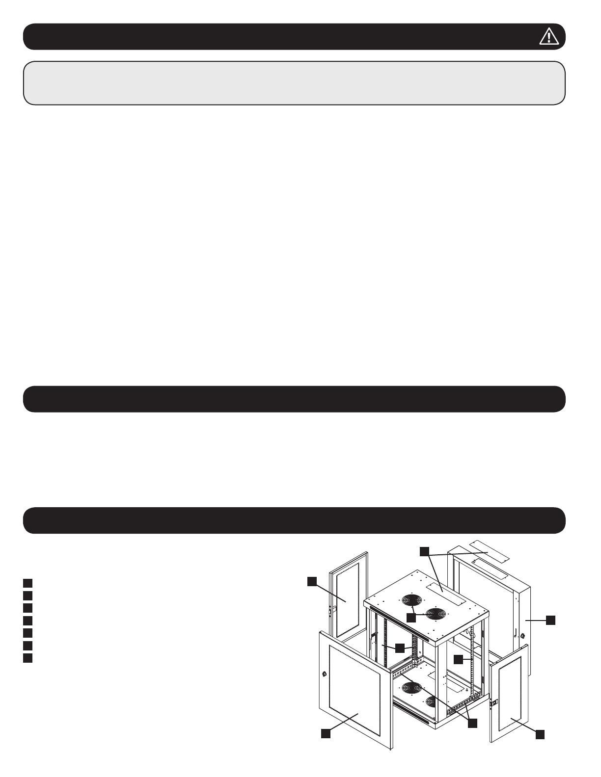
3. Схема расположения функциональных элементов
2. Краткое описание
СОХРАНИТЕ НАСТОЯЩИЕ УКАЗАНИЯ
В настоящем руководстве содержатся указания и предупреждения, которые необходимо соблюдать в процессе установки и эксплуатации описанного в нем
изделия. Несоблюдение этих указаний и предупреждений может привести к аннулированию гарантии и причинить материальный ущерб или вред здоровью людей.
Шкаф должен находиться в помещении с контролируемым микроклиматом вдали от источников влаги, экстремальных температур,
воспламеняющихся жидкостей и газов, электропроводных загрязнителей, пыли и прямого солнечного света.
Перед шкафом и позади него необходимо обеспечить достаточно свободного пространства для его надлежащего проветривания. Не загораживайте и
не накрывайте внешние вентиляционные отверстия шкафа, а также не вставляйте в них какие-либо предметы.
Шкаф является крайне тяжеловесным. При перемещении шкафа соблюдайте осторожность. Не пытайтесь распаковывать, перемещать или
устанавливать шкаф в одиночку. Для перемещения шкафа внутри транспортировочного контейнера используйте механическое устройство типа
вилочного погрузчика или вилочной гидравлической тележки.
Не кладите на шкаф какие-либо предметы, особенно емкости с жидкостями, а также не устанавливайте шкафы друг на друга.
Осмотрите транспортировочный контейнер и шкаф на предмет наличия повреждений, полученных при транспортировке. Не пользуйтесь шкафом в
случае его повреждения.
Не извлекайте шкаф из транспортировочного контейнера до его перемещения на максимально близкое расстояние к месту окончательной установки.
Шкаф должен быть установлен в конструкционно прочном месте с ровным основанием, способным выдерживать вес самого шкафа, всего
оборудования, которое будет установлено внутри него, и любых других шкафов и/или оборудования, которые будут установлены вблизи него.
Перед началом работы со шкафом обязательно прикрепите его к несущей конструкции здания.
Соблюдайте осторожность при разрезании упаковочных материалов. Это может привести к нанесению царапин на поверхность шкафа, что
представляет собой ущерб, не покрываемый действующей гарантией.
Все упаковочные материалы следует сохранить для последующего использования. Повторная упаковка и транспортировка шкафа без использования
оригинальных упаковочных материалов может привести к повреждению изделия, которое повлечет за собой аннулирование действующей гарантии.
Не допускается последующая транспортировка шкафа с дополнительным оборудованием за исключением случаев первоначальной поставки шкафа
со специальным ударозащищенным поддоном (только для моделей SP1). Суммарный вес шкафа и установленного в нем оборудования не должен
превышать грузоподъемность поддона. Компания Tripp Lite не несет ответственности за какой-либо ущерб, причиненный в процессе последующей
транспортировки.
Не рекомендуется использование данного оборудования в системах жизнеобеспечения, где его выход из строя предположительно может привести к
перебоям в работе оборудования жизнеобеспечения или в значительной мере снизить его безопасность или эффективность. Не используйте данное
оборудование в присутствии воспламеняющейся анестетической смеси с воздухом, кислородом или закисью азота.
Вращающиеся настенные шкафы семейства SmartRack вмещают в себя все стандартное 19-дюймовое оборудование независимо от его производителя
и поставляются полностью в сборе для обеспечения быстроты и легкости ввода в эксплуатацию. В состав этой серии входят адаптируемые шкафы
различной высоты с повышенной прочностью конструкции. Все модели имеют конструкцию с шарнирным креплением, позволяющую отодвигать корпус
от стены, обеспечивая удобный доступ к оборудованию.
Вращающиеся настенные шкафы семейства SmartRack имеют регулируемую глубину монтажа, что идеально подходит для установки серверов. Шкафы
комплектуются быстросъемными дверцами и боковыми панелями для удобства технического обслуживания Передние дверцы могут навешиваться на
любую сторону, что обеспечивает универсальность установки. Передняя дверца и боковые панели запираются на замок. Кроме того, возможно
приобретение опционального комплекта роликов (SRCASTER), облегчающих процесс установки монтажного шкафа в желаемое положение.
1
Задняя дверца
2
Передняя дверца
3
Горизонтальные направляющие
4
Вертикальные монтажные шины
5
Съемные заглушки отверстий для ввода кабелей
6
Вентиляционные отверстия
7
Запираемые/съемные боковые панели
На иллюстрации представлена модель SRW12US. Другие модели имеют
аналогичные функциональные элементы и отличаются только высотой и
глубиной.
1
2
3
4
4
5
6
7
7
27
4. Порядок установки шкафа
4.1 Подготовка
4.2 Распаковка
Внимание! Перед началом установки внимательно
изучите все указания и предупреждения!
Внимание! Шкаф является крайне тяжеловесным. Не пытайтесь распаковывать, перемещать или устанавливать шкаф в одиночку. Будьте
предельно осторожны при перемещении шкафа и обязательно следуйте всем указаниям по обращению со шкафом и его установке. Не
производите установку оборудования в шкаф до обеспечения его устойчивости.
Шкаф должен быть установлен в конструкционно прочном месте, способном выдерживать вес самого шкафа, всего оборудования, которое будет
установлено внутри него, и любых других шкафов и/или оборудования, которые будут установлены вблизи него. Перед распаковкой шкафа следует
доставить транспортировочный контейнер как можно ближе к месту окончательной установки с целью минимизации расстояния, на которое потребуется
перемещать модуль после снятия защитной упаковки. Если вы планируете хранение шкафа в течение длительного периода времени до или после
установки, следуйте указаниям, изложенным в разделе Хранение и техническое обслуживание.
Вам потребуются несколько инструментов:
Уровень
• Крестообразная отвертка
• Инструменты, используемые для настенного монтажа
Кроме того, вам потребуется следующая оснастка:
Приспособления для настенного монтажа
(в комплект поставки не входят)
Для распаковывания шкафа требуется не менее двух человек.
Ни в коем случае не извлекайте из шкафа
более одного компонента одновременно.
Внимание! Ни в коем случае не пытайтесь извлекать шкаф
из упаковки или устанавливать его без полноценной помощи.
Не пытайтесь поднимать шкаф в одиночку.
1
Переместите транспортировочный контейнер на прочную и ровную поверхность.
2
Откройте коробку и извлеките четыре угловых амортизатора из пенопласта. Все упаковочные материалы следует сохранить для последующего
использования, если вы не убеждены в том, что они более не потребуются. Упаковочные материалы подлежат вторичной переработке.
3
Расположившись по одному человеку с каждой стороны, аккуратно выньте шкаф из коробки и поместите его на прочную и ровную поверхность.
4
Осмотрите шкаф на предмет наличия каких-либо повреждений или незакрепленных деталей. Убедитесь в наличии всех деталей. В случае отсутствия или
повреждения каких-либо деталей обратитесь за помощью в компанию Tripp Lite. Не пользуйтесь шкафом в случае его повреждения.
4.3 Заземление
Все детали шкафа заземляются через его каркас. Для прямого соединения каркаса шкафа с шиной
заземления вашего объекта с помощью провода калибром 8 AWG (3,264 мм) следует использовать
переднюю или заднюю точку заземления
A
и винт M6 (поставляемый в комплекте). Для
обеспечения беспрепятственного открывания и закрывания дверцы проведите заземляющий провод
под каркасом шкафа. Внимание! Каждый шкаф должен подсоединяться к шине заземления по
отдельности. Пользование незаземленным шкафом не допускается.
EARTH
GROUND
A
ЗАЗЕМЛЕНИЕ
28
5. Компоновка шкафа
5.1 Дверные замки
5.2 Отверстие для ввода кабелей и оптимизация кабельных соединений
Передняя и задняя дверцы оснащены замками, отпираемыми с помощью входящих в комплект ключей.
Каждая из боковых панелей запирается при помощи Г-образного рычажка с внутренней стороны шкафа.
1
Для отпирания и снятия боковых панелей следует поднять вверх короткое плечо Г-образного рычажка
A
и отстранить его от боковой панели
B
.
Вынуть боковую панель из шкафа, потянув ее за язычок.
2
Для повторной фиксации боковой панели на своем месте следует установить ее в нужное положение, поднять вверх короткое плечо Г-образного
рычажка
A
и надавить на него в сторону боковой панели с целью поместить его обратно в то отверстие, где он находился первоначально
B
.
После того как короткое плечо Г-образного рычажка окажется на своем месте, следует зафиксировать его нажатием вниз. Примечание. Для
запирания и отпирания боковых панелей необходимо иметь доступ внутрь шкафа.
Задняя дверца шкафа имеет квадратное отверстие для ввода кабелей и оптимизации кабельных
соединений. В верхней панели основного корпуса имеется дополнительное отверстие. Кроме того,
каждое отверстие может быть скрыто путем ввинчивания в него съемной панели кабельного ввода.
Перед установкой шкафа обязательно следует составить план его размещения и схему расположения компонентов внутри него. Необходимо убедиться
в том, что все монтажные направляющие повернуты надлежащим образом или отрегулированы по глубине в зависимости от компоновки вашего
оборудования.
5.3 Переворачивание шкафа
Для реализации различных вариантов размещения шкафа допускается переворачивание его корпуса. Для этого следует просто перевернуть корпус
шкафа таким образом, чтобы его дверцы открывались в противоположном направлении.
1 2
A
B
A
B
29
5. Компоновка шкафа
(продолжение)
6. Порядок настенного монтажа шкафа
5.4 Монтажные направляющие
6.1 Монтаж
5.5 Регулировка глубины монтажных направляющих
Шкаф поставляется с монтажными направляющими, которые имеют как квадратные, так и
резьбовые отверстия для монтажа стоечного оборудования. Для установки оборудования следует
использовать поставляемые в комплекте закладные гайки и прочую оснастку (порядок установки
закладных гаек см. в разделе 7.1). Внимание! Перед установкой какого-либо оборудования
внутрь шкафа необходимо убедиться в том, что он надежно закреплен на стене или в другом
конечном положении. Кроме того, перед монтажом оборудования необходимо должным
образом отрегулировать все направляющие. (См. представленный ниже раздел "Регулировка
глубины монтажных направляющих").
Количество монтажных отверстий в задней дверце шкафа зависит от вашей конкретной модели.
Каждое монтажное отверстие рассчитано на болт M8, M10, 5/16” или 3/8”. Расстояние между
центрами отверстий по горизонтали составляет 16 дюймов, что обеспечивает возможность
размещения шкафа на стенах со стандартным каркасом. Расстояние между отверстиями по
вертикали зависит от вашей конкретной модели.
Примечание. Установка шкафа должна производиться только квалифицированным техническим
специалистом. Перед началом монтажа следует точно наметить место будущего расположения шкафа
с помощью уровня и рулетки. Для крепления шкафа к стене используйте подходящие для этой цели
крепежные детали (в комплект поставки не входят). Рекомендуется использовать не менее четырех
крепежных деталей с увеличенными шайбами соответствующего размера. При креплении к бетону,
шлакобетону, гипсокартону или стойкам деревянного каркаса используйте соответствующие
монтажные приспособления. Внимание! Опорная поверхность должна с запасом выдерживать
суммарную нагрузку, создаваемую оборудованием и всеми входящими в комплект деталями
оснастки и другими компонентами. См. технические характеристики изделий и другие
вспомогательные ресурсы с учетом фактического веса, размера и допустимой нагрузки шкафа
на странице www.tripplite.com/support.
Внимание: не пытайтесь регулировать направляющие при установленном в шкаф
оборудовании. Не пытайтесь использовать направляющие без установки винтов (по 2 на
каждую направляющую).
В зависимости от конкретной модели, две или четыре монтажных направляющих устанавливаются
внутрь корпуса шкафа непосредственно на заводе-изготовителе. Значение монтажной глубины,
устанавливаемой заводом-изготовителем, зависит от конкретной модели. Не регулируйте монтажные
направляющие за исключением тех случаев, когда для устанавливаемого вами оборудования
требуется другая монтажная глубина. Передняя и задняя группы направляющих могут
регулироваться независимо друг от друга с шагом 6 мм.
1
Каждая направляющая прикреплена к корпусу шкафа при помощи 2 винтов и 2 закладных гаек:
одна пара таких деталей располагается в верхнем углу, а другая – в нижнем. С помощью
крестообразной отвертки выверните винты, которые крепят направляющие к корпусу шкафа.
2
Переместите закладные гайки на желаемую глубину и установите винты на место.
3
Сдвиньте монтажные направляющие на желаемую глубину и снова закрепите их с помощью
винтов, вывернутых на Шаге 1.
Внимание! Не пытайтесь крепить шкаф к стене с находящимся внутри него оборудованием.
В вашей модели схема расположения
монтажных отверстий может быть другой.
16”
16”
16”
16”
Variable
1
2
3
Переменная
30
7. Установка оборудования
7.1 Установка или снятие закладных гаек
Внимание! Не устанавливайте оборудование до обеспечения устойчивости шкафа. Сначала следует устанавливать более тяжелое
оборудование, размещая его в нижней части шкафа. Устанавливайте оборудование начиная с низа шкафа по направлению вверх — и ни в
коем случае не наоборот. При использовании направляющих для установки оборудования соблюдайте осторожность при их выдвижении. Не
выдвигайте более одной группы направляющих одновременно. Старайтесь не выдвигать направляющие для установки оборудования,
расположенные в верхней части шкафа.
Примечание. Данный модуль поставляется в комплекте с винтами двух различных типов для монтажа оборудования. Монтажные винты черного цвета
следует использовать в том случае, если вы крепите свое оборудование к той стороне монтажной направляющей, которая снабжена квадратными
отверстиями. Монтажные винты серебристого цвета следует использовать в том случае, если вы крепите свое оборудование к той стороне монтажной
направляющей, которая снабжена резьбовыми отверстиями.
Примечание. Квадратные отверстия в середине каждого шкафа пронумерованы и имеют небольшую надсечку для удобства распознавания. В каждом
отдельном шкафу имеется место, где располагается нумерованное отверстие и отверстия, находящиеся непосредственно над и под ним.
Для извлечения закладных гаек повторите шаги 1-3 в обратном порядке
Примечание. При желании установку и извлечение закладных гаек можно производить с помощью
специального инструмента (в комплект поставки не входит).
ВНИМАНИЕ! Отгибы кромок закладных гаек должны зацепляться за боковые, а не верхний и нижний края квадратного отверстия в
направляющей. Для обеспечения правильности установки вашего оборудования следуйте указаниям, изложенным в сопроводительной
документации к нему.
1
Найдите нумерованные квадратные отверстия в монтажных направляющих, которые вы
планируете использовать для установки своего оборудования. Вставьте закладные гайки (из
комплекта) в квадратные отверстия с целью обеспечения точки крепления для монтажных
винтов (поставляемых в комплекте). Примечание. Для определения необходимого количества
закладных гаек и мест их установки ознакомьтесь с сопроводительной документацией к
вашему оборудованию.
2
Проденьте один из отгибов кромки закладной гайки через квадратное отверстие с внутренней
стороны монтажной направляющей. Вдавите ее по направлению к боковому краю квадратного
отверстия. Отгибы кромок закладных гаек должны зацепляться за боковые, а не верхний и
нижний края квадратного отверстия.
3
Слегка надавите на закладную гайку по бокам, что позволит другому отгибу кромки пройти через
квадратное отверстие. При правильной установке закладной гайки оба отгиба ее кромок
выдаются с обратной стороны квадратного отверстия и видны на внешней поверхности
монтажной направляющей. Повторяйте шаги 1-3 до тех пор, пока не будут установлены все
необходимые закладные гайки.
4
После установки необходимых закладных гаек прикрепите свое оборудование к стоечной
направляющей с помощью поставляемых в комплекте монтажных винтов черного цвета и
чашеобразных шайб. Поместите чашеобразные шайбы между винтами и монтажными
кронштейнами для крепления оборудования.
Примечание. Ваше оборудование также может поставляться в комплекте с монтажными
приспособлениями. Перед установкой своего оборудования ознакомьтесь с указаниями по монтажу,
поставляемыми в комплекте с ним.
2
19
18
22
3
1
2
19
18
22
3
2
2
19
18
22
3
3
2
1
18
22
3
4
24
25
26
27
28
29
23
22
21
20
19
18
24
25
26
27
28
29
23
22
21
20
19
18
2
4
24
2
1 Rack Unit
Стойко-место
31
7. Установка или снятие закладных гаек
(продолжение)
7.2 Альтернативный способ монтажа: монтажная
направляющая с резьбовыми отверстиями
ВНИМАНИЕ: Не пытайтесь регулировать направляющие при установленном в шкаф оборудовании. Не пытайтесь использовать
направляющие без установки винтов (по 2 на каждую направляющую).
На заводе-изготовителе 2 монтажные направляющие установлены под крепление оборудования с использованием той стороны направляющей, которая
снабжена квадратными отверстиями. Для перехода на использование той стороны монтажной направляющей, которая снабжена резьбовыми
отверстиями, необходимо выполнить следующие действия:
1
Каждая направляющая прикреплена к корпусу шкафа при помощи двух винтов, один из которых
располагается в верхнем углу, а другой – в нижнем. С помощью крестообразной отвертки
выверните винты, которые крепят направляющие к корпусу шкафа.
2
Поменяйте расположение направляющих. Убедитесь в том, что каждая из направляющих
располагается таким образом, что ее сторона с резьбовыми отверстиями обращена к передней
дверце.
3
Повторно закрепите монтажные направляющие.
4
Прикрепите оборудование к стоечным направляющим с использованием входящих в комплект
монтажных винтов серебристого цвета. Поместите чашеобразные шайбы между винтами и
монтажными кронштейнами для крепления оборудования.
Примечание. В комплект поставки вашего оборудования могут также входить монтажные
приспособления. Перед установкой оборудования ознакомьтесь с указаниями по монтажу,
поставляемыми в комплекте с ним.
1
3
Верхняя
направляющая
Верхняя
направляющая
Нижняя
направляющая
Нижняя
направляющая
2
2
4
32
15-09-216 • 93-343F_revB
Ограниченная гарантия 5 лет
Продавец гарантирует для данного продукта отсутствие дефектов в материалах и технологиях в течение 5 лет от даты первичной продажи при условии
использования его в соответствии со всеми применимыми инструкциями. В случае выявления дефектов, связанных со свойствами материала или качеством
изготовления данного изделия в течение указанного периода, продавец обязуется, по своему усмотрению, провести за свой счет его ремонт или замену.
ЭТА ГАРАНТИЯ НЕ РАСПРОСТРАНЯЕТСЯ НА НОРМАЛЬНЫЙ ИЗНОС ИЛИ ПОВРЕЖДЕНИЕ ПРОДУКТА В РЕЗУЛЬТАТЕ НЕСЧАСТНОГО СЛУЧАЯ,
НЕПРАВИЛЬНОГО ИСПОЛЬЗОВАНИЯ, НЕБРЕЖНОГО ОБРАЩЕНИЯ ИЛИ ПРЕНЕБРЕЖЕНИЯ ПРАВИЛАМИ ЭКСПЛУАТАЦИИ. ПРОДАВЕЦ НЕ ЗАЯВЛЯЕТ
НИКАКИХ ГАРАНТИЙ, КРОМЕ ЯВНО ВЫРАЖЕННЫХ ЗДЕСЬ. ЗА ИСКЛЮЧЕНИЕМ ОГРАНИЧЕНИЙ, ЗАПРЕЩЕННЫХ ДЕЙСТВУЮЩИМ ЗАКОНОДАТЕЛЬТВОМ,
ВСЕ ПОДРАЗУМЕВАЕМЫЕ ГАРАНТИИ, ВКЛЮЧАЯ ВСЕ ГАРАНИИ ПРИГОДНОСТИ К ПРОДАЖЕ ИЛИ ГОДНОСТИ ДЛЯ КОНКРЕТНОГО ПРИМЕНЕНИЯ,
ОГРАНИЧЕНЫ ПО СРОКУ ДЕЙСТВИЯ ГАРАНТИЙНЫМ ПЕРИОДОМ, УКАЗАННЫМ ВЫШЕ; И ЭТА ГАРАНТИЯ ЯВНО ИСКЛЮЧАЕТ ВСЕ СЛУЧАЙНЫЕ ИЛИ
ПОБОЧНЫЕ ПРОВРЕЖДЕНИЯ. (Применимое законодательство некоторых стран запрещает ограничение срока действия подразумеваемой гарантии; в других
странах запрещено исключение или ограничение действия гарантии в отношении случайных или последующих повреждений. В связи с этим,
вышеперечисленные ограничения и исключения действия настоящей гарантии могут оказаться неприменимыми в вашем конкретном случае. Настоящая гарантия
предоставляет вам определенные юридические права, которые могут быть дополнены другими правами в зависимости от юрисдикции).
ВНИМАНИЕ: Перед использованием настоящего изделия каждый пользователь должен самостоятельно определить степень его пригодности для
предполагаемого применения, а также степень безопасности такого применения. Так как настоящее изделие имеет множество индивидуальных применений,
производитель не дает гарантийных обязательств в отношении пригодности настоящих изделий для тех или иных конкретных применений.
Компания Tripp Lite постоянно совершенствует свою продукцию. В связи с этим возможно изменение технических характеристик без предварительного
уведомления.
8. Хранение и техническое обслуживание
9. Гарантийные обязательства
Хранение
Шкаф должен храниться в помещении с контролируемым микроклиматом вдали от источников влаги, экстремальных температур, воспламеняющихся
жидкостей и газов, электропроводных загрязнителей, пыли и прямого солнечного света. По возможности храните шкаф в его заводской транспортной
упаковке.
Сервисное обслуживание
На продукцию компании Tripp Lite дается ограниченная гарантия, условия которой изложены в настоящем руководстве. Также доступны различные
программы продлеваемой гарантии и обслуживания на объекте от компании Tripp Lite. Для получения более подробной информации о сервисном
обслуживании посетите веб-сайт компании www.tripplite.com/support. Перед возвратом продукции для обслуживания, выполните следующие действия:
1. Просмотрите инструкции по установке и эксплуатации, изложенные в настоящем руководстве, чтобы убедиться, что проблемы происходят не из-за
неправильного понимания инструкций.
2. Если проблема сохраняется, не обращайтесь и не возвращайте изделие торговому посреднику. Вместо этого посетите веб-сайт
www.tripplite.com/support.
3. Если для решения проблемы требуется ремонт, посетите веб-сайт www.tripplite.com/support и перейдите по ссылке Product Returns (возврат
продукции). Здесь можно сделать запрос о номере разрешения на возврат (RMA), который необходим для ремонта. В этой простой интерактивной
форме нужно будет заполнить номер модели устройства и его серийный номер, а также общую информацию о покупателе. Номер RMA вместе с
инструкциями по отправке будет выслан по электронной почте. Любые повреждения продукции (прямые, косвенные, умышленные или побочные),
полученные в результате транспортировки в компанию Tripp Lite или в уполномоченный сервисный центр, гарантией не покрываются.
Транспортировка продукции в компанию Tripp Lite или авторизованный сервисный центр должна быть оплачена отправителем. На внешней стороне
упаковки нанесите номер разрешения на возврат. Если продукт находится на гарантии, вложите копию чека или документа на приобретение.
Доставку продукции для обслуживания осуществляйте через застрахованных перевозчиков по адресу, полученному вместе с разрешением на
возврат.
1111 W. 35th Street, Chicago, IL 60609 USA • www.tripplite.com/support
1 / 1

Tripp Lite SmartRack SRW Serie El manual del propietario

Categoría
Bastidores
Tipo
El manual del propietario