Fortis 92690l0 Maintenance & Installation Instructions
- Categoría
- Artículos sanitarios
- Tipo
- Maintenance & Installation Instructions

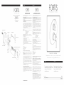
9 2 6 9 0 L 0 B R E R A
T h e r m o s t a t i c v a l v e o n l y w i t h v o l u m e c o n t r o l
T e r m o s t á t i c o c o n r e g u l a d o r d e f l u j o
For information such as installation or
care and warranty for this product, please
contact your local Fortis distributor.
www.fortisfaucet.com
Para informacion sobre la instalación, o
cuidar el producto y garantia, por favor
llama a su distribuidor local de Fortis.
www.fortisfaucet.com
01-13-2020
Copyright © 2009, Fortis
92690L0
English Español
Fortis 877 55 FORTIS - (36784) ain RDM
ewfield NJ 08344N ,
www.fortisfaucet.com
support@fortisfaucet.com
for technical support call
1-877-280-5940
English Español
LIMITED LIFETIME WARRANTY
FOR RESIDENTIAL PRODUCTS
FORTIS provides the following warranties for its products to the original
purchaser in a residential application.
MECHANICAL WARRANTY: FORTIS provides a Limited Lifetime Warranty
to all mechanical parts to be free from all manufacturing defects in materials
and workmanship under normal use for as long as the original purchaser
owns their home.
FINISH WARRANTY: FORTIS provides a Limited Lifetime Warranty on all
Fortis products to the original purchaser against manufacturing defects in
materials and workmanship.
In the event of any defect in the product breaches the foregoing warranties,
FORTIS, at its option, will replace any part or finish that proves to be
defective in material and/or workmanship, under normal installation, use
and service. Repair or replacement of the product is the exclusive remedy.
For any remedy under this warranty, FORTIS, is to be notified describing the
problem. In order to notify FORTIS and receive assistance or service under
this warranty, the original purchaser may:
1. Contact by Phone: For a consumer service representative, call 1-877-
280-5940 2. Contact by Mail: Write consumer service department to the below
address: FORTIS, Inc.,
Customer Service Department
1571 North Main Road
Newfield, NJ 08344
(877) 280-5940
3. Contact by Email: Email Fortis customer service: customerservice@
fortisfaucet.com
4. Contact your Distributor: Notify the location or distributor from which the
product was purchased.
Upon contacting FORTIS, you will need to provide:
a. FORTIS product model number
b. A description of the problem
c. Your contact information (Name, Address, Phone Number)
d. Approximate Date of Purchase
In addition to the information above, to obtain a warranty repair or
replacement, you will need to provide:
1. The faulty part or product (carefully packed)
2. Proof-of-purchase (original sales receipt) from the original consumer
purchaser
FORTIS, Inc.,
Customer Service Department
1571 North Main Road
Newfield, NJ 08344
(877) 280-5940
Please allow 7 to 14 business days warranty processing.
EXCLUSIONS: This warranty does NOT cover and FORTIS will NOT
pay for:
1. Conditions, malfunctions or damage not resulting from defects in material
or workmanship
2. Conditions, malfunctions or damage resulting from any of the following:
a. Normal wear and tear, improper installation, improper maintenance,
misuse, abuse, negligence, accident or alteration
b. The use of abrasive or caustic cleaning agents or “no-rinse” cleaning
products, or the use of the product in any manner contrary to the product
instructions
c. Conditions in the home such as excessive water pressure or corrosion
3. Labor and other expenses related to disconnection, deinstallation, or
return of the product for warranty service (including but not limited to proper
packaging and shipping costs) or for installation or reinstallation of the
product
4. Accessories, connected to materials and products, or related products not
manufactured by FORTIS.
5. Any FORTIS product sold for display purposes.
WARRANTY FOR COMMERCIAL APPLICATIONS:
If the FORTIS product is installed in a commercial application, the above
mechanical warranty shall be limited for a period of (10) years and the
above finish warranty shall be limited for a period of (5) years from the date
of the purchase of the product.
Repair or replacement parts are warranted only for the period remaining
under the initial warranty. The same exclusions apply as above residential
application policy.
GARANTÍA LIMITADA DE POR VIDA
PARA PRODUCTOS DE USO RESIDENCIAL
FORTIS ofrece al comprador original las siguientes garantías para sus
productos utilizados para instalaciones residenciales.
GARANTÍA PARTES MECÁNICAS: FORTIS ofrece para todos los
componentes mecánicos una Garantía Limitada de por vida que cubre los
defectos de fabricación en los materiales y elaboración, en condiciones de
uso normales, hasta que el comprador original sea propietario del inmueble
donde se instala el producto.
GARANTÍA ACABADOS: FORTIS ofrece al comprador original para todos
los productos FORTIS una Garantía Limitada de por vida que cubre los
defectos de fabricación en los materiales y la elaboración.
En caso de que un producto no fuera conforme a los parámetros de las
mencionadas garantías debido a algún defecto, FORTIS, a su exclusiva
discreción, sustituirá el componente o el acabado defectuoso en el
material y/o la elaboración en normales condiciones de instalación,
uso y mantenimiento. La única solución admitida será la reparación o la
sustitución del producto.
Para hacer valer cualquier tipo de cobertura prevista por la garantía el
usuario deberá enviar la solicitud a FORTIS junto con una descripción
completa del problema. Para notificar a FORTIS y recibir asistencia o un
servicio en conformidad a la presente garantía, el comprador original
podrá:
1. Llamar por teléfono: para ponerse en contacto con un representante del
servicio de atención al cliente al número 1-877-280-5940
2. Por correo: Escribir a la oficina del servicio de atención al cliente a la
siguiente dirección: FORTIS, Inc.,
Customer Service Department
1571 North Main Road
Newfield, NJ 08344
(877) 280-5940
3. Por email: Email del servicio de atención al cliente FORTIS:
customerservice@fortisfaucet.com 4. Contactar a nuestro distribuidor: Comunicar el lugar o el distribuidor
donde ha sido comprado el producto.
Después de haberse puesto en contacto con FORTIS, deberán indicar:
a. El número del modelo del producto FORTIS
b. Una descripción del problema
c. Las informaciones para contactarles (nombre, dirección, número de
teléfono)
d. Fecha de compra aproximada
Para poder recibir asistencia para la reparación o sustitución en garantía,
además de las informaciones anteriormente mencionadas, deberán enviar
lo siguiente:
1. El componente o producto defectuoso (cuidadosamente embalado)
2. El comprobante de compra (recibo de compra original) que el comprador
original del producto posee.
FORTIS, Inc.,
Customer Service Department
1571 North Main Road
Newfield, NJ 08344
(877) 280-5940
Para la elaboración de la solicitud de aplicación de la garantía serán
necesarios de 7 a 14 días laborales.
EXCEPCIONES: La presente garantía NO cubre y FORTIS NO pagará
por:
1. Las condiciones, los malfuncionamientos o los daños que no sean debidos
a defectos de material o elaboración
2. Las condiciones, los malfuncionamientos o los daños debidos a uno de los
siguientes casos:
a. Normal desgaste, instalación incorrecta, mantenimiento incorrecto, uso
impropio, abuso, negligencia, accidente o alteración
b. Uso de agentes abrasivos o productos de limpieza corrosivos o que no
necesitan enjuague, o uso impropio del producto contrario a las indicaciones
c. Condiciones del inmueble producidas por excesiva presión del agua o
corrosión
3. Mano de obra y otros gastos relativos a la desconexión, desmontaje
o restitución del producto por servicios de garantía (incluso el embalaje
adecuado y los costos de expedición) o por la instalación o el desmontaje
del producto. 4. Accesorios, relacionados con los materiales y productos, o relativos a
productos no fabricados por FORTIS.
5. Los productos FORTIS vendidos exclusivamente con fines de exposición.
GARANTÍA PARA USOS COMERCIALES:
En caso de que el producto FORTIS sea instalado en una unidad comercial,
la garantía para las partes mecánicas anteriormente indicada será limitada a
un período de (10) años y la garantía para los acabados será limitada a un
período de (5) años desde la fecha de compra del producto.
Las reparaciones y las piezas de repuesto están cubiertas por la garantía
sólo por el período restante de la garantía original. La misma excepción es
válida, como se indica anteriormente, para las normas aplicables al uso en
unidades residenciales.
AC92IST690THSET1UF
FR2TCC959NFUF
FR2TCC690CANMUF FR92-910TH711/FUF
FR92-910/214NUF
FR87-690RUF
FR78-710THRUF
FR81-953THSR6UF
FRUS-901AAUF
FR81-9013/4AUF
FR53CC5813/4S25UF
FR92-959/910TH711FUF

English
INSTALLATION INSTRUCTIONS
In case of pressures over 5 BAR (~75 PSI), we
recommend to use a pressure reducer.
Before proceeding with the assembly, purge the
hot and cold water pipes so as to avoid the
accumulation of dirt and impurities that could
affect the function of the faucet.
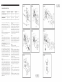
FIG. 01
Remove with a screwdriver the protection covers
(1.A). Use the plug (1.B) if necessary.
FIG. 02
Fit the faucet body to the wall with the shower
outlet pointing upwards, connect the hot water
supply to the left inlet and the cold water supply
to the right one.
The depth of the wall niche must correspond
( ) to the tolerance given wall coating included
by the MIN/MAX references given on the
plastic cover (2.A).
Once all connections have been carried out,
activate the faucet at the working pressure
(we recommend maintaining the water flow
for a few minutes so as to purge the system
from any debris and/or dirt inside the piping).
Temporarily remove the protection cover (2.A)
to check if there are leakages and if the system
works regularly, reinstall the protection cover
(2.A) and finish the external wall surface.
FIG. 03
Remove the protection cover (2.A) as shown
in FIG. 02. With a screwdriver turn the stop
cocks (3.H) clockwise, loosen the fitting screw
(3.D) using the proper wrench and pull out the
test plug (3.E). Insert the o-ring (3.C) and the
sleeve (3.B) on the thermostatic body. Fit the
o-ring (3.G) into the housing on the faucet body
and assemble the protection cylinder (3.F). Use
a small quantity of the special grease included
to lightly lubricate the o-rings of the thermostatic
cartridge (3.A). Insert the cartridge in the faucet
housing carefully aligning the positioning hole
with the housing of the fitting screw (3.D), then
tighten the latter.
Warning!, Do not force the screw (3.D).
Excessive tightening can affect the correct
function of the system or damage it. The
thermostatic cartridge is equipped with a safety
anti-scalding retainer set at 100°F (38°C). For
higher temperatures push the button on the
adjustment handle. In case of hot or cold water
pressure failure, the flow will automatically stop.
With a screwdriver loosen the stop cocks (3.H)
in anti-clockwise direction.
FIG. 04 Remove the protection tape of the adhesive
sponge (4.D) and apply it on the back of the
plate (4.C). Fit the sliding flat washers (4.B) and
(4.A) on the plate (4.C) and install it on the
thermostatic body till it is flush to the wall.
FIG. 05
Installing the control handle.
Proceed as follows for the upper part with the
stopcock:
place the shim (5.N) and the insert (5.M) on the
rod of the screw-down valve, and fix using the
screw provided (5.I), placing the washer (5.L) in
between. Place the handle (5.F) and tighten the
grub screw (5.G), then insert the plate (5.H).
Proceed as follows for the lower part with the
thermostatic cartridge:
tighten the pin (5.E) on the thermostatic cartridge
rod and mount the handle (5.A), by placing
the ring (5.D) in between, without moving the
rod as this could affect the calibration of the
cartridge. Tighten with the special grub screw
(5.B) and place the decorative plate (5.C).
FIG. 06
Proceed as follows to replace the handle (6.A)
alone:
remove the plate (6.B), unscrew the grub
screw (6.C) and pull out the handle (6.A), both
handles.
Reassemble the new handle (6.A), fix it with the
grub screw (6.C) and then insert the plate (6.B).
Water Supply Recommended Maximum Minimum
Hot Water Temperature 65 C° (~150F) 80 C° (~175F) 15 C° (~60F)
Working Pressure 3 BAR (~45PSI) 5 BAR (~75PSI) 0.5 BAR (~7PSI)
FIG. 01 FIG. 02 FIG. 06
FIG. 08FIG. 05
FIG. 07FIG. 03 FIG. 04

English
To replace the screw-down valve (6.L), remove
the plate (6.B), the grub screw (6.C) and pull
out the handle (6.A). After extracting the plate
(6.D), turn the stopcocks (6.M) clockwise, using
a screwdriver, then remove the screw (6.E), the
washer (6.F), the fitting (6.G), the shim (6.H)
and the cap (6.I). Use a wrench to unscrew
the screw-down valve (6.L) and replace it.
Reassemble everything following the same
procedure in reverse order, taking great care to
clean the surface where the seals rest.
FIG. 07
Proceed as follows to replace the handle (7.H)
alone:
remove the plate (7.F), unscrew the grub screw
(7.G) and pull out the handle (7.H).
Do not move the rod of the new cartridge (7.N),
as this could affect its calibration.
Reassemble the new handle (7.H), fix it with the
grub screw (7.G) and then insert the plate (7.F).
To replace the thermostatic cartridge (7.N),
remove the plate (7.B), the grub screw (7.C)
and pull out the handle (7.A). After removing
the plate (7.D), tighten the stopcocks (7.P)
clockwise, using a screwdriver.
Proceed as follows to replace the thermostatic
cartridge and the handle (7.E):
unscrew the fixing screw (7.O) and pull out the
thermostatic cartridge and handle (7.E) from the
faucet body. Insert the new assembly (7.E) into
the relevant slot of the faucet, taking care to
align the reference hole with the slot of the fixing
screw (7.O) that must be tightened properly
without forcing it. Overtightening could cause
malfunctions or breakages.
Proceed as follows to replace the thermostatic
cartridge (7.N) alone:
unscrew the fixing screw (7.O) and remove the
thermostatic cartridge and handle (7.E) from the
faucet body. Remove the plate (7.F) from the
assembly, unscrew the grub screw (7.G) and
pull out the handle (7.H). Remove the ring (7.I),
the locking nut (7.L) and the pin (7.M) from the
thermostatic cartridge (7.N).
Insert the new thermostatic cartridge (7.N) into
the relevant slot of the faucet, taking care to
align the reference hole with the slot of the fixing
screw (7.O) that must be tightened properly
without forcing it. Overtightening could cause
malfunctions or breakages.
Do not move the rod of the new cartridge (7.N)
Based on its policy of steady development Fortis reserves the right to change the characteristics
of the products without notice and therefore the images and data contained in this catalogue may vary.
as this could affect its calibration.
Fit the temperature locking nut (7.L) in position,
as shown in the figures, then carefully tighten
the pin (7.M), place the ring (7.I) in between
and mount the handle (7.H). Secure the handle
with the grub screw (7.G) and insert the plate
(7.F).
On completion of the operation, unscrew
the stopcocks (7.P) anticlockwise, using a
screwdriver. Refit the plate (7.D), place the
handle (7.A) in position, secure it with the grub
screw (7.C), and insert the plate (7.B).
FIG. 08
The figure shows the faucet correctly assembled.
Start the water flow by rotating handle (8.A)
by 90° clockwise, adjust the temperature using
handle (8.B).
MAINTENANCE OF THE SURFACES
Before cleaning, make sure the faucet is cold
(heat wears the surface of the faucet down). Do
not use products containing acids or corrosive
substances. Wipe the faucet daily with a soft
cloth. Do not use steel wool or metal pads,
abrasive sponges or similar products. Right
after cleaning rinse off the detergent residues
with cold water. Damages to the faucets caused
by incorrect treatment are not covered by the
warranty.

Español
INSTRUCCIONES DE INSTALACIÓN
En caso de presiones de funcionamiento
superiores a 5 bares (~75 PSI), se aconseja
el uso de un reductor de presión. Antes de
efectuar el montaje, se aconseja purgar las
tuberías del agua caliente y fría para evitar
que suciedad y pequeñas impurezas afecten el
funcionamiento del grifo.
FIG. 01 Quitar los tapones de protección (1.A) con
la ayuda de un destornillador. Utilizar, si es
necesario, el tapón (1.B).
FIG. 02 Colocar a pared el cuerpo del grifo con la
salida de la ducha hacia arriba, conectar la
alimentación del agua caliente con la entrada
izquierda y la alimentación del agua fría con
la entrada derecha.
La profundidad de empotramiento en la pared
debe respetar ( ) incluido el revestimiento
la tolerancia de las indicaciones MIN/
MAX que se encuentran en la protección de
plástico (2.A). Cuando todas las conexiones
han sido efectuadas alimentar el grifo con la
presión de funcionamiento (es recomendable
prolongar esta fase por algunos minutos para
purgar la instalación de los inevitables residuos
y/o suciedad presentes en las tuberías).
Retirar momentáneamente la protección (2.A)
para comprobar posibles pérdidas; si no se
encuentran anomalías montar nuevamente la
protección (2.A) y realizar el acabado de la
superficie externa de la pared.
FIG. 03
Retirar la protección (2.A) como se indica en
la FIG. 02. Atornillar las llaves de interrupción
(3.H) en sentido horario con la ayuda de un
destornillador, destornillar el tornillo de fijación
(3.D) utilizando la adecuada llave y extraer
el tapón de prueba (3.E) tirándolo hacia el
exterior. Introducir el o-ring (3.C) y el manguito
(3.B) en el cuerpo del termostático. Introducir
el o-ring (3.G) en el específico alojamiento
en el cuerpo del grifo y montar el capuchón
(3.F). Luego utilizar la grasa especial en
dotación para lubricar ligeramente los o-rings
del cartucho termostático (3.A). Introducirlo en
el específico alojamiento del grifo prestando
atención para hacer coincidir el orificio de
posicionamiento con el alojamiento del tornillo
de fijación (3.D), luego atornillar este último.
¡Atención!, Evitar apretar enérgicamente el
tornillo (3.D). Un apriete excesivo podría
causar malfuncionamientos o roturas.
El cartucho termostático está dotado
de dispositivo de parada de seguridad
antiquemaduras regulado en 100°F (38°C),
para obtener temperaturas más elevadas es
necesario presionar el botón que se encuentra
en la maneta de regulación. En caso de que
cese la presión del agua caliente o fría el flujo
se interrumpe automáticamente. Destornillar en
sentido antihorario las llaves de interrupción
(3.H) con la ayuda de un destornillador.
FIG. 04
Retirar la cinta protectora de la esponja
adhesiva (4.D) y aplicarla en la parte posterior
de la placa (4.C).
Posicionar las arandelas deslizantes (4.B) y
(4.A) en la placa (4.C) e instalarla en el cuerpo
termostático, apoyándola a la pared.
FIG. 05
Instalación de las manillas de mando.
Para la parte superior con llave de retención,
proceder de la manera siguiente:
colocar en la varilla de la rosca la cuña
(5.N), la pieza (5.M) y fijarla con el tornillo
(5.I) interponiendo la arandela (5.L). Colocar
después la manilla (5.F) y sujetar con la espiga
(5.G). Terminar insertando la plaqueta (5.H).
Para la parte inferior con cartucho termostático,
proceder de la manera siguiente:
Alimentación Recomendada Máxima Mínima
Temperatura agua
caliente
65 C° (~150F) 80 C° (~175F) 15 C° (~60F)
Presión de
funcionamiento
3 BARES (~45PSI) 5 BARES (~75PSI) 0.5 BARES (~7PSI)
Español
enroscar el perno (5.E) en la varilla del
cartucho termostático e instalar la manilla
(5.A) interponiendo el anillo (5.D) sin mover
la varilla, para no comprometer el calibrado
del cartucho. Apretar con la espiga de fijación
(5.B) y colocar la plaqueta de acabado (5.C).
FIG. 06
En caso de sustituir solo la manilla (6.A),
proceder de la manera siguiente:
extraer la plaqueta (6.B), destornillar la espiga
de apriete (6.C), luego extraer la manilla (6.A),
las dos manillas.
Montar la manilla nueva (6.A) y fijarla con la
espiga (6.C), completar insertando la plaqueta
(6.B).
Para la sustitución de la rosca (6.L), extraer
la plaqueta (6.B), la espiga de apriete (6.C)
y sacar la manilla (6.A). Una vez extraída la
placa (6.D), atornillar en sentido horario las
llaves de retención (6.M) con la ayuda de
un destornillador, luego desmontar el tornillo
(6.E), la arandela (6.F), el racor (6.G), la cuña
(6.H) y el capuchón (6.I). Con la ayuda de
una llave, destornillar la rosca (6.L) y sustituirla.
Prestando una particular atención a la limpieza
de las superficies en las que actúan las juntas
de estanqueidad, volver a montarlo todo
procediendo en el sentido inverso.
FIG. 07
En caso de sustituir solo la manilla (7.H),
proceder de la manera siguiente:
extraer la plaqueta (7.F), destornillar la espiga
de apriete (7.G), luego extraer la manilla (7.H).
Evitar absolutamente mover la varilla del nuevo
cartucho (7.N) para no perder el calibrado.
Montar la manilla nueva (7.H) y fijarla con la
espiga (7.G), completar insertando la plaqueta
(7.F).
Para la sustitución del cartucho termostático
(7.N), extraer la plaqueta (7.B), la espiga de
apriete (7.C) y sacar la manilla (7.A). Una vez
extraída la placa (7.D), atornillar en sentido
horario las llaves de retención (7.P) con la
ayuda de un destornillador.
En caso de sustitución del cartucho termostático
provisto de manilla (7.E), proceder de la
manera siguiente:
destornillar la espiga de fijación (7.O) y extraer
del cuerpo el cartucho termostático con la
manilla (7.E). Insertar el nuevo conjunto (7.E)
en la sede del grupo, prestando atención a que
el orificio de colocación coincida con la sede
de la espiga de fijación (7.O), y atornillar esta
última sin apretarla con demasiada fuerza. Un
apriete excesivo podría provocar problemas
de funcionamiento o roturas.
En caso de sustituir solo el cartucho termostático
(7.N), proceder de la manera siguiente:
destornillar la espiga de fijación (7.O) y
extraer del cuerpo el cartucho termostático
con la manilla (7.E). Extraer de este grupo la
plaqueta (7.F), destornillar la espiga de apriete
(7.G), luego extraer la manilla (7.H). Retirar el
cartucho termostático (7.N), el anillo (7.I), el
casquillo (7.L) y el perno (7.M).
Insertar el nuevo cartucho termostático (7.N) en
la sede del grifo, prestando atención a que el
orificio de colocación coincida con la sede de
la espiga de fijación (7.O), y atornillar esta
última sin apretarlo con demasiada fuerza. Un
apriete excesivo podría provocar problemas
de funcionamiento o roturas.
Evitar absolutamente mover la varilla del nuevo
cartucho (7.N) para no perder el calibrado.
Insertar el cartucho de fijación de temperatura
(7.L) tal como se muestra en la figura, enroscar
con precaución el perno (7.M), por último
montar la manilla (7.H) interponiendo el anillo
(7.I). Fijarlo con la espiga (7.G) y completar
insertando la plaqueta (7.F).
Una vez terminada la sustitución, desenroscar
las llaves de retención (7.P) en sentido
antihorario con la ayuda de un destornillador.
Volver a montar la placa (7.D), colocar la
manilla (7.A) y fijarla con la espiga (7.C),
luego terminar colocando la plaqueta (7.B).
FIG. 08
La figura representa el grifo montado
correctamente. La apertura del agua se efectúa
girando la maneta (8.A) 90° en sentido
horario, la temperatura se regula por medio de
la maneta (8.B).
MANTENIMIENTO DE LAS SUPERFICIES
Durante la limpieza, la superficie del grifo
debe estar fría (el calor acelera el desgaste
de la superficie misma). Asegurarse de que
los productos para la limpieza no contengan
ácidos o sustancias corrosivas. El grifo debe
ser secado diariamente con un paño suave.
Evitar absolutamente esponjas de acero,
esponjas abrasivas u otros productos similares.

Español
Por su política de continuo desarrollo, Fortis se reserva el derecho de modificar las características de los productos sin ningún aviso
previo; por tanto, las imágenes y los datos contenidos en el presente catálogo deben considerarse a título indicativo.
Inmediatamente después de la limpieza,
enjuagar bien los residuos de detergente con
agua fría. Los daños a los grifos debidos a
un tratamiento no adecuado no están cubiertos
por la garantía.
-
 1
1
-
 2
2
-
 3
3
-
 4
4
-
 5
5


Fortis 92690l0 Maintenance & Installation Instructions
- Categoría
- Artículos sanitarios
- Tipo
- Maintenance & Installation Instructions
en otros idiomas
- English: Fortis 92690l0
Artículos relacionados
-
Fortis 9440200 Maintenance & Installation Instructions
-
-
-
-
-
-
-
-
-