
Zenith

AVVERTENZE PER L’INSTALLATORE
OBBLIGHI GENERALI PER LA SICUREZZA
1) ATTENZIONE! È importante per la sicurezza delle persone seguire attenta-
mente tutta l’istruzione. Una errata installazione o un errato uso del prodotto
può portare a gravi danni alle persone.
2) Leggere attentamente le istruzioni prima di iniziare l’installazione del prodot-
to.
3) I materiali dell’imballaggio (plastica, polistirolo, ecc.) non devono essere
lasciati alla portata dei bambini in quanto potenziali fonti di pericolo.
4) Conservare le istruzioni per riferimenti futuri.
5) Questo prodotto è stato progettato e costruito esclusivamente per l’utilizzo
indicato in questa documentazione. Qualsiasi altro utilizzo non espressamen-
te indicato potrebbe pregiudicare l’integrità del prodotto e/o rappresen-
tare fonte di pericolo.
6) GENIUS declina qualsiasi responsabilità derivata dall’uso improprio o diverso
da quello per cui l’automatismo è destinato.
7) Non installare l’apparecchio in atmosfera esplosiva: la presenza di gas o fumi
infiammabili costituisce un grave pericolo per la sicurezza.
8) Gli elementi costruttivi meccanici devono essere in accordo con quanto
stabilito dalle Norme EN 12604 e EN 12605.
Per i Paesi extra-CEE, oltre ai riferimenti normativi nazionali, per ottenere un
livello di sicurezza adeguato, devono essere seguite le Norme sopra riporta-
te.
9) GENIUS non è responsabile dell’inosservanza della Buona Tecnica nella co-
struzione delle chiusure da motorizzare, nonché delle deformazioni che
dovessero intervenire nell’utilizzo.
10) L’installazione deve essere effettuata nell’osservanza delle Norme EN 12453
e EN 12445. Il livello di sicurezza dell’automazione deve essere C+E.
11) Prima di effettuare qualsiasi intervento sull’impianto, togliere l’alimentazione
elettrica.
12) Prevedere sulla rete di alimentazione dell’automazione un interruttore
onnipolare con distanza d’apertura dei contatti uguale o superiore a 3 mm.
È consigliabile l’uso di un magnetotermico da 6A con interruzione onnipolare.
13) Verificare che a monte dell’impianto vi sia un interruttore differenziale con
soglia da 0,03 A.
14) Verificare che l’impianto di terra sia realizzato a regola d’arte e collegarvi
le parti metalliche della chiusura.
15) L’automazione dispone di una sicurezza intrinseca antischiacciamento co-
stituita da un controllo di coppia. E' comunque necessario verificarne la sogli
di intervento secondo quanto previsto dalle Norme indicate al punto 10.
16) I dispositivi di sicurezza (norma EN 12978) permettono di proteggere even-
tuali aree di pericolo da Rischi meccanici di movimento, come ad Es.
schiacciamento, convogliamento, cesoiamento.
17) Per ogni impianto è consigliato l’utilizzo di almeno una segnalazione lumino-
sa nonché di un cartello di segnalazione fissato adeguatamente sulla struttu-
ra dell’infisso, oltre ai dispositivi citati al punto “16”.
18) GENIUS declina ogni responsabilità ai fini della sicurezza e del buon funziona-
mento dell’automazione, in caso vengano utilizzati componenti dell’impian-
to non di produzione GENIUS.
19) Per la manutenzione utilizzare esclusivamente parti originali GENIUS.
20) Non eseguire alcuna modifica sui componenti facenti parte del sistema
d’automazione.
21) L’installatore deve fornire tutte le informazioni relative al funzionamento
manuale del sistema in caso di emergenza e consegnare all’Utente
utilizzatore dell’impianto il libretto d’avvertenze allegato al prodotto.
22) Non permettere ai bambini o persone di sostare nelle vicinanze del prodotto
durante il funzionamento.
23) Tenere fuori dalla portata dei bambini radiocomandi o qualsiasi altro datore
di impulso, per evitare che l’automazione possa essere azionata involonta-
riamente.
24) Il transito tra le ante deve avvenire solo a cancello completamente aperto.
25) L’Utente utilizzatore deve astenersi da qualsiasi tentativo di riparazione o
d’intervento diretto e rivolgersi solo a personale qualificato.
26) Tutto quello che non è previsto espressamente in queste istruzioni non è
permesso
CONSIGNES POUR L'INSTALLATEUR
RÈGLES DE SÉCURITÉ
1) ATTENTION! Il est important, pour la sécurité des personnes, de suivre à la
lettre toutes les instructions. Une installation erronée ou un usage erroné
du produit peut entraîner de graves conséquences pour les personnes.
2) Lire attentivement les instructions avant d'installer le produit.
3) Les matériaux d'emballage (matière plastique, polystyrène, etc.) ne doivent
pas être laissés à la portée des enfants car ils constituent des sources
potentielles de danger.
4) Conserver les instructions pour les références futures.
5) Ce produit a été conçu et construit exclusivement pour l'usage indiqué dans
cette documentation. Toute autre utilisation non expressément indiquée
pourrait compromettre l'intégrité du produit et/ou représenter une source
de danger.
6) GENIUS décline toute responsabilité qui dériverait d'usage impropre ou
différent de celui auquel l'automatisme est destiné.
7) Ne pas installer l'appareil dans une atmosphère explosive: la présence de
gaz ou de fumées inflammables constitue un grave danger pour la sécurité.
8) Les composants mécaniques doivent répondre aux prescriptions des Normes
EN 12604 et EN 12605.
Pour les Pays extra-CEE, l'obtention d'un niveau de sécurité approprié exige
non seulement le respect des normes nationales, mais également le respect
des Normes susmentionnées.
9) GENIUS n'est pas responsable du non-respect de la Bonne Technique dans la
construction des fermetures à motoriser, ni des déformations qui pourraient
intervenir lors de l'utilisation.
10) L'installation doit être effectuée conformément aux Normes EN 12453 et EN
12445. Le niveau de sécurité de l'automatisme doit être C+E.
11) Couper l'alimentation électrique avant toute intervention sur l'installation.
12) Prévoir, sur le secteur d'alimentation de l'automatisme, un interrupteur
omnipolaire avec une distance d'ouverture des contacts égale ou supérieure
à 3 mm. On recommande d'utiliser un magnétothermique de 6A avec
interruption omnipolaire.
13) Vérifier qu'il y ait, en amont de l'installation, un interrupteur différentiel avec
un seuil de 0,03 A.
14) Vérifier que la mise à terre est réalisée selon les règles de l'art et y connecter
les pièces métalliques de la fermeture.
15) L'automatisme dispose d'une sécurité intrinsèque anti-écrasement, formée
d'un contrôle du couple. Il est toutefois nécessaire d'en vérifier le seuil
d'intervention suivant les prescriptions des Normes indiquées au point 10.
16) Les dispositifs de sécurité (norme EN 12978) permettent de protéger des
zones éventuellement dangereuses contre les Risques mécaniques du
mouvement, comme l'écrasement, l'acheminement, le cisaillement.
IMPORTANT NOTICE FOR THE INSTALLER
GENERAL SAFETY REGULATIONS
1) ATTENTION! To ensure the safety of people, it is important that you read
all the following instructions. Incorrect installation or incorrect use of the
product could cause serious harm to people.
2) Carefully read the instructions before beginning to install the product.
3) Do not leave packing materials (plastic, polystyrene, etc.) within reach of
children as such materials are potential sources of danger.
4) Store these instructions for future reference.
5) This product was designed and built strictly for the use indicated in this
documentation. Any other use, not expressly indicated here, could compro-
mise the good condition/operation of the product and/or be a source of
danger.
6) GENIUS declines all liability caused by improper use or use other than that for
which the automated system was intended.
7) Do not install the equipment in an explosive atmosphere: the presence of
inflammable gas or fumes is a serious danger to safety.
8) The mechanical parts must conform to the provisions of Standards EN 12604
and EN 12605.
For non-EU countries, to obtain an adequate level of safety, the Standards
mentioned above must be observed, in addition to national legal regulations.
9) GENIUS is not responsible for failure to observe Good Technique in the
construction of the closing elements to be motorised, or for any deformation
that may occur during use.
10) The installation must conform to Standards EN 12453 and EN 12445. The safety
level of the automated system must be C+E.
11) Before attempting any job on the system, cut out electrical power.
12) The mains power supply of the automated system must be fitted with an all-
pole switch with contact opening distance of 3mm or greater. Use of a 6A
thermal breaker with all-pole circuit break is recommended.
13) Make sure that a differential switch with threshold of 0.03 A is fitted upstream
of the system.
14) Make sure that the earthing system is perfectly constructed, and connect
metal parts of the means of the closure to it.
15) The automated system is supplied with an intrinsic anti-crushing safety device
consisting of a torque control. Nevertheless, its tripping threshold must be
checked as specified in the Standards indicated at point 10.
16) The safety devices (EN 12978 standard) protect any danger areas against
mechanical movement Risks, such as crushing, dragging, and shearing.
17) Use of at least one indicator-light is recommended for every system, as well
as a warning sign adequately secured to the frame structure, in addition to
the devices mentioned at point “16”.
18) GENIUS declines all liability as concerns safety and efficient operation of the
automated system, if system components not produced by GENIUS are used.
19) For maintenance, strictly use original parts by GENIUS.
20) Do not in any way modify the components of the automated system.
21) The installer shall supply all information concerning manual operation of the
system in case of an emergency, and shall hand over to the user the warnings
handbook supplied with the product.
22) Do not allow children or adults to stay near the product while it is operating.
23) Keep remote controls or other pulse generators away from children, to
prevent the automated system from being activated involuntarily.
24) Transit through the leaves is allowed only when the gate is fully open.
25) The user must not attempt any kind of repair or direct action whatever and
contact qualified personnel only.
26) Anything not expressly specified in these instructions is not permitted.

ADVERTENCIAS PARA EL INSTALADOR
REGLAS GENERALES PARA LA SEGURIDAD
1) ¡ATENCION! Es sumamente importante para la seguridad de las personas
seguir atentamente las presentes instrucciones. Una instalación incorrecta
o un uso impropio del producto puede causar graves daños a las personas.
2) Lean detenidamente las instrucciones antes de instalar el producto.
3) Los materiales del embalaje (plástico, poliestireno, etc.) no deben dejarse al
alcance de los niños, ya que constituyen fuentes potenciales de peligro.
4) Guarden las instrucciones para futuras consultas.
5) Este producto ha sido proyectado y fabricado exclusivamente para la
utilización indicada en el presente manual. Cualquier uso diverso del previ-
sto podría perjudicar el funcionamiento del producto y/o representar fuente
de peligro.
6) GENIUS declina cualquier responsabilidad derivada de un uso impropio o
diverso del previsto.
7) No instalen el aparato en atmósfera explosiva: la presencia de gas o humos
inflamables constituye un grave peligro para la seguridad.
8) Los elementos constructivos mecánicos deben estar de acuerdo con lo
establecido en las Normas EN 12604 y EN 12605.
Para los países no pertenecientes a la CEE, además de las referencias
normativas nacionales, para obtener un nivel de seguridad adecuado, deben
seguirse las Normas arriba indicadas.
9) GENIUS no es responsable del incumplimiento de las buenas técnicas de
fabricación de los cierres que se han de motorizar, así como de las
deformaciones que pudieran intervenir en la utilización.
10) La instalación debe ser realizada de conformidad con las Normas EN 12453
y EN 12445. El nivel de seguridad de la automación debe ser C+E.
11) Quiten la alimentación eléctrica antes de efectuar cualquier intervención
en la instalación.
12) Coloquen en la red de alimentación de la automación un interruptor
omnipolar con distancia de apertura de los contactos igual o superior a 3
mm. Se aconseja usar un magnetotérmico de 6A con interrupción omnipolar.
13) Comprueben que la instalación disponga línea arriba de un interruptor
diferencial con umbral de 0,03 A.
14) Verifiquen que la instalación de tierra esté correctamente realizada y
conecten las partes metálicas del cierre.
15) La automación dispone de un dispositivo de seguridad antiaplastamiento
constituido por un control de par. No obstante, es necesario comprobar el
umbral de intervención según lo previsto en las Normas indicadas en el punto
10.
16) Los dispositivos de seguridad (norma EN 12978) permiten proteger posibles
áreas de peligro de Riesgos mecánicos de movimiento, como por ej.
aplastamiento, arrastre, corte.
17) Para cada equipo se aconseja usar por lo menos una señalización luminosa
así como un cartel de señalización adecuadamente fijado a la estructura
del bastidor, además de los dispositivos indicados en el “16”.
18) GENIUS declina toda responsabilidad relativa a la seguridad y al buen
funcionamiento de la automación si se utilizan componentes de la instalación
que no sean de producción GENIUS.
19) Para el mantenimiento utilicen exclusivamente piezas originales GENIUS
20) No efectúen ninguna modificación en los componentes que forman parte
del sistema de automación.
21) El instalador debe proporcionar todas las informaciones relativas al
funcionamiento del sistema en caso de emergencia y entregar al usuario del
equipo el manual de advertencias que se adjunta al producto.
22) No permitan que niños o personas se detengan en proximidad del producto
durante su funcionamiento.
23) Mantengan lejos del alcance los niños los telemandos o cualquier otro
emisor de impulso, para evitar que la automación pueda ser accionada
involuntariamente.
HINWEISE FÜR DEN INSTALLATIONSTECHNIKER
ALLGEMEINE SICHERHEITSVORSCHRIFTEN
1) ACHTUNG! Um die Sicherheit von Personen zu gewährleisten, sollte die
Anleitung aufmerksam befolgt werden. Eine falsche Installation oder ein
fehlerhafter Betrieb des Produktes können zu schwerwiegenden
Personenschäden führen.
2) Bevor mit der Installation des Produktes begonnen wird, sollten die Anleitungen
aufmerksam gelesen werden.
3) Das Verpackungsmaterial (Kunststoff, Styropor, usw.) sollte nicht in Reichweite
von Kindern aufbewahrt werden, da es eine potentielle Gefahrenquelle
darstellt.
4) Die Anleitung sollte aufbewahrt werden, um auch in Zukunft Bezug auf sie
nehmen zu können.
5) Dieses Produkt wurde ausschließlich für den in diesen Unterlagen
angegebenen Gebrauch entwickelt und hergestellt. Jeder andere
Gebrauch, der nicht ausdrücklich angegeben ist, könnte die Unversehrtheit
des Produktes beeinträchtigen und/oder eine Gefahrenquelle darstellen.
6) Die Firma GENIUS lehnt jede Haftung für Schäden, die durch unsachgemäßen
oder nicht bestimmungsgemäßen Gebrauch der Automatik verursacht
werden, ab.
7) Das Gerät sollte nicht in explosionsgefährdeten Umgebungen installiert
werden: das Vorhandensein von entflammbaren Gasen oder Rauch stellt ein
schwerwiegendes Sicherheitsrisiko dar.
8) Die mechanischen Bauelemente müssen den Anforderungen der Normen
EN 12604 und EN 12605 entsprechen.
Für Länder, die nicht der Europäischen Union angehören, sind für die
Gewährleistung eines entsprechenden Sicherheitsniveaus neben den
nationalen gesetzlichen Bezugsvorschriften die oben aufgeführten Normen
zu beachten.
9) Die Firma GENIUS übernimmt keine Haftung im Falle von nicht fachgerechten
Ausführungen bei der Herstellung der anzutreibenden Schließvorrichtungen
sowie bei Deformationen, die eventuell beim Betrieb entstehen.
10) Die Installation muß unter Beachtung der Normen EN 12453 und EN 12445
erfolgen. Die Sicherheitsstufe der Automatik sollte C+E sein.
11) Vor der Ausführung jeglicher Eingriffe auf der Anlage ist die elektrische
Versorgung abzunehmen.
12) Auf dem Versorgungsnetz der Automatik ist ein omnipolarer Schalter mit
Öffnungsabstand der Kontakte von über oder gleich 3 mm einzubauen.
Darüber hinaus wird der Einsatz eines Magnetschutzschalters mit 6A mit
omnipolarer Abschaltung empfohlen.
13) Es sollte überprüft werden, ob vor der Anlage ein Differentialschalter mit
einer Auslöseschwelle von 0,03 A zwischengeschaltet ist.
14) Es sollte überprüft werden, ob die Erdungsanlage fachgerecht ausgeführt
wurde. Die Metallteile der Schließung sollten an diese Anlage angeschlossen
werden.
15) Die Automation verfügt über eine eingebaute Sicherheitsvorrichtung für den
Quetschschutz, die aus einer Drehmomentkontrolle besteht. Es ist in jedem
Falle erforderlich, deren Eingriffsschwelle gemäß der Vorgaben der unter
Punkt 10 angegebenen Vorschriften zu überprüfen.
16) Die Sicherheitsvorrichtungen (Norm EN 12978) ermöglichen den Schutz
eventueller Gefahrenbereiche vor mechanischen Bewegungsrisiken, wie
zum Beispiel Quetschungen, Mitschleifen oder Schnittverletzungen.
17) Für jede Anlage wird der Einsatz von mindestens einem Leuchtsignal empfohlen
sowie eines Hinweisschildes, das über eine entsprechende Befestigung mit
dem Aufbau des Tors verbunden wird. Darüber hinaus sind die unter Punkt
“16” erwähnten Vorrichtungen einzusetzen.
18) Die Firma GENIUS lehnt jede Haftung hinsichtlich der Sicherheit und des
störungsfreien Betriebs der Automatik ab, soweit Komponenten auf der
Anlage eingesetzt werden, die nicht im Hause GENIUS hergestellt wurden.
19) Bei der Instandhaltung sollten ausschließlich Originalteile der Firma GENIUS
verwendet werden.
20) Auf den Komponenten, die Teil des Automationssystems sind, sollten keine
Veränderungen vorgenommen werden.
21) Der Installateur sollte alle Informationen hinsichtlich des manuellen Betriebs
des Systems in Notfällen liefern und dem Betreiber der Anlage das
Anleitungsbuch, das dem Produkt beigelegt ist, übergeben.
22) Weder Kinder noch Erwachsene sollten sich während des Betriebs in der
unmittelbaren Nähe der Automation aufhalten.
23) Die Funksteuerungen und alle anderen Impulsgeber sollten außerhalb der
Reichweite von Kindern aufbewahrt werden, um ein versehentliches
Aktivieren der Automation zu vermeiden.
24) Der Durchgang oder die Durchfahrt zwischen den Flügeln darf lediglich bei
vollständig geöffnetem Tor erfolgen.
25) Der Betreiber sollte keinerlei Reparaturen oder direkte Eingriffe auf der
Automation ausführen, sondern sich hierfür ausschließlich an qualifiziertes
Fachpersonal wenden.
26) Alle Vorgehensweisen, die nicht ausdrücklich in der vorliegenden Anleitung
vorgesehen sind, sind nicht zulässig
17) On recommande que toute installation soit doté au moins d'une signalisation
lumineuse, d'un panneau de signalisation fixé, de manière appropriée, sur la
structure de la fermeture, ainsi que des dispositifs cités au point “16”.
18) GENIUS décline toute responsabilité quant à la sécurité et au bon
fonctionnement de l'automatisme si les composants utilisés dans l'installation
n'appartiennent pas à la production GENIUS.
19) Utiliser exclusivement, pour l'entretien, des pièces GENIUS originales.
20) Ne jamais modifier les composants faisant partie du système d'automatisme.
21) L'installateur doit fournir toutes les informations relatives au fonctionnement
manuel du système en cas d'urgence et remettre à l'Usager qui utilise
l'installation les "Instructions pour l'Usager" fournies avec le produit.
22) Interdire aux enfants ou aux tiers de stationner près du produit durant le
fonctionnement.
23) Eloigner de la portée des enfants les radiocommandes ou tout autre
générateur d'impulsions, pour éviter tout actionnement involontaire de
l'automatisme.
24) Le transit entre les vantaux ne doit avoir lieu que lorsque le portail est
complètement ouvert.
25) L'Usager qui utilise l'installation doit éviter toute tentative de réparation ou
d'intervention directe et s'adresser uniquement à un personnel qualifié.
26) Tout ce qui n'est pas prévu expressément dans ces instructions est interdit.
24) Sólo puede transitarse entre las hojas si la cancela está completamente
abierta.
25) El usuario no debe por ningún motivo intentar reparar o modificar el producto,
debe siempre dirigirse a personal cualificado.
26) Todo lo que no esté previsto expresamente en las presentes instrucciones
debe entenderse como no permitido

12
ENGLISH
AUTOMATIC SYSTEM ZENITH
Fig.1
Fig.2
328 157
Dimensions in mm
2740 (619) / 3340 (625-1225) / 3940 (1231)
1
3
4
5
6
2
415
These instructions apply to the following models:
ZENITH 619 - ZENITH 625
ZENITH 1225 - ZENITH 1231
Automatic systems ZENITH are designed to automate
overhead spring-balanced, sectional, and
counterbalanced (with special accessory) doors for
residential garages.
They consist of an electro-mechanical operator,
electronic control appliance and courtesy lamp built
into a single unit. The unit is fitted to the ceiling and
opens the door by means of a transmission chain.
The system is non-reversing and, therefore, the door
locks mechanically when the motor is not operating
and, consequently, no other lock is necessary; two
manual releases on the inside and outside (optional)
make it possible to move the door manually in case of
a power cut or fault.
Any obstacles are certain to be detected by a
controlling electronic device which comes into action
while the automatic system is in operation.
The ZENITH automatic systems were designed and built
for indoor use and for controlling vehicle access.Avoid
any other use.
1. DIMENSIONS
3. ANCILLARY ELECTRICAL EQUIPMENT
2. TECHNICAL SPECIFICATIONS
MODEL ZENITH 1225 ZENITH 1231
Power supply 230Vac 50 (60)Hz
Electric motor 24Vdc
Maximum absorbed power 350W
Maximum cycles per hour 20(with load of 56K gat 20°C)
Maximum consecutive cycles 6 (at 20°C)
Minimum distance from ceiling 35mm (Fig.4 and 5 )
Maximum available travel 2500 mm 3100 mm
Pulling/thrust power 1200N(~120Kg)
Courtesy light 230Vac 40W max
Courtesy light timer 2 minutes
Carriage speed (load free) 12 cm/sec
Deceleration speed 6 cm/sec
Deceleration travel Varies according to set-up
Door max width 5000 mm
Response time of built-in 150 msec
safety device
Door max height See max available travel
Protection class IP20
Ambient temperature -20 / +55°C
MODEL ZENITH 619 ZENITH 625
Power supply 230Vac 50 (60)Hz
Electric motor 24Vdc
Maximum absorbed power 220W
Maximum cycles per hour 20(with load of 28K gat 20°C)
Maximum consecutive cycles 6 (at 20°C)
Minimum distance from ceiling 35mm (Fig.4 and 5 )
Maximum available travel 1900 mm 2500 mm
Pulling/thrust power 600N(~60Kg)
Courtesy light 230Vac 40W max
Courtesy light timer 2 minutes
Carriage speed (load free) 12 cm/sec
Deceleration speed 6 cm/sec
Deceleration travel Varies according to set-up
Door max width 3000 mm
Response time of built-in 150 msec
safety device
Door max height See max available travel
Protection class IP20
Ambient temperature -20 / +55°C
4) Power pipe (230V)
2) Cable 4 x 0,5 (RX photocell)
3) Cable 3x0.5 (Radio receiver)
1) Cable 2 x 0,5 (TX photocell)
5) Low voltage pipe
6) Cable 2 x 1.5 + earth (power supply)

13
ENGLISH
3
1
2
3
4
5
6
7
8
9
10
11
12
13
14
15
Fig.3
Fig.4 Fig.5 Fig.6
min. 35 mm
min. 35 mm
4. DESCRIPTION
1) CEILING FIXTURE
5) MOTOR UNIT
4) ELECTRONIC EQUIPMENT
3) COURTESY LIGHT
2) PROTECTIVE HOUSING
9) SLIDING GUIDE
7) DUST-GUARD 15) RELEASE KNOB
14) DRIVE BRACKET
13) FRONT SECURING BRACKET
12) FRONT FLANGE
11) TRANSMISSION PULLEY
10) DRIVE CARRIAGE
6) MOTOR UNIT SUPPORT
8) CENTRAL SLIDE
5. PRELIMINARY CHECKS
The structure of the door must be suitable for accommodating automation. In particular, check that the door
dimensions conform to those indicated in the technical specifications, and that the door is sufficiently sturdy.
Check the efficiency of the door bearings and joints.
Make sure the door is free of any friction; if necessary, clean the guides and oil them with silicone lubricant, but
do not use grease.
Remove the door’ s existing closing mechanism to ensure the door is closed by the automatic system.
Check if an efficient earth plate is available for electrical connection to the operator.
Make sure there is a clearance of at least 35 mm between the ceiling and the highest sliding point of the door
(fig.4 and 5).
In the case of sectional doors, check that the upper guide roller is in the horizontal part of the guide when the
door is closed (fig.6).

14
ENGLISH
A
B
C
D
Fig.9
Fig.8
Fig.7
Fig.10
Fig.11
6. OPERATOR ASSEMBLY
N.B.: Screws and expansion plugs for securing the
operator to the infrastructure are not supplied.
6.1 If using the outside release device (optional item),
withdraw the carriage from the guide, and fit the cable
in the appropriate seat on the carriage, as shown in
figure 7.
6.2 For the 625, 1225 and 1231 operator, we advise you
to use the optional guide (fig.8 ref.B), fitting it on the
central slide (fig.8 ref.C).
6.3 Insert the longitudinal member with chain in the
central slide (fig. 9) until it meets the metal projection
(fig.8 ref.D).
6.4 Fit a new longitudinal member (fig.10) in the already
installed unit, making sure that the metal projection
shown in Fig. 8 ref.A comes into contact with the
central slide.
6.5 Remove the housing, unscrew the lamp and, using
a suitable wrench, remove the nuts securing the motor
unit to the operator (fig.11).

15
ENGLISH
6.6 Offer the assembled guide to the operator.
6.7 Lift up the motor unit, taking care not to damage the electronic equipment, couple the pinion gear to the
chain and fit it in the motor shaft (fig.12).
6.8 Re-position the motor unit and insert the longitudinal member – as shown in figure 13 (ref. A) - up to the stop.
6.9 Tighten the motor unit with an appropriate wrench (fig. 13 ref.B).
6.10 Fit the flange in the sliding guide, securing it with the two supplied M5 Allan screws (fig.14 ), and apply tension
to the chain with the appropriate nut (fig.14 ref.A).
6.11 Position the operator on the ground, vertically respect to floor (fig. 14 ref. B).
6.12 Check chain tension, making sure that these distances are equal (as shown in fig. 14 ref. C) : lower chain
- upper chain; upper chain - upper rail joint.
6.13 Adjust chain tension if necessary, using the nut as indicated in fig. 14 ref. D.
N.B. : To apply tension to the chain, turn the nut clock - wise.
To slacken the chain, turn the nut anti clock - wise
Warning: too much chain tension could damage the motor unit.
Fig.12
Fig.14
Zenith 619-625
Zenith 1225-1231
Zenith 619-625
Zenith 1225-1231
A
B
Fig.13
Zenith 619-625
Zenith 1225-1231
A
B
A
A
B
D
C

16
ENGLISH
5 mm
Fig.15
Fig.16
Fig.17
A
B
Fig.18
Fig.19
7. INSTALLATION
7.1 Find the mid-point of door and ceiling and mark
the two lines with a highlighter.
7.2 Find the highest movement point of the door and
mark this on the lintel.
7.3 Position the securing bracket 5 mm above the line
you had marked, which must be centered with respect
to the door (fig.15).
7.4 Mark the two bracket securing points and drill the
necessary holes.
7.5 Next, using screws and washers, screw the bracket
on the expansion plugs (fig. 15).
7.6 Place the operator on the ground, lift up the sliding
longitudinal member and step toward the bracket – fit
the screw and tighten the nut (fig. 16).
7.7 Lift up the operator, making sure it is horizontal with
respect to the door – use a spirit level.
7.8 When you have reached the correct position,
measure the distance between ceiling and operator
so that you can shape the securing brackets in
advance.
7.9 Fit the supplied brackets in the slots and secure the
operator with the nut (fig. 17).
7.10 Bend the securing brackets in line with the
measurements you had taken (fig. 18).
7.11 Lift up the operator, place it in its correct position,
and mark the securing holes.
7.12 Drill, insert the expansion plugs and, using screws
and washers, secure the motor unit to the ceiling (fig.
19 ref. A).
7.13 First establish the height of the release knob, cut off
excess cord, and make a knot on the cord end.
7.14 Place the knot inside the knob – as shown in fig. 19
ref. B – and close it.

17
ENGLISH
Fig.22
Fig.21
Fig.20
A
Fig.25
20 cm
Fig.23
LOCK
Fig.24
7.15 If using the central support guide, shape the
brackets, lock them with a nut and secure them to the
ceiling (fig. 20).
7.16 For sectional doors, see point 7.25.
7.17 Secure the attachment to the drive shaft, using a
suitable screw and nut (fig. 21).
7.18 Release the operator, by pulling the release lever
downward (fig.22).
7.19 Close the overhead door.
7.20 Take the released carriage to the closing point.
7.21 Rest the attachment on the door, in a central
position with respect to the mid-line you had marked
out.
N.B.: The distance between drive bracket and sliding
rail bracket must not exceed 20cm (max 30°) (fig.23).
7.22 Check the position, drill and secure with suitable
screws (fig.23).
7.23 Re-lock the automatic system by pulling the handle
sideways (fig.24) N.B.: on release, make sure you can
see the red “LOCK” indication window under the
carriage – this means it was correctly reset.
7.24 Important: slide the door along the rail to re-
locate the hook-up point.
7.25 For sectional doors that require it, fit the arm shown
in figure 25 ref. A on the attachment and carry on from
point 7.18.

18
ENGLISH
Fig.26
J1
J2
J7
J8
J6
J5
J4
J3
P2
P1
F2
LK1
LK2
F1
F3
8. CONNECTION OF ELECTRONIC CARD
IMPORTANT: Before attempting any job on the system or operator, cut out electric power and disconnect the
batteries, if installed.
Observe points 10, 11, 12, 13 and14 of the GENERAL SAFETY RULES.
Observing the indications in fig.2, install the raceways and make the electrical connections from the electronic
appliance to the selected accessories (fig. 27).
Always separate power cables from control and safety cables (push-button receiver, photocells, etc.). To
prevent any electric noise whatever, use separate sheaths.
TECHNICAL SPECIFICATIONS
CARD COMPONENTS (fig. 26)
Power supply voltage 230Vac 50 (60)Hz
Power supply for accessories 24Vdc
Accessories max. load 200 mA
Ambient temperature -20°/+55°C
Fuses transf./motor primary
winding / accessories
Quick-fit connector for receivers cards
Function logics Automatic/
Semiautomatic
Terminal board connections Open/Stop/
Safety devices/Fail-safe/
Flashlight
Courtesy light timer 2 min
fail-safe enabled
fail-safe disabled
LK1=
reversing sensitivity
150N (~15Kg)
LK2= reversing sensitivity
300N (~30Kg)
F1 Fuse for transf. primary winding, 1A
F2 Motor fuse, 10A (Zenith 619/625)
F2 Motor fuse, 16A (Zenith 1225/1231)
F3 Fuse for 0,5A accessories output
J1 Low voltage terminal board for inputs /accessories
J2 Rapid connector for receivers cards
J3 230V power supply input terminal board
J4 Connector for transformer primary winding
J5 Courtesy light connector
J6 Flashlight output terminal board
J7 Connector for transformer secondary winding
J8 Motor output connector
P1 Open push-button
P2 Set-up push-button
LK1 Enable/disable fail-safe
LK2 Varies sensitivity of reversing device

19
ENGLISH
230Vac
50Hz (+6%-10%)
1
2
2
1
3
4
5
RX
TX
J1
RP - DECODER
LK1
LK2
J2
FAIL SAFE
OPEN
STOP
TX
FSW
FSW
C3
J7
J8
P1
OPEN
P2
SETUP
J3
J4
J6
J5
PRIM.TF. LIGHT
F1
F3
F2
+
-
Fig.27
STOP
OPEN
DESCRIPTION
TERMINAL BOARD J1 (low voltage)
OPEN=Open Command (N.O.)
Any device (push-button, detector,…) which, by closing a contact, supplies an opening (or closing) pulse
to the door.
To install several Open devices, connect N.O. contacts in parallel.
STOP=Stop command (N.C.)
Any device (e.g. a push-button) which, by opening a contact, stops door movement.
To install several stop devices, connect the N.C. contacts in series.
N.B.: if stop devices are not used, jumper connect STOP to the inputs common contact.
=input/negative accessories supply common contact.
=Accessories supply positive pole (24Vdc 200mA max)
FSW= Closing safety-devices contact (N.C.)
Safety devices are all devices (photocells, sensitive edges,…) with N.C. contact, which, if there is an obstacle
in the area they protect, operate to reverse door closing movement.
If the safety devices are activated when the door is locked or open, they prevent it from closing.
To install several safety devices, connect the N.C. contacts in series.
N.B.: if safety devices are not connected, jumper connect FSW to the inputs common contact.
-FSW TX= Terminal for connection of the negative pole (-) of the photocells transmitter (TX).
CONNECTOR J2 (low voltage)
Connector J2 is used for rapid connection of RECEIVER cards.
Insert and remove the cards after cutting power.
TERMINAL BOARD J3 (high voltage)
Terminal board for power supply of 230V ~50Hz(+6% -10%) (F=phase N= neutral)
Connect the system’s earth wire to the dedicated terminal (see ID sticker – fig.30 ref.A).
TERMINAL BOARD J6 (high voltage)
230V~ Terminal board for connection of flashlight.
LK1 JUMPER (enable/disable fail-safe)
The card has another safety device – the FAIL-SAFE – which, prior to any activation, controls if the N.C.
contact on the photocell receiver (fig.26) is operating efficiently.
LK2 JUMPER (150N/300N)
Serves to vary the sensitivity of the reversing device (fig. 26).
The card has another safety device – the FAIL-SAFE – which, prior to any activation, controls if the N.C.
contact on the photocell receiver (fig.26)
FLASHING LAMP
OTHER SAFETY
DEVICES

20
ENGLISH
A
A
Fig.29
Fig.28
Fig.30
A
Fig.31
9. CONNECTIONS
9.1 Connect the power cable, as shown in figure 28,
securing it with a clamp in the indicated area.
9.2 Fit the screw in the appropriate seat and tighten
with washer and nut (fig.28 ref.A).
9.3 Position the earth eyelet on the screw, add a
washer and tighten wit the nut (fig. 29 ref.A).
9.4 If you are using tube sleeves to secure the cables,
make a slot as shown in figure 29.is operating efficiently.
9.5 Screw the lamp in the appropriate lamp-holder.
9.6 Secure the operator housing using appropriate
screws (fig.30).
10. PROGRAMMING
To access the programming push-button, dismantle
the courtesy light ceiling fixture, unscrewing the
appropriate screw.
Slide the ceiling fixture in the direction shown by the
arrow (fig.31).
INITIAL SET-UP
The obstacle detection facility DOES NOT operate
during this procedure;
For the 619/625 version the operator is using the motor’s
maximum power to move the door.
For the 1225/1231 version the operator does not use all
its available power to complete the movements, but its
first attempt is at 800N – if this is insufficient, press the SET
UP key again, and a new cycle will begin at force of
1200 N.
Further, the Fail-safe procedure is not active.
The set-up procedure enables you to establish the
following:
- anti-crushing safety levels at opening and closing.
- deceleration points
- operator’s fully open and fully closed points
- pause interval
This procedure can be carried out at any time, with the
operator in any position.
Two function logics are available on this appliance:
AUTOMATIC (TABLE 1)
SEMI-AUTOMATIC (TABLE 2)

21
ENGLISH
AUTOMATIC SET-UP
The set-up procedure is executed automatically just
with a pulse.
MANUAL SET-UP
This procedure enables you to select the deceleration
points, the fully open point, and pause time.
AUTOMATIC SET-UP WITH LOGIC “E” (SEMI-
AUTOMATIC)
Press and release the SET-UP push-button to select the
logic.
After 8 seconds the operator effects a closing operation
until a stop* is detected.
The operator now opens the door, and the opening
movement finishes when the mechanical stop is
recognised.
The door is immediately closed.
The electronic appliance establishes the deceleration
points.
If the SETUP procedure was successful, the courtesy
lamp stays lighted for 5 seconds. During this time, in
order to reduce the load on the release system, open
pulses can be sent within 2 seconds of each other to
reverse the release carriage. A pulse equals travel of 5
millimetres.
N.B.: the carriage can be seen to reverse only when the
automated system is operating normally.
MANUAL SET-UP WITH LOGIC “E” (SEMI-
AUTOMATIC)
Press and release the SET-UP push-button to select the
logic.
Execute the first OPEN within 8 seconds in order to go
on with the manual SETUP.
1
st
OPEN: the operator effects a closing operation until
a stop* is detected.
2nd OPEN: the operator continues with an opening
movement.
3rd OPEN: defines the point at which start of
deceleration is required.
4th OPEN: defines the end of the opening movement.
5th OPEN: starts closing movement.
6th OPEN: defines the point at which start of
deceleration is required.
Allow the operator to reach the stop.
The electronic appliance establishes the deceleration
points.
If the SETUP procedure was successful, the courtesy
lamp stays lighted for 5 seconds. During this time, in
order to reduce the load on the release system, open
pulses can be sent within 2 seconds of each other to
reverse the release carriage. A pulse equals travel of 5
millimetres.
N.B.: the carriage can be seen to reverse only when the
automated system is operating normally.
AUTOMATIC SET-UP WITH LOGIC “A”
(AUTOMATIC)
Hold down the SET-UP push-button to select the logic
until the courtesy light goes on (about 5 seconds).
After 8 seconds the operator effects a closing operation
until a stop* is detected.
The operator now opens the door, and the opening
movement finishes when the mechanical stop is
recognised.*
The door is immediately closed.
The electronic appliance establishes the deceleration
points, and pause time is fixed at 3 minutes.
The electronic appliance establishes the deceleration
points.
If the SETUP procedure was successful, the courtesy
lamp stays lighted for 5 seconds. During this time, in
order to reduce the load on the release system, open
pulses can be sent within 2 seconds of each other to
reverse the release carriage. A pulse equals travel of 5
millimetres.
N.B.: the carriage can be seen to reverse only when the
automated system is operating normally.
MANUAL SET-UP WITH LOGIC “A” (AUTOMATIC)
Hold down the SET-UP push-button to select the logic
until the courtesy light goes on (about 5 seconds).
Execute the first OPEN within 8 seconds in order to go
on with the manual SETUP.
1
st
OPEN: the operator effects a closing operation until
a stop* is detected.
2nd OPEN: the operator continues with an opening
movement.
3rd OPEN: defines the point at which start of
deceleration is required.
4th OPEN: defines the end of the opening movement
and starts the pause time count** (3 minutes max.).
5th OPEN: interrupts the pause time count and starts the
closing movement.
6th OPEN: defines the point at which start of
deceleration is required.
Allow the operator to reach the stop.
The electronic appliance establishes the deceleration
points.
If the SETUP procedure was successful, the courtesy
lamp stays lighted for 5 seconds. During this time, in
order to reduce the load on the release system, open
pulses can be sent within 2 seconds of each other to
reverse the release carriage. A pulse equals travel of 5
millimetres.
N.B.: the carriage can be seen to reverse only when the
automated system is operating normally.
* Otherwise, an OPEN pulse may replace the stop.
** Otherwise, the stop can be used during opening.
IMPORTANT: At set-up, if the operator does not effect
any movement when the OPEN push-button (see fig.31
ref. A) is pressed, check that the housing is in correct
position.

22
ENGLISH
CLOSED
OPEN FOR
PAUSE
CLOSING
OPENING
Opens and
closes after the
pause time
Closes
STOPOPEN SAFETY DEVICES
No effect**
Locks *
Locks **
Locks **
No effect**
No effect
Restarts pause
time count*
Reverses motion
No effect *
No effect *
OVERHEAD
DOOR
LOCKED
Reverses motion
Restarts pause
time count*
CLOSED
OPEN
CLOSING
LOCKED
OPENING
Closes
Open
Reverses motion
Locks
Closes
STOPOPEN SAFETY DEVICES
No effect**
Locks **
Locks **
No effect**
No effect
Reverses motion
No effect *
No effect *
OVERHEAD
DOOR
No effect** No effect *
No effect
FUNCTION LOGICS
Table 1 AUTOMATIC Logic
Table 2 SEMI-AUTOMATIC Logic
* Prevents closing if pulse is maintained
** Prevents closing and/or opening if pulse is maintained
When installation has been completed, check the
efficiency of the automated system and safety devices,
and then apply the “danger” warning sticker (fig.32)
on the panel of the up-and-over door to make it easy
to see.
Apply the sticker, which indicates the release device of
the automated system (fig.32).
11. OPTIONAL ACCESSORIES
Floating batteries installation procedure: fit them on
the operator with the appropriate bracket, and secure
them with screw and nut in the position shown in figure
33.
ATTENTION! If replacing batteries, cut out electrical
power before attempting any operation.
Two external release systems can be fitted:
- with handle (fig.34 ref.A)
- with wrench (fig.34 ref.B)
Counterbalanced doors can be automated by using
the accessory shown in fig. 35.
Fig.35
Fig.32
RELEASE
DEBLOQUER
ENTRIEGELN
DESBLOQUEAR
SBLOCCARE
LO CK
RE-LOCK
BLOQUER A NOUVEAU
WIEDER BLOKIEREN
BLOQUEAR DE NUEVO
RIBLOCCARE
WARNING
Fig.33
Fig.34
A
B

Guida per l'utente - End-user guide - Instructions pour l'utilisateur -
Instrucciones para el usuario - Benutzerinformation
Zenith
Fig.1
A
B
LO CK
SBLOCCARE - RELEASE
DEBLOQUER - DESBLOQUEAR
ENTRIEGLN
RIBLOCCARE - RE-LOCK
BLOQUER A NOUVEAU
BLOQUEAR DE NUEVO
WIEDER BLOCKIEREN
Fig.2 Fig.3
Leggere attentamente le istruzioni prima di utilizzare il prodotto
e conservarle per eventuali necessità future.
NORME GENERALI DI SICUREZZA
Le automazioni ZENITH, se correttamente installate ed utilizzate,
garantiscono un elevato grado di sicurezza.
Alcune semplici norme di comportamento possono evitare inoltre
inconvenienti accidentali:
• Non sostare assolutamente sotto alla porta basculante.
• Non permettere a bambini, persone o cose di sostare nelle
vicinanze delle automazioni specialmente durante il fun-
zionamento.
• Tenere fuori dalla portata dei bambini, radiocomandi o
qualsiasi altro datore di impulso che possa azionare la
porta.
• Non permettere a bambini di giocare con l’automazione.
• Non contrastare volontariamente il movimento della porta.
• Evitare che rami o arbusti possano interferire col movimento
della porta.
• Mantenere efficienti e ben visibili i sistemi di segnalazione
luminosa.
• Non tentare di azionare manualmente la porta se non dopo
averla sbloccata.
• In caso di malfunzionamenti, sbloccare la porta per consen-
tire l’accesso ed attendere l’intervento tecnico di persona-
le qualificato.
• Una volta predisposto il funzionamento manuale, prima di
ripristinare il funzionamento normale, togliere alimentazione
elettrica all’impianto.
• Non eseguire alcuna modifica sui componenti facenti parte
il sistema di automazione.
• Astenersi da qualsiasi tentativo di riparazione o d’intervento
diretto e rivolgersi solo a personale qualificato.
• Far verificare almeno semestralmente l’efficienza dell’auto-
mazione, dei dispositivi di sicurezza e del collegamento di
terra da personale qualificato.
ITALIANO
DESCRIZIONE
Le automazioni ZENITH sono ideali per automatizzare porte
basculanti bilanciate a molle, sezionali, a contrappesi (con
apposito accessorio) di garages residenziali.
Le automazioni sono costituite da un operatore elettromeccanico,
un‘apparecchiatura elettronica di controllo, una lampada di
cortesia e un carter di protezione integrati in un unico monoblocco.
Il sistema irreversibile garantisce il blocco meccanico della porta
quando il motore non è in funzione e quindi non occorre installare
alcuna serratura;uno sblocco manuale rende manovrabile la
porta in caso di black-out o disservizio.
Il rilevamento di un ostacolo è garantito da un dispositivo
elettronico.
La porta normalmente si trova chiusa; quando la centralina
elettronica riceve un comando di apertura tramite il
radiocomando, o qualsiasi altro datore di impulso (fig.1), aziona il
motore elettrico che tramite trasmissione a catena trascina il
portone in posizione di apertura e consente l’accesso.
Se è stato impostato il funzionamento automatico, la porta si
richiude da sola dopo il tempo pausa.
Se è stato impostato il funzionamento semiautomatico, è necessa-
rio inviare un secondo impulso per ottenere la richiusura.
Un impulso di apertura dato durante la fase di apertura provoca
sempre l’arresto del movimento.
Un impulso di apertura dato durante la fase di richiusura provoca
l’inversione del movimento.
Un impulso di stop (se previsto) arresta sempre il movimento.
Per il dettagliato comportamento della porta nelle diverse logiche
fare riferimento al Tecnico d’installazione.
Nelle automazioni possono essere presenti dispositivi di sicurezza
(fotocellule) che impediscono la richiusura della porta quando un
ostacolo si trova nella zona da loro protetta.
L’apertura manuale d’emergenza è possibile intervenendo sul-
l’apposito sistema di sblocco.
La segnalazione luminosa ildica il movimento in atto della porta.
La luce di cortesia si attiva alla partenza del del motore e permane
per un tempo di circa 2 minuti dal suo spegnimento.
FUNZIONAMENTO MANUALE
Gli operatori ZENITH sono dotati di un sistema di emergenza
azionabile dall’interno;è possibile, a richiesta, applicare una ser-
ratura che permetta l’azionamento dello sblocco dall’esterno.
Nel caso sia necessario azionare la porta a causa di mancanza di
alimentazione elettrica o disservizio dell’automazione è necessario
agire sul dispositivo di sblocco come segue:
Sbloccare l’operatore tirando verso il basso la leva di sblocco (fig.2
rif.A).

Read the instructions carefully before using the product and
store them for future use.
GENERAL SAFETY REGULATIONS
If correctly installed and used, ZENITH automatic systems ensure a
high degree of safety.
Some simple rules on behaviour can prevent accidental trouble:
• Do not, under any circumstances, stand under the overhead
door.
• Do not allow children, persons or things near the automatic
systems, especially while they are operating.
• Keep remote-controls, or other pulse generators that could
open the door, well away from children.
• Do not allow children to play with the automatic system.
• Do not willingly obstruct door movement.
• Prevent any branches or shrubs from interfering with door
movement.
• Keep the indicator-lights efficient and easy to see.
• Do not attempt to activate the door by hand unless you
have released it.
• In the event of malfunctions, release the door to allow
access and wait for qualified technical personnel to do the
necessary work.
• When you have set manual operation mode, cut power to
the system before restoring normal operation.
• Do not in any way modify the components of the automation
system.
• Do not attempt any kind of repair or direct action whatever
and contact qualified personnel only.
• At least every six months: arrange a check by qualified
personnel of the automatic system, safety devices and
earth connection.
DESCRIPTION
Automatic systems ZENITH are designed to automate overhead
spring-balanced, sectional, counterbalanced (with special
accessory) doors for residential garages.
The automatic systems consist of an electro-mechanical operator,
electronic control appliance, courtesy lamp and protection housing
built into a single unit.
The system is non-reversing and, therefore, the door locks
mechanically when the motor is not operating and, consequently,
no other lock is necessary; a manual release makes it possible to
move the door in case of a power cut or fault.
An electronic device ensures that any obstacles are detected.
The door is normally closed; when the electronic control unit
receives an opening command from the remote control, or from
any other type of pulse generator (fig.1), it activates the electric
motor which, by means of a transmission chain, pulls the door open
to allow access.
If the automatic mode was set, the door closes automatically after
pause time has elapsed.
Lire attentivement les instructions avant d’utiliser le produit et
les conserver pour toutes nécessités futures éventuelles.
NORMES GENERALES DE SECURITE.
Les automations ZENITH, si correctement installées et utilisées,
garantissent un degré de sécurité élevée.
De plus quelques normes simples de comportement peuvent éviter
des inconvénients accidentels:
• Ne stationner absolument pas sous la porte basculante.
• Interdire aux enfants et aux tiers de stationner à proximité
des automations, en particulier durant le fonctionnement
et ne pas interporser des objets.
• Eloigner de la portée des enfants les radiocommandes ou
tout autre dispositif d’impulsion qui puisse actionner la
porte.
• Interdire aux enfants de jouer avec l’automation.
• Ne pas contraster volontairement le mouvement de la
porte.
• Eviter que des branches ou des arbustes n’interfèrent avec
le mouvement de la porte.
• Faire en sorte que les systèmes de signalisation lumineuse
soient toujours fiables et bien visibles.
• Ne jamais essayer d’actionner manuellement la porte: la
débloquer préalablement.
• En cas de dysfonctionnement débloquer la porte pour
permetre l’accès et attendre l’intervention technique du
personnel qualifié.
• Lorsque le fonctionnement manuel est prédisposé, couper
l’alimentation électrique sur l’installation avant de rétablir
le fonctionnement normal.
ENGLISH
If the semi-automatic mode was set, a second pulse must be sent
to close the door again.
An opening pulse sent during opening, always stops the movement.
An opening pulse during re-closing, reverses the movement.
A stop pulse (if supplied) always stops movement.
For full details of door activity in the different logics, consult the
installation engineer.
Automatic systems may include safety devices (photocells) that
prevent the door from closing when there is an obstacle in the area
they protect.
Emergency manual opening is possible by using the release system.
The warning-light indicates that the door is currently moving.
The courtesy light is activated when the motor starts and continues
for about 2 minutes after it stops.
MANUAL OPERATION
The ZENITH operators are equipped with an emergency system
activated from the inside – however, a lock can be fitted on
request, for activating release from the outside.
If the door has to be moved manually due to a power cut or a fault
of the automatic system, use the release device as follows:
Release the operator, by pulling the release lever downward (fig.22
ref.A).
RESTORING AUTOMATIC OPERATION MODE
Re-lock the automatic system by pulling the handle sideways (fig.2
ref.B):
N.B.: on release, make sure you can see the red “LOCK” indication
window under the carriage – this means it was correctly reset.
Important: slide the door along the rail to re-locate the hook-up
point.
LAMP REPLACEMENT (fig.3)
To replace the lamp, unscrew and remove the ceiling fixture
support screw.
Slide the ceiling fixture in the direction shown by the arrow (fig.33).
Replace the lamp (230Vac , 40W max.).
FRANÇAIS
RIPRISTINO DEL FUNZIONAMENTO AUTOMATICO
Ribloccare l’automazione tirando orizzontalmente la maniglia
(fig.2 rif.B).
N.B. al rilascio accertarsi di vedere sotto al carrello la finestra di
indicazione “LOCK”di colore rosso segno del corretto riarmo.
Attenzione: far scorrere lungo il binario la porta per ritrovare il punto
di aggangio.
SOSTITUZIONE LAMPADINA (fig.3)
Per la sostituzione della lampadina svitare e togliere la vite di
supporto plafoniera.
Fare slittare la plafoniera nel verso indicato dalla freccia (fig.3).
Sostituire la lampadina (tipo 230Vac max 40W).

ESPAÑOL
• N’effectuer aucune modification sur les composants qui
font partie du système d’automation.
• S’abstenir de toute tentative de réparation ou d’intervention
directe et s’adresser uniquement au personnel qualifié.
• Faire vérifier, tous les six mois au minimum, la fiabilité de
l’automation, des dispositifs de sécurité et de la mise à terre
par un personnel qualifié.
DESCRIPTION.
Les automations ZENITH sont idéales pour automatiser des portes
basculantes équilibrées à ressorts, sectionnales, à contrepoids
(avec l’accessoire approprié) de garages résidentiells.
Les automations sont constituées d’un opérateur
électromécanique, d’un appareillage électronique de contrôle,
d’une lampe de courtoisie et d’un carter de protection intégrés
dans un seul monobloc.
Le système irréversible garantit le blocage mécanique de la porte
lorsque le moteur n’est pas activé; l’instation d’une serrure n’est
donc pas indispensable: un déblocage manuel permet de
manoeuvrer la porte en cas de coupure de courant ou de
dysfonctionnement.
La détection d’un obstacle est garantie par un dispositif
électronique.
La porte est normalement fermée; lorsque la centrale électronique
reçoit une commande d’ouverture à travers la radiocommande,
ou tout autre dispositif d’impulsion (fig.1), actionne le moteur
électrique qui, par une transmission à chaîne, entraîne le portail en
position d’ouverture et permet l’accès.
Si le fonctionnement automatique a été programmé, la porte se
referme automatiquement uniquement après le temps de pause.
Si le fonctionnement semi-automatique a été programmé, envoyer
une deuxième impulsion pour obtenir une nouvelle fermeture.
Une impulsion d’ouverture donnée durant la phase d’ouverture
provoque toujours l’arrêt du mouvement.
Une impulsion d’ouverture donnée durant la phase de fermeture
provoque l’inversion du mouvement.
Une impulsion d’arrêt (si prévu) arrête toujours le mouvement.
Pour le comportement détaillé de la porte dans les différentes
logiques, se référer au Technicien d’installation.
Les automations peuvent contenir des dispositifs de sécurité
(photocellules) qui empêchent la nouvelle fermeture de la porte
lorsqu’un obstacle se trouve dans la zone protégée.
L’ouverture manuelle d’urgence est possible en intervenant sur le
système approprié de déblocage.
La signalisation lumineuse indique que le mouvement de la porte
est en cours.
La lumière de courtoisie est activée au démarrage du moteur et
persiste pendant 2 minutes environ à compter de son extinction.
FONCTIONNEMENT MANUEL.
Les opérateurs ZENITH sont équipés d’un système d’urgence qui
peut être actionné de l’intérieur; on peut, sur demande, appliquer
une serrure qui permette l’actionnement du déblocage de
l’extérieur.
S’il faut actionner la porte par suite d’une coupure de courant ou
d’un dysfonctionnement de l’automation, agir sur le dispositif de
déblocage comme suit:
Débloquer l’opérateur en tirant vers le bas le levier de déblocage
(fig.2 réf.A).
RETOUR AU FONCTIONNEMENT AUTOMATIQUE.
Bloquer à nouveau l’automation en tirant horizontalement la
poignée (fig.2 réf.B).
N.B. Contrôler absolument sous le chariot, lors du relâchement, la
fenêtre d’indication “LOCK”de couleur rouge, qui indique la
fiabilité du réarmement.
Attention ! faire glisser la porte le long du rail pour retrouver le point
d’accrochage.
SUBSTITUTION DE LA LAMPE (fig.3).
Pour remplacer la lampe dévisser et enlever la vis de support du
plafonnier.
Faire glisser le plafonnier dans le sens indiqué par la flèche (fig.3).
Remplacer la lampe (type 230Vc.a. max. 40 W).
Lean detenidamente las instrucciones antes de utilizar el
producto y consérvenlas para posibles usos futuros.
NORMAS GENERALES DE SEGURIDAD
Las automaciones ZENITH, si se instalan y utilizan correctamente,
garantizan un elevado grado de seguridad.
Algunas simples normas de comportamiento pueden evitar
inconvenientes o accidentes:
• No se detengan absolutamente bajo la puerta basculante.
• No permitan que niños, personas u objetos estén detenidos
cerca de la automación, especialmente durante el
funcionamiento de la misma.
• Mantengan fuera del alcance de los niños mandos remotos
o cualquier otro generador de impulsos que pueda accionar
la puerta.
• No permitan que los niños jueguen con la automación.
• No obstaculicen voluntariamente el movimiento de la
puerta.
• Eviten que ramas o arbustos interfieran con el movimiento
de la puerta.
• Mantengan en buen estado y bien visibles los sistemas de
señalización luminosa.
• No intenten accionar manualmente la puerta si no está
desbloqueada.
• En caso de mal funcionamiento, desbloqueen la puerta
para permitir el acceso y esperen a que personal técnico
cualificado intervenga para solucionar el problema.
• Con la automación en funcionamiento manual, antes de
restablecer el funcionamiento normal, quiten la
alimentación eléctrica a la instalación.
• No efectúen ninguna modificación en los componentes
que formen parte del sistema de automación.
• Absténganse de intentar reparar o de intervenir
directamente, diríjanse exclusivamente a personal
cualificado.
• Hagan verificar por lo menos semestralmente el
funcionamiento de la automación, de los dispositivos de
seguridad y la conexión a tierra por personal cualificado.
DESCRIPCIÓN
Las automaciones ZENITH son ideales para automatizar puertas
basculantes equilibradas con muelle, seccionales, de contrapesos
(con específico accesorio) de garaje para uso residencial.
Las automaciones están formadas por un operador
electromecánico, equipo electrónico de mando, luz y cárter de
protección integradas en un único monobloque.
El sistema irreversible garantiza el bloqueo mecánico de la puerta
cuando el motor no está en funcionamiento, por lo que no es
necesario instalar cerradura alguna; un desbloqueo manual inter-
no y otro externo (opcional) permite el movimiento de la puerta en
caso de corte de la alimentación eléctrica o avería.
Un dispositivo electrónico garantiza la detección de cualquier
obstáculo.
La puerta normalmente se encuentra cerrada; cuando la central
electrónica recibe un mando de apertura mediante el mando
remoto o cualquier otro generador de impulso (fig. 1), acciona el
motor eléctrico que, mediante transmisión a cadena, arrastra el
portón en posición de apertura y permite el acceso.
Si se ha programado el funcionamiento automático, la puerta se
cierra sola transcurrido el tiempo de pausa seleccionado.
Si se ha programado el funcionamiento semiautomático, hay que
enviar un segundo impulso para obtener el cierre.
Un impulso de apertura dado durante la fase de apertura provo-
ca siempre la parada del movimiento.
Un impulso de apertura dado durante la fase de cierre provoca
la inversión del movimiento.
Un impulso de stop (si estuviera previsto) detiene siempre el
movimiento.
Para conocer con detalle el comportamiento de la puerta en las
diferentes lógicas de funcionamiento, consulten con el técnico
instalador.
Las automaciones pueden estar equipadas con dispositivos de

Diese Anleitung ist vor dem Betrieb aufmerksam zu lesen und
muss immer griffbereit aufbewahrt werden.
ALLGEMEINE SICHERHEITSVORSCHRIFTEN
Die Automatikvorrichtungen ZENITH gewährleisten bei
fachgerechter Installation und bestimmungsgemäßer Verwendung
einen hohen Sicherheitsstandard.
Einige einfache Verhaltensweisen können darüber hinaus Unfälle
und Schäden vermeiden:
• Sich niemals unter dem Kipptor aufhalten.
• Kinder und Personen dürfen sich insbesondere während
deren Betrieb nicht im Aktionsbereich der
Automatikvorrichtungen aufhalten; desgleichen sollen keine
Gegenstände in selben Bereich abgestellt werden.
• Fernsteuerungen oder andere Impuls gebende Geräte zum
Öffnen des Tors sind für Kinder unzugänglich aufzubewahren.
• Die Automatikvorrichtung ist kein Spielzeug für Kinder!
• Den Bewegungen des Tors ist nicht bewußt
entgegenzuwirken.
• Eine Behinderung der Torbewegung durch Äste oder Zweige
ist zu vermeiden.
• Die Leuchtanzeigen sollten stets einsatzbereit und gut
sichtbar sein.
• Nicht versuchen, das Tor manuell zu bewegen, bevor dieses
entriegelt wurde.
• Im Falle von Betriebsstörungen, ist das Tor zu entriegeln, um
den Zugang zu ermöglichen. Danach ist der Eingriff von
qualifiziertem Fachpersonal abzuwarten.
• Nach der Umstellung der Anlage auf manuellen Betrieb, ist
vor der Wiederherstellung des Normalbetriebs die Stromzufuhr
zur Anlage zu unterbrechen.
• An den Komponenten des Systems dürfen keine
Veränderungen vorgenommen werden.
DEUTSCH
seguridad (fotocélulas) que impiden el cierre de la puerta cuando
un obstáculo se encuentra en la zona protegida por dichos
dispositivos.
La apertura manual de emergencia está disponible interviniendo
en el sistema de desbloqueo.
La señalización luminosa indica el movimiento en acto de la
puerta.
La luz se activa cuando arranca el motor y persiste durante unos
2 minutos tras el apagado.
FUNCIONAMIENTO MANUAL
Los operadores ZENITH están provistos de un sistema de emergencia
que puede accionarse desde el interior, a pedido puede aplicarse
un cierre que permita el accionamiento del desbloqueo desde el
exterior.
Si fuera necesario accionar manualmente la verja debido a falta
de alimentación eléctrica o avería de la automación, hay que
utilizar el dispositivo de desbloqueo del siguiente modo:
Desbloqueen el operador tirando hacia abajo la palanca de
desbloqueo (fig.2 ref.A).
RESTABLECIMIENTO DEL FUNCIONAMIENTO
AUTOMÁTICO
Bloqueen de nuevo la automación tirando horizontalmente de la
manilla (fig.2 ref.B).
Nota: al soltarla verifiquen que se vea bajo el carro la ventana de
indicación “LOCK” de color rojo, que significa que se ha rearmado
correctamente.
Atención: hagan que se deslice la puerta a lo largo del raíl para
encontrar el punto de enganche.
SUSTITUCIÓN DE LA BOMBILLA (fig.3)
Para sustituir la bombilla destornillen y quiten el tornillo de soporte
del plafón.
Deslicen el plafón en la dirección indicada por la flecha (fig.3).
Sustituyan la bombilla (tipo 230Vac máx 40W).
• Keine eigenmächtige Reparaturen oder Eingriffe vornehmen
und sich ausschließlich an qualifiziertes Personal von wenden.
• Mindestens zweimal jährlich von qualifiziertem Personal die
Funktionstüchtigkeit von Automatik- und
Sicherheitsvorrichtungen sowie Erdanschluss überprüfen
lassen.
BESCHREIBUNG
Die Automatikvorrichtungen ZENITH sind besonders geeignet für die
Automatisierung von mit Federn ausgewuchteten Kipptoren, von
Sektionstoren und Toren mit Gegengewicht (mit eigenem Zubehör)
für Garagen.
Die Automatikvorrichtungen bestehen aus einem
elektromechanischem Operator, einem elektronischen Steuer-/
Kontrollgerät, einer Beleuchtung und einer Schutzabdeckung, die
in einem einzigen Gehäuse integriert sind.
Das irreversible System gewährleistet die mechanische Verriegelung
des Tors, wenn der Motor nicht in Betrieb ist, und folglich ist keine
weitere Installation von Schlössern erforderlich; eine manuelle
Entriegelung ermöglicht die Betätigung des Tors auch bei
Stromausfall oder Betriebsstörungen.
Die Erfassung eines Hindernisses wird durch eine elektronische
Vorrichtung gewährleistet.
Das Tor ist normalerweise geschlossen; erhält das elektronische
Steuergerät über die Funksteuerung oder einen beliebigen anderen
Impulsgeber einen Öffnungsimpuls (Abb.1), wird der Elektromotor
aktiviert, der über einen Kettenantrieb das Tor öffnet und die
Zufahrt ermöglicht.
Im Automatikbetrieb schließt sich das Tor nach einer
voreingegebenen Wartezeit von selbst.
Im Halbautomatikbetrieb ist zum Schließen des Tors ein zweiter
Impuls erforderlich.
Ein Öffnungsimpuls während der Öffnungsphase verursacht immer
das Stoppen der Bewegung.
Ein Öffnungsimpuls während der Schließphase hat die Umkehrung
der Bewegung zur Folge.
Ein Stopp-Impuls (wenn vorgesehen) stoppt die Bewegung.
Für die detaillierte Beschreibung der Torbewegungen in den
verschiedenen Logiken ist der Installationstechniker zu befragen.
Die Automatikvorrichtungen können mit Sicherheitsvorrichtungen
(Fotozellen) ausgestattet werden, die das Schließen des Tors
verhindern, wenn sich ein Gegenstand in ihrem Wirkungsbereich
befindet.
Die manuelle Not-Öffnung ist dank dem speziellen
Entriegelungssystem möglich.
Die Leuchtanzeige signalisiert jede Bewegung des Tors.
Die Beleuchtung schaltet sich beim Starten des Motors ein und
erlischt circa 2 Minuten nach seinem Abschalten.
MANUELLER BETRIEB
Die Operatoren ZENITH sind mit einem Not-System ausgestattet,
das von innen betätigt werden kann; auf Wunsch kann ein Schloss
für die Entriegelung von außen angebracht werden.
Ist die Betätigung des Tors während eines Stromausfalls oder einer
Betriebsstörung der Automatikvorrichtung notwendig, ist die
Entriegelungsvorrichtung folgendermaßen zu betätigen:
Den Operator durch Nach-unten-ziehen des Entriegelungsgriffs
(Abb.2 Bez.A) entriegeln.
WIEDERHERSTELLUNG DES AUTOMATIKBETRIEBS
Die Automatikvorrichtung durch waagerechtes Ausrichten des
Griffs (Abb.2 Bez.B) wieder verriegeln.
N.B. beim Loslassen sicherstellen, dass das Anzeigefenster “LOCK”
unter dem Schlitten rot, d.h. korrekt bewehrt ist.
Achtung: das Tor entlang der Schiene gleiten lassen, um den
Einhakpunkt zu finden.
AUSWECHSELN DER LAMPE (Abb.3)
Zum Auswechseln der Lampe die Schraube ebnehmen und die
Halteschraube der Deckenkappe entfernen.
Die Deckenkappe in Pfeilrichtung schieben (Abb.3).
Die Lampe auswechseln (Typ 230Vac max. 40W).

note - notes - note - notas - anmerkung

732987 REV.2
GENIUS s.r.l.
Via Padre Elzi, 32
24050 - Grassobbio
BERGAMO-ITALY
tel. 0039.035.4242511
fax. 0039.035.4242600
www.geniusg.com
Timbro rivenditore: / Distributor’s stamp: / Timbre de l’agent: /
Sello del revendedor: / Fachhändlerstempel:
Le descrizioni e le illustrazioni del presente manuale non sono
impegnative. GENIUS si riserva il diritto, lasciando inalterate le
caratteristiche essenziali dell’apparecchiatura, di apportare in
qualunque momento e senza impegnarsi ad aggiornare la
presente pubblicazione, le modifiche che essa ritiene conve-
nienti per miglioramenti tecnici o per qualsiasi altra esigenza di
carattere costruttivo o commerciale.
The descriptions and illustrations contained in the present
manual are not binding. GENIUS reserves the right, whils leav-
ing the main features of the equipments unaltered, to under-
take any modifications to holds necessary for either technical
or commercial reasons, at any time and without revising the
present publication.
Les descriptions et les illustrations du présent manuel sont
fournies à titre indicatif. GENIUS se réserve le droit d’apporter à
tout moment les modifications qu’elle jugera utiles sur ce
produit tout en conservant les caractéristiques essentielles,
sans devoir pour autant mettre à jour cette publication .
Las descripciones y las ilustraciones de este manual no
comportan compromiso alguno. GENIUS se reserva el derecho,
dejando inmutadas las características esenciales de los
aparatos, de aportar, en cualquier momento y sin
comprometerse a poner al día la presente publicación, todas
las modificaciones que considere oportunas para el
perfeccionamiento técnico o para cualquier otro tipo de
exigencia de carácter constructivo o comercial.
Die Beschreibungen und Abbildungen in vorliegendem
Handbuch sind unverbindlich. GENIUS behält sich das Recht
vor, ohne die wesentlichen Eigenschaften dieses Gerätes zu
verändern und ohne Verbindlichkeiten in Bezung auf die
Neufassung der vorliegenden Anleitungen, technisch bzw,
konstruktiv / kommerziell bedingte Verbesserungen
vorzunehmen.
DICHIARAZIONE CE DI CONFORMITÁ PER MACCHINE
(DIRETTIVA 89/392 CEE, ALLEGATO II, PARTE B)
Fabbricante: GENIUS s.r.l.
Indirizzo: Via Padre Elzi, 32
24050 - Grassobbio
BERGAMO - ITALIA
Dichiara che: L'Attuatore mod. ZENITH
• è costruito per essere incorporato in una macchina o
per essere assemblato con altri macchinari per
costituire una macchina ai sensi della Direttiva 89/
392 CEE, e successive modifiche 91/368/CEE, 93/44/
CEE, 93/68/CEE;
• è conforme ai requisiti essenziali di sicurezza
delle seguenti altre direttive CEE:
73/23 CEE e successiva modifica 93/68/CEE.
89/336 CEE e successiva modifica 92/31 CEE e
93/68/CEE
Grassobbio, 1 Marzo 2002
L’Amministratore Delegato
D. Gianantoni
EC MACHINE DIRECTIVE COMPLIANCE DECLARATION
(DIRECTIVE 89/392 EEC, APPENDIX II, PART B)
Manufacturer: GENIUS s.r.l.
Address: Via Padre Elzi, 32
24050 - Grassobbio
BERGAMO - ITALY
Hereby declares that: the ZENITH
• is intended to be incorporated into machinery, or to
be assembled with other machinery to constitute
machinery in compliance with the requirements of
Directive 89/392 EEC, and subsequent amendments
91/368 EEC, 93/44 EEC and 93/68 EEC;
• complies with the essential safety requirements in the
following EEC Directives:
73/23 EEC and subsequent amendment 93/68 EEC.
89/336 EEC and subsequent amendments 92/31 EEC
and 93/68 EEC.
Grassobbio, 1 March 2002
Managing Director
D. Gianantoni
DÉCLARATION CE DE CONFORMITÉ
(DIRECTIVE EUROPÉENNE "MACHINES" 89/392/CEE,
ANNEXE II, PARTIE B)
Fabricant: GENIUS s.r.l.
Adresse:
Via Padre Elzi, 32
24050 - Grassobbio
BERGAMO - ITALIE
Déclare d’une part
que l'automatisme mod. ZENITH
• est prévue soit pour être incorporée dans une machine,
soit pour être assemblée avec d’autres composants ou
parties en vue de former une machine selon la directive
européenne "machines" 89/392 CEE, modifiée 91/368
CEE, 93/44 CEE, 93/68 CEE.
• satisfait les exigences essentielles de sécurité des
directives CEE suivantes:
73/23 CEE, modifiée 93/68 CEE.
89/336 CEE, modifiée 92/31 CEE et 93/68 CEE.
et d’autre part
qu’il est formellement interdit de mettre en fonction l'automatisme en
question avant que la machine dans laquelle il sera intégrée ou dont
il constituera un composant ait été identifiée et déclarée conforme
aux exigences essentielles de la directive européenne "machines"
89/392/CEE, et décrets de transposition de la directive.
Grassobbio, le 1 Mars 2002
L’Administrateur Délégué
D. Gianantoni
DECLARACIÓN DE CONFORMIDAD CE PARA MÁQUINAS
(DIRECTIVA 89/392 CEE, ANEXO II, PARTE B)
Fabricante: GENIUS s.r.l.
Dirección: Via Padre Elzi, 32
24050 - Grassobbio
BERGAMO - ITALIA
Declara que: El equipo automático mod. ZENITH
• Ha sido construido para ser incorporado en una
máquina, o para ser ensamblado con otros
mecanismos a fin de constituir una máquina con
arreglo a la Directiva 89/392 CEE y a sus sucesivas
modificaciones 91/368 CEE, 93/44 CEE y 93/68 CEE.
• Cumple los requisitos esenciales de seguridad
establecidos por las siguientes directivas CEE:
73/23 CEE y sucesiva modificación 93/68 CEE,
89/336 CEE y sucesivas modificaciones 92/31 CEE y
93/68 CEE.
Asimismo, declara que no está permitido poner en marcha el
equipo si la máquina en la cual será incorporado, o de la cual
se convertirá en un componente, no ha sido identificada o no
ha sido declarada su conformidad a lo establecido por la
Directiva 89/392 CEE y sus sucesivas modificaciones, y a la ley
que la incorpora en la legislación nacional.
Grassobbio, 1º de Marzo de 2002.
Administrador Delegado
D. Gianantoni
EG-KONFORMITÄTSERKLÄRUNG ZU MASCHINEN
(gemäß EG-Richtlinie 89/392/EWG, Anhang II, Teil B)
Hersteller: GENIUS s.r.l.
Adresse: Via Padre Elzi, 32
24050 - Grassobbio
BERGAMO - ITALIEN
erklärt hiermit, daß: der Antrieb Mod. ZENITH
• zum Einbau in eine Maschine oder mit anderen
Maschinen zu einer Maschine im Sinne der Richtlinie
89/392 EWG und deren Änderungen 91/368 EWG,
93/44 EWG, 93/68 EWG vorgesehen ist.
• den wesentlichen Sicherheitsbestimmungen
folgender anderer EG-Richtlinien entspricht:
73/23 EWG und nachträgliche Änderung 93/68 EWG
89/336 EWG und nachträgliche Änderung 92/31 EWG
sowie 93/68 EWG
und erklärt außerdem, daß die Inbetriebnahme solange
untersagt ist, bis die Maschine, in welche diese Maschine
eingebaut wird oder von der sie ein Bestandteil ist, den
Bestimmungen der Richtlinie 89/392 EWG sowie deren
nachträglichen Änderungen entspricht.
Grassobbio, 1 März 2002
Der Geschäftsführer
D. Gianantoni
e inoltre dichiara che non è consentito mettere in servizio il
macchinario fino a che la macchina in cui sarà incorporata o
di cui diverrà componente sia stata identificata e ne sia stata
dichiarata la conformità alle condizioni della Direttiva 89/392/
CEE e successive modifiche trasposta nella legislazione
nazionale dal DPR n° 459 del 24 Luglio 1996.
and furthermore declares that unit must not be put into service
until the machinery into which it is incorporated or of which it
is a component has been identified and declared to be in
conformity with the provisions of Directive 89/392 ECC and
subsequent amendments enacted by the national
implementing legislation.
-
 1
1
-
 2
2
-
 3
3
-
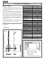 4
4
-
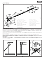 5
5
-
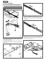 6
6
-
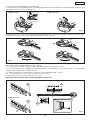 7
7
-
 8
8
-
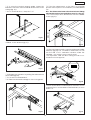 9
9
-
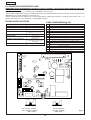 10
10
-
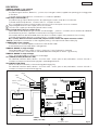 11
11
-
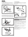 12
12
-
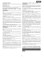 13
13
-
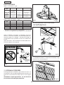 14
14
-
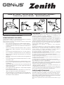 15
15
-
 16
16
-
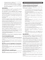 17
17
-
 18
18
-
 19
19
-
 20
20


en otros idiomas
- français: Genius Zenith Mode d'emploi
- italiano: Genius Zenith Istruzioni per l'uso
- English: Genius Zenith Operating instructions
- Deutsch: Genius Zenith Bedienungsanleitung
Artículos relacionados
-
Genius JA668 Instrucciones de operación
-
Genius Zenith Instrucciones de operación
-
-
-
-
-
-
-
-
Genius JA487C Instrucciones de operación