Kenmore 79040432802 Guía de instalación
- Categoría
- Hornos
- Tipo
- Guía de instalación
Este manual también es adecuado para

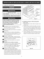
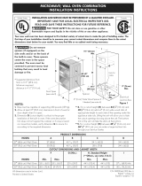
iNSTALLATiON AND SERVICE MUST BE PERFORMED BY A QUALiFiED
iNSTALLER, iMPORTANT: SAVE FOR LOCAL ELECTRICAL iNSPECTOR'S USE.
READ AND SAVE THESE iNSTRUCTiONS FOR FUTURE REFERENCE.
F_ FOR YOUR SAFETY: Do not store or use gasoline or other flammable
vapors and liquids in the vicinity of this or any other appliance.
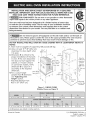
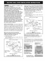
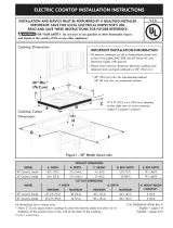
Your new wall oven has been designed to fit a limited variety of cutout sizes
to make the job of installing easier. The first step of your installation should be
to measure your current cutout dimensions and compare them to the cutout
dimensions chart below for your model. You may find little or no cabinet work
being necessary.
Canada
United States
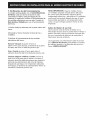
pr_ Do not remove spacers (if equipped) on the side walls and/or on the back of
the built=in oven. These spacers center the oven in the space provided. The oven must be
centered to prevent excess heat buildup that may result in heat damage or fire.
DO NOT INSTALL THIS WALL OVEN IN A BASE CABINET WITH A COUNTERTOP ABOVE IT.
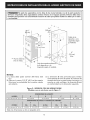
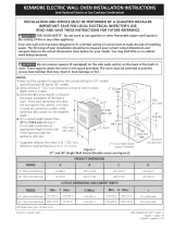
NOTES:
1. Base must be capable of supporting 150 pounds (68 kg).
2. Allow at least 19 3/8" (49.2 cm)
23_/8'' z
clearance for door depth when (5 cm)
it is open.
3. Dimension G is critical to the )_"_c
proper installation of the built- t_.
in oven. If the oven decorative
/
trim does not butt against the
cabinet, or if noise is heard B
on convection models, verify
dimension G to assure it is /
according to the required
dimension. Doo_6pe,
4. For a cutout height (see.note 2)
greater than H dimension .............
see "Adjusting oven ........
height" section.
Required distance from _.
floor is 31" (78.7 cm).
I
11/2"
(3.8 cr
Hole for
cable and
electrical
junction
box on
/_ght side
3" (7.6 cm)
Max.
Junction Box
Location
Figure 1 = SINGLE OVENS
(Double Ovens see Figure 2)
24" (61 cm) Wall Oven 22 (55.9) 221/2 (57.2)
All dimensions are stated in inches and cm.
23V2 (59.7) 27 5/8 (70.2) 28 (71.1) 24 (61) Min
Printed in Canada
P/N 318206003 (1109) Rev. A
English - pages 1-8
Espa_ol - p6ginas 9-16

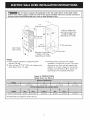
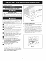
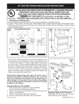
Do not remove spacers (if equipped) on the side wails and/or an the back of the
built-in oven. These spacers center the oven in the space provided. The oven must be centered to
prevent excess heat buildup that may result in heat damage or fire.
!
L
Door Open
(see note 2)
11/, ,w
23_/4 ,, /2 __
S,:n (3.8 cm) Mi n. <-___
/ .
;: _ !120o2 ¢m)min,
4813/16 (124im) max" i _
111/2"f_
Electrical Juncitio_Bol _11"_-(5"1
(Right or left side v
depending on model)
Hole for cable and
electrical junction box
on left or right side
jdepending on model.
_3" (7.6 cm) Max.
cm) Max.
NOTES
I. Base must be capable of supporting 300
pounds (136 kg).
2. Allow at least 19 3/8" (49.2 cm) clearance for
door depth when it is open.
3. Dimension G is critical to the proper
installation of the built-in oven. if the oven
decorative trim does not butt against the
cabinet, or if noise is heard on convection
models, verify dimension G to assure it is
according to the required dimension.
Figure 2= DOUBLE OVENS
(Single Ovens see Figure 1)
25 V2 (64.8)
24" (61 cm) Wall Oven 22 (55.9) 221/2 (57.2)
All dimensions are stated in inches and cm.
23V2(59.7) 48 (121.9) 49 (124.5) 24 (61) Min

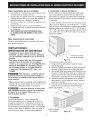
important Notes to the installer
1. Read att instructions contained in these
installation instructions before installing the wall
oven.
2. Remove all packing material from the oven
compartments before connecting the electrical
supply to the watt oven.
3. Observe all governing codes and ordinances.
4. Be sure to leave these instructions with the
consumer.
5. Oven door may be removed to facilitate
installation.
6. THESE OVENS ARE NOT APPROVED FOP,
STACKABLE OR SIDE-BY-SIDE INSTALLATION.
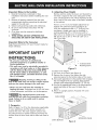
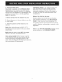
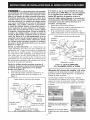
2. Adjusting Oven Height
Remove and lay aside the lower vent decorative
trim that is taped to the outer side panel of the
oven. The decorative trim will be fastened to the
lower front of the oven after it has been installed
in the cabinet.
There is a 13¼" (4.4 cm) height adjustment on
models with extension panel (see figure 3).
With this adjustment and a 1/4" (0.6 cm) trim
overhang, a single oven can be installed in
existing openings 27s/8 '' (70.2 cm) to 29s/8 ''
(75.2 cm) or a double oven in existing openings
48" (121.9 cm) to 50" or 49 7/8" (127 cm or
126.7 cm) high.
important Note to the Consumer
Keep these instructions with your Owner's Guide for
future reference.
iMPORTANT SAFETY
iNSTRUCTiONS
* Be sure your wall oven is installed and
grounded properly by a qualified installer or
service technician.
* This wall oven must be electrically grounded in
accordance with local codes or, in their absence,
with the Natlonal Electrlcal Code ANSI/NFPA
No.70- latest edition in United States, or with
CSA Standard C22.1, Canadian Electrlcal Code,
Part 1, in Canada.
Stepping, leaning or sitting an the
door of this wall oven can result in serious injuries
and can also cause damage to the wall oven.
* Never use your wall oven far warming or
heating the room. Prolonged use of the walt oven
without adequate ventilation can be dangerous.
The electrlcal power to the oven
must be shut off while llne connections are being
made. Failure to do so could result in serious
injury or death.
To
1.
2.
.
.
.
stmentHoles
_"_'_ _iiii_ Extension
Panel
Mounting Screws
Figure 3
adjust oven height:
Lay oven on its back (see figure 4).
Remove the 6 screws that fasten the side
extension panel to the bottom sides of the oven.
Move each panel down to the position that increases
the oven height to fit your opening. Each position
changes oven height approximately 1/2" (1.3cm).
Line up the appropriate holes in the side extension
panels and sides of the oven. Put back the 6
screws.
Return to upright position. Proceed with oven
installation.
OVEN DOOR
|. Carpentry
Refer to figure 1 or 2 for the dimensions applicable
to your appliance, and the space necessary to
receive the oven. The oven support surface may
be solid plywood or similar material, however the
surface must be level from side to side and front to
rear.
3
OVEN BOTTOM'
Figure 4
EXTENSION PANEL

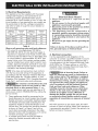
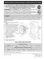
3. Electrical Requirements
This appliance must be supplied with the proper
voltage and frequency, and connected to an
individual, properly grounded branch circuit,
protected by a circuit breaker or fuse. To know the
circuit breaker or fuse required by your model, see
the serial plate to find the wattage consumption
and refer to table A to get the circuit breaker or
fuse amperage.
| I
Appliance ProtectiQn Appliance ProtectiQn
Rating Watts Circuit Rating Watts Circuit
n H
240V Recommended 208V Recommended
Lessthan 4800W 20A Lessthan 4100W 20A
4800W - 7200W 30A 4100W - 6200W 30A
7200W - 9600W 40A 6200W - 8300W 40A
9600W and + 50A 8300W and + 50A
Table A
Observe all governing codes and local ordinances
1. A 3-wire or 4-wire single phase 120/240 or
120/208 Volt, 60 Hz AC only electrical supply is
required on a separate circuit fused on both sides
of the line (red and black wires). A time-delay fuse
or circuit breaker is recommended. DO NOT fuse
neutral (white wire). Onty certain cooktop models
may be installed over certain built-in electric oven
models. Approved cooktops and built-in ovens are
listed by the MFG ID number (see the insert sheet
included in the literature package).
NOTE: Wire sizes and connections must conform
with the fuse size and rating of the appliance in
accordance with the American National Electrical
Code ANSI/NFPA No. 70-latest edition, or with
Canadian CSA Standard C22.1, Canadian Electrical
Code, Part 1, and local codes and ordinances.
An extension cord should not be used
with this appllance. Such use may result in a fire,
electrlcal shock, or other personal injury, if you
need a longer power cord you can purchase a 10'
(3 m) power cord kit #903056-9010 by calling the
Service Center.
2. These appliances should be connected to the
fused disconnect (or circuit breaker) box through
flexible armored or nonmetallic sheathed cable.
The flexible armored cable extending from the
appliance shoutd be connected directly to the
junction box. The junction box should be located
as shown in Figure 1 or Figure 2 and with as
much slack as possible remaining in the cable
between the box and the appliance, so it can be
moved if servicing is ever necessary.
3. A suitable strain relief must be provided to
attach the flexible armored cable to the
junction box.
Electrical Shock Hazard
* Electrlcal ground is required on this
appliance.
* Do not connect to the electrlcal supply until
appffance is permanenHv grounded.
* Disconnect power to the junction box before
making the electrlcal connection.
* This appliance must be connected to a
grounded, metallic, permanent wiring system,
or a grounding connector should be connected
to the grounding terminal or wire lead on the
appffance.
* Do not use a gas supply llne for grounding the
appffance.
Failure to do any of the above could result in a
fire, personal injury or electrical shock.
4. Electrical connection
It is the responsibility and obligation of the
consumer to contact a qualified installer to assure
that the electrical installation is adequate and is
in conformance with the National Electrical Code
ANSI/NFPA No. 70-latest edition, or with CSA
Standard C22.1, Canadian Electrical Code, Part 1,
and local codes and ordinances.
Risk of electrical shock (Failure to
heed this warning may result in electrocution or
other serious injury.) This appllance is equipped
with copper lead wire. if connection is made to
aluminum house wiring, use only connectors that
are approved for joining copper and aluminum
wire in accordance with the National Electrical
Code and local code and ordinances. When
installing connectors having screws which bear
direcHy on the steel and/or alumlnum fiexlble
conduit, do no tighten screws sufflcientiy to
damage the flexible conduit. Do not over bend
or excessively distort fiexlble conduit to avoid
separation of convolutions en exposure of internal
wires.
DO NOT ground to a gas supply pipe. DO NOT
connect to electrical power supply until appliance
is permanently grounded. Connect the ground wire
before turning on the power.
4

(If your appliance is equipped with a
white neutral conductor.)
This appliance is manufactured with a white
neutral power supply and a frame connected
copper wire. The frame is grounded by connection
of grounding lead to neutral lead at the
termination of the conduit, if used in USA, in a
new branch circuit installation (1996 NEC), mobile
home, recreational vehicles, where local code do
not permit grounding trough the neutral (white)
wire or in Canada, disconnect the white and
green lead from each other and use ground lead
to ground unit in accordance with local codes,
connect neutral lead to branch circult-neutral
conductor in usual manner see Figure 6. If your
appliance is to be connected to a 3 wire grounded
junction box (US only), where local code permit
connecting the appllance-grounding conductor to
the neutral (white) see Figure 5.
NOTE TO ELECTRICIAN: The armored cable leads
supplied with the appliance are UL-recognized for
connection to larger gauge household wiring. The
insulation of the leads is rated at temperatures much
higher than temperature rating of household wiring.
The current carrying capacity of the conductor is
governed by the temperature rating of the insulation
around the wire, rather than the wire gauge alone.
Where local codes permit connecting the
appffance-groundlng conductor to the neutral
(white) wire (US Only) (see figure 5):
1. Disconnect the power supply.
2. In the junction box:
connect appliance and power supply cable wires
as shown in Figure 5.
Cable from Power Supply
White Wire -'_-_
(Neutral) _ :::::............
Red _.
Wires I" _--_!//k_
Ground Wire /
(Bare or Green _
Wire)
Black
ires
Junction
Box
i ...J _iVhite Wire
(Neutral)
U.L.-Listed Conduit
Connector (or CSA listed)
Cable from appliance
Figure 5
3-WIRE GROUNDED JUNCTION BOX
ff oven is used in a new branch circuit installation
(1996 NEC), mobile home, recreational vehicle,
or where local codes DO NOT permit grounding
through the neutral (white) wire, the appliance
frame MUST NOT be connected to the neutral wire
of the 4-wire electrical system. (see figure 6):
1. Disconnect the power supply.
2. Separate the green (or bare copper) and white
appliance cable wires.
3. In the junction box:
connect appliance and power supply cable wires
as shown in Figure 6.
Cable from Power Supply
Ground Wirex _-_
Red __
Ground Wire "_
(Bare or _Lk_
Green Wire) __
Junction
Box
_?j_'_/- White Wire
_ Black
::U.k.-kisted Conduit
Connector (or CSA listed)
Cable from appliance
Figure 6
4-WIRE GROUNDED JUNCTION BOX
Model and Serial Number Location
The serial plate is located along the interior side
trim of the oven and visible when the door is
opened.
When ordering parts for or making inquires about
your oven, always be sure to include the model and
serial numbers and a lot number or letter from the
serial plate on your oven.
Single Wall Oven
Serial Plate Location
Double Wall Oven
Serial Plate Location
5

5. Cabinet installation
Heavy Weight Hazard
* Use 2 or more people to move and install wall
oven.
* Failure to follow this instruction can result in
injury or damage to the unit.
The wall oven can tip when the door is open. The
antl-tlp mounting screws supplied with the wall
oven must be installed to prevent tipping of the
wall oven and injury to persons.
_Unpack the wall oven. Remove the bottom trim
taped on the oven side panel.
HFind the 2 anti-tip mounting screws included in
the literature package.
_ Insert the oven into the cabinet opening. Slide
oven inward leaving 11/2'' (3.8 cm) clearance
between the oven and front of cabinet.
_Putt the armored cable through the hole for it in
the cabinet and toward the junction box while
moving the appliance inward.
_Push the oven in and against the cabinet.
install the Anti-tip Mounting Screws
A. The mounting hotes in the side trims may be
used as a temptate to locate the appliance
mounting screw holes (see figure 7).
B. Use the two screws supplied to fix the
appliance to the cabinet.
_ Jnstaff the Bottom Trim
Place the top of the bottom trim over the side
trim tabs on each side of the oven below the
oven door and fix it using the 2 screws supplied
in the mounting holes located on each side trim
below the oven frame (see Figure 7).
Mounting
Decorative
Trim
Mounting
Figure 7
6. Leveling the Wall Oven
1. Instalt an oven rack in the center of the upper
oven (see Figure 8).
2. Place a level on the rack. Take 2 readings with
the level placed diagonally in one direction
and then the other. Use wood shims under the
walt oven to level if necessary.
3. Repeat in the lower oven if you have a double
cavity watt oven. If the level indicates that the
rack is not level, use wood shims to reach a
compromise for both ovens.
Figure 8
6

Z Checking Operation
Your model is equipped with an Electronlc Oven
Control. Each of the functions has been factory
checked before shipping. However, it is suggested
that you verify the operation of the electronic oven
controls once more. Refer to the Use and Care
Guide for operation.
1. Remove alt items from the inside of the oven.
2. Turn on the power to the oven (refer to your Use
& Care Guide).
3. Verify the operation of the electronic oven
controls:
Bake-After setting the oven to 350°F/177°C
for baking, the lower element in the oven should
become red.
BrolI-When the oven is set to BROIL, the upper
element in the oven should become red.
iMPORTANT NOTE: A fan inside the upper rear
part above the oven (some models) provides
additional cooling of the oven electrical and
electronic components. The fan will continue to
run after the oven has been operating at high
temperatures.
Before You Call for Service
Read the Before You Call for Service Checklist
and operating instructions in your Use and Care
Guide. It may save you time and expense. The
list includes common occurrences that are not the
result of defective workmanship or materials in this
appliance.
Refer to your Use and Care Guide for Sears service
phone numbers, or call 1-800-4-MY-HOME ®.
Clean (same madels)-When the oven is set for
a self-cleaning cycle, the upper element should
become red during the preheat portion of the
cycle. After reaching the self-cleaning temperature,
the lower element will become red.
7

Notes
8

LA iNSTALACION Y EL SERViCIO DEBEN SER EFECTUADOS POR UN Canad_
iNSTALADOR CALiFICADO. IMPORTANTE: GUARDE ESTAS INSTRUCCIONES
PARA USO DEL iNSPECTOR LOCAL DE ELECTRICIDAD. LEA Y GUARDE
ESTAS INSTRUCCiONES PARA REFERENCIA FUTURA.
PARA SU SEGURIDAD: No aJmanece nl utilice gasollna u otros vapores y Estados Unidos
liquidos inflamabJes en la proximldad de este o de cualquler otto artefacto.
El primer paso para su instalaci6n debe de ser el de medlr las dimenslones de la apertura
y compararlas con las que se indlcan en el cuadro de dlmenslones del hueco de la figura
1. Poslbiemente encontrar_ que algOn trabajo de carpinter[a ser_ necesarlo.
No quite los separadores (si los hay) de los muros laterales o/y de la parte posterior del homo
emportado. Estosespacladores centran el homo en el espaclo provisto. El homo debe estar centrado para
_revenir una concentraci6n excesiva de calor que podria resultar en da6os pot el calor o un incendlo.
NO INSTALE ESTE HORNO 24" EN LA PARTE DE ABAJO DE UN ARMARIO DE COCINA QUE TIENE UN
MOSTRADOR ENCIMAo
NOTAS
1. La basa debe poder sostener 150 libras
231/8"
(68 kg.) (ss.zom)
2. Deie par Io menos 19 3/8" (49.2 cm)
de espacio tibre para la profundidad _.
de la puerta cuando esta abierta.
3. La dimensi6n G est6 primordial
para instalar correctamente et B
horno de pared. Si el adorno del
armaz6n det horno no topa contra
el armario, o si escuche un ruido,
verifique si la dimensi6n G _._\
est6 en conformidad con la ,-................._
Puerta Ablerta _t!
dimensi6n reauerida ' _ _ J
7 . " (vea lan eta 2) _._%_,_'T_ ._
4. tara un recorTaao con ....... ....._jJ- . a" J
altura de m6s de H ............."
dimensi6n vea "Ajustando
la Altura del Homo" A
secci6n. \_
'* Distancia necesario desde
el suelo es 31" (78.7 cm).
11/2 t_
(78.731cm).... _ _ "'iJ'"(_ "" _
L _ _"_'_,_ " _ Max3_"(7"6cm)
Caja de
Agujero a
la derecha
para el cable
y la caja de
empalme
el_ctrica.
/
Figura 1- MODELOS CON UN SOLO HORNO
(Modelos de homo doble yea la Figura 2)
Homo de pared 24" (61 cm) 23 7/8 (60.6) 31 7/16 (79.9) 21_¼ (55.2) 25 3/16 (64)
Homo de pared 24" (61 cm) 22 (55.9) 221/_ (57.2)
Todas las dimensiones se dan en putgadas (cm).
23V2 (59.7) 27 5/8 (70.2) 28 (71.1) 24 (61) Min
Imprimido en Canada
P/N 318206003 (1109) Rev. A
English - pages 1-8
EspaBoi - p6ginas 9-16

Fr__l No quite los separadores (sl los hay) de los muros laterales o/¥ de la parte posterior
del homo emportadoo Estos espacladores centran el homo en el espacio provisto. El homo debe estar
centrado para prevenir una concentraci6n exceslva de calor que podria resultar en da_os por el calor
o un incendlo.
°
_ Puerta Abierta
(vea la nora)
231/4"
(29.2 c_)
Caja de empalme el6ctricc
(a la derecha o a ta
izquierda segOn el modelo).
Cable (a la
derecha o a la
izquierda segOn
et modelo).
,,
cm)
Max.
NOTAS:
1. La basa debe poder sostener 300 libras (136
kg.)
2. Deje por lo menos 19 3/8" (49.2 cm) de espacio
libre para ta profundidad de la puerta cuando
esta abierta.
3. La dimensi6n G est6 primordial para instalar
correctamente el horno de pared. Si el adorno del
armaz6n del horno no topa contra el armario, o si
escuche un ruido, verifique si la dimensi6n G est6
en conformidad con la dimensi6n requerida.
Figura 2 - MODELOS CON UN HOP, NO DOBLE
(Modelos con un solo homo yea la Figure 1)
Homo de pared 24" (61 cm) 22 (55.9) 221/2 (57.2)
Todas las dimensiones se dan en putgadas (cm).
23V2 (59.7) 48 (121.9) 49 (124.5) 24 (61) Min
10

Notas importantes para el instalador
1. Lea todas tas instrucciones contenidas en este
manual antes de instalar el horno.
2. Saque todo el material usado en et embalaje del
comparfimiento det horno antes de conectar el
suministro el6ctrico o de gas a la estufa.
3. Observe todos los c6digos y regtamentos
perfinentes.
4. Deje estas instrucciones con el consumidor.
5. La puerta del horno se puede quitar para facilitar
la instalaci6n.
6. ESTE HORNO NO ESTA APROBADO PARA
LA INSTALACI6N DE RIMERO O DA LADO A
LADO.
2. Ajustando la Altura del Homo
Retire y deje a un lado la rejitla que est6 sujeta
con cinta adhesiva al panel exterior del horno.
Esta rejilla se sujetar6 a la parte baja frontal del
homo, despu6s de que este se haya instalado en
el armario.
En estos modelos hay 13¼'' (4.5 cm) de ajuste en la
altura (vea ta figura 3). Con este ajuste y 1/4" (0.6
cm) del borde que sobresale, el electrodomestico
puede instalarse en huecos de 27s/8 '' (70.2 cm) a
29s/8 '' (75.4 cm) (para homo sencillo) o de 48" (121.9
cm) a 50" (127 cm) o 49 7/8" (126.7 cm) de alto
(para homo dobte).
Nora importante al consumidor
Conserve estas instrucciones y el manual del usuario
para referencia futura.
INSTRUCCIONES
IMPORTANTES DE SEGURIDAD
• Aseg_rese de que su homo a pored sea
instalada ¥ puesta a tlerra de farina aproplada
par un instaladar callflcada a par un t_cnica de
servicia.
• Este homo de pored debe ser el_ctrlcamente
puesta a tlerra de acuerda con los c6dlgos
locales a, en su ausencla, con el C6dlgo El_ctrica
Nacianal ANSI/NFPA No. 70-_ltlrna edici6n
en los Estadas Unldas, o el C6dlgo El_ctrica
Canadlense CSA Standard C22.1, Port 1, en
Canada.
Pisar, apoyarse, a sentarse sabre la
puerto de este homo a pored puede resultar en
serlas leslones ¥ tambi_n puede causar da_as al
homo a pored.
• Nunca use su harna a pored para calentar el
cuarto. Et usa prolongado de la estufa sin la
ventilaci6n adecuada puede ser peligroso.
La corrlente el_ctrlca al homo debe
estar apagada rnientras se hacen las conexiones
de ffneas. Si no se apaga, da_as serlas a la
muerte padrian resultar.
1. Carpinteria
Consutte las Figuras 1 y 2 para conocer las
dimensiones pertinentes al modelo de su homo y
al espacio necesario en el que poner el horno. La
superficie donde se va a apoyar el homo debe de
ser de madera contrachapada s6tida u otro material
similar y, sabre todo, la superficie tiene que estar a
nivel, de lado a lado, y de atr6s hacia adelante.
Agujeros de ajuste
jz
`%
`% `% Tornillos de montaje
_. `%4..........para al de extensi6n
,%
Figura 3
Para ajustar la altura del homo:
1. Ponga el horno apoyado en la parte trasera.
(vea ta figura 4)
2. Quite los 6 tornillos que sujetan el panel de extensi6n
lateral a ta parte inferior de los lados det horno.
3. Mueva cada panel hacia abajo, hasta la posici6n que
aumenta la aitura de! homo para que se adapte a la
apertura que usted tiene. Cada posici6n cambia la affu-
ra del homo 1/2 pulgada (1.3cm) aproximadamente.
4. Alinee los agujeros apropiados en los paneles
de extensi6n yen los lados del homo. Vuelva a
poner los 6 tornillos.
5. Proceda con la instalaci6n del homo. Vuelva a
poner el horno en posici6n vertical posici6n.
PUERTADELHORNO
PARTEDEABAJO
DEL HORNO Figura 4
PANELDE
EXTENSION
11

3. Requerirnientos El_ctricos
Se debe proveer el voltaje y ta frecuencia apropiados
a este electrodom6stico, y conectarse a un circuito
individual correctamente puesto a tierra, protegido por
un interruptor o un fusible. Para conocer el interruptor
o fusible que requiere su modelo, vea la ptaca serial
para encontrar ta consumaci6n del vatiaje y refierase
al cuadro A para encontrar el amperaje del interruptor
o fusible.
Grados de Se reCOm!enda , Grados d _ Se rec0m!end a
Vati0S del una pr0tecc!6 n I Vat i0s d e! una pr°tecc!6n
electrodom_sfico al ckcuito electrodarn_stico a! circui_o
240v 208v I
Menos de 4800W 20A Menos de 4100W 20A
4800W - 7200W 30A 4100W - 6200W 30A
7200W - 9600W 40A 6200W - 8300W 40A
9600W and + 50A 8300W and + 50A
Table A
Observe todos los c6dlgos que goblernan y ordenanzas
locales
1. Un cable de 3 o 4 alambres monof6sico 120/240
o 120/208 vottios, 60 hertzios es ta 6nica fuente
el6ctrica que requiere en un circuito separado en
ambos lados de la t_nea (atambre negro y alambre
rojo) (se recomienda un fusible o un interruptor
de retraso de tiempo). No funda a cable neutro
(alambre blanco). Se debe de tener precauci6n al
combinar un homo de pared y una cubierta, refl6rase
a la placa de seria de cada uno de los aparatos.
NOTA: Los tamafios y tas conexiones del alambre
deben conformarse con el tamafio del fusible y el
grado de la apticaci6n de acuerdo con el c6digo
El6ctrico Nacional Americano ANSI/NFPA No. 70-
uttima edici6n, o con el est6ndar CSA canadiense
C22.1, c6digo et6ctrico canadiense, parte 1,y c6digos
y ordenanzas locales.
No se debera usar extenslones
para enchufar este electrodom_stlco. Esto podria
causar un incendio, choque el_ctrico u otto tlpo
de da_o personal Si usted necesita un cable mas
largo, puede ordernar un cable de 10" kit 903056-
9010 ltamando al centro de Servicio.
2. Este electrodom6stico debe conectarse a ta caja
de fusibtes (o de cortocircuito), por medio de un
cable btindado flexible o un cabte con forro no
met61ico. El cable btindado flexibte que va desde
el electrodom6stico debe de estar conectado
directamente a la caja de empalme. La caja
de empalme debe de estar localizada en el
lugar que se indica en la Figura 1 o 2, dejando
tanto exceso de cable como sea posibte entre ta
caja y el electrodom6stico, de forma que as_el
electrodom6stico se pueda mover f6citmente, si
fuera necesario para hacer una reparaci6n.
3. Se debe de usar un conector que reduzca ta
tirantez de una forma adecuada para unir el
cable blindado flexible a la caja de empalme.
Riesgo de choque el_ctrlco
* Una puesta a tierra se requlere en este
aparato.
* No Io conecte a la corrlente el_ctrica hasta
que el aparato haya sido puesto a tlerra.
* Desconecte la corrlente el_ctrlca a la caja de
empaffnes antes de hacer la conexi6n el_ctrlca.
* Este aparato debe estar conectado con un
slstema de alambres puesto en tlerra, met6ffco
y perrnanente o un conector de puesta a tlerra
debe conectarse al termlnal de puesta a tierra
o el alambre conductor en al aparato.
* No utiffce el sumlnistro de gas para hater la
puesta a tlerra.
La faffa de cualquiera de las instrucciones
mencionadas podria resuffar en un incendio,
choque el_ctrlco o leslones personales.
4. Conexi6n el ctrica
El usuario tiene la responsabitidad personal y
obligaci6n de utitizar un instatador catificado,
para asegurar que la instalaci6n el6ctrica est6
hacha de forma adecuada y est6 conforme con el
C6digo El6ctrico Nacional ANSI/NFPA No. 70-
Ottima edici6n en los Estados Unidos, o el C6digo
El6ctrico Canadiense CSA Standard C22.1, Part 1,
en Canad6.
Riesgo de choque el_ctrico (El no
prestar atenci6n a esta advertencla puede resuffar
en electrocuci6n u otras leslones graves.) Este
electrodom_stlco est6 equlpado con alambre de
cobre. Si se va a conectar con cableado de aluminlo
del hogar, ufiffzar Onlcamente conectores que est6n
aprobados para unit cobre y aluminlo de acuerdo
al C6dlgo Naclonal El_ctrlco (NEC por sus slglas en
ingles) y leyes y c6dlgos locales. AI instalar conectores
con torniHos que empujen directamente contra el
acero y/o alumlnio del conducto flexible, no apretar
los torniffos suficlentemente que da_en el conducto
flexible. No doblar de m6s o deformar el conducto
flexlble para evitar separar el espiral y descubrlr los
alambres infernos.
NO conecte el alambre puesto a tierra a una tuber_a
de suministro de gas. NO conecte el suministro de
energ_a el6ctrica hasta que el electrodom6stico haya
sido permanentemente puesto a tierra. Conecte et
alambre de puesto a tierra antes de enchufar por
primera vez el electrodom6stico.
12

(Si su electrodom_stlco est6 equipado
con un conductor neutro blanco.) Esteelectrodom_sfico
est6 fabricado con un sumlnistro el_ctrlco neutro
blanco y un alambre de cobre conectado al armaz6n.
El armaz6n esta puesto a fierra por un enlace de la
conexi6n a fierra con la conexi6n del neutro al final
de la linea el_ctrica, sl es usado en los estados unidos
una nueva instalaci6n de clrcuito de bifurcaci6n
(1996 NEC), casa rodante, vehiculos recreacionales,
o donde los c6digos locales no permltan poner a
tierra medlante el neutro (blanco) o en Canad6,
desconectar la conexi6n blanca de la verde V ufilizar
la conexi6n a tierra para poner a fierra la unidad de
acuerdo a los c6dlgos locales, conectar el neutro al
circulto de bifurcaci6n- conductor neutro de manera
usual Ver Figura 6. Si su electrodorn_stlco va a ser
conectado a una caja de conexi6n puesta a tierra de
3 cables (en los estados unidos solamente), donde
los c6digos locales permltan conectar el conductor
de poner a tlerra-electrodom_stlco con el neutro
(blanco) ver Figura 5.
NOTA AL ELECTRICISTA: Los conductores de
cable btindados provJstos con este artefacto son
aprobados por UL para la conexi6n at alambrado
de casa de un catibre mayor. El aistamiento de
los conductores est6 calificado para temperaturas
m6s altas que las det alambrado de la casa.
La capacidad de corriente det conductor est6
gobernada por la calificaci6n de la temperatura
del aislamiento alrededor del alambre en vez de
solamente el calibre del alambre.
Donde los c6digos locales permltan conectar el
conductor de puesta a tierra del electrodom_stico
al neutral (blanco) (Solamente en los Estados
Unidos) (yea figura 5):
1. Desconecte el suministro el6ctrico.
2. En el caja de juntas: conectar el aparato y los
cables residenciales como se muestra en la
figura 5.
Cable desde el suministro de energia
Atambre Alambre
desnudo negros
Atambre _--.
roJos
de
empalmes
desnudo
Atambre verde
Conductor de uni6n
o desnudo _..... tistado-UL (o CSA)
Cable de la estufa
Figura 5 - CAJA DE EMPALMES
DE 3 ALAMBRES PUESTA A TiERRA
Si el homo se usa en una instalaci6n de circuito
de ramal nuevo (1996 NEC), en una casa rodante,
en un vehiculo para recreaci6n o si los c6digos
locales NO permiten la conexi6n a tierra a
trav_s del cable neutral (blanco), el armaz6n del
electrodom_stlco NO TIENE QUE estar conectado
al alambre neutro del slstema el_ctrlco de 4
alambres. (ver figura 6):
1. Desconecte el suministro el6ctrico
2. Separe el atambre verde (o cobre desnudo) y el
alambre blanco del electrodom6sfico.
3. En el caja de juntas: conectar el aparato y los
cables residenciales como se muestra en la figura 6.
Cable desde el suministro de energia
Atambre
Atambre blanco
Atambre
ojos
Atambre
verde o
desnudo
Caja de
empalmes
Alambre
negros
,Atambre blanco
de uni6n
tistado-UL (o CSA)
Cable de la estufa
Figura 6- CAJA DE EMPALMES
DE 4 ALAMBRES PUESTA A TIERRA
Ubicaci6n del n0mero de modelo ¥ de serie
La placa con el n0mero de serie est6 ubicada en la
guarnici6n interior lateral del homo y se puede ver
cuando se abre la puerta.
Cuando haga pedidos de repuestos o soticite
informaci6n con respecto a su horno, est6 siempre
seguro de inctuir el n0mero de modeto y de serie y
el n0mero o letra del lore de la placa de serie de
su horno.
]3
Modelos con un solo homo- la
placa de serle est6 ublcada
aqu_.
Modelos con un homo doble=
la placa de serle est6 ublcada
aqui.

5o Instalaci6n del Gabinete
Pellcjro de Peso Pesado
* Use :2 personas o m_s para mover e instalar el
homo de pared.
* Si no cumple con esta instrucci6n, puede resultar en
lesiones personales o da_os al homo de pared
El homo de pared puede incllnarse cuando la
puerta esta ablerta. Los soportes de montaje
que vlenen con el homo de pared deben de
estar ajustadas al armario y al aparato para
evltar que el homo de pared se incline y
ocaslone quemaduras graves.
M Desembatar et horno de pared. Extraer la
guarnici6n inferior y los 2 tornitlos unidos con
cinta al panel lateral del horno.
_ Buscar los torniltos que se incluyen en el paquete
de literatura.
_ Insertar el horno en la abertura del gabinete.
Deslizar el horno hacia dentro dejando 11/2" (3,8
cm) de espacio libre entre el horno y la parte
delantera del gabinete.
Empujar el cable btindado a trav6s del orificio
del gabinete y hacia la caja de paso mientras se
desliza el accesorio hacia adentro.
El Empujar el homo hacia adentro y en contra del
gabinete.
Instalaci6n de los tornillos de montado
A. Los barrenos en las molduras laterales pueden
ser usadas como guia para localizar los
tornillos de montado de la unidad (Figura 7).
B. Use los dos tornillos proporcionados para
cotocar la unidad en la cabina.
Instalaci6n de la Guarnici6n Inferior:
Colocar la parte superior de la guarnici6n inferior
sobre las lengiJetas laterales del horno, debajo de
la puerta del homo, y fijartas usando los 2 tornillos
provistos con los orificios de montaje ubicados a
cada lado del marco del horno (ver la Figura 7).
Tornillos de
montadura
Parrilla
respiradora
Tornillos de
montadura
Ficjura 7
6o Aseg0rese de que el homo de pared
est6 a nivel
1. instale una rejilla al centro del horno superior (vea
la Figura 8).
2. Ponga un nivel por encima de la rejilla. Lea 2 veces,
una vez con el nivel a la posici6n de tado a lado, y
otra vez de atr6s hacia adelante. Utilice trozo de
madera o cuhas por debajo del horno de pared
para nivelar, si sea necesario.
3. Vuelve a empezar en el homo inferior. Si el nivel
muestra que la rejilla no esta a nivel, utilice trozo de
madera o cuhas para componer ambos hornos.
Figura 8
14

7. Verificaci6n de del funcionamiento
Su modelo est6 equipado con un Control Electr6nico
de Horno. Cada una de las funciones ha sido
controlada en f6brica antes del despacho. Sin
embargo, le sugerimos verificar el funcionamiento de
los controles electr6nicos una vez m6s. Consulte la
Guia de Uso y Cuidado para ver el funcionamiento
del horno.
NOTA IMPORTANTE: Atgunos modetos tienen
un ventitador peque_o situado dentro del panel
de control para enfriamiento adicional de los
componentes el6ctricos y electr6nicos. El ventilador
continuar6 funcionando despu6s de que el horno
haya estado operando a una temperatura alta,
como a ta que se ltega cuando el horno se est6
limpiando.
1. Extraer todos los elementos de la parte interior del
horno.
2.Encender el horno (Consular la Gufa de Uso y
Cuidado.)
3.Verificar el funcionamiento de los controles
electr6nicos del homo:
Hornear- Despu_s de poner el horno a
350°F/177°C para hornear, el elemento de la parte
de abajo del horno se debe de ponerse rojo.
Antes de llamar al servicio
Lea la secci6n Lista de Antes de ltamar en su
Manual del Usuario. Esto le podr6 ahorrar fiempo y
gastos. Esta tista incluye ocurrencias comunes que
no son el resuttado de defectos de materiales o
fabricaci6n de este artefacto.
Lea la garanfia y la informaci6n sobre el servicio
en su Manual del Usuarlo para obtener el n0mero
de tel6fono gratuito y la direcci6n del servicio o
llama 1-888-SU-HOGAR sM.
Asar- Cuando se pone et horno para asar, et
elemento de arriba del horno debe de ponerse rojo.
Limpieza (algunos rnodelos)- Cuando el horno se
pone en el ciclo para que se limpia a si mismo, el
elemento de arriba debe de ponerse rojo durante la
parte de pre-calentamiento del ciclo de limpieza.
Despu6s de que llegue a la temperatura adecuada
de limpieza, el elemento de calentamiento inferior se
encender6 y debe de ponerse rojo.
15

Notas
16
-
 1
1
-
 2
2
-
 3
3
-
 4
4
-
 5
5
-
 6
6
-
 7
7
-
 8
8
-
 9
9
-
 10
10
-
 11
11
-
 12
12
-
 13
13
-
 14
14
-
 15
15
-
 16
16


Kenmore 79040432802 Guía de instalación
- Categoría
- Hornos
- Tipo
- Guía de instalación
- Este manual también es adecuado para
en otros idiomas
Artículos relacionados
-
Kenmore 79040253413 Guía de instalación
-
Kenmore 40252 Guía de instalación
-
 Kenmore Elite 79048802100 Guía de instalación
-
Kenmore 79048083000 Guía de instalación
-
Kenmore 79048173002 Guía de instalación
-
Kenmore 79040452801 Guía de instalación
-
 Kenmore Elite 79041279000 Guía de instalación
-
 Kenmore Elite 79048032801 Guía de instalación
-
Kenmore 79048763900 Guía de instalación
-
Kenmore 79049602317 Guía de instalación


Otros documentos
-
Samsung FFEW2426UB Guía de instalación
-
Frigidaire FFEW2426US Guía de instalación
-
-
Frigidaire FFEW2426UB Guía de instalación
-
 Kenmore Elite 79097512101 Guía de instalación
-
Frigidaire CFEW3025LSA Guía de instalación
-
Frigidaire FPET3085KFC Guía de instalación
-
Frigidaire FGEW3045KBA Guía de instalación
