Magnat Audio STYLUS 5000 A El manual del propietario
- Categoría
- Altavoces de la barra de sonido
- Tipo
- El manual del propietario

CABINET SUBWOOFER
SUBWOOFER POURVU D’UN BOÎTIER
AR STATUS
STYLUS 5000 A
POWERED SUBWOOFER
WICHTIGE HINWEISE ZUR INSTALLATION
GARANTIEURKUNDE
IMPORTANT NOTES FOR INSTALLATION
OWNER’S MANUAL
IMPORTANT INSTRUCTIONS D’INSTALLATION
CERTIFICAT DE GARANTIE


4
D
8
GB
12
F
16
NL
20
I
24
E
28
P
32
S
36
RUS
40
CHN
44
J
48
Abbildungen/Illustrations

Sehr geehrter Kunde,
zunächst vielen Dank dafür, dass Sie sich für ein Magnat-Produkt entschieden haben. Wir
möchten Ihnen hierzu von unserer Seite recht herzlich gratulieren.
Durch Ihre kluge Wahl sind Sie Besitzer eines Qualitätsproduktes geworden, das welt-
weite Anerkennung findet.
Bitte lesen Sie unsere folgenden Hinweise vor Inbetriebnahme Ihrer Lautsprecher genau
durch.
GENERELLES ZUM ANSCHLIESSEN IHRER MAGNAT
SATELLITENLAUTSPRECHER
Die Anschlussterminals der Satelliten-Lautsprecher befinden sich auf der Rückseite und sind
mit einem Klemmmechanismus ausgestattet, der Kabel bis zu einem Kupferquerschnitt von
1mm
2
aufnehmen kann. Zum Anschließen der Satelliten benutzen Sie bitte handelsübliche
Lautsprecherkabel mit einem Kupferquerschnitt von 2 x 0.75mm
2
oder 2 x 1mm
2
. Die
Kabel werden auf die benötigten Längen zugeschnitten, die Enden abisoliert und die
Litzenenden verdrillt um den Anschluss an die Lautsprecherklemmen zu erleichtern.
Der Verstärker bzw. der Receiver sollte grundsätzlich ausgeschaltet sein, bis alle Verbin-
dungen hergestellt sind. Achten Sie bitte beim Anschließen der Kabel unbedingt auf die pha-
senrichtige Polung, d.h. es müssen die schwarzen (-)Klemmen der Lautsprecher mit den
(-)Klemmen des Verstärkers verbunden werden und die roten (+) Klemmen der Lautsprecher
entsprechend mit den (+)Klemmen des Verstärkers. Um ein phasenrichtiges Anschließen zu
erleichtern, ist bei Lautsprecherkabeln normalerweise eine Kabelader markiert.
Überprüfen Sie noch einmal, dass die Kabel richtig fest sitzen und sich kein Kurzschluss
etwa durch abstehende Drähtchen gebildet hat. Dies wäre für den angeschlossenen Ver-
stärker sehr gefährlich.
ANSCHLUSS AN EINEN AV-RECEIVER
Den Anschluss des Systems an einen AV-Receiver verdeutlicht Bild 1 (Receiver ohne Sub-
wooferausgang) und Bild 2 (Receiver mit Niederpegel-Subwooferausgang), den Anschluss
an eine Kombination aus Vor- und Endverstärker ist in Bild 3 dargestellt.
Achtung: Im Setup des Receivers müssen die Lautsprecherkanäle Front, Center und Rear
auf ‚small’ oder ‚klein’ gestellt werden, falls Ihr Receiver diese Option bietet. Bitte beachten
Sie hierzu auch die Bedienungsanleitung des Receivers.
Center-, Front- und Rear Lautsprecher sind auf der Gehäuserückseite gekennzeichnet. Der
Centerlautsprecher wird auf oder unter das Fernsehgerät gestellt. Die Frontsatelliten wer-
den links und rechts mit möglichst gleichem Abstand zum Fernseher in Ohrhöhe platziert.
Die Rearsatelliten werden links und rechts neben oder hinter dem Hörplatz, am besten
4
D

etwas oberhalb der Ohrhöhe, aufgestellt. Die Aufstellung des Subwoofers ist im All-
gemeinen unkritisch, sollte aber möglichst in der Nähe der Frontsatelliten erfolgen.
-Die Bedienungselemente des Subwoofers im Einzelnen zeigt Bild 4
NETZANSCHLUSS
Da es sich um einen Subwoofer mit eingebautem Verstärker handelt, muß dieser über das
beiliegende Netzkabel an die Netzleitung angeschlossen werden. Der Netzspannungswahl-
schalter 6 ist ab Werk auf 230 V für die Verwendung im europäischen Raum eingestellt.
Sehr wichtig: Wird der Subwoofer in 115 V-Stellung an das 230 V Netz angeschlossen,
führt dies zwangsläufig zur Zerstörung des eingebauten Verstärkers!
POWER-SCHALTER
In der Stellung "Off" ist der Subwoofer ausgeschaltet, in der Stellung "On" eingeschal-
tet. Am besten benutzen Sie die Stellung "Auto", dann schaltet sich der Subwooofer au-
tomatisch ein, wenn er ein Musiksignal erhält. Erhält er kein Signal mehr, schaltet er sich
nach etwa einer Viertelstunde automatisch ab. Die LED (9) leuchtet im Standby-Betrieb rot
und im Betriebszustand grün. Wird das Gerät längere Zeit nicht benutzt, sollte der Netz-
stecker aus der Steckdose gezogen werden.
LINE EINGÄNGE
Zum Anschluss an Niederpegelausgänge des Receivers/Verstärkers. (Siehe Bild 2 und 3)
HOCHPEGELEINGÄNGE
Zum Anschluss an Hochpegel- (Lautsprecher-) Ausgänge des Receivers/Verstärkers. Siehe
Bild 1
PEGELREGLER
Mit diesem Regler stellen Sie die Lautstärke im Bassbereich nach Ihren Wünschen wie folgt
ein:
1. Der Bassregler an Ihrem Verstärker wird in Mittelstellung (linear) gebracht.
2.
Ganz wichtig: Den Pegelregler auf den linken Anschlag drehen (kleinste Lautstärke).
3. Legen Sie Musik auf und erhöhen Sie die Lautstärke mit dem Regler des Verstärkers
auf das gewünschte Maß.
4. Den Basspegel mit dem Pegelregler auf gewünschte Lautstärke bringen.
5
D

TRENNFREQUENZREGLER
Hiermit stellen Sie die höchste Frequenz ein, bis zu der Ihr Subwoofer arbeitet. In Kombina-
tion mit Ihren Ihren Stylus 5000 A Satelliten sollte der Regler auf 120Hz –150Hz eingestellt
werden.
SICHERUNG
Als Sicherung darf nur der Typ verwendet werden, der auf der Rückseite des Verstärkers
neben dem Sicherungshalter angegeben ist.
WICHTIGER SICHERHEITSHINWEIS
Niemals den Subwoofer Tropf- und Spritzwasser aussetzen. Ebenfalls darf der Subwoofer
nicht zum Abstellen von Vasen oder anderen mit Flüssigkeit gefüllten Behältern benutzt
werden.
TIPPS ZUR VERMEIDUNG VON REPARATURFÄLLEN
VORSICHT MIT DEM LAUTSTÄRKEREGLER !!!
Sollten Sie einen Verstärker benutzen, der eine wesentlich höhere Ausgangsleistung besitzt,
als bei den Boxen an Belastbarkeit angegeben ist, können brachiale Lautstärken zur
Zerstörung der Lautsprecher führen - was aber recht selten vorkommt.
Verstärker mit schwacher Ausgangsleistung jedoch können schon bei mittleren Lautstär-
ken den Boxen gefährlich werden, weil sie viel schneller übersteuert werden können als
kräftige Verstärker. Diese Übersteuerung verursacht deutlich messbare und hörbare
Verzerrungen, die äußerst gefährlich für Ihre Lautsprecher sind.
Bitte achten Sie deshalb bei der Lautstärkeeinstellung auf Verzerrungen - und drehen
Sie dann sofort leiser. Wer gerne laut hört, sollte darauf achten, dass der Verstärker zu-
mindest die Ausgangsleistung aufbringt, mit der die Boxen belastet werden können.
IM ALLGEMEINEN...
...können Verstärker, Tuner und CD Player, nicht nur bei preiswerten Produkten, nichthör-
bare, hochfrequente Schwingungen erzeugen. Sollten Ihre Lautsprecher bei leiser bis mitt-
lerer Lautstärke ausfallen, lassen Sie bitte Ihre Anlage vom Fachmann daraufhin überprüfen.
6
D

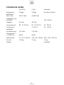
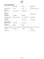
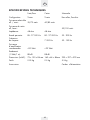
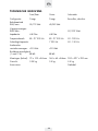
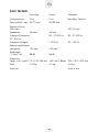
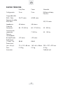
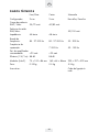
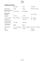
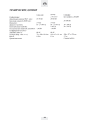
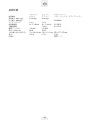
TECHNISCHE DATEN
Front/Rear Center Subwoofer
Konfiguration: 2-Wege 2-Wege Bassreflex, Downfire
Belastbarkeit
RMS / Max.:
35/70 Watt 40/80 Watt
Ausgangsleistung
RMS/Max.:
50/100Watt
Impedanz: 4-8 Ohm 4-8 Ohm
Frequenzbereich:
85 - 27 000 Hz 80 - 27 000 Hz 30 - 200 Hz
Trennfrequenz:
7 000 Hz 50 - 150 Hz
Empfohlene
Verstärkerleistung:
>20 Watt >20 Watt
Wirkungsgrad
(1 Watt/1 m): 88 dB 88 dB
Maße (BxHxT):
73 x 100 x 84 mm 160 x 65 x 84mm 200 x 327 x 320 mm
Gewicht:
0.35 kg 0.5 kg 5.5 kg
Zubehör: Netzkabel
D
7

8
GB
Dear customer,
Congratulations on your fine new loudspeakers and thank you very much for choosing
Magnat! You have made an excellent choice. The high-quality speakers produced by
Magnat are renowned all over the world.
For best results and to avoid damage please study the instructions and information below
carefully before using your new loudspeakers.
GENERAL NOTES ON CONNECTING YOUR
MAGNAT SATELLITE SPEAKERS
The connectors are located at the rear of the satellite speakers. They are equipped with
a clamping mechanism for cables cross-sections of up to 1 mm
2
. To connect the satellites,
please use normally available 2 x 0.75mm
2
or 2 x 1mm
2
loudspeaker cables. The cables
are to be cut to the required length, the ends stripped and the end of the wires twisted to
make it easier to connect them to the terminals.
Always turn off the amplifier or receiver before connecting or disconnecting loudspeaker
cables. For good sound the cables must be connected so that the speakers are “in phase”.
This means that the black negative terminals on the speakers (-) must be connected to the
negative (-) terminals on the amplifier, the positive (+) speaker terminals to the positive (+)
amplifier terminals. To make this easier one wire of most speaker cables is marked with
a coloured strip or a ridge in the insulation.
Before switching on the system double-check all your connections and make sure that the
terminal screws are tight and that there are no short circuits caused by stray wire filaments
– this could cause serious damage to your amplifier!
CONNECTION TO AN AV RECEIVER
Connection of the system to an AV receiver is shown in figure 1 (receiver without a sub-
woofer output), figure 2 (receiver with low-level subwoofer output), and figure 3 (pre-amp
and power amplifier).
Note: In the receiver set-up, the front, center, and rear loudspeaker channels should be
set to ‘small’ if your receiver supports this option. Please consult the user manual supplied
with your receiver.
Centre, front and rear speakers are identified on the rear of the cabinet. The center loud-
speaker should be positioned on top of or beneath your TV set. The front satellites are
placed to the left and the right of the TV set, preferably at equal distance and at ear-height.
The rear satellites should be located to the left and right behind the listening position and
slightly above ear-height.

9
Placement of the subwoofer is generally not critical. It should, if possible, be located near
the front satellites.
- Figure 4 shows the controls of the subwoofer
MAINS CONNECTION
The subwoofer is equipped with an integrated amplifier and needs to be connected to a
mains outlet by means of the supplied mains cable. The voltage selector 6 has been set
at the factory to 230 V for operation in Europe.
Warning: Connecting the subwoofer to a 230 V mains outlet while the voltage selector
is set to 115 V will lead to immediate destruction of the amplifier!
POWER SWITCH
The subwoofer is switched off in position „Off“ and on in position „On“. We recommend
using the „Auto“ position. In this setting, the subwoofer will switch on automatically as
soon as a music signal is detected and off again approx. 15 minutes after it no longer
receives a signal. The LED (9) is red in stand-by mode and green when the subwoofer is
in operation. The plug should be disconnected from the mains when subwoofer is not used
for long periods.
LINE INPUTS
For connection to the low-level outputs of the receiver/amplifier. Ref. fig. 2 and 3.
HIGH-LEVEL INPUTS
For connection to the high-level (speaker) outputs of the receiver/amplifier. Ref. fig. 1.
LEVEL CONTROL
This control is used to set the bass volume according to your preferences. Proceed as
follows::
1. Set the bass control of your amplifier into its center (linear) position.
2. Important: Set the level control to its left stop (lowest volume).
3.
Now, play back some music and set the volume control of the amplifier to the desired
level.
4. Set the subwoofer level control to the desired bass level.
GB

CROSS-OVER FREQUENCY CONTROL
Used to set the upper limit of the subwoofer operating range. For combinations including
Stylus 5000 A satellites this control should be set to 120 – 150 Hz.
FUSE
Only use a fuse with the parameters indicated next to the fuse holder, on the rear of the
amplifier.
IMPORTANT SAFETY NOTICE
Never subject the subwoofer to dripping or splashing water. Do not place any flower vases
or other filled recipients on top of the subwoofer.
HOW TO AVOID DAMAGE TO YOUR VALUABLE SPEAKERS
USE THE VOLUME CONTROL WITH CARE!
If the output of your amplifier is significantly higher than the rated power handling capacity
of your speakers extremely high volumes can physically destroy your speakers. This doesn’t
actually happen often but you should be aware that it is possible.
Weak amplifiers with low output ratings can actually be more dangerous for your speakers
at medium volumes. This sounds strange but the reason is quite simple: Weak amplifiers
get overloaded much faster than powerful ones and this causes measurable and audible
distortion, which is more dangerous for loudspeakers than anything else. Always turn the
volume down immediately as soon as you hear distortion! If you like listening to loud music
make sure that your amplifier can deliver at least as much power as the speakers’ power-
handling rating.
THE SOUND YOU CAN’T HEAR...
Amplifiers, tuners and CD players can all produce inaudible high-frequency signals – and
this doesn’t only apply to cheap products. If your tweeters fail at low or medium volumes
you should have a qualified technician check your system components for dangerous
inaudible signals.
10
GB

SPECIFICATIONS
Front/Rear Center Subwoofer
Configuration:
2-way 2-way Bass reflex, Downfire
Power
RMS / Max.:
35/70
watts
40/80
watts
Output
RMS/Max.:
50/100
watts
Impedance:
4-8 ohms 4-8 ohms
Frequency range: 85 - 27 000
Hz
80 - 27 000
Hz
30 - 200
Hz
Cross-over
frequency: 7 000 Hz 50 - 150 Hz
Recommended
amplifier power: >20
watts
>20
watts
Efficiency
(1 Watt/1 m):
88 dB 88 dB
Dimensions (WxHxD):
73 x 100 x 84 mm 160 x 65 x 84mm 200 x 327 x 320 mm
Weight: 0.35 kg 0.5 kg 5.5 kg
Accessories:
Power cord
GB
11

12
Très cher client,
Félicitations : vous venez d’acquérir de nouvelles enceintes d’excellente qualité et nous
vous remercions d’avoir choisi Magnat ! Votre choix est excellent : les enceintes produi-
tes par Magnat ont en effet d’une réputation mondiale. Pour obtenir les meilleurs résul-
tats et éviter les accidents, lisez attentivement les instructions et respectez les consignes
ci-jointes avant la mise en service de vos nouvelles enceintes.
LE BRANCHEMENT DE VOS HAUT-PARLEURS SATELLITES
MAGNAT
Les bornes de raccordement des haut-parleurs satellites se trouvent sur l’arrière. Ils acceptent
des câbles avec une section maximale de 1 mm
2
. Pour le branchement des satellites,
veuillez utiliser les câbles pour haut-parleurs habituels, avec une section de cuivre de
2 x 0,75 mm
2
ou de 2 x 1mm
2
. Les câbles doivent être coupés aux longueurs appro-
priées, les bouts doivent être dénudés et les bouts des fils multibrins doivent être torsadés,
afin de faciliter le branchement aux bornes du haut-parleur.
Avant de brancher ou de débrancher les câbles des enceintes, éteignez toujours votre
amplificateur ou votre récepteur. Pour obtenir une bonne qualité sonore, les câbles doivent
être reliés de telle manière que les enceintes soient “en phase”. Ceci signifie que les
bornes noires négatives (-) des enceintes doivent être reliées aux bornes négatives (-) de
l’amplificateur, les bornes positives (+) des enceintes aux bornes positives (+) de
l’amplificateur. Pour faciliter le branchement, un des fils de la plupart des câbles pour
haut-parleurs est repéré à l’aide d’une bande colorée ou d’une nervure sur l’isolant.
Vérifiez encore une fois que les câbles sont bien fixés et qu’aucun court-circuit ne peut
être provoqué à cause de petits fils qui dépassent. Ceci pourrait être extrêmement dan-
gereux pour l’amplificateur.
CONNEXION À UN RÉCEPTEUR AV
La connexion du système à un récepteur AV est illustré dans fig. 1 (récepteur sans sortie
pour un subwoofer), fig. 2 (réception avec sortie pour un subwoofer) et fig. 3 (combi-
naison pré-ampli et ampli de puissance).
N.B. : Dans les réglages du récepteur, les canaux ‘front’ (avant), ‘centre’ (centre) et ‘rear’
(arrière) doivent être réglés sur ‘small’ ou ‘petit’, si le récepteur est muni de cette option.
Veuillez consulter le manuel d’emploi de votre récepteur.
Les haut-parleurs centraux, avants et arrières sont indiqués sur le panneau arrière. Le cen-
tre haut-parleur est positionné au dessus ou en dessous de votre téléviseur. Les satellites
‘avant’ sont positionnés à gauche et à droite du téléviseur, de préférence à distance égale
et à hauteur d’oreille. Les haut-parleurs arrières sont positionnés à gauche et à droite der-
rière la position d’écoute, légèrement au dessus de la hauteur d’oreille.
F

13
Le placement du subwoofer est moins critique. Mettez-le, si possible, près de satellites
avant.
- Fig. 4 montre les éléments de commande du subwoofer.
BRANCHEMENT AU SECTEUR
Le subwoofer est muni d’un amplificateur intégré qui doit être connecté au secteur en
utilisant le câble de secteur fourni. Le sélecteur de tension secteur 6 est réglé en usine sur
230 V pour une exploitation en Europe.
Attention: Tout branchement du subwoofer réglé sur 115 V sur une tension secteur de
230 V entraînerait la destruction immédiate de l’amplificateur intégré!
INTERRUPTEUR MARCHE/ARRÊT
Cet interrupteur a trois positions: „Off“ (arrêt), „On“ (marche) et „Auto“ (automatique).
En position „Off“, le subwoofer est arrêté. En position „On“, il est allumé en permanence.
Nous vous recommandons de le laisser en position „Auto“. Dans cette position, le
subwoofer se met en marche automatiquement dès qu’un signal musical sera détecté à
son entrée. Puis, il s’éteint automatiquement env. 15 minutes après le dernier signal. La
DEL (Diode Electroluminescente) (9) s’allume en rouge pendant le fonctionnement en stand-
by et en vert pendant le mode de fonctionnement normal. Si l’appareil n’est pas utilisé
pendant une longue période, il est conseillé de débrancher la fiche de secteur de la prise.
ENTRÉES LIGNE
Pour la connexion aux sorties à faible niveau d’un récepteur/amplificateur. Ref. fig. 2 et 3.
ENTRÉES HAUT-NIVEAU
Pour la connexion aux sorties à haut niveau (sorties haut-parleurs) d’un récepteur/ampli-
ficateur. Ref. fig. 1.
COMMANDE DE VOLUME
Cette commande sert à régler le volume des graves selon votre goût.
1. Mettez la commande des graves de votre amplificateur en position centrale (linéaire).
2. Très important: Mettez la réglage du volume dans la position de gauche (minimum
de volume).
3. Reproduisez de la musique et augmentez le volume de l’amplificateur à la hauteur
désirée.
4. Réglez le niveau des graves selon votre goût.
F

14
RÉGLAGE DE LA FRÉQUENCE DE COUPURE
Ce réglage détermine la limite supérieure de la bande de fréquences reproduites par le
subwoofer. Pour des combinaisons avec des satellites Stylus 5000 A, mettez ce réglage
sur 120 à 150 Hz.
FUSIBLE
Utilisez exclusivement des fusibles du type indiqué à coté du portefusible sur l’arrière de
l’amplificateur.
AVIS IMPORTANT DE SÉCURITÉ
Protégez votre subwoofer des gouttes d’eau et de l’eau projetée. Ne posez jamais des
vases à fleurs ou d’autres récipients contenant des liquides sur le subwoofer.
COMMENT EVITER D’ENDOMMAGER VOS PRECIEUSES
ENCEINTES UTILISEZ LA COMMANDE DE VOLUME
A BON ESCIENT !
Si la puissance de sortie de votre amplificateur est bien plus importante que la puissance
nominale que vos enceintes peuvent accepter, les crêtes de puissance soudaines peuvent
les détruire. Même si ce n’est pas fréquent dans la réalité, rappelez-vous que ceci peut
toujours se produire.
D’autre part, des amplificateurs dont la puissance de sortie est faible peuvent présenter
un danger important pour vos enceintes à des volumes moyens. Ceci peut paraître étran-
ge mais la raison est très simple : des amplificateurs de faible puissance sont bien plus
rapidement surchargés que des amplificateurs puissants ; cette surcharge provoque des
distorsions mesurables et audibles, qui, pour vos enceintes, sont plus dangereuses que
quoi que ce soit d’autre.
Dès que vous percevez une quelconque distorsion, baissez le volume immédiatement ! Si
vous aimez écouter de la musique à niveau élevé assurez-vous que votre amplificateur
peut fournir au moins autant de puissance que puissance nominale de vos enceintes.
LE SON QUE VOUS N’ENTENDEZ PAS ...
Les amplificateurs, les tuners et les lecteurs de CD peuvent tous produire des sons inaudibles
parce que leur fréquence est très élevée – et ceci ne vaut pas que pour les produits bon
marché. Si vos tweeters tombent en panne alors que vous ne les utilisez que des volumes
faibles ou moyens, faites vérifier votre installation par un technicien qualifié qui recher-
chera les signaux inaudibles dangereux.
F

F
15
SPECIFICATIONS TECHNIQUES
Front/Rear Center Subwoofer
Configuration:
2-voies 2-voies Bass-reflex, Downfire
Puissance admissible
eff. / maxi.: 35/70
watts
40/80
watts
Puissance de sortie
eff./maxi.: 50/100
watts
Impédance:.
4-8 ohm 4-8 ohm
Bande passante: 85 - 27 000 Hz 80 - 27 000 Hz 30 - 200 Hz
Fréquence
de coupure: 7 000 Hz 50 - 150 Hz
Puissance
d’amplificateur
recommandée: >20 Watt >20 Watt
Rendement
(1 Watt/1 m): 88 dB 88 dB
Dimensions (LxHxP): 73 x 100 x 84 mm 160 x 65 x 84mm 200 x 327 x 320 mm
Poids: 0.35 kg 0.5 kg 5.5 kg
Accessoires:
Cordon d’alimentation

16
Geachte klant,
Allereerst hartelijk bedankt dat u gekozen heeft voor een Magnat-product. Wij willen u
hiermee graag feliciteren.
Door deze verstandige keuze bent u de bezitter geworden van een kwaliteitsproduct dat
wereldwijd erkend is.
Wij verzoeken u de volgende aanwijzingen aandachtig door te lezen voordat u uw
luidsprekerboxen in gebruik neemt.
ENKELE ALGEMENE OPMERKINGEN OVER HET AANSLUI-
TEN VAN UW MAGNAT SATELLIETLUIDSPREKERS
De aansluitterminals van de satellietluidsprekers bevinden zich aan de achterkant en zijn
voorzien van een klemmechanisme dat geschikt is voor kabels met een koperdraaddia-
meter van maximaal 1 mm
2
. Voor het aansluiten van de satellieten gebruikt u een in de
handel gebruikelijke luidsprekerkabel met een kopergeleiderdoorsnede van 2 x 0,75mm
2
of 2 x 1mm
2
. De kabels worden tot de benodigde lengte ingekort, de uiteinden worden
gestript en de draaduiteinden getwist, om het aansluiten op de luidsprekerklemmen te ver-
gemakkelijken.
De versterker resp. receiver moet principieel uitgeschakeld blijven tot alle verbindingen
tot stand zijn gebracht. Let er bij het aansluiten van de kabels vooral op dat u de polen
niet omdraait, d.w.z. de zwarte (-) klemmen van de luidsprekerboxen moeten verbonden
worden met de (-) klemmen van de versterker en de rode (+) klemmen van de luid-
sprekerboxen met de (+) klemmen van de versterker. Om het aansluiten in fase te
vergemakkelijken, is bij de meeste luidsprekerkabels één kabelader voorzien van een rand-
je of gemarkeerd met een gekleurde streep.
Controleer tot slot nog eens of de kabels goed vastzitten en er geen kortsluiting is ontstaan,
bijv. door uitstekende draadjes. Dit zou voor de aangesloten versterker bijzonder gevaarlijk
zijn.
AANSLUITING OP EEN AV-RECEIVER
Hoe u het systeem moet aansluiten op een AV-receiver, wordt verduidelijkt op afbeelding
1 (receiver zonder subwooferuitgang) en afbeelding 2 (receiver met laagniveau-subwo-
oferuitgang), en hoe u het systeem moet aansluiten op een combinatie van voor- en eind-
versterker, is te zien op afbeelding 3.
NB: Als uw receiver deze mogelijkheid biedt, moeten in de set-up van de receiver de luid-
sprekerkanalen front, center en rear worden ingesteld op `small` of `klein`.
Zie ook de gebruiksaanwijzing van de receiver.
Center-, front- und rear- luidspreker zijn op de achterkant van de kast gekenmerkt. De
Centerluidsprekers wordt op of onder het televisietœstel geret. De frontluidsprekers wor-
den op oorhoogte en zo mogelijk op gelijke afstand links en rechts van de televisie geïn-
stalleerd. De Rearluidsprekers worden opgesteld links en rechts achter de luisterplek, liefst
NL

17
iets boven oorhoogte. De subwoofer kunt u in principe opstellen waar u wilt, maar als
dit mogelijk is, verdient het aanbeveling hem in de buurt van de front-satellietluidsprekers
te plaatsen.
-De verschillende bedieningselementen van de subwoofer zijn te zien op afbeelding 4.
NETAANSLUITING
Omdat het gaat om een subwoofer met ingebouwde versterker, moet deze met de
meegeleverde netkabel op het elektriciteitsnet worden aangesloten. De netspanning-
keuzeschakelaar 6 is in de fabriek ingesteld op 230 V voor gebruik in Europa.
Belangrijk: als de subwoofer in de 115 V-stand wordt aangesloten op een 230 V-net, heeft
dit tot gevolg dat de ingebouwde versterker onherstelbaar beschadigd raakt!
POWER-SCHAKELAAR
In de stand „Off is de subwoofer uitgeschakeld en in de stand „On is hij ingeschakeld.
U kunt de schakelaar het beste in de stand „Auto zetten: dan wordt de subwoofer auto-
matisch ingeschakeld als hij een muzieksignaal ontvangt. Als de subwoofer een kwartier
lang geen signaal heeft ontvangen, wordt hij in deze stand automatisch uitgeschakeld.
De l.e.d. (9) brandt tijdens het standby bedrijf rood en tijdens het bedrijf groen. Als het
apparaat een langere tijd lang niet wordt gebruikt, moet de stekker uit het stopcontact
worden getrokken.
LINE-INGANGEN
Voor aansluiting op de laagniveau-ingangen van de receiver/versterker. Zie afbeelding
2 en 3.
HOOGNIVEAU-INGANGEN
Voor aansluiting op de hoogniveau-regelaar-(luidspreker-)uitgangen van de receiver/
versterker. Zie afbeelding 1.
NIVEAUREGELAAR
Met deze regelaar kunt u het geluidsniveau in het lagetonengebied naar wens instellen
door als volgt te werk te gaan:
1. Zet de basregelaar van uw versterker in de middenstand (lineair).
2. Belangrijk: draai de niveauregelaar tot de aanslag naar links (kleinste volume).
3. Zet muziek aan en versterk het volume met de regelaar van de versterker tot dit de
gewenste waarde heeft.
4. Stel het lagetonenniveau met de niveauregelaar in op de gewenste waarde.
NL

SCHEIDINGSFREQUENTIEREGELAAR
Hiermee stelt u de hoogste frequentie in die de subwoofer kan weergeven. Bij combina-
tie van de subwoofer met Stylus 5000 A satellietluidsprekers moet de regelaar worden
ingesteld op 120 Hz - 150 Hz.
ZEKERING
Er mogen alleen zekeringen worden gebruikt van het type dat vermeld staat naast de
zekeringhouder aan de achterkant van de versterker.
BELANGRIJK VEILIGHEIDSVOORSCHRIFT
Stel de subwoofer nooit bloot aan druip- of spatwater. Ook mogen er geen vazen of andere
met vloeistof gevulde gebruiksvoorwerpen op de subwoofer worden neergezet.
TIPS OM DE NOODZAAK VAN REPARATIES TE VOORKOMEN
VOORZICHTIG MET DE VOLUMEREGELAAR!
Als u in het bezit bent van een versterker die een veel groter uitgangsvermogen heeft dan
dat waarmee de boxen belast kunnen worden, kunnen de luidsprekers bij een extreem
volume defect raken – hoewel dit maar zelden voorkomt. Versterkers met een gering uit-
gangsvermogen kunnen daarentegen al bij een middelmatig volume een risico vormen
voor de boxen, omdat ze veel sneller overstuurd worden dan krachtige versterkers. Deze
oversturing veroorzaakt duidelijk meetbare en hoorbare vervormingen, die bijzonder ge-
vaarlijk zijn voor uw luidsprekers. Let er daarom bij het instellen van het volume op dat
er geen vervorming optreedt en zet de regelaar zodra u hoort dat het geluid vervormd
wordt, op een lagere stand. Wie het geluid van zijn installatie graag hard zet, moet er-
voor zorgen dat de versterker minstens het uitgangsvermogen heeft waarmee de boxen
belast kunnen worden.
OVER HET ALGEMEEN...
kunnen versterkers, tuners en cd-spelers - dus niet alleen bij goedkope producten - niet-
hoorbare hoogfrequente trillingen genereren. Als uw hogetonenluidsprekers uitvallen terwijl
het geluid zacht of in ieder geval niet hard staat, laat uw installatie dan door een vak-
man nakijken.
18
NL

TECHNISCHE GEGEVENS
Front/Rear Center Subwoofer
Configuratie:
2-wegs 2-wegs Bassreflex, downfire
Belastbaarheid
RMS/max.: 35/70 Watt 40/80 Watt
Uitgangsvermogen
RMS/max.: 50/100 Watt
Impedantie:
4-8 Ohm 4-8 Ohm
Frequentiebereik: 85 - 27 000 Hz 80 - 27 000 Hz 30 - 200 Hz
Scheidingsfrequentie: 7 000 Hz 50 - 150 Hz
Aanbevolen
versterkervermogen: >20 Watt >20 Watt
Bruikbare gevoeligheid
(1 watt/1 m): 88 dB 88 dB
Afmetingen (bxhxd): 73 x 100 x 84 mm 160 x 65 x 84mm 200 x 327 x 320 mm
Gewicht: 0.35 kg 0.5 kg 5.5 kg
Accessoires: Netkabel
19
NL

20
Egregio cliente,
innanzi tutto La ringraziamo per aver scelto un prodotto Magnat. Ci congratuliamo con Lei.
Scegliendo questo prodotto ha acquistato un articolo di qualità riconosciuto in tutto il
mondo.
La preghiamo di leggere attentamente le seguenti indicazioni prima di mettere in
funzione gli altoparlanti.
INDICAZIONI GENERALI PER IL COLLEGAMENTO DEGLI
ALTOPARLANTI SATELLITARI MAGNAT
I terminali di collegamento degli altoparlanti satellitari sono sul retro e sono muniti di un
meccanismo di fissaggio che può accogliere cavi in rame con una sezione fino a 1 mm
2
.
Per il collegamento dei satelliti si prega di utilizzare i cavi per altoparlanti comunemen-
te in commercio con un taglio trasversale in rame da 2 x 0.75mm
2
o 2 x 1mm
2
. I cavi
vengono tagliati alla lunghezza necessaria, le estremità isolate e le estremità dei trefoli
piegati per facilitare il collegamento ai morsetti degli altoparlanti.
L’amplificatore e/o il ricevitore devono rimanere scollegati finché non sono stati effettua-
ti tutti i collegamenti. Quando si collegano i cavi fare attenzione alla corretta polarizza-
zione, cioè i morsetti neri (-) degli altoparlanti devono essere collegati ai morsetti (-)
dell’amplificatore ed i morsetti rossi (+) degli altoparlanti ai morsetti (+) dell’amplificato-
re. Nei normali cavi per altoparlanti in commercio, per facilitare il corretto collegamen-
to in fase, un filo del cavo è rigato o contrassegnato con una striscia colorata.
Controllare ancora una volta che i cavi siano collegati saldamente e che non abbiano
formato un cortocircuito con fili sporgenti. Questo sarebbe estremamente pericoloso per
l’amplificatore collegato.
ALLACCIAMENTO AD UN RICEVITORE AV
L’allacciamento del sistema ad un ricevitore AV è illustrato nella fig. 1 (ricevitore senza
uscita subwoofer) e nella fig. 2 (ricevitore con uscita subwoofer spina inferiore), l’allac-
ciamento a una combinazione di pre- e postamplificatori compare nella fig. 3.
Attenzione: al momento dell’installazione del ricevitore i canali degli altoparlanti front,
center e rear devono essere regolati su `small` o `klein`, nel caso il vostro ricevitore offra
questa opzione.
Tenete conto in questa fase anche di quanto riportato sul manuale d’istruzioni del ricevitore.
I diffusori acustici centrali, frontali e posteriori sono contrassegnati sul retro dell’allog-
giamento. Il satellite centrale, va collocato sopra o sotto il televisore. I satelliti anteriori
andrebbero collocati ad altezza d’orecchi e possibilmente ad uguale distanza dal tele-
visore. I satelliti posteriori vanno collocati alla sinistra e alla destra dietro il punto d’as-
colto, meglio ancora se leggermente sollevati rispetto al livello d’altezza orecchi.
I

21
L’installazione del subwoofer, in linea di massima, non dà alcun problema, ma dovreb-
be avere luogo possibilmente vicino ai satelliti anteriori.
-Il dettaglio del pannello operativo del subwoofer è esposto in fig. 4.
COLLEGAMENTO ALLA RETE
Essendo un subwoofer con amplificatore integrato, deve essere collegato alla rete medi-
ante il cavo di rete fornito in dotazione. Il selettore della tensione di rete 6 è impostato
in fabbrica a 230 V per un impiego nell’area europea.
Molto importante: se il subwoofer viene collegato ad una rete 230 V in posizione
115 V, viene inevitabilmente distrutto l’amplificatore integrato!
INTERRUTTORE D’ACCENSIONE
Nella posizione „Off“ il subwoofer è spento, nella posizione „On“ è acceso. Consigliamo
la posizione „Auto“ poiché in questa posizione il subwoofer si accende automaticamente
quando riceve un segnale musicale. Quando non riceve più alcun segnale, si spegne
automaticamente dopo circa un quarto d’ora. Il LED (9) in modalità di standby è rosso
ed in modalità attiva verde. Se l’apparecchio non è utilizzato per un periodo prolungato,
si consiglia di staccare la spina dalla presa di corrente.
INGRESSI LINEA
Da allacciare alle uscite della spina inferiore del ricevitore/amplificatore. Vedasi fig.
2 e 3.
INGRESSI SPINA SUPERIORE
Per l’allacciamento alle uscite del regolatore spina superiore (altoparlante) del ricevitore/
amplificatore. Vedasi Fig. 1.
REGOLATORE DEL LIVELLO
Con questo regolatore si imposta a piacere il volume dei bassi:
1. Portare in posizione centrale (lineare) il regolatore dei bassi nell’amplificatore.
2. Molto importante: girare il regolatore del livello fino alla posizione d’arresto sinistra
(volume minimo).
3. Accendere la musica ed aumentare a piacere il volume con il regolatore
dell’amplificatore.
4. Con il regolatore del livello portare il livello dei bassi al volume desiderato.
I

REGOLATORI DI SEPARAZIONE FREQUENZE
Vanno regolati secondo la frequenza più elevata alla quale opera il subwoofer. In
combinazione con i vostri satelliti Stylus 5000 A, il regolatore dovrebbe essere imposta-
to sui 120Hz – 150Hz.
FUSIBILE
Devono essere impiegati solo fusibili del tipo indicato sul retro dell’amplificatore di fianco
al portafusibile.
INDICAZIONE IMPORTANTE AI FINI DELLA SICUREZZA
Non esporre mai il subwoofer a gocce o spruzzi d’acqua. Non vi devono nemmeno essere
appoggiati vasi o altri contenitori contenenti liquidi.
SUGGERIMENTI PER EVITARE GUASTI
ATTENZIONE AL REGOLATORE DEL VOLUME !
Se si possiede un amplificatore con una potenza d’uscita notevolmente superiore rispetto
alla potenza massima delle casse, i volumi molto alti possono provocare la distruzione
degli altoparlanti, il che però accade molto raramente.
Tuttavia amplificatori con una bassa potenza d’uscita possono diventare pericolosi per
le casse già con volumi medi, perché possono essere sovraccaricati molto più rapida-
mente degli amplificatori potenti. Questa sovraccarica provoca distorsioni chiaramente
misurabili ed avvertibili che sono estremamente pericolose per gli altoparlanti.
Fare quindi attenzione alle distorsioni quando si imposta il volume e, se vengono avver-
tite, abbassarlo subito. Se si preferisce tenere il volume alto, fare attenzione che l’am-
plificatore abbia almeno una potenza d’uscita accettabile per le casse.
IN GENERALE ...
gli amplificatori, i sintonizzatori ed i lettori CD, non solo quelli economici, possono
generare oscillazioni non udibili, ad alta frequenza. Qualora i tweeter non funzionas-
sero a volume basso o medio, fare controllare l’impianto ad un tecnico.
22
I

DATI TECNICI
Front/Rear Center Subwoofer
Configurazione:
2-vie 2-vie Bassreflex, Downfire
Potenza RMS/ max.: 35/70
watt
40/80
watt
Potenza d’uscita
RMS/max.: 50/100
watt
Impedenza:
4-8 ohm 4-8 ohm
Gamma di frequenza: 85 - 27 000 Hz 80 - 27 000 Hz
30 - 200 Hz
Frequenza di taglio: 7 000 Hz 50 - 150 Hz
Potenza amplificatore
consigliata: >20 watt >20 watt
Rendimento
(1 Watt/1 m): 88 dB 88 dB
Dimensioni
(largh. x alt. x prof.): 73 x 100 x 84 mm 160 x 65 x 84mm 200 x 327 x 320 mm
Peso: 0.35 kg 0.5 kg 5.5 kg
Accessori: Cavo di rete
I
23

24
Muy estimado cliente:
primero quisiéramos agradecerle por haber optado por un producto de Magnat. Por
nuestra parte deseamos felicitarle muy cordialmente.
Gracias a su prudente selección es usted propietario de un producto de calidad
renombrado en todo el mundo.
Sírvase leer atentamente las siguientes advertencias antes de la puesta en servicio de sus
altavoces.
INFORMACIÓN GENERAL SOBRE LA CONEXIÓN DE SUS
ALTAVOCES SATÉLITE MAGNAT
Los terminales de conexión de los altavoces satélite se encuentran al dorso, estando
dotados de un mecanismo de apriete, capaz de acoger cable hasta una sección del alma
de cobre de 1 mm
2
. Para colocar los altavoces satélite utilice un cable para cables
corriente con un diámetro de cobre de 2 x 0,75 mm
2
o 2 x 1 mm
2
. Los cables se cortan
a la longitud necesitada, las puntas se desaíslan y las puntas de los hilos se retuercen
para facilitar la conexión a los bornes de los altavoces.
El amplificador o bien el receptor en principio debe estar desconectado hasta que se
hayan establecido todas las conexiones. Es imprescindible, en la conexión de los cables,
prestar atención a la polaridad correcta, es decir que los bornes negros (-) de los altavoces
deben unirse a los bornes (-) del amplificador y los bornes rojos (+) de los altavoces a
los bornes (+) del amplificador. En los cables de altvoz corrientes en el comercio y para
facilitar la conexión con fases correctas, hay un conductor de cable estriado, mientras
que el otro está marcado por una tira de color.
Vuelva a comprobar que los cables estén asentados correctamente y que no haya
cortocircuito, por ejemplo a causa de un alambre separado. Esto sería muy peligroso
para el amplificador conectado.
CONEXIÓN A UN AV-RECEIVER
La conexión del sistema a un AV-Receiver viene ilustrada en la figura 1(receiver sin salida
de subwoofer) y la figura 2 (Receiver con salida de subwoofer de bajo nivel), repre-
sentándose la conexión a una combinación de preamplificador y a amplificador final en
la figura 3.
Atención: En la configuración del Receiver, deben ajustarse a ‘small’ o ‘bajo’ los cana-
les de altavoz Front, Center y Rear, si su receptor ofrece esta opción. Tenga en cuenta
al respecto también las instrucciones de servicio del receptor.
El satélite conectado a la salida ‘Center’ es colocado en o debajo del televisor. Los
altavoces centrales, frontales y traseros están identificados en la parte trasera de la
carcasa. Los satélites traseros se colocan a la izquierda y a la derecha detrás del lugar
de esucha, en lo posible algo por encima del nivel del oído. Por lo general, el emplaz-
E

amiento del subwoofer es poco crítico, debiendo realizarse, si fuera posible, cerca de
los satélites ‘Front’.
- La figura 4 muestra en detalle los elementos de mando del subwoofer.
CONEXIÓN A LA RED
Dado que se trata de un subwoofer con amplificador incorporado, éste debe conectar-
se a la línea de alimentación a través del cable adjunto. El selector de tensión de red 6
ha sido ajustado desde la fábrica a 230 V para el empleo en el ámbito europeo.
Muy importante: Si el subwoofer se conecta en la posición 115 V a la red de 230 V,
¡esto destruirá forzosamente el amplificador incorporado!
INTERRUPTOR DE POTENCIA
En la posición „Off“ el subwoofer está desconectado, estando conectado en la posición
„On“. Conviene utilizar la posición „Auto“. En este caso el subwoofer se conecta au-
tomáticamente cuando recibe una señal de música. Si ya no recibe ninguna señal, se de-
sconecta automáticamente después de un cuarto de hora aproximadamente. En el modo
Standby el diodo luminoso (9) se ilumina en rojo y en el modo de funcionamiento en
verde. Si el aparato no se va a utilizar durante bastante tiempo, es recomendable de-
senchufar el aparato.
ENTRADAS ‘LINE’
Para la conexión de las salidas de bajo nivel del receptor/amplificador. Véanse las fi-
guras 2 y 3.
ENTRADAS DE ALTO NIVEL
Para la conexión a las salidas del regulador de alto nivel (altavoz) del receptor/amplifi-
cador. Véase la figura 1.
REGULADOR DE NIVEL
Con este regulador ajusta el volumen en el campo de bajos de la siguiente manera:
1.El regulador de bajos en su amplificador se lleva a la posición céntrica (lineal).
2.Muy importante: Girar el regulador de nivel hasta el tope izquierdo (volumen más
bajo).
3.Comience a escuchar música y aumente el volumen con el regulador del amplificador
hasta el nivel deseado.
4.Llevar el nivel de bajos con el regulador de nivel al volumen deseado.
25
E

REGULADOR DE FRECUENCIA DE SEPARACIÓN
Con ello se ajusta la frecuencia máxima hasta la que debe funcionar el subwoofer. En
combinación con sus satélites Stylus 5000 A, el regulador debe ajustarse a 120hz -
150hz.
FUSIBLE
Como fusible debe utilizarse sólo el tipo indicado en el dorso del amplificador al lado
del sujetafusible.
AVISO DE SEGURIDAD IMPORTANTE
No exponer nunca el subwoofer a salpicaduras y chorros de agua. El subwoofer
tampoco debe utilizarse para colocar floreros u otros recipientes llenados de líquido.
AVISOS PARA EVITAR REPARACIONES
¡CUIDADO CON EL REGULADOR DEL VOLUMEN!
Si posee un amplificador con una potencia de salida muy superior de la resistencia
indicada en los altavoces, los volúmenes excesivos pueden inducir a la destrucción de
los altavoces (lo que suele ocurrir raras veces).
Sin embargo, los amplificadores con una baja potencia de salida pueden ser peligrosos
para los altavoces ya con volúmenes medios, dado que son sobreexcitados mucho más
rápidamente que altavoces potentes. Dicha sobreexcitación provoca distorsiones clara-
mente mensurables y audibles, sumamente peligrosas para sus altavoces.
Por favor, preste atención en el ajuste del volumen a distorsiones y reduzca el volumen
sin demora. Quien prefiere los volúmenes altos debe prestar atención a que el amplificador
posea al menos la potencia de salida soportable por los altavoces.
POR LO GENERAL ...
los amplificadores, sintonizadores y lectores de discos compactos, no sólo los productos
de precio económico, son capaces de oscilaciones audibles y de altas frecuencias. Si
sus altavoces de sonidos agudos fallan en caso de un volumen bajo a medio, debe hacer
comprobar la instalación por un técnico.
E
26

DATOS TÉCNICOS
Front/Rear Center Subwoofer
Configuración:
2-vias 2-vias
Reflector de bajos,
Downfire
Carga admisible
RMS / Máx.: 35/70
vatios
40/80
vatios
Potencia de salida
RMS/Máx.: 50/100
vatios
Impedancia:.
4-8 ohmios 4-8 ohmios
Gama de
frecuencias: 85 - 27 000 Hz 80 - 27 000 Hz 30 - 200 Hz
Frecuencia de
separación: 7 000 Hz 50 - 150 Hz
Potencia
recomendada
de amplificador: >20
vatios
>20
vatios
Rendimiento
(1 vatio/1 m): 88 dB 88 dB
Dimensiones
(an x al x pr): 73 x 100 x 84 mm 160 x 65 x 84mm 200 x 327 x 320 mm
Peso: 0.35 kg 0.5 kg 5.5 kg
Accesorios: Cable de red
E
27

28
Caro cliente,
Em primeiro lugar, obrigado por ter escolhido um produto da Magnat. Os nossos
parabéns pela sua escolha!
Decidiu-se por um produto de qualidade e com boa reputação em todo o mundo.
Por favor, leia estas instruções com atenção antes de pôr os seus altifalantes em funcio-
namento.
INFORMAÇÕES GERAIS SOBRE COMO LIGAR OS SEUS
SATÉLITES MAGNAT
Os bornes de ligação das colunas encontram-se do lado de trás e possuem um meca-
nismo de encaixe que permite conectar fios de cobre até uma secção de 1mm
2
. Para a
ligação dos altifalantes satélite, favor utilizar cabo comum de cobre para altifalante com
uma secção transversal de 2 x 0.75mm
2
ou 2 x 1mm
2
. Os cabos devem ser cortados no
comprimento necessário, devendo as extremidades ser decapadas e torcidas, a fim de
facilitar a ligação nos terminais dos altifalantes.
Deixe o amplificador e/ ou sintonizador desligado até estabelecer todas as ligações das
colunas. Por favor, tenha cuidado para ligar os fios do cabo aos seus respectivos pólos,
ou seja, ligar os bornes pretos (-) das colunas aos bornes pretos do amplificador (-) e
bornes vermelhos (+) das colunas aos bornes vermelhos (+) do amplificador. Os cabos
de altifalante disponíveis no comércio em geral possuem fios de cores ou textura diferentes
para facilitar a ligação.
Verifique novamente se os cabos estão firmemente ligados e que não possam provocar
um curto.- circuito, por exemplo por alguns fios expostos. Isto seria muito perigoso para
o amplificador!
LIGAÇÃO A UM RECEPTOR AV
As imagens 1 (receptor sem saída para subwoofer) e 2 (receptor com saída para sub-
woofer de baixa potência) mostram a ligação do sistema a um receptor AV. Em imagem
3 vê-se a ligação a uma combinação de amplificadores e pré- amplificadores.
Atenção: No “setup” do receptor, escolher para os canais dos altifalantes de frente, centro
e trás a posição “small” ou “pequeno”, caso o seu receptor possuir esta opção. Consulte
p.f. também o manual de uso do seu receptor.
Os altifalantes central, frontal e de retaguarda estão identificados no lado traseiro da
caixa.O altifalante central é colocado por cima ou baixo da televisão. Os satélites fron-
tais são instalados, à altura do ouvido, do lado direito e esquerdo da televisão, procu-
rando manter uma distância idêntica de ambos os lados. Os satélites retaguarda são
colocados do lado direito e esquerdo da posição do ouvinte, ligeiramente acima da al-
P

29
tura do ouvido. A escolha do local de instalação do subwoofer não é muito complica-
da. Contudo, aconselha-se posicioná-lo, de preferência, perto dos satélites frontais.
- A imagem 4 mostra is comandos do subwoofer em detalhe.
LIGAÇÃO À REDE DE ALIMENTAÇÃO ELÉCTRICA
Por ser um subwoofer com amplificador incorporado, é preciso ligá-lo através do cabo
juntamente fornecido à rede de alimentação eléctrica. O selector de tensão eléctrica da
rede 6 encontra-se, de série, pré- ajustado a uma tensão de 230 V, para uma utilização
no continente europeu.
Muito importante: Se ligar o subwoofer com o selector na posição 115 V a uma rede de
230 V isto provocará imediatamente a destruição do amplificador incorporado!
BOTÃO DE LIGAR/DESLIGAR
O subwoofer está desligado na posição „Off“, e ligado na posição „On“. A melhor opção
é deixá-lo em „Auto“. Nesta posição, o subwoofer é ligado automaticamente ao receber
um sinal de música. Caso ele não receba quaisquer sinais durante aproximadamente 15
minutos, ele é desligado automaticamente. No modo de stand-by, o LED (9) acende com
a cor vermelha. No modo de operação normal, com a cor verde. Caso o aparelho não
seja utilizado por um tempo mais longo, puxar a ficha da tomada.
ENTRADA LINE
Para ligação das saídas de graves do receptor/ amplificador. Ver imagens 2 e 3.
ENTRADA AGUDOS
Para ligação às saídas de ajuste de agudos (saídas de altifalante) do receptor/amplificador.
JUSTE DE GRAVES
Com este ajuste pode regular o volume dos graves de acordo com as suas preferências:
1. Coloque o ajuste de graves do seu amplificador na posição central (linear).
2. Muito importante: Gire o ajuste totalmente à esquerda (volume mínimo).
3. Reproduza música e aumente o volume com o ajuste do amplificador até o nível
desejado.
4. Regule o volume de graves com o ajuste de graves até o nível desejado.
P

30
AJUSTE DA FREQUÊNCIA DE SEPARAÇÃO
Permite ajustar a frequência máxima de operação para o subwoofer. Em combinação
com os satélites Magnat Stylus 5000 A, deve ajustar um valor entre 120 e 150 Hz.
FUSÍVEL
Utilize apenas fusíveis do tipo indicado na parte de trás do amplificador, do lado do
suporte do fusível.
AVISO DE SEGURANÇA IMPORTANTE:
Exponha o seu subwoofer nunca a jactos ou borrifes de água. Nunca utilize, ainda, o
seu subwoofer como suporte para vasos de flores ou outros recipientes cheios de líquido.
ALGUMAS „DICAS“ PARA EVITAR AVARIAS
CUIDADO COM O AJUSTE DE VOLUME !
Se possuir um amplificador com potência muito superior à capacidade indicada para as
colunas, o ajuste de um volume muito alto pode danificar os altifalantes. Contudo, isto
não acontece com muita frequência.
Por outro lado, amplificadores com pouca potência podem ser uma ameaça para as
colunas já a partir de níveis médios de volume, porque excedem o volume muito antes
que os amplificadores potentes. Este tipo de excesso provoca distorções nitidamente au-
díveis que constituem um sério risco para os seus altifalantes.
Portanto, por favor preste atenção às distorções quando ajustar o volume. Reduza o
volume imediatamente quando ouvir distorções. Quem gostar ouvir músico com volume
muito alto deve usar amplificadores que tenham, no mínimo, uma potência de saída
equivalente à carga máxima indicada para as colunas.
EM TERMOS GERAIS:
Amplificadores, equalizadores e leitores CD podem gerar oscilações de alta frequência
perfeitamente audíveis- e isto não só diz respeito aos produtos mais baratos.
Se os seus altifalantes de agudos falharem em volume médio ou alto deveria deixar
inspeccionar a sua aparelhagem por um especialista.
P

DADOS TÉCNICOS
Front/Rear Center Subwoofer
Configuração:
2-vias 2-vias Bassreflex, Downfire
Carga de potência
RMS / Max.: 35/70
watt
40/80
watt
Potência de saída
RMS/Max.: 50/100
watt
Impedância:.
4-8 ómio 4-8 ómio
Banda de
frequência: 85 - 27 000 Hz 80 - 27 000 Hz 30 - 200 Hz
Frequência de
separação: 7 000 Hz 50 - 150 Hz
Pot. de amplificador
recomendada: >20 watt >20 watt
Eficácia (1 W/1 m):
88 dB 88 dB
Medidas (AxLxP): 73 x 100 x 84 mm 160 x 65 x 84mm 200 x 327 x 320 mm
Peso: 0.35 kg 0.5 kg 5.5 kg
Acessórios: Cabo de ligação à
rede
P
31

32
Kära kund,
Till att börja med vill vi tacka för att du bestämt dig för en Magnat-produkt och samtidigt
gratulera till detta beslut.
Genom ditt kloka val är du ägare en kvalitetsprodukt som är uppskattad i hela världen.
Läs igenom följande anvisningar noggrant innan du tar högtalarna i bruk.
ALLMÄNT RÖRANDE ANSLUTNING AV MAGNAT
SATELLITHÖGTALARE
Satellithhögtalarnas anslutningar sitter på baksidan och är försedda med en klämmekanism
som kan hålla kablar med en koppararea på upp till 1 mm
2
. För anslutning av
satellithögtalare måste du använda en vanlig högtalarkabel med kopparledare med en
tvärarea på 2 x 0,75 mm
2
eller 2 x 1 mm
2
. Klipp kablarna till passande längd, avisolera
ändarna och tvinna trådarna. Detta underlättar när du ska ansluta kablarna till högtalarna.
Förstärkaren resp receivern ska principiellt vara frånkopplade tills alla anslutningar gjorts.
Beakta polningen vid anslutning av kablarna, dvs högtalarnas svarta (-) klämmor anslutas
till förstärkarens minusklämmor och högtalarnas röda klämmor (+) till förstärkarens
motsvarande plusklämmor. Vid vanliga högtalarkablar är en kabelledare räfflad eller
färgmarkerad för att underlätta anslutningen till rätt poler.
Kontrollera igen att kablarna sitter fast ordentligt och att ingen kortslutning har bildats
genom t ex utstickande ledare. Detta vore mycket farligt för den anslutna förstärkaren.
ANSLUTNING TILL EN AV-MOTTAGARE
Anslutningen av systemet till en AV-mottagare förtydligas i bild 1 (mottagare utan Sub-
woofer-utgång) och bild 2 (mottagare med lågvolym-Subwoofer-utgång), medan anslut-
ningen till en kombination av för- och slutförstärkare visas i bild 3. Observera: I mottag-
arens setup måste högtalarkanalerna Front, Center och Rear ställas in på `small` eller`liten`,
om din mottagare är utrustad med detta tillval. Läs härtill också bruksanvisningen för din
mottagare. Center-, front- och rear-högtalarna är markerade på baksidan. Center-satelli-
terna ska ställas ovanpå eller under TV-apparaten. Front-satelliterna ska placeras till höger
och vänster i öronhöjd med så lika avstånd som möjligt till TV-apparaten. De rear-satelli-
ter, ska ställas upp till vänster och höger bakom lyssnarplatsen, helst något högre än i
öronhöjd. Hur Subwoofern ställs upp, är i allmänhet av mindre betydelse, men det bör
helst ske i närheten av front-satelliterna.
- Manöverinstrumenten till Subwoofern visas i detalj i bild 4.
S

NÄTANSLUTNING
Eftersom det handlar om en subwoofer med inbyggd förstärkare, måste den anslutas till
nätet med den bifogade netkkabeln. Väljaromkopplaren för nätspänning 6 har på fabriken
ställts in på 230 V för användning i Europa.
OBS! Om subwoofern ansluts till nätet med 230 V när den är inställd på 115 V, förstörs
den inbyggda förstärkaren!
POWER-KONTROLL
I läge „Off“ är subwoofern frånkopplad och i läge „On“ tillkopplad. Ställ helst in läge
„Auto“, vid vilket subwoofern automatiskt kopplas till när den tar emot en musiksignal.
Om den inte tar emot någon signal längre, kopplas den automatiskt från efter ca 15 -
minuter. Lampan (9) lyser rött i standby och grönt i normaldrift. Om subwoofern inte
används under längre tid bör du dra ut stickkontakten ur vägguttaget.
LEDNINGSINGÅNGAR
För anslutning till lågvolym-utgångar på mottagaren / förstärkaren. Se i bild 2 och 3.
HÖGVOLYM-INGÅNGAR
För anslutning till utgångar för högvolymreglering (högtalare) på mottagaren / förstärkaren.
Se i bild 1.
VOLYMKONTROLL
Med denna kontroll ställs ljudstyrkan i basområdet in på följande sätt:
1. Ställ baskontrollen på förstärkare i mellanläget (linjärt).
2. OBS! Vrid volymkontrollen till vänster anslag (lägsta ljudstyrka).
3. Lägg på musik och höj ljudstyrkan med förstärkarens kontroll till önskad nivå.
4. Ställ in basen på önskad ljudstyrka med volymkontrollen.
33
S

FÖRDELNINGSFREKVENSKONTROLL
Härmed bör du ställa in den högsta frekvensen, som Subwoofern kan arbeta med. I kom-
bination med dina Stylus 5000 A satelliter bör regulatorn ställas in på 120 Hz - 150 Hz.
SÄKRING
Endast säkringar av den typ som anges bredvid säkringshållaren på förstärkarens baksida
får användas.
VIKTIGT FÖR SÄKERHETENS
Utsätt aldrig subwoofern för dropp- och stänkvatten och ställ aldrig vaser eller andra
vätskebehållare på subwoofern.
TIPS FÖR ATT UNDVIKA REPARATIONER
VAR FÖRSIKTIG MED VOLYMKONTROLLEN !
Om du har en förstärkare med avsevärt högre utgångseffekt än den för boxarna angivna
max tillåtna belastning, kan större ljudstyrka leda till att högtalarna förstörs – vilket
emellertid sälan förekommer.
Förstärkare med liten utgångseffekt kan redan vid mellanljudstyrka bli mycket farliga för
boxarna, eftersom de lättare överstyrs än starka förstärkare. Denna överstyrning förorsa-
kar tydligt mätbar och hörbar distorsion som är mycket farlig för högtalarna.
Beakta därför eventuell distorsion när du ändrar ljudstyrkan – och sänk den i så fall genast.
Den som lyssnar med hög ljudstyrka måste se til att förstärkaren har minst den ugångs-
effekt med vilken boxarna kan belastas.
ALLMÄNT SAGT...
kan förstärkare, tuner och CD-spelare – inte endast vid lågprisprodukter – generera hörbara
svämngningar med hög frekvens. Låt en fackman kontrollera anläggningen om dis-
kanthögtalaren bortfaller vid låg resp mellanljudstyrka.
S
34

TEKNISKA DATA
Front/Rear Center Subwoofer
Konfiguration:
2-vägs 2-vägs Basreflex, Downfire
Belastningsförmåga
RMS / max: 35/70
Watt
40/80
Watt
Utgångseffekt
RMS/max: 50/100
Watt
Impedans:.
4-8 Ohm 4-8 Ohm
Frekvensområde: 85 - 27 000 Hz 80 - 27 000 Hz 30 - 200 Hz
Brytfrekvens: 7 000 Hz 50 - 150 Hz
Rekommenderad
förstärkareffekt: >20 Watt >20 Watt
Verkningsgrad
(1 W/1 m): 88 dB 88 dB
Mått (BxHxD): 73 x 100 x 84 mm 160 x 65 x 84mm 200 x 327 x 320 mm
Vikt: 0.35 kg 0.5 kg 5.5 kg
Tillbehör: Nätkabel
S
35

36
RUS

37
RUS

38
RUS

39
RUS

40
CHN

41
CHN

CHN
42

CHN
43

44
J

45
J

J
46

J
47

48

49

50

51
Fig. 4

52
GB
F
D
Wir gratulieren Ihnen! Durch Ihre kluge Wahl sind Sie Besitzer eines Magnat HiFi-Produktes geworden. Magnat HiFi-Produkte
erfreuen sich aufgrund der hohen Qualität eines ausgezeichneten Rufes weltweit. Dieser hohe Qualitätsstandard ermöglicht es für
Magnat HiFi-Lautsprecher 5 Jahre und für Magnat HiFi-Elektronik 2 Jahre Garantie zu gewähren.
Die Produkte werden während des gesamten Fertigungsvorganges laufend kontrolliert und geprüft. Im Servicefall beachten Sie bitte
folgendes:
1. Die 2 bzw. 5-jährige Garantiezeit beginnt mit dem Kauf des Produktes und gilt nur für den Erstbesitzer.
2. Während der Garantiezeit beseitigen wir etwaige Mängel, die nachweislich auf Material- oder Fabrikationsfehler beruhen, nach un-
serer Wahl durch Austausch oder Nachbesserung der defekten Teile. Weitergehende Ansprüche, insbesondere auf Minderung, Wand-
lung, Schadenersatz oder Folgeschäden sind ausgeschlossen. Die Garantiezeit wird von einer Garantieleistung durch uns nicht berührt.
3. Am Produkt dürfen keine unsachgemäßen Eingriffe vorgenommen worden sein.
4. Bei Inanspruchnahme der Garantie wenden Sie sich bitte zunächst an Ihren Fachhändler. Sollte es sich als notwendig erweisen,
das Produkt an uns einzuschicken, so sorgen Sie bitte dafür, daß • das Produkt in einwandfreier Originalverpackung verschickt wird,
• die Kontrollkarte ausgefüllt dem Produkt beiliegt, • die Kaufquittung beigefügt ist.
5. Von der Garantie ausgenommen sind: • Transportschäden, sichtbar oder unsichtbar (Reklamationen für solche Schäden müssen
umgehend bei der Transportfirma, Bahn oder Post eingereicht werden.) • Kratzer in Metallteilen, Frontabdeckungen u.s.w. (Diese De-
fekte müssen innerhalb von 5 Tagen nach Kauf direkt bei Ihrem Händler reklamiert werden.) • Fehler, die durch fehlerhafte Aufstel-
lung, falschen Anschluß, unsachgemäße Bedienung (siehe Bedienungsanleitung), Beanspruchung oder äußere gewaltsame Einwir-
kung entstanden sind. • Unsachgemäß reparierte oder geänderte Geräte, die von anderer Seite als von uns geöffnet wurden. • Fol-
geschäden an fremden Geräten • Kostenerstattung bei Schadensbehebung durch Dritte ohne unser vorheriges Einverständnis.
Congratulations! You have made a wise selection in becoming the owner of a Magnat HiFi equipment. Due to high quality
Magnat HiFi products have earned an excellent reputation through the western world. And this high quality standard enables us to
grant a 5-years warranty for Magnat HiFi speaker and a 2-years warranty for Magnat HiFi-electronic components.
The equipments are checked and tested continously during the entire production process. In case you have problems with your
Magnat HiFi equipment, kindly observe the following:
1. The 2 or 5-years guarantee period commences with the purchase of the component and is applicable only to the original owner.
2. During the guarantee period we will rectify any defects due to faulty material or workmanship by replacing or repairing the de-
fective part at our discretion. Further claims, and in particular those for price reduction, cancellation of sale, compensation for da-
mages or subsequential damages, are excluded. The guarantee period is not altered by the fact that we have carried out guarantee
work.
3. Unauthorized tampering with the equipment will invalidate this guarantee.
4. Consult your authorized dealer first, if guarantee service is needed. Should it prove necessary to return the component to the fac-
tory, please insure that • the component is packed in original factory packing in good condition • the quality control card has been
filled out and enclosed with the component, • your enclose your receipt as proof of purchase.
5. Excluded from the guarantee are: • Shipping damages, either readily apparent or concealed (claims for such damages must be
lodged immediately with forwarding agent, the railway express office or post office). • Scratches in cases, metal components, front
panels, etc. (You must notify your dealer directly of such defects within three days of purchase.) • Defects caused by incorrect
installation or connection, by operation errors (see operating instructions), by overloading or by external force. • Equipments which
have been repaired incorrectly or modified or where the case has been opened by persons other than us. • Consoquential damages
to other equipments. • Reimbursement of cools, without our prior consent, when repairing damages by third parties.
Toutes nos félicitations!
Vouz avez bien choisi et êtes le propriétaire heureux d’un produit Magnat. Les produits Magnat ont une excellente réputation pour
leur bonne qualité. Pour cette raison, nous accordons 5 ans de garantie sur tous les Magnat haut-parleurs ... et 2 ans de garantie
sur tous les amplificateurs Magnat.
Les appareils sont soumis pendant toutes les opérations de fabrications à des contrôles et vérifications constants. Si, pourtant, vous
rencontrez des difficulés avec votre appareil Magnat veuillez tenir compte de ce qui suit:
1. La garantie débute avec l’achat de l’appareil et est valable uniquement pour le premier propriétaire.
2. Pendant la période de garantie nous réparons les dommages provenant des défauts de matériel ou de fabrication et nous procé-
dons, à notre guise, à l’échange ou à la réparation des pièces défectueuses.
3. Aucune réparation impropre ne doit avoir été effectuée à l’appareil.
4. Lors d’une demande de garantie, veuillez vous adresser en premier lieu à votre distributeur. Si ce dernier décide que l’appareil doit
nous être retourné, veuillez tenir compte que: • l’appareil soit expédié dans son ermballage d’origine, • la carte de contrôle dûment
remplie soit jointe, • le bon d’achat soit joint.
5. Ne sont pas compris dans la garantie: • Avaries de transport, visibles ou non (de telles réclamations doivent être faites immédia-
tement auprès du transporteur, du chermin de fer ou de la poste). • Des rayures sur le boîtier, pièces métalliques, couvercles etc. (ces
dommages doivent être signalés directement à votre distributeur dans les trois jours suivant l’achat). • Dommages résultant d’un rac-
cordement incorrect, maniement incorrect (voir instructions de service), surcharge ou application de force extérieure. • Appareils réparés
non conformément ou modifiés et qui ont été ouverts par une personne autre que nous. • Dommages ultérieurs à d’autres appareils.
• Remboursement des frais à des tiers ayant effectué les réparations sans notre accord préalable.

53
G
ARANTIEKARTE
W
ARRANTY
C
ARD
Typ /Type
Serien-Nr./Serial-No.
Name und Anschrift des Händlers/Stempel
Name and address of the dealer/stamp
Käufer/Customer
Name/Name
Straße/Street
PLZ, Ort/City
Land/Country
Nur gültig in Verbindung mit Ihrer Kaufquittung!
No warranty without receipt!
Kaufdatum/ buying date

Magnat Audio-Produkte GmbH
Lise-Meitner-Str. 9 · D-50259 Pulheim
Tel.: 0 22 34 / 807-0 · Fax: 0 22 34 / 807-399
Internet: http://www.magnat.de
-
 1
1
-
 2
2
-
 3
3
-
 4
4
-
 5
5
-
 6
6
-
 7
7
-
 8
8
-
 9
9
-
 10
10
-
 11
11
-
 12
12
-
 13
13
-
 14
14
-
 15
15
-
 16
16
-
 17
17
-
 18
18
-
 19
19
-
 20
20
-
 21
21
-
 22
22
-
 23
23
-
 24
24
-
 25
25
-
 26
26
-
 27
27
-
 28
28
-
 29
29
-
 30
30
-
 31
31
-
 32
32
-
 33
33
-
 34
34
-
 35
35
-
 36
36
-
 37
37
-
 38
38
-
 39
39
-
 40
40
-
 41
41
-
 42
42
-
 43
43
-
 44
44
-
 45
45
-
 46
46
-
 47
47
-
 48
48
-
 49
49
-
 50
50
-
 51
51
-
 52
52
-
 53
53
-
 54
54


Magnat Audio STYLUS 5000 A El manual del propietario
- Categoría
- Altavoces de la barra de sonido
- Tipo
- El manual del propietario
en otros idiomas
- français: Magnat Audio STYLUS 5000 A Le manuel du propriétaire
- italiano: Magnat Audio STYLUS 5000 A Manuale del proprietario
- English: Magnat Audio STYLUS 5000 A Owner's manual
- Deutsch: Magnat Audio STYLUS 5000 A Bedienungsanleitung
- Nederlands: Magnat Audio STYLUS 5000 A de handleiding
- português: Magnat Audio STYLUS 5000 A Manual do proprietário
Artículos relacionados
-
Magnat Audio Interior 5001A El manual del propietario
-
Magnat Audio Cinemotion 510 El manual del propietario
-
Magnat Audio Betasub 20 A El manual del propietario
-
Magnat Audio Needle Alu Super Center Manual de usuario
-
 Magnat Audio Quantum 630A Manual de usuario
-
 Magnat Audio MONITOR SUB 300A El manual del propietario
-
Magnat Audio Signature IWT 162 El manual del propietario

