GE PVM9005BLTS Guía de instalación
- Categoría
- Microondas
- Tipo
- Guía de instalación
Este manual también es adecuado para

Installation
Instructions
Questions? Call 800.GE.CARES (800.432.2737) or Visit our Website at: GEAppliances.com
READ CAREFULLY.
KEEP THESE INSTRUCTIONS.
Read these instructions completely and carefully.
•
IMPORTANT
–
Save these
instructions for local inspector’s use.
•
IMPORTANT
–
Observe all
governing codes and ordinances.
• Note to Installer
–
Be sure to leave these
instructions with the consumer.
BEFORE YOU BEGIN
• Note to Consumer
–
Keep these instructions
for future reference.
• Skill level – Installation of this appliance requires
basic mechanical and electrical skills.
• Proper installation is the responsibility of the installer.
• Product failure due to improper installation is not
covered under the warranty.
Over the Range
Microwave Oven
PVM9005
49-40755 Rev. 1 04-19 GEA
Throughout this manual, features and appearance may
vary from your model.

2 49-40755 Rev.1
Outside Back Exhaust .......................... 21-24
Installation Overview .......................... 21
Preparing Rear Wall for
Outside Back Exhaust ........................21
Attach Mounting Plate to Wall ......21, 22
Preparation of Top Cabinet ................22
Adapting Blower for Outside
Back Exhaust ................................. 22, 23
Mount the Microwave Oven ......... 23, 24
Before You Use Your Microwave Oven ........... 25
CONTENTS
General information
Important Safety Instructions .............................. 3
Electrical Requirements ........................................ 3
Tools You Will Need .............................................. 4
Hood Exhaust ..................................................... 5,6
Damage – Shipment/Installation .......................... 7
Parts Included ........................................................ 7
Mounting Space ..................................................... 8
Step-by-step installation guide
Placement of Mounting Plate .......................... 9-11
Removing the Mounting Plate ...................... 9
Finding the Wall Studs ................................. 9
Determining Mounting Plate Location .........10
Aligning the Mounting Plate ....................... 11
Installation Types ........................................... 12-23
Recirculating .......................................... 13-16
Attach Mounting Plate to Wall ........... 13
Preparation of Top Cabinet ............... 13
Adjust the Blower ............................... 14
Installing the Charcoal Filter .............. 15
Mount the Microwave Oven ..........15, 16
Installing the Charcoal Filter
without Top Access ..................... 16
Outside Top Exhaust ............................. 17-20
Attach Mounting Plate to Wall ............17
Preparation of Top Cabinet ................18
Adjust Blower Motor............................18
Assemble and Install Adaptor .............19
Mount the Microwave Oven ..........19, 20
Connecting Ductwork ..........................20
A
B
C
Installation Instructions

49-40755 Rev. 1 3
Installation Instructions
IMPORTANT SAFETY INSTRUCTIONS
A qualified electrician must perform a ground
continuity check on the wall receptacle before
beginning the installation to ensure that the
outlet box is properly grounded. If not properly
grounded, or if the wall receptacle does not meet
electrical requirements noted (under ELECTRICAL
REQUIREMENTS), a qualified electrician should be
employed to correct any deficiencies.
Risk of Electric Shock.
Can cause injury or
death: Remove house
fuse or
open circuit breaker
before beginning
installation to avoid
severe or fatal shock
injury.
Risk of Electric
Shock. Can cause
injury or death: THIS
APPLIANCE MUST
BE PROPERLY
GROUNDED to avoid
severe or fatal shock.
The power cord of this appliance is equipped
with a three-prong (grounding) plug which mates
with a standard three-prong (grounding) wall
receptacle to minimize the possibility of electric
shock hazard from this appliance.
Where a standard two-prong wall receptacle is
encountered, it must be replaced with a properly
grounded three-prong wall receptacle, installed
by a qualified electrician.
Ensure
proper
ground
exists before
use
FOR YOUR SAFETY:
For personal safety,
the mounting surface must be
capable of supporting the cabinet load, in addition to
the added weight of this 63–85 pound product, plus
additional oven loads of up to 50 pounds or a total
weight of 113–135 pounds.
For personal safety, this product
cannot be installed in cabinet
arrangements such as an island or a peninsula. It must
be mounted to BOTH a top cabinet AND a wall.
To avoid the risk of personal
injury (back injury or other injuries
due to excessive weight of the microwave oven) or
property damage, you will need two people to install
this microwave oven.
This is the safety alert symbol. This symbol alerts you to potential hazards that can kill or hurt you and others.
All safety messages will follow the safety alert symbol and the word “DANGER”, “WARNING”, or “CAUTION”. These
words are defined as:
DANGER
Indicates a hazardous situation which, if not avoided, will result in death or serious injury.
WARNING
Indicates a hazardous situation which, if not avoided, could result in death or serious injury.
CAUTION
Indicates a hazardous situation which, if not avoided, could result in minor or moderate injury.
ELECTRICAL REQUIREMENTS
Product rating is 120 volts AC, 60 Hertz, 15
amps and 1.75 kilowatts. This product must be
connected to a supply circuit of the proper voltage
and frequency. Wire size must conform to the
requirements of the National Electrical Code or the
prevailing local code for this kilowatt rating. The
power supply cord and plug should be brought to
a separate 15- to 20-ampere branch circuit single
grounded outlet. The outlet box should be located
in the cabinet above the microwave oven. The
outlet box and supply circuit should be installed by
a qualified electrician and conform to the National
Electrical Code or the prevailing local code.
CAUTION
CAUTION
CAUTION
RISK OF ELECTRIC SHOCK
Can cause injury or death: DO
NOT, under any circumstances,
cut, deform or remove any of the prongs from the
power cord. Do not use with an extension cord.
Failure to comply may cause fire.
WARNING
WARNING
WARNING

4 49-40755 Rev.1
Installation Instructions
TOOLS YOU WILL NEED
#1 and #2
Phillips
screwdriver
Pencil
Ruler or tape measure and
straight edge
Carpenter square
(optional)
Tin snips (for cutting
damper, if required)
Electric drill with
3
»16s,
7
»16s,
1
»2s and
5
»8s drill bits
Hammer (optional)
Stud
finder
Filler blocks or scrap
wood pieces, if needed
for top cabinet spacing
(used on recessed
bottom cabinet
installations only)
Gloves
Saw (saber, hole or keyhole)
Level
Duct and masking
tape
Scissors (to cut
template, if necessary)
Safety goggles

49-40755 Rev. 1 5
Installation Instructions
HOOD EXHAUST
The following chart describes an example of one possible
ductwork installation.
NOTE: Read these next two pages only if you plan to vent your exhaust to the outside. If you plan to recirculate the air back
into the room,
proceed to page 11.
OUTSIDE TOP EXHAUST (EXAMPLE ONLY)
NOTE: For back exhaust, care should be taken to align exhaust with space between studs, or wall
should be prepared at the time it is constructed by leaving enough space between the wall studs to
accommodate exhaust.
* IMPORTANT: If a rectangular-to-round transition adaptor is used, the bottom corners of the damper
will have to be cut to fit, using the tin snips, in order to allow free movement of the damper.
The following chart describes an example of one possible
ductwork installation.
OUTSIDE BACK EXHAUST (EXAMPLE ONLY)
EQUIVALENT NUMBER
DUCT PIECES LENGTH x USED = LENGTH
Roof Cap 24 Ft. x (1) = 24 Ft.
12 Ft. Straight Duct 12 Ft. x (1) = 12 Ft.
(6s Round)
Rectangular-to-Round 5 Ft. x (1) = 5 Ft.
Transition Adaptor*
Equivalent lengths of duct pieces are based on actual tests and
reflect requirements for good venting performance with any vent hood.
Total Length = 41 Ft.
EQUIVALENT NUMBER
DUCT PIECES LENGTH* x USED = LENGTH
Wall Cap 40 Ft. x (1) = 40 Ft.
3 Ft. Straight Duct 3 Ft. x (1) = 3 Ft.
(3
1
»4s x 10s Rectangular)
90° Elbow 10 Ft. x (2) = 20 Ft.
Equivalent lengths of duct pieces are based on actual tests and
reflect requirements for good venting performance with any vent hood.
Total Length = 63 Ft.

6 49-40755 Rev.1
Installation Instructions
EQUIVALENT NUMBER
DUCT PIECES LENGTH x USED = LENGTH
Rectangular-to-Round 5 Ft. x ( ) = Ft.
Transition Adaptor*
Wall Cap 40 Ft. x ( ) = Ft.
90° Elbow 10 Ft. x ( ) = Ft.
45° Elbow 5 Ft. x ( ) = Ft.
90° Elbow 25 Ft. x ( ) = Ft.
45° Elbow 5 Ft. x ( ) = Ft.
Roof Cap 24 Ft. x ( ) = Ft.
Straight Duct 6s Round or 1 Ft. x ( ) = Ft.
3
1
»4s x 10s Rectangular
Total Ductwork = Ft.
Equivalent lengths of duct pieces are based on actual tests
and reflect requirements for good venting performance with
any vent hood.
* IMPORTANT: If a rectangular-to-round transition
adaptor is used, the bottom corners of the
damper will have to be cut to fit, using the tin
snips, in order to allow free movement of the
damper
.
NOTE: If you need to install ducts, note that the total
duct length of 3
1
»4Ǝ[ƎUHFWDQJXODURUƎGLDPHWHUURXQG
duct should not exceed 140 equivalent feet.
Outside ventilation requires a HOOD EXHAUST DUCT.
Read the following carefully.
NOTE: It is important that venting be installed using
the most direct route and with as few elbows as possible.
This ensures clear venting of exhaust and helps prevent
blockages. Also, make sure dampers swing freely and
nothing is blocking the ducts.
Exhaust connection:
The hood exhaust has been designed to mate with
a standard 3
1
»4Ǝ[ƎUHFWDQJXODUGXFW
If a round duct is required, a rectangular-to-round
transition adaptor must be used. Do not use less than
a 6Ǝ diameter duct.
Maximum duct length:
For satisfactory air movement, the total duct length of
3
1
»4s x 10s rectangular or 6s diameter round duct should
not exceed 140 equivalent feet.
Elbows, transitions, wall and roof caps,
etc., present additional resistance to airflow and are
equivalent to a section of straight duct which is longer
than their actual physical size. When calculating the total
duct length, add the equivalent lengths of all transitions
and adaptors plus the length of all straight duct sections.
The chart below shows you how to calculate total
equivalent ductwork length using the approximate feet of
equivalent length of some typical ducts.

49-40755 Rev. 1 7
PART QUANTITY
Top
Cabinet
Template
1
Rear Wall
Template
1
Installation
Instructions
and
Quick
Use &
Care
1
1
Grease
Filters
2
Exhaust
Adaptor
1
Tray 1
Turntable
Ring
1
Charcoal
Filter 1
PART QUANTITY
Wood Screws
(3/16” x 2”)
2
Toggle Bolts (and
wing nuts) (1/4” x
3”)
4
Self-aligning
Machine Screw
(1/4”-28 x 3-1/4”)
3
Nylon Grommet (for
metal cabinets)
2
Power Cord Strap
(plastic)
1
Installation Instructions
PARTS INCLUDED
INSTALLATION
INSTRUCTIONS
QUICK
USE & CARE
ADDITIONAL PARTS
PARTS INCLUDED
You will find the installation hardware contained
in a packet with the unit. Check to make sure you
have all these parts.
NOTE: Some extra parts are included.
HARDWARE PACKET
≤
≤
≤
DAMAGE – SHIPMENT INSTALLATION
• If the unit is damaged in shipment, return the
unit to the store in which it was bought for repair or
replacement.
• If the unit is damaged by the customer, repair or
replacement is the responsibility of the customer.
• If the unit is damaged by the installer (if other
than the customer), repair or replacement must
be made by arrangement between customer and
installer.

8 49-40755 Rev.1
Installation Instructions
MOUNTING SPACE
NOTES:
•7KHVSDFHEHWZHHQWKHFDELQHWVPXVWEHƎ
wide and free of obstructions.
• This oven is for installation over ranges up to
ƎZLGH
• If you are going to vent your oven to the outside,
see Hood Exhaust Section for exhaust duct
preparation.
• When installing the oven beneath smooth, flat
cabinets, be careful to follow the instructions
on the top cabinet template for power cord
clearance.
• * 13” max: for standard installation, 15” cabinet
depth requires additional steps using an
additional installation kit JX15BUMPWW/BB.
• For models with top venting holes: Do not allow
cabinetry or other objects to block the airflow of the
vent.
Backsplash
ƎRUPRUH
from the floor
to the top of
the oven
Ǝ
2Ǝ
Ǝ
min.
16-
1
»4Ǝ
Bottom edge of
cabinet needs
WREHƎRU
more from the
cooking surface
ƎPD[

49-40755 Rev. 1 9
Installation Instructions
Find the studs, using one of the following methods:
A. Stud finder.
OR
B. Use a hammer to tap lightly across the mounting
surface to find a solid sound. This will indicate
a stud location.
After locating the stud(s), find the center by probing
the wall with a small nail to find the edges of the
stud. Then place a mark halfway between the
edges.
7KHFHQWHURIDQ\DGMDFHQWVWXGVVKRXOGEHƎRU
ƎIURPWKLVPDUN
Draw a line down the center of the studs.
IMPORTANT: The microwave must be connected to
at least one wall stud.
1
Open the box and fold back all four carton flaps
fully against the carton sides. Remove the following
items from the protective foam: installation
instructions, filters, exhaust adaptor, damper, and
the small hardware bag. Do not remove the foam
protecting the front of the microwave oven.
Then carefully roll the microwave oven and carton
over onto the top side. The microwave oven
should be resting in the foam.
REMOVING THE MICROWAVE
OVEN FROM THE CARTON/
REMOVING THE MOUNTING PLATE
FINDING THE WALL STUDS
B
A
2
PLACEMENT OF THE MOUNTING PLATE
1
Wall
Studs
Center
3
Carton
Pull the carton up and off the microwave oven.
Open the microwave oven door and remove the
plastic sheet and tape from inside the microwave
oven door. Remove the tape covering the turntable
hub.
Foam
2
3
6
Set the microwave oven upright. Remove and
properly discard plastic bags and foam.
1
The mounting plate is attached to the back of the
microwave oven. Remove the two screws holding
it to the microwave oven. The plate will be used
as the rear wall template and for mounting the
microwave oven to the wall.
4
5

10 49-40755 Rev.1
DETERMINING MOUNTING PLATE LOCATION UNDER YOUR CABINET
C
Your cabinets may have decorative trim that interferes
with the microwave oven installation. You may need
to remove the decorative trim to install the microwave
oven properly and to make it level.
THE MICROWAVE OVEN MUST BE LEVEL.
Use a level to make sure the cabinet bottom is level.
If the cabinets have a front overhang, install the
mounting plate down the same distance as the front
overhang depth. This will keep the microwave oven
level.
Measure the inside depth of the front overhang.
Draw a horizontal line on the back wall an equal
distance below the cabinet bottom as the inside
depth of the front overhang.
For this type of installation with front overhang,
align the mounting tabs with this horizontal line, not
touching the cabinet bottom as described in Step D.
Plate Position – flat bottom cabinet
Plate Position – cabinet with front overhang
Mounting Plate Tabs
Touching the Cabinet
Bottom
Mounting Plate
with Tabs Below
Cabinet Bottom
the Same
Distance as the
Front Overhang
Depth
$WOHDVWƎXSWRƎ
Plate Position – recessed cabinet bottom
Mounting Plate
Tabs Touching the
Back Frame of the
Cabinet
ƎWR&RRNWRS
ƎWR&RRNWRS
1
2
3
Installation Instructions

49-40755 Rev. 1 11
Installation InstructionsInstallation Instructions
ALIGNING THE MOUNTING PLATE
Draw a vertical line on the wall at the center of the 30s
wide space.
Use the mounting plate as the template for the rear
wall. Place the mounting plate on the wall, making
sure that the tabs are touching the bottom of the
cabinet or
the level line drawn in Step C for cabinets with
front overhang. Line up the notch and center line
on the mounting plate to the center line on the
wall.
While holding the mounting plate with one hand,
draw circles on the wall at holes A, B, C, and D (see
illustration above/actual plate marked with arrows) .
Four holes must be used for mounting.
NOTE: Holes C and D are inside area E. If neither
C nor D is in a stud, find a stud somewhere in area
E and draw a fifth circle to line up with the stud. It is
important to use
at least one wood screw mounted firmly in a stud
to support the weight of the microwave oven.
Set the mounting plate aside.
WARNING
Risk of electric shock. Can cause
injury or death. Take care to not drill into electrical
wiring inside walls or cabinets.
Drill holes on the circles. If there is a stud, drill a
3
»16s
hole for wood screws. For holes that don’t line up with
a stud, drill a
5
»8s hole for toggle bolts.
NOTE: DO NOT MOUNT THE PLATE AT THIS TIME.
2
3
4
Draw a
Vertical Line
on Wall from
Center of
Top Cabinet
Area E
Hole A
Hole B
Hole D
Notch
Hole C
D
CAUTION
Wear
gloves to avoid cutting
fingers on sharp edges.
1
30”

12 49-40755 Rev.1
This microwave oven is designed for adaptation to the
following 3 types of ventilation:
A. Recirculating (Non-Vented Ductless)
B. Outside Top Exhaust (Vertical Duct)
C. Outside Back Exhaust (Horizontal Duct)
NOTE: Select the type of ventilation required for your
installation and proceed to that section.
B
OUTSIDE TOP EXHAUST
(VERTICAL DUCT)
See page 17
Adaptor in Place
for Outside Top
Exhaust
2
OUTSIDE BACK EXHAUST
(HORIZONTAL DUCT)
See page 21
C
RECIRCULATING
(NON-VENTED DUCTLESS)
See page 13
A Charcoal Filter Accessory Kit is required for the non-
vented exhaust. (See your Owner’s Manual for the kit
number.)
A
Installation Instructions
INSTALLATION TYPES
(Choose A, B or C)

49-40755 Rev. 1 13
Installation Instructions
RECIRCULATING (Non-Vented Ductless)
INSTALLATION OVERVIEW
A1. Attach Mounting Plate to Wall
A2. Prepare Top Cabinet
A3. Adjust Blower Motor
A4. Install Charcoal Filter
A5. Mount the microwave oven
A6. Installing/Replacing the Charcoal Filter Without
Access to Top Screws and the Unit Has
Already Been Mounted.
A
USE TOP CABINET TEMPLATE
FOR PREPARATION OF TOP
CABINET
A2
• Read the instructions on the TOP CABINET
TEMPLATE.
• Tape it underneath the top cabinet.
• Drill the holes, following the instructions on the
TOP CABINET TEMPLATE.
CAUTION
Wear safety goggles when drilling
holes in the cabinet bottom.
You need to drill holes for the top support screws and
a hole large enough for the power cord to fit through.
Place the mounting plate against the wall and
insert the toggle wings into the holes in the wall to
mount the plate.
NOTE: Before tightening toggle bolts and wood
screw, make sure the tabs on the mounting plate
touch the bottom of the cabinet or the horizontal
level line when pushed flush against the wall and
that the plate is properly centered under the cabinet.
CAUTION
Be careful to avoid pinching
fingers between the back of the mounting plate
and the wall.
Tighten all bolts. Pull the plate away from the wall
to help tighten the bolts.
3
ATTACH THE MOUNTING
PLATE TO THE WALL
A1
Attach the plate to the wall using toggle bolts. At
least one wood screw must be used to attach the
plate to a wall stud.
Remove the toggle wings from the bolts.
Insert the bolts into the mounting plate through
the holes designated to go into drywall and
reattach the toggle wings to
3
»4s onto each bolt.
1
4
Wall
Mounting
Plate
Spacing for Toggles More
Than Wall Thickness
Bolt End
Toggle
Bolt
Toggle Wings
To use toggle bolts:
2

14 49-40755 Rev.1
Installation Instructions
ADJUST BLOWER MOTOR
A3
Remove the screws holding the blower unit and
the screws securing the blower plate. Remove
the blower plate from the outer case by sliding it
toward the back of the microwave and pulling up.
1
Blower
Plate
Blower Motor Screws
Blower
Motor
Screw
2
Carefully pull out the blower unit. The wires will
extend far enough to allow you to adjust the
blower unit.
ADJUST BLOWER MOTOR (cont.)
A3
Roll the blower so that fan blade openings are
facing the top of the oven. Place the blower
back into the opening.
Slide the blower plate back onto the microwave
by placing the side tabs into the slots and
pushing gently until the back tab is seated into
the rear slot. Replace 3 screws.
Note: Make sure the wires remain routed through
the openings in the motor frame. To avoid damage
to the fan motor wiring, insert motor carefully such
that the fan motor wiring does not contact the
microwave power cord bracket.
3
4
Back of
Mircrowave
Rotate 90°
WARNING
Risk of Electric Shock.
Can cause injury or death. Do not pull or
stretch the blower unit wiring. Make sure the
wires are not pinched.
Side Tab
Side Slot
Rear Slot
Rear Tab
Back of
Mircrowave
Fan Blades
Wires

49-40755 Rev. 1 15
Installation Instructions
A5
CAUTION
To avoid the risk of personal
injury (back injury or other injuries due to
excessive weight of the microwave) or property
damage, you will need two people to install this
microwave.
IMPORTANT: Do not grip or use handle during
installation.
WARNING
Risk of Electric Shock. Can
cause injury or death: If installing unit with
metal countertops, cover the edge of the power
supply cord hole with the power supply cord
bushing.
IMPORTANT: If filler blocks are not used, case
damage may occur from overtightening screws.
MOUNT THE MICROWAVE OVEN
NOTE: When mounting the microwave, thread
power cord through hole in bottom of top cabinet.
Keep it tight throughout Steps 1–3. Do not pinch
cord or lift microwave oven by pulling cord.
Lift microwave, tilt it forward, and hook slots
at back bottom edge onto four lower tabs of
mounting plate.
Rotate front of microwave oven up against
cabinet bottom.
1
2
Power Cord
INSTALLING THE CHARCOAL
FILTER
A4
Open the door.
Push the “Push” area on charcoal filter cover at
center of the grille.
Insert the top of the filter up and into the grooves on
both sides of the inside of the top opening. Once
you have cleared the bottom tab, push the bottom of
the filter in until it restes in place behind the tab.
Close the charcoal filter cover.
Close the door.
2
1
3
4
5
Filter
Bottom Tab

16 49-40755 Rev.1
Installation Instructions
A5
MOUNT THE MICROWAVE OVEN
(cont.)
5
4
Tighten the three screws to the top of the
microwave oven. (While tightening screws, hold
the microwave oven in place against the wall
and the top cabinet.)
Install grease filters. See the Owner’s Manual
packed with the microwave oven.
Insert 3 self-aligning screws (
1
»4Ǝ[
1
»4”)
through outer top cabinet holes. Turn two full turns
on each screw.
3
Cabinet Front
Cabinet Bottom Shelf
Filler Block
Microwave Oven Top
Equivalent
to Depth
of Cabinet
Recess
Self-Aligning Screw
Self-Aligning Screws
This
distance can
NOT exceed
2” to ensure
proper
installation

49-40755 Rev. 1 17
OUTSIDE TOP EXHAUST
(Vertical Duct)
Insert the toggle wings into the holes in the wall
and place the mounting plate against the wall.
NOTE: Before tightening toggle bolts and wood
screw, make sure the tabs on the mounting plate
touch the bottom of the cabinet when pushed
flush against the wall and that the plate is properly
centered under the cabinet.
CAUTION
Be careful to avoid pinching
fingers between the back of the mounting plate
and the wall.
Tighten all bolts. Pull the plate away from the wall
to help tighten the bolts.
3
B
4
ATTACH THE MOUNTING PLATE
TO THE WALL
B1
Attach the plate to the wall using toggle bolts. At
least one wood screw must be used to attach the
plate to a wall stud. Recommended locations on the
mounting plate are indicated by A, B, C and D.
Remove the toggle wings from the bolts.
Insert the bolts into the mounting plate through the
holes designated to go into drywall and reattach
the toggle wings to
3
»4ƎRQWRHDFKEROW
1
INSTALLATION OVERVIEW
B1. Attach Mounting Plate to Wall
B2. Prepare Top Cabinet
B3. Adjust Blower Motor
B4. Install Exhaust Adaptor
B5. Mount Microwave Oven
B6. Connect Ductwork
Wall
Mounting
Plate
Mounting Plate
Spacing for Toggles More
Than Wall Thickness
Bolt End
Toggle
Bolt
Toggle Wings
To use toggle bolts:
Installation Instructions
2
C
D
A
B

18 49-40755 Rev.1
USE TOP CABINET TEMPLATE FOR
PREPARATION OF TOP CABINET
You need to drill holes for the top support screws,
a hole large enough for the power cord to fit through,
and a cutout large enough for the exhaust adaptor.
B2
• Read the instructions on the TOP CABINET
TEMPLATE.
• Tape it underneath the top cabinet.
• Drill the holes, following the instructions on the TOP
CABINET TEMPLATE.
CAUTION
Wear safety goggles when drilling
holes in the cabinet bottom.
Installation Instructions
ADJUST BLOWER MOTOR
ADJUST BLOWER MOTOR (cont.)
B3
B3
Remove the screws holding the blower unit and
the screws securing the blower plate. Remove
the blower plate from the outer case by sliding it
toward the back of the microwave and pulling up.
1
Blower
Plate
Blower Motor Screws
Blower
Motor
Screw
2
Carefully pull out the blower unit. The wires will
extend far enough to allow you to adjust the
blower unit.
Roll the blower so that fan blade openings are
facing the top of the oven. Place the blower
back into the opening.
Slide the blower plate back onto the microwave
by placing the side tabs into the slots and
pushing gently until the back tab is seated into
the rear slot. Replace 3 screws.
Note: Make sure the wires remain routed through
the openings in the motor frame. To avoid damage
to the fan motor wiring, insert motor carefully such
that the fan motor wiring does not contact the
microwave power cord bracket.
3
4
Back of
Mircrowave
Rotate 90°
Back of
Mircrowave
Fan Blades
Wires
WARNING
Risk of Electric Shock.
Can cause injury or death. Do not pull or
stretch the blower unit wiring. Make sure the
wires are not pinched.
Side Tab
Side Slot
Rear Slot
Rear Tab

49-40755 Rev. 1 19
Installation Instructions
MOUNT THE MICROWAVE OVEN
B5
CAUTION
To avoid the risk of personal
injury (back injury or other injuries due to
excessive weight of the microwave) or property
damage, you will need two people to install this
microwave.
IMPORTANT: Do not grip or use handle during
installation.
WARNING
Risk of Electric Shock. Can
cause injury or death: If installing unit with
metal countertops, cover the edge of the power
supply cord hole with the power supply cord
bushing.
IMPORTANT: If filler blocks are not used, case
damage may occur from overtightening screws.
NOTE: When mounting the microwave, thread
power cord through hole in bottom of top cabinet.
Keep it tight throughout Steps 1–3. Do not pinch
cord or lift microwave oven by pulling cord.
Lift microwave, tilt it forward, and hook slots
at back bottom edge onto four lower tabs of
mounting plate.
Rotate front of microwave oven up against
cabinet bottom.
1
2
Power Cord
ASSEMBLE AND INSTALL
ADAPTOR
B4
Place the microwave oven in its upright position,
with the top of the unit facing up and the front of the
unit facing toward you.
Remove the screw on the back side of the
blower plate and raise the blower plate off of the
microwave.
Slide the damper from left to right into the tabs on
the blower plate. The yellow tape on the damper
should be facing away from you.
Remove the yellow tape from the damper. Make
sure that the damper pivots easily before
mounting microwave oven.
You will need to make adjustments to assure
proper alignment with your house exhaust duct
after the microwave oven is installed.
Position the blower plate with damper back on the
microwave and secure it with the screws that were
removed.
1
2
3
4
5
Damper
Blower
Plate

20 49-40755 Rev.1
CONNECTING DUCTWORK
3
Cabinet Front
Cabinet Bottom Shelf
Filler Block
Microwave Oven Top
Equivalent
to Depth
of Cabinet
Recess
Insert a self-aligning screw through top-center
cabinet hole. Temporarily secure the microwave
oven by turning the screw at least two full
turns after the threads have engaged. (It will be
completely tightened later.) Insert 2 self-aligning
screws (
1
»4Ǝ[2
1
»4
Ǝ
) through outer top cabinet
holes. Turn two full turns on each screw.
Tighten the three screws to the top of the
microwave oven. (While tightening screws, hold
the microwave oven in place against the wall and
the top cabinet.)
Install grease filters. See the Owner’s Manual
packed with the microwave oven.
5
4
Installation Instructions
1
2
Extend the house duct down to connect to
the exhaust adaptor.
Seal exhaust duct joints using duct tape.
House Duct
Self-Aligning Screw
MOUNT THE MICROWAVE OVEN
(cont.)
B5
B6
This
distance can
NOT exceed
2” to ensure
proper
installation

49-40755 Rev. 1 21
OUTSIDE BACK EXHAUST
(Horizontal Duct)
PREPARING THE REAR WALL
FOR OUTSIDE BACK EXHAUST
C1
INSTALLATION OVERVIEW
C1. Prepare Rear Wall
C2. Attach Mounting Plate to Wall
C3. Prepare Top Cabinet
C4. Adjust Blower
C5. Mount the Microwave Oven
Installation Instructions
C
ATTACH THE MOUNTING
PLATE TO THE WALL
C2
Attach the plate to the wall using toggle bolts. At least
one wood screw must be used to attach the plate to
a wall stud.
Remove the toggle wings from the bolts.
Insert the bolts into the mounting plate through
the holes designated to go into drywall and
reattach the toggle wings to
3
»4ƎRQWRHDFKEROW
1
2
You need to cut an opening in the rear wall for
outside exhaust.
• Read the instructions on the REAR WALL
TEMPLATE.
• Tape it to the rear wall, lining up with the holes
previously drilled for holes A and B in the
mounting plate.
• Cut the opening, following the instructions of the
REAR WALL TEMPLATE.

22 49-40755 Rev.1
2
1
Remove the blower motor screws that holds the
blower plate to the microwave oven. Slide the plate
toward the back of the microwave and lift up to
remove.
ADAPTING BLOWER FOR
OUTSIDE BACK EXHAUST
C4
Remove screw on the back of the unit.
USE TOP CABINET TEMPLATE
FOR PREPARATION OF TOP
CABINET
C3
• Read the instructions on the TOP CABINET
TEMPLATE.
• Tape it underneath the top cabinet.
• Drill the holes, following the instructions on the
TOP CABINET TEMPLATE.
CAUTION
Wear safety goggles when
drilling holes in the cabinet bottom.
Wall
Mounting
Plate
Spacing for Toggles More
Than Wall Thickness
Toggle
Bolt
Toggle Wings
To use toggle bolts:
Bolt
End
Installation Instructions
You need to drill holes for the top support screws and
a hole large enough for the power cord to fit through.
Place the mounting plate against the wall and
insert the toggle wings into the holes in the wall to
mount the plate.
NOTE: Before tightening toggle bolts and wood
screw, make sure the tabs on the mounting plate
touch
the bottom of the cabinet when pushed flush against
the wall and that the plate is properly centered
under the cabinet.
CAUTION
Be careful to avoid pinching
fingers between the back of the mounting plate
and the wall.
Tighten all bolts. Pull the plate away from the wall
to help tighten the bolts.
3
4
Blower
Plate
Blower Motor Screws
The fan needs to be turned 180 degrees to the
right to be in the correct orientation, keeping
the blower part of the fan where the air comes
out at the top of the fan. The wire needs to be
reinsterted into the cage housing once it has been
oriented correctly.
Remove the knockout plates in the back of the
unit with snips.
4
5
Back of Microwave
Back of Microwave
Knockout plates: Snip all 4 webs on
each knockout panel and remove the
PHWDONQRFNRXWVIRUUHDUDLUÀRZ3OHDVH
remove any sharp edges created from
removing the knockout plates.
Fan Blades
Wires
3
ATTACH THE MOUNTING
PLATE TO THE WALL (cont.)
C2
Screw
Carefully remove fan from cavity. Remove the wire
from the notch at the bottom of the fan after it is
removed from the cavity.

49-40755 Rev. 1 23
Replace the vent cover on the unit and secure it
to the unit by replacing the two screws that were
removed, with one in the middle hole and one on
either side.
9
6
Installation Instructions
MOUNT THE MICROWAVE OVEN
C5
CAUTION
To avoid the risk of personal injury
(back injury or other injuries due to excessive
weight of the microwave) or property damage, you
will need two people to install this microwave.
IMPORTANT: Do not grip or use handle during
installation.
WARNING
Risk of Electric Shock. Can
cause injury or death: If installing unit with
metal countertops, cover the edge of the power
supply cord hole with the power supply cord
bushing.
IMPORTANT: If filler blocks are not used, case
damage may occur from overtightening screws.
NOTE: When mounting the microwave, thread
power cord through hole in bottom of top cabinet.
Keep it tight throughout Steps 1–3. Do not pinch
cord or lift microwave oven by pulling cord.
Lift microwave, tilt it forward, and hook slots
at back bottom edge onto four lower tabs of
mounting plate.
Rotate front of microwave oven up against
cabinet bottom.
1
2
Power Cord
ADAPTING BLOWER FOR
OUTSIDE BACK EXHAUST
(cont.)
C4
Side Tab
Side Slot
Rear Slot
Rear
Tab
7
Replace screw on the back of the unit.
Screw
8
Slide the vent damper on back of the unit with
the hinge at the top.
Slide
exhaust
adaptor
into
guides on
microwave
oven rear.
Exhaust
Adaptor
Damper
(hinge side
up)
Locking
Tabs
Back of
Microwave
Oven
Gently place the fan back into the cavity with the
exhaust portion of the fan at the top and facing
the back of the unit.
Note: Make sure the wires remain routed through
the openings in the motor frame. To avoid
damage to the fan motor wiring, insert motor
carefully such that the fan motor wiring does not
contact the microwave power cord bracket.

24 49-40755 Rev.1
Installation Instructions
MOUNT THE MICROWAVE OVEN
(cont.)
C5
5
Cabinet Front
4
Tighten the three screws to the top of the
microwave oven. (While tightening screws, hold
the microwave oven in place against the wall
and the top cabinet.)
Insert a self-aligning screw through top-center
cabinet hole. Temporarily secure the microwave
oven by turning the screw at least two full
turns after the threads have engaged. (It will be
completely tightened later.) Insert 2 self-aligning
screws (
1
»4Ǝ[2
1
»4
Ǝ
) through outer top cabinet
holes. Turn two full turns on each screw.
Install grease filters. See the Owner’s Manual
packed with the microwave oven.
Cabinet Bottom Shelf
Filler Block
Microwave Oven Top
Equivalent
to Depth
of Cabinet
Recess
Self-Aligning Screw
This
distance can
NOT exceed
2” to ensure
proper
installation
3

49-40755 Rev. 1 25
KEEP INSTALLATION INSTRUCTIONS
FOR THE LOCAL INSPECTOR’S USE.
120 V Models: Plug power cord into
a dedicated 15- to 20-amp electrical outlet.
7
Read the Quick Use & Care.
6
Replace house fuse or turn breaker back on.
4
Remove all packing material from the
microwave oven.
2
Make sure the microwave oven has been
installed according to instructions.
1
BEFORE YOU USE YOUR MICROWAVE OVEN
Ensure proper
ground exists
before use.
QUICK
USE & CARE
Installation Instructions
Install turntable and turntable ring in cavity.
3
5
Where a standard two-prong wall receptacle
is encountered, it is very important to have it
replaced with a properly grounded three-prong
wall receptacle, installed by a qualified
electrician.

26 49-40755 Rev.1
Installation Instructions
Printed in China

Instrucciones
de Instalación
¿Preguntas? Llame a 800.GE.CARES (800.432.2737) o visite nuestro sitio
web en: GEAppliances.com
LEER DETENIDAMENTE.
CONSERVE ESTAS INSTRUCCIONES.
Lea estas instrucciones en su totalidad y
atentamente.
•
IMPORTANTE
–
Conserve estas
instrucciones para uso del inspector local.
•
IMPORTANTE
–
Cumpla con todos
los códigos y ordenanzas gubernamentales.
• Nota para el Instalador
–
Asegúrese de
entregar estas instrucciones la Consumidor.
ANTES DE COMENZAR
• Nota para el Comprador
–
Conserve estas
instrucciones para referencia futura.
• Nivel de habilidad – La instalación de este
electrodoméstico requiere un nivel básico de
habilidades mecánicas y eléctricas.
• La correcta instalación del producto es
responsabilidad del instalador.
• Si se producen fallas en el producto debido a una
instalación inadecuada, la Garantía no cubrirá las
mismas
Horno microondas para
colocar encima de la estufa
PVM9005
49-40755 Rev. 1 04-19 GEA
Su modelo puede tener otras características y apariencia
que las ilustradas en este manual.

2 49-40755 Rev.1
Escape de Salida Trasero .................... 21-24
Visión General de la Instalación .........21
Preparación de la Pared Trasera
para el Escape de Salida Trasero ......21
Adjunte la Placa de Montaje a la Pared
21, 22
Preparación del Gabinete Superior ....22
Adaptación del Calentador al
Escape de Salida Trasero ............. 22, 23
Monto el Horno Microondas ........ 23, 24
Antes de Usar su Horno Microondas .............. 25
CONTENIDOS
Información General
Instrucciones Importantes de Seguridad ............ 3
Requisitos Eléctricos ........................................... 3
Herramientas Que Necesitará .............................. 4
Campana de Escape ..........................................5,6
Daño – Envío/ Instalación .................................... 7
Partes Incluídas ..................................................... 7
Espacio de Montaje ............................................... 8
Guía de instalación paso a paso
Colocación de la Placa de Montaje .................9-10
Retiro de la Placa de Montaje ...................... 9
Búsqueda de los Montajes de Pared ........... 9
Determinación de la Placa de Montaje ...... 10
Alineación de la Placa de Montaje ............. 11
Tipos de Instalación ....................................... 12-23
Recirculación ........................................ 13-16
Adjunte la Placa de Montaje a la Pared
13
Preparación del Gabinete Superior ... 13
Ajuste el Calentador .................................14
Cómo Instalar el Filtro de Carbón ............15
Monte el Horno Microondas ........15, 16
Instalación del Filtro de Carbón Sin
Acceso a los Tornillos Superiores ...16
Escape de Salida Superior .................... 17-20
Adjunte la Placa de Montaje a la Pared 17
Preparación del Gabinete Superior ....18
Ajuste el Motor del Calentador ...........18
Ensamble e Instale el Adaptador ......19
Monte el Horno Microondas ........19, 20
Conexión de la Tubería .....................20
A
B
C
Instrucciones de Instalación

49-40755 Rev. 1 3
Instrucciones de Instalación
INSTRUCCIONES DE SEGURIDAD IMPORTANTES
Este producto requiere un tomacorriente eléctrico
de tres patas conectado a tierra. El instalador debe
llevar a cabo una inspección de continuidad a tierra
en la caja eléctrica antes de comenzar la instalación
para asegurar que la caja tomacorriente está
conectada
a tierra de manera apropiada. Si no lo está, o si
el tomacorriente no cumple con los requisitos
eléctricos indicados (bajo la sección REQUISITOS
ELÉCTRICOS), se deberá recurrir a un técnico
calificado para corregir cualquier
deficiencia.
PRECAUCIÓN
Para seguridad personal,
remueva el fusible de la casa
o abra el interruptor de circuito
antes de comenzar la instalación
para evitar descargas eléctricas
severas o fatales
ADVERTENCIA
Riesgo de Descarga
Eléctrica. Puede ocasionar lesiones o la muerte:
ESTE ELECTRODOMÉSTICO SE DEBE CONECTAR
A TIERRA DE FORMA CORRECTA a fin de evitar
descargas severas o mortales.
Modelos de 120 V
El cable de corriente de
este electrodoméstico
contiene un enchufe de 3
patas (conexión a tierra)
que se conecta a un
tomacorriente de pared
estándar de 3 cables
(conexión a tierra) para
minimizar la posibilidad
de riesgos de descargas
eléctricas por parte del
mismo.
REQUISITOS ELÉCTRICOS
Modelos de 120 V
La clasificación del producto es de 120 vatios CA (AC), 60
hertz, 15 amperios, y 1.70 kilovatios. Este producto debe
estar conectado a un circuito de suministro del voltaje
y frecuencia apropiados. El tamaño del alambre debe
conformarse a los requisitos del National Electric Code o
al código local en efecto para este índice de kilovatios. El
cable eléctrico de alimentación y el interruptor deberán
llevarse a un tomacorriente único conectado a tierra
de 15 a 20 amperios. La caja del tomacorriente deberá
estar localizada en el gabinete encima del horno. La caja
del tomacorriente debe ser instalada por un electricista
calificado y debe conformarse al National Electrical Code o
al código local en efecto.
Asegúrese de
contar con una
conexión a
tierra adecuada
antes de usar.
ADVERTENCIA
Riesgo de Descarga Eléctrica.
Puede ocasionar lesiones o la muerte: NUNCA, bajo
ninguna circunstancia, corte, deforme o elimine ninguna
de las puntas de los cables de corriente. No use un
prolongador. Si no se cumple con esto, se podrán
producir incendios..
PRECAUCIÓN
Por razones de seguridad, la
superficie de montaje deberá poder soportar la carga del
gabinete, sumado al peso agregado de este producto de
entre 63 y 85 libras, además de cargas adicionales en el
horno de hasta 50 libras o un peso total de entre 113 y 135
libras.
PRECAUCIÓN
Por razones de seguridad, este
producto no se puede instalar en arreglos de gabinete
tales como una isla o península. Se debe montar TANTO a
un gabinete superior COMO a una pared.
PRECAUCIÓN
A fin de evitar el riesgo de
lesión personal (lesión en la espalda u otras lesiones
debido a peso excesivo del horno de microondas) o
daños sobre el producto, deberá contar con la ayuda de
dos personas para instalar este horno de microondas..
Éste es el símbolo de alerta de seguridad. El mismo alerta sobre potenciales riesgos que le pueden producir la muerte o
lesiones tanto a usted como a otras personas. Todos los mensajes de seguridad estarán a continuación del símbolo de alerta de
seguridad y con la palabra “PELIGRO”, “ADVERTENCIA” o “PRECAUCIÓN”. Estas palabras se definen como:
PELIGRO
Indica una situación de riesgo que, si no se evita, producirá la muerte o lesiones graves.
ADVERTENCIA
Indica una situación de riesgo que, si no se evita, podría producir la muerte o lesiones graves.
PRECAUCIÓN
Indica una situación de riesgo que, si no se evita, podría resultar en lesiones menores o moderadas.

4 49-40755 Rev.1
Instrucciones de Instalación
HERRAMIENTAS NECESARIAS
Destornillador
Phillips nº1 y nº2
Lápiz
Regla o cinta métrica y extremo
recto
Escuadra de
carpintero
(opcional)
Tijeras para hojalata
(para cortes en
reguladores, si se
requiere)
Taladro eléctrico con brocas
de 3/15”, 7/16”, 1/2”, y 5/8”
Martillo (opcional)
Detector de
montantes
Bloques de llenado o piezas de
fragmentos de madera, si son
necesarios para para generar
espacio en el gabinete superior
(usados en instalaciones de
gabinetes inferiores ahuecados
únicamente)
Guantes
Sierra (sable, agujero o cerradura)
Nivel
Cinta para conductos y
de mascarar
Tijeras (para cortar
plantillas, si es necesario)
Gafas de seguridad

49-40755 Rev. 1 5
Instrucciones de Instalación
LONGITUD NÚMERO LONGITUD
PARTES DEL CONDUCTO EQUIVALENTE x USADO = EQUIVALENTE
Tapa del techo 24 pies x (1) = 24 pies
Conducto recto de
12 pies 12 pies x (1) = 12 pies
UHGRQGRGHƎ
Adaptador de transición 5 pies x (1) = 5 pies
de rectángulo a redondo*
La longitud de las partes de los conductos equivalentes está basada en pruebas reales
y reflejan los requisitos para lograr una buena ventilación con cualquier campana de escape.
Longitud total = 41 pies
CAMPANA DE ESCAPE
La siguiente tabla describe un ejemplo de una posible
instalación de red de conductos.
NOTA: Lea las siguientes dos páginas solamente si planea ventilar el escape hacia el exterior.
Si por el contrario planea recircular el aire de vuelta hacia el salón, continúe en la página 30.
ESCAPE SUPERIOR EXTERNO (EJEMPLO SOLAMENTE)
NOTA: Para el escape posterior, se debe tener cuidado al alinear el escape entre los espacios de los postes de viga de la pared, o la pared
debería ser preparada en el momento de su construcción dejando suficiente espacio entre los postes de viga de la pared para acomodar el escape.
* IMPORTANTE: Si se usa un adaptador de transición de rectángulo a redondo, las esquinas del fondo
del regulador de tiros deberán cortarse para que encajen, usando las tijeras de corte, para permitir
el movimiento libre del regulador de tiros.
La siguiente tabla describe un ejemplo de una posible
instalación de red de conductos.
ESCAPE POSTERIOR EXTERNO (EJEMPLO SOLAMENTE)
LONGITUD NÚMERO LONGITUD
PARTES DEL CONDUCTO EQUIVALENTE x USADO = EQUIVALENTE
Tapa de pared 40 pies x (1) = 40 pies
Conducto recto de 3 pies 3 pies x (1) = 3 pies
(rectangular de 3
1
»4Ǝ[Ǝ
Codo de 90° 10 pies x (2) = 20 pies
La longitud de las partes de los conductos equivalentes está basada en pruebas
reales y reflejan los requisitos para lograr una buena ventilación con cualquier
campana de escape. Longitud total = 63 pies

6 49-40755 Rev.1
Instrucciones de Instalación
* IMPORTANTE: Si se usa un adaptador de transición de
rectángulo a redondo, las esquinas del fondo del regulador
de tiros deberán ser cortadas para que encajen, usando
las tijeras de corte, para permitir el movimiento libre del
regulador de tiros.
NOTA: Si usted necesita instalar conductos, tenga
pendiente que la longitud total del conducto rectangular de
3
1
»4Ǝ[ƎRHOFRQGXFWRUHGRQGRGHƎGHGLiPHWURno debe
sobrepasar 140 pies equivalentes.
La ventilación externa requiere un CONDUCTO DE
CAMPANA DE ESCAPE. Lea lo siguiente cuidadosamente.
NOTA: Es importante que la ventilación sea instalada
usando la ruta más directa y con la menor cantidad de codos
posible. Esto asegura la ventilación del escape y ayuda a
prevenir bloqueos. También, cerciórese de que el regulador
de tiro pende libremente y nada bloquea los conductos.
Conexiones de escape:
La campana de escape ha sido diseñada para encajar con
un conducto rectangular de 3
1
»4Ǝ[ƎHVWiQGDU
Si un conducto redondo es necesario, se debe usar un
adaptador de transición de rectangular a redondo. No use
un conducto menor de 6” de diámetro.
Longitud máxima del conducto:
Para lograr un movimiento satisfactorio del aire, la
longitud total del conducto rectangular de 3
1
»4Ǝ[Ǝ
RHOFRQGXFWRUHGRQGRGHƎGHGLiPHWURno debe
sobrepasar 140 pies equivalentes.
Los codos, transiciones, paredes y tapas
de techo, etc.,
presentan resistencia adicional
al flujo de aire y son equivalentes a una sección de
conducto recto el cual es más largo que su tamaño
físico real. Cuando calcule la longitud total del
conducto, agregue las longitudes equivalentes de
todas las transicionesy adaptadores, más la longitud
de todas las secciones de conducto rectas. La tabla
más adelante muestra cómo puede calcular la longitud
aproximada de la red de conductos usando pies
aproximados de longitudes equivalentes de algunos
conductos típicos.
LONGITUD NÚMERO LONGITUD
PARTES DE CONDUCTO EQUIVALENTE x USADO = EQUIVALENTE
Adaptador de transición de 5 pies x ( ) = pies
rectángulo a redondo*
Tapa de pared 40 pies x ( ) = pies
Codo de 90° 10 pies x ( ) = pies
Codo de 45° 5 pies x ( ) = pies
Codo de 90° 25 pies x ( ) = pies
Codo de 45° 5 pies x ( ) = pies
Tapa de techo 24 pies x ( ) = pies
Conducto recto de
ƎUHGRQGR SLHV [ SLHV
o rectangular de 3
1
»4Ǝ[Ǝ
La longitud de las partes de conductos equivalentes está
basada en pruebas reales y reflejan los requisitos para lograr
una buena ventilación con cualquier campana de escape.

49-40755 Rev. 1 7
PARTE CANTIDAD
Plantilla del
Gabinete
Superior
1
Plantilla de
la Pared
Trasera
1
Instrucciones
de
Instalación
del Manual
del
Propietario
1
1
Filtros de
Grasa
2
Adaptador
del Escape
1
Bandeja 1
Anillo
del Plato
Giratorio
1
Filtro de
Carbón 1
PARTE CANTIDAD
Tornillos de Madera
(3/16” x 2”)
2
Tornillos con resorte
y tuercas mariposa)
(1/4” x 3”)
4
Tornillo de Máquina
con Auto Alineación
(1/4”-28 x 3-1/4”)
3
Arandela Aislante
de Nylon (para
gabinetes
metálicos)
2
Cordón para
cable de corriente
(plástico)
1
Instrucciones de Instalación
• Si la unidad se daña durante el envío,
devuelva la unidad a la tienda donde fue
comprada para su reparación o reemplazo.
• Si la unidad es dañada por el cliente, la
reparación o reemplazo es responsabilidad del
cliente.
• Si la unidad es dañada por el instalador (si no
es el cliente), la reparación o reemplazo deberá
ser realizado por arreglo entre el cliente y el
instalador.
DAÑO – ENVÍO/
INSTALACIÓN
PARTES INCLUIDAS
INSTALLATION
INSTRUCTIONS
QUICK
USE & CARE
PIEZAS ADICIONALES
PARTES INCLUIDAS
Enconrará las piezas de instalación dentro de
un paquete con la unidad. Asegúrese de que se
encuentren todas las piezas.
NOTA: Se incluyen algunas piezas
adicionales.
PAQUETE DE PIEZAS
≤
≤
≤

8 49-40755 Rev.1
Instrucciones de Instalación
ESPACIO DE MONTAJE
NOTAS:
(OHVSDFLRHQWUHORVJDELQHWHVGHEHVHUGHƎ
de ancho y debe estar libre de obstrucciones.
• Si el espacio entre los gabinetes es mayor de
ƎXQ³)LOOHU3DQHO.LW´SRGUtDVHUQHFHVDULR
para rellenar las brechas entre el horno y los
gabinetes. Su Manual del Propietario contiene
el número de kit para su modelo.
• Este horno es para ser instalado por encima
GHHVWXIDVKDVWDƎGHDQFKR
• Si usted se dispone a ventilar su horno hacia el
exterior, ver la Sección de Campana de Escape
para la preparación del conducto de escape.
• Cuando se instale el horno debajo de gabinetes
de fondos lisos y planos, tenga cuidado de
seguir cuidadosamente las instrucciones en
la plantilla del gabinete superior para el espacio
de tolerancia del cable eléctrico.
• * Máx. de 13”: para una instalación estándar,
una profundidad del gabinete de 15”
requiere pasos adicionales utilizando el kit
de instalación adicional JX15BUMPWW/BB.
• Para modelos con hoyos de ventilación
superiores: No permita que el gabinete u
otros objetos bloqueen el flujo de aire de la
ventilación.
• El producto no debe instalarse sobre ninguna
estufa o cocina con una combinación superior
a 60000 BTU.
Protector posterior
de salpicaduras
ƎRPiV
desde
el piso
hasta
la parte
superior
del horno
Ǝ
2Ǝ
Ǝ
min.
16-
1
»4Ǝ
El extremo
del fondo
del gabinete
necesita estar
DƎRPiV
a partir de la
superficie de la
estufa
ƎPD[

49-40755 Rev. 1 9
Instrucciones de Instalación
Busque los montajes, usando uno de los
siguientes métodos:
A. Buscador de montajes.
O
B. Use un martillo para golpear suavemente sobre
la superficie de montaje para buscar un sonido
sólido. Esto indicará la ubicación del montaje.
Luego de ubicar el montaje(s), busque el centro
sondeando la pared con un clavo pequeño para
buscar los extremos del montaje. Luego haga una
marca a mitad de camino entre los extremos. El
centro de cualquier montaje adyacente deberá
estar a 16” o 24” desde esta marca.
Dibuje una línea sobre el centro de los montajes.
IMPORTANTE: El horno microondas se deberá
conectar a por lo menos un montaje de pared.
1
Abra la caja y vuelva a doblar las cuatro lengüetas
de la caja completamente contra los costados
de la caja. Retire los siguientes artículos de
la gomaespuma protectora: instrucciones de
instalación, filtros, adaptador del escape, regulador, y
la caja pequeña de piezas. No retire la gomaespuma
que protegé el frente del horno microondas.
Luego con cuidado haga girar el horno
microondas y la caja sobre la parte superior. El
horno microondas deberá descansar sobre la
gomaespuma.
RETIRO DEL HORNO
MICROONDAS DE LA CAJA/
RETIRO DEL PLATO DE MONTAJE
BÚSQUEDA DEL MONTAJE
DE PARED
B
A
2
COLOCACIÓN DEL PLATO DE MONTAJE
1
Montaje
de Pared
Centro
3
Caja
Empuje la caja hacia arriba y afuera del horno
microondas.
Abra la puerta del horno microondas y retire la hoja
plástica y la cinta del interior de la puerta del horno
microondas. Retire la cinta que cubre el centro del
plato giratorio.
Gomaespuma
2
3
6
Coloque el horno microondas en forma vertical.
Retire y de forma apropiada descarte las bolsas
de plástico y la gomaespuma.
1
La placa de montaje está adherida a la parte
trasera del horno microondas. Retire los dos
tornillos que la sostienen al horno microondas.
La placa se usará como la plantilla de la pared
trasera y para montar el horno microondas a la
pared.
4
5

10 49-40755 Rev.1
Instrucciones de Instalación
DETERMINACIÓN DE LA PLACA DE MONTAJE DEBAJO DE SU
GABINETE
C
Es posible que sus gabinetes posean bordes
decorativos que interfieren con la instalación del horno
microondas. Es posible que necesite retirar el borde
decorativo para instalar el horno microondas de forma
apropiada y nivelarlo.
EL HORNO MICROONDAS DEBE ESTAR NIVELADO.
Use un nivel para asegurarse de que la parte inferior
del gabinete esté nivelada.
Si los gabinetes cuentan con un frente saliente,
instale la placa de montaje a la misma distancia que
la profunidad del frente saliente. Esto mantendrá el
horno microondas nivelado.
Mida la profundidad interna del frente saliente.
Dibuje una línea horizontal en la pared trasera que
posea la misma distancia debajo del fondo del
gabinete como de la profunidad interior del frente
saliente.
Para este tipo de instalación con frente saliente,
alinee las lengüetas montantes con la línea
horizontal, sin tocar la parte inferior del gabinete
como se describe en el paso D.
Posición de la Placa – gabinete inferior
plano
Posición de la Placa – gabinete con frente
saliente
Las lengüetas
de la Placa de
Montaje Tocan la
Parte Inferior del
Gabinete
Placa de Montaje
con Lengüetas
Debajo de la
Parte Inferior del
Gabinete a la
Misma Distancia
que la Profunidad
del Frente
Saliente
Por lo menos 30”, hasta 36”
Posición de la Placa – gabinete inferior
hueco
Las Lengüetas
de la Placa de
Montaje Tocan la
Estructura Inferior
del Gabinete
30” a la Placa de
Cocción
30” a la Placa de Cocción
1
2
3

49-40755 Rev. 1 11
Instrucciones de Instalación
ALINEE LA PLACA DE MONTAJE
Dibuje una línea vertical en la pared en el centro del
espacio de 30” de ancho.
Use la placa de montaje como plantilla para la pared
trasera. Coloque la placa de montaje en la pared,
asegurándose de que las lengüetas estén tocando
la parte inferior del gabinete o la línea a nivel
dibujada en el paso C para gabinetes con frente
saliente. Alinee la ranura y la línea central de la
placa de montaje con la línea central de la pared.
Mientras sostiene la placa de montaje con una mano,
dibuje círculos en la pared en los agujeros A, B, C
y D (consulte la ilustración más arriba/ la placa real
está marcada con flechas). Se deberán usar cuatro
agujeros para el montaje.
NOTA: Los agujeros C y D están dentro del área E.
Si C y D no están en un montaje, busque un montaje
en alguna parte en el área E y dibuje un quinto
círculo que se alinee con el montaje. Es importante
usar por lo menos un tornillo de madera montado
de manera firme en un montaje para sostener el
peso del horno microondas.
Deje la placa de montaje a un costado.
ADVERTENCIA
Riesgo de Descarga Eléctrica.
Puede ocasionar lesiones o la muerte. Deberá tener
cuidado de no taladrar sobre cableados eléctricos
dentro de paredes o gabinetes.
Haga agujeros sobre los círculos. Si hay un montaje,
haga un agujero de 3/16” para tornillos de madera.
Para aquellos agujeros que no estén alineados con
un montaje, haga un agujero de 5/8” para tornillos con
resorte.
NOTA: NO MONTE LA PLACA EN ESTE MOMENTO.
2
3
4
Dibuje una Línea
Vertical en la
Pared desde el
Centro a la Parte
Superior del
Gabinete
Área E
Agujero A
Hole B
Hole D
Ranura
Agujero C
D
PRECAUCIÓN
Use guantes para evitar
cortes de dedos en extremos
puntiagudos.
1
30”

12 49-40755 Rev.1
Este horno microondas está diseñado para ser adaptado
a los siguientes 3 tipos de ventilación:
A. Recirculación (Sin Conductos no Ventilados)
B. Escape Exterior Superior (Conducto Vertical)
C. Escape Exterior Trasero (Conducto Horizontal)
NOTA: Seleccione el tipo de ventilación requerida
para su instalación y proceda a dicha sección.
B
ESCAPE EXTERIOR SUPERIOR
(CONDUCTO VERTICAL)
Lea la Página 17.
El Adaptador Está
en el Lugar Correcto
para el Escape
Exterior Superior
2
ESCAPE EXTERIOR TRASERO
(CONDUCTO HORIZONTAL)
Lea la Página 21.
C
RECIRCULACIÓN (SIN
CONDUCTOS NO VENTILADOS)
Lea la Página 13.
6HUHTXLHUHXQ.LWGH$FFHVRULRVGH)LOWURVGH&DUEyQSDUD
el escape no ventilado. (Consulte el número del kit en su
Manual del Propietario).
A
Instrucciones de Instalación
TIPOS DE INSTALACIÓN
(Elija A, B o C)

49-40755 Rev. 1 13
Instrucciones de Instalación
RECIRCULACIÓN (Sin Conductos No Ventilados)
VISIÓN GENERAL DE LA
INSTALACIÓN
A1. ADHERA LA PLACA DE MONTAJE A LA
PARED
A2.
USE LA PLANTILLA DEL GABINETE SUPERIOR
PARA LA PREPARACIÓN DEL GABINETE SUPERIOR
A3.
AJUSTE EL MOTOR DEL CALENTADOR
A4.
CÓMO INSTALAR EL FILTRO DE
CARBÓN
A5. MONTE EL HORNO MICROONDAS
A6.
INSTALACIÓN/ REEMPLAZO DEL FILTRO DE
CARBÓN SIN ACCESO A LOS TORNILLOS
SUPERIORES Y LA UNIDAD YA FUE
MONTADA
A
Coloque la placa de montaje contra la pared e
inserte las tuercas mariposa en los agujeros de la
pared para montar la placa.
NOTA: Antes de ajustar los tornillos con resorte y el
tornillo de madera, asegúrese de que las lengüetas
sobre la placa de montaje toquen la parte inferior
del gabinete o la línea a nivel horizontal cuando
se lo presione contra la pared y que la placa esté
correctamente centrada debajo del gabinete.
PRECAUCIÓN
Tenga cuidado para evitar
pellizcos en los dedos entre la parte trasera de
la placa de montaje y la pared.
Ajuste todos los tornillos. Empuje la placa hacia
afuera de la pared para ayudar a ajustar los tornillos.
3
ADHERA LA PLACA DE
MONTAJE A LA PARED
A1
Adhiera la placa a la pared usando tornillos con
resortes. Por lo menos un tornillo de madera deberá
ser usado para adherir la placa al montaje de
pared.
Retire las tuercas mariposa de los tornillos.
Inserte los tornillos en la placa de montaje a
través de los agujeros designados para entrar en
la placa de yeso y vuelva a ajustar las tuercas
mariposa a 3/4” sobre cada tornillo.
1
4
Pared
Placa de
Montaje
Espacio para Tornillos con Resorte
Superior al Grosor de la Pared
Extremo del
Tornillo
Tornillo
con
Resorte
Tuercas mariposa
Para usar tornillos con resorte:
2
USE LA PLANTILLA DEL
GABINETE SUPERIOR PARA
LA PREPARACIÓN DEL
GABINETE SUPERIOR
A2
• Lea las instrucciones sobre la PLANTILLA DEL
GABINETE SUPERIOR.
• Pegue la misma debajo del gabinete superior.
• Haga los agujeros siguiendo las instrucciones en la
PLANTILLA DEL GABINETE SUPERIOR.
PRECAUCIÓN
Use gafas de seguridad al
realizar agujeros en la parte inferior del gabinete.
Es necesario hacer agujeros para los tornillos del
soporte superior y un agujero lo suficientemente grande
para que el cable de corriente lo pueda atravesar.

14 49-40755 Rev.1
Instrucciones de Instalación
AJUSTE EL MOTOR DEL
CALENTADOR
A3
Retire los tornillos que sostienen la unidad del
calentador y los tornillos que aseguran el plato
calentador. Retire el plato calentador de la caja
externa, deslizando la misma hacia la parte trasera
del horno microondas y empujando hacia arriba.
1
Plato
Calentador
Tornillos del Motor
del Calentador
Tornillo del
Motor del
Calentador
2
Con cuidado empuje hacia usted la unidad
del calentador. Los cables se extenderán lo
suficiente como para permitirle ajustar la unidad
del calentador.
AJUSTE EL MOTOR DEL
CALENTADOR (cont.)
A3
Haga rodar el calentador de modo que las
aberturas de las paletas del ventilador enfrenten
la parte superior del horno. Vuelva a colocar el
calentador en la abertura.
Deslice el plato calentador nuevamente hacia el
microondas, colocando las lengüetas laterales
en las ranuras y empujando suavemente hasta
que la lengüeta trasera quede ubicada en la
ranura trasera. Reemplace los 3 tornillos.
Nota: Asegúrese de que los cables permanezcan
dirigidos hacia las aberturas de la estructura
del motor. Para evitar daños sobre el cableado
del motor del ventilador, inserte el motor
cuidadosamente de forma tal que el cableado
del motor del ventilador no tenga contacto con el
soporte del cable de encendido del microondas.
3
4
Parte Trasera del
Microondas
Gire 90º
ADVERTENCIA
Riesgo de Descarga
Eléctrica. Puede ocasionar lesiones o la muerte.
No empuje ni extienda el cableado de la unidad
del soplador. Asegúrese de que los cables no
posean cortes.
Lengüeta
Lateral
Lengüeta
Lateral
Ranura Lateral
Ranura
Lateral
Parte Trasera
del Microondas
Paletas del
Ventilador
Cables

49-40755 Rev. 1 15
Instrucciones de Instalación
A5
PRECAUCIÓN
A fin de evitar el riesgo
de lesión personal (lesión en la espalda u otras
lesiones debido a un peso excesivo del horno
microondas) o daños sobre la propiedad, deberá
contar con la ayuda de dos personas para
instalar este horno microondas.
IMPORTANTE: No tome ni use la manija durante la
instalación.
ADVERTENCIA
Riesgo de Descarga
Eléctrica. Puede ocasionar lesiones o la muerte:
Si instala la unidad con encimeros de metal,
cubra el agujero del extremo del cable de
suministro de corriente con aislante para el
cable del suministro de corriente.
IMPORTANTE: Si no se usan bloqueos de filtro, se
podrán producir daños en la caja debido al ajuste
excesivo de los tornillos.
MONTE EL HORNO
MICROONDAS
NOTA: Al montar el horno microondas, haga pasar
el cable de corriente a través del agujero de la parte
inferior del gabinete superior. Mantenga el mismo
apretado siguiendo los Pasos 1 a 3. Evite cortes en
el cable o que se levante el horno microondas por
tirar del cable.
Levante el horno microondas, incline el mismo
hacia adelante, y enganche las ranuras en
el extremo inferior trasero sobre las cuatro
lengüetas inferiores de la placa de montaje
Gire el frente del horno contra la parte inferior del
gabinete.
1
2
Cable de Corriente
INSTALLING THE CHARCOAL
FILTER
A4
Abra la puerta.
Presione el área “Presionar” en la tapa del filtro de
carbón en el centro de la parrilla.
Inserte la parte superior del filtro arriba y dentro de
las ranuras a ambos lados de la parte interior de la
abertura superior. Una vez que haya despejado la
lengüeta inferior, empuje la parte inferior del filtro
hasta que esté correctamente colocada detrás de la
lengüeta.
Cierre la tapa del filtro de carbón.
Cierre la puerta.
2
1
3
4
5
Filtro
Parte Inferior
del Lengüeta

16 49-40755 Rev.1
Instrucciones de Instalación
A5
MONTE EL HORNO (cont.)
5
4
Ajuste los tres tornillos en la parte superior
del horno microondas. (Al ajustar los tornillos,
sostenga el horno microondas en su posición
contra la pared y el gabinete superior).
Instale los filtros de grasa. Consulte el
Manual del Propietario embalado con el horno
microondas.
Inserte 3 tornillos autoalineantes (1/4” – 28 x 2
¼”) a través de los agujeros del gabinete superior
externo. Dé dos giros completos a cada tornillo.
3
Frente del Gabinete
Estante Inferior del Gabinete
Bloque de relleno
Parte Superior del Horno
Microondas
Equivalente a
la Profunidad
del Hueco del
Gabinete
Tornillo Autoalineante
Tornillos Autoalineantes
Esta distancia
NO puede
superar
las 2” para
asegurar una
instalación
adecuada

49-40755 Rev. 1 17
ESCAPE SUPERIOR EXTERIOR
(Conducto Vertical)
Inserte las tuercas mariposa en los agujeros de
la pared y coloque la placa de montaje contra la
pared.
NOTA: Antes de ajustar los tornillos con resorte y el
tornillo de madera, asegúrese de que las lengüetas
sobre la placa de montaje toquen la parte inferior del
gabinete cuando se las presione contra la pared y que la
placa esté correctamente centrada debajo del gabinete.
PRECAUCIÓN
Tenga cuidado para evitar
pellizcos en los dedos entre
la parte trasera de la placa de montaje y la pared.
Ajuste todos los tornillos. Empuje la placa hacia
afuera de la pared para ayudar a ajustar los
tornillos.
3
B
4
ADHIERA LA PLACA DE
MONTAJE A LA PARED
B1
Adhiera la placa a la pared usando tornillos con
resortes. Por lo menos un tornillo de madera deberá
ser usado para adherir la placa al montaje de pared.
Las ubicaciones recomendadas sobre la placa de
pared están indicadas por A, B, C y D.
Retire las tuercas mariposa de los tornillos.
Inserte los tornillos en la placa de montaje a
través de los agujeros designados para entrar en
la placa de yeso y vuelva a ajustar las tuercas
mariposa a 3/4” sobre cada tornillo.
1
VISIÓN GENERAL DE LA
INSTALACIÓN
B1. Adjunte la Placa de Montaje a la Pared
B2. Prepare el Gabinete Superior
B3. Ajuste el Motor del Calentador
B4. Instale el Adaptador del Escape
B5. Monte el Horno Microondas
B6. Conecte la Tubería
Pared
Placa
de
Montaje
Placa de Montaje
Espacio para Tornillos con Resorte
Superior al Grosor de la Pared
Extremo del Tornillo
Tornillo con
Resorte
Tuercas Mariposa
PARA USAR TORNILLOS CON RESORTE:
Instrucciones de Instalación
2
A
B
C
D

18 49-40755 Rev.1
USE LA PLANTILLA DEL GABINETE
SUPERIOR PARA LA PREPARACIÓN
DEL GABINETE SUPERIOR
Es necesario que haga agujeros para los tornillos
de soporte de la parte superior, un agujero lo
suficientemente grande para que el cable de corriente
pueda pasar, y un disyuntor lo suficientemente
grande para el adaptador del escape.
B2
• Lea las instrucciones sobre la PLANTILLA DEL
GABINETE SUPERIOR
• Pegue la misma debajo del gabinete superior.
• Haga los agujeros siguiendo las instrucciones en la
PLANTILLA DEL GABINETE SUPERIOR.
PRECAUCIÓN
Use gafas de seguridad al
realizar agujeros en la parte inferior del gabinete.
Instrucciones de Instalación
AJUSTE EL MOTOR DEL
CALENTADOR
AJUSTE EL MOTOR DEL
CALENTADOR (cont.)
B3
B3
Retire los tornillos que sostienen la unidad del
calentador y los tornillos que aseguran el plato
calentador. Retire el plato calentador de la caja
externa, deslizando la misma hacia la parte trasera
del horno microondas y empujando hacia arriba.
Plato
Calentador
Tornillos del Motor del Calentador
Tornillo del Motor
del Calentador
2
Con cuidado empuje hacia usted la unidad del
calentador. Los cables se extenderán lo suficiente
como para permitirle ajustar la unidad del calefactor.
Haga rodar el calentador de modo que las
aberturas de las paletas del ventilador enfrenten
la parte superior del horno. Vuelva a colocar el
calentador en la abertura.
Deslice el plato calentador nuevamente hacia el
microondas, colocando las lengüetas laterales
en las ranuras y empujando suavemente hasta
que la lengüeta trasera quede ubicada en la
ranura trasera. Reemplace los 3 tornillos.
NOTA: Asegúrese de que los cables permanezcan
dirigidos hacia las aberturas de la estructura
del motor. Para evitar daños sobre el cableado
del motor del ventilador, inserte el motor
cuidadosamente de forma tal que el cableado
del motor del ventilador no tenga contacto con el
soporte del cable de encendido del microondas.
3
4
Parte trasera
del Microondas
Gire 90°
Parte
trasera del
Microondas
Paletas del
Ventilador
Cables
ADVERTENCIA
Existe riesgo de
descargas eléctricas que pueden ocasionar
lesiones o la muerte. No empuje ni extienda el
cableado de la unidad del soplador. Asegúrese
de que los cables no posean cortes.
Lengüeta
Lateral
Ranura Lateral
Ranura Trasera
Lengüeta
Trasera
1

49-40755 Rev. 1 19
Instrucciones de Instalación
MONTE EL HORNO MICROONDAS
B5
PRECAUCIÓN
A fin de evitar el riesgo
de lesión personal (lesión en la espalda u otras
lesiones debido a un peso excesivo del horno
microondas) o daños sobre la propiedad, deberá
contar con la ayuda de dos personas para
instalar este horno microondas.
IMPORTANTE: No tome ni use la manija durante la
instalación.
ADVERTENCIA
Riesgo de Descarga
Eléctrica. Puede ocasionar lesiones o la muerte:
Si
instala la unidad con encimeros de metal, cubra
el agujero del extremo del cable de suministro
de corriente con aislante para el cable del
suministro de corriente.
IMPORTANTE: Si no se usan bloqueos de filtro, se
podrán producir daños en la caja debido al ajuste
excesivo de los tornillos.
NOTA: Al montar el horno microondas, haga pasar
el cable de corriente a través del agujero de la parte
inferior del gabinete superior. Mantenga el mismo
apretado siguiendo los Pasos 1 a 3. Evite cortes en
el cable o que se levante el horno microondas por
tirar del cable.
Levante el horno microondas, incline el mismo
hacia adelante, y enganche las ranuras en
el extremo inferior trasero sobre las cuatro
lengüetas inferiores de la placa de montaje.
Gire el frente del horno contra la parte inferior del
gabinete.
1
2
Cable de Corriente
ENSAMBLE E INSTALE EL
ADAPTADOR
B4
Coloque el horno microondas en su posición
vertical, con la parte superior de la unidad hacia
arriba y el frente hacia usted.
Coloque el horno microondas en su posición
vertical, con la parte superior de la unidad hacia
arriba y el frente hacia usted.
Deslice el regulador de izquierda a derecha dentro
de las lengüetas en el plato calentador. La cinta
amarilla del regulador deberá estar en dirección
contraria hacia usted.
Retire la cinta amarilla del regulador. Asegúrese
de que el regulador gire fácilmente antes del
montar el horno microondas.
Deberá hacer ajustes para asegurar una alineación
correcta con el conducto de escape de su hogar
luego de instalar el horno microondas.
Posicione el plato calentador con el regulador
nuevamente en el microondas y asegure el mismo
con los tornillos que fueron retirados.
1
2
3
4
5
Regulador
Plato
Calentador

20 49-40755 Rev.1
CONEXIÓN DEL
CONDUCTO
3
Frente del Gabinete
Estante Inferior del Gabinete
Bloque de relleno
Parte Superior del Horno Microondas
Equivalente a
la Profundidad
del Hueco del
Gabinete
Inserte un tornillo autoalineante a través
del agujero de la parte superior del centro
del gabinete. En forma temporaria asegure
el horno dando al tornillo por lo menos
dos giros completos una vez que las
roscas fueron colocadas. (Más tarde se
ajustará completamente.) Inserte 2 tornillos
autoalineantes (1/4” – 28 x 2 ¼”) a través de los
agujeros del gabinete superior externo. Dé dos
giros completos a cada tornillo.
Ajuste los tres tornillos en la parte superior
del horno microondas. (Al ajustar los tornillos,
sostenga el horno microondas en su posición
contra la pared y el gabinete superior).
Instale los filtros de grasa. Consulte el Manual del
Propietario embalado con el horno microondas.
5
4
Instrucciones de Instalación
1
2
Extienda el conducto del hogar para poder
conectarlo al adaptador del escape.
Selle las juntas del conducto de escape usando
cinta para conductos.
Conducto del Hogar
Tornillo Autoalineante
MONTE EL HORNO
MICROONDAS (cont.)
B5
B6
Esta
distancia
NO puede
superar
las 2” para
asegurar
una
instalación
adecuada

49-40755 Rev. 1 21
ESCAPE EXTERIOR TRASERO
(Conducto Horizontal)
PREPARACIÓN DE LA PARED
TRASERA PARA EL ESCAPE
EXTERNO TRASERO
C1
VISIÓN GENERAL DE LA
INSTALACIÓN
C1. Prepare la Pared Trasera
C2. Adjunte la Placa de Montaje
a la Pared
C3. Prepare el Gabinete Superior
C4. Ajuste el Calentador
C5. Monte el Horno Microondas
Instrucciones de Instalación
C
ADHIERA LA PLACA DE
MONTAJE A LA PARED
C2
Adhiera la placa a la pared usando tornillos con
resortes. Por lo menos un tornillo de madera deberá
ser usado para adherir la placa al montaje de pared.
Retire las tuercas mariposa de los tornillos.
Inserte los tornillos en la placa de montaje a través
de los agujeros designados para entrar en la placa
de yeso y vuelva a ajustar las tuercas mariposa a
3/4” sobre cada tornillo.
1
2
Es necesario cortar una abertura en la pared trasera
del escape externo.
• Lea las instrucciones sobre la PLANTILLA DE LA
PARED TRASERA.
• Pegue la misma a la pared trasera, alineándola
con los agujeros previamente perforados A y B
en la placa de montaje.
• Corte la apertura, siguiendo las instrucciones de
la PLANTILLA DE LA PARED TRASERA.

22 49-40755 Rev.1
2
1
Retire el tornillo del motor del calentador que
sostiene el plato calentador sobre el horno
microondas. Deslice el plato hacia la parte trasera
del microondas y levante el mismo para retirarlo.
ADAPTACIÓN DEL
CALEFACTOR PARA EL
ESCAPE EXTERIOR TRASERO
C4
Retire el tornillo de
la parte trasera de la
unidad.
USE LA PLANTILLA DEL GABINETE
SUPERIOR PARA LA PREPARACIÓN
DEL GABINETE
SUPERIOR
C3
• Lea las instrucciones sobre la PLANTILLA DEL
GABINETE SUPERIOR.
• Pegue la misma debajo del gabinete superior.
• Haga los agujeros siguiendo las instrucciones en la
PLANTILLA DEL GABINETE SUPERIOR.
PRECAUCIÓN
Use gafas de seguridad al
realizar agujeros en la parte inferior del gabinete.
Pared
Placa de
Montaje
Espacio para Tornillos con Resorte
Superior al Grosor de la Pared
Tornillo con
Resorte
Tuercas Mariposa
Para usar tornillos con resorte:
Extremo del Tornillo
Instrucciones de Instalación
Es necesario hacer agujeros para los tornillos del
soporte superior y un agujero lo suficientemente grande
para que el cable de corriente lo pueda atravesar.
Coloque la placa de montaje contra la pared e
inserte las tuercas mariposa en los agujeros de la
pared para montar la placa
NOTA: Antes de ajustar los tornillos con resorte y el
tornillo de madera, asegúrese de que las lengüetas
sobre la placa de montaje toquen la parte inferior del
gabinete cuando se las presione contra la pared y que la
placa esté correctamente centrada debajo del gabinete.
PRECAUCIÓN
Tenga cuidado para
evitar pellizcos en los dedos entre la parte
trasera de la placa de montaje y la pared.
Ajuste todos los tornillos. Empuje la placa hacia
afuera de la pared para ayudar a ajustar los
tornillos.
3
4
Plato
Calentador
Tornillos del Motor del Calentador
El ventilador se debe girar 180 grados hacia la
derecha para que esté en la orientación correcta,
manteniendo la parte del calentador del ventilador
donde el aire sale en la parte superior del
ventilador. Es necesario reinsertar el cable en el
espacio de la cavidad una vez que fue orientado
de forma correcta.
4
Parte Trasera del
Microondas
Paletas del
Ventilador
Cables
3
ADHIERA LA PLACA DE
MONTAJE A LA PARED (cont.)
C2
Tornillo
Con cuidado retire el
ventilador de la cavidad.
Retire el cable de la
ranura en la parte inferior
del ventilador luego de
haber sido retirado de la
cavidad.
Retire las placas eliminatorias en la parte
posterior de la unidad con recortes.
5
Parte Trasera del
Microondas
Placas de nocaut: recoja las 4 bandas en
cada panel de nocaut y retire los orificios
de metal para el flujo de aire trasero. Por
favor, elimine cualquier borde afilado
creado a partir de la eliminación de las
placas eliminatorias.

49-40755 Rev. 1 23
Reemplace la tapa de la ventilación de la unidad
y asegure la misma a la unidad, reemplazando
los dos tornillos que fueron retirados, con uno en
el agujero medio y uno del otro lado.
9
6
Instrucciones de Instalación
MONTE EL HORNO
MICROONDAS
C5
PRECAUCIÓN
A fin de evitar el riesgo
de lesión personal (lesión en la espalda u otras
lesiones debido a un peso excesivo del horno
microondas) o daños sobre la propiedad, deberá
contar con la ayuda de dos personas para
instalar este horno microondas.
IMPORTANTE: No tome ni use la manija durante la
instalación.
ADVERTENCIA
Riesgo de Descarga
Eléctrica. Puede ocasionar lesiones o la muerte:
Si instala la unidad con encimeros de metal,
cubra el agujero del extremo del cable de
suministro de corriente con aislante para el
cable de suministro de corriente.
IMPORTANTE: Si no se usan bloqueos de filtro, se
podrán producir daños en la caja debido al ajuste
excesivo de los tornillos.
NOTA: Al montar el horno microondas, haga pasar
el cable de corriente a través del agujero de la parte
inferior del gabinete superior. Mantenga el mismo
apretado siguiendo los Pasos 1 a 3. Evite cortes en
el cable o que se levante el horno microondas por
tirar del cable.
Levante el horno microondas, incline el mismo
hacia adelante, y enganche las ranuras en
el extremo inferior trasero sobre las cuatro
lengüetas inferiores de la placa de montaje.
Gire el frente del horno contra la parte inferior del
gabinete.
1
2
Power Cord
ADAPTACIÓN DEL CALEFACTOR
PARA EL ESCAPE TRASERO
EXTERIOR (cont.)
C4
Lengüeta Lateral
Ranura Lateral
Ranura Lateral
Lengüeta
Trasera
7
Reemplace el tornillo de la parte trasera de la unidad.
Tornillo
8
Deslice el regulador sobre la parte trasera de la
unidad con la bisagra en la parte superior.
Deslice el
adaptador
del escape
en las guías
de la parte
trasera
del horno
microondas.
Adaptador
del Escape
Regulador (lado
de la bisagra
hacia arriba)
Lengüetas
de Bloqueo
Parte Trasera
del Horno
Microondas
De forma suave vuelva a colocar el ventilador en
la cavidad con la parte del escape del ventilador
arriba y enfrentando la parte trasera de la unidad.
NOTA: Asegúrese de que los cables permanezcan
dirigidos hacia las aberturas de la estructura del motor.
Para evitar daños sobre el cableado del motor del
ventilador, inserte el motor cuidadosamente de forma tal
que el cableado del motor del ventilador no tenga contacto
con el soporte del cable de encendido del microondas.

24 49-40755 Rev.1
Instrucciones de Instalación
MONTE EL HORNO
MICROONDAS (cont.)
C5
5
Frente del Gabinete
4
Ajuste los tres tornillos en la parte superior
del horno microondas. (Al ajustar los tornillos,
sostenga el horno microondas en su posición
contra la pared y el gabinete superior).
Inserte un tornillo autoalineante a través del
agujero de la parte superior del centro del
gabinete. En forma temporaria asegure el horno
dando al tornillo por lo menos dos giros completos
una vez que las roscas fueron colocadas. (Más
tarde se ajustará completamente). Inserte 2
tornillos autoalineantes (1/4” – 28 x 2 ¼”) a través
de los agujeros del gabinete superior externo. Dé
dos giros completos a cada tornillo.
Instale los filtros de grasa. Consulte el
Manual del Propietario embalado con el horno
microondas.
Estante Inferior del Gabinete
Bloque de relleno
Parte Superior del Horno Microondas
Equivalente a
la Profundidad
del Hueco del
Gabinete
Tornillo Autoalineante
Esta
distancia
NO puede
superar
las 2” para
asegurar
una
instalación
adecuada
3

49-40755 Rev. 1 25
MANTENGA LAS INSTRUCCIONES
DE INSTALACIÖN PARA USO DEL
INSPECTOR LOCAL.
Modelos de 120 V: Enchufe el cable de
corriente en un tomacorriente eléctrico
específico de 15 a 20 amp.
7
Lea la sección de Uso y Cuidado Rápido.
6
Reemplace el fusible del hogar o vuelva a
activar el disyuntor.
4
Retire todos los materiales de embalaje del
horno microondas.
2
Asegúrese de que el horno microondas
haya sido instalado de acuerdo con las
instrucciones.
1
ANTES DE USAR EL HORNO MICROONDAS
QUICK
USE & CARE
Instrucciones de Instalación
Instale el plato giratorio y el anillo del plato
giratorio en la cavidad.
3
Cuando se encuentre un tomacorriente de pared
de dos enchufes, es muy importante reemplazarlo
por uno conectado a tierra de forma adecuada de
tres cables, instalado por un electricista calificado.
5
Asegúrese de
contar con una
conexión a tierra
adecuada antes de
usar.

26 49-40755 Rev.1
Instrucciones de Instalación
Impreso en China
-
 1
1
-
 2
2
-
 3
3
-
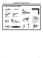 4
4
-
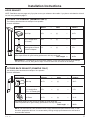 5
5
-
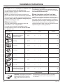 6
6
-
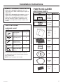 7
7
-
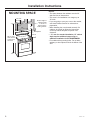 8
8
-
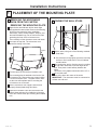 9
9
-
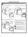 10
10
-
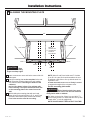 11
11
-
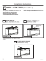 12
12
-
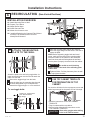 13
13
-
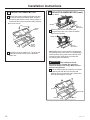 14
14
-
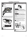 15
15
-
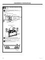 16
16
-
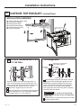 17
17
-
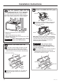 18
18
-
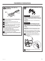 19
19
-
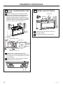 20
20
-
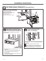 21
21
-
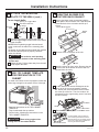 22
22
-
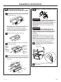 23
23
-
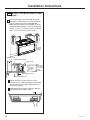 24
24
-
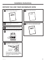 25
25
-
 26
26
-
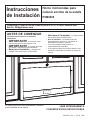 27
27
-
 28
28
-
 29
29
-
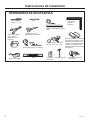 30
30
-
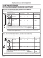 31
31
-
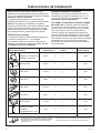 32
32
-
 33
33
-
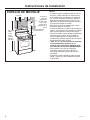 34
34
-
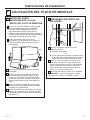 35
35
-
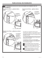 36
36
-
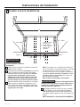 37
37
-
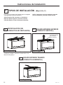 38
38
-
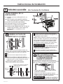 39
39
-
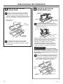 40
40
-
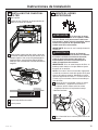 41
41
-
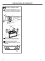 42
42
-
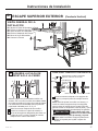 43
43
-
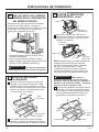 44
44
-
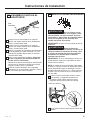 45
45
-
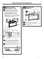 46
46
-
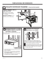 47
47
-
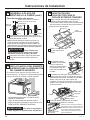 48
48
-
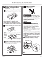 49
49
-
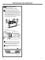 50
50
-
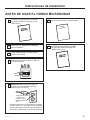 51
51
-
 52
52


GE PVM9005BLTS Guía de instalación
- Categoría
- Microondas
- Tipo
- Guía de instalación
- Este manual también es adecuado para
En otros idiomas
- English: GE PVM9005BLTS Installation guide
Documentos relacionados
-
GE CVM721M2NS5 Guía de instalación
-
GE Profile PSA9120SFSS Guía de instalación
-
GE PVM9005DJWW Guía de instalación
-
GE PSA9240SPSS Guía de instalación
-
GE JNM3163DJBB Guía de instalación
-
GE Appliances JVM3160DFCC Manual de usuario
-
GE JVM3160 Guía de instalación
-
-
GE Cafe Series CSA1201RSS Guía de instalación
-
GE JNM7196DKBB Template