49-40752-3 27
Instrucciones de instalación
INSTRUCCIONES DE SEGURIDAD IMPORTANTES
Este producto requiere un tomacorriente eléctrico
de tres patas conectado a tierra. El instalador debe
llevar a cabo una inspección de continuidad a tierra
en la caja eléctrica antes de comenzar la instalación
para asegurar que la caja tomacorriente está
conectada
a tierra de manera apropiada. Si no lo está, o si
el tomacorriente no cumple con los requisitos
eléctricos indicados (bajo la sección REQUISITOS
ELÉCTRICOS), se deberá recurrir a un técnico
calificado para corregir cualquier
deficiencia.
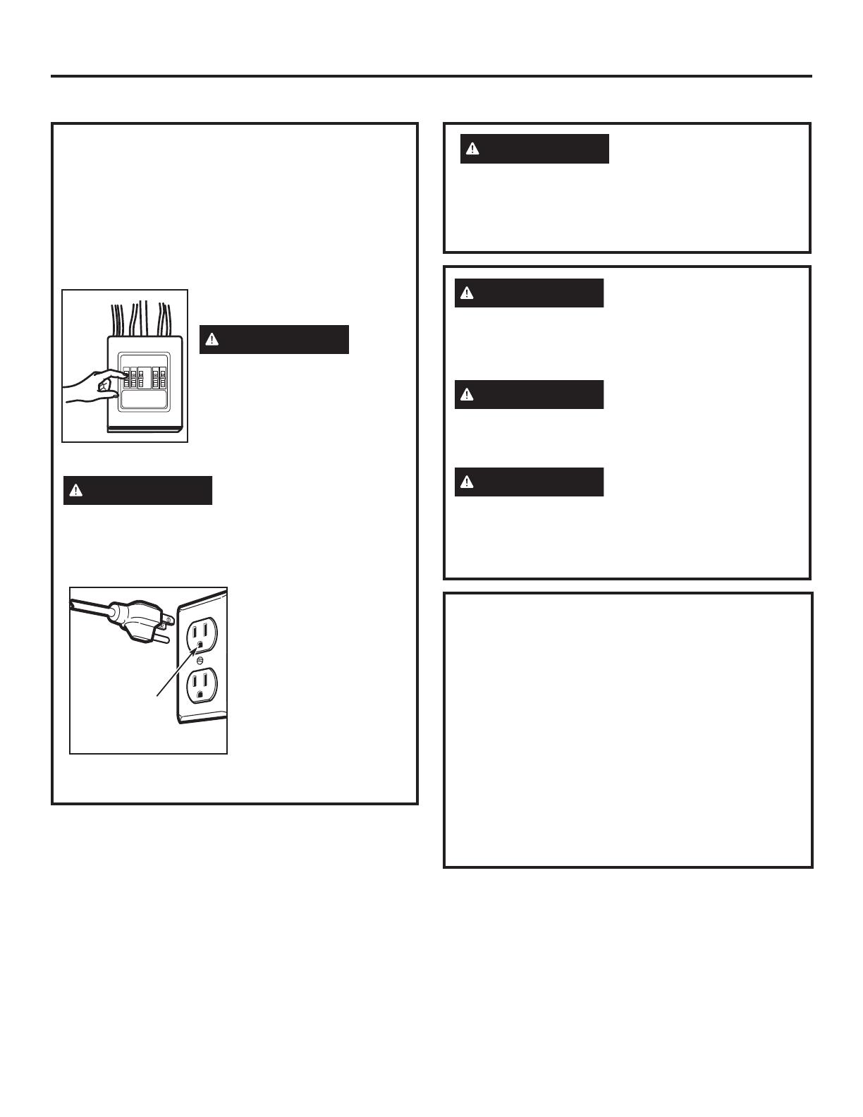
PRECAUCIÓN
Para seguridad personal,
remueva el fusible de la casa
o abra el interruptor de circuito
antes de comenzar la instalación
para evitar descargas eléctricas
severas o fatales
ADVERTENCIA
Riesgo de Descarga
Eléctrica. Puede ocasionar lesiones o la muerte:
ESTE ELECTRODOMÉSTICO SE DEBE CONECTAR
A TIERRA DE FORMA CORRECTA a fin de evitar
descargas severas o mortales.
Modelos de 120 V
El cable de corriente de
este electrodoméstico
contiene un enchufe de 3
patas (conexión a tierra)
que se conecta a un
tomacorriente de pared
estándar de 3 cables
(conexión a tierra) para
minimizar la posibilidad
de riesgos de descargas
eléctricas por parte del
mismo.
REQUISITOS ELÉCTRICOS
Modelos de 120 V
La clasificación del producto es de 120 vatios CA
(AC), 60 hertz, 15 amperios, y 1.70 kilovatios.
Este producto debe estar conectado a un circuito
de suministro del voltaje y frecuencia apropiados.
El tamaño del alambre debe conformarse a los
requisitos del National Electric Code o al código local
en efecto para este índice de kilovatios. El cable
eléctrico de alimentación y el interruptor deberán
llevarse a un tomacorriente único conectado a tierra
de 15 a 20 amperios. La caja del tomacorriente
deberá estar localizada en el gabinete encima del
horno. La caja del tomacorriente debe ser instalada
por un electricista calificado y debe conformarse al
National Electrical Code o al código local en efecto.
Asegúrese de
contar con una
conexión a
tierra adecuada
antes de usar.
ADVERTENCIA
Riesgo de Descarga
Eléctrica. Puede ocasionar lesiones o la muerte:
NUNCA, bajo ninguna circunstancia, corte, deforme
o elimine ninguna de las puntas de los cables de
corriente. No use un prolongador. Si no se cumple
con esto, se podrán producir incendios..
PRECAUCIÓN
Por razones de seguridad,
la superficie de montaje deberá poder soportar la
carga del gabinete, sumado al peso agregado de
este producto de entre 63 y 85 libras, además de
cargas adicionales en el horno de hasta 50 libras o
un peso total de entre 113 y 135 libras.
PRECAUCIÓN
Por razones de seguridad,
este producto no se puede instalar en arreglos de
gabinete tales como una isla o península. Se debe
montar TANTO a un gabinete superior COMO a una
pared.
PRECAUCIÓN
A fin de evitar el riesgo
de lesión personal (lesión en la espalda u otras
lesiones debido a peso excesivo del horno de
microondas) o daños sobre el producto, deberá
contar con la ayuda de dos personas para instalar
este horno de microondas..


