Yamaha RX-V10MKII El manual del propietario
- Categoría
- Receptor
- Tipo
- El manual del propietario

OWNER’S MANUAL
MODE D’EMPLOI
BEDIENUNGSANLEITUNG
BRUKSANVISNING
MANUALE DI ISTRUZIONI
MANUAL DE INSTRUCCIONES
GEBRUIKSAANWIJZING
AV RECEIVER
AMPLI-TUNER AUDIO-VIDEO
RX-V10MK
II
B G R

1. To assure the finest performance, please read this manual
carefully. Keep it in a safe place for future reference.
2. Install this unit in a cool, dry, clean place – away from
windows, heat sources, sources of excessive vibration,
dust, moisture and cold. Avoid sources of humming
(transformers, motors). To prevent fire or electrical shock,
do not expose the unit to rain or water.
3. Never remove the unit cover. Contact your dealer if an
object falls inside the unit.
4. Do not use force on switches, controls or connection wires.
When moving the unit, first disconnect the power plug and
the wires connected to other equipment. Never pull on the
wires themselves.
5. The openings on the unit cover assure proper ventilation of
the unit. If these openings are obstructed, the temperature
inside the unit will rise rapidly. Therefore, avoid placing
objects against these openings, and install the unit in a
well-ventilated area to prevent fire and damage.
<Europe and U.K. models only>
Be sure to allow a space of at least 20 cm behind, 20 cm
on the both sides and 30 cm above the top panel of the
unit to prevent fire and damage.
6. The voltage used must be the same as that specified on
this unit. Using this unit with a higher voltage than
specified is dangerous and may result in fire or other
accidents. YAMAHA will not be held responsible for any
damage resulting from use of this unit with a voltage other
than specified.
7. Always set the VOLUME control to “0” before starting the
audio source play. Increase the volume gradually to an
appropriate level after playback has been started.
8. Do not attempt to clean the unit with chemical solvents;
this might damage the finish. Use a clean, dry cloth.
9. Be sure to read the “TROUBLESHOOTING” section
regarding common operating errors before concluding that
the unit is faulty.
10.When not planning to use this unit for long periods of time,
disconnect the AC power plug from the wall outlet.
11.To prevent lightning damage, disconnect the AC power
plug and antenna cable when there is an electrical storm.
12.Grounding or polarization – Precautions should be taken
so that the grounding or polarization of an appliance is not
defeated.
13.Do not connect audio unit to the AC outlet on the rear
panel if the equipment requires more power than the outlet
is rated to provide.
14.Voltage Selector (General Model only)
The voltage selector on the rear panel of this unit must
be set for your local main voltage BEFORE plugging
into the AC main supply.
Voltages are 110/120/220/240 V AC, 50/60 Hz.
This unit is not disconnected from the AC power source as
long as it is connected to the wall outlet, even if this unit
itself is turned off. This state is called the standby mode.
In this mode, this unit is designed to consume a small
amount of power.
IMPORTANT
Please record the serial number of your unit in the space
below.
Model:
Serial No.:
The serial number is located on the rear of the unit.
Retain this Owner’s Manual in a safe place for future
reference.
WARNING
TO REDUCE THE RISK OF FIRE OR ELECTRIC SHOCK,
DO NOT EXPOSE THIS UNIT TO RAIN OR MOISTURE.
FREQUENCY STEP switch (General Model only)
Because the interstation frequency spacing differs in
different areas, set the FREQUENCY STEP switch (located
at the rear) according to the frequency spacing in your area.
Before setting this switch, disconnect the AC power plug of
this unit from the AC outlet.
For U.K. customers
If the socket outlets in the home are not suitable for the plug
supplied with this appliance, it should be cut off and an
appropriate 3 pin plug fitted. For details, refer to the
instructions described below.
Note: The plug severed from the mains lead must be
destroyed, as a plug with bared flexible cord is hazardous if
engaged in a live socket outlet.
Special Instructions for U.K. Model
IMPORTANT
THE WIRES IN MAINS LEAD ARE COLOURED IN
ACCORDANCE WITH THE FOLLOWING CODE:
Blue: NEUTRAL
Brown: LIVE
As the colours of the wires in the mains lead of this
apparatus may not correspond with the coloured markings
identifying the terminals in your plug, proceed as follows:
The wire which is coloured BLUE must be connected to the
terminal which is marked with the letter N or coloured
BLACK. The wire which is coloured BROWN must be
connected to the terminal which is marked with the letter L
or coloured RED. Making sure that neither core is
connected to the earth terminal of the three pin plug.
2
CAUTION : READ THIS BEFORE OPERATING YOUR UNIT.

3
English
CAUTION ...................................................................2
FEATURES ................................................................4
PROFILE OF THIS UNIT ...........................................5
GETTING STARTED .................................................6
Unpacking ..................................................................6
Opening and closing the front cover ...........................6
Installing batteries in the remote controller ................7
Using the remote controller ........................................7
SPEAKER SET UP ....................................................8
CONNECTIONS .........................................................9
Connecting audio and video components ..................9
Connecting speakers ...............................................12
Connecting antennas ...............................................14
CONTROLS AND THEIR FUNCTIONS ..................16
Front panel ...............................................................16
Remote controller .....................................................18
Display panel ............................................................20
SPEAKER BALANCE ADJUSTMENT.....................21
PLAYING AND RECORDING A SOURCE .............24
Playing a source .......................................................24
Recording a source to tape (or MD) .........................25
Sound control ...........................................................26
BASIC TUNING OPERATION .................................27
Automatic tuning ......................................................27
Manual tuning ...........................................................27
PRESET TUNING ....................................................28
Manual preset tuning ................................................28
Automatic preset tuning ...........................................29
Exchanging preset stations ......................................30
RECEIVING RDS STATIONS
<Europe and U. K. models only>.........................31
Displaying RDS data ................................................31
Selecting your desired program type from
among preset RDS stations (PTY SEEK) ................34
Automatic selection of desired program
when broadcasting starts .........................................35
USING DIGITAL SOUND FIELD PROCESSOR
(DSP) ........................................................................36
Brief overview of Digital Sound Field Programs .......36
Playing a source with an effect of the digital
sound field processor (DSP) ....................................37
TROUBLESHOOTING .............................................40
SPECIFICATIONS ...................................................41
CONTENTS
Thank you for selecting this YAMAHA AV receiver.

4
●
5 Speaker Configuration
(Power Amp. Section)
Main: 45W + 45W (8Ω) RMS Output
Power, 0.04% THD, 20–20,000 Hz
Center: 45W (8Ω) RMS Output
Power, 0.04% THD, 1 kHz
Rear: 15W + 15W (8Ω) RMS Output
Power, 0.3% THD, 1 kHz
●
Digital Sound Field Processor
●
Dolby Pro Logic Surround Decoder
●
Theater-like Sound Experience by the
Combination of Dolby Pro Logic and
YAMAHA DSP Technology (CINEMA DSP)
●
Automatic Input Balance Control for
Dolby Pro Logic Surround
●
Test Tone Generator for Easier Speaker
Balance Adjustment
●
3 Center Channel Modes
(NORMAL/WIDE/PHANTOM)
● 40-Station Random Access Preset Tuning
● Automatic Preset Tuning
● Preset Station Shifting Capability (Preset
Editing)
● IF Count Direct PLL Synthesizer Tuning
System
● On Screen Display Function Helpful in
Controlling This Unit
● 6-Channel Discrete Input Terminals for
Connecting with a Dolby Digital or
Another 5.1-channel Decoder
● Video Signal Input/Output Capability
● SLEEP Timer
● Remote Control Capability
<
Europe and U.K. models only
>
● Multi-Functions for RDS Broadcast
Reception
FEATURES

5
English
PROFILE OF THIS UNIT
You are the proud owner of a Yamaha stereo receiver –an extremely sophisticated audio component. The Digital Sound Field
Processor (DSP) built into this unit takes advantage of Yamaha’s undisputed leadership in the field of digital audio processing to
bring you a whole new world of listening experiences. Follow the instructions in this manual carefully when setting up your system,
and this unit will sonically transform your room into a wide range of listening environments –movie theater, concert hall, and so on.
In addition, you get incredible realism from sources encoded with Dolby Surround using the built-in Dolby Pro Logic Surround
Decoder.
Please read this operation manual carefully and store it in a safe place for later reference.
Digital Sound Field Processing
Technological advances in sound reproduction over the last 30
years have enhanced the listening experience with improved
clarity, precision and power. However, something has still been
missing: The atmosphere and acoustic ambiance of the public
venue. Our Yamaha engineers have extensively researched
the nature of sound acoustics and the way sound reflects
inside a room. We sent these engineers to famous theaters
and concert halls around the world to measure the acoustics of
those venues with sophisticated microphones. The data they
collected is used to recreate these environments in digital
sound fields. Some of these digital sound fields are created
using data measured directly at the original venue; others are
created from combinations of data to form unique
environments for specific purposes.
You can use these sound fields to enhance any source and in
combination with the Dolby Pro Logic Surround technology.
Some are designed especially for music, and some especially
for movies.
Dolby Pro Logic Surround
Dolby Pro Logic Surround has been used in movie theaters
since the mid-seventies. It has also been available in home
entertainment systems since the late eighties and continues to
be a popular format for home theater systems. It uses four
discrete channels and five speakers to reproduce realistic and
dynamic sound effects: two main channels (left and right), a
center channel for dialog, and a rear channel for special sound
effects. The rear channel reproduces sound within a narrow
frequency range.
Most video tapes and laser discs include Dolby Pro Logic
Surround encoding as do many TV and cable broadcasts. The
Dolby Pro Logic Surround decoder built into this unit employs a
digital signal processing system that stabilizes each channel
for even more accurate sound positioning than is available with
standard analog processors.
Manufactured under license from Dolby Laboratories Licensing
Corporation. DOLBY, the double-D symbol and PRO LOGIC
are trademarks of Dolby Laboratories Licensing Corporation.
Dolby Pro Logic Surround + DSP
The Dolby Surround sound system shows its full ability in a
large movie theater, because movie sounds are originally
designed to be reproduced in a large movie theater that uses a
multitude of speakers. Trying to create a sound environment
similar to that of a movie theater in your home is difficult
because of the room size, material inside the walls, number of
speakers, and so on. In other words, your listening room is
very different from a movie theater.
However, Yamaha DSP technology allows you to create nearly
the same sound experience as that of a large movie theater in
your home by compensating for the lack of presence and
dynamics in the listening room with its original digital sound
fields combined with Dolby Surround sound field.
The combination of Dolby Pro Logic Surround and DSP is used
on the sound field program “ PRO LOGIC ENHANCED”.
The YAMAHA “CINEMA DSP” logo indicates these programs that
are created by the combination of Dolby Pro Logic and YAMAHA
DSP technology.
CINEMA DSP

6
m Opening and closing the front cover
Close the front cover whenever the controls inside the panel are not used.
To open the front cover To close the front cover
Indoor FM Antenna
AM Loop Antenna
75-ohm/300-ohm antenna adapter (U.K. model only)
Remote Controller
Batteries (size AA, R6, UM-3)
m Unpacking
Carefully remove this unit and accessories from the box. You should find the unit itself and the following accessories.
REC/PAUSE
DIR BDIR A
PLAY
DISC
POWER
/I
VOLUME
PLAY
DVD/LD
2CH/6CH
PRESET
A/B/C/D/E
–+
LEVEL
DELAY/CENTER
/REAR/SWFR
TEST
EFFECT
PROGRAM
PROLOGIC
ENHANCED
–+
SLEEP
TAPE
A/B
ON/OFF
TUNER
CD
PHONO
VCRV-AUX
GETTING STARTED

Remote controller operation range
Notes
●
The area between the remote controller and the main unit
must be clear of large obstacles.
●
Do not expose the remote control sensor to strong lighting,
in particular, an inverter type fluorescent lamp. Otherwise,
the remote controller may not work properly. If necessary,
position the main unit away from direct lighting.
7
English
Since the remote controller will be used for many of this unit’s
control operations, you should begin by installing the supplied
batteries.
1.Turn the remote controller over and slide the battery
compartment cover in the direction of the arrow.
2.Insert the batteries (R6, AA, UM-3 type) according to the
polarity markings on the inside of the battery compartment.
3.Close the battery compartment cover.
Battery replacement
If you find that the remote controller must be used closer to the
main unit, the batteries are weak. Replace both batteries with
new ones.
Notes
●
Use only AA, R6, UM-3 batteries.
●
Be sure the polarities are correct. (See the illustration inside
the battery compartment.)
●
Remove the batteries if the remote controller is not used for
an extended period of time.
●
If batteries leak, dispose of them immediately. Avoid
touching the leaked material and contact with clothing, etc.
Clean the battery compartment thoroughly before installing
new batteries.
1
3
2
30°
30°
Remote control
sensor
Within approximately
6 m (19.7 feet)
m Using the remote controller
m Installing batteries in the remote controller

8
SPEAKER SETUP
Speakers to be used
This unit is designed to provide the best sound-field quality with a 5-speaker configuration. The most effective speakers to use with
this unit are main speakers, rear speakers, and a center speaker. You can do without the center speaker. (Refer to the “4-Speaker
Configuration” shown below.)
The main speakers are used for the main source sound. They could be the speakers from your present stereo system. The rear
speakers are used for the effect and surround sounds, and the center speaker is for the center sounds (dialog etc.) within programs
encoded with Dolby Surround. The center speaker needs to be equal in power to the main speakers, although the rear speakers do
not have to be equal. However, all the speakers should have high enough power handling to accept the maximum output of this
unit.
Speaker configuration
5-Speaker Configuration
This configuration is the most effective and recommended one.
In this configuration, the center speaker is necessary as well as
the rear speakers. If the program PRO LOGIC or
PRO LOGIC ENHANCED is selected, conversations will be
output from the center speaker and the ambience will be
excellent.
• Set the center channel mode to the “NORMAL” or “WIDE”
position. (For details, refer to page 22.)
4-Speaker Configuration
The center speaker is not used in this configuration. If the
program PRO LOGIC or PRO LOGIC ENHANCED is
selected, the center sound is output from the left and the right
main speakers. However, the sound effect of other DSP
programs can be the same as that of the 5-speaker
configuration.
• Be sure to set the center channel mode to the “PHANTOM”
position. (For details, refer to page 22.)
Speaker placement
The recommended speaker configuration, the 5-speaker configuration, will require two speaker pairs: main speakers (your normal
stereo speakers), and rear speakers, plus a center speaker. When you place these speakers, refer to the following.
Main: The position of your present stereo speaker system.
Rear: Behind your listening position, facing slightly inward.
Nearly 1.8m (approx. 6 feet) above the floor.
Center: Precisely between the main speakers. (To avoid
interference with TV sets, use a magnetically shielded
speaker.)
Front L Center Front R
Dialogue
Surround sound
Dialogue
Surround sound
Rear L
Rear R
Front L Front R
Dialogue
Surround sound
Dialogue
Surround sound
Rear L Rear R
Front R
Center
Front L
TV set
Rear R
Rear L
Main L
Main R
Main L
Main R
Main L
Main R

9
English
CONNECTIONS
Caution: Plug in this unit and other components after all connections are completed.
m Connecting audio and video components
All connections must be correct, that is to say L (left) to L, R (right) to R, “+” to “+” and “–” to “–”. Also refer to the owner’s manual
for each of your components.
* The output (or input) terminals of YAMAHA components numbered as 1, 3, 4, etc. on the rear panel must be connected to the
same-numbered terminals of this unit.
(* 1), (* 2) : See page 10.
MONITOR
OUT
IN
OUT
IN
PHONO
V
-
AUX
GND
IN CD
OUT
GND
FM
ANT
75Ω
UNBAL
.
AM
ANT
DVD
/LD
1
OUT
3
4
DVD
/LD
I00W MAX.
TOTAL
TAPE
/MD
VCR
VIDEO
SWITCHED
REAR
CENTER
REAR
8
Ω
MIN.
/SPEAKER
8
Ω
MIN./SPEAKER
OUT
SUB
WOOFER
VIDEO
SIGNAL
AUDIO SIGNAL
VCR
SPEAKERS
SUB
WOOFER
MAIN
MAIN
SURROUND
DVD/LD
6CH DISCRT INPUT
AC OUTLETS
CENTER
VIDEO IN
GND
OUTPUT
AUDIO OUT
VIDEO OUT
AUDIO IN
VIDEO IN
AUDIO OUT
VIDEO OUT
OUTPUT
LINE OUT
LINE IN
AUDIO OUT
VIDEO OUT
(Europe model)
To AC outlet
Tape deck,
MD recorder, etc.
Video cassette
recorder
Turntable
LD player,
DVD player, etc.
CD player
TV monitor
TV/Satellite tuner, etc.
(* 2)
(* 1)

10
If you connect a VCR, LD player, video monitor, etc. to this
unit, you can display DSP program names and information
about other settings and adjustments on the video monitor
screen. Information is superimposed over the video image.
If there is no image on the monitor, the information will be
displayed over a monochromatic background.
TV MODE PAL/NTSC switch (General model only)
This unit is designed for use with the NTSC and PAL
television formats. Set this switch to the position for the
format your TV monitor employs.
PAL: Set to this position if your TV monitor employs the
PAL format.
* Outputs signals in the PAL format no matter which
format (PAL or NTSC) of video signal is sent from
an external video unit to this unit.
NTSC: Set to this position if your TV monitor employs the
NTSC format.
* Outputs signals in the NTSC format no matter
which format (PAL or NTSC) of video signal is
sent from an external video unit to this unit.
Note
Be sure to input a video signal which employs the same
format that your TV monitor employs, otherwise a picture will
not be played back normally.
ON SCREEN display
MONITOR
OUT
TV
MODE
CD
1
VIDEO
NTSC
PAL
REAR
CENTER
REAR
8
Ω
MIN.
/SPEAKER
OUT
SUB
WOOFER
TV MODE PAL/NTSC switch
AC OUTLETS (SWITCHED)
(Europe and General models)........... 2 SWITCHED OUTLETS
(U.K. model)......................................... 1 SWITCHED OUTLET
Use these to connect the power cords of your components to
this unit.
The power to the SWITCHED outlets is controlled by this unit’s
STANDBY/ON switch or the remote controller’s POWER /I
key. These outlets will supply power to any component
whenever this unit is turned on.
The maximum power (total power consumption of components)
that can be connected to the SWITCHED AC OUTLETS is 100
watts.
GND terminal (For turntable use)
Connecting the ground wire of the turntable to the GND
terminal will normally minimize hum, but in some cases better
results may be obtained with the ground wire disconnected.
(* 1):
(* 2):

11
English
Connecting with 6 channel discrete outputs of a Dolby Digital decoder, DTS decoder or DVD player,
etc.
If you have a Dolby Digital decoder, DTS decoder or a DVD player etc. which incorporates a Dolby Digital decoder, DTS decoder or
MPEG 2 decoder, its 6 channel discrete outputs can be connected to the DVD/LD 6CH DISCRT INPUT terminals of this unit.
Notes
• The LD or DVD player must be also connected to the
DVD/LD AUDIO SIGNAL input terminals of this unit for
playing a source with Dolby Pro Logic Surround decoded or
in 2-channel stereo (or monaural).
• The discrete signals input to this unit cannot be recorded by
a tape deck, MD recorder or VCR. To record a source played
on the LD or DVD player, it must be connected to the
DVD/LD AUDIO/VIDEO SIGNAL input terminals of this unit.
• If you made no connection to the SUBWOOFER input
terminal of this unit or you will not use a subwoofer, you must
make a setting on the Dolby Digital decoder etc. so that
signals at the SUBWOOFER channel are distributed to the
right and left MAIN output terminals of the Dolby Digital
decoder etc.
For details, refer to the owner’s manual for the Dolby Digital
decoder etc.
Dolby Digital decoder
RF
Demodulator
LD player with DOLBY DIGITAL
RF output
An example of connections:
OUTPUT
MAIN CENTER SURROUND
SUBWOOFER
DIGITAL
IN
DOLBY
DIGITAL
RF OUT
VIDEO
OUT
AUDIO
OUT
1
3
MONITOR
OUT
IN
OUT
IN
PHONO
V
-
AUX
GND
IN CD
OUT
GND
FM
ANT
75
Ω
UNBAL
.
AM
ANT
DVD
/LD
OUT
4
DVD
/LD
TAPE
/MD
VCR
VIDEO
OUT
SUB
WOOFER
VIDEO
SIGNAL
AUDIO SIGNAL
VCR
SUB
WOOFER
MAIN
CENTER
SURROUND
DVD/LD
6CH DISCRT INPUT
DOLBY
DIGITAL
RF IN
DIGITAL
OUT

12
m Connecting speakers
REAR
CENTER
REAR
8
Ω
MIN./SPEAKER
OUT
SUB
WOOFER
SPEAKERS
SUB
WOOFER
MAIN
CENTER
SURROUND
DVD/LD
6CH DISCRT INPUT
8
Ω
MIN.
/SPEAKER
MAIN
Rear speaker Rear speaker
Center speaker
Main speaker
Left
Right
Subwoofer system
Left
Right
(Europe model)
Note
Use speakers with the specified impedance
shown on the rear of this unit.
For connecting to the MAIN SPEAKERS terminals
Red: positive (+)
Black: negative (–)
➀
Loosen the knob.
➁
Insert the bare wire.
[Remove approx. 5mm
(1/4”) insulation from
the speaker wires.]
➂
Tighten the knob and
secure the wire.
<General model only>
Banana Plug connections are also possible. Simply insert the
Banana Plug connector into the corresponding terminal.
1
2
3
How to Connect:
Connect the SPEAKERS terminals to your speakers with the wire of the proper gauge (keep as short as possible). If the
connections are faulty, no sound will be heard from the speakers. Make sure that the polarity of the speaker wires is correct. That is
the + and – markings are observed. If these wires are reversed, the sound will be unnatural and lack bass.
Caution
Do not let the bare speaker wires touch each other or any metal part of this unit. This could damage this unit or the
speakers, or both.
Main speaker

For connecting to the REAR and CENTER SPEAKERS
terminals
Red: positive (+)
Black: negative (–)
➀
Press the tab.
➁
Insert the bare wire.
[Remove approx. 5mm
(1/4”) insulation from
the speaker wires.]
➂
Release the tab and
secure the wire.
13
English
Note on a subwoofer connection:
You may wish to add a subwoofer to reinforce low frequencies
or to output low bass sound from the subwoofer channel when
reproducing discrete signals.
When using a subwoofer, connect the SUBWOOFER OUT
terminal of this unit to the INPUT terminal of the subwoofer
amplifier, and connect the speaker terminals of the subwoofer
amplifier to the subwoofer.
With some subwoofers, including the Yamaha Active Servo
Processing Subwoofer System, the amplifier and subwoofer
are in the same unit. Such a subwoofer needs only the
connection between the SUBWOOFER OUT terminal of this
unit and the INPUT terminal of the subwoofer.
SUBWOOFER OUT terminal
This terminal is for connecting with the input terminal of an
amplifier for driving a subwoofer.
When the input signals to this unit are normal 2-channel
stereo, this terminal outputs low frequencies from the main
and center channels. (The frequency cut-off of this
terminal is at 150 Hz.) When the source equipment
connected to the DVD/LD 6CH DISCRT INPUT terminals
of this unit is selected as the input source, this terminal
outputs signals from the subwoofer channel.
REAR
CENTER
REAR
OUT
SUB
WOOFER
8
Ω
MIN.
/SPEAKER
➁
➂
➀

Connecting the AM loop antenna
1.Press the tab and unlock the terminal hole.
2.Connect the AM loop antenna lead wires to the AM ANT
and GND terminals.
3.Return the tab back to the original position to lock the lead
wires. Lightly pull on the lead wires to confirm a good
connection.
4.Attach the loop antenna to the antenna stand.
5.Orient the AM loop antenna so that the best reception is
obtained.
Notes
●
The AM loop antenna should be placed apart from the
main unit. The antenna may be hung on a wall.
●
The AM loop antenna should be kept connected, even if
an outdoor AM antenna is connected to this unit.
14
m Connecting antennas
●
Each antenna should be connected to the designated terminal(s) correctly, as shown in the following figure.
●
Both AM and FM indoor antennas are included with this unit. In general, these antennas will provide sufficient signal strength.
Nevertheless, a properly installed outdoor antenna will give clearer reception than an indoor one. If you experience poor reception
quality only with the indoor antennas, the use of an outdoor antenna may result in improvement.
IN
PHONO
V
-
AUX
GND
IN
OUT
GND
FM
ANT
75
Ω
UNBAL
.
AM
ANT
DVD
/LD
OUT
3
4
TAPE
/MD
VCR
AUDIO SIGNAL
Outdoor FM antenna
Antenna stand
Loop antenna
Outdoor AM antenna
AM loop
antenna
(included)
Ground
75-ohm/300-ohm
antenna adapter
75-ohm/300-ohm
antenna adapter
75-ohm coaxial cable
300-ohm flat ribbon cable
Indoor FM
antenna
(included)
(Europe model)
1
2
3

Optional outdoor AM antenna
If this unit is placed in steel buildings or an area far from broadcasting stations, it may be necessary to install an outside long wire
antenna.
15
English
Optional outdoor FM antenna
Consult your dealer or authorized service center about the best
method of selecting and erecting an outdoor FM antenna.
The choice of the flat ribbon cable is also important. Flat ribbon
cable performs well electrically, and is cheaper and somewhat
easier to handle when routing it through windows and around
rooms. Coaxial cable is more expensive, does a much better
job of minimizing interference, is less prone to the effects of
weather and close-by metal objects, and is nearly as good a
signal conductor as flat ribbon cable. Coaxial cable is
somewhat more difficult to install at the point where the cable
enters the building. If coaxial cable is selected, make sure the
antenna is designed to be used with this type of cable.
* Use a 75-ohm/300-ohm antenna adapter (not included) or a
75-ohm antenna adapter (not included) for connections.
300-ohm flat ribbon cable 75-ohm coaxial cable
75-ohm/300-ohm antenna adapter
Notes for FM antenna installation
●
To minimize the influence of automobile ignition noise,
locate the antenna as far from heavy traffic as possible.
●
Keep the flat ribbon cable or coaxial cable as short as
possible. Do not bundle or roll up an excess of the cable.
●
The antenna should be at least two meters (6.6 feet) from
reinforced concrete walls or metal structures.
300-ohm flat
ribbon cable
75-ohm coaxial
cable
75-ohm antenna
adapter
75-ohm coaxial
cable
Connecting the indoor FM antenna
Connect the included indoor antenna to the 75Ω UNBAL.
FM ANT terminal.
Note
Do not use an outdoor FM antenna and the indoor FM
antenna at the same time.
GND terminal
For maximum safety and minimum interference, connect the
GND terminal to a good ground. A good ground is a metal
stake driven into moist earth.

1 STANDBY/ON switch
Press this switch to turn on the power. Press this switch again
to set this unit in the standby mode.
Standby mode
This unit is still using a small amount of power in this mode
in order to be ready to receive infrared-signals from the
remote controller.
2 Remote control sensor
Receives signals from the remote controller.
3 Display panel
Displays a variety of information. (Refer to page 20 for details.)
4 INPUT selector
Turn this knob to select the input source.
The selected source will be shown on the display.
PTY SELECTOR
<Europe and U.K. models only>
When this unit is in the PTY SEEK mode, tuning this control
changes the currently selected program type.
5 VOLUME control
Used to raise or lower the volume level.
6 Front cover
Refer to page 6 on how to open and close the front cover.
7 PHONES jack
Headphones can be plugged into this jack for private listening.
Only the sound signals from the main channels are output.
When listening with headphones privately, set the SPEAKERS
switch to the OFF position.
8 SPEAKERS switch
Press and set this switch inward (ON) to make the all speakers
and a subwoofer produce a sound.
Press and release this switch outward (OFF) to make the all
speakers and a subwoofer produce no sound.
16
CONTROLS AND THEIR FUNCTIONS
m Front panel
SPEAKERS
OFFON
A
/
B
/
C
/
D
/
E
PRESET STATIONS
TUNING
KEY MODE
TUNING
MODE
FM
/
AM
MEMORY PROGRAM
CENTER
MODE
EDIT
AUTO
/
MAN’L MONO MAN’L
/
AUTO FM
BASS TREBLE BALANCE
0
–+
0
–+
LR
INPUT
DVD-LD/ VCR /V-AUX/TAPE•MD/CD / TUNER/ PHONO
VOLUME
0I0
STANDBY/ON
PHONES
NATURAL SOUND AV RECEIVER
RX–V10MK
EON
PTY SEEK
MODE START
PTY SELECTOR
12 3
EF
45
0AB D689 C IJ KGH
L7
6CH/2CH
CINEMA DSP
RDS MODE
/
FREQ
Parts in the shaded areas are provided for Europe and U.K. models only.
PHONES

17
English
9 RDS MODE/FREQ button
<Europe and U.K. models only>
When an RDS station is received, pressing this button changes
the display mode into the PS mode, PTY mode, RT mode, and
frequency display in turn.
0 PTY SEEK MODE button
<Europe and U.K. models only>
Turns the unit into the PTY SEEK mode.
A PTY SEEK START button
<Europe and U.K. models only>
Begins searching for a station after the desired program type is
selected in the PTY SEEK mode.
B EON button
<Europe and U.K. models only>
Selects the desired program type (NEWS, INFO, AFFAIRS,
SPORT) when you want to call a radio program of the program
type automatically.
C FM/AM button
Press this button to switch the reception band between FM and
AM.
D A/B/C/D/E button
Press this button to select a group (A to E) of preset stations.
E TUNING MODE (AUTO/MAN’L MONO) button
Press this button to switch the tuning mode between automatic
and manual. To select the automatic tuning mode, press this
button so that the “AUTO” indicator is illuminated on the
display. To select the manual tuning mode, press this button so
that the “AUTO” indicator is not illuminated.
F MEMORY (MAN’L/AUTO FM) button
Use this button to enter a station to memory. Refer to the
section “Manual preset tuning” on page 28 for details.
Hold down this button for more than 3 seconds to start
automatic preset tuning. Refer to page 29 for details.
G PRESET STATIONS/TUNING button
This button is used for the PRESET STATIONS function when
“PRESET” is illuminated on the display, and the TUNING
function when “PRESET” is not illuminated. The following
explains these functions in detail.
PRESET STATIONS :
Selects a preset station number (from 1 to 8).
Press the side to select a higher preset station number.
Press the side to select a lower preset station number.
TUNING :
Used for tuning. Press the side to tune in to a higher
frequency, and press the side to tune in to a lower
frequency.
H CENTER MODE button
Selects a center channel output mode (NORMAL, WIDE or
PHANTOM). (For details, refer to page 22.)
I PROGRAM button
When this button is repeatedly pressed, the built-in digital
sound field processor turns on, then the selected DSP program
changes to another program one by one, then the digital sound
field processor turns off, and repeated.
J KEY MODE/EDIT button
Press this button to alternately illuminate and turn off
“PRESET” on the display panel
. This button switches the
function of the PRESET STATIONS/TUNING button.
This button is also used to exchange the places of two preset
stations with each other.
K Tone controls
These controls are effective only for the sound from the main
speakers.
BASS
Used to increase or decrease the low frequency response.
The 0 position produces flat response.
TREBLE
Used to increase or decrease the high frequency response.
The 0 position produces flat response.
L BALANCE control
This knob controls the sound from the main speakers only.
The balance of the output volume to the left and right main
speakers can be adjusted to compensate for sound imbalances
caused by the speaker location or listening room conditions.

18
m Remote controller
The remote controller provided with this unit is designed to control the most commonly used functions. If the CD player or tape deck
is a YAMAHA component with remote control compatibility, this remote controller will also control various functions.
For Control of This Unit
1 DELAY/CENTER/REAR/SWFR and LEVEL +/– keys
Adjust the delay time (DELAY), the center channel output level
(CENTER), the rear channel output level (REAR) and the
output level to the SUBWOOFER OUT terminal (SWFR).
Select the item which you want to adjust by pressing the
DELAY/CENTER/REAR/SWFR key and adjust its time or level
by pressing the LEVEL +/– key.
(For details, refer to pages 23, 26, 38 and 39.)
2 Program selector keys
PROGRAM:
When the built-in digital sound field processor (including the
Dolby Pro Logic Surround decoder) is on, this key changes the
currently selected DSP program each time the right or left side
of this key is pressed.
PROLOGIC:
Directly selects the PRO LOGIC program.
ENHANCED:
Directly selects the PRO LOGIC ENHANCED program.
3 Tuner keys
Control tuners.
+: Press this key to select the next preset station number.
–: Press this key to select the previous preset station
number.
A/B/C/D/E: Selects the group (A to E) of preset station
numbers.
4 SLEEP timer key
This unit is automatically set in the standby mode one hour
after this key is pressed (so that the “SLEEP” indicator is
illuminated). To cancel this function, press this key again so
that the “SLEEP” indicator turns off.
5 POWER /I key
Turns on the power of this unit and sets this unit in the standby
mode alternately.
6 VOLUME +/– keys
Press these keys to increase or decrease the volume.
REC/PAUSE
DIR BDIR A
PLAY
DISC
VOLUME
PLAY
DVD/LD
2CH/6CH
PRESET
A/B/C/D/E
–+
LEVEL
DELAY//CENTER
/REAR/SWFR
TEST
EFFECT
PROGRAM
PROLOGIC
ENHANCED
–+
SLEEP
TAPE
A/B
ON/OFF
TUNER
CD
PHONO
VCR
1
2
3
4
5
2
8
7
9
6
V-AUX
1
POWER
/I

19
English
7 Input selector keys
Press a key to select the input source.
When the DVD/LD input source is selected, pressing the
DVD/LD key switches the input signals between 2 channel
stereo signals and 6 channel discrete signals. When switched
to “6ch”, discrete signals from the unit connected to the
DVD/LD 6CH DISCRT INPUT terminals of this unit are
selected as the input signals.
8 EFFECT ON/OFF key
Press this key to turn on/off the digital sound field processor,
which includes the Dolby Pro Logic Surround decoder.
9 TEST key
This key is used when adjusting the speaker balance. (Refer to
pages 21 to 23.)
For Other Component Control
Identify the remote controller keys with your component’s keys.
If these keys are identical, their functions will be the same. On
each key function, refer to the corresponding instruction on
your component’s manual.
1 Tape deck keys
Control tape decks.
* The DIR A, B and A/B keys apply only to double cassette
tape decks.
* Pressing the DIR A key will reverse the tape direction on a
single cassette tape deck with the automatic reverse
function.
2 CD player keys
Control compact disc players.
* The DISC is used for compact disc changers.

20
m Display panel
1 AUTO indicator
This indicator will be illuminated during the automatic tuning
mode.
2 MEMO indicator
A flashing MEMO indicator means a station can be saved, as
explained in the following:
Press the MEMORY button. The MEMO indicator will flash
about 5 seconds. While the indicator is flashing, program the
displayed station to memory by using the A/B/C/D/E and
PRESET STATIONS/TUNING buttons.
3 Preset station number indicator
Shows the selected group (A to E) and preset station number
(1 to 8).
4 Multi-information display
This display shows the status of adjustments and setting
changes. Several statuses can be viewed at one time. The
current station frequency and band (AM or FM) will also
appear when the tuner source input mode is selected.
5 STEREO indicator
This indicator will be illuminated when an FM stereo broadcast
with sufficient signal strength is received.
6 Signal-level meter
Indicates the signal level of the received station.
If multipath interference is detected, the indication decreases.
7 PTY H (HOLD) indicator
<Europe and U.K. models only>
This indicator will be illuminated while the search is performed
in the PTY SEEK mode.
8 RDS mode indicators
<Europe and U.K. models only>
The name(s) of RDS mode(s) employed by the currently
received RDS station will be illuminated. Illumination of the
indicator on the head of a name shows that the corresponding
RDS mode is now selected.
9 EON indicator
<Europe and U.K. models only>
This indicator will be illuminated when an RDS station that
employs the EON data service is received.
0 Program type name indicators
<Europe and U.K. models only>
The name selected in the EON mode will be illuminated.
A DSP program indicators
The name of the selected DSP program will be illuminated
when the built-in digital sound field processor or the Dolby Pro
Logic Surround decoder, or both of them are on.
B Center channel mode indicators
The name of the selected center channel mode (NORMAL,
WIDE or PHANTOM) will be illuminated only when the
PRO LOGIC or PRO LOGIC ENHANCED program is
selected.
C TEST indicator
Flashes when the built-in test tone generator is functioning
(when the test-tone is output from speakers).
D SLEEP indicator
This indicator will be illuminated when the built-in SLEEP timer
is functioning.
12
34 56
789
<AB
CD
TEST
PRESET
MEMO
AUTO
PTY H
PTY
PS RT
EON INFO SPORT
NEWS AFFAIRS
ST
0
MHz
l00
FM
SLEEP
WIDE
NORMAL
PHANTOM
CONCERT
HALL
CONCERT
VIDEO
PRO LOGIC
ENHANCED
ROCK
CONCERT
MONO
MOVIE
Indicators in the shaded areas are provided for Europe and U.K. models only.

21
English
1
Set to the “0” position.
2 Turn on the power.
3 Make sure that the SPEAKERS switch is set to the ON
position. If it is not so, press and set the SPEAKERS
switch inward (ON).
4
Set to the “0” position.
5 Select the PRO LOGIC or PRO LOGIC
ENHANCED program, so that the corresponding name
is illuminated on the display.
SPEAKER BALANCE ADJUSTMENT
This procedure lets you adjust the sound output level balance between the main, center, and rear speakers using the built-in test
tone generator. After the adjustments, the sound output level heard at the listening position will be the same from each speaker.
This is important for the best performance of the digital sound field processor and the Dolby Pro Logic Surround decoder.
The adjustment of each speaker output level should be done at your listening position with the remote controller.
BASS
0
–+
TREBLE
0
–+
BALANCE
LR
VOLUME
0I0
SPEAKERS
OFFON
21
3
STANDBY/ON
SPEAKERS
OFFON
A
/
B
/
C
/
D
/
E
PRESET STATIONS
TUNING
PTY SELECTOR
KEY MODE
TUNING
MODE
FM
/
AM MEMORY
PROGRAM
CENTER
MODE
EDIT
AUTO
/
MAN’L MONO MAN’L
/
AUTO FM
BASS TREBLE BALANCE
0
–+
0
–+
LR
INPUT
DVD-LD/ VCR/V-AUX/TAPE•MD/ CD/ TUNER/ PHONO
VOLUME
0I0
STANDBY/ON
PHONES
NATURAL SOUND AV RECEIVER
RX–V10MK
EON
PTY SEEK
MODE START
6CH/2CH
CINEMA DSP
RDS MODE
/
FREQ
4
CONTINUED
PROLOGIC
ENHANCED
REC/PAUSE
DIR BDIR A
PLAY
DISC
VOLUME
PLAY
DVD/LD
2CH/6CH
PRESET
A/B/C/D/E
–+
LEVEL
DELAY/CENTER
/REAR/SWFR
TEST
EFFECT
PROGRAM
PROLOGIC
ENHANCED
–+
SLEEP
TAPE
A/B
ON/OFF
TUNER
CD
PHONO
VCRV-AUX
POWER
/I
5

6 Select the center channel output mode suitable for your
speaker configuration.
(Refer to “Speaker configuration” on page 8.)
For the feature of each mode, refer to the “Note” shown
below.
7
Note
In step 6, when you select a center channel output mode, note
the following.
For 5-speaker configuration
NORMAL: Select this mode when you use a center speaker
that is smaller than the main speakers. In this
mode, the bass tone will be output from the main
speakers.
WIDE: Select this mode when you use the center speaker
approximately same sized as the main speakers.
For 4-speaker configuration
PHANTOM: Select this mode when you do not use the center
speaker. The center sound will be output from the
left and right main speakers.
8 Turn up the volume.
You will hear a test tone (like pink noise) from the left main
speaker, then the center speaker, then the right main
speaker, and then the rear speakers, for about two seconds
each. The display changes as shown below.
* The test tone from the left rear speaker and the right
rear speaker will be heard at the same time.
* The state of the test tone output is also shown on the
monitor screen by an image of the audio listening room.
This is convenient for adjusting each speaker level.
Main (L)
Rear
(L and R)
Center
Main (R)
22
VOLUME
0I0
CENTER
MODE
NORMAL
WIDE
PHANTOM
CONTINUED
8
SPEAKERS
OFFON
A
/
B
/
C
/
D
/
E
PRESET STATIONS
TUNING
PTY SELECTOR
KEY MODE
TUNING
MODE
FM
/
AM MEMORY
PROGRAM
CENTER
MODE
EDIT
AUTO
/
MAN’L MONO MAN’L
/
AUTO FM
BASS TREBLE BALANCE
0
–+
0
–+
LR
INPUT
DVD-LD/ VCR/V-AUX/TAPE•MD/ CD/ TUNER/ PHONO
VOLUME
0I0
STANDBY/ON
PHONES
NATURAL SOUND AV RECEIVER
RX–V10MK
EON
PTY SEEK
MODE START
6CH/2CH
CINEMA DSP
RDS MODE
/
FREQ
6
or
VOLUME
REC/PAUSE
DIR BDIR A
PLAY
DISC
VOLUME
PLAY
DVD/LD
2CH/6CH
PRESET
A/B/C/D/E
–+
LEVEL
DELAY/CENTER
/REAR/SWFR
TEST
EFFECT
PROGRAM
PROLOGIC
ENHANCED
–+
SLEEP
TAPE
A/B
ON/OFF
TUNER
CD
PHONO
VCRV-AUX
POWER
/I
8
7
TEST
TEST
Flashes continuously

23
English
9 Adjust the BALANCE control so that the effect sound
output level of the left main speaker and the right main
speaker are the same.
10 Adjust the sound output levels of the center speaker
and the rear speakers by using the LEVEL key so
that they become almost the same as the main
speakers.
●
When the test tone is output from the center speaker,
pressing the LEVEL key changes the output level of
the center speaker.
●
When the test tone is output from the rear speakers,
pressing the LEVEL key changes the output level of
the rear speakers.
*
Pressing the + side raises and the – side lowers the
level.
11 Cancel the test tone.
Notes
●
Once you have completed these adjustments, you can
adjust the sound level on your audio system by using the
VOLUME control (or the VOLUME keys on the remote
controller) only.
●
If you use external power amplifiers, you may also use their
volume controls to obtain proper balance.
●
In step 6, if the center channel mode is in the “PHANTOM”
position, the sound output level of the center speaker
cannot be adjusted. This is because in this mode, the
center sound is automatically output from the left and right
main speakers.
Stops flashing
and disappears
TEST
BALANCE
LR
TEST
SPEAKERS
OFFON
A
/
B
/
C
/
D
/
E
PRESET STATIONS
TUNING
PTY SELECTOR
KEY MODE
TUNING
MODE
FM
/
AM MEMORY
PROGRAM
CENTER
MODE
EDIT
AUTO
/
MAN’L MONO MAN’L
/
AUTO FM
BASS TREBLE BALANCE
0
–+
0
–+
LR
INPUT
DVD-LD/ VCR/V-AUX/TAPE•MD/ CD/ TUNER/ PHONO
VOLUME
0I0
STANDBY/ON
PHONES
NATURAL SOUND AV RECEIVER
RX–V10MK
EON
PTY SEEK
MODE START
6CH/2CH
CINEMA DSP
RDS MODE
/
FREQ
9
REC/PAUSE
DIR BDIR A
PLAY
DISC
VOLUME
PLAY
DVD/LD
2CH/6CH
PRESET
A/B/C/D/E
–+
LEVEL
DELAY/CENTER
/REAR/SWFR
TEST
EFFECT
PROGRAM
PROLOGIC
ENHANCED
–+
SLEEP
TAPE
A/B
ON/OFF
TUNER
CD
PHONO
VCRV-AUX
POWER
/I
11
10
TEST
WIDE
TEST
WIDE
LEVEL
–+
Adjustable
Adjustable

24
1
Set to the “0” position.
2 Turn on the power.
3 Make sure that the SPEAKERS switch is set to the ON
position. If it is not so, press and set the SPEAKERS
switch inward (ON).
4 Select the desired input source by turning the INPUT
selector so that the name of the source appears on the
display.
(For video sources, turn on the TV monitor.)
5 Play the source. (Refer to page 28 for details on
tuning.)
6
Adjust the output level.
7 Adjust the BASS, TREBLE and BALANCE controls
(refer to page 26), and use the digital sound field
processor. (Refer to page 36.)
Note
The INPUT selector selects the source connected to the input
terminals on the rear panel whose name is identical with the
name shown on the display.
When you finish using this unit
Press the STANDBY/ON switch on the front panel again or
the POWER /I key on the remote controller to enter the
standby mode.
PLAYING AND RECORDING A SOURCE
m Playing a source
VOLUME
0I0
VOLUME
0I0
SPEAKERS
OFFON
1, 6
2
3
SPEAKERS
OFFON
A
/
B
/
C
/
D
/
E
PRESET STATIONS
TUNING
PTY SELECTOR
KEY MODE
TUNING
MODE
FM
/
AM MEMORY
PROGRAM
CENTER
MODE
EDIT
AUTO
/
MAN’L MONO MAN’L
/
AUTO FM
BASS TREBLE BALANCE
0
–+
0
–+
LR
INPUT
DVD-LD/ VCR/V-AUX/TAPE•MD/ CD/ TUNER/ PHONO
VOLUME
0I0
STANDBY/ON
PHONES
NATURAL SOUND AV RECEIVER
RX–V10MK
EON
PTY SEEK
MODE START
6CH/2CH
CINEMA DSP
RDS MODE
/
FREQ
4
From pages 24 to 39, this manual describes how to operate this unit mainly by using the front panel control parts.
To operate this unit on the remote controller, use the corresponding keys on the remote controller.
7
PTY SELECTOR
INPUT
DVD-LD
/
VCR
/
V-AUX
/
TAPEzMD
/
CD
/
TUNER
/
PHONO
6CH / 2CH
STANDBY/ON

25
English
To listen to a decoded source using Dolby
Digital or DTS by reproducing the signals input
to the DVD/LD 6CH DISCRT INPUT terminals of
this unit.
In step 4, turn the INPUT selector on the front panel or press
the DVD/LD (2CH/6CH) key on the remote controller
repeatedly until “DVD 6ch” appears on the display.
To cancel listening to a decoded source using Dolby
Digital or DTS
Select another input source.
Note for reproducing discrete signals with Dolby Digital or
DTS decoded:
1.
Your speaker system must include a center speaker.
2.
Your speaker system may include a subwoofer.
* Connect a subwoofer which has a built-in amplifier to the
SUBWOOFER OUT terminal of this unit.
* You can do without using a subwoofer. If you do so, you
must set the Dolby Digital Decoder etc. so that signals at
the subwoofer channel are distributed to the right and left
MAIN output terminals.
For details, refer to the owner’s manual for the Dolby
Digital Decoder etc.
Notes
●
When you switch to the “6ch” mode, the built-in Digital
Sound Field processor will not work and adjustment of delay
time cannot be made.
●
Switching this unit to the “6ch” mode will input no signal to
this unit if there is no connection to the DVD/LD 6CH
DISCRT INPUT terminals of this unit.
m Recording a source to tape (or MD)
DVD/LD
2CH/6CH
or
Press once or twice.
2
SPEAKERS
OFFON
A
/
B
/
C
/
D
/
E
PRESET STATIONS
TUNING
PTY SELECTOR
KEY MODE
TUNING
MODE
FM
/
AM MEMORY
PROGRAM
CENTER
MODE
EDIT
AUTO
/
MAN’L MONO MAN’L
/
AUTO FM
BASS TREBLE BALANCE
0
–+
0
–+
LR
INPUT
DVD-LD/ VCR/V-AUX/TAPE•MD/ CD/ TUNER/ PHONO
VOLUME
0I0
STANDBY/ON
PHONES
NATURAL SOUND AV RECEIVER
RX–V10MK
EON
PTY SEEK
MODE START
6CH/2CH
CINEMA DSP
RDS MODE
/
FREQ
1
1 Select the source to be recorded.
2 Play the source and then turn the VOLUME control up
to confirm the input source. (Refer to the page 27 for
details on tuning.)
3 Begin recording to the tape deck (or MD recorder etc.)
or VCR connected to this unit.
Notes
●
The settings of DSP and the VOLUME, BASS, TREBLE
and BALANCE controls have no effect on the material
being recorded.
●
In step 1, do not make an input source selection so that
“DVD 6ch” appears in the display. Signals input to this
unit’s DVD/LD 6CH DISCRT INPUT terminals cannot be
recorded by a tape deck (or MD recorder) or VCR.
VOLUME
0I0
PTY SELECTOR
INPUT
DVD-LD
/
VCR
/
V-AUX
/
TAPEzMD
/
CD
/
TUNER
/
PHONO
6CH / 2CH
PTY SELECTOR
INPUT
DVD-LD
/
VCR
/
V-AUX
/
TAPEzMD
/
CD
/
TUNER
/
PHONO
6CH / 2CH

26
Adjusting the BALANCE control
Adjust the balance of the output volume to the left and right
speakers to compensate for sound imbalance caused by
speaker location or listening room conditions.
Note
This control is effective only for the sound from the main
speakers.
Adjusting the BASS and TREBLE controls
BASS : Turn this knob clockwise to increase (or counter-
clockwise to decrease) the low frequency
response.
TREBLE : Turn this knob clockwise to increase (or counter-
clockwise to decrease) the high frequency
response.
Note
These controls are effective only for the sound from the main
speakers.
Adjusting the subwoofer output level
If your audio system includes a subwoofer, and an amplifier
driving the subwoofer (or a subwoofer system including an
amplifier) is connected to the SUBWOOFER OUT terminal on
the rear of this unit, you can adjust the subwoofer output level
on this unit.
Adjustment can be made only by using the remote controller.
1 Press the DELAY/CENTER/REAR/SWFR key repeteadly
until “SWFR” appears in the display.
2 By continuously pressing the “+” or “–” side of the LEVEL
button, the level value changes continuously.
If you feel that bass tone is insufficient, increase the level,
and if you feel that bass tone is overly emphasized,
decrease the level.
Control range: MIN, –20 to 0 dB
DELAY/CENTER
/REAR/SWFR
LEVEL
–+
Adjustable
BALANCE
LR
BASS TREBLE
0
–+
0
–+
m Sound control

SPEAKERS
OFFON
A
/
B
/
C
/
D
/
E
PRESET STATIONS
TUNING
PTY SELECTOR
KEY MODE
TUNING
MODE
FM
/
AM MEMORY
PROGRAM
CENTER
MODE
EDIT
AUTO
/
MAN’L MONO MAN’L
/
AUTO FM
BASS TREBLE BALANCE
0
–+
0
–+
LR
INPUT
DVD-LD/ VCR/V-AUX/TAPE•MD/ CD/ TUNER/ PHONO
VOLUME
0I0
STANDBY/ON
PHONES
NATURAL SOUND AV RECEIVER
RX–V10MK
EON
PTY SEEK
MODE START
6CH/2CH
CINEMA DSP
RDS MODE
/
FREQ
27
English
1 Select “TUNER” as the input source.
2 Select the reception band. “FM” or “AM” will be
illuminated.
3 If “PRESET” is illuminated on the display, then press
the KEY MODE button to turn it off.
4
5 Press the side once to tune to a higher frequency.
Press the side once to tune to a lower frequency.
* Press the button again if the tuning search does not stop
at the correct station.
* Use manual tuning if the tuning search does not stop at the
correct station because the signals are weak.
1 Select “TUNER” as the input source.
2 Select the reception band. “FM” or “AM” will be
illuminated.
3 If “PRESET” is illuminated on the display, then press
the KEY MODE button to turn it off.
4
5 Tune to the desired station manually.
* Hold down the button to continue the tuning search.
BASIC TUNING OPERATION
Quick automatic-search tuning (automatic tuning) is effective when the station signals are strong with no interference. However,
manual tuning can be used during less-than-ideal conditions.
Notes
• Manually selecting an FM station will automatically change
the reception to monaural to increase the signal quality.
• <Europe and U.K. models only>
When tuned in to a station, the frequency of the station is
shown on the display. If an RDS station that employs PS
data service is received, the frequency is then replaced by
the station name. Refer to page 33 for details.
m Automatic tuning m Manual tuning
TUNING
MODE
AUTO/MAN’L MONO
TUNING
MODE
AUTO/MAN’L MONO
PRESET STATIONS
TUNING
PRESET STATIONS
TUNING
Turn the “AUTO”
indicator off.
2
4
35
1
FM/AM
or
AM
FM
PTY SELECTOR
INPUT
DVD-LD
/
VCR
/
V-AUX
/
TAPEzMD
/
CD
/
TUNER
/
PHONO
6CH / 2CH
PTY SELECTOR
INPUT
DVD-LD
/
VCR
/
V-AUX
/
TAPEzMD
/
CD
/
TUNER
/
PHONO
6CH / 2CH
AUTO
FM/AM
or
AM
FM
KEY MODE
EDIT
KEY MODE
EDIT

1 Tune in to a station.
(Refer to the previous page for the tuning procedure.)
2
3 Select a group (A to E) of preset stations before the
“MEMO” indicator goes off. The group will appear on the
display.
4 Select a preset station number (1 to 8) where you want
to program the station before the “MEMO” indicator goes
off.
5 Press the MEMORY button
before the “MEMO” indicator
goes off.
* In the same way, program other stations to A2, A3 ... A8.
* You can program more stations to preset station numbers
of other groups in the same way by selecting other groups
in step 3.
11 Select the group of preset stations.
22 “PRESET” must be illuminated on the display to recall
preset stations. If necessary, press the KEY MODE
button.
33 Select the preset station number.
Notes
• A new setting can be programmed in place of the former
one.
• For presets, the setting of the reception mode (stereo or
monaural) is stored along with the station frequency.
Memory back-up
The memory back-up circuit prevents the programmed data
from being lost even if this unit is set to the standby mode or
the power plug is disconnected from the AC outlet or the
power is cut due to a temporary power failure. If, however,
the power is cut for more than one week, the memory may be
deleted. If so, it can be re-programmed by simply following
the PRESET TUNING steps.
28
PRESET STATIONS
TUNING
m Manual preset tuning
This unit can store station frequencies selected by the tuning operation. With this function, you can recall any desired station only by
selecting the preset station number. Up to 40 stations (8 stations x 5 groups) can be stored.
PRESET TUNING
To store stations
To recall a preset station
4, 33
2, 53, 11
22
MEMORY
MAN’L/AUTO FM
MEMORY
MAN’L/AUTO FM
PRESET
MEMO
AUTO
A/B/C/D/E
PRESET
MEMO
AUTO
Flashes on and off for
about 5 seconds.
PRESET
0
MHz
l00
FM
Shows the displayed station has been
programmed to A1.
SPEAKERS
OFFON
A
/
B
/
C
/
D
/
E
PRESET STATIONS
TUNING
PTY SELECTOR
KEY MODE
TUNING
MODE
FM
/
AM MEMORY
PROGRAM
CENTER
MODE
EDIT
AUTO
/
MAN’L MONO MAN’L
/
AUTO FM
BASS TREBLE BALANCE
0
–+
0
–+
LR
INPUT
DVD-LD/ VCR/V-AUX/TAPE•MD/ CD/ TUNER/ PHONO
VOLUME
0I0
STANDBY/ON
PHONES
NATURAL SOUND AV RECEIVER
RX–V10MK
EON
PTY SEEK
MODE START
6CH/2CH
CINEMA DSP
RDS MODE
/
FREQ
PRESET STATIONS
TUNING
A/B/C/D/E
PRESET
KEY MODE
EDIT

29
English
1
2
The automatic preset tuning begins from A1. Received
stations are programmed to A1, A2 ... A8 sequentially.
* If more than 8 stations are received, they are also
programmed to the preset station numbers on other
groups (B, C, D and E) in that order.
When the automatic preset tuning is finished
The display shows the frequency of the last preset station.
Check the contents and the number of preset stations by
following the procedure of the section “To recall a preset
station” on page 28.
To recall a preset station
Simply follow the procedure of the section “To recall a preset
station” on page 28.
*
<Europe and U.K. models only>
A recalled station is shown by the frequency or station name
on the display.
Notes
• You can replace a preset station by another FM or AM
station manually by simply following the procedure of the
section “To store stations” on page 28.
<General model only>
•
If the number of received stations is not enough to be stored
up to E8, the search will be finished automatically after
searching all frequencies.
• With this function, only FM stations with sufficient signal
strength are stored automatically. If the station you want to
program is weak in signal strength, tune to it in monaural
manually and program it by following the procedure of the
section “To store stations” on page 28.
<Europe and U.K. models only>
•
The automatic preset tuning search is performed through all
RDS network frequencies until stations are stored up to E8.
If the number of received stations is not enough to be stored
up to E8, the search will be finished automatically after
searching all frequencies.
• With this function, only RDS stations with sufficient signal
strength are stored automatically. If the station you want to
program is weak in signal strength, tune to it in monaural
manually and program it by following the procedure of the
section “To store stations” on page 28.
* There may be a case that this function cannot receive a
station which could be received by the automatic tuning
method. This is because this function receives a large
volume of PI (Program Identification) data along with the
station.
m Automatic preset tuning
You can make use of an automatic preset tuning function for FM stations. With this function, this unit performs automatic tuning and
stores FM stations with strong signals sequentially. Up to 40 stations are stored automatically in the same way as in the manual
preset tuning method on page 28.
*
<Europe and U.K. models only>
Only RDS stations can be stored by this function.
To store stations
Press and hold for
about 3 seconds.
MEMORY
MAN’L/AUTO FM
Flashes.
PRESET
MEMO
AUTO
1
2
SPEAKERS
OFFON
A
/
B
/
C
/
D
/
E
PRESET STATIONS
TUNING
PTY SELECTOR
KEY MODE
TUNING
MODE
FM
/
AM MEMORY
PROGRAM
CENTER
MODE
EDIT
AUTO
/
MAN’L MONO MAN’L
/
AUTO FM
BASS TREBLE BALANCE
0
–+
0
–+
LR
INPUT
DVD-LD/ VCR/V-AUX/TAPE•MD/ CD/ TUNER/ PHONO
VOLUME
0I0
STANDBY/ON
PHONES
NATURAL SOUND AV RECEIVER
RX–V10MK
EON
PTY SEEK
MODE START
6CH/2CH
CINEMA DSP
RDS MODE
/
FREQ
FM/AM
FM

30
1 Recall the preset station on E1 (by following the method
of “To recall a preset station” on page 28).
2
3 Recall the preset station on A5 by following the same
method as in step 1.
4
Shows the exchange of stations is completed.
(Example)
If you want to exchange the preset stations on E1 and A5 with
each other.
m Exchanging preset stations
You can exchange the places of two preset stations with each other as shown below.
(Example)
Flashes.
Flashes.
KEY MODE
EDIT
KEY MODE
EDIT
PRESET
MEMO
AUTO
PRESET
MEMO
AUTO
2, 4
SPEAKERS
OFFON
A
/
B
/
C
/
D
/
E
PRESET STATIONS
TUNING
PTY SELECTOR
KEY MODE
TUNING
MODE
FM
/
AM MEMORY
PROGRAM
CENTER
MODE
EDIT
AUTO
/
MAN’L MONO MAN’L
/
AUTO FM
BASS TREBLE BALANCE
0
–+
0
–+
LR
INPUT
DVD-LD/ VCR/V-AUX/TAPE•MD/ CD/ TUNER/ PHONO
VOLUME
0I0
STANDBY/ON
PHONES
NATURAL SOUND AV RECEIVER
RX–V10MK
EON
PTY SEEK
MODE START
6CH/2CH
CINEMA DSP
RDS MODE
/
FREQ
Press and hold for
about 3 seconds.

31
English
In areas where RDS broadcasts cannot be received, the RDS broadcast functions do not operate. (Skip the procedures from pages
31 to 35.)
The following four modes are available in this unit for
displaying RDS data.
PS (Program Service name) mode:
Displays the name of the RDS station now being received
instead of the frequency.
PTY (Program Type) mode:
Displays the type of the program on the RDS station now being
received. There are 15 program types for classifying RDS
stations. Refer to the next page for details.
RT (Radio Text) mode:
Displays information about the program (such as the title of the
song, name of the singer, etc.) on the RDS station now being
received.
EON (Enhanced Other Networks)
mode:
Select a program type with the EON button. The unit will
automatically change to a station that starts to broadcast that
type of program. When the program is finished, the unit will
return to the original program.
AUTO
PTY
PS RT
EON SPORT
ST
0 l00
RECEIVING RDS STATIONS
Europe and U.K. models only
RDS (Radio Data System) is a data transmission system gradually being introduced by FM stations in many countries. Stations
using this system transmit an inaudible stream of data in addition to the normal radio signal.
RDS data contains various information, such as PI (Program Identification), PS (Program Service name), PTY (Program Type), RT
(Radio Text), EON (Enhanced Other Networks), etc.
RDS function is carried out among the network stations.
* This unit utilizes PS, PTY, RT and EON to receive RDS broadcast stations.
m Displaying RDS data

32
News:
Short accounts of facts, events and publicly
expressed views, reportage and actuality.
Current affairs:
Topical program expanding or enlarging
upon the news, generally in different
presentation style or concept, including
documentary debate, or analysis.
Information:
Program whose purpose is to impart advice
in the widest sense, including meteorological
reports and forecasts, consumer affairs,
medical help, etc.
Sport:
Program concerned with any aspect of sport.
Education:
Program intended primarily to educate, of
which the formal element is fundamental.
Drama:
All radio plays and serials.
Culture:
Programs concerned with any aspect of
national or regional culture, including
religious affairs, philosophy, social science,
language, theatre, etc.
Science:
Programs about the natural sciences and
technology.
Varied:
Used for mainly speech-based programs
usually of light-entertainment nature, not
covered by above categories. Examples are:
quizzes, panel games, personality interviews,
comedy and satire.
Pop:
Commercial music, which would generally be
considered to be of current popular appeal,
often featuring in current or recent record
sales charts.
Rock:
Contemporary modern music, usually written
and performed by young musicians.
M.O.R.:
(Middle of the Road Music). Common term to
describe music considered to be “easy-
listening”, as opposed to Pop, Rock or
Classical. Music in this category is often but
not always, vocal, and usually of short
duration (< 5 min.)
Light classics:
Classical Musical for general, rather than
specialist appreciation. Examples of music in
this category are instrumental music, and
vocal or choral works.
Serious classics:
Performances of major orchestral works,
symphonies, chamber music etc., and
including Grand Opera.
Other music:
Musical styles not fitting into any of the above
categories. Particularly used for specialist
music, of which Jazz, Rhythm & Blues, Folk,
Country, and Reggae are examples.
NEWS
AFFAIRS
INFO
SPORT
EDUCATE
DRAMA
CULTURE
SCIENCE
VARIED
POP M
ROCK M
M.O.R. M
LIGHT M
CLASSICS
OTHER M
Program types in the PTY mode

33
English
Changing the RDS modes
When an RDS station is received, “PS”, “PTY” and/or “RT” that correspond to the RDS data services employed by the station light
up on the display. By pressing the RDS MODE/FREQ button once or more, you can change the display mode among the RDS
modes employed by the received station in the order shown below. (The RDS mode not employed by the station cannot be
selected.) Illumination of the indicator on the head of a name of RDS mode shows that the corresponding RDS mode is now
selected.
* When an RDS station is received, do not press the RDS MODE/FREQ button until one or some names of RDS modes light up on
the display. If the button is pressed before one or some names light up on the display, the mode cannot be changed. This is
because the unit has not received all of the RDS data on the station yet.
* If no name of RDS mode lights up on the display, the mode cannot be changed.
PS mode The name of the station being received is displayed.
If the station does not employ the PS data service, this mode
will not be selected.
PTY mode The type of the program currently broadcasted on the station
is displayed. If the station does not employ the PTY data
service, this mode will not be selected.
(You can make this unit search for a station which is
broadcasting a program of your desired program type. For
details, refer to the next page.)
RT mode Information about the program currently broadcasted on the
station is displayed. Information is displayed by a maximum
of 64 Roman Alphabets including umlaut sign. If other
characters are used on the RT data, they are replaced by
under-bars and displayed.
If the station does not employ the RT data service, this mode
will not be selected.
Frequency The frequency of the station being received is displayed.
display mode
RDS MODE
/
FREQ
Notes
• RDS data service cannot be utilized by this unit if the received signal is not strong enough. Especially, the RT (Radio Text mode)
needs sufficient data to be received, so the RT mode may not display even if other RDS modes (PS, PTY, etc.) are displayed.
• RDS data reception may not be possible due to poor reception conditions. If so, press the TUNING MODE button so that the
“AUTO” indicator goes off from the display. Though the reception mode is changed to monaural by this operation, when you
change the display to an RDS mode, RDS data may be displayed.
• If the signal strength gets weakened by external interference when receiving an RDS station, the RDS data service may be cut off
suddenly and “
...
WAIT” will light up on the display.

34
1 Set the unit in the PTY SEEK mode.
* The program type of the station now being received or
“NEWS” flashes on the display.
2 Select the desired program type.
3 Begin searching all preset RDS stations.
* The “PTY H” indicator will be illuminated on the display.
• If a station which broadcasts the selected program type is
found, the unit stops at the station and the program type
will be illuminated.
• If the selected station is not the desired one, press the
PTY SEEK START button once more.
The unit begins searching for another station which
broadcasts the same program type.
• To stop the search, press the PTY SEEK START button
once more.
To cancel this function
If the PTY SEEK MODE button is pressed once more, the
PTY SEEK mode is canceled.
By designating a program type, the unit automatically searches all preset stations for an RDS station which broadcasts a program of
the program type.
* There are 15 program types for classifying RDS stations. For details, refer to page 32.
Flashes.
Flashes.
SPEAKERS
OFFON
A
/
B
/
C
/
D
/
E
PRESET STATIONS
TUNING
PTY SELECTOR
KEY MODE
TUNING
MODE
FM
/
AM MEMORY
PROGRAM
CENTER
MODE
EDIT
AUTO
/
MAN’L MONO MAN’L
/
AUTO FM
BASS TREBLE BALANCE
0
–+
0
–+
LR
INPUT
DVD-LD/ VCR/V-AUX/TAPE•MD/ CD/ TUNER/ PHONO
VOLUME
0I0
STANDBY/ON
PHONES
NATURAL SOUND AV RECEIVER
RX–V10MK
EON
PTY SEEK
MODE START
6CH/2CH
CINEMA DSP
RDS MODE
/
FREQ
3
1
2
PTY SELECTOR
INPUT
DVD-LD
/
VCR
/
V-AUX
/
TAPEzMD
/
CD
/
TUNER
/
PHONO
6CH / 2CH
PTY SEEK
MODE START
PTY SEEK
MODE START
AUTO
PTY H
PTY
PS RT
m Selecting your desired program type from among preset RDS stations
(PTY SEEK)

1 Make sure that the “EON” indicator is illuminated on the
display.
* If the “EON” indicator is not illuminated on the display,
receive an (or another) RDS station so that the “EON”
indicator will be illuminated on the display.
2 Select the desired program type, NEWS, INFO,
AFFAIRS or SPORT.
Press once
or more.
The search is performed among all preset RDS stations
internally. If a program is found, the program is
automatically received when its broadcast starts.
3 When the broadcast of the selected program ends, the
previously received program (or another program on
the same station) is recalled.
To cancel this function
Press the EON button once or more until no program type
name is illuminated on the display.
35
English
PTY
PS RT
EON
NEWS
Becomes illuminated.
EON
m Automatic selection of desired program when broadcasting starts
This function uses the EON (Enhanced Other Networks) data service on the RDS station network.
By only selecting a desired program type (NEWS, INFO, AFFAIRS or SPORT), this unit automatically searches all preset RDS
stations for a station that broadcasts that program type (though you cannot check the searching process), and, if found, receives a
program when its broadcast starts in place of the program now being received.
* This function can be used only when an RDS station that employs the EON data service is received. (When such a station is
received, the “EON” indicator will be illuminated on the display.)
SPEAKERS
OFFON
A
/
B
/
C
/
D
/
E
PRESET STATIONS
TUNING
PTY SELECTOR
KEY MODE
TUNING
MODE
FM
/
AM MEMORY
PROGRAM
CENTER
MODE
EDIT
AUTO
/
MAN’L MONO MAN’L
/
AUTO FM
BASS TREBLE BALANCE
0
–+
0
–+
LR
INPUT
DVD-LD/ VCR/V-AUX/TAPE•MD/ CD/ TUNER/ PHONO
VOLUME
0I0
STANDBY/ON
PHONES
NATURAL SOUND AV RECEIVER
RX–V10MK
EON
PTY SEEK
MODE START
6CH/2CH
CINEMA DSP
RDS MODE
/
FREQ
2
PTY
PS RT
EON
NEWS
PTY
PS RT
EON
PTY
PS RT
EON
Flashes.

36
m Brief Overview of Digital Sound Field Programs
The following list gives you a brief description of the sound fields produced by each of the DSP programs. Keep in mind that most of
these are precise digital recreations of actual acoustic environments. The data for these sound fields was recorded at actual
locations using sophisticated sound field measurement equipment.
Note
The channel level balance between the left and right rear effect speakers may vary depending on the sound field you are
listening in. This is due to the fact that most of these sound field recreations are actual acoustic environments.
PROGRAM FEATURE
This program is used for playback of sources encoded with Dolby Surround.
PRO LOGIC Dialog is oriented on the screen and effect sounds are effectively located on the left front, right front and
rear surround sides respectively as the movie sound creater designed.
This program is used for playback of sources encoded with Dolby Surround.
PRO LOGIC
Enhancing the “Normal” Dolby Pro Logic, the DSP technology simulates the multi-surround speaker
ENHANCED
systems of a 35 mm movie theater. This effect creates a wide surround sound field, and expands the
sound stage with an improved presence image. This program is suitable for musical based movies, as well
as drama and action based movies.
CONCERT VIDEO
This program is effective for music videos and gives excellent depth and clarity for vocals. For opera, the
orchestra and stage are ideally recreated, letting you feel as if you were in an actual concert hall.
MONO MOVIE
This program is designed specifically to enhance mono source programs. Compared to a strictly mono
setting, the sound image created in this mode is wider and slightly forward of the speaker pair, lending an
immediacy to the overall sound. It is particularly effective when used with old mono movies, news
broadcasts and dialog.
ROCK CONCERT This program is ideally suited for rock music. You will experience a very dynamic or lively sound field.
CONCERT HALL
In this program, the center will appear to be deep behind the main speakers, creating an expansive large
hall ambience. Orchestra and opera music are suited for this sound field.
USING DIGITAL SOUND FIELD PROCESSOR (DSP)
This unit incorporates a sophisticated, multi-program digital sound field processor. The processor allows you to electronically expand
and change the shape of the audio sound field from both audio and video sources, creating a theater-like experience in your
listening room. You can create an excellent audio sound field by selecting a suitable sound field program (this will, of course, depend
on what you will be listening to), and adding desired adjustments.
In addition, this unit incorporates a Dolby Pro Logic Surround decoder for multi-channel sound reproduction of sources encoded with
Dolby Surround. The operation of the Dolby Pro Logic Surround decoder can be controlled by selecting a corresponding DSP
program including a combined operation of Yamaha DSP and Dolby Pro Logic Surround.

37
English
1 Follow steps 1 – 6 shown in “Playing a source” on
page 24.
2 Select a program that is suitable for the source.
On the front panel: On the remote controller:
a)
Turn on the DSP so that a
program name lights up on
the display.
b)
Select a desired program
confirming it on the display.
The selected program name is shown on the display.
3 Adjust the delay time and the output level of each
speaker. (For details, refer to the corresponding
descriptions on pages 38 and 39.)
On the remote controller:
Pressing the PROLOGIC or ENHANCED key turns on the
DSP and selects the corresponding program directly.
Notes
●
Program selection can be made to individual input sources.
Once you select a program, it is linked with the input source
selected at this time. So, when you select the input source
the next time, the same program will be automatically
recalled.
●
If you prefer to cancel the DSP, press the EFFECT button.
The sound will be the normal 2-channel stereo without
surround sound effect.
●
When CONCERT VIDEO, MONO MOVIE, ROCK
CONCERT or CONCERT HALL is selected, no sound is
heard from the center speaker.
●
When a monaural sound source is played with PRO
LOGIC or PRO LOGIC ENHANCED, no sound is
heard from the rear speakers.
●
When this unit’s Dolby Pro Logic Surround decoder is used,
if the main-source sound is considerably altered by
overadjustment of the BASS or TREBLE control, the sound
effect between the center and rear channels may be
unnatural.
m
Playing a source with an effect of the digital sound field processor (DSP)
SPEAKERS
OFFON
A
/
B
/
C
/
D
/
E
PRESET STATIONS
TUNING
PTY SELECTOR
KEY MODE
TUNING
MODE
FM
/
AM MEMORY
PROGRAM
CENTER
MODE
EDIT
AUTO
/
MAN’L MONO MAN’L
/
AUTO FM
BASS TREBLE BALANCE
0
–+
0
–+
LR
INPUT
DVD-LD/ VCR/V-AUX/TAPE•MD/ CD/ TUNER/ PHONO
VOLUME
0I0
STANDBY/ON
PHONES
NATURAL SOUND AV RECEIVER
RX–V10MK
EON
PTY SEEK
MODE START
6CH/2CH
CINEMA DSP
RDS MODE
/
FREQ
2
PRO LOGIC
EFFECT
ON/OFF
PROGRAM
REC/PAUSE
DIR BDIR A
PLAY
DISC
VOLUME
PLAY
DVD/LD
2CH/6CH
PRESET
A/B/C/D/E
–+
LEVEL
DELAY/CENTER
/REAR/SWFR
TEST
EFFECT
PROGRAM
PROLOGIC
ENHANCED
–+
SLEEP
TAPE
A/B
ON/OFF
TUNER
CD
PHONO
VCRV-AUX
POWER
/I
PROLOGIC
ENHANCED
Press the button
repeatedly until the name
of desired program lights
up on the display.
PROGRAM
PRO LOGIC
2
2

You can adjust the sound output level of the center speaker
even if the output level is already set in “SPEAKER BALANCE
ADJUSTMENT” on page 21.
1 Press the DELAY/CENTER/REAR/SWFR key repeatedly
until “CNTR” appears in the display.
2 By continuously pressing the “+” or “–” side of the LEVEL
button, the level value changes continuously.
Control range: MIN, –20 to +10 dB
Notes
●
This adjustment can be made only when the digital sound
field program PRO LOGIC or PRO LOGIC
ENHANCED is selected, or the “DVD/LD 6CH” input source
mode is selected.
●
Once the output level is adjusted, the level value will be the
same in the PRO LOGIC and PRO LOGIC
ENHANCED programs and the “DVD/LD 6CH” input source
mode.
38
Adjustment of the CENTER LEVEL
DELAY/CENTER
/REAR/SWFR
Adjustment of the REAR LEVEL
You can adjust the sound output level of the rear speakers
even if the output level is already set in “SPEAKER BALANCE
ADJUSTMENT” on page 21.
1 Press the DELAY/CENTER/REAR/SWFR key repeatedly
until “REAR” appears in the display.
2 By continuously pressing the “+” or “–” side of the LEVEL
button, the level value changes continuously.
Control range: MIN, –20 to +10 dB
Notes
●
This adjustment can be made only when the built-in digital
sound field processor is on, or the “DVD/LD 6CH” input
source mode is selected.
●
Once the output level is adjusted, the level value will be the
same in all the digital sound field programs and the
“DVD/LD 6CH” input source mode.
WIDE
DELAY/CENTER
/REAR/SWFR
TEST
WIDE
LEVEL
–+
Adjustable
TEST
WIDE
LEVEL
–+
Adjustable
WIDE

39
English
Adjustment of DELAY TIME
You can adjust the time difference between the beginning of the
sound from the main speakers and the beginning of the effect
sound from the rear speakers.
The larger the value, the later the effect sound is generated.
This adjustment can be made to all programs individually.
PRO LOGIC : from 15 to 30 milliseconds
(Preset value: 20 milliseconds)
PRO LOGIC : from 15 to 30 milliseconds
ENHANCED (Preset value: 20 milliseconds)
CONCERT VIDEO : from 1 to 100 milliseconds
(Preset value: 28 milliseconds)
MONO MOVIE : from 1 to 100 milliseconds
(Preset value: 20 milliseconds)
ROCK CONCERT : from 1 to 100 milliseconds
(Preset value: 17 milliseconds)
CONCERT HALL : from 1 to 100 milliseconds
(Preset value: 30 milliseconds)
1 Press the DELAY/CENTER/REAR/SWFR key repeatedly
until “DELAY” appears in the display.
2 By continuously pressing the “+” or “–” side of the LEVEL
button, the value changes continuously.
The value stops changing momentarily at the preset point.
Notes
●
When the LEVEL button is pressed, sound is momentarily
interrupted.
●
Adding too much delay will cause an unnatural effect with
some sources.
Note
The values of the delay time, center level, rear level and
subwoofer output level you set the last time will remain
memorized even when this unit is in the standby mode.
However, if the power cord is disconnected for more than one
week, these values will be automatically changed to the factory
default settings.
LEVEL
–+
DELAY/CENTER
/REAR/SWFR
Adjustable
CONCERT
HALL
m
S
m
S

40
Amplifier
FMAM
Others
REMOTE
CONTROLLER
Refer to the chart below when this unit does not function properly. If the problem you are experiencing is not listed below or if the
instruction below does not help, disconnect the power cord and contact your authorized YAMAHA dealer or service center.
Problem
The unit fails to turn on when the STANDBY/ON
switch is pressed, or turns into the standby
mode suddenly soon after the power is turned
on.
This unit does not work normally.
No sound or no picture.
The sound suddenly goes off.
Only one side speaker outputs the sound.
Sound “hums”.
The volume level is low while playing a record.
The volume level cannot be increased, or
sound is distorted.
No sound from the rear speakers.
No sound from the center speaker.
FM stereo reception is noisy.
There is distortion and clear reception cannot
be obtained even with a good FM antenna.
A desired station cannot be tuned in with the
automatic tuning method.
Previously preset stations can no longer be
tuned in.
A desired station cannot be tuned in with the
automatic tuning method.
There are continuous crackling and hissing
noises.
There are buzzing and whining noises
(especially in the evening).
The remote controller does not work.
The sound is degraded when listening with the
headphones connected to the compact disc
player or cassette deck that is connected with
this unit.
Cause
Power cord is not plugged in or is not completely
inserted.
There is an influence of strong external noise
(lightning, excessive static electricity, etc.) or a
misoperation on this unit while using this unit.
Incorrect output cord connections.
Appropriate input source is not selected.
Speaker connections are not secure.
The SPEAKERS switch is set to the OFF position.
The protection circuit has been activated because
of short circuit etc.
The SLEEP timer came on.
Incorrect setting of the BALANCE control.
Incorrect cord connections.
Incorrect cord connections.
No connection from the turntable to the GND
terminal.
The record is being played on a turntable with an
MC cartridge.
The component connected to the TAPE/MD OUT
terminals of this unit is turned off.
The sound output level to the rear speakers is set
to minimum.
The monaural sound source is played when
PRO LOGIC or PRO LOGIC ENHANCED is
selected.
The sound output level to the center speaker is set
to minimum.
The center channel mode is in PHANTOM mode.
Incorrect sound field program selection.
Because of the characteristics of FM stereo
broadcasts, this is limited to cases where the
transmitter is too far away or the antenna input is
poor.
There is multipath interference.
The station is too weak.
This unit has been unplugged for a long period.
Weak signal or loose antenna connections.
Noises result from ligtning, fluorescent lamps,
motors, thermostats and other electrical equipment.
A television set is being used nearby.
Direct sunlight or lighting (of an inverter type of
fluorescent lamp etc.) is striking the remote control
sensor of the main unit.
The batteries of this remote controller are too
weak.
This unit is in the standby mode.
What to Do
Firmly plug in the power cord.
Turn this unit into the standby mode and disconnect
the AC power cord from the AC outlet. After about
30 seconds pass, connect the power and operate
this unit again.
Connect the cords properly. If the problem persists,
the cords may be defective.
Select an appropriate input source with the INPUT
selector.
Secure the connections.
Set the SPEAKERS switch to the ON position.
Turn this unit into the standby mode, and then turn
on to reset the protection circuit.
Cancel the SLEEP timer function.
Adjust it to the appropriate position.
Connect the cords properly. If the problem persists,
the cords may be defective.
Firmly connect the audio plugs. If the problem
persists, the cords may be defective.
Make the GND connection between the turntable
and this unit.
The player should be connected to the unit through
the MC head amplifier.
Turn the power to the component on.
Raise the sound output level to the rear speakers.
Select another program suitable for the monaural
sound source.
Raise the sound output level to the center speaker.
Select NORMAL or WIDE.
Select the appropriate program.
Check the antenna connections.
Try using a high quality directional FM antenna.
Set the TUNING MODE button to the manual tuning
mode.
Adjust antenna placement to eliminate multipath
interference.
Use the manual tuning method.
Use a high quality directional FM antenna.
Repeat the presetting procedure.
Tighten the AM loop antenna connections and
rotate it for best reception.
Use the manual tuning method.
Use an outdoor antenna and a ground wire. This
will help somewhat but it is difficult to eliminate all
the noises.
Relocate this unit away from the TV.
Change the position of the main unit.
Replace the batteries with new ones.
Turn the power to this unit on.
TROUBLESHOOTING

41
English
SPECIFICATIONS
AUDIO SECTION
Minimum RMS Output Power per Channel
MAIN L, R
8 ohms, 20 Hz to 20 kHz, 0.04% THD
...................................................45W+45W
CENTER
8 ohms, 1 kHz, 0.04% THD
....................45W
REAR L,R
8 ohms, 1 kHz, 0.3% THD............15W+15W
Dynamic Power per Channel
(by IHF Dynamic Headroom measuring
method)
8 ohms..........................................65W+65W
6 ohms..........................................75W+75W
4 ohms..........................................95W+95W
2 ohms......................................105W+105W
DIN Standard Output Power per Channel
4 ohms, 1 kHz, 0.7% THD
[Europe model only]...................60W+60W
IEC Power per Channel
8 ohms, 1 kHz, 0.1% THD
[Europe model only]...................50W+50W
Power Band Width
8 ohms, 22.5W, 0.1% THD
..........................................10 Hz to 50 kHz
Maximum Power per Channel
[General model only]
MAIN L, R (1 kHz, 10% THD, 8 ohms)
.....................................................65W+65W
Input Sensitivity/Impedance
PHONO MM.....................2.5 mV/47 k-ohms
CD/TAPEzMD/DVD·LD/VCR/V-AUX
........................................150 mV/47 k-ohms
6CH DISCRT INPUT
MAIN L, R......................150 mV/70 k-ohms
CENTER .......................150 mV/40 k-ohms
SURROUND L, R ...........90 mV/40 k-ohms
SUBWOOFER ..............150 mV/40 k-ohms
Maximum Input Signal (1 kHz, 0.5% THD)
PHONO MM......................................100 mV
CD/TAPEzMD/DVD·LD/VCR/V-AUX
(EFFECT ON)........................................2.5V
Output Level/Impedance
REC OUT.......................150 mV/0.9 k-ohms
SUBWOOFER ...................3.5V/1.6 k-ohms
Headphone Jack Rated Output/Impedance
Output Level (8 ohms, 1 kHz, 150 mV Input)
.............................................................0.45V
Impedance.....................................330 ohms
Frequency Response (20 Hz to 20 kHz)
CD/TAPEzMD/DVD·LD/VCR/V-AUX
........................................................0±0.5 dB
RIAA Equalization Deviation
PHONO MM....................................0±0.5 dB
Total Harmonic Distortion
PHONO MM to REC OUT
20 Hz to 20 kHz, 1V..........................0.02%
CD/TAPEzMD/DVD·LD/VCR/V-AUX
to SP OUT
20 Hz to 20 kHz, 22.5W/8 ohms ......0.02%
Signal-to-Noise Ratio (IHF-A Network)
PHONO MM to REC OUT
(5 mV Input Shorted) ...........................82 dB
CD/TAPEzMD/DVD·LD/VCR/V-AUX to SP
OUT (Shorted) ....................................95 dB
Residual Noise (IHF-A Network)
MAIN L/R...........................................140 µV
Channel Separation (Vol. MAX, EFFECT OFF)
PHONO MM
(Input Shorted, 1 kHz).......................60 dB
CD/TAPEzMD/DVD·LD/VCR/V-AUX
(Input 5.1 k-ohms Terminated, 1 kHz)
..........................................................60 dB
Tone Control Characteristics
BASS: Boost/cut................±10 dB (50 Hz)
Turnover Frequency.........(350 Hz)
TREBLE: Boost/cut...........±10 dB (20 kHz)
Turnover Frequency.....(3.5 kHz)
Gain Tracking Error (0 to –60 dB)............3 dB
VIDEO SECTION
Video Signal Level..................1 Vp-p/75 ohms
Maximum Input Level.........................1.5 Vp-p
Signal-to-Noise Ratio .............................50 dB
Monitor Out Frequency Response
..................................5 Hz to 10 MHz, –3 dB
FM SECTION
Tuning Range ......................87.5 to 108.0 MHz
50 dB Quieting Sensitivity
(IHF, 1 kHz, 100% mod., 75 ohms)
[General model only]
Mono..............................1.6 µV (15.3 dBf)
Stereo..............................23 µV (38.5 dBf)
Usable Sensitivity (75 ohms)
DIN, Mono (S/N 26 dB)
[Europe and U.K. models] .................0.9 µV
DIN, Stereo (S/N 46 dB)
[Europe and U.K. models] ..................28 µV
Alternate Channel Selectivity
[General model].....................................75 dB
Selectivity (two signals, 40 kHz Dev., ±300 kHz)
[Europe and U.K. models].....................55 dB
Signal-to-Noise Ratio
(IHF) Mono/Stereo
[General model] .......................80 dB/75 dB
(DIN-Weighted, 40 kHz Dev.) Mono/Stereo
[Europe and U.K. models]........74 dB/69 dB
Harmonic Distortion
Mono/Stereo (1 kHz)
[General model].............................0.1/0.2%
Mono/Stereo (40 kHz Dev.)
[Europe and U.K. models]..............0.1/0.2%
Stereo Separation (1 kHz)
[General model
]....................................48 dB
[Europe and U.K. models
(40 kHz Dev.)]
.............................................................48 dB
Frequency Response
30 Hz to 15 kHz................................0 ±1 dB
AM SECTION
Tuning Range
[General model] ..................530 to 1,710 kHz
[Europe and U.K. models]
.............................................531 to 1,611 kHz
Usable Sensitivity.............................300 µV/m
Signal-to-Noise Ratio .............................50 dB
AUDIO SECTION
Output Level
FM (100% mod., 1 kHz)
[General model]...............................500 mV
[Europe and U.K. models (40 kHz Dev.)]
.........................................................400 mV
AM (30% mod., 1 kHz).......................150 mV
GENERAL
Power Supply
[U.K. model]..........................AC 230V, 50 Hz
[Europe model]......................AC 230V, 50 Hz
[General model]
....................AC 110/120/220/240V, 50/60 Hz
Power Consumption...............................160W
Maximum Power Consumption
[
General model only
]
............................360W
AC Outlets
2 SWITCHED OUTLETS
[Europe and General models]
..........................................100W max. total
1 SWITCHED OUTLET
[U.K. model]......................100W max. total
Dimensions (W x H x D)
........................................280 x 119 x 389 mm
(11” x 4-11/16” x 15-5/16”)
Weight.............................7.3 kg (16 lbs. 1 oz.)
Accessories..........................AM loop antenna
Indoor FM antenna
Remote controller
Batteries
75-ohm/300-ohm
antenna adapter
(U.K. model only)
Specifications are subject to change without
notice.

V289750
YAMAHA ELECTRONICS CORPORATION, USA 6660 ORANGETHORPE AVE., BUENA PARK, CALIF. 90620, U.S.A.
YAMAHA CANADA MUSIC LTD. 135 MILNER AVE., SCARBOROUGH, ONTARIO M1S 3R1, CANADA
YAMAHA ELECTRONIK EUROPA G.m.b.H. SIEMENSSTR. 22-34, 25462 RELLINGEN BEI HAMBURG, F.R. OF GERMANY
YAMAHA ELECTRONIQUE FRANCE S.A. RUE AMBROISE CROIZAT BP70 CROISSY-BEAUBOURG 77312 MARNE-LA-VALLEE CEDEX02, FRANCE
YAMAHA ELECTRONICS (UK) LTD. YAMAHA HOUSE, 200 RICKMANSWORTH ROAD WATFORD, HERTS WD1 7JS, ENGLAND
YAMAHA SCANDINAVIA A.B. J A WETTERGRENS GATA 1, BOX 30053, 400 43 VÄSTRA FRÖLUNDA, SWEDEN
YAMAHA MUSIC AUSTRALIA PTY, LTD. 17-33 MARKET ST., SOUTH MELBOURNE, 3205 VIC., AUSTRALIA
Printed in Malaysia
Transcripción de documentos
BGR RX-V10MKII AV RECEIVER AMPLI-TUNER AUDIO-VIDEO OWNER’S MANUAL MODE D’EMPLOI BEDIENUNGSANLEITUNG BRUKSANVISNING MANUALE DI ISTRUZIONI MANUAL DE INSTRUCCIONES GEBRUIKSAANWIJZING CAUTION : READ THIS BEFORE OPERATING YOUR UNIT. 1. To assure the finest performance, please read this manual carefully. Keep it in a safe place for future reference. 2. Install this unit in a cool, dry, clean place – away from windows, heat sources, sources of excessive vibration, dust, moisture and cold. Avoid sources of humming (transformers, motors). To prevent fire or electrical shock, do not expose the unit to rain or water. 3. Never remove the unit cover. Contact your dealer if an object falls inside the unit. 4. Do not use force on switches, controls or connection wires. When moving the unit, first disconnect the power plug and the wires connected to other equipment. Never pull on the wires themselves. IMPORTANT Please record the serial number of your unit in the space below. Model: Serial No.: The serial number is located on the rear of the unit. Retain this Owner’s Manual in a safe place for future reference. WARNING TO REDUCE THE RISK OF FIRE OR ELECTRIC SHOCK, DO NOT EXPOSE THIS UNIT TO RAIN OR MOISTURE. 5. The openings on the unit cover assure proper ventilation of the unit. If these openings are obstructed, the temperature inside the unit will rise rapidly. Therefore, avoid placing objects against these openings, and install the unit in a well-ventilated area to prevent fire and damage. <Europe and U.K. models only> Be sure to allow a space of at least 20 cm behind, 20 cm on the both sides and 30 cm above the top panel of the unit to prevent fire and damage. 6. The voltage used must be the same as that specified on this unit. Using this unit with a higher voltage than specified is dangerous and may result in fire or other accidents. YAMAHA will not be held responsible for any damage resulting from use of this unit with a voltage other than specified. 7. Always set the VOLUME control to “0” before starting the audio source play. Increase the volume gradually to an appropriate level after playback has been started. 8. Do not attempt to clean the unit with chemical solvents; this might damage the finish. Use a clean, dry cloth. 9. Be sure to read the “TROUBLESHOOTING” section regarding common operating errors before concluding that the unit is faulty. 10. When not planning to use this unit for long periods of time, disconnect the AC power plug from the wall outlet. FREQUENCY STEP switch (General Model only) Because the interstation frequency spacing differs in different areas, set the FREQUENCY STEP switch (located at the rear) according to the frequency spacing in your area. Before setting this switch, disconnect the AC power plug of this unit from the AC outlet. For U.K. customers If the socket outlets in the home are not suitable for the plug supplied with this appliance, it should be cut off and an appropriate 3 pin plug fitted. For details, refer to the instructions described below. Note: The plug severed from the mains lead must be destroyed, as a plug with bared flexible cord is hazardous if engaged in a live socket outlet. Special Instructions for U.K. Model IMPORTANT THE WIRES IN MAINS LEAD ARE COLOURED IN ACCORDANCE WITH THE FOLLOWING CODE: Blue: NEUTRAL Brown: LIVE 11. To prevent lightning damage, disconnect the AC power plug and antenna cable when there is an electrical storm. 12. Grounding or polarization – Precautions should be taken so that the grounding or polarization of an appliance is not defeated. 13. Do not connect audio unit to the AC outlet on the rear panel if the equipment requires more power than the outlet is rated to provide. 14. Voltage Selector (General Model only) The voltage selector on the rear panel of this unit must be set for your local main voltage BEFORE plugging into the AC main supply. Voltages are 110/120/220/240 V AC, 50/60 Hz. This unit is not disconnected from the AC power source as long as it is connected to the wall outlet, even if this unit itself is turned off. This state is called the standby mode. In this mode, this unit is designed to consume a small amount of power. 2 As the colours of the wires in the mains lead of this apparatus may not correspond with the coloured markings identifying the terminals in your plug, proceed as follows: The wire which is coloured BLUE must be connected to the terminal which is marked with the letter N or coloured BLACK. The wire which is coloured BROWN must be connected to the terminal which is marked with the letter L or coloured RED. Making sure that neither core is connected to the earth terminal of the three pin plug. CONTENTS CAUTION ...................................................................2 BASIC TUNING OPERATION .................................27 FEATURES ................................................................4 Automatic tuning ......................................................27 Manual tuning ...........................................................27 PROFILE OF THIS UNIT ...........................................5 PRESET TUNING ....................................................28 GETTING STARTED .................................................6 Unpacking ..................................................................6 Opening and closing the front cover ...........................6 Installing batteries in the remote controller ................7 Using the remote controller ........................................7 Manual preset tuning ................................................28 Automatic preset tuning ...........................................29 Exchanging preset stations ......................................30 RECEIVING RDS STATIONS <Europe and U. K. models only> .........................31 CONNECTIONS .........................................................9 Displaying RDS data ................................................31 Selecting your desired program type from among preset RDS stations (PTY SEEK) ................34 Automatic selection of desired program when broadcasting starts .........................................35 Connecting audio and video components ..................9 Connecting speakers ...............................................12 Connecting antennas ...............................................14 USING DIGITAL SOUND FIELD PROCESSOR (DSP) ........................................................................36 SPEAKER SET UP ....................................................8 CONTROLS AND THEIR FUNCTIONS ..................16 Front panel ...............................................................16 Remote controller .....................................................18 Display panel ............................................................20 SPEAKER BALANCE ADJUSTMENT.....................21 English Thank you for selecting this YAMAHA AV receiver. Brief overview of Digital Sound Field Programs .......36 Playing a source with an effect of the digital sound field processor (DSP) ....................................37 TROUBLESHOOTING .............................................40 SPECIFICATIONS ...................................................41 PLAYING AND RECORDING A SOURCE .............24 Playing a source .......................................................24 Recording a source to tape (or MD) .........................25 Sound control ...........................................................26 3 FEATURES ● 5 Speaker Configuration (Power Amp. Section) Main: 45W + 45W (8Ω) RMS Output Power, 0.04% THD, 20–20,000 Hz Center: 45W (8Ω) RMS Output Power, 0.04% THD, 1 kHz Rear: 15W + 15W (8Ω) RMS Output Power, 0.3% THD, 1 kHz ● Digital Sound Field Processor ● 3 Center Channel Modes (NORMAL/WIDE/PHANTOM) ● 40-Station Random Access Preset Tuning ● Automatic Preset Tuning ● Preset Station Shifting Capability (Preset Editing) ● IF Count Direct PLL Synthesizer Tuning System ● Dolby Pro Logic Surround Decoder ● On Screen Display Function Helpful in Controlling This Unit ● Theater-like Sound Experience by the Combination of Dolby Pro Logic and YAMAHA DSP Technology (CINEMA DSP) ● 6-Channel Discrete Input Terminals for Connecting with a Dolby Digital or Another 5.1-channel Decoder ● Automatic Input Balance Control for Dolby Pro Logic Surround ● Video Signal Input/Output Capability ● Test Tone Generator for Easier Speaker Balance Adjustment ● SLEEP Timer ● Remote Control Capability <Europe and U.K. models only> ● Multi-Functions for RDS Broadcast Reception 4 You are the proud owner of a Yamaha stereo receiver –an extremely sophisticated audio component. The Digital Sound Field Processor (DSP) built into this unit takes advantage of Yamaha’s undisputed leadership in the field of digital audio processing to bring you a whole new world of listening experiences. Follow the instructions in this manual carefully when setting up your system, and this unit will sonically transform your room into a wide range of listening environments –movie theater, concert hall, and so on. In addition, you get incredible realism from sources encoded with Dolby Surround using the built-in Dolby Pro Logic Surround Decoder. Please read this operation manual carefully and store it in a safe place for later reference. English PROFILE OF THIS UNIT Digital Sound Field Processing Technological advances in sound reproduction over the last 30 years have enhanced the listening experience with improved clarity, precision and power. However, something has still been missing: The atmosphere and acoustic ambiance of the public venue. Our Yamaha engineers have extensively researched the nature of sound acoustics and the way sound reflects inside a room. We sent these engineers to famous theaters and concert halls around the world to measure the acoustics of those venues with sophisticated microphones. The data they collected is used to recreate these environments in digital sound fields. Some of these digital sound fields are created using data measured directly at the original venue; others are created from combinations of data to form unique environments for specific purposes. You can use these sound fields to enhance any source and in combination with the Dolby Pro Logic Surround technology. Some are designed especially for music, and some especially for movies. Dolby Pro Logic Surround Dolby Pro Logic Surround has been used in movie theaters since the mid-seventies. It has also been available in home entertainment systems since the late eighties and continues to be a popular format for home theater systems. It uses four discrete channels and five speakers to reproduce realistic and dynamic sound effects: two main channels (left and right), a center channel for dialog, and a rear channel for special sound effects. The rear channel reproduces sound within a narrow frequency range. Most video tapes and laser discs include Dolby Pro Logic Surround encoding as do many TV and cable broadcasts. The Dolby Pro Logic Surround decoder built into this unit employs a digital signal processing system that stabilizes each channel for even more accurate sound positioning than is available with standard analog processors. Manufactured under license from Dolby Laboratories Licensing Corporation. DOLBY, the double-D symbol and PRO LOGIC are trademarks of Dolby Laboratories Licensing Corporation. Dolby Pro Logic Surround + DSP The Dolby Surround sound system shows its full ability in a large movie theater, because movie sounds are originally designed to be reproduced in a large movie theater that uses a multitude of speakers. Trying to create a sound environment similar to that of a movie theater in your home is difficult because of the room size, material inside the walls, number of speakers, and so on. In other words, your listening room is very different from a movie theater. However, Yamaha DSP technology allows you to create nearly the same sound experience as that of a large movie theater in your home by compensating for the lack of presence and dynamics in the listening room with its original digital sound fields combined with Dolby Surround sound field. The combination of Dolby Pro Logic Surround and DSP is used on the sound field program “ PRO LOGIC ENHANCED”. CINEMA DSP The YAMAHA “CINEMA DSP” logo indicates these programs that are created by the combination of Dolby Pro Logic and YAMAHA DSP technology. 5 GETTING STARTED m Unpacking Carefully remove this unit and accessories from the box. You should find the unit itself and the following accessories. Indoor FM Antenna Remote Controller – LEVEL + DELAY/CENTER /REAR/SWFR TEST PROGRAM PROLOGIC V-AUX DVD/LD 2CH/6CH VCR DIR A DIR B REC/PAUSE – + PLAY A/B PRESET A/B/C/D/E DISC EFFECT ENHANCED ON/OFF PLAY TAPE TUNER CD PHONO POWER AM Loop Antenna /I SLEEP 75-ohm/300-ohm antenna adapter (U.K. model only) Batteries (size AA, R6, UM-3) m Opening and closing the front cover Close the front cover whenever the controls inside the panel are not used. To open the front cover 6 To close the front cover VOLUME Since the remote controller will be used for many of this unit’s control operations, you should begin by installing the supplied batteries. 1. Turn the remote controller over and slide the battery compartment cover in the direction of the arrow. 2. Insert the batteries (R6, AA, UM-3 type) according to the polarity markings on the inside of the battery compartment. 3. Close the battery compartment cover. 2 English m Installing batteries in the remote controller Battery replacement If you find that the remote controller must be used closer to the main unit, the batteries are weak. Replace both batteries with new ones. Notes ● Use only AA, R6, UM-3 batteries. ● Be sure the polarities are correct. (See the illustration inside the battery compartment.) ● Remove the batteries if the remote controller is not used for an extended period of time. ● If batteries leak, dispose of them immediately. Avoid touching the leaked material and contact with clothing, etc. Clean the battery compartment thoroughly before installing new batteries. 1 3 m Using the remote controller Remote controller operation range Notes ● The area between the remote controller and the main unit must be clear of large obstacles. ● Do not expose the remote control sensor to strong lighting, in particular, an inverter type fluorescent lamp. Otherwise, the remote controller may not work properly. If necessary, position the main unit away from direct lighting. Remote control sensor Within approximately 6 m (19.7 feet) 30° 30° 7 SPEAKER SETUP Speakers to be used This unit is designed to provide the best sound-field quality with a 5-speaker configuration. The most effective speakers to use with this unit are main speakers, rear speakers, and a center speaker. You can do without the center speaker. (Refer to the “4-Speaker Configuration” shown below.) The main speakers are used for the main source sound. They could be the speakers from your present stereo system. The rear speakers are used for the effect and surround sounds, and the center speaker is for the center sounds (dialog etc.) within programs encoded with Dolby Surround. The center speaker needs to be equal in power to the main speakers, although the rear speakers do not have to be equal. However, all the speakers should have high enough power handling to accept the maximum output of this unit. Speaker configuration 5-Speaker Configuration 4-Speaker Configuration This configuration is the most effective and recommended one. In this configuration, the center speaker is necessary as well as the rear speakers. If the program PRO LOGIC or PRO LOGIC ENHANCED is selected, conversations will be output from the center speaker and the ambience will be excellent. • Set the center channel mode to the “NORMAL” or “WIDE” position. (For details, refer to page 22.) The center speaker is not used in this configuration. If the program PRO LOGIC or PRO LOGIC ENHANCED is selected, the center sound is output from the left and the right main speakers. However, the sound effect of other DSP programs can be the same as that of the 5-speaker configuration. • Be sure to set the center channel mode to the “PHANTOM” position. (For details, refer to page 22.) Front Main L Center FrontRR Main Front Main L Dialogue Dialogue Surround sound Surround sound Rear L Rear R Rear L Main FrontRR Rear R Speaker placement The recommended speaker configuration, the 5-speaker configuration, will require two speaker pairs: main speakers (your normal stereo speakers), and rear speakers, plus a center speaker. When you place these speakers, refer to the following. Main: Rear: The position of your present stereo speaker system. Behind your listening position, facing slightly inward. Nearly 1.8m (approx. 6 feet) above the floor. Center: Precisely between the main speakers. (To avoid interference with TV sets, use a magnetically shielded speaker.) Front R Main R Center Main FrontLL TV set Rear R Rear L 8 Caution: Plug in this unit and other components after all connections are completed. English CONNECTIONS m Connecting audio and video components All connections must be correct, that is to say L (left) to L, R (right) to R, “+” to “+” and “–” to “–”. Also refer to the owner’s manual for each of your components. * The output (or input) terminals of YAMAHA components numbered as 1, 3, 4, etc. on the rear panel must be connected to the same-numbered terminals of this unit. TV monitor VIDEO IN OUTPUT CD player LINE OUT LINE IN Tape deck, MD recorder, etc. (Europe model) (* 2) FM ANT 75Ω UNBAL. TAPE /MD 3 1 IN CD OUT MONITOR OUT 4 OUT GND GND 8ΩMIN. /SPEAKER SUB WOOFER VIDEO V-AUX REAR CENTER REAR SUB WOOFER CENTER AM ANT AC OUTLETS I00W MAX. TOTAL SWITCHED IN IN VCR VCR MAIN OUT OUT DVD /LD DVD /LD MAIN PHONO VIDEO SIGNAL AUDIO SIGNAL SURROUND 8ΩMIN./SPEAKER SPEAKERS DVD/LD 6CH DISCRT INPUT Turntable LD player, DVD player, etc. Video cassette recorder VIDEO OUT AUDIO OUT VIDEO OUT AUDIO OUT VIDEO IN AUDIO IN VIDEO OUT AUDIO OUT OUTPUT GND (* 1) To AC outlet TV/Satellite tuner, etc. (* 1), (* 2) : See page 10. 9 ON SCREEN display If you connect a VCR, LD player, video monitor, etc. to this unit, you can display DSP program names and information about other settings and adjustments on the video monitor screen. Information is superimposed over the video image. If there is no image on the monitor, the information will be displayed over a monochromatic background. TV MODE PAL/NTSC switch (General model only) This unit is designed for use with the NTSC and PAL television formats. Set this switch to the position for the format your TV monitor employs. 1 8ΩMIN. /SPEAKER CD OUT MONITOR OUT VIDEO TV MODE PAL NTSC SUB WOOFER REAR CENTER REAR TV MODE PAL/NTSC switch PAL: Set to this position if your TV monitor employs the PAL format. * Outputs signals in the PAL format no matter which format (PAL or NTSC) of video signal is sent from an external video unit to this unit. NTSC: Set to this position if your TV monitor employs the NTSC format. * Outputs signals in the NTSC format no matter which format (PAL or NTSC) of video signal is sent from an external video unit to this unit. Note Be sure to input a video signal which employs the same format that your TV monitor employs, otherwise a picture will not be played back normally. (* 1): (* 2): AC OUTLETS (SWITCHED) GND terminal (For turntable use) (Europe and General models) ........... 2 SWITCHED OUTLETS (U.K. model)......................................... 1 SWITCHED OUTLET Connecting the ground wire of the turntable to the GND terminal will normally minimize hum, but in some cases better results may be obtained with the ground wire disconnected. Use these to connect the power cords of your components to this unit. The power to the SWITCHED outlets is controlled by this unit’s STANDBY/ON switch or the remote controller’s POWER /I key. These outlets will supply power to any component whenever this unit is turned on. The maximum power (total power consumption of components) that can be connected to the SWITCHED AC OUTLETS is 100 watts. 10 English Connecting with 6 channel discrete outputs of a Dolby Digital decoder, DTS decoder or DVD player, etc. If you have a Dolby Digital decoder, DTS decoder or a DVD player etc. which incorporates a Dolby Digital decoder, DTS decoder or MPEG 2 decoder, its 6 channel discrete outputs can be connected to the DVD/LD 6CH DISCRT INPUT terminals of this unit. An example of connections: FM ANT 75Ω UNBAL. TAPE /MD 3 1 IN CD OUT 4 OUT GND GND V-AUX MONITOR OUT SUB WOOFER VIDEO SUB WOOFER CENTER AM ANT IN VCR IN VCR OUT OUT DVD /LD DVD /LD AUDIO SIGNAL OUTPUT MAIN PHONO VIDEO SIGNAL SURROUND MAIN DVD/LD 6CH DISCRT INPUT CENTER SURROUND SUBWOOFER AUDIO OUT VIDEO OUT LD player with DOLBY DIGITAL RF output RF Demodulator DOLBY DIGITAL RF OUT DOLBY DIGITAL RF IN Notes The LD or DVD player must be also connected to the DVD/LD AUDIO SIGNAL input terminals of this unit for playing a source with Dolby Pro Logic Surround decoded or in 2-channel stereo (or monaural). • The discrete signals input to this unit cannot be recorded by a tape deck, MD recorder or VCR. To record a source played on the LD or DVD player, it must be connected to the DVD/LD AUDIO/VIDEO SIGNAL input terminals of this unit. • • DIGITAL IN DIGITAL OUT Dolby Digital decoder If you made no connection to the SUBWOOFER input terminal of this unit or you will not use a subwoofer, you must make a setting on the Dolby Digital decoder etc. so that signals at the SUBWOOFER channel are distributed to the right and left MAIN output terminals of the Dolby Digital decoder etc. For details, refer to the owner’s manual for the Dolby Digital decoder etc. 11 m Connecting speakers Center speaker Note Use speakers with the specified impedance shown on the rear of this unit. Subwoofer system Rear speaker Rear speaker Left Right Main speaker Main speaker Left Right 8ΩMIN. /SPEAKER OUT SUB WOOFER REAR CENTER REAR SUB WOOFER CENTER MAIN MAIN SURROUND DVD/LD 6CH DISCRT INPUT 8ΩMIN./SPEAKER SPEAKERS (Europe model) How to Connect: Connect the SPEAKERS terminals to your speakers with the wire of the proper gauge (keep as short as possible). If the connections are faulty, no sound will be heard from the speakers. Make sure that the polarity of the speaker wires is correct. That is the + and – markings are observed. If these wires are reversed, the sound will be unnatural and lack bass. Caution Do not let the bare speaker wires touch each other or any metal part of this unit. This could damage this unit or the speakers, or both. For connecting to the MAIN SPEAKERS terminals <General model only> Red: positive (+) Black: negative (–) Banana Plug connections are also possible. Simply insert the Banana Plug connector into the corresponding terminal. ➀ Loosen the knob. ➁ Insert the bare wire. 2 1 3 12 [Remove approx. 5mm (1/4”) insulation from the speaker wires.] ➂ Tighten the knob and secure the wire. English For connecting to the REAR and CENTER SPEAKERS terminals Red: positive (+) Black: negative (–) ➀ ➂ ➁ ➀ Press the tab. ➁ Insert the bare wire. [Remove approx. 5mm (1/4”) insulation from the speaker wires.] ➂ Release the tab and secure the wire. Note on a subwoofer connection: You may wish to add a subwoofer to reinforce low frequencies or to output low bass sound from the subwoofer channel when reproducing discrete signals. When using a subwoofer, connect the SUBWOOFER OUT terminal of this unit to the INPUT terminal of the subwoofer amplifier, and connect the speaker terminals of the subwoofer amplifier to the subwoofer. With some subwoofers, including the Yamaha Active Servo Processing Subwoofer System, the amplifier and subwoofer are in the same unit. Such a subwoofer needs only the connection between the SUBWOOFER OUT terminal of this unit and the INPUT terminal of the subwoofer. SUBWOOFER OUT terminal This terminal is for connecting with the input terminal of an amplifier for driving a subwoofer. When the input signals to this unit are normal 2-channel stereo, this terminal outputs low frequencies from the main and center channels. (The frequency cut-off of this terminal is at 150 Hz.) When the source equipment connected to the DVD/LD 6CH DISCRT INPUT terminals of this unit is selected as the input source, this terminal outputs signals from the subwoofer channel. 8ΩMIN. /SPEAKER OUT SUB WOOFER REAR CENTER REAR 13 m Connecting antennas ● ● Each antenna should be connected to the designated terminal(s) correctly, as shown in the following figure. Both AM and FM indoor antennas are included with this unit. In general, these antennas will provide sufficient signal strength. Nevertheless, a properly installed outdoor antenna will give clearer reception than an indoor one. If you experience poor reception quality only with the indoor antennas, the use of an outdoor antenna may result in improvement. Outdoor FM antenna Outdoor AM antenna Indoor FM antenna (included) AM loop antenna (included) 3 FM ANT 75-ohm/300-ohm antenna adapter 75Ω UNBAL. IN TAPE /MD 4 OUT GND 75-ohm coaxial cable GND V-AUX AM ANT IN VCR OUT DVD /LD PHONO AUDIO SIGNAL 75-ohm/300-ohm antenna adapter (Europe model) 300-ohm flat ribbon cable Ground Connecting the AM loop antenna 4. Attach the loop antenna to the antenna stand. Loop antenna 1. Press the tab and unlock the terminal hole. 2. Connect the AM loop antenna lead wires to the AM ANT and GND terminals. 3. Return the tab back to the original position to lock the lead wires. Lightly pull on the lead wires to confirm a good connection. Antenna stand 5. Orient the AM loop antenna so that the best reception is obtained. 1 3 2 Notes The AM loop antenna should be placed apart from the main unit. The antenna may be hung on a wall. ● The AM loop antenna should be kept connected, even if an outdoor AM antenna is connected to this unit. ● 14 GND terminal For maximum safety and minimum interference, connect the GND terminal to a good ground. A good ground is a metal stake driven into moist earth. English Connecting the indoor FM antenna Connect the included indoor antenna to the 75Ω UNBAL. FM ANT terminal. Note Do not use an outdoor FM antenna and the indoor FM antenna at the same time. Optional outdoor AM antenna If this unit is placed in steel buildings or an area far from broadcasting stations, it may be necessary to install an outside long wire antenna. Optional outdoor FM antenna Consult your dealer or authorized service center about the best method of selecting and erecting an outdoor FM antenna. The choice of the flat ribbon cable is also important. Flat ribbon cable performs well electrically, and is cheaper and somewhat easier to handle when routing it through windows and around rooms. Coaxial cable is more expensive, does a much better job of minimizing interference, is less prone to the effects of weather and close-by metal objects, and is nearly as good a signal conductor as flat ribbon cable. Coaxial cable is somewhat more difficult to install at the point where the cable enters the building. If coaxial cable is selected, make sure the antenna is designed to be used with this type of cable. * Use a 75-ohm/300-ohm antenna adapter (not included) or a 75-ohm antenna adapter (not included) for connections. 300-ohm flat ribbon cable 75-ohm/300-ohm antenna adapter 75-ohm coaxial cable 300-ohm flat ribbon cable 75-ohm coaxial cable 75-ohm coaxial cable 75-ohm antenna adapter Notes for FM antenna installation ● To minimize the influence of automobile ignition noise, locate the antenna as far from heavy traffic as possible. ● Keep the flat ribbon cable or coaxial cable as short as possible. Do not bundle or roll up an excess of the cable. ● The antenna should be at least two meters (6.6 feet) from reinforced concrete walls or metal structures. 15 CONTROLS AND THEIR FUNCTIONS m Front panel 1 2 3 4 5 INPUT VOLUME DVD-LD/VCR/V-AUX/TAPE•MD/CD/TUNER/PHONO NATURAL SOUND AV RECEIVER RX–V10MK 6CH/2CH STANDBY/ON PTY SELECTOR PHONES SPEAKERS RDS MODE/FREQ EON A/B/C/D/E PRESET STATIONS TUNING KEY MODE 0 BASS TREBLE 0 0 I0 BALANCE EDIT ON OFF PTY SEEK FM/AM TUNING MODE MEMORY CENTER MODE PROGRAM – MODE START + – + L R AUTO/MAN’L MONO MAN’L/AUTO FM CINEMA DSP 6 78 9 0AB CDE FGH I J K L Parts in the shaded areas are provided for Europe and U.K. models only. 1 STANDBY/ON switch Press this switch to turn on the power. Press this switch again to set this unit in the standby mode. Standby mode This unit is still using a small amount of power in this mode in order to be ready to receive infrared-signals from the remote controller. 2 Remote control sensor Receives signals from the remote controller. 6 Front cover Refer to page 6 on how to open and close the front cover. 7 PHONES jack Headphones can be plugged into this jack for private listening. Only the sound signals from the main channels are output. When listening with headphones privately, set the SPEAKERS switch to the OFF position. PHONES 3 Display panel Displays a variety of information. (Refer to page 20 for details.) 4 INPUT selector Turn this knob to select the input source. The selected source will be shown on the display. PTY SELECTOR <Europe and U.K. models only> When this unit is in the PTY SEEK mode, tuning this control changes the currently selected program type. 5 VOLUME control Used to raise or lower the volume level. 16 8 SPEAKERS switch Press and set this switch inward (ON) to make the all speakers and a subwoofer produce a sound. Press and release this switch outward (OFF) to make the all speakers and a subwoofer produce no sound. G PRESET STATIONS/TUNING button When an RDS station is received, pressing this button changes the display mode into the PS mode, PTY mode, RT mode, and frequency display in turn. This button is used for the PRESET STATIONS function when “PRESET” is illuminated on the display, and the TUNING function when “PRESET” is not illuminated. The following explains these functions in detail. <Europe and U.K. models only> 0 PTY SEEK MODE button <Europe and U.K. models only> Turns the unit into the PTY SEEK mode. A PTY SEEK START button PRESET STATIONS : Selects a preset station number (from 1 to 8). Press the side to select a higher preset station number. Press the side to select a lower preset station number. Begins searching for a station after the desired program type is selected in the PTY SEEK mode. TUNING : Used for tuning. Press the frequency, and press the frequency. B EON button H CENTER MODE button <Europe and U.K. models only> <Europe and U.K. models only> Selects the desired program type (NEWS, INFO, AFFAIRS, SPORT) when you want to call a radio program of the program type automatically. C FM/AM button Press this button to switch the reception band between FM and AM. D A/B/C/D/E button Press this button to select a group (A to E) of preset stations. E TUNING MODE (AUTO/MAN’L MONO) button Press this button to switch the tuning mode between automatic and manual. To select the automatic tuning mode, press this button so that the “AUTO” indicator is illuminated on the display. To select the manual tuning mode, press this button so that the “AUTO” indicator is not illuminated. F MEMORY (MAN’L/AUTO FM) button Use this button to enter a station to memory. Refer to the section “Manual preset tuning” on page 28 for details. Hold down this button for more than 3 seconds to start automatic preset tuning. Refer to page 29 for details. English 9 RDS MODE/FREQ button side to tune in to a higher side to tune in to a lower Selects a center channel output mode (NORMAL, WIDE or PHANTOM). (For details, refer to page 22.) I PROGRAM button When this button is repeatedly pressed, the built-in digital sound field processor turns on, then the selected DSP program changes to another program one by one, then the digital sound field processor turns off, and repeated. J KEY MODE/EDIT button Press this button to alternately illuminate and turn off “PRESET” on the display panel. This button switches the function of the PRESET STATIONS/TUNING button. This button is also used to exchange the places of two preset stations with each other. K Tone controls These controls are effective only for the sound from the main speakers. BASS Used to increase or decrease the low frequency response. The 0 position produces flat response. TREBLE Used to increase or decrease the high frequency response. The 0 position produces flat response. L BALANCE control This knob controls the sound from the main speakers only. The balance of the output volume to the left and right main speakers can be adjusted to compensate for sound imbalances caused by the speaker location or listening room conditions. 17 m Remote controller The remote controller provided with this unit is designed to control the most commonly used functions. If the CD player or tape deck is a YAMAHA component with remote control compatibility, this remote controller will also control various functions. For Control of This Unit 9 1 DELAY/CENTER/REAR/SWFR and LEVEL +/– keys 1 2 – LEVEL + DELAY//CENTER /REAR/SWFR TEST PROGRAM PROLOGIC V-AUX DIR A DIR B REC/PAUSE 3 DVD/LD 2CH/6CH PLAY A/B – PRESET + A/B/C/D/E DISC PLAY 2 5 TAPE TUNER 7 /I 2 Program selector keys PROGRAM: When the built-in digital sound field processor (including the Dolby Pro Logic Surround decoder) is on, this key changes the currently selected DSP program each time the right or left side of this key is pressed. CD PHONO POWER 4 8 ENHANCED ON/OFF VCR 1 EFFECT Adjust the delay time (DELAY), the center channel output level (CENTER), the rear channel output level (REAR) and the output level to the SUBWOOFER OUT terminal (SWFR). Select the item which you want to adjust by pressing the DELAY/CENTER/REAR/SWFR key and adjust its time or level by pressing the LEVEL +/– key. (For details, refer to pages 23, 26, 38 and 39.) VOLUME SLEEP 6 PROLOGIC: Directly selects the PRO LOGIC program. ENHANCED: Directly selects the PRO LOGIC ENHANCED program. 3 Tuner keys Control tuners. +: Press this key to select the next preset station number. –: Press this key to select the previous preset station number. A/B/C/D/E: Selects the group (A to E) of preset station numbers. 4 SLEEP timer key This unit is automatically set in the standby mode one hour after this key is pressed (so that the “SLEEP” indicator is illuminated). To cancel this function, press this key again so that the “SLEEP” indicator turns off. 5 POWER /I key Turns on the power of this unit and sets this unit in the standby mode alternately. 6 VOLUME +/– keys Press these keys to increase or decrease the volume. 18 English 7 Input selector keys Press a key to select the input source. When the DVD/LD input source is selected, pressing the DVD/LD key switches the input signals between 2 channel stereo signals and 6 channel discrete signals. When switched to “6ch”, discrete signals from the unit connected to the DVD/LD 6CH DISCRT INPUT terminals of this unit are selected as the input signals. 8 EFFECT ON/OFF key Press this key to turn on/off the digital sound field processor, which includes the Dolby Pro Logic Surround decoder. 9 TEST key This key is used when adjusting the speaker balance. (Refer to pages 21 to 23.) For Other Component Control Identify the remote controller keys with your component’s keys. If these keys are identical, their functions will be the same. On each key function, refer to the corresponding instruction on your component’s manual. 1 Tape deck keys Control tape decks. * The DIR A, B and A/B keys apply only to double cassette tape decks. * Pressing the DIR A key will reverse the tape direction on a single cassette tape deck with the automatic reverse function. 2 CD player keys Control compact disc players. * The DISC is used for compact disc changers. 19 m Display panel 1 2 3 MEMO PRESET AUTO PTY H PTY PS RT EON INFO SPORT NEWS AFFAIRS 7 89 4 5 6 ST FM MHz PRO LOGIC CONCERT MONO ROCK CONCERT NORMAL WIDE TEST ENHANCED VIDEO MOVIE CONCERT HALL PHANTOM < A B C 0 l00 SLEEP D Indicators in the shaded areas are provided for Europe and U.K. models only. 1 AUTO indicator This indicator will be illuminated during the automatic tuning mode. 2 MEMO indicator A flashing MEMO indicator means a station can be saved, as explained in the following: Press the MEMORY button. The MEMO indicator will flash about 5 seconds. While the indicator is flashing, program the displayed station to memory by using the A/B/C/D/E and PRESET STATIONS/TUNING buttons. <Europe and U.K. models only> The name(s) of RDS mode(s) employed by the currently received RDS station will be illuminated. Illumination of the indicator on the head of a name shows that the corresponding RDS mode is now selected. 9 EON indicator <Europe and U.K. models only> This indicator will be illuminated when an RDS station that employs the EON data service is received. 3 Preset station number indicator Shows the selected group (A to E) and preset station number (1 to 8). 0 Program type name indicators 4 Multi-information display This display shows the status of adjustments and setting changes. Several statuses can be viewed at one time. The current station frequency and band (AM or FM) will also appear when the tuner source input mode is selected. A DSP program indicators The name of the selected DSP program will be illuminated when the built-in digital sound field processor or the Dolby Pro Logic Surround decoder, or both of them are on. 5 STEREO indicator This indicator will be illuminated when an FM stereo broadcast with sufficient signal strength is received. 6 Signal-level meter Indicates the signal level of the received station. If multipath interference is detected, the indication decreases. 7 PTY H (HOLD) indicator <Europe and U.K. models only> This indicator will be illuminated while the search is performed in the PTY SEEK mode. 20 8 RDS mode indicators <Europe and U.K. models only> The name selected in the EON mode will be illuminated. B Center channel mode indicators The name of the selected center channel mode (NORMAL, WIDE or PHANTOM) will be illuminated only when the PRO LOGIC or PRO LOGIC ENHANCED program is selected. C TEST indicator Flashes when the built-in test tone generator is functioning (when the test-tone is output from speakers). D SLEEP indicator This indicator will be illuminated when the built-in SLEEP timer is functioning. This procedure lets you adjust the sound output level balance between the main, center, and rear speakers using the built-in test tone generator. After the adjustments, the sound output level heard at the listening position will be the same from each speaker. This is important for the best performance of the digital sound field processor and the Dolby Pro Logic Surround decoder. The adjustment of each speaker output level should be done at your listening position with the remote controller. 2 English SPEAKER BALANCE ADJUSTMENT 1 – INPUT + LEVEL DELAY/CENTER /REAR/SWFR TEST PROGRAM 6CH/2CH PROLOGIC V-AUX 0 PTY SELECTOR DVD/LD 2CH/6CH VCR DIR A DIR B REC/PAUSE – + PLAY I0 A/B SPEAKERS RDS MODE/FREQ EON PRESET STATIONS TUNING A/B/C/D/E KEY MODE BASS TREBLE 0 0 5 ENHANCED ON/OFF STANDBY/ON PHONES EFFECT VOLUME DVD-LD/VCR/V-AUX/TAPE•MD/CD/TUNER/PHONO NATURAL SOUND AV RECEIVER RX–V10MK TAPE BALANCE PRESET A/B/C/D/E TUNER EDIT ON OFF PTY SEEK TUNING MODE FM/AM MEMORY CENTER MODE PROGRAM – MODE START + – + L PLAY DISC R CD AUTO/MAN’L MONO MAN’L/AUTO FM PHONO CINEMA DSP POWER /I VOLUME SLEEP 4 3 1 4 VOLUME – 0 0 + – + BALANCE L R Set to the “0” position. 5 Turn on the power. STANDBY/ON 3 TREBLE 0 I0 Set to the “0” position. 2 BASS Select the PRO LOGIC or PRO LOGIC ENHANCED program, so that the corresponding name is illuminated on the display. PROLOGIC ENHANCED Make sure that the SPEAKERS switch is set to the ON position. If it is not so, press and set the SPEAKERS switch inward (ON). SPEAKERS ON OFF CONTINUED 21 8 INPUT VOLUME DVD-LD/VCR/V-AUX/TAPE•MD/CD/TUNER/PHONO NATURAL SOUND AV RECEIVER RX–V10MK 6CH/2CH – LEVEL + DELAY/CENTER /REAR/SWFR TEST EFFECT STANDBY/ON PROGRAM PROLOGIC V-AUX 0 PTY SELECTOR PHONES SPEAKERS RDS MODE/FREQ EON A/B/C/D/E PRESET STATIONS TUNING OFF PTY SEEK FM/AM TUNING MODE MEMORY CENTER MODE KEY MODE BASS TREBLE 0 0 DIR A DIR B REC/PAUSE START – + PLAY BALANCE A/B 7 TAPE PROGRAM – MODE DVD/LD 2CH/6CH VCR I0 EDIT ON ENHANCED ON/OFF + – + L R AUTO/MAN’L MONO MAN’L/AUTO FM PRESET A/B/C/D/E TUNER CINEMA DSP DISC PLAY CD PHONO POWER /I VOLUME SLEEP 6 8 6 Select the center channel output mode suitable for your speaker configuration. (Refer to “Speaker configuration” on page 8.) 8 Turn up the volume. VOLUME VOLUME CENTER MODE or NORMAL WIDE 0 PHANTOM For the feature of each mode, refer to the “Note” shown below. I0 You will hear a test tone (like pink noise) from the left main speaker, then the center speaker, then the right main speaker, and then the rear speakers, for about two seconds each. The display changes as shown below. Main (L) Center 7 TEST TEST Flashes continuously Rear (L and R) Note In step 6, when you select a center channel output mode, note the following. For 5-speaker configuration NORMAL: Select this mode when you use a center speaker that is smaller than the main speakers. In this mode, the bass tone will be output from the main speakers. WIDE: Select this mode when you use the center speaker approximately same sized as the main speakers. * * Main (R) The test tone from the left rear speaker and the right rear speaker will be heard at the same time. The state of the test tone output is also shown on the monitor screen by an image of the audio listening room. This is convenient for adjusting each speaker level. For 4-speaker configuration PHANTOM: Select this mode when you do not use the center speaker. The center sound will be output from the left and right main speakers. CONTINUED 22 English INPUT VOLUME DVD-LD/VCR/V-AUX/TAPE•MD/CD/TUNER/PHONO NATURAL SOUND AV RECEIVER RX–V10MK 6CH/2CH 10 STANDBY/ON 0 PTY SELECTOR PHONES SPEAKERS RDS MODE/FREQ EON A/B/C/D/E PRESET STATIONS TUNING KEY MODE BASS TREBLE 0 0 – LEVEL + DELAY/CENTER /REAR/SWFR TEST PROGRAM PROLOGIC V-AUX I0 BALANCE DVD/LD 2CH/6CH VCR DIR A DIR B REC/PAUSE – + EFFECT ENHANCED ON/OFF PLAY EDIT ON OFF PTY SEEK FM/AM TUNING MODE MEMORY CENTER MODE A/B PROGRAM – MODE START + – + L TAPE 11 R AUTO/MAN’L MONO MAN’L/AUTO FM PRESET A/B/C/D/E TUNER CINEMA DSP DISC PLAY CD PHONO 9 9 Adjust the BALANCE control so that the effect sound output level of the left main speaker and the right main speaker are the same. POWER /I VOLUME SLEEP 11 Cancel the test tone. BALANCE TEST L 10 ● R Adjust the sound output levels of the center speaker and the rear speakers by using the LEVEL key so that they become almost the same as the main speakers. – TEST LEVEL + When the test tone is output from the center speaker, pressing the LEVEL key changes the output level of the center speaker. Stops flashing and disappears Notes ● Once you have completed these adjustments, you can adjust the sound level on your audio system by using the VOLUME control (or the VOLUME keys on the remote controller) only. ● If you use external power amplifiers, you may also use their volume controls to obtain proper balance. ● In step 6, if the center channel mode is in the “PHANTOM” position, the sound output level of the center speaker cannot be adjusted. This is because in this mode, the center sound is automatically output from the left and right main speakers. WIDE TEST Adjustable ● When the test tone is output from the rear speakers, pressing the LEVEL key changes the output level of the rear speakers. WIDE TEST Adjustable * Pressing the + side raises and the – side lowers the level. 23 From pages 24 to 39, this manual describes how to operate this unit mainly by using the front panel control parts. To operate this unit on the remote controller, use the corresponding keys on the remote controller. PLAYING AND RECORDING A SOURCE m Playing a source 4 2 1, 6 INPUT VOLUME DVD-LD/VCR/V-AUX/TAPE•MD/CD/TUNER/PHONO NATURAL SOUND AV RECEIVER RX–V10MK 6CH/2CH STANDBY/ON 0 PTY SELECTOR PHONES SPEAKERS RDS MODE/FREQ EON PRESET STATIONS TUNING A/B/C/D/E KEY MODE BASS TREBLE 0 0 I0 BALANCE EDIT ON OFF PTY SEEK TUNING MODE FM/AM MEMORY CENTER MODE PROGRAM – MODE START + – + L R AUTO/MAN’L MONO MAN’L/AUTO FM CINEMA DSP 7 3 1 5 VOLUME Play the source. (Refer to page 28 for details on tuning.) 6 0 VOLUME I0 Set to the “0” position. 2 0 STANDBY/ON 3 I0 Adjust the output level. Turn on the power. Make sure that the SPEAKERS switch is set to the ON position. If it is not so, press and set the SPEAKERS switch inward (ON). 7 Adjust the BASS, TREBLE and BALANCE controls (refer to page 26), and use the digital sound field processor. (Refer to page 36.) Note The INPUT selector selects the source connected to the input terminals on the rear panel whose name is identical with the name shown on the display. SPEAKERS When you finish using this unit ON 4 OFF Select the desired input source by turning the INPUT selector so that the name of the source appears on the display. (For video sources, turn on the TV monitor.) INPUT DVD-LD/VCR/V-AUX/TAPEzMD/CD/TUNER/PHONO 6CH / 2CH PTY SELECTOR 24 Press the STANDBY/ON switch on the front panel again or the POWER /I key on the remote controller to enter the standby mode. m Recording a source to tape (or MD) In step 4, turn the INPUT selector on the front panel or press the DVD/LD (2CH/6CH) key on the remote controller repeatedly until “DVD 6ch” appears on the display. 1 2 INPUT VOLUME English To listen to a decoded source using Dolby Digital or DTS by reproducing the signals input to the DVD/LD 6CH DISCRT INPUT terminals of this unit. DVD-LD/VCR/V-AUX/TAPE•MD/CD/TUNER/PHONO NATURAL SOUND AV RECEIVER RX–V10MK 6CH/2CH STANDBY/ON 0 PTY SELECTOR PHONES SPEAKERS RDS MODE/FREQ EON PRESET STATIONS TUNING A/B/C/D/E KEY MODE BASS TREBLE 0 0 I0 BALANCE EDIT INPUT DVD-LD/VCR/V-AUX/TAPEzMD/CD/TUNER/PHONO ON OFF PTY SEEK FM/AM TUNING MODE MEMORY CENTER MODE PROGRAM – 6CH / 2CH MODE START + – + L R AUTO/MAN’L MONO MAN’L/AUTO FM DVD/LD 2CH/6CH CINEMA DSP or PTY SELECTOR 1 Press once or twice. Select the source to be recorded. INPUT DVD-LD/VCR/V-AUX/TAPEzMD/CD/TUNER/PHONO 6CH / 2CH PTY SELECTOR To cancel listening to a decoded source using Dolby Digital or DTS 2 Select another input source. Play the source and then turn the VOLUME control up to confirm the input source. (Refer to the page 27 for details on tuning.) Note for reproducing discrete signals with Dolby Digital or DTS decoded: 1. Your speaker system must include a center speaker. VOLUME 2. Your speaker system may include a subwoofer. * Connect a subwoofer which has a built-in amplifier to the SUBWOOFER OUT terminal of this unit. * You can do without using a subwoofer. If you do so, you must set the Dolby Digital Decoder etc. so that signals at the subwoofer channel are distributed to the right and left MAIN output terminals. For details, refer to the owner’s manual for the Dolby Digital Decoder etc. 0 3 Notes ● When you switch to the “6ch” mode, the built-in Digital Sound Field processor will not work and adjustment of delay time cannot be made. ● Switching this unit to the “6ch” mode will input no signal to this unit if there is no connection to the DVD/LD 6CH DISCRT INPUT terminals of this unit. ● ● I0 Begin recording to the tape deck (or MD recorder etc.) or VCR connected to this unit. Notes The settings of DSP and the VOLUME, BASS, TREBLE and BALANCE controls have no effect on the material being recorded. In step 1, do not make an input source selection so that “DVD 6ch” appears in the display. Signals input to this unit’s DVD/LD 6CH DISCRT INPUT terminals cannot be recorded by a tape deck (or MD recorder) or VCR. 25 m Sound control Adjusting the BALANCE control Adjusting the subwoofer output level Adjust the balance of the output volume to the left and right speakers to compensate for sound imbalance caused by speaker location or listening room conditions. If your audio system includes a subwoofer, and an amplifier driving the subwoofer (or a subwoofer system including an amplifier) is connected to the SUBWOOFER OUT terminal on the rear of this unit, you can adjust the subwoofer output level on this unit. Adjustment can be made only by using the remote controller. BALANCE L 1 R Note This control is effective only for the sound from the main speakers. DELAY/CENTER /REAR/SWFR 2 Adjusting the BASS and TREBLE controls BASS TREBLE 0 0 Press the DELAY/CENTER/REAR/SWFR key repeteadly until “SWFR” appears in the display. By continuously pressing the “+” or “–” side of the LEVEL button, the level value changes continuously. If you feel that bass tone is insufficient, increase the level, and if you feel that bass tone is overly emphasized, decrease the level. – – + – LEVEL + + Adjustable BASS : Turn this knob clockwise to increase (or counterclockwise to decrease) the low frequency response. TREBLE : Turn this knob clockwise to increase (or counterclockwise to decrease) the high frequency response. Note These controls are effective only for the sound from the main speakers. 26 Control range: MIN, –20 to 0 dB Quick automatic-search tuning (automatic tuning) is effective when the station signals are strong with no interference. However, manual tuning can be used during less-than-ideal conditions. INPUT English BASIC TUNING OPERATION VOLUME DVD-LD/VCR/V-AUX/TAPE•MD/CD/TUNER/PHONO NATURAL SOUND AV RECEIVER RX–V10MK 6CH/2CH STANDBY/ON 0 PTY SELECTOR PHONES SPEAKERS RDS MODE/FREQ EON PRESET STATIONS TUNING A/B/C/D/E KEY MODE BASS TREBLE 0 0 I0 BALANCE EDIT ON OFF PTY SEEK FM/AM TUNING MODE MEMORY CENTER MODE PROGRAM – MODE START + – + L R AUTO/MAN’L MONO MAN’L/AUTO FM 1 CINEMA DSP 2 4 m Automatic tuning 1 5 3 m Manual tuning 1 Select “TUNER” as the input source. Select “TUNER” as the input source. INPUT DVD-LD/VCR/V-AUX/TAPEzMD/CD/TUNER/PHONO INPUT DVD-LD/VCR/V-AUX/TAPEzMD/CD/TUNER/PHONO 6CH / 2CH 6CH / 2CH PTY SELECTOR 2 PTY SELECTOR Select the reception band. “FM” or “AM” will be illuminated. 2 FM/AM FM/AM or FM 3 4 FM AM If “PRESET” is illuminated on the display, then press the KEY MODE button to turn it off. 3 KEY MODE EDIT EDIT 4 TUNING MODE AUTO Press the Press the 5 AM TUNING MODE Turn the “AUTO” indicator off. AUTO/MAN’L MONO side once to tune to a higher frequency. side once to tune to a lower frequency. or If “PRESET” is illuminated on the display, then press the KEY MODE button to turn it off. KEY MODE AUTO/MAN’L MONO 5 Select the reception band. “FM” or “AM” will be illuminated. Tune to the desired station manually. PRESET STATIONS TUNING PRESET STATIONS TUNING * Hold down the button to continue the tuning search. * Press the button again if the tuning search does not stop at the correct station. * Use manual tuning if the tuning search does not stop at the correct station because the signals are weak. Notes • Manually selecting an FM station will automatically change the reception to monaural to increase the signal quality. • <Europe and U.K. models only> When tuned in to a station, the frequency of the station is shown on the display. If an RDS station that employs PS data service is received, the frequency is then replaced by the station name. Refer to page 33 for details. 27 PRESET TUNING m Manual preset tuning This unit can store station frequencies selected by the tuning operation. With this function, you can recall any desired station only by selecting the preset station number. Up to 40 stations (8 stations x 5 groups) can be stored. INPUT VOLUME DVD-LD/VCR/V-AUX/TAPE•MD/CD/TUNER/PHONO NATURAL SOUND AV RECEIVER RX–V10MK 6CH/2CH STANDBY/ON 0 PTY SELECTOR PHONES SPEAKERS RDS MODE/FREQ EON PRESET STATIONS TUNING A/B/C/D/E KEY MODE BASS TREBLE 0 0 I0 BALANCE EDIT ON OFF PTY SEEK FM/AM TUNING MODE MEMORY CENTER MODE PROGRAM – MODE START + – + L R AUTO/MAN’L MONO MAN’L/AUTO FM CINEMA DSP 3, 1 2, 5 4, 3 To recall a preset station To store stations 1 2 1 Tune in to a station. (Refer to the previous page for the tuning procedure.) Select the group of preset stations. A/B/C/D/E 2 MEMO AUTO MEMORY PRESET MAN’L/AUTO FM 2 Flashes on and off for about 5 seconds. 3 Select a group (A to E) of preset stations before the “MEMO” indicator goes off. The group will appear on the display. A/B/C/D/E MEMO AUTO KEY MODE EDIT PRESET 3 4 “PRESET” must be illuminated on the display to recall preset stations. If necessary, press the KEY MODE button. Select the preset station number. PRESET STATIONS TUNING Select a preset station number (1 to 8) where you want to program the station before the “MEMO” indicator goes off. PRESET STATIONS TUNING PRESET 5 Press the MEMORY button before the “MEMO” indicator goes off. MEMORY MAN’L/AUTO FM Notes A new setting can be programmed in place of the former one. • For presets, the setting of the reception mode (stereo or monaural) is stored along with the station frequency. • PRESET FM MHz 0 l00 Shows the displayed station has been programmed to A1. * In the same way, program other stations to A2, A3 ... A8. * You can program more stations to preset station numbers of other groups in the same way by selecting other groups in step 3. 28 Memory back-up The memory back-up circuit prevents the programmed data from being lost even if this unit is set to the standby mode or the power plug is disconnected from the AC outlet or the power is cut due to a temporary power failure. If, however, the power is cut for more than one week, the memory may be deleted. If so, it can be re-programmed by simply following the PRESET TUNING steps. English m Automatic preset tuning You can make use of an automatic preset tuning function for FM stations. With this function, this unit performs automatic tuning and stores FM stations with strong signals sequentially. Up to 40 stations are stored automatically in the same way as in the manual preset tuning method on page 28. * <Europe and U.K. models only> Only RDS stations can be stored by this function. INPUT VOLUME DVD-LD/VCR/V-AUX/TAPE•MD/CD/TUNER/PHONO NATURAL SOUND AV RECEIVER RX–V10MK 6CH/2CH STANDBY/ON 0 PTY SELECTOR PHONES SPEAKERS RDS MODE/FREQ EON A/B/C/D/E PRESET STATIONS TUNING KEY MODE BASS TREBLE 0 0 I0 BALANCE EDIT ON OFF PTY SEEK FM/AM TUNING MODE MEMORY CENTER MODE PROGRAM – MODE START + – + L R AUTO/MAN’L MONO MAN’L/AUTO FM CINEMA DSP 1 2 To store stations 1 When the automatic preset tuning is finished FM/AM FM The display shows the frequency of the last preset station. Check the contents and the number of preset stations by following the procedure of the section “To recall a preset station” on page 28. To recall a preset station 2 MEMORY MAN’L/AUTO FM MEMO AUTO Press and hold for about 3 seconds. PRESET Flashes. The automatic preset tuning begins from A1. Received stations are programmed to A1, A2 ... A8 sequentially. * If more than 8 stations are received, they are also programmed to the preset station numbers on other groups (B, C, D and E) in that order. Simply follow the procedure of the section “To recall a preset station” on page 28. * <Europe and U.K. models only> A recalled station is shown by the frequency or station name on the display. Notes • You can replace a preset station by another FM or AM station manually by simply following the procedure of the section “To store stations” on page 28. <General model only> • If the number of received stations is not enough to be stored up to E8, the search will be finished automatically after searching all frequencies. • With this function, only FM stations with sufficient signal strength are stored automatically. If the station you want to program is weak in signal strength, tune to it in monaural manually and program it by following the procedure of the section “To store stations” on page 28. <Europe and U.K. models only> • The automatic preset tuning search is performed through all RDS network frequencies until stations are stored up to E8. If the number of received stations is not enough to be stored up to E8, the search will be finished automatically after searching all frequencies. • With this function, only RDS stations with sufficient signal strength are stored automatically. If the station you want to program is weak in signal strength, tune to it in monaural manually and program it by following the procedure of the section “To store stations” on page 28. * There may be a case that this function cannot receive a station which could be received by the automatic tuning method. This is because this function receives a large volume of PI (Program Identification) data along with the station. 29 m Exchanging preset stations You can exchange the places of two preset stations with each other as shown below. (Example) INPUT VOLUME DVD-LD/VCR/V-AUX/TAPE•MD/CD/TUNER/PHONO NATURAL SOUND AV RECEIVER RX–V10MK 6CH/2CH STANDBY/ON 0 PTY SELECTOR PHONES SPEAKERS RDS MODE/FREQ EON PRESET STATIONS TUNING A/B/C/D/E KEY MODE BASS TREBLE 0 0 I0 BALANCE EDIT ON OFF PTY SEEK FM/AM TUNING MODE MEMORY CENTER MODE PROGRAM – MODE START + – + L R AUTO/MAN’L MONO MAN’L/AUTO FM CINEMA DSP 2, 4 (Example) If you want to exchange the preset stations on E1 and A5 with each other. 1 Recall the preset station on E1 (by following the method of “To recall a preset station” on page 28). 4 KEY MODE 2 EDIT KEY MODE MEMO AUTO PRESET EDIT Press and hold for about 3 seconds. 3 Flashes. Recall the preset station on A5 by following the same method as in step 1. MEMO AUTO PRESET Shows the exchange of stations is completed. Flashes. 30 RECEIVING RDS STATIONS Europe and U.K. models only English In areas where RDS broadcasts cannot be received, the RDS broadcast functions do not operate. (Skip the procedures from pages 31 to 35.) RDS (Radio Data System) is a data transmission system gradually being introduced by FM stations in many countries. Stations using this system transmit an inaudible stream of data in addition to the normal radio signal. RDS data contains various information, such as PI (Program Identification), PS (Program Service name), PTY (Program Type), RT (Radio Text), EON (Enhanced Other Networks), etc. RDS function is carried out among the network stations. * This unit utilizes PS, PTY, RT and EON to receive RDS broadcast stations. m Displaying RDS data AUTO PTY PS RT EON SPORT ST 0 l00 The following four modes are available in this unit for displaying RDS data. PS (Program Service name) mode: RT (Radio Text) mode: Displays the name of the RDS station now being received instead of the frequency. Displays information about the program (such as the title of the song, name of the singer, etc.) on the RDS station now being received. PTY (Program Type) mode: Displays the type of the program on the RDS station now being received. There are 15 program types for classifying RDS stations. Refer to the next page for details. EON (Enhanced Other Networks) mode: Select a program type with the EON button. The unit will automatically change to a station that starts to broadcast that type of program. When the program is finished, the unit will return to the original program. 31 Program types in the PTY mode NEWS News: Short accounts of facts, events and publicly expressed views, reportage and actuality. AFFAIRS Current affairs: Topical program expanding or enlarging upon the news, generally in different presentation style or concept, including documentary debate, or analysis. INFO Information: Program whose purpose is to impart advice in the widest sense, including meteorological reports and forecasts, consumer affairs, medical help, etc. SPORT Sport: Program concerned with any aspect of sport. EDUCATE Education: Program intended primarily to educate, of which the formal element is fundamental. DRAMA Drama: All radio plays and serials. CULTURE Culture: Programs concerned with any aspect of national or regional culture, including religious affairs, philosophy, social science, language, theatre, etc. SCIENCE Science: Programs about the natural sciences and technology. 32 VARIED Varied: Used for mainly speech-based programs usually of light-entertainment nature, not covered by above categories. Examples are: quizzes, panel games, personality interviews, comedy and satire. POP M Pop: Commercial music, which would generally be considered to be of current popular appeal, often featuring in current or recent record sales charts. ROCK M Rock: Contemporary modern music, usually written and performed by young musicians. M.O.R. M M.O.R.: (Middle of the Road Music). Common term to describe music considered to be “easylistening”, as opposed to Pop, Rock or Classical. Music in this category is often but not always, vocal, and usually of short duration (< 5 min.) LIGHT M Light classics: Classical Musical for general, rather than specialist appreciation. Examples of music in this category are instrumental music, and vocal or choral works. CLASSICS Serious classics: Performances of major orchestral works, symphonies, chamber music etc., and including Grand Opera. OTHER M Other music: Musical styles not fitting into any of the above categories. Particularly used for specialist music, of which Jazz, Rhythm & Blues, Folk, Country, and Reggae are examples. When an RDS station is received, “PS”, “PTY” and/or “RT” that correspond to the RDS data services employed by the station light up on the display. By pressing the RDS MODE/FREQ button once or more, you can change the display mode among the RDS modes employed by the received station in the order shown below. (The RDS mode not employed by the station cannot be selected.) Illumination of the indicator on the head of a name of RDS mode shows that the corresponding RDS mode is now selected. * When an RDS station is received, do not press the RDS MODE/FREQ button until one or some names of RDS modes light up on the display. If the button is pressed before one or some names light up on the display, the mode cannot be changed. This is because the unit has not received all of the RDS data on the station yet. * If no name of RDS mode lights up on the display, the mode cannot be changed. PS mode The name of the station being received is displayed. If the station does not employ the PS data service, this mode will not be selected. PTY mode The type of the program currently broadcasted on the station is displayed. If the station does not employ the PTY data service, this mode will not be selected. (You can make this unit search for a station which is broadcasting a program of your desired program type. For details, refer to the next page.) RT mode Information about the program currently broadcasted on the station is displayed. Information is displayed by a maximum of 64 Roman Alphabets including umlaut sign. If other characters are used on the RT data, they are replaced by under-bars and displayed. If the station does not employ the RT data service, this mode will not be selected. Frequency display mode The frequency of the station being received is displayed. RDS MODE/FREQ English Changing the RDS modes Notes • RDS data service cannot be utilized by this unit if the received signal is not strong enough. Especially, the RT (Radio Text mode) needs sufficient data to be received, so the RT mode may not display even if other RDS modes (PS, PTY, etc.) are displayed. • RDS data reception may not be possible due to poor reception conditions. If so, press the TUNING MODE button so that the “AUTO” indicator goes off from the display. Though the reception mode is changed to monaural by this operation, when you change the display to an RDS mode, RDS data may be displayed. • If the signal strength gets weakened by external interference when receiving an RDS station, the RDS data service may be cut off suddenly and “...WAIT” will light up on the display. 33 m Selecting your desired program type from among preset RDS stations (PTY SEEK) By designating a program type, the unit automatically searches all preset stations for an RDS station which broadcasts a program of the program type. * There are 15 program types for classifying RDS stations. For details, refer to page 32. 2 INPUT VOLUME DVD-LD/VCR/V-AUX/TAPE•MD/CD/TUNER/PHONO NATURAL SOUND AV RECEIVER RX–V10MK 6CH/2CH STANDBY/ON 0 PTY SELECTOR PHONES SPEAKERS RDS MODE/FREQ EON A/B/C/D/E PRESET STATIONS TUNING KEY MODE BASS TREBLE 0 0 I0 BALANCE EDIT ON OFF PTY SEEK FM/AM TUNING MODE MEMORY CENTER MODE PROGRAM – MODE START + – + L R AUTO/MAN’L MONO MAN’L/AUTO FM CINEMA DSP 1 3 1 3 Set the unit in the PTY SEEK mode. Begin searching all preset RDS stations. PTY SEEK MODE START PTY SEEK MODE START Flashes. * The program type of the station now being received or “NEWS” flashes on the display. 2 AUTO PTY H PTY PS RT Flashes. Select the desired program type. * The “PTY H” indicator will be illuminated on the display. INPUT DVD-LD/VCR/V-AUX/TAPEzMD/CD/TUNER/PHONO • 6CH / 2CH • PTY SELECTOR • If a station which broadcasts the selected program type is found, the unit stops at the station and the program type will be illuminated. If the selected station is not the desired one, press the PTY SEEK START button once more. The unit begins searching for another station which broadcasts the same program type. To stop the search, press the PTY SEEK START button once more. To cancel this function If the PTY SEEK MODE button is pressed once more, the PTY SEEK mode is canceled. 34 English m Automatic selection of desired program when broadcasting starts This function uses the EON (Enhanced Other Networks) data service on the RDS station network. By only selecting a desired program type (NEWS, INFO, AFFAIRS or SPORT), this unit automatically searches all preset RDS stations for a station that broadcasts that program type (though you cannot check the searching process), and, if found, receives a program when its broadcast starts in place of the program now being received. * This function can be used only when an RDS station that employs the EON data service is received. (When such a station is received, the “EON” indicator will be illuminated on the display.) INPUT VOLUME DVD-LD/VCR/V-AUX/TAPE•MD/CD/TUNER/PHONO NATURAL SOUND AV RECEIVER RX–V10MK 6CH/2CH STANDBY/ON 0 PTY SELECTOR PHONES SPEAKERS RDS MODE/FREQ EON A/B/C/D/E PRESET STATIONS TUNING KEY MODE BASS TREBLE 0 0 I0 BALANCE EDIT ON OFF PTY SEEK FM/AM TUNING MODE MEMORY CENTER MODE PROGRAM – MODE START + – + L R AUTO/MAN’L MONO MAN’L/AUTO FM CINEMA DSP 2 1 Make sure that the “EON” indicator is illuminated on the display. 3 When the broadcast of the selected program ends, the previously received program (or another program on the same station) is recalled. PTY PS RT EON PTY PS RT EON * If the “EON” indicator is not illuminated on the display, receive an (or another) RDS station so that the “EON” indicator will be illuminated on the display. 2 Select the desired program type, NEWS, INFO, AFFAIRS or SPORT. To cancel this function Press the EON button once or more until no program type name is illuminated on the display. EON PTY PS RT EON NEWS Press once or more. Becomes illuminated. The search is performed among all preset RDS stations internally. If a program is found, the program is automatically received when its broadcast starts. PTY PS RT EON NEWS Flashes. 35 USING DIGITAL SOUND FIELD PROCESSOR (DSP) This unit incorporates a sophisticated, multi-program digital sound field processor. The processor allows you to electronically expand and change the shape of the audio sound field from both audio and video sources, creating a theater-like experience in your listening room. You can create an excellent audio sound field by selecting a suitable sound field program (this will, of course, depend on what you will be listening to), and adding desired adjustments. In addition, this unit incorporates a Dolby Pro Logic Surround decoder for multi-channel sound reproduction of sources encoded with Dolby Surround. The operation of the Dolby Pro Logic Surround decoder can be controlled by selecting a corresponding DSP program including a combined operation of Yamaha DSP and Dolby Pro Logic Surround. m Brief Overview of Digital Sound Field Programs The following list gives you a brief description of the sound fields produced by each of the DSP programs. Keep in mind that most of these are precise digital recreations of actual acoustic environments. The data for these sound fields was recorded at actual locations using sophisticated sound field measurement equipment. Note The channel level balance between the left and right rear effect speakers may vary depending on the sound field you are listening in. This is due to the fact that most of these sound field recreations are actual acoustic environments. PROGRAM 36 FEATURE PRO LOGIC This program is used for playback of sources encoded with Dolby Surround. Dialog is oriented on the screen and effect sounds are effectively located on the left front, right front and rear surround sides respectively as the movie sound creater designed. PRO LOGIC ENHANCED This program is used for playback of sources encoded with Dolby Surround. Enhancing the “Normal” Dolby Pro Logic, the DSP technology simulates the multi-surround speaker systems of a 35 mm movie theater. This effect creates a wide surround sound field, and expands the sound stage with an improved presence image. This program is suitable for musical based movies, as well as drama and action based movies. CONCERT VIDEO This program is effective for music videos and gives excellent depth and clarity for vocals. For opera, the orchestra and stage are ideally recreated, letting you feel as if you were in an actual concert hall. MONO MOVIE This program is designed specifically to enhance mono source programs. Compared to a strictly mono setting, the sound image created in this mode is wider and slightly forward of the speaker pair, lending an immediacy to the overall sound. It is particularly effective when used with old mono movies, news broadcasts and dialog. ROCK CONCERT This program is ideally suited for rock music. You will experience a very dynamic or lively sound field. CONCERT HALL In this program, the center will appear to be deep behind the main speakers, creating an expansive large hall ambience. Orchestra and opera music are suited for this sound field. INPUT VOLUME DVD-LD/VCR/V-AUX/TAPE•MD/CD/TUNER/PHONO NATURAL SOUND AV RECEIVER RX–V10MK 6CH/2CH – STANDBY/ON 0 PTY SELECTOR PHONES SPEAKERS RDS MODE/FREQ EON A/B/C/D/E English m Playing a source with an effect of the digital sound field processor (DSP) PRESET STATIONS TUNING KEY MODE BASS TREBLE 0 I0 BALANCE 0 2 LEVEL + DELAY/CENTER /REAR/SWFR TEST PROGRAM PROLOGIC V-AUX DVD/LD 2CH/6CH VCR DIR A DIR B REC/PAUSE – + 2 EFFECT ENHANCED ON/OFF PLAY EDIT ON OFF PTY SEEK FM/AM TUNING MODE MEMORY CENTER MODE A/B PROGRAM – MODE START + – + L TAPE R AUTO/MAN’L MONO MAN’L/AUTO FM PRESET A/B/C/D/E TUNER CINEMA DSP DISC PLAY CD PHONO 2 1 2 POWER /I VOLUME SLEEP Follow steps 1 – 6 shown in “Playing a source” on page 24. On the remote controller: Pressing the PROLOGIC or ENHANCED key turns on the DSP and selects the corresponding program directly. Select a program that is suitable for the source. On the front panel: On the remote controller: PROLOGIC ENHANCED a) EFFECT PROGRAM ON/OFF Turn on the DSP so that a program name lights up on the display. Press the button repeatedly until the name of desired program lights up on the display. PRO LOGIC PRO LOGIC b) PROGRAM Notes ● Program selection can be made to individual input sources. Once you select a program, it is linked with the input source selected at this time. So, when you select the input source the next time, the same program will be automatically recalled. ● If you prefer to cancel the DSP, press the EFFECT button. The sound will be the normal 2-channel stereo without surround sound effect. ● When CONCERT VIDEO, MONO MOVIE, ROCK CONCERT or CONCERT HALL is selected, no sound is heard from the center speaker. ● When a monaural sound source is played with PRO LOGIC or PRO LOGIC ENHANCED, no sound is heard from the rear speakers. ● When this unit’s Dolby Pro Logic Surround decoder is used, if the main-source sound is considerably altered by overadjustment of the BASS or TREBLE control, the sound effect between the center and rear channels may be unnatural. Select a desired program confirming it on the display. The selected program name is shown on the display. 3 Adjust the delay time and the output level of each speaker. (For details, refer to the corresponding descriptions on pages 38 and 39.) 37 Adjustment of the CENTER LEVEL You can adjust the sound output level of the center speaker even if the output level is already set in “SPEAKER BALANCE ADJUSTMENT” on page 21. 1 Press the DELAY/CENTER/REAR/SWFR key repeatedly until “CNTR” appears in the display. Notes ● This adjustment can be made only when the digital sound field program PRO LOGIC or PRO LOGIC ENHANCED is selected, or the “DVD/LD 6CH” input source mode is selected. ● Once the output level is adjusted, the level value will be the same in the PRO LOGIC and PRO LOGIC ENHANCED programs and the “DVD/LD 6CH” input source mode. DELAY/CENTER /REAR/SWFR WIDE 2 By continuously pressing the “+” or “–” side of the LEVEL button, the level value changes continuously. – LEVEL + WIDE Adjustable Control range: MIN, –20 to +10 dB Adjustment of the REAR LEVEL You can adjust the sound output level of the rear speakers even if the output level is already set in “SPEAKER BALANCE ADJUSTMENT” on page 21. Notes ● This adjustment can be made only when the built-in digital sound field processor is on, or the “DVD/LD 6CH” input source mode is selected. 1 ● Press the DELAY/CENTER/REAR/SWFR key repeatedly until “REAR” appears in the display. DELAY/CENTER /REAR/SWFR WIDE TEST 2 By continuously pressing the “+” or “–” side of the LEVEL button, the level value changes continuously. – LEVEL + WIDE TEST Adjustable Control range: MIN, –20 to +10 dB 38 Once the output level is adjusted, the level value will be the same in all the digital sound field programs and the “DVD/LD 6CH” input source mode. English Adjustment of DELAY TIME You can adjust the time difference between the beginning of the sound from the main speakers and the beginning of the effect sound from the rear speakers. The larger the value, the later the effect sound is generated. This adjustment can be made to all programs individually. PRO LOGIC PRO LOGIC ENHANCED CONCERT VIDEO MONO MOVIE ROCK CONCERT CONCERT HALL : from 15 to 30 milliseconds (Preset value: 20 milliseconds) : from 15 to 30 milliseconds (Preset value: 20 milliseconds) : from 1 to 100 milliseconds (Preset value: 28 milliseconds) : from 1 to 100 milliseconds (Preset value: 20 milliseconds) : from 1 to 100 milliseconds (Preset value: 17 milliseconds) : from 1 to 100 milliseconds (Preset value: 30 milliseconds) 1 Press the DELAY/CENTER/REAR/SWFR key repeatedly until “DELAY” appears in the display. DELAY/CENTER /REAR/SWFR mS CONCERT HALL 2 By continuously pressing the “+” or “–” side of the LEVEL button, the value changes continuously. The value stops changing momentarily at the preset point. – LEVEL + mS Adjustable Notes When the LEVEL button is pressed, sound is momentarily interrupted. ● Adding too much delay will cause an unnatural effect with some sources. ● Note The values of the delay time, center level, rear level and subwoofer output level you set the last time will remain memorized even when this unit is in the standby mode. However, if the power cord is disconnected for more than one week, these values will be automatically changed to the factory default settings. 39 TROUBLESHOOTING Refer to the chart below when this unit does not function properly. If the problem you are experiencing is not listed below or if the instruction below does not help, disconnect the power cord and contact your authorized YAMAHA dealer or service center. Problem Amplifier What to Do Power cord is not plugged in or is not completely inserted. Firmly plug in the power cord. This unit does not work normally. There is an influence of strong external noise (lightning, excessive static electricity, etc.) or a misoperation on this unit while using this unit. Turn this unit into the standby mode and disconnect the AC power cord from the AC outlet. After about 30 seconds pass, connect the power and operate this unit again. No sound or no picture. Incorrect output cord connections. Connect the cords properly. If the problem persists, the cords may be defective. Appropriate input source is not selected. Select an appropriate input source with the INPUT selector. Speaker connections are not secure. Secure the connections. The SPEAKERS switch is set to the OFF position. Set the SPEAKERS switch to the ON position. The protection circuit has been activated because of short circuit etc. Turn this unit into the standby mode, and then turn on to reset the protection circuit. The SLEEP timer came on. Cancel the SLEEP timer function. Incorrect setting of the BALANCE control. Adjust it to the appropriate position. Incorrect cord connections. Connect the cords properly. If the problem persists, the cords may be defective. Incorrect cord connections. Firmly connect the audio plugs. If the problem persists, the cords may be defective. No connection from the turntable to the GND terminal. Make the GND connection between the turntable and this unit. The volume level is low while playing a record. The record is being played on a turntable with an MC cartridge. The player should be connected to the unit through the MC head amplifier. The volume level cannot be increased, or sound is distorted. The component connected to the TAPE/MD OUT terminals of this unit is turned off. Turn the power to the component on. No sound from the rear speakers. The sound output level to the rear speakers is set to minimum. Raise the sound output level to the rear speakers. The monaural sound source is played when PRO LOGIC or PRO LOGIC ENHANCED is selected. Select another program suitable for the monaural sound source. The sound output level to the center speaker is set to minimum. Raise the sound output level to the center speaker. The center channel mode is in PHANTOM mode. Select NORMAL or WIDE. Incorrect sound field program selection. Select the appropriate program. FM stereo reception is noisy. Because of the characteristics of FM stereo broadcasts, this is limited to cases where the transmitter is too far away or the antenna input is poor. Check the antenna connections. Try using a high quality directional FM antenna. Set the TUNING MODE button to the manual tuning mode. There is distortion and clear reception cannot be obtained even with a good FM antenna. There is multipath interference. Adjust antenna placement to eliminate multipath interference. A desired station cannot be tuned in with the automatic tuning method. The station is too weak. Use the manual tuning method. Use a high quality directional FM antenna. Previously preset stations can no longer be tuned in. This unit has been unplugged for a long period. Repeat the presetting procedure. A desired station cannot be tuned in with the automatic tuning method. Weak signal or loose antenna connections. Tighten the AM loop antenna connections and rotate it for best reception. There are continuous crackling and hissing noises. Noises result from ligtning, fluorescent lamps, motors, thermostats and other electrical equipment. Use an outdoor antenna and a ground wire. This will help somewhat but it is difficult to eliminate all the noises. There are buzzing and whining noises (especially in the evening). A television set is being used nearby. Relocate this unit away from the TV. The remote controller does not work. Direct sunlight or lighting (of an inverter type of fluorescent lamp etc.) is striking the remote control sensor of the main unit. Change the position of the main unit. The batteries of this remote controller are too weak. Replace the batteries with new ones. This unit is in the standby mode. Turn the power to this unit on. The sound suddenly goes off. Only one side speaker outputs the sound. Sound “hums”. No sound from the center speaker. FM Cause The unit fails to turn on when the STANDBY/ON switch is pressed, or turns into the standby mode suddenly soon after the power is turned on. Others REMOTE CONTROLLER AM Use the manual tuning method. 40 The sound is degraded when listening with the headphones connected to the compact disc player or cassette deck that is connected with this unit. AUDIO SECTION Minimum RMS Output Power per Channel MAIN L, R 8 ohms, 20 Hz to 20 kHz, 0.04% THD ...................................................45W+45W CENTER 8 ohms, 1 kHz, 0.04% THD ....................45W REAR L,R 8 ohms, 1 kHz, 0.3% THD............15W+15W Dynamic Power per Channel (by IHF Dynamic Headroom measuring method) 8 ohms..........................................65W+65W 6 ohms..........................................75W+75W 4 ohms..........................................95W+95W 2 ohms......................................105W+105W DIN Standard Output Power per Channel 4 ohms, 1 kHz, 0.7% THD [Europe model only]...................60W+60W IEC Power per Channel 8 ohms, 1 kHz, 0.1% THD [Europe model only]...................50W+50W Signal-to-Noise Ratio (IHF-A Network) PHONO MM to REC OUT (5 mV Input Shorted) ...........................82 dB CD/TAPEzMD/DVD·LD/VCR/V-AUX to SP OUT (Shorted) ....................................95 dB Residual Noise (IHF-A Network) MAIN L/R ...........................................140 µV Channel Separation (Vol. MAX, EFFECT OFF) PHONO MM (Input Shorted, 1 kHz) .......................60 dB CD/TAPEzMD/DVD·LD/VCR/V-AUX (Input 5.1 k-ohms Terminated, 1 kHz) ..........................................................60 dB Tone Control Characteristics BASS: Boost/cut ................±10 dB (50 Hz) Turnover Frequency .........(350 Hz) TREBLE: Boost/cut...........±10 dB (20 kHz) Turnover Frequency.....(3.5 kHz) Gain Tracking Error (0 to –60 dB) ............3 dB VIDEO SECTION Video Signal Level..................1 Vp-p/75 ohms Power Band Width 8 ohms, 22.5W, 0.1% THD ..........................................10 Hz to 50 kHz Maximum Input Level .........................1.5 Vp-p Maximum Power per Channel [General model only] MAIN L, R (1 kHz, 10% THD, 8 ohms) .....................................................65W+65W Monitor Out Frequency Response ..................................5 Hz to 10 MHz, –3 dB Input Sensitivity/Impedance PHONO MM .....................2.5 mV/47 k-ohms CD/TAPEzMD/DVD·LD/VCR/V-AUX ........................................150 mV/47 k-ohms 6CH DISCRT INPUT MAIN L, R ......................150 mV/70 k-ohms CENTER .......................150 mV/40 k-ohms SURROUND L, R ...........90 mV/40 k-ohms SUBWOOFER ..............150 mV/40 k-ohms Maximum Input Signal (1 kHz, 0.5% THD) PHONO MM......................................100 mV CD/TAPEzMD/DVD·LD/VCR/V-AUX (EFFECT ON) ........................................2.5V Output Level/Impedance REC OUT .......................150 mV/0.9 k-ohms SUBWOOFER ...................3.5V/1.6 k-ohms Headphone Jack Rated Output/Impedance Output Level (8 ohms, 1 kHz, 150 mV Input) .............................................................0.45V Impedance.....................................330 ohms Frequency Response (20 Hz to 20 kHz) CD/TAPEzMD/DVD·LD/VCR/V-AUX ........................................................0±0.5 dB RIAA Equalization Deviation PHONO MM....................................0±0.5 dB Total Harmonic Distortion PHONO MM to REC OUT 20 Hz to 20 kHz, 1V..........................0.02% CD/TAPEzMD/DVD·LD/VCR/V-AUX to SP OUT 20 Hz to 20 kHz, 22.5W/8 ohms ......0.02% Signal-to-Noise Ratio .............................50 dB FM SECTION Tuning Range ......................87.5 to 108.0 MHz 50 dB Quieting Sensitivity (IHF, 1 kHz, 100% mod., 75 ohms) [General model only] Mono ..............................1.6 µV (15.3 dBf) Stereo..............................23 µV (38.5 dBf) Usable Sensitivity (75 ohms) DIN, Mono (S/N 26 dB) [Europe and U.K. models] .................0.9 µV DIN, Stereo (S/N 46 dB) [Europe and U.K. models] ..................28 µV Alternate Channel Selectivity [General model].....................................75 dB Selectivity (two signals, 40 kHz Dev., ±300 kHz) [Europe and U.K. models] .....................55 dB Signal-to-Noise Ratio (IHF) Mono/Stereo [General model] .......................80 dB/75 dB (DIN-Weighted, 40 kHz Dev.) Mono/Stereo [Europe and U.K. models] ........74 dB/69 dB Stereo Separation (1 kHz) [General model]....................................48 dB [Europe and U.K. models (40 kHz Dev.)] .............................................................48 dB English SPECIFICATIONS Frequency Response 30 Hz to 15 kHz ................................0 ±1 dB AM SECTION Tuning Range [General model] ..................530 to 1,710 kHz [Europe and U.K. models] .............................................531 to 1,611 kHz Usable Sensitivity .............................300 µV/m Signal-to-Noise Ratio .............................50 dB AUDIO SECTION Output Level FM (100% mod., 1 kHz) [General model] ...............................500 mV [Europe and U.K. models (40 kHz Dev.)] .........................................................400 mV AM (30% mod., 1 kHz) .......................150 mV GENERAL Power Supply [U.K. model] ..........................AC 230V, 50 Hz [Europe model]......................AC 230V, 50 Hz [General model] ....................AC 110/120/220/240V, 50/60 Hz Power Consumption ...............................160W Maximum Power Consumption [General model only]............................360W AC Outlets 2 SWITCHED OUTLETS [Europe and General models] ..........................................100W max. total 1 SWITCHED OUTLET [U.K. model] ......................100W max. total Dimensions (W x H x D) ........................................280 x 119 x 389 mm (11” x 4-11/16” x 15-5/16”) Weight .............................7.3 kg (16 lbs. 1 oz.) Accessories ..........................AM loop antenna Indoor FM antenna Remote controller Batteries 75-ohm/300-ohm antenna adapter (U.K. model only) Harmonic Distortion Mono/Stereo (1 kHz) [General model] .............................0.1/0.2% Mono/Stereo (40 kHz Dev.) [Europe and U.K. models]..............0.1/0.2% Specifications are subject to change without notice. 41 YAMAHA YAMAHA YAMAHA YAMAHA YAMAHA YAMAHA YAMAHA ELECTRONICS CORPORATION, USA 6660 ORANGETHORPE AVE., BUENA PARK, CALIF. 90620, U.S.A. CANADA MUSIC LTD. 135 MILNER AVE., SCARBOROUGH, ONTARIO M1S 3R1, CANADA ELECTRONIK EUROPA G.m.b.H. SIEMENSSTR. 22-34, 25462 RELLINGEN BEI HAMBURG, F.R. OF GERMANY ELECTRONIQUE FRANCE S.A. RUE AMBROISE CROIZAT BP70 CROISSY-BEAUBOURG 77312 MARNE-LA-VALLEE CEDEX02, FRANCE ELECTRONICS (UK) LTD. YAMAHA HOUSE, 200 RICKMANSWORTH ROAD WATFORD, HERTS WD1 7JS, ENGLAND SCANDINAVIA A.B. J A WETTERGRENS GATA 1, BOX 30053, 400 43 VÄSTRA FRÖLUNDA, SWEDEN MUSIC AUSTRALIA PTY, LTD. 17-33 MARKET ST., SOUTH MELBOURNE, 3205 VIC., AUSTRALIA Printed in Malaysia V289750-
 1
1
-
 2
2
-
 3
3
-
 4
4
-
 5
5
-
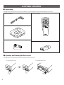 6
6
-
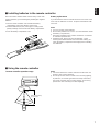 7
7
-
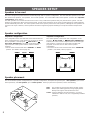 8
8
-
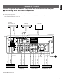 9
9
-
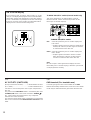 10
10
-
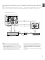 11
11
-
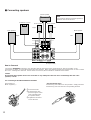 12
12
-
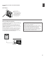 13
13
-
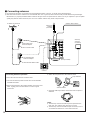 14
14
-
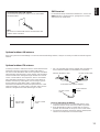 15
15
-
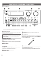 16
16
-
 17
17
-
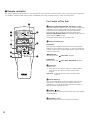 18
18
-
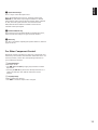 19
19
-
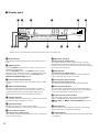 20
20
-
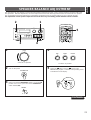 21
21
-
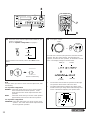 22
22
-
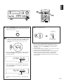 23
23
-
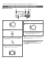 24
24
-
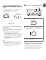 25
25
-
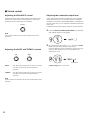 26
26
-
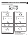 27
27
-
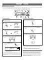 28
28
-
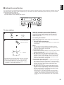 29
29
-
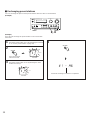 30
30
-
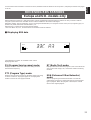 31
31
-
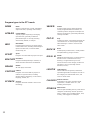 32
32
-
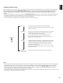 33
33
-
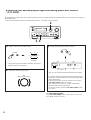 34
34
-
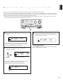 35
35
-
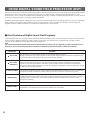 36
36
-
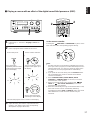 37
37
-
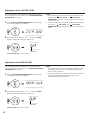 38
38
-
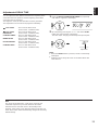 39
39
-
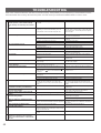 40
40
-
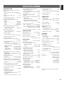 41
41
-
 42
42


Yamaha RX-V10MKII El manual del propietario
- Categoría
- Receptor
- Tipo
- El manual del propietario
en otros idiomas
- français: Yamaha RX-V10MKII Le manuel du propriétaire
- italiano: Yamaha RX-V10MKII Manuale del proprietario
- English: Yamaha RX-V10MKII Owner's manual
- Deutsch: Yamaha RX-V10MKII Bedienungsanleitung
- русский: Yamaha RX-V10MKII Инструкция по применению
- Nederlands: Yamaha RX-V10MKII de handleiding
- português: Yamaha RX-V10MKII Manual do proprietário
- dansk: Yamaha RX-V10MKII Brugervejledning
- polski: Yamaha RX-V10MKII Instrukcja obsługi
- čeština: Yamaha RX-V10MKII Návod k obsluze
- svenska: Yamaha RX-V10MKII Bruksanvisning
- Türkçe: Yamaha RX-V10MKII El kitabı
- suomi: Yamaha RX-V10MKII Omistajan opas
- română: Yamaha RX-V10MKII Manualul proprietarului
Artículos relacionados
-
Yamaha TX-10MKII El manual del propietario
-
-
-
Yamaha T-S1000 El manual del propietario
-
-
-
-
-
-