Yamaha RX-V371 Guia de referencia
- Categoría
- Receptores AV
- Tipo
- Guia de referencia
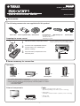
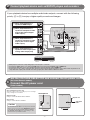
El Yamaha RX-V371 es un receptor de A/V de 5.1 canales con una variedad de características que pueden mejorar tu experiencia de entretenimiento en casa. Con soporte para HDMI, video compuesto y entradas de audio digital y analógico, puedes conectar fácilmente tus dispositivos de audio y video. El receptor también cuenta con un sintonizador de radio AM/FM incorporado, para que puedas escuchar tus emisoras favoritas. Además, con la función YPAO, puedes calibrar automáticamente los altavoces para una experiencia de sonido envolvente óptima.
El Yamaha RX-V371 es un receptor de A/V de 5.1 canales con una variedad de características que pueden mejorar tu experiencia de entretenimiento en casa. Con soporte para HDMI, video compuesto y entradas de audio digital y analógico, puedes conectar fácilmente tus dispositivos de audio y video. El receptor también cuenta con un sintonizador de radio AM/FM incorporado, para que puedas escuchar tus emisoras favoritas. Además, con la función YPAO, puedes calibrar automáticamente los altavoces para una experiencia de sonido envolvente óptima.


-
 1
1
-
 2
2
-
 3
3
-
 4
4
-
 5
5
-
 6
6
-
 7
7
-
 8
8


Yamaha RX-V371 Guia de referencia
- Categoría
- Receptores AV
- Tipo
- Guia de referencia
El Yamaha RX-V371 es un receptor de A/V de 5.1 canales con una variedad de características que pueden mejorar tu experiencia de entretenimiento en casa. Con soporte para HDMI, video compuesto y entradas de audio digital y analógico, puedes conectar fácilmente tus dispositivos de audio y video. El receptor también cuenta con un sintonizador de radio AM/FM incorporado, para que puedas escuchar tus emisoras favoritas. Además, con la función YPAO, puedes calibrar automáticamente los altavoces para una experiencia de sonido envolvente óptima.
en otros idiomas
- English: Yamaha RX-V371 Reference guide