
Dimmer
For the Compatible Bulb Tool...
Helpful videos...
Advanced programming & operation...
Additional wiring scenarios...
Replacing a dimmer with a dimmer...
If using LED or CFL bulbs, they
must be Lutron compatible!
Use www.lutron.com/ledfinder
to check compatibility.
P/N 0301930
Rev. A
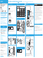
Sunnata touch dimmer
LED+ technology
LFCA
CFL
AFC
150 W
LED / LFCA
600 W
Incand. /Hal.
Help
Limited Warranty:
www.lutron.com/TechnicalDocumentLibrary/
369-119_Wallbox_Warranty.pdf
©2019 Lutron Electronics Co., Inc.
)Lutron, Lutron, Claro, LED+, and Sunnata are trademarks or
registered trademarks of Lutron Electronics Co., Inc., in the U.S.
and/or other countries.
www.lutron.com/SunnataSupport
www.lutron.com/SunnataSupport
IMPORTANT
1. CAUTION: Use only with permanently installed fixtures with dimmable
screw-in LED, dimmable screw-in compact fluorescent, halogen, or
incandescent lamps. To avoid overheating and possible damage to other
equipment, do not use to control receptacles, motor-driven appliances,
or low-voltage transformer-supplied appliances.
2. Install in accordance with all national and local electrical codes.
3. When no “grounding means” exists in wallbox, the 2011 National
Electrical CodeR (NECR) allows a control to be installed as a replacement
if 1) a nonmetallic, noncombustible faceplate is used with non-metallic
attachment screws or 2) the circuit is protected by a ground fault circuit
interrupter (GFCI). When installing a control according to these methods,
cap or remove green wire before screwing control into wallbox and use
an appropriate faceplate such as Claro series wallplates by Lutron.
4. 3-way wiring must use only one Sunnata Dimmer and an existing
mechanical switch. Re-wiring the mechanical switch is required. Product
is not compatible with 4-way wiring.
5. Never connect more than one dimmer to a load.
6. For indoor use only between 32 °F and 104 °F (0 °C and 40 °C).
7. Dimmer may feel warm to the touch during normal operation.
8. Clean dimmers with a soft damp cloth only. Do not use any
chemical cleaners.
SUNNATA
FCC Supplier Declaration of Conformity / IC:
This device complies with part 15 of the FCC Rules.
Operation is subject to the following two conditions:
(1) This device may not cause interference, and
(2) this device must accept any interference, including
interference that may cause undesired operation.
CAN ICES-5 (B)/NMB-5(B)
Advanced Programming Options
These advanced programming options can be changed for your dimmer:
1. Adjust the high-end light output
2. Turn the light bar Off during Idle and Nightlight states
3. Adjust the light bar brightness higher or lower
4. Change the Preset Light Level or Unlock the Preset to recall previous level
See the Sunnata Advanced Programming Mode Application Note #734
(P/N 048734) at www.lutron.com/SunnataSupport for details on how to
change these settings.
For Troubleshooting see reverse side
STCL-153P
120 V~ 60 Hz
Use our mobile friendly self-paced
installation tool:
www.lutron.com/wiringwizard
Find more product information:
www.lutron.com/support
- Videos
- Frequently Asked Questions
Call us:
U.S.A. | Canada | Caribbean
1.844.LUTRON1 (588.7661) (24/7)
Mexico
+1.888.235.2910
Others
+1.610.282.3800
F
A
S
S
•
F
A
S
S
•
F
A
S
S
•
F
A
S
S
•
F
A
S
S
•
F
A
S
S
•
OFF
ON
WARNING: ELECTRIC SHOCK HAZARD.
May Result in Serious Injury or Death.
Disconnect power before servicing or installing.
1
Determine wiring type
2
Turn power OFF at circuit breaker
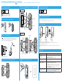
5
Connect the new dimmer
6
Mount dimmer using the provided screws
7
Turn power ON at circuit breaker
8
Operation
9
Set low-end trim
3
Remove existing device
Disconnect wires.
4
Check ratings
a. For lights controlled from one location (single-pole):
Proceed to step 2 below.
On
On
Off
Off
MAXIMUM RATINGS FOR MIXED LOAD TYPES
0 W + 600 W 500 W 400 W
1 W – 25 W + 500 W 400 W 300 W
26 W – 50 W + 400 W 300 W 200 W
51 W – 75 W + 300 W 200 W 100 W
76 W – 100 W + 200 W 100 W 50 W
101 W – 125 W + 100 W 50 W 0 W
126 W – 150 W + 0 W 0 W 0 W
(Front Accesible Service Switch)
Pull tab out for bulb replacement.
LFCA
CFL
AFC
CFL
+
Low-End Trim:
1. Touch the middle of light bar
continually for about
6 seconds. (Do not depress
the OFF button).
2. Slide finger on light bar to
adjust to desired brightness.
3. To exit, press the OFF
button.
Black
Blue
Black
Green
(ground)
b. For lights controlled from two locations (3-way), see reverse side:
Rewiring in both locations is required.
c. 3 or more locations:
Product is not compatible.
See www.lutron.com/dimmers for options.
For videos and step by step instructions, please see
www.lutron.com/wiringwizard
FASS Switch
W1
W1
W2
W2
Adjust:
(Light Bar)
• Touch the light bar to set
the lamps to desired level.
• Slide to adjust the
light level.
NOTE: For advanced programming options see the Sunnata
Advanced Programming Mode Application Note #734 (P/N 048734)
at www.lutron.com/SunnataSupport
Single gang End of gang Middle of gang
OPTIONAL FOR INCANDESCENT / HALOGEN
Incadescent / Halogen
LED I/H
LED I/H
LED I/H
LED I/H
LED
For lights controlled from one location
(For lights controlled from two locations, see instructions on reverse)
Ground wire
(green or bare copper)

OFF
ON
WARNING: ELECTRIC SHOCK HAZARD.
May result in Serious Injury or Death. Turn off
power at circuit breaker or fuse before installing.
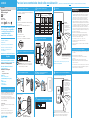
1
Turn power OFF at circuit breaker
5
Connect the new MASTER dimmer and re-wire OTHER EXISTING switch
6
Mount all devices using the provided screws
Troubleshooting
7
Turn power ON at circuit breaker
2
Remove (but do not disconnect) existing devices
3
Mark wire on the COMMON terminal
See step 9, “Set Low-End Trim” on reverse side for details of setting the low-end trim.
1. Triple tap the OFF button rapidly holding on the last press.
2. Continue holding until the light bar and the lighting load begin to raise from low to high in about 3 seconds.
3. Immediately triple tap the OFF button again.
4. The light bar and lighting load will begin to raise from low to high 3 times, the lights turn off, and then turn back on to
high-end.
4
Disconnect wires from the switch at the dimmer location
On both existing devices, mark the wire (for example, using electrical tape) that is connected
to the screw that is a different color (typically black) than all the others. The different
color screw may be on either side of the switch. This screw terminal may also be labeled
“COMMON” or “COM”. Does not include the ground screw.
Rear / side view of existing device
8
Adjust dimming range for LEDs and CFLs
Restoring Default Settings
OPTIONAL FOR INCANDESCENT / HALOGEN
+
COM
Symptom Probable Cause and Action
LEDs or CFLs do not dim, have
a poor dimming range, or they
flicker / flash
1. Verify light bar and switch operation, see Step 8 on reverse side
2. To confirm that the bulbs are Lutron compatible, see our LED compatibility
tool at www.lutron.com/LEDfinder
3. Adjust the low-end trim, see Step 9 on reverse side
Audible buzzing
(common with LEDs)
To confirm that the bulbs are Lutron compatible, see our LED compatibility tool
at www.lutron.com/LEDfinder
Dimmer does not turn on
(light bar not illuminated)
1. Check breaker
2. Check that the bulb is installed and has not failed
3. For 3-way:
a. Check the wiring of the dimmer in Location 1. See step 5 on this side
b. Did you re-wire the switch in Location 2? See step 5 on this side for
Location 2 re-wiring
4. Check that the FASS airgap switch is pushed in
Indicator LEDs of the light bar are
too bright or too dim
Change the intensity of the Indicator LEDs using the Advanced Programming
feature. Please see the Sunnata Advanced Programming Mode Application Note
#734 (P/N 048734) at www.lutron.com/SunnataSupport
For additional troubleshooting, please visit www.lutron.com/SunnataSupport
.
W2
W1
.
.
Non-black wire
Different
color
screw
Tagged
wire
Tagged wire
Yellow jumper wire
Before After
Ground wire
(green or bare copper)
W1
W1
W2
W2
.
Location 1
Location 2
Black
Tagged wire
Non-black wire
Blue
Black
Green
(ground)
W1
W2
Different
color screw
3 sec
Off Off Off
For lights controlled from two locations
(Dimmer not compatible with lights controlled from three or more locations)

Ayuda
www.lutron.com/SunnataSupport
SUNNATA
Utilice nuestra amigable herramienta
móvil de instalación a su propio ritmo:
www.lutron.com/wiringwizard
Encuentre información adicional
sobre el producto:
www.lutron.com/support
- Videos
- Preguntas frecuentes
Llámenos:
E.U.A. | Canadá | Caribe
1.844.LUTRON1 (588.7661) (24/7)
México
+1.888.235.2910
Demás países
+1.610.282.3800
F
A
S
S
•
F
A
S
S
•
F
A
S
S
•
F
A
S
S
•
F
A
S
S
•
F
A
S
S
•
OFF
ON
ADVERTENCIA: PELIGRO DE DESCARGA
ELÉCTRICA. Podría ocasionar lesiones graves o la
muerte. Antes de instalar desconecte la alimentación
eléctrica en el disyuntor o el fusible.
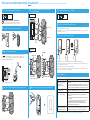
1
Determine el tipo de cableado
2
Desconecte el suministro eléctrico en el disyuntor
5
Conecte el nuevo atenuador
6
Monte el atenuador utilizando los
tornillos suministrados
7
CONECTE el suministro eléctrico en el disyuntor
8
Operación
3
Retire el dispositivo existente
Desconecte los cables.
On
On
Off
Off
+
W1
W2
OPCIONAL PARA INCANDESCENTE / HALÓGENA
Atenuador
Para obtener la herramienta de
bombillas compatibles...
Videos útiles...
Programación y operación avanzadas...
Escenarios de cableado adicionales...
Reemplazo de un atenuador con
otro atenuador...
¡Si se utilizan bombillas LED o
LFCA, deben ser compatibles
con Lutron! Para verificar la
compatibilidad utilice
www.lutron.com/ledfinder
N/P 0301930
Rev. A
Atenuador táctil Sunnata
LED+ tecnología
LFCA
CFL
AFC
150 W
LED / LFCA
600 W
Incand. / Hal.
www.lutron.com/SunnataSupport
STCL-153P
120 V~ 60 Hz
LED I/H
LED I/H
Garantía limitada:
www.lutron.com/TechnicalDocumentLibrary/369-119_Wallbox_
Warranty.pdf
©2019 Lutron Electronics Co., Inc.
)Lutron, Lutron, Claro, LED+ y Sunnata son marcas
comerciales o marcas comerciales registradas de Lutron
Electronics Co., Inc. en E.U.A. y/o en otros países.
Declaración de conformidad del proveedor con la FCC/IC:
Este dispositivo satisface la Parte 15 de las reglas de la FCC.
La operación está sujeta a las dos siguientes condiciones:
(1) Este dispositivo no debe causar interferencias y
(2) este dispositivo debe aceptar cualquier interferencia, incluida
la interferencia que pudiera ocasionar una operación no deseada.
CAN ICES-5 (B)/NMB-5(B)
Para las luces controladas desde sólo una ubicación
(Para las luces controladas desde dos ubicaciones, consulte las instrucciones al dorso)
a. Para las luces controladas desde una ubicación (unipolares):
Prosiga al paso 2 más abajo.
b. Para las luces controladas desde dos ubicaciones (tres vías)
consulte el reverso:
Se requiere volver a cablear en ambas ubicaciones.
c. Tres o más ubicaciones:
El producto no es compatible.
Para opciones consulte www.lutron.com/dimmers
Negro
Azul
Negro
Verde
(tierra)
W1
W2
4
Consulte las especificaciones
ESPECIFICACIONES MÁXIMAS PARA TIPOS DE CARGA MIXTA
0 W + 600 W 500 W 400 W
1 W – 25 W + 500 W 400 W 300 W
26 W – 50 W + 400 W 300 W 200 W
51 W – 75 W + 300 W 200 W 100 W
76 W – 100 W + 200 W 100 W 50 W
101 W – 125 W + 100 W 50 W 0 W
126 W – 150 W + 0 W 0 W 0 W
LFCA
CFL
AFC
LFCA
Grupo indiv. Final del grupo
Punto medio
del grupo
Incandescente / Halógena
LED I/H
LED I/H
LED
Ajuste:
(Barra de luces)
• Toque la barra de luces
para configurar las
lámparas al nivel deseado.
• Deslice para ajustar el
nivel de luz.
(Interruptor de servicio de acceso
frontal) Para el reemplazo de la bombilla
tire de la lengüeta hacia afuera.
Para obtener videos e instrucciones paso a paso, visite
www.lutron.com/wiringwizard
Interruptor FASS
9
Configure el ajuste de la intensidad mínima
Ajuste de la
intensidad mínima:
1. Pulse continuamente el
centro de la barra de luces
durante alrededor de seis
segundos. (No oprima el
botón de APAGADO).
2. Deslice el dedo sobre la
barra luminosa para ajustar
al brillo deseado.
3. Para salir, pulse el botón
de APAGADO.
NOTA: Para obtener opciones avanzadas de programación consulte
la Nota de aplicación Nº 734 (N/P 048734) de Sunnata Modo de
programación avanzado en www.lutron.com/SunnataSupport
IMPORTANTE
1. PRECAUCIÓN: Sólo utilizar con artefactos instalados permanentemente
con LED atenuables de tipo atornillable, lámparas fluorescentes compactas
y atenuables, halógenas o incandescentes. Para evitar el recalentamiento
y posibles daños a otros equipos, no utilizar para controlar receptáculos,
artefactos accionados a motor o aparatos provistos de transformador.
2. Instale de acuerdo con todas las normativas eléctricas nacionales y locales.
3. Cuando no existan “medios de conexión a tierra” en la caja de empotrar, el
Código Eléctrico Nacional 2011R (NECR) permite que un control sea instalado
como reemplazo si 1) se utiliza una placa frontal no metálica y no combustible
con tornillos de fijación no metálicos o 2) el circuito está protegido por un
disyuntor de falla de tierra (GFCI). Cuando instale un control de acuerdo con
estos métodos, cubra o retire el cable verde antes de atornillar el control a la
caja de empotrar, y utilice una placa frontal adecuada tal como las placas de
pared de las series Claro de Lutron.
4. El cableado de tres vías debe utilizar sólo un atenuador Sunnata y un
interruptor mecánico existente. Se requiere volver a cablear el interruptor
mecánico. El producto no es compatible con el cableado de cuatro vías.
5. Nunca conecte más de un atenuador a una carga.
6. Sólo para uso bajo techo entre 0 °C y 40 °C (32 °F y 104 °F).
7. Los atenuadores pueden sentirse calientes al tacto durante el
funcionamiento normal.
8. Sólo limpie los atenuadores con un paño suave y húmedo. No utilice ningún
limpiador químico.
Opciones de programación avanzada
Estas opciones de programación avanzadas pueden ser cambiadas para
su atenuador:
1. Ajuste la salida de luz de intensidad máxima
2. Desactive la barra de luces durante los estados de inactividad y
luz nocturna
3. Ajuste el brillo de la barra de luces hacia arriba o hacia abajo
4. Cambie el nivel de luz preestablecido o desbloquee el preajuste para
recuperar el nivel anterior
Para obtener detalles sobre cómo cambiar estos ajustes consulte la Nota
de aplicación Nº 734 (N/P 048734) de Sunnata Modo de programación
avanzada en www.lutron.com/SunnataSupport.
Para la solución de problemas, consulte en el reverso
Cable de Tierra
(verde o de cobre pelado)

OFF
ON
ADVERTENCIA: PELIGRO DE DESCARGA ELÉCTRICA.
Podría ocasionar lesiones graves o la muerte. Antes de instalar
desconecte la alimentación eléctrica en el disyuntor o el fusible.
1
Desconecte el suministro eléctrico en el disyuntor
5
Conecte el atenuador PRINCIPAL nuevo y recablear el OTRO
interruptor EXISTENTE
6
Monte todos los dispositivos utilizando los tornillos suministrados
7
CONECTE el suministro eléctrico en el disyuntor
2
Retire (pero no desconecte) los dispositivos existentes
3
Marque el cable del terminal COMÚN
En ambos dispositivos existentes marque el cable (por ejemplo, utilizando cinta aisladora)
que está conectado al tornillo que es de color diferente (generalmente negro) que todos
los demás. Este terminal atornillable puede también rotularse como “COMÚN” o “COM”.
No incluye el tornillo de puesta a tierra.
Vista trasera/lateral del dispositivo existente
8
Ajuste el rango de atenuación de los LED y los LFCA
OPCIONAL PARA INCANDESCENTE / HALÓGENA
+
COM
3 seg
Off Off Off
Para las luces controladas desde dos ubicación
(El atenuador no es compatible con las luces controladas desde tres o más ubicaciones)
4
Desconecte los cables del interruptor en la ubicación del atenuador
.
W2
W1
Tornillo de
color
diferente
.
.
Cable no negro
Tornillo
de color
diferente
Cable
rotulado
Cable rotulado
Cable de puente amarillo
Antes Después
Cable de Tierra
(verde o de cobre pelado)
W1
W1
W2
W2
.
Ubicación 1
Ubicación 2
Negro
Cable rotulado
Cable no negro
Azul
Negro
Verde
(tierra)
W1
W2
Para obtener detalles sobre cómo configurar el ajuste de la intensidad mínima consulte el paso 9, “Configure el ajuste de la
intensidad mínima”, en el reverso.
1. Pulse rápidamente tres veces el botón de APAGADO manteniéndolo presionado en la última pulsación.
2. Continúe manteniendo pulsado hasta que la barra de luces y la carga de iluminación comiencen a aumentar desde bajo
a alto en aproximadamente tres segundos.
3. Pulse inmediatamente tres veces de nuevo el botón de APAGADO.
4. La barra de luces y la carga de iluminación comenzarán a aumentar desde bajo a alto tres veces, las luces se apagarán,
y luego se encenderán nuevamente a su intensidad máxima.
Restauración de los parámetros predeterminados
Solución de problemas
Síntoma Causa probable y acción
Los LED o las LFCA no se
atenúan, tienen un rango de
atenuación escaso o
parpadean / destellan
1. Verique la operación de la barra de luces y del interruptor; consulte el paso 8
en el reverso
2. Para conrmar que las bombillas sean compatibles con Lutron, consulte
nuestra herramienta de compatibilidad con LED en www.lutron.com/LEDnder
3. Congure el ajuste de la intensidad mínima; consulte el paso 9 en el reverso
Zumbido audible
(común con los LED)
Para conrmar que las bombillas sean compatibles con Lutron, consulte nuestra
herramienta de compatibilidad con LED en www.lutron.com/LEDnder
El atenuador no se activa
(la barra de luz no se ilumina)
1. Verique disyuntor
2. Verique que la bombilla esté instalada y no haya quedado defectuosa
3. Para tres vías:
a. Verique el cableado del atenuador en la Ubicación 1. Consulte el paso 5
en este lado
b. ¿Se recableó el interruptor en la Ubicación 2? Para informarse sobre el
recableado en la Ubicación 2 consulte el paso 5 en este lado
4. Verique que el interruptor de espacio de aire del FASS (Interruptor de
Servicio de Acceso Frontal) esté empujado
Los LED indicadores de la barra
de luces se iluminan demasiado
brillantes o demasiado tenues
Cambie la intensidad de los LED indicadores con la funcionalidad Programación
avanzada. Consulte la Nota de aplicación Nº 734 (N/P 048734) de Sunnata
Modo de programación avanzado en www.lutron.com/SunnataSupport
Para obtener soluciones adicionales de problemas, visite www.lutron.com/SunnataSupport
-
 1
1
-
 2
2
-
 3
3
-
 4
4


Lutron STCL-153PH-LA Guía de instalación
- Tipo
- Guía de instalación
- Este manual también es adecuado para
en otros idiomas
Artículos relacionados
-
Lutron MACL-LFQH-WH Guía de instalación
-
Lutron CTCL-153PDH-WH Manual de usuario
-
-
-
-
Lutron MSCL-OP153M-MS Guía de instalación
-
-
-
-
Lutron DVSCFSQ-LF-TP Guía de instalación