Schulte FX-742 El manual del propietario
- Categoría
- Cortadoras de césped
- Tipo
- El manual del propietario

©2021 Alamo Group Inc.
Published 07/21 S/N C74220135108-C74220142108 Part No. C742-010C
OPERATOR’S MANUAL
This Operator's Manual is an
integral part of the safe operation
of this machine and must be
maintained with the unit at all
times. READ, UNDERSTAND, and
FOLLOW the Safety and
Operation Instructions contained
in this manual before operating
the equipment. C01-Cover_S
Important Operating
and Safety
Instructions are found
in the Mower Safety
Video that can be
instantly accessed on
the internet at:
www.algqr.com/sve
$0.00
FX-742
Rotary Cutter
Schulte Industries Ltd.
PO Box 70
Englefeld Saskatchewan
Canada S0K 1N0
Tel. (306) 287-3715
Fax. (306) 287-3355
Parts Fax. (306) 287-4066
Web: www.schulte.ca


In order to reduce accidents and enhance the safe operation of mowers, Schulte, in cooperation with other industry
manufacturers has developed the AEM/FEMA Industrial and Agricultural Mower Safety Practices video and guide
book.
The video will familiarize and instruct mower-tractor operators in safe practices when using industrial and
agricultural mowing equipment. It is important that Every Mower Operator be educated in the operation of their
mowing equipment and be able to recognize the potential hazards that can occur while operating a mower. This
video, along with the mower operator’s manual and the warning messages on the mower, will significantly assist in
this important education.
Your Authorized Schulte Dealer may have shown this video and presented you a DVD Video when you purchased
your mower. If you or any mower operator have not seen this video, Watch the Video, Read this Operator’s
Manual, and Complete the Video Guidebook before operating your new mower. If you do not understand any of
the instructions included in the video or operator’s manual or if you have any questions concerning safety of
operation, contact your supervisor, dealer or Schulte.
If you would like a VHS video tape of the video, please e-mail [email protected] or Fax AEM VHS
Video at (830) 372-9529 or mail in a completed copy of the form on the back of this page to AEM VHS Video 1502
E Walnut Street, Seguin, TX 78155. and request the VHS video version. Please include your name, mailing
address, mower model and serial number.
Every operator should be trained for each price of equipment (Tractor and Mower), Understand the intended use,
and the potential hazards before operating the equipment.
The information and material listed above along with this Operator’s Manual can assist you in meeting the OSHA
requirement for Operator annual training.
OSHA TRAINING REQUIREMENTS
The following training requirements have been taken from Title 29, Code of Federal Regulations Part
1928.57 (a)(6). www.osha.gov
Operator Instructions. At the time of initial assignment and at least annually thereafter, the employer shall instruct
every employee who operates an agricultural tractor or implement in the safe operating practices and servicing of
equipment with which they are or will be involved, and of any other practices dictated by the work environment.

Schulte Industries LTD. is willing to provide
one (1) AEM Mower Safety Practices Video
Please Send Me: VHS Format – AEM/FEMA Mower Operator Safety Video
DVD Format – AEM/FEMA Mower Operator Safety Video
Mower Operator’s Manual
AEM Mower Operator’s Safety Manual
Requester Name:_____________________________Phone:_____________________________
Requester Address:_________________________________________
City:____________________________________
State:___________________________________
Zip Code: _______________________________
Mower Model:_________________________Serial Number:________________________
Date Purchased:_______________________Dealer Salesperson:____________________
Dealership Name:______________________Dealership Location:____________________
Mail to:
AEM Video Services
1502 E. Walnut Street
Seguin, TX 78155
Or Fax to:
(830) 372-9529
Or E-mail to:
AEMVideo@alamo-group.com

To the Owner/Operator/Dealer
This Operator's Manual is an integral part of the safe operation of this machine and must be maintained with the
implement at all times. A Manual canister is provided on the implement where this manual can be properly stored.
If you lose or damage this manual a free replacement manual can be obtained from an authorized Schulte dealer or
by down loading the manual from the Schulte website www.schulte.ca
BEFORE YOU START! READ, UNDERSTAND, and FOLLOW the information provided in this manual, the AEM
Mower Safety manual and the tractor operator's manual carefully to learn how to operate and service your machine
properly. Failure to do so could result in personal injury to you and bystanders. All implements with moving parts
are potentially hazardous. Every effort has been made to ensure that the machine is safe but operators must avoid
engaging in unsafe practices and follow the written instructions provided. The manufacturer has designed this
implement to be used with all its safety equipment properly attached to minimize the chance of accidents.
SAFETY FIRST. Completely read and understand the safety section of this manual before operating this
equipment. Do not allow anyone to operate this equipment who has not fully read and understood this manual.
Contact your Dealer to explain any instructions that you do not fully understand.
The care you give your Schulte Implement will greatly determine your satisfaction with its performance and its
service life. Carefully read and follow the instructions in this manual to provide you with a thorough understanding
of your new implement and its intended use and service requirements.
All references made in this manual to right, left, front, rear, top or bottom are as viewed facing the direction of
forward travel with the implement properly attached to the tractor.
Replacement Parts information is located in a separate Parts Manual. Schulte mowers use balanced and matched
system components for blade carriers, blades, cuttershafts, knives, knife hangers, rollers, drivetrain components,
and bearings. These parts are made and tested to Schulte specifications. Non-genuine “will fit” parts do not
consistently meet these specifications. The use of “will fit” parts may reduce mower performance, void warranties,
and present a safety hazard. Use genuine Schulte mower parts for economy and safety.
For future reference, record your Schulte product model number and serial number.
Dealer Telephone Model Number
Owner Purchase Date: Serial Number
SERIAL NUMBER PLATE

DEALER to CUSTOMER Pre-Delivery/ Operation Instructions
Dealer should inform the Purchaser of this product of Warranty terms, provisions, and procedures that are
applicable. Dealer should inform Purchaser to review the contents of the Operator’s Manual including safety
equipment, safe operation and maintenance, to review the Safety Signs on the implement (and tractor if possible)
and of Purchaser’s responsibility to train his/her operators’s of safe operation procedures.
•IMPLEMENTS: I have explained that Deflectors, Chain Guards, or Solid Skirts must be installed and
maintained in good repair.
•DRIVELINES: I have made certain that all driveline, gearbox, and other shields are in good repair and
fastened securely in place to prevent injuries from entanglement or thrown objects.
•HYDRAULIC MACHINES: I have explained the necessity of using clean hydraulic oil, changing filters as
instructed, stopping leaks, damage caused by operating with over-heated oil, caring for hoses, using hoses of
proper rating, maintaining the specified operating pressure and the potential hazard of oils penetrating the
skin.
•FOLDING-TYPE IMPLEMENTS: I have explained that it is not possible to guard against thrown objects when
the head is lifted off ground and that operator is responsible to watch out for persons in the area. I have
explained that the lifted mower head or boom can contact overhead obstructions with damage to cables and
telephone lines and possible injury. I have explained that the extended head or boom or retracted boom can
contact power lines resulting in electrocution, injury or death and that operator is responsible for keeping clear
of such hazards.
PRE-DELIVERY SERVICE
CHECK AND ADJUST OR LUBRICATE AS REQUIRED
See Operator’s Manual for Details
Inspection Performed - Warranty and Safety Procedures Explained - Installation Complete
LUBRICATION & HYDRAULICS
Gearbox (Oil Levels)
Hydraulic Oil Level (External Tank)
Tractor Hydraulic Oil Level
Hydraulic Hoses (Not Kinked Tighten Connections)
Front Pump Drive (Assembly Is Tight And Shaft Properly
Aligned)
MOWER
Spindle And Motor Bolts Properly Torqued
Spindle Oil Level
Blade Carrier Bolts Properly Torqued/Retaining Pin In
Place
Mower Cutting Height And Level Adjusted
Cutting Shaft Bearings Lubricated
All Hardware Properly Torqued
Tire and Air Pressure/Lug Nuts (Correct Torque)
Wheel Bearings (Check, Grease, and Preload)
ATTACHMENTS & INSTALLATION
Deflectors Front And Rear
Shredding Attachments
Correct Blade Rotation Direction
Axle Arms And Beams
Tongue And Control Rods (Installed And Adjusted)
All Bolts - Pins And Nuts (Proper Torque)
MOWER TO TRACTOR CONNECTIONS
Draw Bar Length (Check And Set)
A-Frame Pivot & Links
Control Rods (Adjusted Equal)
Axle Height (Adjusted)
Cutting Height (Adjust)
Mount Kit-Pre-Operation Check Complete
Mower Wing (Adjust Level With The Center)
Mower Wing (Check For Proper Raising Operation)
C.V. Drivelines (Check Max Turn Radius)
Pull Type Hitch (Height Adjustment)
Mounting Hardware Properly Torqued
SAFETY ITEMS
Protective Shields (Operation And Installation)
Driveline Clutch (Torque Limiter) (Adjust And Run In)
Safety Decals (Installed)
Operator’s Manual (Supplied)
Tractor PTO Shield (Installed)
S.M.V. Emblem (Installed If Needed)
Tongue Jack (Installation and Operation)
Safety Tow Chain (Installed)
ADMA Driveline Safety Manual Supplied
AEM Mower Safety Manual (Supplied in Canister)
AEM Mower Safety Video has been shown to Purchaser

Table of Contents
SAFETY SECTION .............................................................................................................. 1-1
GENERAL SAFETY INSTRUCTIONS AND PRACTICES .................................................................................1-2
OPERATOR SAFETY ........................................................................................................................................1-3
CRUSHING HAZARDS ......................................................................................................................................1-4
CONNECTING OR DISCONNECTING IMPLEMENT SAFETY ........................................................................1-5
THROWN OBJECTS HAZARDS .......................................................................................................................1-6
RUN OVER HAZARDS ......................................................................................................................................1-8
PTO ENTANGLEMENT HAZARDS ...................................................................................................................1-9
MOWER BLADE CONTACT HAZARDS ..........................................................................................................1-10
HIGH PRESSURE OIL LEAK HAZARD ...........................................................................................................1-11
ELECTRICAL & FIRE HAZARDS ....................................................................................................................1-12
TRANSPORTING HAZARDS ..........................................................................................................................1-13
HAZARDS WITH MAINTENANCE OF IMPLEMENT .......................................................................................1-14
HAZARDS WITH MAINTENANCE OF IMPLEMENT - (CONTINUED) ............................................................1-15
Storage and Parking Safety Instructions and Practices ...................................................................................1-16
Concluding Safety Instructions and Practices ..................................................................................................1-16
DECAL LOCATION ..........................................................................................................................................1-17
DECAL DESCRIPTION ...................................................................................................................................1-19
FEDERAL LAWS AND REGULATIONS ..........................................................................................................1-28
INTRODUCTION SECTION ................................................................................................. 2-1
Equipment Specifications ...................................................................................................................................2-3
KEY OPERATION POINTS ...............................................................................................................................2-4
Operating Noise Level/Sound Pressure .............................................................................................................2-4
ASSEMBLY SECTION ........................................................................................................ 3-1
GENERAL .......................................................................................................................................................... 3-2
CHAIN GUARDS ...............................................................................................................................................3-2
HYDRAULIC CIRCUITS ....................................................................................................................................3-3
Wing System ......................................................................................................................................................3-3
Phasing System .................................................................................................................................................3-4
TRANSPORT LIGHTS .......................................................................................................................................3-5
Installation of Lights ...........................................................................................................................................3-5
Wiring of Lights ..................................................................................................................................................3-6
DRIVELINE SHIELD ..........................................................................................................................................3-7
GEARBOX LAYOUT & BLADE ROTATION ...................................................................................................... 3-7
Row Crop Wheel Standard Spacing ..................................................................................................................3-9
OPERATION SECTION ....................................................................................................... 4-1
OPERATOR REQUIREMENTS .........................................................................................................................4-3
TRACTOR REQUIREMENTS ............................................................................................................................4-4
ROPS and Seat Belt ..........................................................................................................................................4-4
Tractor Safety Devices .......................................................................................................................................4-4
Tractor Horsepower ...........................................................................................................................................4-5
Drawbar .............................................................................................................................................................4-5
Tractor Hydraulics .............................................................................................................................................. 4-5
Front End Weight ..............................................................................................................................................4-5
Power Take Off (PTO) ....................................................................................................................................... 4-5

Tire Spacing .......................................................................................................................................................4-6
GETTING ON AND OFF THE TRACTOR .........................................................................................................4-6
Boarding the Tractor ..........................................................................................................................................4-7
Dismounting the Tractor ....................................................................................................................................4-7
STARTING THE TRACTOR ..............................................................................................................................4-8
CONNECTING THE MOWER TO THE TRACTOR ...........................................................................................4-8
Connecting the Mower Tongue to the Tractor ...................................................................................................4-9
Safety Tow Chain ..............................................................................................................................................4-9
Connecting Implement Hydraulic Lines to the Tractor .....................................................................................4-10
Taking the Cutter Out of Transport .................................................................................................................. 4-11
SETTING THE MOWER ..................................................................................................................................4-12
Setting Deck Height .........................................................................................................................................4-12
Setting Deck Pitch ............................................................................................................................................4-13
Leveling Wing ..................................................................................................................................................4-13
Adjusting Counter Pressure Valve ...................................................................................................................4-14
Adjusting Lift Rods ...........................................................................................................................................4-15
DRIVELINE ATTACHMENT ............................................................................................................................4-16
Driveline Length Check ....................................................................................................................................4-16
Constant Velocity (CV) Driveline ......................................................................................................................4-18
PRE-OPERATION INSPECTION AND SERVICE ...........................................................................................4-19
Tractor Pre-Operation Inspection/Service ........................................................................................................4-20
Mower Pre-Operation Inspection/Service ........................................................................................................4-20
Cutting Component Inspection .........................................................................................................................4-24
Blade Bolt Inspection .......................................................................................................................................4-26
DRIVING THE TRACTOR AND IMPLEMENT .................................................................................................4-29
Starting the Tractor ..........................................................................................................................................4-30
Brake and Differential Lock Setting ..................................................................................................................4-30
Operating the Cutter Wings .............................................................................................................................4-30
Crossing Ditches and Steep Inclines ...............................................................................................................4-31
OPERATING THE TRACTOR AND IMPLEMENT ...........................................................................................4-32
Foreign Debris Hazards ...................................................................................................................................4-33
Bystanders/Passersby Precautions .................................................................................................................4-33
Engaging the Power Take Off (PTO) ...............................................................................................................4-34
PTO RPM and Ground Speed .........................................................................................................................4-35
Operating the Mower .......................................................................................................................................4-35
Right of Way (Highway) Mowing ......................................................................................................................4-39
Shutting Down the Implement ..........................................................................................................................4-40
DISCONNECTING THE MOWER FROM THE TRACTOR .............................................................................4-40
MOWER STORAGE ........................................................................................................................................4-42
TRANSPORTING THE TRACTOR AND IMPLEMENT ...................................................................................4-43
Tires and Wheels .............................................................................................................................................4-44
Locking the Cutter For Transport .....................................................................................................................4-45
Transporting on Public Roadways ...................................................................................................................4-46
Hauling the Tractor and Implement ..................................................................................................................4-49
TROUBLESHOOTING GUIDE ........................................................................................................................4-50
MAINTENANCE SECTION .................................................................................................. 5-1
HAZARDS WITH MAINTENANCE OF IMPLEMENT .........................................................................................5-2
HAZARDS WITH MAINTENANCE OF IMPLEMENT - (CONTINUED) ..............................................................5-3
PARTS INFORMATION ..................................................................................................................................... 5-4
LUBRICATION ...................................................................................................................................................5-4
Grease Schedule ...............................................................................................................................................5-8
Tractor Shaft ......................................................................................................................................................5-9
Drivelines .........................................................................................................................................................5-10
Cutter Frame ....................................................................................................................................................5-10

Blade and Blade Carriers .................................................................................................................................5-11
Blade Installation ..............................................................................................................................................5-11
Blade Carrier Removal .....................................................................................................................................5-11
Blade Carrier Installation ..................................................................................................................................5-12
SLIP CLUTCHES .............................................................................................................................................5-13
Disassembly .....................................................................................................................................................5-13
Reassembly .....................................................................................................................................................5-14
HUBS & SPINDLES .........................................................................................................................................5-16
Greasing and Installation .................................................................................................................................5-16
Tightening Instructions for 517 & 511 Hubs .....................................................................................................5-17
Tires and Wheels .............................................................................................................................................5-17
HYDRAULIC HOSES .......................................................................................................................................5-18
STORAGE .......................................................................................................................................................5-20
PROPER TORQUE FOR FASTENERS ..........................................................................................................5-20
NUTS & BOLTS ...............................................................................................................................................5-21


Safety Section 1-1
© 2021 Alamo Group Inc.
SAFETY SECTION

SAFETY
FX-742 07/21 Safety Section 1-2
© 2021 Alamo Group Inc.
SAFETY
GENERAL SAFETY INSTRUCTIONS AND PRACTICES
A careful operator is the best operator. Safety is of primary importance to the manufacturer and should be to
the owner/operator. Most accidents can be avoided by being aware of your equipment, your surroundings,
and observing certain precautions. The first section of this manual includes a list of Safety Messages that, if
followed, will help protect the operator and bystanders from injury or death. Read and understand these
Safety Messages before assembling, operating or servicing this Implement. This equipment should only be
operated by those persons who have read the manual, who are responsible and trained, and who know how
to do so responsibly.
The Safety Alert Symbol combined with a Signal Word, as seen below, is used throughout this
manual and on decals which are attached to the equipment. The Safety Alert Symbol means:
“ATTENTION! BECOME ALERT! YOUR SAFETY IS INVOLVED!” The Symbol and Signal Word
are intended to warn the owner/operator of impending hazards and the degree of possible injury
faced when operating this equipment.
Practice all usual and customary safe working precautions and above all---remember safety is up to YOU.
Only YOU can prevent death or serious injury from unsafe practices.
Indicates a hazardous situation that, if not avoided, WILL result in DEATH OR VERY
SERIOUS INJURY.
Indicates a hazardous situation that, if not avoided, COULD result in DEATH OR
SERIOUS INJURY.
Indicates a hazardous situation that, if not avoided, MAY result in MINOR OR
MODERATE INJURY.
Indicates information considered important, but not hazard-related (e.g. messages
relating to property damage).
NOTE: Identifies points of particular interest for more efficient and convenient operation or repair.
READ, UNDERSTAND, and FOLLOW the following Safety Messages.
Death or serious injury may occur unless care is taken to follow the
warnings and instructions stated in this Manual and in the Safety
Messages on the implement. Always follow the instruction in this manual
and use good common sense to avoid hazards.
Pictographs are used throughout this manual to help bring your visual
attention to safety issues.
NOTE: If you want a translation of this safety section in one of the following Languages, please contact:
Translations at 1502 E. Walnut Street Seguin, TX 78155; Fax: (830) 372-9529; Safety Section Translations
are available in Spanish, Portuguese, French, German, Russian. PN GS-01

SAFETY
FX-742 07/21 Safety Section 1-3
© 2021 Alamo Group Inc.
SAFETY
OPERATOR SAFETY
TO AVOID DEATH OR SERIOUS INJURY DO THE FOLLOWING:
•READ, UNDERSTAND and FOLLOW Operator's Manual instructions, Warnings and Safety Messages.
•WEAR SAFETY GLASSES with side shields (marked with ANSI Z87), safety shoes, hard hat, hearing
protection and gloves when operating or repairing equipment
•WEAR appropriate breathing respirator when operating in dusty conditions to avoid respiratory diseases.
•DO NOT WEAR loose clothing or jewelry to avoid rotating parts entanglement injury.
•DO NOT USE DRUGS or ALCOHOL before or while operating equipment.
•DO NOT ALLOW anyone to operate equipment under the influence of drug or alcohol.
•CONSULT medical professional for medication impairment side effects.
•STAY ALERT, prolonged operation can cause fatigue, STOP and REST.
GENERAL OPERATING SAFETY
VISIBILITY CONDITIONS WHEN MOWING:
•OPERATE IN DAYLIGHT or with lights that gives at least 100 yards clear visibility.
•BE ABLE TO SEE and identify passersby, steep slopes, ditches, drop-offs, overhead obstructions,
power lines, debris and foreign objects.
GROUND SPEED WHEN MOWING:
•NORMAL SPEED range is between 2 to 5mph.
•ADJUST MOWING SPEED for terrain conditions and grass type, density and cut height.
•REDUCE MOWING SPEED when near steep slopes, ditches, drop-offs, overhead obstructions, power
lines and to avoid debris and foreign objects.
INSECT INFESTATION
• Do Not operate in areas where bees or insects may attack unless you WEAR PROTECTIVE CLOTHING
or use enclosed tractor cab.
PTO SPEED:
• DO NOT EXCEED IMPLEMENT RATED PTO SPEED
•AVOID exceeding rated PTO speeds that may result in broken drivelines or blade failures.
SAFETY SIGNS:
•REPLACE missing, damaged or unreadable safety signs immediately. PN OS01

SAFETY
FX-742 07/21 Safety Section 1-4
© 2021 Alamo Group Inc.
SAFETY
CRUSHING HAZARDS
TO AVOID DEATH OR SERIOUS INJURY FROM FALLING OFF TRACTOR, EQUIPMENT RUN OVER,
ROLLOVER AND CRUSHING BY FALLING WING OR IMPLEMENT:
•USE ROPS and SEAT BELT equipped tractors for mowing operations.
•KEEP ROPS lock in up position.
•ALWAYS BUCKLE UP seat belt when operating tractor and equipment.
•ONLY OPERATE tractor and equipment while seated in tractor seat.
•IN CASE OF EMERGENCY, shut down tractor engine, disengage the PTO and wait for all rotating motion to stop. Place the tractor
in park position, engage the parking brake and remove the key before leaving the operator’s seat.
WHEN RAISING OR LOWERING WINGS:
• Raise or lower ONLY WHILE SEATED in tractor seat with seat belt buckled.
• Raise or lower ONLY when implement tongue is securely attached to tractor drawbar TO AVOID implement tip over.
•KEEP BYSTANDERS CLEAR of area TO AVOID crushing.
•KEEP sufficient clearance around implement and wings TO AVOID contacting buildings or overhead power lines.
LIFTED Equipment can fall from mechanical or hydraulic failure or inadvertent Control Lever movement.
TO AVOID EQUIPMENT FALLING while working near or under lifted wings, components and
implements raised by 3-Pointed tractor hitch:
• SECURELY SUPPORT or block up raised equipment, wings and components.
• BLOCK UP and securely support equipment before putting hands, feet or body under raised equipment or lifted compo-
nents.
• KEEP BYSTANDERS CLEAR of folded wings until wings are blocked or locked up.
WHEN PARKING Implement and Tractor:
•LOWER implement, LOCK or BLOCK lifted parts before leaving equipment.
•NEVER leave implement unattended in a raised position.
TO AVOID CHILDREN FALLING OFF OR BEING CRUSHED BY EQUIPMENT:
•NEVER ALLOW children to play on or around Tractor or Implement.
WHEN UNHITCHING IMPLEMENT:
•LOWER implement, LOCK or BLOCK lifted parts before leaving equipment.
•USE tongue jack to control implement tongue movement.
•USE tongue JACK to lift heavy implement tongues.
•AVOID overloading jack to prevent jack failure and injury.(Refer to Instructions in Operation Section)
BEFORE REMOVING Wing Retaining Lock:
•ATTACH hoses to tractor.
•FILL Wing Cylinders with oil. (Refer to Instructions in Operation Section)
•KEEP bystanders away before operating wings.
•LOWER WINGS slowly and carefully. PN CH01

SAFETY
FX-742 07/21 Safety Section 1-5
© 2021 Alamo Group Inc.
SAFETY
CONNECTING OR DISCONNECTING IMPLEMENT SAFETY
TO AVOID DEATH OR SERIOUS INJURY FROM BEING CRUSHED BY TRACTOR OR
IMPLEMENT:
WHEN BACKING tractor to implement hitch:
•DO NOT ALLOW BYSTANDERS between tractor and implement.
BEFORE connecting and disconnecting implement hitch:
•STOP TRACTOR ENGINE, place transmission into park, engage parking brake and remove key.
WHEN connecting and disconnecting implement hitch:
• DO NOT crawl or walk under raised mower or wing.
• USE tongue JACK to lift heavy implement tongues to control implement tongue movement.
• AVOID overloading jack to prevent jack failure and injury. (Refer to Instructions in Operation Section)
WHEN CONNECTING IMPLEMENT DRIVELINE:
TO AVOID implement driveline coming loose during operation:
•LUBRICATE yoke spring locking collar to ensure it freely slides on PTO shaft.
•SECURELY seat yoke locking balls in PTO shaft groove.
•PUSH and PULL DRIVELINE on both the tractor and implement PTO SHAFTS to ensure it is SECURELY
ATTACHED.
TO AVOID broken driveline during operations:
•CHECK driveline for proper length between PTO shaft and implement gearbox shaft.(Refer to Instructions in Operation
Section)
• Drivelines too short can pull apart or disengage.
• Drivelines too long can bottom out.
• Bottoming driveline telescoping assembly will stop sliding and become solid.
• Driveline bottoming can push through support bearings and break off PTO shaft.
CONTACT DEALER if implement driveline does not match Tractor PTO shaft:
•DO NOT USE PTO ADAPTER.
Using a PTO adapter can cause:
• Excessive vibration, thrown objects, blade and implement failures by doubling operating speed.
• Increased working length exposing unshielded driveline areas and entanglement hazards.
BEFORE REMOVING WING RETAINING LOCKS:
•ATTACH hoses to tractor.
•FILL Wing Cylinders with oil. (Refer to Instructions in Operation Section)
•KEEP bystanders clear of area before operating wings.
•LOWER WINGS slowly and carefully.
DO NOT connect the Mower to a tractor with the PTO directly connected to the Tractor transmission. PN CD01

SAFETY
FX-742 07/21 Safety Section 1-6
© 2021 Alamo Group Inc.
SAFETY
THROWN OBJECTS HAZARDS
ROTARY MOWERS CAN THROW OBJECTS 300 FEET OR MORE UNDER ADVERSE
CONDITIONS.
TO AVOID DEATH OR SERIOUS INJURY TO OPERATOR OR BYSTANDERS FROM THROWN OBJECTS:
• KEEP bystanders 300 feet away
STOP MOWING IF PASSERSBY ARE WITHIN 300 FEET UNLESS:
•All THROWN OBJECT SHIELDING including, Front and Rear Deflectors, Chains Guards, Steel Guards, Bands,
Side Skirts and Skid Shoes in place and in good condition when mowing.
• Mower sections or wing are adjusted to be close and parallel to ground without exposing blades.
•MOWING AREA has been inspected and foreign materials and debris have been removed.
•PASSERSBY are inside enclosed vehicle.
INSPECT AREA FOR POTENTIAL THROWN OBJECTS BEFORE MOWING:
•REMOVE debris, rocks, wire, cable, metal objects and other foreign material from area.
Wire, cable, rope, chains and metal objects can be thrown or swing outside deck with great velocity:
DO NOT allow the mower blades to contact decaying animal carcasses or other hazardous materials. The mower
blades could throw hazardous and biologic material out from under mower exposing the operator and bystanders to
health risks. Always wear required OSHA approved Personal Protective Equipment (PPE) when cleaning or
removing potentially hazardous material from equipment.
1. MARK objects that cannot removed.
2. AVOID these objects when mowing.
HIGH GRASS and WEED AREA INSPECTION:
•INSPECT for and REMOVE any hidden large debris.
•MOW at Intermediate height
•INSPECT and remove remaining debris
•MOW at final height.
MOWER THROWN OBJECT SHIELDING:
•KEEP all thrown object shielding including, Front and Rear Deflectors, Chains Guards, Steel Guards, Bands, Side
Skirts and Skid Shoes in place and in good condition when mowing.
•DO NOT OPERATE with any thrown object shielding missing, damaged or removed.
RIGHT OF WAY (Highway) MOWING
•USE DOUBLE CHAIN GUARDS for highway, right-of-way, parks or greenbelt mowing or all other mowing where
human dwellings, vehicles, or livestock could be within 300 feet of the mower.
• No shielding is 100% effective in preventing thrown objects. To Reduce Possibility of Injury:
1. MAINTAIN MOWER SHIELDING, side skirts, skid shoes, and blades in good operational condition,
2. RAISE CUTTING HEIGHT to 6 INCHES minimum,
3. INSPECT AREA thoroughly before mowing to REMOVE potential THROWN OBJECT HAZARDS,
4. NEVER ALLOW BLADES to CONTACT SOLID OBJECTS like wire, rocks, post, curbs, guardrails, or ground
while mowing. PN TO01

SAFETY
FX-742 07/21 Safety Section 1-7
© 2021 Alamo Group Inc.
SAFETY
THROWN OBJECTS HAZARD (CONTINUED)
MOWER OPERATION:
•DO NOT exceed mower's rated Cutting Capacity or cut non-vegetative material.
•USE ENCLOSED TRACTOR CABS when two or more mowers are operating in mowing area.
• Do Not mow in areas where bees or insects may attack unless you WEAR PROTECTIVE CLOTHING or
use enclosed tractor cab.
•ADJUST mower sections or wing close and parallel to ground without exposing blades.
•ADJUST cutting HEIGHT to AVOID BLADE CONTACT with solid objects like wire, rocks, posts, curbs,
guardrails and fixed obstructions.
•DO NOT operate mower when mower wing(s) is raised or in transport position.
•STOP MOWING immediately if blades strike heavy objects, fixed structures, metal guard rails and
concrete structures. Shut down tractor engine, disengage the PTO and wait for all rotating motion to stop.
Place the tractor in park position, engage the parking brake and remove the key before leaving the
operator’s seat:
1. BLADES CAN FAIL from impact and objects can be thrown with great velocity.
2. INSPECT and REPLACE any damaged blades.
3. CHECK blade carrier and REPLACE if damaged.
•DO NOT mow in standing water TO AVOID possible BLADE FAILURE.
•AVOID MOWING in reverse:
1. STOP PTO and back up mower.
2. LOWER mower, engage PTO and mow forward.
•STOP PTO and BLADES when raising wings or the mower to transport position.
•DO NOT ENGAGE PTO with mower in transport position.
•STOP mowing when EXCESSIVE VIBRATION occurs:
1. STOP PTO and tractor ENGINE.
2. INSPECT mower for vibration source.
3. REPLACE any damage parts and bent or damaged BLADES. PN TO01-X

SAFETY
FX-742 07/21 Safety Section 1-8
© 2021 Alamo Group Inc.
SAFETY
RUN OVER HAZARDS
TO AVOID DEATH OR SERIOUS INJURY FROM FALLING OFF TRACTOR OR
EQUIPMENT RUN OVER:
•USE ROPS and SEAT BELT equipped tractors for mowing operations.
•KEEP ROPS locked in UP position.
•ONLY start tractor while seated in tractor seat.
•ALWAYS BUCKLE UP seat belt when operating tractor and equipment.
•ONLY OPERATE tractor and equipment while seated in tractor seat.
•NEVER ALLOW RIDERS on tractor or implement.
WHEN MOUNTING AND DISMOUNTING TRACTOR:
•ONLY mount or dismount when tractor and moving parts are stopped.
•STOP ENGINE AND PTO, engage parking brake, lower implement, allow all moving parts to stop
and remove key before dismounting from tractor. PN RO01

SAFETY
FX-742 07/21 Safety Section 1-9
© 2021 Alamo Group Inc.
SAFETY
PTO ENTANGLEMENT HAZARDS
KEEP AWAY FROM ROTATING DRIVELINES AND ELEMENTS TO AVOID DEATH OR SERIOUS
INJURY:
STAY AWAY and KEEP hands, feet and body AWAY from rotating blades, drivelines and parts until all moving
elements have stopped.
•STOP, LOOK and LISTEN before approaching the mower to make sure all rotating motion has stopped.
•ROTATING COMPONENTS CONTINUE to ROTATE after the PTO is shut off.
PTO SHIELDING:
TO AVOID DEATH OR SERIOUS INJURY FROM ENTANGLEMENT WHEN OPERATING IMPLEMENT:
•KEEP PTO shields, integral driveline shields and input shields installed
•DO NOT OPERATE mower without shields and guards in place or missing
•REPAIR OR REPLACE guards and shields if damaged, broken or missing
•ALWAYS REPLACE GUARDS that have been removed for service or maintenance.
• Do Not use PTO or PTO guard as a step.
TO AVOID broken driveline during operations:
•CHECK driveline for proper length between PTO shaft and implement gearbox shaft.(Refer to Instructions in
Operation Section)
• Drivelines too short can pull apart or disengage.
• Drivelines too long can bottom out.
Bottoming driveline telescoping assembly will stop sliding and become solid.
• Driveline bottoming can push through support bearings and break off PTO shaft
•AVOID sharp turns or lifting mower to heights that cause driveline "knocking".
• Lubricate driveshaft-telescoping components weekly.
CONTACT DEALER if implement driveline does not match Tractor PTO shaft:
•DO NOT USE PTO ADAPTER.
Using a PTO adapter can cause excessive vibration, thrown objects, blade and implement failures by
doubling operating speed. Increased working length exposes unshielded driveline areas. PN PE01

SAFETY
FX-742 07/21 Safety Section 1-10
© 2021 Alamo Group Inc.
SAFETY
MOWER BLADE CONTACT HAZARDS
KEEP AWAY FROM ROTATING BLADES TO AVOID DEATH OR SERIOUS INJURY FROM
BLADE CONTACT:
•STAY AWAY and KEEP HANDS, FEET and BODY AWAY from rotating blades, drivelines and parts until all moving
elements have stopped.
•DO NOT put hands or feet under mower decks
•STOP rotating BLADES disengage PTO and wait for blade to stop rotating before raising mower deck or wings
•STOP LOOK and LISTEN before approaching the mower to make sure all rotating motion has stopped.
•IF A MATERIAL BLOCKAGE occurs in the inlet or discharge areas of the mower, SHUT DOWN TRACTOR
ENGINE, disengage the PTO and wait for all rotating motion to stop. Place the tractor in park position, engage the
parking brake and remove the key before leaving the operator’s set. Clear the blockage before proceeding with
mowing. Be sure to keep feet and hands clear of the mower blades. If you raise the mower or mower wing to access
the blockage, engage the wing lock up latch and securely block up the mower before placing any parts of the body
beneath the mower. PN MB01

SAFETY
FX-742 07/21 Safety Section 1-11
© 2021 Alamo Group Inc.
SAFETY
HIGH PRESSURE OIL LEAK HAZARD
TO AVOID DEATH OR SERIOUS INJURY FROM HIGH PRESSURE HYDRAULIC OIL
LEAKS PENERATING SKIN:
•DO NOT OPERATE equipment with oil or fuel leaks.
•KEEP all hydraulic hoses, lines and connections in GOOD CONDITION and TIGHT before applying system
pressure.
•RELIEVE HYDRAULIC PRESSURE before disconnecting lines or working on the system.
•REMOVE and replace hose if you suspect it leaks. Have dealer test it for leaks.
HIGH PRESSURE FLUID LEAKS CAN BE INVISIBLE.
WHEN CHECKING FOR HYDRAULIC LEAKS AND WORKING AROUND HYDRAULIC SYSTEMS:
•ALWAYS WEAR safety glasses with side shields (marked with ANSI Z87) and impenetrable gloves.
•USE paper or cardboard to search for leaks.
•DO NOT USE hands or body parts to search for leak.
•KEEP hands and body AWAY from pin holes and nozzles ejecting hydraulic fluid.
• Injected Hydraulic fluid may cause gangrene if not surgically removed immediately by a doctor familiar
with this form of injury. PN HP01

SAFETY
FX-742 07/21 Safety Section 1-12
© 2021 Alamo Group Inc.
SAFETY
ELECTRICAL & FIRE HAZARDS
TO AVOID DEATH OR SERIOUS INJURY FROM ELECTRICAL CONTACT WHEN
WORKING AROUND ELECTRICAL POWER LINES, GAS LINES AND UTILITY LINES:
•INSPECT mowing area for overhead or underground electrical power lines, obstructions, gas lines,
cables and Utility, Municipal, or other type structure.
•KEEP all raised wings at a 10 feet or greater distance from all power lines and overhead obstructions.
•DO NOT allow mower to contact with any Utility, Municipal, or type of structures and obstructions.
•CALL 811 and 1-800-258-0808 to identify buried utility lines.
FIRE PREVENTION GUIDELINES while Operating, Servicing, and Repairing Mower and Tractor to
reduce equipment and grass fire Risk:
•EQUIP Tractor with a FIRE EXTINGUISHER
•DO NOT OPERATE mower on a tractor equipped with under frame exhaust
•DO NOT SMOKE or have open flame near Mower or Tractor
•DO NOT DRIVE into burning debris or freshly burnt area
•AVOID FIRE IGNITION by not allowing mower blade to contact solid objects like metal or rock.
•ADJUST SLIP CLUTCHES to avoid excessive slippage and clutch plate heating.
•CLEAR any grass clippings or debris buildup around mower drivelines, slip clutches, and gearboxes.
•SHUT OFF ENGINE while refueling. PN EF01

SAFETY
FX-742 07/21 Safety Section 1-13
© 2021 Alamo Group Inc.
SAFETY
TRANSPORTING HAZARDS
TO AVOID DEATH OR SERIOUS INJURY WHEN TOWING OR TRANSPORTING EQUIPMENT:
•KEEP transport speed BELOW 20 mph to maintain control of equipment.
•REDUCE SPEED on inclines, on turns and in poor towing conditions.
•DO NOT TOW with trucks or other vehicles.
•USE only properly sized and equipped tractor for towing equipment.
•FOLLOW all local traffic regulations.
TRACTOR REQUIREMENTS FOR TOWING OR TRANSPORTING IMPLEMENTS:
•ONLY TRANSPORT with tractor with ROPS in the raised position.
•USE properly sized and equipped tractor that exceeds implement weight by at least 20%.
•KEEP 20% of tractor weight on front wheels to maintain safe steering.
BEFORE TRANSPORTING OR TOWING IMPLEMENT:
TRACTOR INSPECTION:
•CHECK steering and braking for proper operation and in good condition.
•CHECK SMV sign, reflectors, stop lights, tail lights and hazard lights for proper operation and visibility behind unit.
•CHECK that your driving vision is not impaired by tractor, cab, or implement while seated in tractor seat.
•ADJUST your operating position, mirrors, and implement transport for clear vision for traveling and traffic conditions.
PREPARE IMPLEMENT FOR TRANSPORTING OR TOWING:
ENGAGE TRANSPORT LOCKS AND SAFETY CHAINS:
•RAISE MOWER and ENGAGE center axle cylinder transport stops or pins.
•RAISE WINGS and ENGAGE TRANSPORT LOCKS or pins.
•ATTACH implement SAFETY CHAIN to tractor.
•REMOVE any cut material collected on mower deck.
DETERMINE STOPPING CHARACTERISTICS OF TRACTOR AND IMPLEMENT FOR TRANSPORTING OR
TOWING:
BRAKING TESTS:
•INSTALL center axle cylinder transport stops or pins.
• Observe STOPPING distances increases with increased speeds.
•DETERMINE the maximum safe transport speed that does not exceed 20 mph.
DETERMINE MAXIMUM TURING SPEED BEFORE OPERATING ON ROADS OR UNEVEN GROUND:
•TEST equipment in slowly increasing speed in turns to determine it can be operated at higher speeds.
•USE REDUCED turning speeds in sharp turns to avoid equipment turning over.
WHEN TOWING OR TRANSPORTING EQUIPMENT:
• Always WEAR SEAT BELT when operating or transporting mower.
•USE low speeds to avoid overturn with raised wings.
•USE low speeds and gradual steering on curves, hills, rough or uneven surfaces and on wet roads.
•TURN ON tractor FLASHING WARNING LIGHTS.
•ALLOW clearance for implement swing while turning.
KEEP all raised wings at 10 feet or greater distance from all power lines and overhead obstructions. PN TH01

SAFETY
FX-742 07/21 Safety Section 1-14
© 2021 Alamo Group Inc.
SAFETY
HAZARDS WITH MAINTENANCE OF IMPLEMENT
AVOID DEATH OR SERIOUS INJURY FROM COMPONENT FAILURE BY KEEPING
IMPLEMENT IN GOOD OPERATING CONDITION IN PERFORMING PROPER
SERVICE, REPAIRS AND MAINTENANCE.
BEFORE PERFORMING SERVICE, REPAIRS AND MAINTENANCE ON THE IMPLEMENT:
SECURE EQUIPMENT FOR SERVICE
BLOCK OUT POTENTIAL ENERGY HAZARDS; Rotating Parts, Raised Components, Hydraulic
Pressure.
•STOP ENGINE AND PTO, engage parking brake, lower implement, allow all moving parts to stop and
remove key before dismounting from tractor.
•PLACE implement on ground or securely block up raised equipment. Use large blocks on soft or wet soil.
•SECURELY LATCH and LOCK raised implement wings.
•BLOCK UP IMPLEMENT TONGUE with large blocks and tongue jack. DO NOT crawl or work under
implement supported only by tongue jack.
•PUSH and PULL Remote Hydraulic Cylinder lever to relieve hydraulic pressure.
•DISCONNECT IMPLEMENT Hydraulic HOSES from tractor.
•DISCONNECT IMPLEMENT driveline from tractor PTO SHAFT.
WEAR SAFETY GLASSES with side shields (marked with ANSI Z87), PROTECTIVE GLOVES and follow
SAFETY PROCEDURES when performing service, repairs and maintenance on the implement:
• Always WEAR protective GLOVES when handling blades, knives, cutting edges or worn component with
sharp edges.
• Always WEAR GLOVES and SAFETY GLASSES with side shields (marked with ANSI Z87) when
servicing hot components.
•AVOID CONTACT with hot hydraulic oil tanks, pumps, motors, valves and hose connection surfaces.
•SECURELY support or BLOCK UP raised implement, framework and lifted components before working
underneath equipment.
•STOP any implement movements and SHUT-OFF TRACTOR engine before doing any work procedures.
•USE ladder or raised stands to reach high equipment areas inaccessible from ground.
•ENSURE good footing by standing on solid flat surfaces when getting on implement to perform work.
•FOLLOW manufacturer's instructions in handling oils, solvents, cleansers, and other chemical agents.
•DO NOT change any factory-set hydraulic calibrations to avoid component or equipment failures.
•DO NOT modify or alter implement, functions or components.
•DO NOT WELD or repair rotating mower components. These may cause vibrations and component
failures being thrown from mower. PN HM02

SAFETY
FX-742 07/21 Safety Section 1-15
© 2021 Alamo Group Inc.
SAFETY
HAZARDS WITH MAINTENANCE OF IMPLEMENT - (CONTINUED)
AVOID DEATH OR SERIOUS INJURY FROM COMPONENT FAILURE BY KEEPING
IMPLEMENT IN GOOD OPERATING CONDITION IN PERFORMING PROPER
SERVICE, REPAIRS AND MAINTENANCE.
PERFORM SERVICE, REPAIRS, LUBRICATION AND MAINTENANCE OUTLINED IN IMPLEMENT
MAINTENANCE SECTION:
•INSPECT for loose fasteners, worn or broken parts, leaky or loose fittings, missing or broken cotter keys
and washers on pins, and all moving parts for wear.
•REPLACE any worn or broken parts with authorized service parts.
•LUBRICATE unit as specified by lubrication schedule.
•NEVER lubricate, adjust or remove material while it is running or in motion.
•TORQUE all bolts and nuts as specified.
BLADE INSPECTION:
•REPLACE bent, damage, cracked or broken blades immediately with new blades.
•AVOID blade failures and thrown broken blades. DO NOT straighten, weld, or weld hard-facing blades.
SAFETY SHIELDS, GUARDS AND SAFETY DEVICES INSPECTION:
•KEEP all Deflectors, Chain Guards, Steel Guards, Gearbox Shields, and PTO integral shields, Bands,
Side Skirts and Skid Shoes in place and in good condition.
•REPLACE any missing, broken or worn safety shields, guards and safety devices.
Cancer and Reproductive Harm www.P65Warnings.ca.gov PN HM02-A
,

SAFETY
FX-742 07/21 Safety Section 1-16
© 2021 Alamo Group Inc.
SAFETY
Storage and Parking Safety Instructions and Practices
Concluding Safety Instructions and Practices
PARTS INFORMATION
Schulte Products use balanced and matched system components for blade carriers, blades, cuttershafts,
knives, knife hangers, rollers, drivetrain components, and bearings. These parts are made and tested to
Schulte Industry specifications. Non-genuine "will fit" parts do not consistently meet these specifications. The
use of “will fit” parts may reduce the performance, void Schulte warranties, and present a safety hazard. Use
genuine Schulte parts for economy and safety. (SPSI-1)
SEE YOUR SCHULTE DEALER
Be sure you have adequate knowledge of the property you will be working on. Take time to
make yourself aware of any area underwater or underground lines or cables. Contact with
buried lines or cable could result in serious injury or death. (STL-1)
In wet conditions where there is a likelihood of material collecting on the Implement, make
certain that this material is removed before traveling on public roadways. (STL-7)
To prevent tipping of Implement when stored in folded position, use carrying wheels or
adequate stands on center frame. (S3PT-6)
In addition to the design and configuration of this Implement, including Safety Signs and Safety Equipment,
hazard control and accident prevention are dependent upon the awareness, concern, prudence, and proper
training of personnel involved in the operation, transport, maintenance, and storage of the machine. Refer
also to Safety Messages and operation instruction in each of the appropriate sections of the Tractor and
Equipment Manuals. Pay close attention to the Safety Signs affixed to the Tractor and Equipment. (SG-18)

SAFETY
FX-742 07/21 Safety Section 1-17
© 2021 Alamo Group Inc.
SAFETY
DECAL LOCATION

SAFETY
FX-742 07/21 Safety Section 1-18
© 2021 Alamo Group Inc.
SAFETY
ITEM PART NO. QTY TYPE DESCRIPTION
1. 226-004 1 LOGO FEMA Member
2. 226-444 1 WARNING Use Genuine Schulte Parts
3. 226-447 1 IMPORTANT Shear Bolt Breakage
4. 226-081 10 IMPORTANT Check Oil Level
5. 226-491 1 DANGER Multi-Language General Safety
6. 226-100 1 SER PLT Serial Plate
7. 226-153 2 REFLECTOR Red Reflector, 2”x9”
8. 226-154 6 REFLECTOR Amber Reflector, 2”x9”
9. 226-163 1 INFORMATION Patent Pending
10. 226-164 4 WARNING Blade Rotation, CW
11. 226-165 3 WARNING Blade Rotation, CCW
12. 226-181 8 INSTRUCT 8 HR Greasing
13. 226-182 10 INSTRUCT 50 HR Greasing
14. 226-189 2 REFLECTOR Fluorescent Red/ Orange
15. 226-443 4 DANGER Stay Clear Wings
16. 226-337 1 INSTRUCT Color Coded Hoses
17. 226-458 1* INSTRUCT FX742 Folding/Unfolding Instructions
18. 226-448 1 IMPORTANT Increase Stability
19. 226-118 2 LOGO Schulte Logo
20. 226-363 1 IMPORTANT Driveline Lubrication
21. 226-446 19 DANGER Guard Missing
22. 226-436 1 DANGER Multi Hazard Rotary Cutters
23. 226-438 1 WARNING Multi Hazard Trailing Units
24. 226-441 1 DANGER Operate Machine at 1000 RPM
25. 226-392 2 NAME FX-742 Logo
26. 226-393 10 INFORMATION Maximum 90 PSI
27. 226-437 14 DANGER Chain Guard Missing
28. 226-395 1 INSTRUCT Transport Lock Up
29. 226-396 1 INSTRUCT Left Wing, This Side Up
30. 226-397 1 INSTRUCT Right Wing, This Side Up
31. 226-430 1 WARNING Adjustable Jack
32. 226-013 1 REFLECTOR SMV Sign
33. 280-202 1 __________ Manual Canister
C742-010C 1 __________ Operators Manual
250-002 2 __________ 1/4” Bolt
256-018 4 __________ 1/4” Washer
270-025 2 __________ 1/4” Locknut
34. 226-659 1 NOTICE Park on Level Ground
Max 10% ground slope
NOTE (1) 226-458 to be placed on deck, & (1)226-458 to be placed in the Tractor Cab.
NOTE: Schulte supplies safety decals on this product to promote safe operation. Damage to the decals may
occur while in shipping, use, or reconditioning. Schulte cares about the safety of its customers, operators, and
bystanders, and will replace the safety decals on this product in the field, free of charge (Some shipping and
handling charges may apply). Contact your Schulte dealer to order replacement decals.

SAFETY
FX-742 07/21 Safety Section 1-19
© 2021 Alamo Group Inc.
SAFETY
DECAL DESCRIPTION

SAFETY
FX-742 07/21 Safety Section 1-20
© 2021 Alamo Group Inc.
SAFETY

SAFETY
FX-742 07/21 Safety Section 1-21
© 2021 Alamo Group Inc.
SAFETY

SAFETY
FX-742 07/21 Safety Section 1-22
© 2021 Alamo Group Inc.
SAFETY

SAFETY
FX-742 07/21 Safety Section 1-23
© 2021 Alamo Group Inc.
SAFETY

SAFETY
FX-742 07/21 Safety Section 1-24
© 2021 Alamo Group Inc.
SAFETY

SAFETY
FX-742 07/21 Safety Section 1-25
© 2021 Alamo Group Inc.
SAFETY

SAFETY
FX-742 07/21 Safety Section 1-26
© 2021 Alamo Group Inc.
SAFETY

SAFETY
FX-742 07/21 Safety Section 1-27
© 2021 Alamo Group Inc.
SAFETY

SAFETY
FX-742 07/21 Safety Section 1-28
© 2021 Alamo Group Inc.
SAFETY
FEDERAL LAWS AND REGULATIONS
This section is intended to explain in broad terms the concept and effect of federal laws and regulations concerning
employer and employee equipment operators. This section is not intended as a legal interpretation of the law and
should not be considered as such.
Employer-Employee Operator Regulations
U.S. Public Law 91-596 (The Williams-Steiger Occupational and Health Act of 1970) OSHA
This Act Seeks:
“...to assure so far as possible every working man and woman in the nation safe and healthful working
conditions and to preserve our human resources...”
DUTIES
Sec. 5 (a) Each employer-
(1) shall furnish to each of his employees employment and a place of employment which are free from
recognized hazards that are causing or are likely to cause death or serious physical harm to his employees;
(2) shall comply with occupational safety and health standards promulgated under this Act.
(b) Each employee shall comply with occupational safety and health standards and all rules, regulations and
orders issued pursuant to this Act which are applicable to his own actions and conduct.
OSHA Training Requirements
Title 29, Code of Federal Regulations Part 1928.57(a)(6). www.osha.gov
Operator instructions. At the time of initial assignment and at least annually thereafter, the employer shall
instruct every employee who operates an agricultural tractor and implements in the safe operating practices and
servicing of equipment with which they are or will be involved, and of any other practices dictated by the work
environment.
Keep all guards in place when the machine is in operation;
Permit no riders on equipment
Stop engine, disconnect the power source, and wait for all machine movement to stop before servicing,
adjusting, cleaning or unclogging the equipment, except where the machine must be running to be properly
serviced or maintained, in which case the employer shall instruct employees as to all steps and procedures
which are necessary to safely service or maintain the equipment.
Make sure everyone is clear of machinery before starting the engine, engaging power, or operating the
machine.
Employer Responsibilities:
To ensure employee safety during Tractor and Implement operation, it is the employer’s responsibility to:
1. Train the employee in the proper and safe operation of the Tractor and Implement.
2. Require that the employee read and fully understand the Tractor and Implement Operator’s manual.
3. Permit only qualified and properly trained employees to operate the Tractor and Implement.
4. Maintain the Tractor and Implement in a safe operational condition and maintain all shields and guards on the equip-
ment.
5. Ensure the Tractor is equipped with a functional ROPS and seat belt and require that the employee operator
securely fasten the safety belt and operate with the ROPS in the raised position at all times.
6. Forbid the employee operator to carry additional riders on the Tractor or Implement.
7. Provide the required tools to maintain the Tractor and Implement in a good safe working condition and provide the
necessary support devices to secure the equipment safely while performing repairs and service.
8. Require that the employee operator stop operation if bystanders or passersby come within 300 feet.
Child Labor Under 16 Years of Age
Some regulations specify that no one under the age of 16 may operate power machinery. It is your responsibility to know
what these regulations are in your own area or situation. (Refer to U.S. Dept. of Labor, Employment Standard
Administration, Wage & Home Division, Child Labor Bulletin #102.)

Introduction Section 2-1
© 2021 Alamo Group Inc.
INTRODUCTION SECTION

INTRODUCTION
FX-742 07/21 Introduction Section 2-2
© 2021 Alamo Group Inc.
INTRODUCTION
We are pleased to have you as an Schulte customer. Your Rotary Cutter has been carefully designed with care
and built with quality materials by skilled workers to give maximum service with minimum down time. This
manual is provided to give you the necessary operating and maintenance instructions for keeping your rotary
cutter in top operating condition. Careful use and timely service saves extensive repairs and costly downtime
losses. Please read this manual thoroughly. Understand what each control is for and how to use it.
Schulte typically offers three types of shielding to protect the operator, passerby, livestock, and property from
thrown objects... deflectors, single chain guards, and double chainguards. Shielding should be selected based
on the intended use of the mower. Double chainguards or deflectors should be used for highway, right-of-way,
parks or greenbelt mowing or all other mowing where human dwellings, vehicles, or livestock could be within
300 feet of the mower. Chainguards are more durable, provide a longer service life and require less
maintenance and replacement than deflectors. Single chainguards may be sufficient for agriculture and other
mower use only where passersby or property are not within 300 feet of the mower during operation.
No shielding is 100% effective in preventing thrown objects. The possibility of injury and property damage from
this hazard can be substantially reduce by selecting proper shielding, maintaining the mower and shielding in
good operational condition, inspecting the area for foreign debris before mowing, operating the mower at a
minimum cutting height of 4", and keep unprotected persons at a minimum distance of 300 feet from the
mower at all times during operation.
Safety is of primary importance to the owner/operator and to the manufacturer. Observe all safety precautions
decaled on the machine and noted throughout the manual for safe operation of implement. If any assistance or
additional information is needed, contact your authorized Schulte dealer. The owner/operator/dealer should
know and understand the Safety Messages before assembly and be aware of the hazards of operating this
cutter during assembly, use, and maintenance. The Safety Alert Symbol combined with a Signal Word, as seen
below, is intended to warn the owner/operator of impending hazards and the degree of possible injury faced
when operating this machine.
Indicates an imminently hazardous situation that, if not avoided, WILL result in DEATH OR
VERY SERIOUS INJURY.
Indicates an imminently hazardous situation that, if not avoided, COULD result in DEATH
OR SERIOUS INJURY.
Indicates an imminently hazardous situation that, if not avoided, MAY result in MINOR
INJURY.
Identifies special instructions or procedures that, if not strictly observed, could result in
damage to, or destruction of the machine, attachments or the environment.

INTRODUCTION
FX-742 07/21 Introduction Section 2-3
© 2021 Alamo Group Inc.
INTRODUCTION
The FX-742 heavy duty rotary Cutter is designed primarily for weeds, grass, and brush
to 2” diameter and consists of a center unit with two variable position wings together
having a cutting width of 42 feet (12.8 m). Wing operating angles and machine cutting
height are independently controlled using hydraulic cylinders. A self-leveling linkage
maintains a level cutter at all cutting heights. Power from the tractor PTO is split at the
power divider gearbox and supplied to each of the blade gearboxes. Each blade
gearbox has two free-swinging uplift blades designed to cut grass, corn stalks and light
brush. Free-swinging blades reduce the shock of impact when a stationary object is hit.
Slip clutches are installed on each gearbox for additional protection. Front and rear
discharge shields are included as standard equipment.
Equipment Specifications
Cutting Width 42 ft. (12.8 m) Blade Tip Speed
Transport Width 118 in. (3 m) 1000 RPM 16300 ft./min. (4970 m/min.)
Overall Width 42.9 ft. (13.1 m
Overall Length 24.25 ft. (7.4 m) Gearbox
Cutting Height 2-16 in (51-406 mm) T-Box Rating 180 HP (134 kW)
HP Required (min.) 250 HP (186 kW) Downbox Rating 210 HP (157 kW)
Transport Height 165 in (4.2 m) Divider Box Rating 350 HP (261 kW)
Cutting Capacity (max) 2 in (51 mm) Limited Warranty 3 Year
Weight 18000 lbs (8165 kg)
Hitch Weight 6500 lbs (2950 kg) Driveline Size
Blade Overlap 6.5 in (165 mm) Cutter CAT 5
Deck Thickness 10 ga (3.4 mm) 540 RPM Input Shaft CAT 6
Skirt Thickness 0.25 in (6.4 mm) 1000 RPM Input Shaft CAT 5
Inside Wing Operating Range 11³ down to 13³ up Limited Warranty 1 Year
Outside Wing Operating Range 8³ down to 10³ up

INTRODUCTION
FX-742 07/21 Introduction Section 2-4
© 2021 Alamo Group Inc.
INTRODUCTION
KEY OPERATION POINTS
• Cutting performance and distribution are best when cutter is level from side to side. Mower front to
rear pitch should be 1” or less.
• In extra heavy material, rear chains will allow better discharge and better distribution than solid rear
deflectors or bands.
• Never operate the Flex-wing below full PTO speed of 540 or 1000 rpm.
• For good distribution, the distribution baffles must be used.
• Make sure PTO driveline slip clutches are not frozen and are properly adjusted.
• To reduce uneven grass cutting and streaking.
-make sure tractor rear tire spacing is a minimum of 60” between the inside of the tires.
-make sure blades are not bent and are in good condition.
-reduce ground speed to allow more cutting time.
• If Tractor engine is lugging down, shift tractor to a lower gear
• ALWAYS OPERATE WITH THE WING HYDRAULIC CYLINDER CONTROL VALVES IN A FLOAT
POSITION.
• For maximum performance and service life, Always use Genuine Schulte replacement parts.
Operating Noise Level/Sound Pressure
The sound levels at the operator's ear from the attached machine (rotary cutter) are at least 10 dB(A) below
the levels from typical Agricultural tractors used to power and transport this machine. Therefore, the Noise
emission values given by the OEM of the Agricultural tractor used to power and transport this machine would
be valid when this machine is attached to and operated by that Agricultural tractor in all OEM recommended
applications.

INTRODUCTION
FX-742 07/21 Introduction Section 2-5
© 2021 Alamo Group Inc.
INTRODUCTION
SCHULTE INDUSTRIES LIMITED - FX-742
GENERAL STATEMENT AFFECTING ALL SCHULTE WARRANTY
Schulte Industries Ltd. warrants to the original purchaser only, that in the event of any defect in material or
workmanship in the product sold by Schulte Industries, the subject of this warranty (“the goods”) during the
warranty period mentioned below the manufacturer will provide the coverage specified below.
This warranty is in place of any other warranty or guarantee whether implied or expressed in any conditions of
purchase of the buyer, and does not extend to impose any further liability on the manufacturer than set out
below.
Any work done to the product without being authorized by Schulte, may not be
covered by Schulte.
WARRANTY COVERAGE: All coverage applies to manufacturer’s defects only.
For Commercial, Agricultural, and Government Use
• Structural Warranty is 1 years from the date of purchase.
• Component is 1 year from the date of purchase. Components include hydraulics, hubs, spindles,
blade carriers, and light kits.
• Driveline warranty is 1 year from the date of purchase. Warranty covers cross kits, tubes, and yokes.
Coverage applies only to manufacturer’s defects when product is properly maintained and lubricated.
• Tires and Rims are covered for 1 year against manufacturer’s defects only.
3 Year Gearbox Warranty (Coverage applies to manufacturer’s defects only)
• 100% parts, labor, and freight cost for year 1.
• 75% warranty replacement gearbox parts only for year 2.
• 50% warranty on replacement gearbox parts only for year 3.
1 Year Seal Warranty (Coverage applies to manufacturer’s defects only)
• 100% parts, labor, and freight cost for year 1.
For Rental Use
• Component and Driveline Warranty is for 30 days. The warranty coverage starts on the day the
product is purchased. Coverage includes parts and labor on repair.
• Structural warranty is 30 days from the first in-service date.
• Tires and Rims are covered for 30 days against manufacturer’s defects only.
Only Schulte replacement parts will qualify for coverage under this warranty.

INTRODUCTION
FX-742 07/21 Introduction Section 2-6
© 2021 Alamo Group Inc.
INTRODUCTION
Where legislation allows:
• The dealer is responsible for any labor charges exceeding a reasonable amount as determined by the
manufacturer.
• The customer is responsible for the transportation costs of the product or parts to the dealer for repair.
• Ground freight charges for shipping new warrantable replacement parts to the dealer or customer will
be covered by Schulte. Only ground transportation will qualify for reimbursement.
CONDITIONAL COVERAGE
All warranty is conditional upon:
• Care, Maintenance and Operation in accordance with the manufacturer’s specifications and
recommendations (as set out, or referred to in the “Operator’s Manual”) supplied with the product.
• Submission of the Warranty Registration immediately upon sale of the product.
• The Pre-Delivery Inspection sheet must be sent with the Warranty Registration. Failure to comply will
result in warranty claims being denied.
EXCLUSIONS
This warranty does not extend to:
• Damage or deterioration after delivery from the manufacturer not attributable to defective material or
workmanship.
• A Rotary Cutter that has been physically altered without the approval of the manufacturer.
• Any goods which have sustained damage or deterioration due to encounters with foreign objects for
which the product is not intended, inadequate or faulty assembly, improper or inadequate
maintenance, neglect, or abuse.
• Shop supplies such as the use of tools, oil or grease used in the repair or replacement of a
warrantable part or component.
• Normal wearing parts such as, but are not limited to safety chains, belting, clutch linings, blades and
tire wear.
THE WARRANTY CLAIM PROCESS:
• A Warranty Claim must be submitted within (30) days of the repair.
• The dealer must allow for the examination of the goods by the manufacturer or one of its agents,
when requested by the manufacturer to verify that the goods are defective in material or
workmanship.
• The Dealer must keep the failed part until the claim is processed, to allow Schulte Industries the
option of further examination of the part.
Further examination may mean that pictures are sent, or that the part be returned to Schulte.
• A Return Goods Authorization (RGA) must be sent with any returned part.
• If a failed part is returned to Schulte for examination, Schulte will pay the freight, Only ground
transportation will qualify for reimbursement. Any other types of freight will not be paid,
unless authorized on the RGA.
NOTE: For warranty service or parts the unit can be taken to any authorized Schulte dealer.
Warranty Contacts:
All warranty questions can be emailed to [email protected] or phone Schulte Industries at 1-800-404-6044.
Schulte reserves the right to change and modify this warranty policy at any time.

Assembly Section 3-1
© 2021 Alamo Group Inc.
ASSEMBLY SECTION

ASSEMBLY
FX-742 07/21 Assembly Section 3-2
© 2021 Alamo Group Inc.
ASSEMBLY
CHAIN GUARDS
Insert the chain link into the first slot of the chain rail
and slide the galvanized rod through the link.
Continue along the chain rail until all links are
inserted.
Bend the last 2" (51mm) of the galvanized rod back
to keep the chains from falling through the slots.
For single chain configurations, insert the end link
into the slot. For double chain configurations, insert
the middle link into the slot.
GENERAL
Check oil level in all gearboxes before operation. Refer to the Maintenance Section of
this manual for recommended oil type and viscosity.
Lubricate all grease fittings. Refer to the grease schedule of this manual.
Check that all nuts and bolts are in place and properly tightened. Refer to the Maintenance Section of this
manual for required bolt grades and torques.
Check that all tires are inflated to proper specifications. Refer to the Maintenance Section of this manual for
required tire pressures. Asm-0001

ASSEMBLY
FX-742 07/21 Assembly Section 3-3
© 2021 Alamo Group Inc.
ASSEMBLY
HYDRAULIC CIRCUITS
Adjust the hoses in the hose organizer to allow sufficient slack for turning. Ensure the hoses will not contact the
driveline, will not bind while turning or can become pinched.
Wing System
If the rotary cutter has been supplied to you already assembled it is possible that the wing lift
hydraulic cylinders are not completely filled with oil. An indication of this is that the wing lock
up pins cannot be removed freely.
First fully retract the wing cylinders then remove the wing lock up pins.
The wing lift system is marked in blue at the tractor connection.
Refer to the Parts Manual for a complete list of fittings and hydraulic hose part numbers.
Never force the wing lift lock pins out of their lock position as the wings may suddenly drop
causing injury or even death.

ASSEMBLY
FX-742 07/21 Assembly Section 3-4
© 2021 Alamo Group Inc.
ASSEMBLY
Phasing System
The hydraulic phasing cylinder kit requires one double acting hydraulic circuit it for operation. The system is
comprised of three hydraulic cylinders and a depth stop valve to allow s all wheels to be raised and lowered
simultaneously.
Before operation all air must be purged from the hydraulic lift circuit. Fully raise the cutter and hold the tractor’s
hydraulic control lever forward for 5 minutes to allow oil to fully circulate through the phasing cylinder circuit.
During operation the phasing cylinders should periodically be phased. The hydraulic lever should only have to
be held for 10-15 seconds to ensure system is phased.
Hydraulic Phasing Cylinders
A hydraulic phasing cylinder system works by synchronizing the operation of a number of hydraulic cylinders
so that they extend and retract at exactly the same rate. This allows a multi-section machine such as a rotary
cutter to be raised and lowered evenly across its width. Because a hydraulic cylinder has a ‘cylinder rod’
attached to the ‘piston’ the effective area on the rod side of the cylinder is less than the basic effective area of
the cylinder.
In order to achieve synchronization cylinder diameters are reduced as cylinders are connected to the ‘main
cylinder’ so that the effective area of the upstream cylinder on the rod side is the same effective area of the
downstream cylinder on the piston side. The result of this stepping down of cylinder diameters is that all
cylinders move at the same rate resulting in a ‘level lift’.
The phasing system hoses are marked in yellow at the tractor connection.

ASSEMBLY
FX-742 07/21 Assembly Section 3-5
© 2021 Alamo Group Inc.
ASSEMBLY
Rephasing Groove
Hydraulic oil moves from one cylinder to the next through and indentation in the cylinder wall known as a
‘rephasing groove’. When the cylinder is fully extended this groove creates a bypass over the piston main seal,
allowing oil to flow to the next cylinder in the set. Since these grooves are quite small it will often take a number
of minutes for oil to completely circulate through the set of cylinders.
On initial startup of a phasing cylinder system it may take a number of minutes to force oil through the system
and purge out any air in the hydraulic lines. During normal operation small amounts of oil may leak past piston
seals causing cylinders to fall out of synchronization. Synchronization can be restored by fully extending
cylinders and holding the circuit open for period of time.
TRANSPORT LIGHTS
Use FLASHING WARNING LIGHTS when traveling on public roads day or night, unless
prohibited by law.
If the rotary cutter obscures the tractor warning or tail lights, the rotary cutter MUST be equipped with a
transport light kit.
Check local highway regulations concerning moving machinery on highways
Installation of Lights
Lock the rotary cutter into transport position. Bolt
the light frames to the center beam using the
supplied 3/8” bolts, washers and locknuts.
Install the lamps onto the light frames with the
amber light to the outside of the cutter. The red
lamp is to be installed with the red facing the rear.
Install the light module on the right light frame.

ASSEMBLY
FX-742 07/21 Assembly Section 3-6
© 2021 Alamo Group Inc.
ASSEMBLY
Wiring of Lights
From the light module, plug the 4-pin right signal output plug to the short extension harness. Plug the 3-pin
plug to the red lamp and the 2-pin plug to the amber plug.
From the light module, plug the 4-pin left signal output plug to the long extension harness. Plug the 3-pin plug
to the red lamp and the 2-pin plug to the amber plug.
Plug the main harness to the input end of the light module. Using plastic wire ties, route the harness along the
hydraulic hoses to the front of the rotary cutter. Allow enough slack in the harness for turning.
Test the circuit. The lights should operate in unison with your tractor lights. If the turning lamps are opposite to
the tractor, reverse the output to extension harness connections. If the lights do not work at all, check all
connections are snug.

ASSEMBLY
FX-742 07/21 Assembly Section 3-7
© 2021 Alamo Group Inc.
ASSEMBLY
DRIVELINE SHIELD
IMPORTANT: OSHA, ASABE, and SAE standards
require that all rotating shafts be guarded against
contact. The unchained plastic shields can rotate
with the driveline, but must stop when they contact
another object.
The shields must be regularly greased and
checked that they rotate freely on the driveline.
Refer to the Lubrication section for greasing
intervals.
GEARBOX LAYOUT & BLADE ROTATION

ASSEMBLY
FX-742 07/21 Assembly Section 3-8
© 2021 Alamo Group Inc.
ASSEMBLY

ASSEMBLY
FX-742 07/21 Assembly Section 3-9
© 2021 Alamo Group Inc.
ASSEMBLY
Row Crop Wheel Standard Spacing
FX-742 has adjustable wheel standards so it can be used in Row Crop.
Adjust the wheel standards to the following dimensions according to your row width from 12” to 38 “(305 mm to
0.96 m). All dimension are from the end of beam to the center of the wheel standard as shown. Wheels may
not be centered in row but are placed to allow for level machine operation.
They hydraulic phasing cylinder kit requires one double acting hydraulic circuit for operation. The system is
comprised of three hydraulic cylinders with depth stop collars, and allows all wheels to be raised and lowered
simultaneously.
Before operations, all air must be purged from the hydraulic lift circuit. Fully raise the cutter and hold the
tractor’s hydraulic control lever forward for 5 minutes to allow oil to fully circulate through the phasing cylinder
circuit.
During operation, the phasing cylinders should periodically be phased. The hydraulic lever should only have to
be held for 10-15 seconds to ensure system is phased.

ASSEMBLY
FX-742 07/21 Assembly Section 3-10
© 2021 Alamo Group Inc.
ASSEMBLY

ASSEMBLY
FX-742 07/21 Assembly Section 3-11
© 2021 Alamo Group Inc.
ASSEMBLY


Operation Section 4-1
© 2021 Alamo Group Inc.
OPERATION SECTION

OPERATION
FX-742 07/21 Operation Section 4-2
© 2021 Alamo Group Inc.
OPERATION
SCHULTE FX-742
ROTARY CUTTER OPERATION INSTRUCTIONS
Schulte FX-742 rotary cutters are manufactured with quality material by skilled workers. These cutters are
designed to cut grass, weeds, crop stalks, brush and other vegetation up to 2” (51 mm) diameter. The cutter is
equipped with protective deflectors and/or chain guards to prevent objects being thrown from the cutter by the
blades, however, no shielding is 100% effective. All shields, guards, deflectors, and chains equipped on the
unit must be maintained on the mower in good operational condition.
It is the operator’s responsibility to be knowledgeable of all potential operating hazards and to take every
reasonable precaution to ensure oneself, others, animals, and property are not injured or damaged by the
mower, tractor, or a thrown object. Do not operate the mower if passersby, pets, livestock, or property are
within 300 feet of the unit unless:
• All THROWN OBJECT SHIELDING including, Front and Rear Deflectors, Chains Guards, Steel Guards,
Bands, Side Skirts and Skid Shoes in place and in good condition when mowing.
• Mower sections or wing are adjusted to be close and parallel to ground without exposing blades.
• MOWING AREA has been inspected and foreign materials and debris have been removed.
• PASSERSBY are inside enclosed vehicle.
This section of the Operator’s Manual is designed to familiarize, instruct, and educate safe and proper mower
use to the operator. Pictures contained in this section are intended to be used as a visual aid to assist in
explaining the operation of a rotary mower. Some pictures may show shields removed for purposes of clarity.
NEVER OPERATE this implement without all shields in place and in good operational condition. The operator
must be familiar with the mower and tractor operation and all associated safety practices before operating the
mower and tractor. Proper operation of the mower, as detailed in this manual, will help ensure years of safe
and satisfactory use of the mower.
READ AND UNDERSTAND THE ENTIRE OPERATING INSTRUCTIONS AND SAFETY SECTION OF THIS
MANUAL AND THE TRACTOR MANUAL BEFORE ATTEMPTING TO USE THE TRACTOR AND
IMPLEMENT. If you do not understand any of the instructions, contact your nearest authorized dealer for a
full explanation. Pay close attention to all safety signs and safety messages contained in this manual and
those affixed to the implement and tractor. OPS-U- 0001
READ, UNDERSTAND, and FOLLOW the following Safety Messages. Death or serious
injury may occur unless care is taken to follow the warnings and instructions stated in the
Safety Messages. Always use good common sense to avoid hazards. (SG-2)

OPERATION
FX-742 07/21 Operation Section 4-3
© 2021 Alamo Group Inc.
OPERATION
1. OPERATOR REQUIREMENTS
Safe operation of the unit is the responsibility of a qualified operator. A qualified operator has read and
understands the implement and tractor Operator’s Manuals and is experienced in implement and tractor
operation and all associated safety practices. In addition to the safety messages contained in this manual,
safety signs are affixed to the implement and tractor. If any part of the operation and safe use of this equipment
is not completely understood, consult an authorized dealer for a complete explanation.
If the operator cannot read the manuals for themselves or does not completely understand the operation of the
equipment, it is the responsibility of the supervisor to read and explain the manuals, safety practices, and
operating instructions to the operator.
Safe operation of equipment requires that the operator wear approved Personal Protective Equipment (PPE)
for the job conditions when attaching, operating, servicing, and repairing the equipment. PPE is designed to
provide operator protection and includes the following safety wear:
PERSONAL PROTECTIVE EQUIPMENT (PPE)
• Always Wear Safety Glasses with Side Shields
(marked with ANSI Z87)
• Hard Hat
• Steel Toe Safety Footwear
• Gloves
• Hearing Protection
• Close Fitting Clothing
• Respirator or Filter Mask (depends on
operating conditions) OPS-U- 0002
DO NOT use drugs or alcohol immediately before or while operating the
Tractor and Implement. Drugs and alcohol will affect an operator’s
alertness and coordination and therefore affect the operator’s ability to
operate the equipment safely. Before operating the Tractor or Implement,
an operator on prescription or over-the-counter medication must consult
a medical professional regarding any side effects of the medication that
would hinder their ability to operate the Equipment safely. NEVER
knowingly allow anyone to operate this equipment when their alertness or
coordination is impaired. Serious injury or death to the operator or others
could result if the operator is under the influence of drugs or alcohol. (SG-27)

OPERATION
FX-742 07/21 Operation Section 4-4
© 2021 Alamo Group Inc.
OPERATION
2. TRACTOR REQUIREMENTS
The tractor used to operate the mower must have the power capacity to lift, pull, and operate the Power Take
Off (PTO) at the mower’s rated speed while traveling at a ground speed between 2 and 5 MPH. Operating the
mower with a tractor that does not meet the following requirements may cause tractor or mower damage and
be a potential danger to the operator and passersby.
Tractor Requirements and Capabilities
• ASABE approved Cab with Protective Structure and seat belt.
• Tractor Safety Devices ..............................Slow Moving Vehicle (SMV) emblem, lighting, PTO master
shield
• Tractor Horsepower -Minimum ..................250 HP(186kW)
• Drawbar ......................................................Set length according to operating speed and driveline type,
rated to carry weight of the mower, safety chain attachment point.
• Drawbar Vertical Load Capacity-Min. .........2120 lbs (961 kg)
• Hydraulics-Minimum ...................................2 double acting circuits @ 2500psi (17.2 MPa)
• Front End Weights......................................As needed to maintain 20% weight on front axle
• Power Take Off ..........................................1000 RPM 1-3/4 x 20 spline
• Tire Spacing................................................Set tires minimum width of 60” inside to inside of tires
2.1 ROPS and Seat Belt
The tractor must be equipped with a Factory Cab and seat belt to protect the operator from falling from the
tractor and being crushed or run over by the tractor and/or implement resulting in serious injury or death. Only
operate the tractor while seated in the operator’s seat with the seatbelt securely fastened around the operator
OPS-U- 0051
2.2 Tractor Safety Devices
If transporting or operating the tractor and implement near a public roadway, the tractor must be equipped with
proper warning lighting and a Slow Moving Vehicle (SMV) emblem which are clearly visible from the rear of
the unit. Lights and a SMV emblem must be equipped directly on implements if the visibility of the tractor
warning signals are obscured.
Maintain all manufacturer equipped safety shields and guards. Always replace shields and guards that were
removed for access to connect, service, or repair the tractor or implement. Never operate the tractor PTO
with the PTO master shield missing or in the raised position. OPS-U- 0004

OPERATION
FX-742 07/21 Operation Section 4-5
© 2021 Alamo Group Inc.
OPERATION
3. Tractor Horsepower
The horsepower required to operate the mower depends on several operating factors including the vegetation
to be cut, terrain condition, operator experience, condition of the mower and tractor, and other factors. The
minimum tractor HP is 250 HP(186kW). Operating the mower with a tractor that does not have enough power
will produce a less desirable cut and may cause tractor engine damage.
3.1 Drawbar
Position the length of the drawbar from the end of
the tractor PTO shaft to the drawbar hitch hole
according to the operating speed of the cutter. If the
cutter is a 540 RPM unit, position the drawbar
length from shaft end to hitch hole at 14”. For 1000
RPM cutters, set the drawbar length at 16” for 21
spline 1-3/8” cutters and at 20” for 1-3/4” 20 spline
cutters.
Incorrect drawbar length will change angle of
driveline causing possible damage to constant
velocity joint. Do not use PTO adaptors. PTO
adaptors will invalidate your warranty. See your
tractors operator’s manual for drawbar adjustment
procedures.
The drawbar must be able to support the weight of the rotary cutter.
3.2 Tractor Hydraulics
The cutter deck and wings are raised and lowered with hydraulic cylinders operated by the tractor hydraulic
pump. The tractor operating the cutter must have two double acting hydraulic circuits operating at 2500 PSI
(17.2 MPa). One circuit for the operation of the phasing system and one for the wing lift system.
3.3 Front End Weight
A minimum of 20% total tractor weight must be maintained on the tractor front end at all times. Front end
weight is critical to maintain steering control and to prevent the tractor from rearing up while driving. If the
front end is too light, add weight until a minimum of 20% total weight is reached on the front tires. Front
weights and weight carriers can be purchased through an authorized tractor dealership. OPS-U-0005
3.4 Power Take Off (PTO)
This mower is designed to operate at a PTO speed of 1000 RPM 1-3/4 x 20. The operating speed of the
mower and tractor can be determined by the number of splines on the driveline yoke and PTO output shaft.
Those operating at 1000 RPM will have a 1-3/4” 20 spline shaft. Refer to the tractor owner’s manual for
instructions to change PTO speeds on models that operate at more than one speed.
If operating an older model tractor where the tractor’s transmission and PTO utilize one master clutch, an
over-running clutch must be used between the PTO output shaft and the driveline of the mower. An
authorized tractor dealer can provide the over-running clutch and its installation if needed. OPS-U- 0006_C

OPERATION
FX-742 07/21 Operation Section 4-6
© 2021 Alamo Group Inc.
OPERATION
DO NOT use a PTO adapter to attach a non-matching Implement driveline to a Tractor PTO.
Use of an adapter can double the operating speed of the Implement resulting in excessive
vibration, thrown objects, and implement failure. Adapter use will also change the working
length of the driveline exposing unshielded driveline areas. Serious bodily injury and/or
equipment failure can result from using a PTO adapter. Consult an authorized dealer for
assistance if the Implement driveline does not match the Tractor PTO. (S3PT-14)
Never operate the Tractor and Mower if the Implement input driveline is directly connected
to the Tractor transmission. Tractor braking distances can be substantially increased by the
momentum of the rotating Mower blades driving the Tractor transmission even though the
Tractor clutch has been disengaged. Install an over running clutch between the Tractor
PTO and the Mower driveline to prevent this potentially dangerous situation. (S3PT-16)
3.5 Tire Spacing
Tractor tires should be set a minimum of 60” (1.5
m) apart measured from inside of tire to inside of
tire, or maximum width possible. Refer to the
tractor Operator’s Manual or consult an
authorized dealer for instructions to change
tractor tire spacing. OPS-R-0062
4. GETTING ON AND OFF THE TRACTOR
Before getting onto the tractor, the operator must read and completely understand the implement and tractor
operator manuals. If any part of either manual is not completely understood, consult an authorized dealer for
a complete explanation. OPS-U-0007
Do not mount or dismount the Tractor while the tractor is moving. Mount
the Tractor only when the Tractor and all moving parts are completely
stopped. (SG-12)

OPERATION
FX-742 07/21 Operation Section 4-7
© 2021 Alamo Group Inc.
OPERATION
4.1 Boarding the Tractor
Use both hands and equipped handrails and steps for support when boarding the tractor. Never use control
levers for support when mounting the tractor. Seat yourself in the operator’s seat and secure the seat belt
around you.
Never allow passengers to ride on the tractor or attached equipment. Riders can easily fall off and be seriously
injured or killed from falling off and being ran over. It is the operator’s responsibility to forbid all extra riders at
all times. OPS-U- 0008
Never allow children to operate, ride on, or come close to the Tractor or
Implement. Usually, 16-17 year-old children who are mature and
responsible can operate the implement with adult supervision, if they
have read and understand the Operator’s Manuals, been trained in
proper operation of the tractor and Implement, and are physically large
enough to reach and operate the controls easily. (SG-11)
Never allow children or other persons to ride on the Tractor or Implement.
Falling off can result in serious injury or death. (SG-10)
4.2 Dismounting the Tractor
Before dismounting, park the tractor and implement on a reasonably level surface, apply the parking brake,
idle the engine down, disengage the PTO, and lower the implement to the ground. Shut down the tractor
engine according to the operator’s manual, remove the key, and wait for all motion to completely stop. Never
leave the seat until the tractor, its engine and all moving parts have come to a complete stop.
Use hand rails and steps when exiting the tractor. Be careful of your step and use extra caution when mud,
ice, snow or other matter has accumulated on the steps or hand rails. Use all handrails and steps for support
and never rush or jump off the tractor. OPS-U- 0009
BEFORE leaving the tractor seat, lower the implement, set the parking
brake and/or set the tractor transmission in parking gear, disengage the
PTO, stop the engine, remove the key, and wait for all moving parts to
stop. Place the tractor shift lever into a low range or parking gear to
prevent the tractor from rolling. Never dismount a Tractor that is moving
or while the engine is running. Operate the Tractor controls from the
tractor seat only. (SG-9)

OPERATION
FX-742 07/21 Operation Section 4-8
© 2021 Alamo Group Inc.
OPERATION
5. STARTING THE TRACTOR
The operator must have a complete understanding of the placement, function, and operational use of all
tractor controls before starting the tractor. Review the tractor operator’s manual and consult an authorized
dealer for tractor operation instructions if needed.
Essential Tractor Controls:
• Locate the light control switch.
• Locate the engine shut off control.
• Locate the brake pedals and the clutch.
• Locate the PTO control.
• Locate the 3-point hitch control lever.
• Locate the hydraulic remote control levers.
Before starting the tractor ensure the following:
• Conduct all pre-start operation inspection and service according to the tractor operator’s manual.
• Make sure all guards, shields, and other safety devices are securely in place.
• The parking brake is on.
• The PTO control lever is disengaged.
• The 3-point hitch control lever is in the lowered position.
• The hydraulic remote control levers are in the neutral position.
• The tractor transmission levers are in park or neutral.
Refer to the tractor owner’s manual for tractor starting procedures. Only start the tractor while seated and
belted in the tractor operator’s seat. Never bypass the ignition switch by short circuiting the starter solenoid.
After the tractor engine is running, avoid accidental contact with the tractor transmission to prevent sudden
and unexpected tractor movement. OPS-U-0028
Never run the Tractor engine in a closed building or without adequate ventilation. The
exhaust fumes can be hazardous to your health. (SG-23)
Start tractor only when properly seated in the Tractor seat. Starting a
tractor in gear can result in injury or death. Read the Tractor operators
manual for proper starting instructions. (SG-13)
6. CONNECTING THE MOWER TO THE TRACTOR
Use extreme caution when connecting the mower to the tractor. The mower should be securely resting at
ground level or setting on blocks. Keep hands and feet from under the mower deck and clear of pinch points
between the tractor hitch arms and mower pins. OPS-R-0001
Always shut the Tractor completely down, place the transmission in park, and set the
parking brake before you or anyone else attempts to connect or disconnect the Implement
and Tractor hitches. (S3PT-15)

OPERATION
FX-742 07/21 Operation Section 4-9
© 2021 Alamo Group Inc.
OPERATION
6.1 Connecting the Mower Tongue to the Tractor
1. Ensure the tractor is equipped with the correct
PTO shaft and the drawbar is set at the correct
length.
2. Using the parking jack, position the tongue
clevis to the height of the tractor drawbar. A
screw driver may be inserted into the hole in
the side of the swivel hitch to keep the hitch
clevis level while connecting to the tractor
drawbar.
3. Board the tractor and start the engine. Back the
tractor to the cutter aligning the drawbar hitch
hole with the cutter tongue clevis. Turn off the
tractor engine, place the tractor in park, and set
the parking brake before dismounting.
4. To attach the Cutter insert the hitch pin through
the drawbar and tongue clevis. Once the pin is
inserted, attach the snap ring pin through the
hole on the hitch pin and snap in place.
5. Securely attach the cutter safety chain to the
tractor drawbar or drawbar support frame.
6. Lower the jack until the tongue is completely
supported by the drawbar. Remove jack from
the tongue and place on storage bracket of
cutter.
6.2 Safety Tow Chain
If the implement is towed on a public roadway, a safety chain with tensile strength equal to or greater than the
gross weight of the implement must be connected between the tractor and implement. This will help control
the implement in the event the tongue becomes disconnected from the drawbar. Make sure the chain is
attached to a secure location on the tractor and not to an intermediate support.
After connecting both ends of the safety chain, drive the tractor to the right and left to check for proper chain
length. Adjust length as necessary and allow only enough slack in the chain to make a maximum turn in both
directions. When not in use, store the safety chain to protect it from mud or standing water by wrapping the
chain around the tongue. Replace the safety chain if one or more links or end fittings are broken, stretched or
otherwise damaged or deformed. OPS-U-0039

OPERATION
FX-742 07/21 Operation Section 4-10
© 2021 Alamo Group Inc.
OPERATION
6.3 Connecting Implement Hydraulic Lines to the Tractor
With the tractor shut down and secured in position,
relieve hydraulic pressure from the tractor by
moving the control levers back and forth several
times or placing the levers in the float position.
When connecting the hydraulic lines, keep hoses,
quick couplers, and swivels free of contamination.
Never leave a disconnected hose end open and
cap the tractor hydraulic outlet ports when not in
use. If the tractor ports or implement hydraulic hose
ends become contaminated, wipe clean with a rag
before connecting.
Hydraulic Line Support
After connecting the hydraulic lines to the tractor, adjust the hoses in the hose organizers to allow sufficient
slack for turning. Ensure that hoses do not contact the driveline, do not bind while turning, and do not become
pinched or kinked.
Hydraulic Cylinder Priming
Hydraulic Cylinders must be filled with hydraulic oil before removing the wing transport pins to lower the cutter
wings. Hydraulic cylinders and lines are filled by holding the valve control levers in the raised position until the
cylinders are fully extended. Place control levers in the float position and repeat process a second time.
Ensure wings are entirely supported by the cylinder before removing the transport pins. NEVER drive out pins
or remove pins that have tension on them.
IMPORTANT: Scan this QR Code with your smart phone to link to the PAMI Safe
Implement Hitching Manual for more information on correctly connecting
agricultural tractors to implements. Or type in your internet browser the following
web address: www.algqr.com/hme Ops-0008-MISC

OPERATION
FX-742 07/21 Operation Section 4-11
© 2021 Alamo Group Inc.
OPERATION
6.4 Taking the Cutter Out of Transport
Transport lock pins are provided for the center phasing and wing lift hydraulic cylinders. When these pins are
inserted in their respective holes, they prevent the wings or center frame from dropping due to a hydraulic
cylinder being activated accidentally or from hydraulic hose failure.
1. Ensure wing lift cylinders are fully retracted.
2. Disengage the wing lock up pins as shown in
Figure Ops-627. If the pin does not move freely
then the wing cylinder is not fully retracted.
3. Once the wing lock up pins are disengaged,
lower the wings using the tractor’s hydraulics.
4. After the wings are fully lowered, raise the FX-
742 using the height lift circuit.
5. When the FX-742 is fully raised, remove the
center transport pin and place it in its storage
location as indicated in Figure Ops-626.

OPERATION
FX-742 07/21 Operation Section 4-12
© 2021 Alamo Group Inc.
OPERATION
7.1 Setting Deck Height
The cut height for the mower is set by adding or
removing spacers on the lift cylinder rods. The
spacers are of different thicknesses so by using
combinations of the spacers provided you can
adjust your height increments by 1/8”
The cutter should always be operated in the highest
position that will produce the desired cutting results.
Operating at increased heights will minimize the
chances of blades contacting the ground and
discharging debris.
1. Place the tractor and cutter on a level surface.
2. Extend or retract lift cylinders until you reach the desired cutting height.
3. Shut down the tractor, place the transmission in park, and set the parking brake before dismounting the
tractor.
4. Remove or add the necessary spacers on the cylinder rod so that the cylinder returns to the preset cutting
height each time the cutter is lowered.
7. SETTING THE MOWER
Properly setting the cutting height is essential for efficient and safe operation. A properly set mower will make
a more uniform cut, distribute clippings more evenly, require minimal tractor work, and follow the contour of
uneven terrain. NOTE: Avoid very low cutting heights, striking the ground with the blades gives the most
damaging shock loads and will cause damage to the mower and drive. Blades contacting the ground may
cause objects to be thrown out from under the mower deck. Always avoid operating the mower at a height
which causes the blades to contact the ground. OPS-U- 0010

OPERATION
FX-742 07/21 Operation Section 4-13
© 2021 Alamo Group Inc.
OPERATION
7.2 Setting Deck Pitch
Mower should be operated with the deck
approximately 3/4" HIGHER IN THE FRONT THAN
THE REAR.
Operating the mower at this pitch will allow the
mower to cut the grass twice and can result in a
more even cut and improved distribution of the cut
material.
IMPORTANT:
Adjust the leveling rods the same amount and
maintain equal tension in the rods. Improper
adjustment may cause rods to snap or bend. Re-
tighten the jamnuts after the deck pitch has been
set.
7.3 Leveling Wing
1. The center section height should be set before
adjusting the wing sections. Make sure the
tractor is completely shut down, the cutter is
completely lowered, and the cutter and tractor
are secured in position.
2. To set the inner wing section height, adjust the
1-1/4” threaded rod on the wing adjustment
assembly to level the wings of the cutter with
the center section.
3. To raise or lower wing, back off nut “A” first then
adjust nut “B”. Re-tighten nut “A” and lock
washer after adjustment. To lower the wing,
retract the threaded rod. To raise the
wing,extend the threaded rod.
4. After the wings are set at the desired position,
re-tighten jamnuts to maintain height settings
LEVELING WING SECTIONS WITH CENTER
5. To set the outer wings, adjust the turnbuckle on
the wheel linkage to level the outer wings with
the inner wings.

OPERATION
FX-742 07/21 Operation Section 4-14
© 2021 Alamo Group Inc.
OPERATION
7.4 Adjusting Counter Pressure Valve
It is normal for the wings to raise and lower slightly uneven. This is due to the nature of the flow divider. The
flow divider has a built in synchronization feature that will “re-phase” the wings at the end of the cylinder stroke.
To re-phase the wings, continue to supply oil to the cylinders until each cylinder has reached the end of its
stroke. Severely uneven wings can be corrected by adjusting the counter pressure valve. To even the wings,
lower the wings to the ground and adjust the counter pressure valve for the wing that lowers to the ground
faster than the other. Loosen the locknut and turn the adjusting screw clockwise 1/4 turn. Cycle the wings and
adjust the screw again if necessary. NEVER adjust the screw more than 1/4 turn at a time. Retighten the
locknut.
Use extreme caution when adjusting the counter pressure valve. Always make adjustments
when the wings are lowered to the ground.
If the wings are dropping too quickly this is a sign that the counter pressure valves are set at too low of
pressure. Lower the wings to the ground, adjust both counter pressure valves evenly by loosening the locknut,
and turning the screws counter-clockwise 1/4 turn. Cycle the cutter, if the wings are still dropping too quickly,
repeat the above adjustment procedure always adjusting the valves no more than 1/4 turn at a time. Retighten
the locknut.

OPERATION
FX-742 07/21 Operation Section 4-15
© 2021 Alamo Group Inc.
OPERATION
7.5 Adjusting Lift Rods
Adjust the link rods until cutter is at least 3/4” lower
in the rear that than the front. To lower the front,
lengthen the lift rods and to raise the front shorten
the rods.
IMPORTANT: Adjust the lift rods the same amount
and maintain equal tension in the rods. Improper
adjustment may cause rods to snap or bend.
To facilitate safe and efficient operation, the mower
should be operated with the deck approximately 3/
4” LOWER IN THE REAR THAN THE FRONT.
To raise the front of the center frame, back off nut
"A" and tighten "B" until the correct deck pitch is
achieved. Retighten nut "A". To raise the front of the
wing, tighten the turnbuckle until the wing pitch
matches the center section.
To lower the front of the center frame, back off nut
"A" and loosen nut "B" until the correct deck pitch is
achieved. Retighten nut "A". To lower the front of
the wing, loosen the turnbuckle until the wing pitch
matches the center section.
Operating the mower with the rear of the deck
slightly lower than the front provides better suction,
lifting the grass and creating a clean cut with less
windrowing. For heavier applications, the front of
the mower may need to be raised an additional 1/2”
- 1".

OPERATION
FX-742 07/21 Operation Section 4-16
© 2021 Alamo Group Inc.
OPERATION
When attaching the PTO yoke to the Tractor PTO shaft, it is important that the spring
activated locking collar slides freely and the locking balls are seated securely in the groove
of the PTO shaft. A driveline not attached correctly to the Tractor PTO shaft could slip off and
result in personal injury and damage to the cutter.
8.1 Driveline Length Check
When fitting the mower to the tractor, the telescoping driveline must be inspected to ensure that at its most
compressed position, the profiles do not “bottom out”, and when at its farthest extended position, there is
sufficient engagement between the profiles to operate safely. At its shortest length, there must be at least a 1”
clearance between each profile end and opposite profile universal joint. At its farthest extension, a minimum
profile engagement of 6” must be maintained for a Constant Velocity (CV) tube type driveline and a minimum
engagement of 6” for non-CV solid shaft drivelines.
8. DRIVELINE ATTACHMENT
Connect the universal joint assembly to the
tractor PTO. Align the quick disconnect yoke
splines with the tractor PTO splines. Twist the
lock collar and slide the yoke into place. Twist the
collar back to lock on the PTO shaft.
IMPORTANT: Pull and push on the quick
disconnect yoke several times to ensure that the
yoke is connected to the PTO shaft.
Attach the safety chain at both ends. Allow
sufficient slack for turning.
Swing the PTO support down, and out of the way
so it does not interfere with the driveline during
operation. Failing to do so could cause severe
damage to your driveline. OPS-R-0003_E
Before operating the Implement, check to make sure the Implement input driveline will not
bottom out or become disengaged. Bottoming out occurs when the inner shaft penetrates
the outer housing until the assembly becomes solid-it can shorten no more. Bottoming out
can cause serious damage to the Tractor PTO by pushing the PTO into the Tractor and
through the support bearings or downward onto the PTO shaft, breaking it off. A broken
driveline can cause personal injury. (S3PT-18)

OPERATION
FX-742 07/21 Operation Section 4-17
© 2021 Alamo Group Inc.
OPERATION
NOTE: If tractor has a 540 RPM PTO, adjusting to a 16 inch position will gain additional 2 inches of telescoping
length.
Engagement Check Procedure
• With the driveline attached, position the mower to the point where the telescoping driveline is at its
maximum extension. Completely shut down the tractor and secure in position.
• Mark the inner driveline shield 1/8” from the end of the outer shield.
• Disconnect the driveline from the tractor and separate the two driveline halves.
• Measure the distance from the mark to the end of the inner profile. This length is the amount the driveline
profiles were engaged.
• If the engaged length is less than 6”, the shaft is considered too short and should be replaced with a longer
shaft. Consult an authorized dealer to purchase the required driveline length.
NOTE: If the driveline cannot be shortened and still maintain the required profile engagement, the operator
must be made aware of terrain conditions and avoid situations which pose a potential problem to avoid
damaging the driveline or move drawbar to 16” or 20” position for required clearance.
“Bottoming Out” Check Procedure
• Disconnect driveline from the tractor and slide
the profiles together until fully compressed.
• Place a mark on the inner shield 1/8” from the
end of the outer shield and reattach the
driveline to the PTO shaft.
• With the PTO NOT TURNING, slowly drive the
tractor with mower attached through the
sharpest turn possible and watch shaft
movement. With the PTO NOT TURNING,
slowly drive the tractor with the mower attached
through the most severe terrain conditions
expected and watch shaft movement.
• If the distance between the mark and the outer
shield becomes less than 2” at any point there is a potential problem bottoming out the driveline and the
driveline should be replaced with shorter driveline. Contact your local dealer or Technical Service for
proper directions. OPS-R-0004_J

OPERATION
FX-742 07/21 Operation Section 4-18
© 2021 Alamo Group Inc.
OPERATION
8.2 Constant Velocity (CV) Driveline
For mowers equipped with a Constant Velocity (CV) driveline, the maximum turning angle between the tractor
and mower must be determined to ensure the joint angle does not over-extend which can cause CV joint
damage. Constant Velocity joints enable the driveline to operate smoothly with no vibrations and clattering at
angles up to 80°. Angles greater than 80° can result in mechanical damage to the CV joint and mower
driveline.
The Constant Velocity joint must be lubricated every 8 hours of operation as specified in the Maintenance
Section. Failure to properly lubricate the joint will result in accelerated wear and joint component failure.
CV Driveline Maximum Angle Check Procedure
• With the mower attached to the tractor and the driveline disconnected from the tractor PTO stub make
a hard left turn until there is approximately a 1" clearance between the left rear tractor tire and mower
frame or tongue.
• Stop and completely shut down the tractor. Place the tractor in Park and apply the Parking Brake before
dismounting.
• Check the CV joint at this maximum turning radius by holding the driveline yoke above the PTO shaft and
then angle the CV joint to its maximum angle. A minimum difference of 10 degrees between the center
line of the yoke and the PTO shaft must be maintained to ensure the joint will not be over angled. If the
joint cannot be angled at least 10°, there is a potential problem of over-angling the joint while making
sharp turns.
• Solutions: To ensure the joint is not damaged, check the following:
Check the drawbar length to ensure that it is at the proper length for the RPM speed of the mower.
Move the tractor rear tires wider apart to limit the tractor turning radius.
Position the mower at multiple angles and perform the above procedure. Determine the sharpest turning
radius that maintains a safe operating angle and note this position to the operator. OPS-R-0006_B

OPERATION
FX-742 07/21 Operation Section 4-19
© 2021 Alamo Group Inc.
OPERATION
9. PRE-OPERATION INSPECTION AND SERVICE
Before each use, a pre-operation inspection and service of the implement and tractor must be performed.
This includes routine maintenance and scheduled lubrication, inspecting that all safety devices are equipped
and functional, and performing needed repairs. DO NOT operate the unit if the pre-operation inspection
reveals any condition affecting safe operation. Perform repairs and replacement of damaged and missing
parts as soon as noticed. By performing a thorough pre-operation inspection and service, valuable down time
and repair cost can be avoided. OPS-U-0029
Always disconnect the main PTO Driveline from the Tractor before performing service on
the Implement. Never work on the Implement with the tractor PTO driveline connected and
running. Rotating Parts, or Drivelines could turn without warning and cause immediate
entanglement, injury or death. (S3PT-11)
DO NOT allow any person under a folded wing unless wing is securely
locked up or supported. DO NOT approach the Implement unless the
Tractor is turned off and all motion has ceased. Never work under the
frame work, or any lifted component unless the implement is securely
supported or blocked up. A sudden or inadvertent fall by any of these
components could cause serious injury or even death. (STI-03)
Periodically inspect all moving parts for wear and replace when
necessary with authorized service parts. Look for loose fasteners, worn
or broken parts, and leaky or loose fittings. Make sure all pins have
cotter pins and washers. Serious injury may occur from not maintaining
this machine in good working order. (SG-21)

OPERATION
FX-742 07/21 Operation Section 4-20
© 2021 Alamo Group Inc.
OPERATION
9.1 Tractor Pre-Operation Inspection/Service
Refer to the tractor operator’s manual to ensure a
complete pre-operation inspection and scheduled
service is performed according to the
manufacturers recommendations. The following
are some of the items that require daily service and
inspection:
• Tire condition/air pressure
• Wheel lug bolts
• Steering linkage
• PTO shield
• SMV sign is clean and visible
• Tractor’s lights are clean and functional
• Tractor Seat belt is in good condition
• Tractor ROPS is in good condition
• ROPS is in the raised position
• No tractor oil leaks
• Radiator free of debris
• Engine oil level and condition
• Engine coolant level and condition
• Power brake fluid level
• Power steering fluid level
• Fuel condition and level
• Sufficient lubrication at all lube points
• Air filter condition OPS-U-0030
9.2 Mower Pre-Operation Inspection/Service
Before each mower use, a complete inspection and service is required to ensure the mower is in a good and
safe working condition. Damaged and/or broken parts should be repaired and/or replaced immediately. To
ensure the mower is ready for operation, conduct the following. OPS-R-0007
All Safety Shields, Guards and Safety devices including (but not
limited to) - the Deflectors, Chain Guards, Steel Guards, Gearbox
Shields, PTO integral shields, and Retractable Door Shields should
be used and maintained in good working condition. All safety
devices should be inspected carefully at least daily for missing or
broken components. Missing, broken, or worn items must be
replaced at once to reduce the possibility of injury or death from
thrown objects, entanglement, or blade contact. (SGM-3)
Replace bent or broken blades with new blades. NEVER ATTEMPT TO STRAIGHTEN,
WELD, OR WELD HARDFACING ON BLADES SINCE THIS WILL LIKELY CRACK OR
OTHERWISE DAMAGE THE BLADE WITH SUBSEQUENT FAILURE AND POSSIBLY
CAUSE SERIOUS INJURY FROM THROWN BLADES. (SGM-10)

OPERATION
FX-742 07/21 Operation Section 4-21
© 2021 Alamo Group Inc.
OPERATION
The operator’s manual and safety signs affixed on
the unit contain important instructions on the safe
and proper use of the equipment. Maintain these
important safety features on the implement in good
condition to ensure the information is available to
the operator at all times.
• Ensure the manual canister is secured to the
equipment with the operator’s manual inside.
• Ensure all safety signs are in place and legible.
Replace missing, damaged, and illegible
decals. OPS-U- 0011
• Ensure the mower hitch is securely attached to
the tractor drawbar with a proper size bolt and
secured nut.
• Ensure that a properly rated safety tow chain is
equipped securing the mower to the tractor.
• Check that the main driveline is securely
attached to the tractor and the clamping cone is
seated in the groove of the PTO shaft.
• Ensure the divider drivelines are secure at both
ends. OPS-R-0008
• Ensure chain guards and/or rubber deflectors
are in position and not damaged. Replace
worn, broken, and missing sections
immediately.
• Ensure the driveline integral shields are in good
condition and rotate freely.
• Inspect that all bolts and screws are in position
and are properly torqued. OPS-R-0009_A

OPERATION
FX-742 07/21 Operation Section 4-22
© 2021 Alamo Group Inc.
OPERATION
• Ensure the tractor PTO master shield is in
place, lowered and in good condition.
• Ensure each mower slip clutch shield is
secured in place and in good condition.
• Ensure the driveline slip clutches are properly
adjusted and the friction plates are not frozen
together. Reference the Maintenance Section
for proper slip clutch maintenance.
• Inspect the condition of driveline shear bolts. A
sheared bolt indicates that the driveline slip
clutch is frozen or damaged. Only use the
rated size and grade shear bolts indicated in
the maintenance section. OPS-R-0010_A
• Perform scheduled lubrication as specified in
the maintenance section.
• Inspect each gearbox oil level using sight glass
level indicator and replenish if needed. A low oil
level is a warning sign that the gearbox may be
cracked or its seal is damaged and needs to be
replaced.
• Ensure all gearbox vents are in place and free
from clogs. OPS-R-0011_U
• Ensure each hydraulic cylinder is installed and
retained correctly. Ensure the proper size pins
are used to retain the cylinders in place and
are secured with pins.
• Check for hydraulic oil leaks on the cylinders,
along the hydraulic lines, and at tractor
hydraulic ports.
IMPORTANT: DO NOT use your hands to check for
oil leaks. Use a piece of heavy paper or cardboard
to check for hydraulic oil leaks. OPS-R-0013_E

OPERATION
FX-742 07/21 Operation Section 4-23
© 2021 Alamo Group Inc.
OPERATION
• Ensure that the mower is equipped and
secured with wing transport locks.
• Check the condition of the wing hinge pins.
• Check the condition of the mower axle
suspension spring.
• Inspect mower tire condition, wheel bearings,
and lug nut torque. OPS-R-0014_B
• Inspect blades and blade bolts for looseness
and excessive wear. Make sure the mower is
securely blocked up before crawling beneath.
Replace damaged, worn, and missing blades
as complete sets to maintain rotary balance.
• Ensure carrier hub nuts are tightened with the
cotter pin inserted and spread. Check
maintenance section for proper torque.
• Inspect the condition of the deck skid shoes
and the skid shoe attaching hardware. OPS-R-
0012_A

OPERATION
FX-742 07/21 Operation Section 4-24
© 2021 Alamo Group Inc.
OPERATION
9.3 Cutting Component Inspection
Inspect blade pan and blade assembly for the following:
OPS-U-0031

OPERATION
FX-742 07/21 Operation Section 4-25
© 2021 Alamo Group Inc.
OPERATION
Operating the mower with loose blade hardware will damage the blade holder or blades and
can result in blade breakage or blade fastener failure. Broken blades or bolts can be thrown
out from under the mower for distances up to 300 feet. When the blades are replaced, the
fastening hardware must be replaced. Check and retighten the blade hardware after the first
eight hours of operation. In severe cutting conditions, recheck the blade carrier and blade
bolt torque every 50 hours.
To help prevent structural damage caused by loose hardware, tighten gearbox mounting
hardware as specified. Check the fastener torque after first 8 hours of use and every 50
hours thereafter.
Inspect the Blades daily for abnormal wear. REPLACE BOTH BLADES on that carrier
IMMEDIATELY if either blade has:
• Become bent or deformed from it’s original shape or
• Any cracks are visible, or
• Deep gouges in the blade’s surface are present, or
• Gouges or chipped areas in the cutting edge are larger than 1/2” (12.7mm), or
• The material on the leading edge has been worn away by more than 1/2” (12.7mm)”
Failure to replace abnormally worn blades may lead to catastrophic failure of the blades and ejection of the
broken part with tremendous force which may cause serious bodily injury or death. OPS-U-0032

OPERATION
FX-742 07/21 Operation Section 4-26
© 2021 Alamo Group Inc.
OPERATION
9.4 Blade Bolt Inspection
Inspect Blade Bolt Head daily for wear as followed:
Inspect the Blade Bolt Heads daily for abnormal wear. REPLACE BOTH BLADE BOLTS on
the Blades IMMEDIATELY if either blade bolts has:
• Visible cracks or
• If the recessed area on blade bolt is worn off or
• If Blade Bolt has gouges or chipped areas.
Failure to replace abnormally worn blade bolts may lead to catastrophic failure of the blades and ejection of
the broken part which may cause serious bodily injury or death.
Always replace Blade Bolts with new bolts whenever replacing the Blades. OPS-U-0037

OPERATION
FX-742 07/21 Operation Section 4-27
© 2021 Alamo Group Inc.
OPERATION
Tractor PRE-OPERATION Inspection
Tractor ID#_______________________ Make ___________________________
Date: ___________________________ Shift______________________________
Before conducting the inspection, make sure the tractor engine is off, all rotation
has stopped and the tractor is in park with the parking brake engaged. Make sure
the implement is resting on the ground or securely blocked up and all hydraulic
pressure has been relieved.
Operator’s Signature:__________________________________________________________________
Item Condition at
Start of Shift
Specific Comments if
not O.K.
The flashing lights function properly (tractor & implement)
The SMV Sign is clean and visible (tractor & implement)
The tires are in good condition with proper pressure
The wheel lug bolts are tight
The tractor brakes are in good condition
The steering linkage is in good condition
There are no visible oil leaks
The hydraulic controls function properly
The ROPS or ROPS Cab is in good condition
The seatbelt is in place and in good condition
The 3-point hitch is in good condition
The drawbar pins are securely in place
The PTO master shield is in place
The engine oil level is full
The brake fluid level is full, if applicable
The power steering fluid level is full, if applicable
The fuel level is adequate
The engine coolant fluid level is full
The radiator is free of debris
The air filter is in good condition
Proper hourly greasing is done as per Operator’s Manual
DO NOT OPERATE an UNSAFE TRACTOR or IMPLEMENT

OPERATION
FX-742 07/21 Operation Section 4-28
© 2021 Alamo Group Inc.
OPERATION
Rotary Mower PRE-OPERATION Inspection
Mower ID#______________________
Date:___________________________________
Make:__________________________________
Shift:___________________________________
Before conducting the inspection, make sure the tractor engine is off, all rotation
has stopped and the tractor is in park with the parking brake engaged. Make sure
the mower is resting on the ground or securely blocked up and all hydraulic
pressure has been relieved.
Operator’s Signature:___________________________________________________________________
Item Condition at Start
of Shift
Specific Comments if
not O.K.
The Operator’s Manual is in the canister on the mower
All safety decals are in place and legible
The tongue/hitch connection bolts & pins are tight
There are no cracks in tongue or hitch
The tow chain is secured to the tractor & mower
The hydraulic cylinders pins are tight
There are no leaking or damaged hoses
The mower deck is clear of cut grass and debris
Chain guards/deflectors are in place & in good condition
Driveline/gearbox shields are in good condition
Driveline clutches are in good condition; not frozen/seized
Driveline telescoping members & U-joints are lubricated
Driveline yokes are securely attached to PTO & mower
Gearbox mounting bolts are tight
Gearbox oil is at the proper level
Blade carrier retaining nut is tight
Blades are not chipped, cracked or bent
Blade bolts are tight
Wheel lug nuts are tight
Transport locks are in good condition
Proper hourly greasing as per Operator’s Manual
IMPORTANT: Scan this
QR Code for an electronic
copy of this inspection
sheet.
DO NOT OPERATE an UNSAFE TRACTOR or MOWER

OPERATION
FX-742 07/21 Operation Section 4-29
© 2021 Alamo Group Inc.
OPERATION
10. DRIVING THE TRACTOR AND IMPLEMENT
Safe tractor transport requires the operator possess a thorough knowledge of the model being operated and
precautions to take while driving with an attached implement. Ensure the tractor has the capacity to handle the
weight of the implement and the tractor operating controls are set for safe transport. To ensure safety while
driving the tractor with an attached implement, review the following. OPS-U- 0012
This Implement may be wider than the Tractor. Be careful when operating or transporting
this equipment to prevent the Implement from running into or striking sign posts, guard rails,
concrete abutments or other solid objects. Such an impact could cause the Implement and
Tractor to pivot violently resulting in loss of steering control, serious injury, or even death.
Never allow the Implement to contact obstacles. (S3PT-12)
Transport only at speeds where you can maintain control of the
equipment. Serious accidents and injuries can result from operating this
equipment at high speeds. Understand the Tractor and Implement and
how it handles before transporting on streets and highways. Make sure the Tractor steering
and brakes are in good condition and operate properly.
Before transporting the Tractor and Implement, determine the proper transport speeds for
you and the equipment. Make sure you abide by the following rules:
Test the tractor at a slow speed and increase the speed slowly. Apply the Brakes smoothly
to determine the stopping characteristics of the Tractor and Implement. As you increase
the speed of the Tractor the stopping distance increases. Determine the maximum
transport speed not to exceed 20 mph (30 kph) for transporting this equipment.
Test the equipment at a slow speed in turns. Increase the speed through the turn only after
you determine that the equipment can be operated at a higher speed. Use extreme care
and reduce your speed when turning sharply to prevent the tractor and implement from
turning over. Determine the maximum turning speed for you and this equipment before
operating on roads or uneven ground.
Only transport the Tractor and Implement at the speeds which allow you to properly control
the equipment.
Be aware of the operating conditions. Do not operate the Tractor with weak or faulty brakes
or worn tires. When operating down a hill or on wet or rain slick roads, the braking distance
increases: use extreme care and reduce your speed. When operating in traffic always use
the Tractor’s flashing warning lights and reduce your speed. Be aware of traffic around you
and watch out for the other guy. (SG-19)

OPERATION
FX-742 07/21 Operation Section 4-30
© 2021 Alamo Group Inc.
OPERATION
.
10.1 Starting the Tractor
The procedure to start the tractor is model specific.
Refer to the tractor operator’s manual for starting
procedures for your particular tractor. Consult an
authorized dealer if the starting procedure is
unclear. Ensure the 3-point control lever is in the
lowered position and the PTO is disengaged before
starting the tractor. OPS-U-0033
10.2 Brake and Differential Lock Setting
Make sure the tractor brakes are in good operating
condition. Tractor brakes can be set to operate
independently allowing single rear wheel braking
action or locked together to provide simultaneous
rear wheel braking. FOR MOST DRIVING AND
OPERATING CONDITIONS, THE BRAKE PEDALS
SHOULD BE LOCKED TOGETHER TO PROVIDE
THE MOST EFFECTIVE BRAKING ACTION.
Always disengage the tractor differential lock when
turning. When engaged the differential lock will
prevent or limit the tractor from turning. During
normal conditions, locking the differential provides
no benefit and should not be used. OPS-U- 0013
Be aware of the operating conditions. Do not operate the Tractor with weak or faulty brakes.
When operating down a hill or on wet or rain slick roads, the braking distance increases; use
extreme care and reduce your speed in these conditions. When operating in traffic, always
use the Tractor’s flashing warning lights and reduce your speed. Be aware of traffic around
you and watch out for the other guy.
10.3 Operating the Cutter Wings
Wings are positioned with hydraulic cylinders. Ensure the hydraulic cylinders and lines are filled with oil by
holding the valve control levers in the raised position until the cylinders fully retract (wings) and extend
(center). Only operate the cutter with both wings fully lowered, NEVER operate the cutter with a raised wing.
Wait until the blades are at a complete stop before raising wings. OPS-R-0015_B

OPERATION
FX-742 07/21 Operation Section 4-31
© 2021 Alamo Group Inc.
OPERATION
10.4 Crossing Ditches and Steep Inclines
When crossing ditches with steep banks or going up
sharp inclines, it is possible that the main driveline
inner profile will penetrate into the outer housing to its
maximum depth until the assembly becomes solid
(driveline is at its extreme shortest length). This type
of abusive operation can cause serious damage to
the tractor and mower drive by pushing the PTO into
the tractor and through the support bearings or
downward onto the PTO shaft, breaking it off.
Damage resulting from over-collapse of the driveline’s inner profile and its outer housing
may allow the driveline to come loose from the Tractor which could cause bodily injury to the
operator or bystanders and/or extensive damage to the Tractor or Implement. OPS-R-0020
When confronted with an incline or ditch, do not
approach from an angle which is perpendicular or
straight on as damaged to over collapse of the
driveline may occur.
When crossing such terrain, the implement should
be fully lowered for a lower center of gravity and
added stability. OPS-R-0021

OPERATION
FX-742 07/21 Operation Section 4-32
© 2021 Alamo Group Inc.
OPERATION
Inclines and ditches should be approached along a
line which is at an angle as shown. This type of
path will reduce the possibility of over-collapse of
the driveline and resulting damage. If the gradient
is so steep that such an approach increases the
possibility of a tractor roll-over, select an alternate
crossing path.
When operating the tractor and mower across
slopes and inclines, through ditches, and other
uneven terrain conditions, it is important to maintain
sufficient deck to ground clearance. Blade contact
with the ground may cause soil, rocks and other
debris to be thrown out from under the mower
resulting in possible injury and/or property damage.
Ground contact also produces a severe shock load
on the mower drive and to the mower blades
resulting in possible damage and premature wear.
OPS-R-0022
11. OPERATING THE TRACTOR AND IMPLEMENT
THE OPERATOR MUST COMPLETELY UNDERSTAND HOW TO OPERATE THE TRACTOR AND
IMPLEMENT AND ALL CONTROLS BEFORE ATTEMPTING TO OPERATE. The operator must read and
understand the Safety and Operation Sections of the implement and tractor operator’s manuals. These
manuals must be read and explained to any operator who cannot read. Never allow someone to operate the
implement and tractor without complete operating instructions.
Before starting any operation, the operator must become familiar with the area to be worked in and any
obstacles and hazards contained within to ensure safety to the operator, bystanders, and equipment. Special
attention should be paid to foreign debris, rough terrain, steep slopes, and passersby and animals in the area.
OPS-U- 0015
Extreme care should be taken when operating near loose objects such
as gravel, rocks, wire, and other debris. Inspect the area before
mowing. Foreign objects should be removed from the site to prevent
machine damage and/or bodily injury or even death. Any objects that
cannot be removed must be clearly marked and carefully avoided by the
operator. Stop mowing immediately if blades strike a foreign object.
Repair all damage and make certain rotor or blade carrier is balanced
before resuming mowing. (SGM-05)

OPERATION
FX-742 07/21 Operation Section 4-33
© 2021 Alamo Group Inc.
OPERATION
In case of emergency, shut down tractor engine, disengage the PTO and wait for all rotating motion to stop.
Place the tractor in park position, engage the parking brake and remove the key before leaving the operator’s
seat.
Many varied objects, such as wire, cable, rope, or chains, can become entangled in the
operating parts of the mower head. These items could then swing outside the housing at
greater velocities than the blades. Such a situation is extremely hazardous and could result
in serious injury or even death. Inspect the cutting area for such objects before mowing.
Remove any like object from the site. Never allow the cutting blades to contact such items.
(SGM-06)
11.1 Foreign Debris Hazards
Before mowing, inspect the area to make sure
there are no foreign objects that the mower blades
could hit or become entangled with. Remove all
foreign objects and debris. If objects are too big to
remove, mark them clearly and be sure to prevent
the mower blades from contacting them.
If you hit a solid object or foreign debris, stop the
mower and tractor at once. Immediately idle the
engine speed and disengage the PTO. Wait for all
mower rotating motion to stop, then raise the
mower and move the tractor and implement off the
object. Inspect the area and remove, or mark the
location of the debris. Inspect the condition of the
mower and make any needed repairs immediately.
Make sure the blades are not damaged and the
carrier is balanced before resuming operation.
Always wear your seat belt securely fastened and
only operate the tractor and mower with the ROPS
in the raised position. If the tractor or mower hits a
tree stump, rock, or bump, a sudden movement
could throw you off of the seat and under the
tractor and/or mower. The seat belt is your best
protection from falling off the tractor and the ROPS
provides protection from being crushed during a
tractor roll-over. OPS-R-0023
11.2 Bystanders/Passersby Precautions
If a bystander comes within 300 feet of the tractor while the mower is being operated, stop the tractor at once,
idle the engine and disengage the PTO. Do not engage the PTO again until all bystanders are well past the
300 foot distance. OPS-R-0024

OPERATION
FX-742 07/21 Operation Section 4-34
© 2021 Alamo Group Inc.
OPERATION
Rotary Mowers are capable under adverse conditions of throwing
objects for great distances (300 ft (100 m) or more) and causing serious
injury or death. Follow safety messages carefully.
STOP MOWING IF PASSERSBY ARE WITHIN 300 Feet (100 m) UNLESS:
-Front and Rear Deflectors, Chain Guards, or Bands are installed and in good, workable
condition;
-Mower sections or Wings are running close to and parallel to the ground without exposed
Blades;
-Passersby are outside the existing thrown-object zone;
-All areas have been thoroughly inspected and all foreign material such as rocks, cans,
glass, and general debris has been removed.
NOTE: Where there are grass and weeds high enough to hide debris that could be struck
by the blades, the area should be: inspected and large debris removed, mowed at an
intermediate height, inspected, closely with any remaining debris being removed, and
mowed again at desired final height. (This will also reduce power required to mow, reduce
wear and tear on the Mower drivetrain, spread cut material better, reduce streaking, and
make the final cut more uniform). (SRM-01)
11.3 Engaging the Power Take Off (PTO)
Before engaging the PTO, make certain that the area is clear of bystanders and passersby. The implement
must be completely lowered and the deck positioned at a safe operating height. NEVER engage the PTO with
the implement in the raised position.
Set the tractor engine speed at approximately 1,000 RPM before engaging the PTO. Shift the PTO control to
the on position, and slowly increase the engine speed until the PTO is operating at the rated speed. If you
hear unusual noises or see or feel abnormal vibrations, disengage the PTO immediately. Inspect the
implement to determine the cause of the noise or vibration and repair the abnormality. OPS-U- 0027
Do not let the Blades turn when the Mower Deck is raised for any
reason, including clearance or for turning. Raising the Mower deck
exposes the Cutting Blades which creates a potentially serious hazard
and could cause serious injury or even death from objects thrown from
the Blades. (SRM-07)
Do not put hands or feet under mower decks. Blade Contact can result
in serious injury or even death. Stay away until all motion has stopped
and the decks are securely blocked up. (SGM-09)

OPERATION
FX-742 07/21 Operation Section 4-35
© 2021 Alamo Group Inc.
OPERATION
11.5 Operating the Mower
Only operate the mower from the tractor operator’s seat with the seatbelt securely fastened. The tractor must
be equipped with a ROPS cab.
The mower is designed to cut vegetation up to 2”(50mm) in diameter. Sharp blades will produce a cleaner cut
and require less power. Travel at a speed that allows the mower sufficient time to cut through the vegetation
and maintain the PTO operating speed to prevent overloading the mower and tractor. Choose a driving pattern
that provides the maximum pass length and minimizes turning.
Under certain conditions, tractor tires may roll some grasses down preventing them from being cut at the same
height as the surrounding area. When this occurs, reduce the tractor ground speed while maintaining the
operating speed of the mower. A slower ground speed will permit grasses to at least partially rebound and be
cut.
Avoid mowing in the reverse direction when possible. In situations where the mower must be backed to
access areas to be cut, make sure there are no persons or other foreign debris behind the mower before
mowing in reverse. When mowing in reverse, operate the tractor and mower at a reduced ground speed to
ensure tractor and mower control is maintained.
11.4 PTO RPM and Ground Speed
Ground speed for mowing will depend upon the height, type, and density of vegetation to be cut.
Recommended speed for efficient mower performance is between 2 and 5 mph(3-8 kph). Operate the mower
at its full rated PTO speed to maintain blade speed for a clean cut. Refer to the tractor operator’s manual or
the tractor instrument panel for the engine speed and gear to provide the required PTO and desired ground
speed. Make sure that the mower is operating at its full rated speed before entering the vegetation to be cut.
If it becomes necessary to temporarily regulate engine speed, increase or decrease the throttle gradually.
Ground speed is achieved by transmission gear selection and not by the engine operating speed. The
operator may be required to experiment with several gear range combinations to determine the best gear and
range which provides the most ideal performance from the mower and most efficient tractor operation. As the
severity of cutting conditions increase, the ground speed should be decreased by selecting a lower gear to
maintain the proper operating PTO speed. OPS-R-0025
Do not exceed the rated PTO speed for the Implement. Excessive PTO speeds can cause
Implement driveline or component failures resulting in serious injury or death. (SG-26)
Mow at the speed that you can safely operate and control the tractor and mower. The
correct mowing speed depends on terrain condition and grass type, density, and height of
cut. Normal ground speed range is from 2-5 mph (3-8 kph). Use slow mowing speeds
when operating on or near steep slopes, ditches, drop-offs, overhead obstructions, power
lines, or when debris and foreign objects are to be avoided. (SGM-07)
Do not mow with two machines in the same area except with Cab tractors with the windows
closed. (SGM-11)

OPERATION
FX-742 07/21 Operation Section 4-36
© 2021 Alamo Group Inc.
OPERATION
If a material blockage occurs in the inlet or discharge areas of the mower, SHUT DOWN
TRACTOR ENGINE, disengage the PTO and wait for all rotating motion to stop. Place the
tractor in park position, engage the parking brake and remove the key before leaving the
operator’s seat. Clear the blockage before proceeding with mowing. Be sure to keep feet
and hands clear of the mower blades. If you raise the mower or mower wing to access the
blockage, engage the wing lock up latch and securely block up the mower before placing
any parts of the body underneath the mower.
Mow only in conditions where you have clear visibility in daylight or with adequate artificial
lighting. Never mow in darkness or foggy conditions where you cannot clearly see at least
300 feet (90 m) in front and to the sides of the tractor and mower. Make sure that you can
clearly see and identify passersby, steep slopes, ditches, drop-offs, overhead obstructions,
power lines, debris and foreign objects. If you are unable to clearly see these type of items
discontinue mowing. (SGM-1)
Avoid mowing in reverse direction when possible. Check to make sure there are no
persons behind the mower and use extreme care when maneuvering in reverse. Mow only
at a slow ground speed where you can safely operate and control the tractor and mower.
Never mow an area that you have not inspected and removed debris or foreign material.
(SGM-08)
Follow these guidelines to reduce the risk of equipment and grass fires
while operating, servicing, and repairing the Mower and Tractor:
-Equip the Tractor with a fire extinguisher in an accesible location.
-Do Not operate the Mower on a Tractor with an underframe exhaust.
-Do Not smoke or have an open flame near the Mower and Tractor.
-Do Not drive into burning debris or freshly burnt areas.
-Ensure slip clutches are properly adjusted to prevent excessive slippage and plate heating.
-Never allow clippings or debris to collect near drivelines, slip clutches, and gearboxes.
Periodically shut down the Tractor and Mower and clean clippings and collected debris from
the mower deck. (SGM-12)

OPERATION
FX-742 07/21 Operation Section 4-37
© 2021 Alamo Group Inc.
OPERATION
Never raise the mower entirely while the blades
are turning. If the mower must be raised higher
than 12”(30 cm) from ground level, disengage the
tractor PTO and wait for all mower rotation to come
to a complete stop before proceeding to raise the
mower. NEVER raise the mower wings while the
blades are turning.
When turning, the angle between the tractor and
mower should not be so great that a clattering of
the U-joints occurs. Sharp turns can cause
premature failure of the joints and place pressure
on the tractor PTO shaft and could cause
extensive mechanical damage to the mower and
tractor.
OPS-R-0027_E
Do not let the Blades turn when the Mower Deck is raised for any
reason, including clearance or for turning. Raising the Mower deck
exposes the Cutting Blades which creates a potentially serious hazard
and could cause serious injury or even death from objects thrown from
the Blades. (SRM-07)
Stay alert and watch for trees, low hanging limbs,
power lines, and other overhead obstacles and solid
ground objects while you are operating. Use care
to avoid hitting these items. OPS-R-0028

OPERATION
FX-742 07/21 Operation Section 4-38
© 2021 Alamo Group Inc.
OPERATION
When mowing across uneven areas such as road shoulders, ditch edges, and other uneven terrain, position
mower so that one support wheel is near the highest point to prevent blades from cutting into gravel or dirt
which can cause rapid blade wear and extremely severe shock loads on the drivetrain resulting in rapid wear
or damage to these components. Blades contacting the ground may cause objects to be thrown out from
under the mower deck. Always avoid operating the mower at a height or position which may cause the blades
to contact the ground. Cutting into the berm or edge of the ditch will cause abnormal and accelerated blade
wear and possible blade component failure. OPS-R-0029

OPERATION
FX-742 07/21 Operation Section 4-39
© 2021 Alamo Group Inc.
OPERATION
11.6 Right of Way (Highway) Mowing
•USE DOUBLE CHAIN GUARDS for highway, right-of-way, parks, greenbelt mowing, or all other mowing
where human dwellings, vehicles, or livestock could be within 300 feet of the mower.
• No shielding is 100% effective in preventing thrown objects. To Reduce Possibility of Injury:
1. MAINTAIN MOWER SHIELDING in good operational condition,
2. DAILY INSPECT the condition of the Thrown Object Guards, mower Side Skirts, and skid shoes:
Replace or repair worn or damaged guards.
3. DAILY INSPECT the condition of the Blades and Blade Bolts. Replace any cracked, worn, bent or
damage blades. Always replace blade bolts and nuts when replacing blades. Make sure the blade
bolts are properly tightened.
4. RAISE CUTTING HEIGHT to 6 INCHES minimum.
5. INSPECT AREA thoroughly before mowing to REMOVE potential THROWN OBJECT HAZARDS.
6. NEVER ALLOW BLADES to CONTACT SOLID OBJECTS like wire, rocks, posts, curbs, guardrails,
or ground while mowing.
ROTARY MOWERS CAN THROW OBJECTS 300 FEET OR MORE UNDER ADVERSE
CONDITIONS.
TO AVOID SERIOUS INJURY OR DEATH TO OPERATOR OR BYSTANDERS FROM THROWN
OBJECTS:
INSPECT AREA FOR POTENTIAL THROWN OBJECTS BEFORE MOWING:
•REMOVE debris, rocks, wire, cable, metal objects and other foreign material from area.
Wire, cable, rope, chains and metal objects can be thrown or swung outside deck with great velocity:
1. MARK objects that cannot be removed.
2. AVOID these objects when mowing.
STOP MOWING IF PASSERSBY IS WITHIN 300 FEET UNLESS:
• All THROWN OBJECT SHIELDING including Front and Rear Deflectors, Chain Guards, Steel Guards,
Bands, Side Skirts and Skid Shoes are in place and in good condition when mowing.
• Mower sections or wings are adjusted to be close and parallel to ground without exposing blades.
•MOWING AREA has been inspected and foreign materials and debris have been removed.
•PASSERSBY are inside enclosed vehicle. OPS-U-0040

OPERATION
FX-742 07/21 Operation Section 4-40
© 2021 Alamo Group Inc.
OPERATION
11.7 Shutting Down the Implement
To shut down the implement, first bring the tractor
to a complete stop. Then slow down the implement
by reducing the engine speed before disengaging
the PTO. Wait for all motion to stop before
proceeding to drive or shut down the tractor.
Park the tractor on a level surface, place the
transmission in park or neutral and apply the
parking brake, lower the attached implement to the
ground, shut down the engine, remove the key, and
wait for all motion to come to a complete stop
before exiting the tractor. OPS-U- 0016_B
12. DISCONNECTING THE MOWER FROM THE TRACTOR
Before disconnecting the mower, the PTO must be disengaged and blade rotation at a complete stop. Move
the mower to a level storage location and lower the center section and both wings to the ground. If the mower
will be stored with the wings in the raised position, install both wing transport lock braces. If the mower is not
resting securely on the ground, block the mower up securely before attempting to disconnect it from the
tractor.
Use extreme care to keep feet and hands from under the mower and clear of any pinch points. OPS-R-0030
Always shut the Tractor completely down, place the transmission in park, and set the
parking brake before you or anyone else attempts to connect or disconnect the Implement
and Tractor hitches. (S3PT-15)
Never unhitch without using the Tongue Jack. The Tongue is very heavy. Attempting to lift
the Tongue without using the Tongue Jack could cause strains or other injury. Allowing the
tongue to fall suddenly and unexpectedly could result in crushing injury. Use the Tongue
Jack for lifting the Implement only. Overloading the Tongue Jack can cause failure with
possible serious bodily injury or even death. (STI-04)

OPERATION
FX-742 07/21 Operation Section 4-41
© 2021 Alamo Group Inc.
OPERATION
NEVER ROTATE THE JACK WITH WEIGHT ON IT. Attempting to rotate a jack under load
can cause the implement to fall causing damage or possible serious injury.
Remove the hydraulic hoses from the tractor and
secure to the implement in the provide hose holder
on the hitch to avoid contact with dirt.
Remove the driveline from the tractor PTO shaft.
Place the driveline in the storage bracket to prevent
it from contacting mud or dirt which can
contaminate the universal joint bearings and
shorten the life of the driveline.
When disconnecting the implement, the tractor
should be completely shut down. Relieve hydraulic
pressure by moving the control levers back and
forth several times.
Pivot the parking jack to near vertical by loosening
the jack mount and rotating it on the frame. Tighten
the jack mount bolts again. Lower the parking jack
and raise the implement until the tongue clevis is
no longer resting on the drawbar and is supported
completely by the jack. Also make sure the parking
jack is resting squarely on a hard level surface.
Remove the pin. OPS-R-0031_G
Do not operate this Equipment with hydraulic oil or fuel leaking. Oil
and fuel are explosive and their presence could present a hazard. Do
not check for leaks with your hand! High-pressure oil streams from
breaks in the line could penetrate the skin and cause tissue damage
including gangrene. To check for a hose leak, SHUT the unit ENGINE
OFF and remove all hydraulic pressure. Wear oil impenetrable gloves,
safety glasses and use cardboard to check for evidence of oil leaks. If
you suspect a leak, REMOVE the HOSE and have it tested at a Dealer.
If oil does penetrate the skin, have the injury treated immediately by a
physician knowledgeable and skilled in this procedure. (SG-15)

OPERATION
FX-742 07/21 Operation Section 4-42
© 2021 Alamo Group Inc.
OPERATION
After the driveline has been removed from the
tractor, place the PTO master shield back in the
operating position.
13. MOWER STORAGE
It is recommended that the mower be stored with the center section and both wings fully lowered to ground
level. If the mower is stored with the wings in the raised position, select a level area and install wing transport
braces to prevent the wings from falling BEFORE disconnecting the mower hitch from the tractor.
Properly preparing and storing the mower at the end of the season is critical to maintaining its appearance
and to help ensure years of dependable service. The following are suggested storage procedures:
• Thoroughly clean all debris off the mower to
prevent damage from rotting grass and
standing water.
• Lubricate all mower grease points and fill
gearbox oil levels as detailed in the
maintenance section.
• Tighten all bolts and pins to the recommended
torque.
• Check the mower for worn and damaged
parts. Perform repairs and make
replacements immediately so that the mower
will be ready for use at the start of the next
season.
• Store the mower in a clean, dry place with the
mower housing resting securely on blocks or
at ground level.
• Keep the driveline yoke from sitting in water,
dirt and other contaminants.
• Use spray touch-up enamel where necessary
to prevent rust and maintain the appearance of
the mower.
It is critical that driveline clutches slip when an obstacle or heavy load is encountered to avoid mower and/or
tractor damage. If the mower sits outside for an extended period of time or is exposed to rain and/or humid air,
the clutch lining plates must be inspected to ensure they are not frozen together from rust or corrosion. If the
mower has been exposed to such conditions, at the start of each mowing season, and any time it is suspected
that the slip clutch plates may be frozen together, readjust the slip clutch as detailed in Seasonal Clutch
Maintenance of the maintenance section in this manual. OPS-R-0032_I

OPERATION
FX-742 07/21 Operation Section 4-43
© 2021 Alamo Group Inc.
OPERATION
Never allow children to play on or around Tractor or Implement. Children can slip or fall off
the Equipment and be injured or killed. Inadvertent contact with controls can cause the
Implement to shift or fall crushing themselves or others. (SG-25)
14. TRANSPORTING THE TRACTOR AND IMPLEMENT
Inherent hazards of operating the tractor and implement and the possibility of accidents are not left behind
when you finish working in an area. Therefore, the operator must employ good judgement and safe operation
practices when transporting the tractor and implement between locations. By using good judgement and
following safe transport procedures, the possibility of accidents while moving between locations can be
substantially minimized. OPS-U- 0017
Never allow children or other persons to ride on the Tractor or Implement.
Falling off can result in serious injury or death. (SG-10)
Before transporting the tractor and mower, idle the
tractor engine, disengage the PTO and wait for all
mower moving parts to come to a complete stop.
Once all mower parts are completely stopped, raise
the mower to transport height. NOTE: When
raising the mower, maintain at least 1” clearance
between the driveline and mower deck. If additional
mower deck height is needed for safe transport,
disconnect the driveline from the tractor and secure
its end to the mower deck. The mower can then be
raised to the maximum lift height. OPS-R-0033
If the tractor’s hydraulic pump is not independent of
the tractor PTO, or if the tractor PTO has to be run
to have hydraulic power, disconnect the mower
driveline from the tractor PTO output shaft. Secure
the driveline to the mower deck to prevent driveline
damage or loss during transport. OPS-R-0034

OPERATION
FX-742 07/21 Operation Section 4-44
© 2021 Alamo Group Inc.
OPERATION
14.1 Tires and Wheels
All tires will generate heat during transport, some more than others depending upon tire construction. The
amount of heat being generated by a tire depends on the speed of travel and the load on the tire. The amount
of heat build up in that tire is dependent upon the travel time. Caution must be taken to prevent any tire from
overheating. The tires should be checked periodically during transport. If the tires are beginning to overheat,
they should be allowed to cool and the travel speed should be lowered.
Faster than recommended transport speed during delivery of a machine to a customer or general transport
from job site to job site can cause serious tire damage and potential failure.
Please see chart for tire speed rating and recommended inflation pressure.
Tire Speed / Inflation Pressure:
Check tightness of wheel nut; 9/16” wheel nuts should be torqued to 130 ft. lbs.
To bring wing tires within the 3 meter transport width, retract the hydraulic lift cylinders. The slot on the center
section lug allows the center cylinder to retract and the phasing system will allow the wing cylinders to pull the
tires inward.
NOTE: Depending on the cut height, the depth stop on the center section cylinder may have to be adjusted to
bring the wing tires fully within the required 3 meters.
TIRE ASSEMBLY TRANSPORT SPEED INFLATION PRESSURE
Tire 11L-15 FL 12 Ply 40 kph or 25 mph 85 PSI / 5.7 bar / 570 kPa
Before transporting the tractor on a public roadway
or boarding a trailer for transport, the tractor brake
pedals should be locked together. Locking the
pedals ensures that both wheels brake
simultaneously while stopping, especially when
making an emergency stop.
Use extreme caution and avoid hard applications of
the tractor brakes when towing heavy loads at road
speeds. Never tow the implement at speeds
greater than 20 MPH (32 kph). OPS-U- 0018

OPERATION
FX-742 07/21 Operation Section 4-45
© 2021 Alamo Group Inc.
OPERATION
14.2 Locking the Cutter For Transport
Transport lock pins are provided for the center phasing and wing lift hydraulic cylinders. When these pins are
inserted in their respective holes, they prevent the wings or center frame from dropping due to a hydraulic
cylinder being activated accidentally or from a hydraulic hose failure.
1. Fully raise the FX-742 and insert the center
lock pin as shown in Figure Ops-630.
2. Lower the machine halfway. The center section
will stay fully raised since the lock pin has been
engaged but the wings will lower halfway down.
Depending on your set cutting height, you may
have to remove some cylinder spacers to do
this.
3. Once the wings have been lowered halfway to
the ground, fold the wings into transport
position. Ensure the tires on the wings do not
touch each other or get compressed against
anything. If rear wing tires are touching or
compressed, use your height lift circuit to
adjust their position so they are not touching on
another or are compressed against anything.
4. When the wings are fully folded into transport,
insert the wing lock up pins as shown in Figure
Ops-631.
5. Ensure the center lift cylinder shown in Figure
Ops-630 is not carrying any load during
transport and that the entire load is being
carried by the lock up system. This is done by
making sure the cylinder is retracted enough
that there is a space between the cylinder pivot
arm and the rear wheel beam.

OPERATION
FX-742 07/21 Operation Section 4-46
© 2021 Alamo Group Inc.
OPERATION
NOTE: The outer wing tires may have to be adjusted on the wheel beam to bring the wings fully within 3
metres.
NOTE: The spacers on the center section and wing cylinders will have to be removed to bring the wings fully
within the 3 meters.
IMPORTANT: Never transport the rotary cutter without the transport lock pins installed in their proper locations.
14.3 Transporting on Public Roadways
Extreme caution should be used when transporting the tractor and mower on public roadways. The tractor
must be equipped with all required safety warning features including a SMV emblem and flashing warning
lights to alert drivers of the tractor’s presence. Remember that roadways are primarily designed for
automotive drivers and most drivers will not be looking out for you, therefore, you must look out for them.
Check your side view mirrors frequently and remember that vehicles will approach quickly because of the
tractor’s slower speed. Be extremely cautious when the piece of equipment that you are towing is wider than
the tractor tire width and/or extends beyond your lane of the road.
If the rotary cutter obscures the tractor warning or tail lights, the rotary cutter MUST be equipped with a
transport light kit. See the ‘Assembly Section’ for installation instructions.
Check local highway regulations concerning moving machinery on highways. OPS-R-0036_A

OPERATION
FX-742 07/21 Operation Section 4-47
© 2021 Alamo Group Inc.
OPERATION
Safety Chain
Attach safety chain to rotary cutter and tractor. An
attachment point on the hitch is provided on the
side of the frame. Fasten the large loop of the
safety chain between the hitch and flat washer
using the bolt. Refer to your tractor operator’s
manual for complete instructions to attach the other
end of the chain to tractor. Adjust length to allow
only enough slack as is needed for turning. Lock
hook on chain. Ensure chain rating is equal to or
greater than the gross weight of the towed
equipment.
Only tow the Implement behind a properly sized and equipped Tractor
which exceeds the weight of the Implement by at least 20%. DO NOT
tow the Implement behind a truck or other type of vehicle. Never tow the
Implement and another Implement connected in tandem. Never tow the
Implement at speeds over 20 MPH. (STI-06)
Never allow children or other persons to ride on the Tractor or Implement.
Falling off can result in serious injury or death. (SG-10)
Make certain that the “Slow Moving Vehicle” (SMV) sign is installed in
such a way as to be clearly visible and legible. When transporting the
Equipment use the Tractor flashing warning lights and follow all local
traffic regulations. (SG-6)
The SMV (Slow-Moving Vehicle) emblem is
universal symbol used to alert drivers of the
presence of equipment traveling on roadways at a
slow speed. SMV signs are a triangular bright
orange with reflective red trim for both easy day
and night visibility. Make sure the SMV sign is
clean and visible from the rear of the unit before
transporting the tractor and implement on a public
roadway. Replace the SMV emblem if faded,
damaged, or no longer reflective. OPS-U- 0020

OPERATION
FX-742 07/21 Operation Section 4-48
© 2021 Alamo Group Inc.
OPERATION
Make sure that all tractor flashing warning lights,
headlights, and brake/tail lights are functioning
properly before proceeding onto public roads. While
newer model tractors have plenty of lighting to
provide warning signals and operating lighting, most
older models are only equipped with operating lights.
Consult an authorized tractor dealer for lighting kits
and modifications available to upgrade the lighting on
older tractor models. OPS-U- 0021
When operating on public roads, have
consideration for other road users. Pull to the side
of the road occasionally to allow all following traffic
to pass. Do not exceed the legal speed limit set in
your country for agricultural tractors. Always stay
alert when transporting the tractor and implement
on public roads. Use caution and reduce speed if
other vehicles or pedestrians are in the area. OPS-
U- 0022_B
Reduce speed before turning or applying the brakes.
Ensure that both brake pedals are locked together
when operating on public roads. OPS-U- 0023

OPERATION
FX-742 07/21 Operation Section 4-49
© 2021 Alamo Group Inc.
OPERATION
14.4 Hauling the Tractor and Implement
Before transporting a loaded tractor and implement, measure the height and width dimensions and gross
weight of the complete loaded unit. Ensure that the load will be in compliance with the legal limits set for the
areas that will be traveled through.
Use adequately sized and rated trailers and equipment to transport the tractor and implement. Consult an
authorized dealer to determine the proper equipment required. Using adequately sized chains, heavy duty
straps, cables and/or binders, securely tie down both the front and rear of the tractor utilizing the proper tie
down locations as specified by the tractor manufacturer.
Arrange chains so that when tightened, the chains are pulling downward and against themselves. Carefully
tighten the securing chains or other fasteners using boomers or binders to apply maximum tension. Use
extreme care when attaching and removing the securing devices as the extreme tension involved when
released has the potential to inflict serious injury.
While hauling the tractor and implement, make occasional stops to check that the tractor and implement have
not moved or shifted and that the securing chains have maintained tension. If during transport, a hard braking,
sharp turning or swerving action was performed, stop at the next safe location to inspect the security of the
load.

OPERATION
FX-742 07/21 Operation Section 4-50
© 2021 Alamo Group Inc.
OPERATION
15. TROUBLESHOOTING GUIDE
Problem Possible Cause Remedy
Excessive Vibrations Check Gearbox bolts. Tighten if loose.
Check for loose nuts on Tighten if loose.
Blade holder and Blades
Check for bent output shaft. Replace shaft if bent.
If shaft is bent oil will normally
leak from the bottom seal.
Check to see if blades are Free blades so they swing
free swinging.
Check for even wear on each Weigh blades. Weight should be
blade tip. Were both blades within 1 oz. Always replace both
blades changed at the same time?
Blade Broken. Replace blades, in sets.
Blade carrier bent. Replace carrier.
Blade hub not properly Remove hub, check tapered spline
seated on shaft shaft, clean and replace.
New Blade or bolts matched Replace blades or bolts in sets
Drivelines not phased correctly. Replace Drivelines.
Implement & tractor yokes must
be in line.
Gearbox Overheating Low on lubricant. Fill to level plug.
Improper type lubricant. Replace with NLGI 000 lubricant.
Excessive trash build-up Remove trash.
around gear box
Bearing or gears set up improperly Consult your dealer.
Gearbox Noisy Rough gears. Run in or change gears.
Worn bearing. Replace bearing
Gear Box Leaking Damaged oil seal Replace Seal.
Bent shaft. Replace oil seal and shaft.
Shaft rough in oil seal area. Replace or repair shaft.
Oil seal installed wrong. Replace seal.
Oil seal not sealing in the housing. Replace seal or use a sealant
on OD of seal.
Oil level too high. Drain oil to proper level.
Sand hole in casting. Replace castings or gearbox.
Gasket damaged. Replace gasket.
Bolts loose. Tighten bolts.

OPERATION
FX-742 07/21 Operation Section 4-51
© 2021 Alamo Group Inc.
OPERATION
Clutch Slips Excessively Clutch linings badly worn or Repair clutch per maintenance
plates warped. section of manuals.
Too much power for clutch. Reduce ground speed and material
intake.
Oil on facings. Replace facings.
Friction facings glazed. Clean with emery cloth.
Uneven Cut Excessive ground speed. Reduce ground speed.
Blades worn, dull, or bent. Replace blades.
(Refer to “Maintenance” section).
Mower not level side to side. Adjust. (Refer to “Assembly” section)
Improper height adjustment. Adjust Mower height.
(Refer to “Assembly” section)
Low tractor tire pressure on Adjust tire pressure. (Refer to
one side your tractor operator's manual)
Turning too fast. Reduce ground speed when turning.
Tractor tires push grass down. Adjust your tractor wheel spacing.
(Refer to “Operation” section)
Damaged Mower pan. Repair or replace as necessary.
Uncut Material Excessive ground speed Reduce ground speed.
RPM too low Use full PTO speed. (Refer to your
tractor operator’s manual)
Improper blade for direction of cut. Install blades so rotation is correct.
Poor Shredding Excessive ground speed. Raise the front of Mower relative to the
rear to hold and circulate material
longer. (Refer to the “Operation
Section-Setting the Mower-Setting
Deck Height”) Reduce ground speed.
Cutting too high. Lower cutting height. (Refer to the
“Operation Section-Setting the Mower-
Setting Deck Pitch”)
Windrowing or Uneven Material heavy and lush. Raise the front of Mower relative to the
Material Distribution rear. (Refer to the “Operation Section-
Setting the Mower- Setting Deck
Height”)
Excessive ground speed Reduce ground speed.
Conditions too wet. Wait for conditions to dry. Reduce
ground speed.


Maintenance Section 5-1
© 2021 Alamo Group Inc.
MAINTENANCE SECTION

MAINTENANCE
FX-742 03/21 Maintenance Section 5-2
© 2021 Alamo Group Inc.
MAINTENANCE
HAZARDS WITH MAINTENANCE OF IMPLEMENT
AVOID DEATH OR SERIOUS INJURY FROM COMPONENT FAILURE BY KEEPING
IMPLEMENT IN GOOD OPERATING CONDITION IN PERFORMING PROPER
SERVICE, REPAIRS AND MAINTENANCE.
BEFORE PERFORMING SERVICE, REPAIRS AND MAINTENANCE ON THE IMPLEMENT:
SECURE EQUIPMENT FOR SERVICE
BLOCK OUT POTENTIAL ENERGY HAZARDS; Rotating Parts, Raised Components, Hydraulic
Pressure.
• STOP ENGINE AND PTO, engage parking brake, lower implement, allow all moving parts to stop and
remove key before dismounting from tractor.
• PLACE implement on ground or securely block up raised equipment. Use large blocks on soft or wet soil.
• SECURELY LATCH and LOCK raised implement wings.
• BLOCK UP IMPLEMENT TONGUE with large blocks and tongue jack. DO NOT crawl or work under
implement supported only by tongue jack.
• PUSH and PULL Remote Hydraulic Cylinder lever to relieve hydraulic pressure.
• DISCONNECT IMPLEMENT Hydraulic HOSES from tractor.
• DISCONNECT IMPLEMENT driveline from tractor PTO SHAFT.
WEAR SAFETY GLASSES with side shields (marked with ANSI Z87), PROTECTIVE GLOVES and follow
SAFETY PROCEDURES when performing service, repairs and maintenance on the implement:
•Always WEAR protective GLOVES when handling blades, knives, cutting edges or worn component with
sharp edges.
•Always WEAR GLOVES and SAFETY GLASSES with side shields (marked with ANSI Z87) when
servicing hot components.
• AVOID CONTACT with hot hydraulic oil tanks, pumps, motors, valves and hose connection surfaces.
• SECURELY support or BLOCK UP raised implement, framework and lifted components before working
underneath equipment.
• STOP any implement movements and SHUT-OFF TRACTOR engine before doing any work procedures.
• USE ladder or raised stands to reach high equipment areas inaccessible from ground.
• ENSURE good footing by standing on solid flat surfaces when getting on implement to perform work.
• FOLLOW manufacturer's instructions in handling oils, solvents, cleansers, and other chemical agents.
• DO NOT change any factory-set hydraulic calibrations to avoid component or equipment failures.
• DO NOT modify or alter implement, functions or components.
• DO NOT WELD or repair rotating mower components. These may cause vibrations and component
failures being thrown from mower. PN HM02

MAINTENANCE
FX-742 03/21 Maintenance Section 5-3
© 2021 Alamo Group Inc.
MAINTENANCE
HAZARDS WITH MAINTENANCE OF IMPLEMENT - (CONTINUED)
AVOID DEATH OR SERIOUS INJURY FROM COMPONENT FAILURE BY KEEPING
IMPLEMENT IN GOOD OPERATING CONDITION IN PERFORMING PROPER
SERVICE, REPAIRS AND MAINTENANCE.
PERFORM SERVICE, REPAIRS, LUBRICATION AND MAINTENANCE OUTLINED IN IMPLEMENT
MAINTENANCE SECTION:
• INSPECT for loose fasteners, worn or broken parts, leaky or loose fittings, missing or broken cotter keys
and washers on pins, and all moving parts for wear.
• REPLACE any worn or broken parts with authorized service parts.
• LUBRICATE unit as specified by lubrication schedule.
• NEVER lubricate, adjust or remove material while it is running or in motion.
• TORQUE all bolts and nuts as specified.
BLADE INSPECTION:
• REPLACE bent, damage, cracked or broken blades immediately with new blades.
• AVOID blade failures and thrown broken blades. DO NOT straighten, weld, or weld hard-facing blades.
SAFETY SHIELDS, GUARDS AND SAFETY DEVICES INSPECTION:
• KEEP all Deflectors, Chain Guards, Steel Guards, Gearbox Shields, and PTO integral shields, Bands,
Side Skirts and Skid Shoes in place and in good condition.
• REPLACE any missing, broken or worn safety shields, guards and safety devices.
Cancer and Reproductive Harm www.P65Warnings.ca.gov PN HM02-A
,

MAINTENANCE
FX-742 03/21 Maintenance Section 5-4
© 2021 Alamo Group Inc.
MAINTENANCE
PARTS INFORMATION
Before operating your Rotary Cutter, make sure it is properly lubricated and thoroughly inspected. Only a
minimum of time and effort is required to regularly lubricate and maintain this machine to provide long life and
trouble free operation.
Always disengage the PTO before raising the Rotary Cutter for transporting or making
adjustments.
NOTE: Some guards and shields have been removed from the illustrations and pictures for instructional clarity.
DO NOT operate implement without all shields and guards in place and in good condition.
LUBRICATION
Grease points around the cutter will be identified by one of the following greasing decals. In some cases,
multiple grease points may be identified by a single decal if they are close together and the require the same
greasing schedule.
PARTS INFORMATION
Schulte Products use balanced and matched system components for blade carriers, blades, cuttershafts,
knives, knife hangers, rollers, drivetrain components, and bearings. These parts are made and tested to
Schulte Industry specifications. Non-genuine "will fit" parts do not consistently meet these specifications. The
use of “will fit” parts may reduce the performance, void Schulte warranties, and present a safety hazard. Use
genuine Schulte parts for economy and safety. (SPSI-1)
SEE YOUR SCHULTE DEALER

MAINTENANCE
FX-742 03/21 Maintenance Section 5-5
© 2021 Alamo Group Inc.
MAINTENANCE

MAINTENANCE
FX-742 03/21 Maintenance Section 5-6
© 2021 Alamo Group Inc.
MAINTENANCE
GEARBOXES
Procedure for refilling right angle gearboxes:
1. Park unit on a level surface and lower the
wings. Install the center lock pin and block the
unit to prevent falling or rolling.
2. From under the cutter, remove the blade carrier
to access the drain plug.
3. Remove the drain plug and drain out oil.
4. Reinstall the drain plug and blade carrier.
5. Remove the vent plug.
6. Fill gearbox until oil level reaches halfway up
the sight glass. Capacity is approximately 4.1
liters (4.33 qt.). Do not screw in dipstick when
checking oil level.
7. Reinstall vent plug. Dispose of old oil in accordance with the local regulations.
Procedure for refilling “T” gearboxes:
1. Park unit on a level surface and lower the
wings. Install the center lock pin and block the
unit to prevent falling or rolling.
2. Remove the drain plug and drain out oil. Drain
plug is accessed from under the cutter.
3. Reinstall the drain plug.
4. Remove the vent plug from top and the lower
plug on the side of the gearbox.
5. Fill gearbox until oil level reaches the bottom of
the hole in the side where the plug was.
Capacity is approximately 1.8 liters (1.9 qt.)
6. Reinstall vent plug ans side plug. Dispose of oil
in accordance with the local regulations.
Procedure for refilling the splitter gearbox:
1. Park unit on a level surface
2. Remove drain plug and drain out oil
3. Reinstall drain plug
4. Remove vent plug/dipstick.
5. Fill gearbox until oil level reaches the fill line on
dipstick. Capacity is approximately 5 liters (5.28
qt.). Do not screw dipstick when checking oil
level.
6. Reinstall vent plug and level plug
7. Dispose of old oil in accordance with the local
regulations

MAINTENANCE
FX-742 03/21 Maintenance Section 5-7
© 2021 Alamo Group Inc.
MAINTENANCE
Replace oil in gearboxes after the first 50 hours of
operation then yearly.
Check gearbox oil level frequently. Steady loss of
oil will indicate damaged seals, which should be
replaced immediately to prevent ruining the
gearbox.
Gearbox oil should meet the following
specifications:
-API Service Classifications GL-5
-Military Specification MIL-L-2105C
Consult the following chart for the oil viscosity
recommendations:
NOTE: Use SAE 80-90Gear Oil

MAINTENANCE
FX-742 03/21 Maintenance Section 5-8
© 2021 Alamo Group Inc.
MAINTENANCE
DRIVELINES
Grease Schedule
Grease should meet the following recommendations:
-Type of Grease: A good quality NLGI #2 EP
grease, lithium soap base should be used. For
heavy duty applications a compatible grease with 3
to 5% molybdenumdisulfide additive may be used.
IMPORTANT: Before attaching the driveline, clean
and grease the tractor PTO and the Implement
shaft.
Telescoping Tubes - 8-10 pumps every 8 hours. The grease fitting will become exposed when the wings are
laying flat. Occasionally (monthly) pull the universal joint halves apart and apply grease to all sides of the shaft.
At least once per year (more often in dusty or dirty conditions) the shielding should be removed and the old
grease wiped from the shaft. Do not use an alcohol or acid based solvent to remove the grease. A fresh coat of
grease should be applied to the entire surface of the inner tube.
If the universal joint sliding members are allowed to dry out to the point where two halves
can-not slip freely, damage to the rotary cutter or tractor may occur.
Cross Journals - 2-3 pumps every 8 hours
Lubricate until grease purges from underneath all four needle bearing caps.
Shield Retaining Bearings - 2-3 pumps every 8 hours
Check that the driveline shielding is not damaged and rotates freely on the driveline.
If sliding members are allowed to dry out to the point where the two halves cannot slip
freely, damage to the rotary cutter or tractor may occur.

MAINTENANCE
FX-742 03/21 Maintenance Section 5-9
© 2021 Alamo Group Inc.
MAINTENANCE
Tractor Shaft
-Constant Velocity Body: 60 pumps every 50 hours
-Cross Journals: 4-8 pumps every 50 hours
Lubricate until grease purges from underneath all four needle bearing caps
Shield Retaining Bearings: 1 pumps every 50 hours.
-Telescoping Tubes: 5-8 pumps every 50 hours
Occasionally (monthly) pull the universal joint halves apart and apply grease to all sides of the shaft. At least
once per year (more often in dusty or dirty conditions) the shielding should be removed and the old grease
wiped from the shaft. Do not use an alcohol or acid based solvent to remove the grease. A fresh coat of grease
should be applied to the entire surface of the inner tube.
If sliding members are allowed to dry out to the point where the two halves cannot slip
freely, damage to the rotary cutter or tractor may occur.
- Rapid fit yoke: Every two days

MAINTENANCE
FX-742 03/21 Maintenance Section 5-10
© 2021 Alamo Group Inc.
MAINTENANCE
Drivelines
-Cross Journals: 4-8 pumps every 50 Hours
-Lubricate until grease purges from underneath all four needle bearing caps.
-Shield Retaining Bearings: 1 pumps every 50 Hours. The shield bearings are greased by a fitting molded into
the shielding bell. Three pumps are required.
Check that the driveline shielding is not damaged and rotates freely on the driveline.
-Telescoping Tubes: 5-8 pumps every 50 Hours. The grease fitting will become exposed when the wings are
laying flat. Occasionally (monthly) pull the universal joint halves apart and apply grease to all sides of the shaft.
At least once per year (more often in dusty or dirty conditions) the shielding should be removed and the old
grease wiped from the shaft. Do not use an alcohol or acid based solvent to remove the grease. A fresh coat of
grease should be applied to the entire surface of the inner tube.
If the universal joint sliding members are allowed to dry out to the point where two halves
cannot slip freely, damage to the rotary cutter or tractor may occur.
Cutter Frame
This rotary cutter uses Greaseless Garmax MLG bushings and nitrided pins in most locations to eliminate
greasing.
Castor Wheel Frame: Every 8 hours. Fill until grease is seen purging from the ends of the seamless
Wheel Hubs: Every 50 hours. Fill until grease is seen purging at the pivot bearing seals.
Wing Lift Turnbuckle: Every 8 hours. Fill until grease is seen purging from ends.
IMPORTANT: Scan this QR Code with your smart phone to link to the ADMA
Driveline Safety Manual for more information on the safe use of a driveline during
normal operation and maintenance. Or type in your internet browser the following
web address: www.algqr.com/dme Ops-0009-MISC

MAINTENANCE
FX-742 03/21 Maintenance Section 5-11
© 2021 Alamo Group Inc.
MAINTENANCE
BLADE SERVICING
Blade and Blade Carriers
Inspect blades daily. Blades should be free of deep chips, cracks or abnormal bends.
Blades should always be replaced in pairs. Blades of different weights may cause serious
imbalance which can result in damage to the gearbox. Damage caused by unbalanced
blades can make the machine dangerous to operate, increasing the risk of a broken
gearbox lower shaft. Never weld or modify blades. Welding and other modifications such
as straightening the blade after it has been bent can severely reduce the strength of the
blade, increasing the likelihood that a piece breaks and can be thrown from the machine.
DO NOT SHARPEN BLADES. Sharpening blades can reduce the strength of the blade,
increasing the likelihood that a piece breaks and can be thrown from the machine. Should
the blades become dull, replace them. Blades should always be replaced in pairs.
AVOID PERSONAL INJURY. Blade and/or blade carrier removal should be done only with
the tractor engine shut off, key removed, in neutral, parking brake on, PTO disengaged,
PTO input shaft removed, and the cutter blocked in the raised position.Mnt-R-0003
Blade Installation
When installing blades, use new blade bolts and blade nuts. Always replace blades in matched sets. A 1-5/8"
socket can be used to torque blade bolts to 600 foot pounds dry assembly. You will need at least 3 feet of
leverage to be able to do this. Check blade bolt torque after the first 10 hours of operation.
Use only original equipment blades on this cutter. They are made of special heat treated
alloy steel. Substitute blades may not meet specifications and may be dangerous.
Retighten blade bolts daily. Access holes are provided on the deck of the cutter to facilitate this.After installing
new blades or blade bolts ensure that blades are free swinging and that there is 1" to 1-1/2" (25-38 mm)of
free up and down motion at the tip of the blade. Mnt-R-0004
Blade Carrier Removal
Remove cotter pin and loosen slotted nut on gearbox shaft. Loosen but do not remove the nut until the blade
carrier is loosened. Use a suitable two-jaw gear puller to pull carrier off tapered gearbox shaft. If gear puller is
not available use a long bar inserted through the bolt access hole, striking the long bar with a sledge hammer.
Rotate blade carrier 180° and repeat process until the blade carrier is loosened. Mnt-R-0005

MAINTENANCE
FX-742 03/21 Maintenance Section 5-12
© 2021 Alamo Group Inc.
MAINTENANCE
Blade Carrier Installation
Clean the taper and splines on both the blade
carrier and output shaft. Castle nuts and cotter
pins are used to tighten the cutter pans to the
splined shaft on the cutter gearboxes. A cone
washer is used between the nut and the gearbox
main shaft. The washer must cone down towards
the nut. A flat washer may be required if the hole
on the shaft and the slots on the castle nut do not
line up.
The slots on the underside of the blade carrier
must line up with the hole on the gearbox shaft so
the cotter key can be inserted. To aid in alignment,
mark a line on the bottom of the gearbox shaft,
parallel with the cotter key hole.
Rotate the blade carrier until the slots are parallel
to the mark. The pan may need to be spun 180°
so the splines match.
A 2-1/16" socket can be used to torque the M36
nut to 600 ft-lbs(814 Nm) dry assembly. Strike the
carrier on the hub several times with a heavy
hammer to seat the hub. Use a suitable spacer
over the nut to prevent damage to the nut and
threads. Retighten the nut to 600 ft-lbs(814 Nm)
dry assembly. Install new cotter pins when
retightening these nuts.
It is important that the retaining nut be checked
after a few hours of operation then periodically.
Retightened if necessary.
AVOID PERSONAL INJURY. DO NOT work under cutter without support blocks to keep
the frame from falling. Mnt-R-0006_C

MAINTENANCE
FX-742 03/21 Maintenance Section 5-13
© 2021 Alamo Group Inc.
MAINTENANCE
SLIP CLUTCHES
Each of the drivelines on the Schulte cutter is equipped with a slip clutch.
Everyone of these slip clutches are pre-set and run-in by the Schulte supplier, so they should not be adjusted
by the dealer or end user.
After an extended period (4 to 6 months) of not being used, the clutches should be taken apart to ensure all
parts are movable and all surfaces are free of rust.
To service the clutch and/or change the linings, follow these steps:
Disassembly
1. Remove the tapered pin.
2. Loosen the perimeter bolts on the clutch evenly
and progressively to uniformly reduce the load
on the spring.

MAINTENANCE
FX-742 03/21 Maintenance Section 5-14
© 2021 Alamo Group Inc.
MAINTENANCE
3. Separate the parts and inspect for signs of
corrosion, cracks and rust.
4. Clean the parts using brake cleaner and a wire
brush.
5. Inspect the thickness of the friction linings and
replace them if they are less than 2.5 mm in
thickness (new friction linings are 3.2 mm
thick).
Reassembly

MAINTENANCE
FX-742 03/21 Maintenance Section 5-15
© 2021 Alamo Group Inc.
MAINTENANCE
1. Install the bushing (3) in the flange yoke (2).
2. Reassemble the clutch as shown in the
diagram (Figure Mnt-R-0292). Be careful not to
contaminate any of the internal parts of the
clutch with grease or oil from hands or tools
during reassembly.
3. Install the perimeter bolts and tighten the nuts
uniformly to increase the spring load evenly.
4. Tighten the nuts evenly all way around until the
spring plate makes contact with the indicator
ring. Do not compress the indicator ring.
5. Back off the nuts slightly to allow the indicator
ring to move. This will ensure that there is not
pressure on the indicator ring, and the proper
torque is applied to the spring plate.
6. Reinsert the tapered pin into the hub.
The clutch will now have approximately 60% to 70%
of its torque value. This torque value will increase to
its intended value as the clutch slips during
operation. Care should be taken to avoid prolonged
slipping during the run-in period.
The FT clutch utilizes Belleville spring to provide a
constant torque setting during the life of the friction
lining. The spacer/ indicator ring ensures the
accuracy of the spring tension setting.

MAINTENANCE
FX-742 03/21 Maintenance Section 5-16
© 2021 Alamo Group Inc.
MAINTENANCE
HUBS & SPINDLES
Check hubs weekly for bearing play and condition of seal.
Greasing and Installation
It is recommended that hubs are dismantled, cleaned and repacked every year. Use the diagram and following
instructions for maintaining the wheel hubs. Whenever a worn or damaged seal is replaced the bearing
assembly should be cleaned and repacked with a good grade of wheel grease.
Always wear protective gloves when handling grease.
1. Using a grease packer, pack both roller bearings with a good grade of wheel grease. The bearings should
be thoroughly coated with grease. Spread grease on the outside of the bearing with your gloved finger.
Ensure that no dirt or filings contact the grease or the bearings.
2. Pack the inside of the hub with grease. Grease needs to cover complete surface area inside hub but does
not need to fill cavity.
3. Smear grease on both races.
4. Install the large bearing into the back of the hub and rotate the bearing several times.
5. Install the dust/grease seal using the right size seal driver. Spread a film of grease on the dust seal rubber
and on the axle where the seal fits.
6. Position the hub on the axle and firmly push into place then pull hub towards you about 1". Slowly rotate
hub while gently pushing the hub back onto the axle.
7. Check dust seal to ensure seal rubber is positioned correctly.
8. Install the small or outer bearing.
9. Install the axle washer and castle nut on the axle.

MAINTENANCE
FX-742 03/21 Maintenance Section 5-17
© 2021 Alamo Group Inc.
MAINTENANCE
Tightening Instructions for 517 & 511 Hubs
Proper setting for the tapered roller bearings is described in the following procedure. Always use a new cotter
pin when making adjustments to the hubs.
1. Tighten the castle nut to 20 foot pounds while turning hub. Then back the nut off 1/2 of a turn. Spin the hub
2 or 3 times. While slowly turning hub clockwise, finger tighten the castle nut until castle nut notch lines up
with hole in axle. If notch will not line up, back off nut to next notch.
2. Put the cotter pin in the axle hole. Before bending the cotter pin, spin the hub. The hub should free wheel
from 1 to 2 full turns.
3. If the hub spins the right amount, finish installing the cotter pin by bending the ends.
4. Coat the inside of the dust cap with a thin coat of grease by using your finger. Then install on hub using the
right dust cap driver.
5. Wipe off all excess grease from hub and axle.
There should not be any drag noticed when spinning a tire installed on a hub. If the axle nut
is too tight, the rollers of the wheel bearings will remove the grease from the bearing races,
decreasing the life of the bearings.
Tires and Wheels
All tires will generate heat during transport, some more than others depending upon tire construction. The
amount of heat being generated by a tire depends on the speed of travel and the load on the tire. The amount
of heat build up in that tire is dependent upon the travel time. Caution must be taken to prevent any tire from
overheating. The tires should be checked periodically during transport. If the tires are beginning to overheat,
they should be allowed to cool and the travel speed should be lowered.
Faster than recommended transport speed during delivery of a machine to a customer or general transport
from job site to job site can cause serious tire damage and potential failure.
Please see chart for tire speed rating and recommended inflation pressure.
Tire Speed / Inflation Pressure:
Check tightness of wheel nut; 9/16” wheel nuts should be torqued to 130 ft. lbs.
To bring wing tires within the 3 meter transport width, retract the hydraulic lift cylinders. The slot on the center
section lug allows the center cylinder to retract and the phasing system will allow the wing cylinders to pull the
tires inward.
NOTE: Depending on the cut height, the depth stop on the center section cylinder may have to be adjusted to
bring the wing tires fully within the required 3 meters.
TIRE ASSEMBLY TRANSPORT SPEED INFLATION PRESSURE
Tire 11L-15 FL 12 Ply 40 kph or 25 mph 85 PSI / 5.7 bar / 570 kPa

MAINTENANCE
FX-742 03/21 Maintenance Section 5-18
© 2021 Alamo Group Inc.
MAINTENANCE
HIGH PRESSURE OIL LEAK HAZARD
HYDRAULIC HOSES
Replace pinched and broken Hydraulic Hoses at once. Tighten any Hydraulic Fitting with fluid leaking from it. If
fluid still leaks, loosen the fitting, apply a pipe thread compound to the threads and tighten. Care must be
exercised when tightening Hydraulic Fittings. Too much tightening can cause the fittings to crack and require
replacement fittings.
Although a small amount of oil will be present from bleeding at all Hydraulic Fittings, significant amount of oil
leaking around the Breather Plug on the Cylinder indicates that the seal in the Cylinder is worn out. Replace
the seals in the Cylinder immediately before the Cylinder is damaged or too much hydraulic fluid is lost.
MAXIMUM ALLOWABLE OPERATING OIL TEMPERATURE
Do not operate this implement if the tractor hydraulic oil temperature exceeds 200°F.
TO AVOID DEATH OR SERIOUS INJURY FROM HIGH PRESSURE HYDRAULIC OIL
LEAKS PENERATING SKIN:
•DO NOT OPERATE equipment with oil or fuel leaks.
•KEEP all hydraulic hoses, lines and connections in GOOD CONDITION and TIGHT before applying system
pressure.
•RELIEVE HYDRAULIC PRESSURE before disconnecting lines or working on the system.
•REMOVE and replace hose if you suspect it leaks. Have dealer test it for leaks.
HIGH PRESSURE FLUID LEAKS CAN BE INVISIBLE.
WHEN CHECKING FOR HYDRAULIC LEAKS AND WORKING AROUND HYDRAULIC SYSTEMS:
•ALWAYS WEAR safety glasses with side shields (marked with ANSI Z87) and impenetrable gloves.
•USE paper or cardboard to search for leaks.
•DO NOT USE hands or body parts to search for leak.
•KEEP hands and body AWAY from pin holes and nozzles ejecting hydraulic fluid.
•Injected Hydraulic fluid may cause gangrene if not surgically removed immediately by a doctor familiar
with this form of injury. PN HP01

MAINTENANCE
FX-742 03/21 Maintenance Section 5-19
© 2021 Alamo Group Inc.
MAINTENANCE
FLEX-WING HYDRAULIC CYLINDER REPLACEMENT INSTRUCTIONS
Implement Cylinders Removal and Replacement
Follow these steps:
1. Clear the area of all personnel before lowering the wings.
2. From the tractor seat with your seat belt fastened around you, lower the implement wings to the ground. Do
not attempt to replace the cylinder with the wings in the raised position.
3. Shut off the tractor, engage the parking brake, place the tractor transmission in the park position, and
remove the key before dismounting.
4. Block up the center and wing sections with blocks or jack stands.
5. Release all oil pressure from the circuit by moving the valve controls handles back and forward.
6. Remove the implement Input Driveline from the tractor PTO shaft.
7. Remove the hydraulic hoses from tractor quick disconnects.
8. Wear Safety Glasses and impenetrable gloves when working with hydraulic hoses and fittings.
9. Check to see that the cylinder is not under pressure by moving the cylinder pins by hand. The pins should
be loose. If the cylinder is in a bind and cannot be moved, the cylinder may be under pressure. Make sure
the implement decks and axles are supported by blocks and then carefully remove one of the cylinder pins.
• Do not allow any one of any part of your body to be underneath the implement wing.
• Do not loosen the hydraulic connections to the cylinder until all pressure has been relieved.
10. Slowly loosen the hydraulic hose connection to the cylinder.
11. Remove the other cylinder pin and remove the cylinder. The cylinder may be heavy, use proper lifting
techniques to lift and handle the cylinder, and if needed, get assistance in lifting from another person.
12. Measure the distance between the cylinder pin holes and extend the new cylinder to that length before
installing.
13. Install the new cylinder in place and install both cylinder pins and retaining clips in place.
14. Reconnect hydraulic hose(s) to the cylinder, and tighten the fittings.
• Wing cylinder has a special adapter with a small hole drilled in it to control the lowering speed on the
wing. Make sure this adaptor is installed. Without this adaptor, the wing can fall rapidly.
• Make sure the transport lock device(s) are reattached when inserting the cylinder pins.
15. Reconnect the implement hoses to the tractor.
16. Get into the tractor seat and fasten your seat belt. Clear the area of all persons before attempting to raise
the wing. From the tractor seat, start the tractor and operate the control valve to raise the wing.
17. Look for sign of oil leak. If an oil leak exists, shut the tractor down and remove all oil pressure in the lines by
moving the valve control handles back and forward.
• Retighten any loose fittings or connections.
• If a hose is leaking, replace the hose with a new hose.
18. If there are no leaks, raise and lower the wing completely at least three full cycles to remove any air
trapped in the circuit.
19. Check the hydraulic reservoir of the tractor to ensure there is sufficient oil.
20. If the wing is to remain in the raised position, attach the wing transport latch.

MAINTENANCE
FX-742 03/21 Maintenance Section 5-20
© 2021 Alamo Group Inc.
MAINTENANCE
STORAGE
Your rotary cutter represents an investment from which you should get the greatest possible benefit.
Therefore, when the season is over, the cutter should be thoroughly checked and prepared for storage so that
a minimum amount of work will be required to put it back into operation for the next season. The following are
suggested storage procedures:
1. Thoroughly clean the cutter.
2. Lubricate the cutter as covered in Maintenance Section.
3. Tighten all bolts and pins to the recommended torque.
4. Check the cutter for worn or damaged parts. Make replacements immediately.
5. Store the cutter in a clean, dry place with the cutter housing resting on blocks.
6. Use spray touch-up enamel where necessary to prevent rust and maintain the appearance of the cutter.
PROPER TORQUE FOR FASTENERS
The chart lists the correct tightening torque for fasteners. When bolts are to be tightened or replaced, refer to
this chart to determine the grade of bolts and the proper torque except when specific torque values are
assigned in manual text.
RECOMMENDED TORQUE IN FOOT POUNDS UNLESS OTHERWISE STATED IN THE MANUAL*
NOTE: These values apply to fasteners as received from supplier, dry or when lubricated with normal engine
oil. They do not apply if special graphited or molydisulphide greases or other extreme pressure lubricants are
used. This applies to both UNF fine and UNC course threads.

MAINTENANCE
FX-742 03/21 Maintenance Section 5-21
© 2021 Alamo Group Inc.
MAINTENANCE
NUTS & BOLTS
Check all nuts and bolts for tightness after the first 8 hours of operation then weekly. Check the condition of
cotter pins, roll pins and other fasteners weekly and replace if necessary.
Bolt Grades and Torque
When replacing damaged bolts use only plated Grade 5 bolts unless otherwise specified. Use only bolts of
the correct length [Refer to the "Parts Manual" ]. Do not replace lock nuts with nuts and lockwashers. Use
only original equipment lock nuts.
Recommended Torques in foot pounds for SAE Grade 5 bolts, based on dry assembly: Mnt-R-0002

MAINTENANCE
FX-742 03/21 Maintenance Section 5-22
© 2021 Alamo Group Inc.
MAINTENANCE

SEGURIDAD
FX-742 07/21 Sección de Seguridad 1-28
© 2021 Alamo Group Inc.
SEGURIDAD

SEGURIDAD
FX-742 07/21 Sección de Seguridad 1-27
© 2021 Alamo Group Inc.
SEGURIDAD

SEGURIDAD
FX-742 07/21 Sección de Seguridad 1-26
© 2021 Alamo Group Inc.
SEGURIDAD

SEGURIDAD
FX-742 07/21 Sección de Seguridad 1-25
© 2021 Alamo Group Inc.
SEGURIDAD

SEGURIDAD
FX-742 07/21 Sección de Seguridad 1-24
© 2021 Alamo Group Inc.
SEGURIDAD

SEGURIDAD
FX-742 07/21 Sección de Seguridad 1-23
© 2021 Alamo Group Inc.
SEGURIDAD

SEGURIDAD
FX-742 07/21 Sección de Seguridad 1-22
© 2021 Alamo Group Inc.
SEGURIDAD

SEGURIDAD
FX-742 07/21 Sección de Seguridad 1-21
© 2021 Alamo Group Inc.
SEGURIDAD

SEGURIDAD
FX-742 07/21 Sección de Seguridad 1-20
© 2021 Alamo Group Inc.
SEGURIDAD

SEGURIDAD
FX-742 07/21 Sección de Seguridad 1-19
© 2021 Alamo Group Inc.
SEGURIDAD

SEGURIDAD
FX-742 07/21 Sección de Seguridad 1-18
© 2021 Alamo Group Inc.
SEGURIDAD

SEGURIDAD
FX-742 07/21 Sección de Seguridad 1-17
© 2021 Alamo Group Inc.
SEGURIDAD
Descripción de Calcomanía

SEGURIDAD
FX-742 07/21 Sección de Seguridad 1-16
© 2021 Alamo Group Inc.
SEGURIDAD
INFORMACIÓN DE PARTES
NOTA: Si necessita un manual completamente en español por favor de ponerse en contacto a;
Translations, dirección 1502 E. Walnut Street Seguin, TX 78155; Fax: (830) 372-9529
INFORMACIÓN DE PARTES
Las cortadoras SCHULTE usan balanciadas y componentes de systema seleccionado para los portadores de
cuchillas, cuchillas, eje de cortar, navaja, suspensiones de navajas, los rodillos, los componentes de línea
motriz, y cojinetes. Estas partes son echas y probadas a la especificaciones de SCHULTE. Partes que no son
auténticas no regularmente llegan con estas especificaciones. El uso de partes que no son auténticas puede
reducir el funcionamiento de la cortadora, anular garantias, y presentar un peligro de seguridad. Use partes
de cortadora auténticas de SCHULTE por economía y seguridad. (SPSI-1 SP)
CONTACTE A SU DISTRIBUIDOR SCHULTE

SEGURIDAD
FX-742 07/21 Sección de Seguridad 1-15
© 2021 Alamo Group Inc.
SEGURIDAD
RIESGOS CON EL MANTENIMIENTO DE IMPLEMENTO Continuado
MANTENGA LOS IMPLEMENTOS EN BUENAS CONDICIONES DE
FUNCIONAMIENTO, A TRAVÉS DE UN SERVICIO, REPARACIÓN O
MANTENIMIENTO APROPIADO.
REALICE LAS TAREAS DE SERVICIO, REPARACIÓN, LUBRICACIÓN Y MANTENIMIENTO QUE SE
DESCRIBEN EN LA SECCIÓN DE MANTENIMIENTO DEL IMPLEMENTO:
•INSPECCIONE el implemento para detectar sujeciones sueltas, partes gastadas o rotas, ajustes sueltos o
con filtraciones, que los pasadores tengan chavetas y arandelas, y las partes móviles para detectar el
desgaste.
•REEMPLACE todas las partes gastadas o rotas con repuestos autorizados.
•LUBRIQUE la unidad tal como se especifica en el cronograma de lubricación.
•NUNCA lubrique, ajuste o quite material mientras el equipo está en funcionamiento o movimiento.
•AJUSTE todas las tuercas y pernos tal como se especifica.
INSPECCIÓN DE CUCHILLAS:
•REEMPLACE las cuchillas dobladas, dañadas, agrietadas o rotas inmediatamente por cuchillas nuevas.
•EVITE fallas de las cuchillas y que vuelen trozos de cuchillas. NO enderece, suelde o suelde con
superficies rígidas.
INSPECCIÓN DE PROTECTORES DE SEGURIDAD, GUARDAS Y DISPOSITIVOS DE SEGURIDAD:
•MANTENGA en su lugar y en buen estado todos los deflectores, protectores de cadena, protectores de
acero, cubiertas de caja de engranajes, cubiertas integrales de PTO, bandas, faldones laterales y
zapatas antideslizantes.
•REEMPLACE cualquier protector, cubierta o dispositivo de seguridad faltante, roto o gastado.
Cáncer y daño reproductivo www.P65Warnings.ca.gov. PN HM02 SP

SEGURIDAD
FX-742 07/21 Sección de Seguridad 1-14
© 2021 Alamo Group Inc.
SEGURIDAD
RIESGOS CON EL MANTENIMIENTO DE IMPLEMENTO
MANTENGA LOS IMPLEMENTOS EN BUENAS CONDICIONES DE
FUNCIONAMIENTO, A TRAVÉS DE UN SERVICIO, REPARACIÓN O
MANTENIMIENTO APROPIADO.
ANTES DE REALIZAR TAREAS DE SERVICIO, REPARACIÓN Y MANTENIMIENTO DEL IMPLEMENTO:
ASEGURE EL EQUIPO PARA EL SERVICIO
BLOQUE LOS RIESGOS POTENCIALES DE ENERGÍA;piezas giratorias, componentes levantados,
presión hidráulica.
•APAGUE EL MOTOR Y EL PTO, coloque el freno de mano, descienda el implemento, espere a que se
detengan todas las partes móviles y quite la llave antes de bajarse del tractor.
•COLOQUE el implemento sobre el suelo o trabe de manera segura los equipos elevados. Utilice bloques
grandes sobre suelo blando o húmedo.
•CIERRE FIRMEMENTE Y TRABE las alas del implemento levantado.
•TRABE LA LENGUA DEL IMPLEMENTO con bloques grandes y el gato de remolque. NO gateé o
trabajar debajo del implemento solo sostenido por el gato de remolque.
•EMPUJE y JALE la palanca del Cilindro Hidráulico Remoto para liberar la presión hidráulica.
•DESCONECTE las mangueras hidráulicas de implemento del tractor.
•DESCONECTE la línea de conducción del IMPLEMENTO del EJE DE PTO del tractor.
USE GAFAS DE SEGURIDAD (con protecciones laterales marcadas para cumplir con ANSI Z87)
y GUANTES PROTECTORES y siga todos los PROCEDIMIENTOS DE SEGURIDAD al realizar tareas de
servicio, reparación y mantenimiento sobre el implemento:
• Siempre USE GUANTES protectores al manipular las hojas, cuchillas, bordes filosos o un componente
desgastado con bordes filosos.
• Siempre USE GUANTES y GAFAS DE SEGURIDAD (con protecciones laterales marcadas para
cumplir con ANSI Z87) al reparar componentes en caliente
•EVITE EL CONTACTO con tanques de aceite hidráulico, bombas, motores, válvulas y superficies de
conexión de mangueras calientes.
•SUJETE FIRMEMENTE o TRABE EN POSICIÓN ELEVADA todos los implementos, bastidores y
componentes elevados antes de trabajar sobre los equipos que se encuentran debajo.
•DETENGA el movimiento de todos los implementos y APAGUE EL MOTOR DEL TRACTOR antes de
realizar ninguna tarea.
•USE una escalera o gradas elevadas para alcanzar áreas altas del equipo a las que no se pueda
acceder desde la tierra.
•ASEGÚRESE de estar bien apoyado sobre superficies sólidas planas al subirse al implemento para
realizar tareas.
•SIGA las instrucciones del fabricante sobre cómo manipular los lubricantes, solventes, limpiadores y
otros agentes químicos.
•NO cambie ninguna calibración hidráulica de fábrica para evitar fallas de los componentes o equipos.
•NO modifique o altere el implemento, las funciones o componentes.
•NO SUELDE o repare los componentes de la cortadora. Esto puede causar vibraciones y fallas de los
componentes que se desprendan de la cortadora. PN HM01 SP

SEGURIDAD
FX-742 07/21 Sección de Seguridad 1-13
© 2021 Alamo Group Inc.
SEGURIDAD
RIESGOS DE TRANSPORTE
PARA EVITAR LESIONES GRAVES O LA MUERTE AL REMOLCAR O TRANSPORTAR EQUIPOS:
•MANTENGA la velocidad de transporte POR DEBAJO DE 20 millas por hora para mantener el control del equipo.
•REDUZCA LA VELOCIDAD en terreno inclinado, en las curvas y en condiciones de remolque desfavorables.
•NO REMOLQUE camiones u otros vehículos
•USE un tractor de tamaño adecuado y equipado en función del equipo de remolque.
•SIGA todas las reglamentaciones de tránsito locales.
REQUISITOS DEL TRACTOR PARA REMOLCAR O TRANSPORTAR IMPLEMENTOS:
•SÓLO TRANSPORTE en el tractor con el mecanismo ROPS (antivuelco) en posición elevada.
•USE un tractor de tamaño adecuado y equipado, que supere el peso del implemento en al menos un 20%
•MANTENGA EL 20% del peso del tractor en las ruedas frontales para mantener la dirección en forma segura.
ANTES DE TRANSPORTAR O REMOLCAR EL IMPLEMENTO:
INSPECCIÓN DEL TRACTOR:
•VERIFIQUE la dirección y los frenos para asegurarse el correcto funcionamiento y las condiciones adecuadas.
•VERIFIQUE LLEVAR EL AVISO DE SMV, los reflectores y las luces de advertencia para la adecuada operación y
visibilidad detrás de la unidad.
•VERIFIQUE que no haya impedimentos a la visión mientras conduce, en el tractor, la cabina o el implemento, sentado
en el asiento del tractor.
•AJUSTE su posición de conducción, los espejos y el transporte del implemento para tener una visión clara para
condiciones de conducción y tránsito.
PREPARE EL IMPLEMENTO PARA EL TRANSPORTE O EL REMOLQUE:
COLOQUE LAS TRABAS PARA TRANSPORTE Y LAS CADENAS DE SEGURIDAD:
•ELEVE LA CORTADORA e INSTALE topes o pasadores de transporte cilíndricos en el eje central
•ELEVE LAS ALAS e INSTALE TRABAS DE TRANSPORTE o pasadores.
•AJUSTE LA CADENA DE SEGURIDAD del implemento al tractor.
•QUITE todo material cortado que se acumule en la plataforma de la cortadora.
DETERMINAR LAS CARACTERÍSTICAS DE DETENCIÓN DEL TRACTOR Y EL IMPLEMENTO PARA EL
TRANSPORTE O REMOLQUE:
PRUEBAS DE FRENADO:
•FRENE a velocidades en aumento.
• Observe las distancias de DETENCIÓN con el aumento de velocidad.
•DETERMINE la velocidad de transporte máxima segura que no supere las 20 millas por hora.
DETERMINE LA VELOCIDAD DE GIRO MÁXIMA ANTES DE OPERAR EN CARRETERAS O TERRENO
IRREGULAR:
•PONGA A PRUEBA el equipo aumentando lentamente la velocidad en las curvas para determinar si se puede operar a
mayor velocidad.
•USE MENORES velocidades de giro en las curvas pronunciadas para evitar el vuelco.
AL REMOLCAR O TRANSPORTAR EL EQUIPO:
•Siempre USE EL CINTURÓN DE SEGURIDAD al operar o transportar la cortadora.
•USE bajas velocidades para evitar el vuelco con las alas elevadas.
•USE bajas velocidades y dirección gradual en las curvas, colinas, o en superficies irregulares o poco uniformes, y en
carreteras mojadas.
•ENCIENDA LAS BALIZAS DE ADVERTENCIA del tractor.
•TENGA EN CUENTA el espacio necesario para el vaivén del implemento en las curvas.
MANTENGA todas las alas elevadas a 3 metros (10 pies) o una mayor distancia de todos los cables de
alimentación y obstrucciones elevadas. PN TH01 SP

SEGURIDAD
FX-742 07/21 Sección de Seguridad 1-12
© 2021 Alamo Group Inc.
SEGURIDAD
RIESGOS ELÉCTRICOS Y DE FUEGO
PARA EVITAR LESIONES GRAVES O LA MUERTE POR CONTACTO ELÉCTRICO AL
TRABAJAR CERCA DE CABLES ELÉCTRICOS, LÍNEAS DE GAS Y DE SERVICIOS:
•INSPECCIONE el área de corte para que no interfiera con cables de alimentación eléctricos subterráneos,
obstrucciones, líneas de gas, cables y servicios, estructuras municipales o de otro tipo.
•MANTENGA todas las alas elevadas a 3 metros (10 pies) o una mayor distancia de todos los cables de
alimentación y obstrucciones elevadas.
•NO ponga en contacto la cortadora con ninguna estructura u obstrucción de servicios o municipales.
•LLAME AL 811 y al 1-800-258-0808 para identificar cables de servicios subterráneos.
PAUTAS DE PREVENCIÓN DE INCENDIOS durante la operación, reparación y servicio de la cortadora y el
tractor, a fin de reducir el riesgo de incendio del equipo y de la vegetación:
• El tractor debe estar EQUIPADO CON MATAFUEGOS
•NO OPERE la cortadora sobre un tractor equipado con escape debajo del bastidor
•NO FUME ni acerque fuego directo a la cortadora o el tractor
•NO CONDUZCA sobre residuos encendidos o en áreas recientemente quemadas
•EVITE LA FORMACIÓN DE CHISPAS al no permitir que la hoja de la cortadora entre en contacto con objetos
sólidos como metal o roca.
•AJUSTE LOS EMBRAGUES DESLIZANTES para evitar el deslizamiento excesivo y el calentamiento de la
placa del embrague.
•LIMPIE todo resto de hierba o residuo acumulado alrededor de las líneas de conducción de la cortadora, los
embragues deslizantes y cajas de cambios.
•APAGUE EL MOTOR al cargar combustible. PN EF01 SP

SEGURIDAD
FX-742 07/21 Sección de Seguridad 1-11
© 2021 Alamo Group Inc.
SEGURIDAD
RIESGO DE FILTRACION DE ACEITE HIDRÁULICO DE ALTA PRESIÓN
PARA EVITAR LESIONES GRAVES O LA MUERTE POR PENETRACIÓN DE FILTRACIONES DE
ACEITE HIDRÁULICO DE ALTA PRESIÓN:
•NO OPERE el equipo con filtraciones de aceite o combustible.
•MANTENGA todas las mangueras hidráulicas, líneas y conexiones en BUEN ESTADO y AJUSTADAS antes de
aplicar presión al sistema.
•LIBERE LA PRESIÓN HIDRÁULICA antes de desconectar las líneas o trabajar en el sistema.
•QUITE y reemplace la manguera si sospecha que tiene filtraciones. Solicite al distribuidor que verifique si hay
filtraciones.
LAS FILTRACIONES DE LÍQUIDO DE ALTA PRESIÓN PUEDEN NO SER VISIBLES.
AL VERIFICAR FILTRACIONES HIDRÁULICAS Y TRABAJAR CERCA DE LOS SISTEMAS HIDRÁULICOS:
•SIEMPRE USE gafas de seguridad y guantes impenetrables.
•USE papel o cartón para verificar si hay filtraciones.
•NO USE las manos o partes del cuerpo para detectar filtraciones.
•MANTENGA las manos y el cuerpo LEJOS de los orificios de clavijas y boquillas de eyección de fluido hidráulico.
• El fluido hidráulico puede causar gangrena si no es extirpado quirúrgicamente de inmediato por un médico
especializado en este tipo de lesiones. PN HP01 SP

SEGURIDAD
FX-742 07/21 Sección de Seguridad 1-10
© 2021 Alamo Group Inc.
SEGURIDAD
RIESGO DEL CONTACTO A LAS CUCHILLAS DE CORTADORA
MANTÉNGASE LEJOS DE LAS CUCHILLAS GIRATORIAS PARA EVITAR LESIONES GRAVES
O LA MUERTE POR CONTACTO CON LA CUCHILLA:
•MANTÉNGASE LEJOS y NO ACERQUE LAS MANOS, LOS PIES y EL CUERPO a las cuchillas giratorias, líneas
de conducción y partes hasta que todos los elementos móviles se hayan detenido.
•NO ponga las manos o los pies debajo de las plataformas de la cortadora
•DETENGA las CUCHILLAS giratorias antes de elevar la plataforma de la cortadora o las alas
•DETENGA la cortadora, EXAMÍNELA Y PRESTE ATENCIÓN A LOS SONIDOS antes de acercarse a la cortadora
para asegurarse de que se haya detenido todo el movimiento giratorio.
•Si se produce un bloqueo de material en las áreas de entrada y descarga de la cortadora, APAGUE EL MOTOR DEL TRACTOR ,
desenganche la toma de fuerza y esperar a que todo movimiento de rotación se detenga. Coloque el tractor en posición de estacio-
namiento , ponga el freno de estacionamiento y retire la llave antes de abandonar el asiento del operador. Despejar la obstruc-
ción antes de proceder con la siega. Asegúrese de mantener los pies y las manos alejadas de las cuchillas de la
cortadora . Si se eleva las alas del cortacésped o segadoras para acceder a la obstrucción, enganche las trabas de
cierre y bloque con seguridad la cortadora antes de colocar cualquier parte del cuerpo por debajo de la segadora .
PN MB01 SP

SEGURIDAD
FX-742 07/21 Sección de Seguridad 1-9
© 2021 Alamo Group Inc.
SEGURIDAD
RIESGO DE ENREDO POR EL PTO
MANTÉNGASE ALEJADO DE LAS LÍNEAS DE CONDUCCIÓN Y OTROS ELEMENTOS
GIRATORIOS PARA EVITAR LESIONES GRAVES O LA MUERTE:
MANTÉNGASE LEJOS y NO ACERQUE las manos, los pies y el cuerpo a las cuchillas giratorias, líneas de
conducción y partes hasta que todos los elementos móviles se hayan detenido.
•DETENGA la cortadora, EXAMÍNELA Y PRESTE ATENCIÓN A LOS SONIDOS antes de acercarse a la cortadora
para asegurarse de que se haya detenido todo el movimiento giratorio.
•LOS ELEMENTOS GIRATORIOS SIGUEN ROTANDO una vez apagada la PTO.
PROTECCIÓN DE LA PTO:
PARA EVITAR LESIONES GRAVES O LA MUERTE POR ENREDO AL OPERAR EL IMPLEMENTO:
•MANTENGA instalados los protectores, las cubiertas integrales de las líneas de conducción y las cubiertas de
entrada
•NO OPERE la cortadora si los protectores o cubiertas no están bien colocados o faltan.
•REEMPLACE O REPÁRELOS si faltan, están dañados o rotos
•SIEMPRE REEMPLACE LOS PROTECTORES que se han quitado para tareas de reparación o mantenimiento.
PARA EVITAR que la línea de conducción se rompa durante las operaciones:
•VERIFIQUE que la línea de conducción tenga el largo adecuado entre el eje de PTO y el eje de la caja de cambios
del implemento.
• Las líneas de conducción demasiado cortas se pueden soltar o romper.
• Las líneas de conducción demasiado largas pueden tocar el suelo.
Un ensamblaje telescópico de la línea de conducción que toque el suelo no se deslizará y se solidificará.
• Si la línea de conducción toca el suelo, puede atravesar los cojinetes de soporte y romper el eje de PTO.
•EVITE hacer curvas pronunciadas o elevar la cortadora a alturas que puedan hacer caer la línea de conducción.
• Lubrique los componentes telescópicos del eje de transmisión en forma semanal.
COMUNÍQUESE CON EL DISTRIBUIDOR si la línea de conducción del implemento no coincide con el eje de
PTO del tractor:
• NO UTILICE UN ADAPTADOR DE PTO.
El uso de un adaptador de PTO puede causar vibración excesiva, caída de objetos, fallas de las cuchillas y el
implemento como consecuencia de la duplicación de la velocidad operativa. El aumento de la longitud de trabajo
puede exponer áreas desprotegidas de la línea de conducción. PN PE01 SP

SEGURIDAD
FX-742 07/21 Sección de Seguridad 1-8
© 2021 Alamo Group Inc.
SEGURIDAD
RIESGO DE ATROPELLO
PARA EVITAR LESIONES GRAVES O LA MUERTE POR CAÍDA DEL TRACTOR O ATROPELLO
DEL EQUIPO:
• USE tractores equipados con SISTEMA ANTIVUELCO (ROPS) y CINTURONES DE SEGURIDAD para las
operaciones de corte.
• MANTENGA EL SISTEMA ROPS trabado en posición vertical.
• SÓLO ENCIENDA el tractor sentado en el asiento del tractor.
• SIEMPRE ABRÓCHESE el cinturón de seguridad al operar el tractor y los equipos.
• SÓLO OPERE el tractor y el equipo sentado en el asiento del tractor.
• NUNCA LLEVE A OTRAS PERSONAS en el tractor o implemento.
AL SUBIR Y BAJAR DEL TRACTOR:
• • SÓLO suba o baje del tractor cuando éste y sus partes móviles estén detenidos.
• • APAGUE EL MOTOR Y LA TDF, coloque el freno de mano, descienda del implemento, espere a que se detengan
todas las partes móviles y quite la llave antes de bajarse del tractor. PN RO01 SP

SEGURIDAD
FX-742 07/21 Sección de Seguridad 1-7
© 2021 Alamo Group Inc.
SEGURIDAD
RIESGO DE OBJECTOS LANZADOS Continuado
OPERACIÓN DE LA CORTADORA:
•NO exceda la capacidad de corte nominal de la cortadora, ni corte elementos que no sean vegetación.
•USE CABINAS DE TRACTOR CERRADAS cuando haya dos o más cortadoras operando en un mismo sector.
• No opere la cortadora en áreas susceptibles al ataque de abejas o insectos, salvo que USE PRENDAS
PROTECTORAS o una cabina de tractor cerrada.
•AJUSTE las secciones de la cortadora o la ala cercana y paralela al suelo sin exponer las cuchillas
•AJUSTE LA ALTURA de corte para EVITAR EL CONTACTO DE LAS CUCHILLAS con objetos sólidos, como
alambres, piedras, postes, cordones, guardarrailes y obstrucciones fijas.
•NO opere la cortadora con la(s) ala(s) elevada(s) o en posición de transporte.
•DETENGA LA CORTADORA de inmediato si las cuchillas entran en contacto con objetos pesados, estructuras fijas,
guardarrailes de metal y estructuras de cemento. Apague el motor del tractor, desenganche la toma de fuerza y
esperar a que todo movimiento de rotación se detenga. Coloque el tractor en posición de estacionamiento , ponga el
freno de estacionamiento y retire la llave antes de abandonar el asiento del operador.:
1. LAS CUCHILLAS PUEDEN FALLAR con el impacto y los objetos pueden ser arrojados a gran velocidad.
2. INSPECCIONE y REEMPLACE las cuchillas dañadas.
3. VERIFIQUE el equilibrio del porta cuchillas y REEMPLÁCELO si está dañado.
•NO opere la cortadora en agua PARA EVITAR una posible FALLA DE LAS CUCHILLAS.
•EVITE OPERAR LA CORTADORA en reversa:
1. DETENGA EL PTO y retroceda la cortadora.
2. DESCIENDA la cortadora, encienda el PTO y corte hacia adelante.
•DETENGA EL PTO y las CUCHILLAS al elevar las alas o la cortadora a posición de transporte.
•NO ENCIENDA EL PTO con la cortadora en posición de transporte.
•DETENGA la cortadora cuando se produzca VIBRACIÓN EXCESIVA:
1. DETENGA EL PTO Y EL MOTOR del tractor.
2. INSPECCIONE la cortadora para detectar la fuente de la vibración
3. REEMPLACE toda parte dañada o las CUCHILLAS dobladas o dañadas. PN TO01-X SP

SEGURIDAD
FX-742 07/21 Sección de Seguridad 1-6
© 2021 Alamo Group Inc.
SEGURIDAD
RIESGO DE OBJECTOS LANZADOS
LAS CORTADORAS GIRATORIAS PUEDEN ARROJAR OBJETOS A 90 METROS (300 PIES) O MÁS EN
CONDICIONES ADVERSAS.
PARA EVITAR LESIONES GRAVES O LA MUERTE AL OPERADOR O TRANSEÚNTES COMO
CONSECUENCIA DE OBJETOS ARROJADOS:
•MANTENGA a los transeúntes a 100 metros de distancia (300 pies)
NO OPERE LA CORTADORA SI HAY PERSONAS A MENOS DE 100 METROS(300 PIES), SALVO QUE:
• Todos los PROTECTORES CONTRA OBJETOS ARROJADOS estén colocados y en buen funcionamiento al operar la cortadora,
entre los que se incluyen los deflectores frontales y traseros, los protectores de cadena, los protectores de acero, las bandas, los
faldones laterales y las zapatas antideslizantes.
• Las partes de la cortadora o la ala estén ajustadas cerca y paralelas al suelo, sin exponer las cuchillas.
• Se ha inspeccionado el ÁREA DE CORTE y se han quitado todos los materiales extraños y residuos.
•LOS TRANSEÚNTES estén en el interior de un vehículo cerrado.
ANTES DE OPERAR LA CORTADORA, INSPECCIONE EL ÁREA PARA DETECTAR LA POSIBILIDAD DE OBJETOSQUE
PUEDAN SER LANZADOS:
•QUITE residuos, piedras, cables, alambres, objetos metálicos y cualquier otro objetos extraños del área.
Los alambres, cables, sogas, cadenas y objetos metálicos pueden ser arrojados o salir desprendidos de la plataforma a
gran velocidad:
No permita que las cuchillas de la cortadora entren en contacto con cadáveres de animales en descomposición o otros
materiales peligrosos. Las cuchillas de la cortadora podrían arrojar materiales peligrosos y biològicos de la cortadora,
exponiendo al operador y personas presentes a riesgos de salud. Siempre use el equipo de protección personal
(PPE) aprobado por OSHA cuando limpie o retire material potencialmente peligroso de equipo.
1. MARQUE los objetos que no se puedan quitar.
2. EVITE estos objetos cuando use la cortadora.
INSPECCIÓN DEL ÁREA PARA DETECTAR HIERBA ALTA Y MALEZAS:
•INSPECCIONE Y QUITE cualquier residuo oculto de gran tamaño.
•PASE LA CORTADORA a una altura intermedia
•INSPECCIONE y quite el residuo restante
•PASE LA CORTADORA a la altura final
PROTECCIÓN CONTRA OBJETOS ARROJADOS DE LA CORTADORA:
•MANTENGA todos los protectores contra objetos arrojados en su lugar y en buen funcionamiento al operar la cortadora, entre los
que se incluyen los deflectores frontales y traseros, los protectores de cadena, los protectores de acero, las bandas, los faldones
laterales y las zapatas antideslizantes.
•NO OPERE LA CORTADORA si falta algún protector contra objetos arrojados, o si éstos están dañados.
DERECHO DE PASO (autopista) CON LA CORTADORA
•UTILICE PROTECTORES DE CADENA DOBLES para autopistas, derecho de paso, parques o cortes en cinturón verde donde
pueda haber viviendas, vehículos o ganado dentro de los 100 metros (300 pies) de la cortadora.
• Ninguna protección ofrece una eficacia del 100% en la prevención de objetos arrojados. Para reducir la posibilidad de que se pro-
duzcan lesiones:
1. MANTENGA LOS PROTECTORES DE LA CORTADORA, los faldones laterales, la zapatas antideslizantes y las cuchillas en
buen estado de funcionamiento,
2. ELEVE LA ALTURA DE CORTE a 15 CM (6 PULGADAS) como mínimo,
3. INSPECCIONE EL ÁREA con cuidado antes de pasar la cortadora para ELIMINAR el posible riesgo de OBJETOS
ARROJADOS,
4. NUNCA PERMITA QUE LAS CUCHILLAS EN MOVIMIENTO ENTREN EN CONTACTO CON OBJETOS SÓLIDOS como
alambres, piedras, postes, cordones, guardarrailes o el suelo. PN TO01 SP

SEGURIDAD
FX-742 07/21 Sección de Seguridad 1-5
© 2021 Alamo Group Inc.
SEGURIDAD
SEGURIDAD DE CONECTAR O DESCONECTAR IMPLEMENTO
PARA EVITAR LESIONES GRAVES O LA MUERTE POR APLASTAMIENTO POR EL TRACTOR O
IMPLEMENTO:
•AL DAR MARCHA ATRÁS el tractor hacia el enganche del implemento:
•NO PERMITA QUE HAYA PERSONAS entre el tractor y el implemento
ANTES de conectar y desconectar el enganche del implemento:
•APAGUE EL MOTOR DEL TRACTOR, coloque la palanca en “estacionar", ponga el freno de mano y saque la llave.
Al conectar y desconectar el enganche del implemento:
•NO se agache o camine debajo de la cortadora o la ala en posición elevada.
•USE el GATO con lengüeta para elevar lengüetas de implementos pesados a fin de controlar el movimiento de la lengüeta del
implemento.
•EVITE recargar el gato para evitar una falla de éste y una lesión al operador.
AL CONECTAR LA LÍNEA DE CONDUCCIÓN DEL IMPLEMENTO:
PARA EVITAR que la línea de conducción del implemento se suelte durante la operación:
•LUBRIQUE el anillo de cierre del resorte del yugo para asegurarse de que se deslice libremente sobre el eje de PTO
•ASEGURE las bolas de cierre del yugo en la muesca del eje de PTO.
•PRESIONE y JALE DE LA LÍNEA DE CONDUCCIÓN del EJE DE TOMA DE FUERZA(PTO) del tractor y del implemento para
asegurarse de que estén FIRMEMENTE SUJETADOS
PARA EVITAR que la línea de conducción se rompa durante las operaciones:
•VERIFIQUE que la línea de conducción tenga el largo adecuado entre el eje de PTO y el eje de la caja de cambios del implemento.
• Las líneas de conducción demasiado cortas se pueden soltar o romper.
• Las líneas de conducción demasiado largas pueden tocar el suelo.
• Un ensamblaje telescópico de la línea de conducción que toque el suelo no se deslizará y se solidificará.
• Si la línea de conducción toca el suelo, puede atravesar los cojinetes de soporte y romper el eje de PTO.
COMUNÍQUESE CON EL DISTRIBUIDOR si la línea de conducción del implemento no coincide con el eje de TDF del tractor:
•NO UTILICE UN ADAPTADOR DE PTO.
• El uso de un adaptador de PTO puede ocasionar:
• Vibración excesiva, caída de objetos, fallas de la hoja y el implemento como consecuencia de la duplicación de la velocidad opera-
tiva.
• Mayor extensión de trabajo, lo que deja expuestas áreas desprotegidas de la línea de conducción e implica el riesgo de enredo con
otros objetos.
ANTES DE QUITAR LAS TRABAS DE RETENCIÓN DE LAS ALAS:
•CONECTE las mangueras al tractor
•LLENE los cilindros de las alas con lubricante
•MANTENGA a los transeúntes lejos del área antes de operar las alas
•DESCIENDA LAS ALAS de manera lenta y cuidadosa.
NO conecte la cortadora a un tractor con la TDF directamente conectada a la transmisión del tractor. PN CD01 SP

SEGURIDAD
FX-742 07/21 Sección de Seguridad 1-4
© 2021 Alamo Group Inc.
SEGURIDAD
RIESGO DE APLASTAMIENTO
PARA EVITAR UNA LESIÓN GRAVE O LA MUERTE POR CAÍDA DEL TRACTOR, O EL APLASTAMIENTO,
VUELCO Y APLASTAMIENTO DE UN EQUIPO POR LA CAÍDA DE UNA ALA O UN IMPLEMENTO:
•USE tractores equipados con SISTEMA ANTIVUELCO (ROPS) y CINTURONES DE SEGURIDAD para las operaciones de corte.
•MANTENGA EL SISTEMA ROPS trabado en posición vertical.
•SIEMPRE ABRÓCHESE el cinturón de seguridad al operar el tractor y los equipos.
•SÓLO OPERE el tractor y el equipo sentado en el asiento del tractor.
•EN CASO DE EMERGENCIA , apague el motor del tractor , desenganche la toma de fuerza y esperar a que todo movimiento de
rotación se detenga. Coloque el tractor en posición de estacionamiento , ponga el freno de estacionamiento y retire la llave antes
de abandonar el asiento del operador.
AL ELEVAR O DESCENDER LAS ALAS:
• Eleve o descienda las alas SÓLO CUANDO ESTÉ SENTADO en el asiento del tractor, con el cinturón de seguridad ajustado.
• Eleve o descienda las alas SÓLO cuando la lengüeta del implemento esté firmemente ajustada a la barra de tracción del tractor
PARA EVITAR el vuelco del implemento.
•MANTENGA A LOS TRANSEÚNTES FUERA del área de operación PARA EVITAR accidentes por aplastamiento.
•MANTENGA suficiente espacio libre alrededor de los implementos y alas PARA EVITAR el contacto con edificios o cables
elevados.
Los equipos ELEVADOS se pueden caer por fallas mecánicas o hidráulicas o por un movimiento inesperado de la palanca de
control.
PARA EVITAR LA CAÍDA DEL EQUIPO al trabajar cerca o debajo de las alas, los componentes e
implementos elevados por un enganche de tractor de 3 puntos:
•SUJETE CON FIRMEZA o bloquee en posición vertical todos los equipos, alas y componentes elevados.
•BLOQUEE EN POSICIÓN VERTICAL y sujete con firmeza el equipo antes de poner las manos, los pies o el cuerpo debajo
de los equipos o componentes elevados.
•MANTENGA A LOS TRANSEÚNTES LEJOS de las alas dobladas hasta que estén bloqueadas o trabadas en posición
vertical.
AL ESTACIONAR el implemento y el tractor:
•DESCIENDA el implemento, TRABE o BLOQUEE las partes elevadas antes de alejarse del equipo.
•NUNCA deje un implemento sin atención en posición elevada.
PARA EVITAR LA CAÍDA O EL APLASTAMIENTO DE NIÑOS POR EL EQUIPO:
•NUNCA DEJE que los niños jueguen sobre el tractor o los implementos, ni en sus alrededores.
AL DESENGANCHAR EL IMPLEMENTO:
•DESCIENDA el implemento, TRABE o BLOQUEE las partes elevadas antes de alejarse del equipo.
•USE el gato de la lengüeta para controlar el movimiento de la lengüeta del implemento
•USE el GATO de le lengüeta para elevar lengüetas de implementos pesados.
•EVITE recargar el gato para evitar falla al gato y una lesión al operador.
ANTES DE QUITAR LAS TRABAS DE RETENCIÓN DE LAS ALAS:
•CONECTE las mangueras al tractor
•LLENE los cilindros de las alas con lubricante
•MANTENGA a los transeúntes lejos del área de funcionamiento de las alas
•DESCIENDA LAS ALAS de manera lenta y cuidadosa. PN CH01 SP

SEGURIDAD
FX-742 07/21 Sección de Seguridad 1-3
© 2021 Alamo Group Inc.
SEGURIDAD
SEGURIDAD DEL OPERADOR
PARA EVITAR LESIONES GRAVES O LA MUERTE, SIGA LAS SIGUIENTES INSTRUCCIONES:
•LEA, COMPRENDA y SIGA las instrucciones del Manual del Operador, al igual que las Advertencias y Mensajes de
Seguridad.
•USE GAFAS DE SEGURIDAD, calzado protector, casco, protección auditiva y guantes al operar o reparar el equipo
•USE un aparato de respiración apropiado al operar en condiciones polvorientas a fin de evitar contraer
enfermedades respiratorias.
•NO USE prendas sueltas o joyas que se puedan enredar con las partes giratorias y causar una lesión.
•NO CONSUMA DROGAS o ALCOHOL antes o durante la operación del equipo.
•NO PERMITA que nadie opere el equipo bajo los efectos negativos de las drogas o el alcohol.
•CONSULTE a un médico para conocer los efectos desfavorables de la medicación sobre los sentidos.
•MANTÉNGASE ALERTA, la operación prolongada puede causar fatiga. HAGA UNA PAUSA y DESCANSE.
SEGURIDAD DE OPERACIÓN GENERAL
CONDICIONES DE VISIBILIDAD AL USAR LA CORTADORA:
•OPERE LA CORTADORA CON LUZ SOLAR o con luz que aporte una visibilidad nítida de más de 90 metros (100
yardas).
•DEBE PODER VISUALIZAR e identificar transeúntes, terrenos empinados, pozos, desniveles, obstrucciones
elevadas, cables de alimentación, residuos y objetos extraños.
VELOCIDAD RESPECTO AL SUELO AL USAR LA CORTADORA:
• El rango de VELOCIDAD NORMAL es de entre 2 y 5 millas por hora.
•AJUSTE LA VELOCIDAD DE CORTE según las condiciones del terreno y el tipo de césped, la densidad y la altura
del corte.
•REDUZCA LA VELOCIDAD DE CORTE al acercarse a inclinaciones empinadas, pozos, desniveles, obstrucciones
elevadas, cables de alimentación y para evitar residuos y objetos extraños.
INFESTACIÓN CON INSECTOS
• No opere en áreas susceptibles al ataque de abejas o insectos, salvo que USE PRENDAS PROTECTORAS o una
cabina de tractor cerrada.
VELOCIDAD DE PTO:
•NO EXCEDA LA VELOCIDAD DE PTO NOMINAL DEL IMPLEMENTO
•EVITE superar las velocidades nominales de PTO, porque puede causar roturas en la línea de conducción o fallas
de las cuchillas.
SEÑALES DE SEGURIDAD:
•REEMPLACE cualquier señal de seguridad faltante, dañada o ilegible. PN OS01 SP

SEGURIDAD
FX-742 07/21 Sección de Seguridad 1-2
© 2021 Alamo Group Inc.
SEGURIDAD
INSTRUCCIONES DE SEGURIDAD Y PRÁCTICAS GENERALES
El mejor operador es un operador cuidadoso. La seguridad es de importancia fundamental para el fabricante,
y también debería serlo para el propietario u operador. La mayoría de los accidentes se pueden evitar
prestando suma atención al equipo, al ambiente circundante, y tomando algunas precauciones. La primera
sección de este manual incluye una lista de Mensajes de Seguridad que deben observarse para contribuir a
la protección del operador y otras personas frente a lesiones o la muerte. Lea con atención estos Mensajes
de Seguridad antes de ensamblar, operar o reparar este Implemento. Este equipo sólo debe ser operado por
personas que hayan leído el manual, responsables y calificadas, que sepan cómo hacerlo de manera
responsable.
El Símbolo de Alerta de Seguridad se utiliza en combinación con una Señal Verbal, tal como la
que se muestra a continuación, en todo este manual y en los autoadhesivos adheridos a los
equipos. El Símbolo de Alerta de Seguridad significa:
“¡ATENCIÓN! ¡MANTÉNGASE ALERTA! ¡SU SEGURIDAD ESTÁ EN JUEGO!” El Símbolo y
la Señal Verbal tienen el objetivo de advertir al propietario/operador sobre un riesgo inminente y
el grado de lesión que se puede producir al operar este equipo.
Indica una situación peligrosa inminente que, de no ser evitada, OCASIONARÁ la
MUERTE O UNA LESIÓN MUY GRAVE.
Indica una situación peligrosa inminente que, de no ser evitada, PODRÍA OCASIONAR la
MUERTE O UNA LESIÓN MUY GRAVE.
Indica una situación peligrosa inminente que, de no ser evitada, PODRÍA OCASIONAR
UNA LESIÓN MENOR.
Indica información considerada importante, pero no relacionada con riesgos (por ejemplo,
mensajes relacionados con daños a la propiedad).
NOTA: Identifica aspectos de particular interés para lograr una operación o reparación más eficiente y
conveniente.
LEA CON ATENCIÓN Y RESPETE los siguientes Mensajes de Seguridad.
Si no se siguen cuidadosamente las advertencias e instrucciones indicadas
en este Manual y en los Mensajes de Seguridad del implemento, se pueden
producir lesiones graves o la muerte. Siempre siga las instrucciones de
este manual y use el sentido común para evitar situaciones peligrosas.
Los pictogramas se utilizan a lo largo de este manual para ayudar a que su atención visual se centre en los
problemas de seguridad.
NOTA: Si desea obtener una traducción de esta sección de seguridad en alguno de los siguientes idiomas,
comuníquese con: Translations, a la dirección 1502 E. Walnut Street Seguin, TX 78155; Fax: (830) 372-
9529; La Sección de Seguridad está disponible en español, portugués, francés, alemán, ruso. PN GS01 SP
Adopte todas las medidas habituales para trabajar en forma segura y, sobre
todo, recuerde que la seguridad depende de USTED. Sólo USTED puede
impedir una lesión grave o la muerte a causa de prácticas no seguras.

Sección de Seguridad 1-1
© 2021 Alamo Group Inc.
SECCIÓN DE SEGURIDAD


Instrucciones de operaciones antes de la entrega del DISTRIBUIDOR al CLIENTE
El distribuidor deberá informar al comprador de este producto las condiciones, disposiciones y procedimientos de
garantía aplicables; informar la responsabilidad del comprador de capacitar a sus operadores para la operación
segura; revisar el contenido del Manual del Operador, incluido el equipo de seguridad, la operación segura y el
mantenimiento; y revisar las Señales de Seguridad que se encuentran en el implemento (y en el tractor, de ser
posible).
• IMPLEMENTOS: He explicado que los deflectores, protectores de cadena o faldones sólidos se deben
mantener en buenas condiciones de reparación y se deben instalar, excepto en zonas donde personas,
vehículos, ganado u otros bienes no corran peligro por objetos arrojados, y en los casos en que dichos
equipos de seguridad impedirían un desempeño razonable de la cortadora en su tarea asignada.
• LÍNEAS DE CONDUCCIÓN: Me he asegurado de que todos los protectores de líneas de conducción, de caja
de engranajes y otros están en buenas condiciones de reparación y firmemente sujetados para prevenir
lesiones por enredo u objetos arrojados.
• MÁQUINAS HIDRÁULICAS: He explicado la necesidad de usar aceite hidráulico limpio, cambiar los filtros
según las instrucciones, detener filtraciones, prevenir daños por operar con aceite demasiado caliente, cuidar
las mangueras, usar mangueras del tipo correcto, mantener la presión operativa especificada y prevenir el
posible riesgo de que el aceite penetre en la piel.
• IMPLEMENTOS PLEGABLES: He explicado que no es posible proteger contra objetos arrojados cuando el
cabezal está elevado del suelo y que el operador es responsable de verificar que no existan personas en las
inmediaciones. He explicado que el brazo o cabezal de cortadora elevado puede entrar en contacto con
obstrucciones elevados y dañar cables y líneas telefónicas, y posiblemente causar lesiones. He explicado que
el brazo o cabezal extendido, o el brazo retraído, puede entrar en contacto con cables de alimentación y
causar lesiones o la muerte por electrocución, y que el operador es responsable de evitar dichos riesgos.
SERVICIO ANTES DE LA ENTREGA
VERIFIQUE Y AJUSTE O LUBRIQUE SEGÚN SEA NECESARIO
Consulte los detalles en el Manual del Operador
Inspección realizada – Garantía y procedimientos de seguridad explicados – Instalación realizada
LUBRICACIÓN E HIDRÁULICA
Caja de engranajes (niveles de aceite)
Nivel de aceite hidráulico (tanque externo)
Nivel de aceite hidráulico del tractor
Mangueras hidráulicas (no retorcidas y ajustadas)
Propulsor de bomba frontal (conjunto ajustado y eje
bien alineado)
CORTADORA
Pernos de husillo y motor bien ajustados
Nivel de aceite del husillo
Pernos de porta cuchillas bien ajustados/pasadores de
retención colocados
Nivel y altura de corte de la cortadora ajustados
Cojinetes del eje de corte lubricados
Todas las piezas metálicas bien ajustadas
Presión de aire y neumáticos/tuercas de rueda (bien
ajustadas)
Cojinetes de rueda (verificar, engrasar y hacer carga
previa)
ACCESORIOS E INSTALACIÓN
Deflectores frontales y traseros
Accesorios de trituración
Sentido de giro de las hojas correcto
Vigas y brazos de eje
Lengüeta y barras de control (instaladas y ajustadas)
Todos los pernos, pasadores y tuercas (ajuste
correcto)
CONEXIONES DE CORTADORA A TRACTOR
Longitud de barra de enganche (verificar y fijar)
Pivote y conexiones de bastidor en A
Barras de control (ajustadas iguales)
Altura de eje (ajustar)
Altura de corte (ajustar)
Verificación de pre-operación de kit de montaje
Aleta de cortadora (ajustar nivel con el centro)
Aleta de cortadora (verificar operación de elevación
correcta)
Líneas de conducción C.V. (verificar radio de giro
máx.)
Enganche de tracción (ajuste de altura)
Piezas metálicas de montaje bien ajustadas
ELEMENTOS DE SEGURIDAD
Protectores (operación e instalación)
Embrague de línea de conducción (limitador de ajuste)
(ajustar y poner en marcha)
Autoadhesivos de seguridad (colocados)
Manual del Operador (entregado)
Protector de TDF del tractor (instalado)
Emblema S.M.V. (instalado de ser necesario)
Gato con lengüeta (instalación y operación)
Cadena de remolque de seguridad (instalada)
Manual de Seguridad de Línea de Conducción ADMA
(entregado)
Manual de Seguridad de Cortadora AEM (entregado
en porta manual)
Se mostró el Video de Seguridad de Cortadora AEM al
comprador

Schulte está dispuesto a suministrar un (1) Video de Prácticas de
Seguridad para Cortadoras AEM
Por favor enviar: Video de Seguridad para el Operador de Cortadoras AEM/FEMA – formato VHS
Video de Seguridad para el Operador de Cortadoras AEM/FEMA – formato DVD
Manual del Operador de la Cortadora
Manual de Seguridad del Operador de la Cortadora AEM
Nombre del solicitante:_____________________________Teléfono:________________________
Dirección del solicitante:_____________________________________
Ciudad:_________________________________
Estado:_________________________________
Código postal: ___________________________
Modelo de cortadora:________________________Número de serie:________________________
Fecha de compra:__________________________ Vendedor del distribuidor:_________________
Nombre del distribuidor:______________________Dirección del distribuidor:_________________
Enviar por correo a:
AEM Video Services
1502 E. Walnut Street
Seguin, TX 78155
O enviar por fax a:
(830) 372-9529
O enviar por correo electrónico a:

A fin de reducir la tasa de accidentes y mejorar la operación segura de las cortadoras, Schulte se ha asociado con
otros fabricantes de la industria para desarrollar el video y la guía de Prácticas de Seguridad para Cortadoras
Industriales y Agrícolas AEM/FEMA.
El video explica a los operadores de tractores y cortadoras las prácticas seguras que deben adoptar cuando
utilizan cortadoras industriales y agrícolas. Es importante que todos los operadores de cortadoras aprendan cómo
operar sus equipos de corte y puedan reconocer los posibles peligros que pueden surgir al operar una cortadora.
Este video, en conjunto con el manual del operador de la cortadora y los mensajes de advertencia que se
encuentran en la cortadora, serán muy útiles para complementar este aprendizaje tan importante.
Es posible que su distribuidor autorizado de Schulte le haya mostrado este video y le haya entregado una copia en
DVD cuando adquirió su cortadora. Si usted o algún operador de cortadora no vio el video: mire el video, lea este
Manual del Operador, y complete la Guía del Video antes de operar su cortadora nueva. Si no comprende alguna
de las instrucciones del video o del manual del operador, o si tiene alguna pregunta acerca de la operación segura,
comuníquese con su supervisor, con el distribuidor o con Schulte.
Si desea recibir una copia del video en VHS, envíe un mensaje de correo electrónico a AEMVideo@alamo-
group.com o un fax al (830) 372-9529, o envíe por correo una copia rellenada del formulario que se encuentra al
dorso de esta página a AEM VHS Video 1502 E Walnut Street, Seguin, TX 78155, y solicite la versión en VHS.
Indique su nombre, dirección postal, modelo de cortadora y número de serie.
Cada uno de los operadores debe recibir capacitación para cada equipo (tractor y cortadora), comprender el uso
previsto, y comprender los posibles peligros antes de operar el equipo.
La informacion y material mecionado en la informacion anterior junto con el Manual de Operador puede asistir en
cumplir con los requisitos de OSHA para el entrenamiento anual del Operador.
REQUISITOS DE ENTRENAMIENTO DEL OSHA
Los seguientes requisitos de entrenamiento se an tomoda del Titulo 29, código de la pieza de regulaciones
federales 1928.57 (a) (6). www.osha.gov
Instrucciones del operador. A la hora de la asignación inicial y por lo menos anualmente después de eso, el
empleador mandará a cada empleado quien opera un tractor agricola o implemento en las practicas de operación
segura y el mantenimiento de el equipo con el cual el empleado esté, o estará implicado y de cualquier otras
prácticas dictados por el ambiente laboral.

Al propietario/operador/distribuidor
Este Manual del Operador es una parte esencial de la operación segura de esta máquina y se debe mantener con
la unidad siempre. El implemento incluye un porta manual donde se puede guardar el manual de manera
adecuada. Si el manual se extravía o se daña, puede solicitar otra copia sin cargo a un distribuidor autorizado de
Schulte o descargarlo del sitio web de Schulte (www.schulte.ca).
ANTES DE COMENZAR LEA, COMPRENDA y SIGA la información incluida en este manual, el Manual de
Seguridad de la Cortadora AEM y el manual del operador del tractor para conocer cómo operar la máquina y
realizar tareas de servicio correctamente. De lo contrario, podría sufrir lesiones u ocasionar lesiones a terceros.
Todos los implementos con partes móviles son potencialmente peligrosos. Cada esfuerzo ha sido hecho para
asegurar que la màquina esté segura, pero los operadores deben evitar entrar en prácticas peligrosas y seguir las
instrucciones escritas que son proporcionadas. El fabricante ha diseñado este implemento para ser usado con
todos sus equipos de seguridad correctamente sujetados para minimizar la probabilidad de accidentes.
LA SEGURIDAD PRIMERO. Lea con atención la totalidad de la sección de seguridad de este manual antes de
operar el equipo. No permita que nadie opere el equipo sin haber leído y comprendido la totalidad de este manual.
Comuníquese con el distribuidor si necesita explicación sobre alguna instrucción que no haya comprendido del
todo.
Los cuidados que brinde a su Implemento Schulte determinarán en gran medida su satisfacción con el desempeño
y la vida útil del equipo. Lea con atención y siga las instrucciones de este manual para comprender cabalmente su
nuevo implemento, su uso previsto, y sus requisitos de servicio.
Todas las referencias que se hacen en este manual a derecha, izquierda, frontal, trasero, arriba y abajo
corresponden a la perspectiva en el sentido del desplazamiento hacia delante con el implemento correctamente
sujetado al tractor.
La información sobre repuestos se encuentra por separado en el Manual de Partes. Las cortadoras Schulte utilizan
componentes del sistema equilibrados y coincidentes para porta cuchillas, cuchillas, ejes de corte, hojas, ganchos
para hojas, rodillos, componentes de los engranajes, y cojinetes. Estas partes se fabrican y se prueban según las
especificaciones de Schulte. Las partes compatibles no genuinas no siempre cumplen con estas especificaciones.
El uso de partes no genuinas puede perjudicar el desempeño de la cortadora, anular la garantía y presentar un
riesgo para la seguridad. Use partes genuinas Schulte para ahorrar dinero y maximizar la seguridad.
Para referencia futura, registre el número de modelo y el número de serie de Schulte que ha adquirido.
Distribuidor Teléfono Número de Modelo:
Dueño Fecha de compra: Número de Serie
Placa de Número de serie

©2021 Alamo Group Inc.
FX-742
Publicado en 07/21 Parte nº. C742-010C
MANUAL DE OPERADOR
Schulte Industries Ltd.
PO Box 70
Englefeld Saskatchewan
Canada S0K 1N0
Tel. (306) 287-3715
Fax. (306) 287-3355
Parts Fax. (306) 287-4066
CORTADORA/TRITURADORA GIRATORIA DE ELEVACIÓN
DEL NIVEL MECÁNICAS CON ALETA FLEXIBLE
Este Manual del Operador es
una parte esencial de la
operación segura de esta
máquina y se debe mantener
con la unidad siempre. LEA,
ENTIENDA, y SIGA las
Instrucciones de Seguridad y
Operación contenidas en este
manual antes de operar el
equipo. C01-Cover SP_S
Importantes
instrucciones de
operación y las
instrucciones de
seguridad se encuentran
en el video Cortacésped
Sobre Seguridad que se
puede acceder
instantáneamente en el
internet en:
www.algqr.com/svs
$0.00
-
 1
1
-
 2
2
-
 3
3
-
 4
4
-
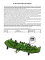 5
5
-
 6
6
-
 7
7
-
 8
8
-
 9
9
-
 10
10
-
 11
11
-
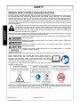 12
12
-
 13
13
-
 14
14
-
 15
15
-
 16
16
-
 17
17
-
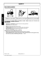 18
18
-
 19
19
-
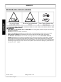 20
20
-
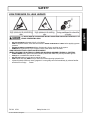 21
21
-
 22
22
-
 23
23
-
 24
24
-
 25
25
-
 26
26
-
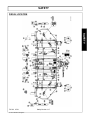 27
27
-
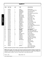 28
28
-
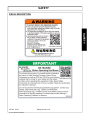 29
29
-
 30
30
-
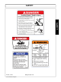 31
31
-
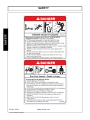 32
32
-
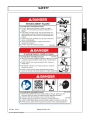 33
33
-
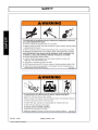 34
34
-
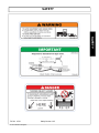 35
35
-
 36
36
-
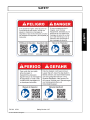 37
37
-
 38
38
-
 39
39
-
 40
40
-
 41
41
-
 42
42
-
 43
43
-
 44
44
-
 45
45
-
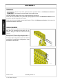 46
46
-
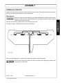 47
47
-
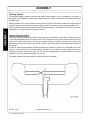 48
48
-
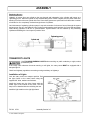 49
49
-
 50
50
-
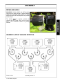 51
51
-
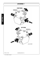 52
52
-
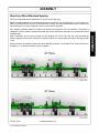 53
53
-
 54
54
-
 55
55
-
 56
56
-
 57
57
-
 58
58
-
 59
59
-
 60
60
-
 61
61
-
 62
62
-
 63
63
-
 64
64
-
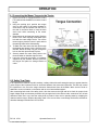 65
65
-
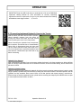 66
66
-
 67
67
-
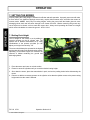 68
68
-
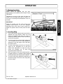 69
69
-
 70
70
-
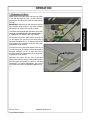 71
71
-
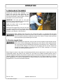 72
72
-
 73
73
-
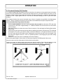 74
74
-
 75
75
-
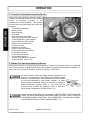 76
76
-
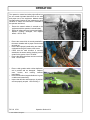 77
77
-
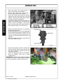 78
78
-
 79
79
-
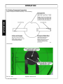 80
80
-
 81
81
-
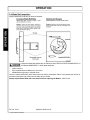 82
82
-
 83
83
-
 84
84
-
 85
85
-
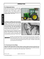 86
86
-
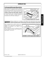 87
87
-
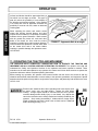 88
88
-
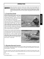 89
89
-
 90
90
-
 91
91
-
 92
92
-
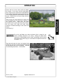 93
93
-
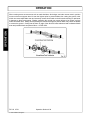 94
94
-
 95
95
-
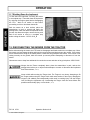 96
96
-
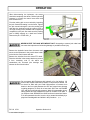 97
97
-
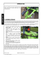 98
98
-
 99
99
-
 100
100
-
 101
101
-
 102
102
-
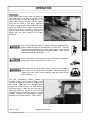 103
103
-
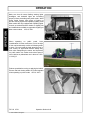 104
104
-
 105
105
-
 106
106
-
 107
107
-
 108
108
-
 109
109
-
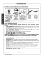 110
110
-
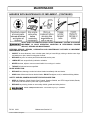 111
111
-
 112
112
-
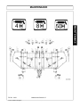 113
113
-
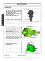 114
114
-
 115
115
-
 116
116
-
 117
117
-
 118
118
-
 119
119
-
 120
120
-
 121
121
-
 122
122
-
 123
123
-
 124
124
-
 125
125
-
 126
126
-
 127
127
-
 128
128
-
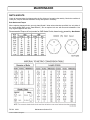 129
129
-
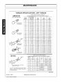 130
130
-
 131
131
-
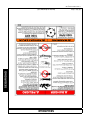 132
132
-
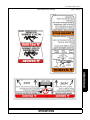 133
133
-
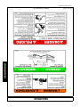 134
134
-
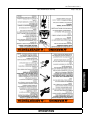 135
135
-
 136
136
-
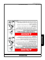 137
137
-
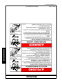 138
138
-
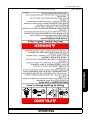 139
139
-
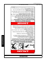 140
140
-
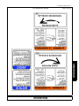 141
141
-
 142
142
-
 143
143
-
 144
144
-
 145
145
-
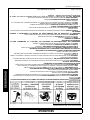 146
146
-
 147
147
-
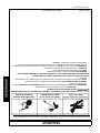 148
148
-
 149
149
-
 150
150
-
 151
151
-
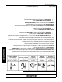 152
152
-
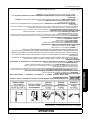 153
153
-
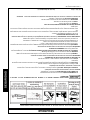 154
154
-
 155
155
-
 156
156
-
 157
157
-
 158
158
-
 159
159
-
 160
160
-
 161
161
-
 162
162
-
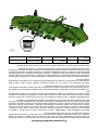 163
163
-
 164
164


Schulte FX-742 El manual del propietario
- Categoría
- Cortadoras de césped
- Tipo
- El manual del propietario
en otros idiomas
- English: Schulte FX-742 Owner's manual
Artículos relacionados


Otros documentos
-
Bush Hog Flex-Wing Rotary Cutter El manual del propietario
-
-
-
-
RHINO 2150 15′ Flex-Wing Manual de usuario
-
Servis-Rhino FR162 Manual de usuario
-