Tripp Lite Smart Rack Enclosures El manual del propietario
- Tipo
- El manual del propietario

1
SmartRack
®
Enclosures
(Series Numbers: AG-039A, AGAC7006, ACAD7761,
AG-0324, AG-00BE, AG-0325, AGAC7454)
Owner’s Manual
Important Safety Instructions 2
Overview 2
Feature Identification 3
Enclosure Installation 4
Preparation 4
Unpacking 4
Placement 5
Leveling 6
Ground Connection 6
Enclosure Configuration 7
Adding or Removing Front and Rear Doors 7
Reversing Front Door 7
Adding or Removing Roof Panel 9
Adding or Removing Side Panels 9
Adjusting Mounting Rails and Cable Management Rails 10
Combining (Baying) Enclosures 11
Equipment Installation 11
Installing or Removing Cage Nuts 12
Specifications 12
Storage and Service 14
Warranty and Product Registration 14
Español 15
Français 29
Русский
43
1111 W. 35th Street, Chicago, IL 60609 USA • www.tripplite.com/support
Copyright © 2018 Tripp Lite. All trademarks are the sole property of their respective owners.
PROTECT YOUR INVESTMENT!
Register your product for quicker service and ultimate peace of mind.
You could also win an ISOBAR6ULTRA surge protector—a $100 value!
www.tripplite.com/warranty

2
Important Safety Instructions
Overview
SAVE THESE INSTRUCTIONS
All sections of this manual contain instructions and warnings that should be followed during the installation and use of the SmartRack Enclosures
described in this manual. Read all instructions and warnings thoroughly before attempting to move, install or use the SmartRack Enclosures described
in this manual. Failure to comply will create a risk of personal injury and property damage and may invalidate the warranty.
• Keep the enclosure in a controlled indoor environment, away from moisture, temperature extremes, flammable liquids and gasses, conductive
contaminants, dust and direct sunlight.
• Leave adequate space at the front and rear of the enclosure for proper ventilation. Do not block, cover or insert objects into the external ventilation
openings of the enclosure.
• The enclosure is extremely heavy. Use caution when handling the enclosure. Do not attempt to unpack, move or install it unassisted. Use a mechanical
device such as a forklift or pallet jack to move the enclosure in the shipping container.
• Do not place any object on the enclosure, especially containers of liquid, and do not attempt to stack the enclosures.
• Inspect the shipping container and the enclosure for shipping damage. Do not use the enclosure if it is damaged.
• Leave the enclosure in the shipping container until it has been moved as close to the final installation location as possible. The casters are designed for
minor position adjustments within the final installation area only. The casters are not designed for moving the enclosure over longer distances.
• The casters are not designed to provide long-term support for the enclosure after final installation. Use the levelers to provide long-term support.
• Install the enclosure in a structurally sound area with a level floor that is able to bear the weight of the enclosure, all equipment that will be installed in
the enclosure and any other enclosures and/or equipment that will be installed nearby.
• Install the cabinet securely to the building structure, using the shipping brackets as illustrated in the Enclosure Installation section of this manual.
• Do not push the enclosure from the side panels to move it. Pushing from the side panels will cause a tipping hazard.
• When rolling the enclosure on its casters, always push it from behind, never pull it toward you.
• A rolling enclosure can cause personal injury and property damage if not properly supervised. If rolling the enclosure down a ramp is required, use
extreme caution. Do not attempt to use ramps that have a slope steeper than 1:12.
• Use caution when cutting packing materials. The enclosure could be scratched, causing damage not covered by the warranty.
• Save all packing materials for later use. Repacking and shipping the enclosure without the original packing materials may cause product damage that will
void the warranty.
• Do not re-ship the enclosure with additional equipment unless the enclosure was shipped with a special shock pallet (“SP1” models only). The combined weight of
the enclosure and installed equipment must not exceed the load capacity of the pallet. Tripp Lite is not responsible for any damage that occurs during re-shipment.
• Use of this equipment in life support applications where failure of this equipment can reasonably be expected to cause the failure of the life support
equipment or to significantly affect its safety or effectiveness is not recommended.
SmartRack Enclosures accommodate all standard 19-inch rackmount equipment, regardless of vendor, and ship fully assembled for quick and easy
deployment. They feature adaptable, heavy-duty cabinets in 24U, 42U, 45U, 47U and 48U heights, with or without side panels. Several models are
available with an integrated shock pallet that allows resellers, integrators and enterprise customers to pre-configure equipment and re-ship the enclosures
to the final installation site.
SmartRack Enclosures have variable mounting depths, ideal for servers. Integrated baying hardware enables cost-effective, orderly and efficient expansion.
The cabinets include quick-release doors and side panels for convenient maintenance and split rear doors for improved access and reduced clearance
requirements. Front access doors are reversible for installation flexibility. Front and rear doors and side panels are lockable.
Available SmartRack Enclosures
Model # Rack Height Side Panels Shock Pallet
SR24UB 24U Yes No
SR24UBEXP 24U No No
SR24UBEXPSP1 24U No Yes
SR24UBSP1 24U Yes Yes
SR25UB 25U Yes Yes
SR42UB 42U Yes No
SRX42UB* 42U Yes No
SR42UBCL 42U Yes No
SR42UBDP 42U Yes No
SRX42UBDP* 42U Yes No
SRX42UBDPEXP* 42U No No
SR42UBDPWD 42U Yes No
SRX42UBDPWD* 42U Yes No
SRX42UBDPWDEXP* 42U No No
SR42UBEXP 42U No No
SRX42UBEXP* 42U No No
SR42UBEXPND 42U No No
SR42UBEXPSP1 42U No Yes
SR42UBSP1 42U Yes Yes
SR42UBWD 42U Yes No
Model # Rack Height Side Panels Shock Pallet
SRX42UBWD* 42U Yes No
SRX42UBWDEXP* 42U No No
SR42UBWDCL 42U Yes No
SR45UB 45U Yes No
SRX47UB* 47U Yes No
SRX47UBEXP* 47U No No
SRX47UBDP* 47U Yes No
SRX47UBDPEXP* 47U No No
SRX47UBWD* 47U Yes No
SRX47UBWDEXP* 47U No No
SRX47UBDPWD* 47U Yes No
SRX47UBDPWDEXP* 47U No No
SR48UB 48U Yes No
SR48UBCL 48U Yes No
SR48UBDP 48U Yes No
SR48UBDPWD 48U Yes No
SR48UBEXP 48U No No
SR48UBEXPSP1 48U No Yes
SR48UBSP1 48U Yes Yes
*SRX-Series SmartRack Enclosure
See the Specifications section for more information.

3
Feature Identification
Model SR42UB is shown. The other models have similar features, with the differences noted.
1
Roof Panel
2
Locking Split Rear Doors
3
Locking Side Panels (24U enclosures use 2 side panels instead of 4. Side panels are not included with “EXP” models.)
4
Cable Management Rails
5
Casters
A
and Levelers
B
6
Mounting Rails (Provide horizontal and vertical mounting points for equipment.)
7
Keys (One for the doors and one for the side panels.)
8
Locking Reversible Front Door
Not Shown: Mounting hardware, documentation, shipping brackets and other shipping materials.
1
2
3
4
6
8
5
7
A
B
3
6

4
Caution! Read All Instructions and Warnings Before Installation!
WARNING: The rack enclosure is extremely heavy. Do not attempt to unpack, move or install the enclosure without assistance. Until it has
been properly installed and stabilized, the enclosure is prone to tipping and could cause property damage and/or personal injury. Use extreme
caution when handling the enclosure and be sure to follow all handling and installation instructions. Do not attempt to install equipment
without first stabilizing the enclosure.
Preparation
The enclosure must be installed in a structurally sound area with a level floor that is able to bear the weight of the enclosure, all the equipment that will be
installed in the enclosure and any other enclosures and/or equipment that will be installed nearby. Before unpacking the enclosure, you should transport the
shipping container closer to the final installation location to minimize the distance you will need to move the unit after the protective packaging has been
removed. If you plan to store the enclosure for an extended period before installation, follow the instructions in the Storage and Service section.
You need several tools (user-supplied):
• 13 mm Open-end Wrench
• 18 mm Open-end Wrench
• Utility Blade
• Carpenter's Level
• Phillips-head Screwdriver
• 5/32" Allen Wrench
You also need the following hardware (included):
• (60) Phillips-head Mounting Screws (M6 x 5/8")
• (60) Cage Nuts (M6)
• (60) Nylon Cup Washers
Unpacking
NOTE: If the enclosure is an “SP1” model with a shock pallet, follow the special unpacking instructions attached to the shipping container
instead of the unpacking instructions in this section. All warnings still apply.
1
2
3
Enclosure Installation
1
Confirm that the shipping container is upright and stable, then use a utility blade to cut the shrink-
wrap securing the corner protectors. Apply the utility blade directly over the corner protectors to
prevent the utility blade from scratching the enclosure or cutting the heavy protective plastic bag
beneath the shrink-wrap. WARNING: Do not scratch the enclosure or cut the heavy plastic
bag beneath the shrink-wrap. Do not push or pull the enclosure while unpacking.
2
Remove the corner protectors. Save all packing materials (including the pallet) for later use unless
you are certain they will not be required. The packing materials are recyclable.
3
Remove the heavy plastic bag surrounding the enclosure. Examine the enclosure for any damage or
loose parts. Confirm that all parts are present. If anything is missing or damaged, contact Tripp Lite
for assistance. Do not attempt to use the enclosure if it has been damaged.

5
Enclosure Installation
Unpacking (continued)
4
Use the key to open the enclosure's doors and locate the 2 shipping brackets
A
that attach the
enclosure to the shipping pallet. The brackets are located inside the enclosure.
Note: The keys are attached to the front of the enclosure.
5
Use a 13 mm open-end wrench to remove the shipping brackets. Be extremely careful, as the
enclosure could shift unexpectedly after bracket removal. Save the brackets and bracket hardware
for later use.
6
Position at least one person at the front of the enclosure and one person at the rear of the
enclosure. Slowly push the enclosure toward the back of the shipping pallet until all four casters go
over the edge of the pallet and touch the floor. WARNING: Use at least one assistant when
removing the enclosure from the pallet. Be extremely careful when moving the enclosure.
Placement
1
Use the casters to move the enclosure for a short distance over a level, smooth, stable surface by
pushing it from the front or rear (not the side panels). Do not attempt to roll the enclosure over
long distances. The enclosure should be moved close to its installation location inside its shipping
container before it is unpacked. (Use a forklift or pallet jack to move the shipping container.)
WARNING: Do not push or pull the enclosure at the side panels or pull the enclosure
toward you.
If required, the enclosure can be lifted by attaching 4 user-supplied M8 diameter eye bolts to the
threaded holes near the upper corners of the enclosure frame. Use steel bolts with an ISO strength
rating of 8.8 or higher. The 4 bolts can support the weight of the enclosure and up to 1000 lb (450
kg) of installed equipment. WARNING: Only experienced equipment operators should attempt to
lift the enclosure. Use appropriate equipment and follow all applicable safety procedures and
regulations.
A
4
5
6
1

6
Leveling
WARNING: Level the enclosure before attempting to install equipment. The casters are not designed to provide long-term support for the
enclosure. Use the levelers to provide long-term support. Install the enclosure in a structurally sound area with a level floor that is able to
bear the weight of the enclosure, all equipment that will be installed in the enclosure and any other enclosures and/or equipment that will be
installed nearby.
Ground Connection
All the parts of the enclosure are grounded to the frame of the enclosure. Use the enclosure's front or
rear threaded grounding point
A
and an M6 screw (included) to connect the frame of the enclosure
directly to your facility's earth ground connection with an 8 AWG (3.264 mm) wire. Route the ground
wire under the enclosure's frame to ensure unhindered door operation. WARNING: Attach each
enclosure to earth ground separately. Do not use the enclosure without an earth ground
connection.
EARTH
GROUND
FLOOR
1
2
3
A
B
4
A
A
Enclosure Installation
1
After the enclosure has been moved to the installation location, use a carpenter's level to check
the slope of the floor. If the floor slopes more than 1%, choose an alternate installation site.
2
Use an 18 mm open-end wrench to lower each leveler
A
until it reaches the floor. (There are 4
levelers, 2 at the front and 2 at the rear.) Make sure each leveler contacts the floor solidly.
Note: Lower a leveler by turning it clockwise; raise a leveler by turning it counter-clockwise.
3
After lowering each leveler, use the carpenter's level to confirm that the enclosure is level in all
directions. Adjust the levelers as required until the enclosure is level.
4
In order to secure the cabinet to the building structure for stability, attach the 2 shipping brackets
using the hardware that attached the enclosure to the shipping pallet. Use a 13 mm open-end
wrench to connect the brackets to the outer
A
or inner
B
bracket mounting points of the
enclosure. Attach the brackets to secure mounting points in the floor using user-supplied hardware
or Tripp Lite's SmartRack Bolt-Down Kit (Model: SRBOLTDOWN).

7
Enclosure Configuration
Adding or Removing Front and Rear Doors
WARNING: Do not attempt to add or remove doors without assistance.
Removing Door
1
Disconnect the door's ground wire.
2
Open the door until it is perpendicular (90 degrees) to the front of the enclosure.
3
Lift the door from the hinges and remove it from the enclosure.
To Reinstall Door, Reverse Steps 1-3
(Optional) If the enclosure is joined to another enclosure, turn the door back toward the enclosure as
you lift it from the hinges.
Reversing Front Door
WARNING: Do not attempt to reverse the front door without assistance.
1
Remove the screw connecting the ground wire to the inside of the door.
2
Remove the 2 screws connecting the door handle to the door. Remove the door handle.
90°
1
2
3
1
2

8
Enclosure Configuration
Reversing Front Door (continued)
3
Remove the screw and washer from the rear of the door handle and remove the latching
mechanism. Rotate the latch washer counter-clockwise 90 degrees and reverse the latch so it
points in the opposite direction, then use the screw and washer to re-attach the latch to the rear
of the door handle.
4
Remove the door by following the steps in the previous section.
5
Remove the door hinges from the enclosure, rotate them 180 degrees and attach them on the
opposite side of the enclosure.
Note: The alternate door hinge attachment points have plastic plugs in the screw holes. Remove
the plugs and insert them in the original door hinge attachment points.
6
Unscrew the 2 hinge mechanisms from the hinge openings inside the door, then reattach each of
them using the set of screw holes immediately opposite their original position.
7
Rotate the door 180 degrees and reinstall it on the enclosure. Remember to connect the ground
wire to the inside of the door, using the attachment point nearest the hinge at the top of the door.
The attachment point is marked with the ground connection symbol: .
8
Reinstall the door handle.
3
4
5
7
6
8

9
Enclosure Configuration
Adding or Removing Roof Panel
WARNING: Do not attempt to use the roof panel for weight-bearing purposes other than those explicitly described and approved by Tripp Lite.
Do not attempt to add or remove the roof panel without assistance.
Adding or Removing Side Panels
Removing Side Panel
1
Open the latch by sliding it downward.
2
Tilt the top of the panel away from the enclosure.
2
1
1
2
1
2
3
A
B
Removing Roof Panel
1
Pull the 2 pins near the rear of the roof panel. While holding the pins, push the roof panel upward.
2
Remove the roof panel tabs
A
from the roof panel attachment slots
B
in the enclosure frame.
3
Lift the roof panel from the enclosure.
To Reinstall Roof Panel, Reverse Steps 1-3

10
Adjusting Mounting Rails and Cable Management Rails
WARNING: Do not attempt to adjust rails without assistance. Do not attempt to adjust rails while equipment is installed in the enclosure. Do
not attempt to use rails without screws installed (6 per rail).
The 4 mounting rails are pre-installed to accommodate equipment with a mounting depth of 30 inches (762 mm). Do not adjust the mounting rails unless
your equipment requires a different mounting depth. The front and rear sets of rails can be adjusted independently in ¼-inch (6 mm) increments for
mounting depths between 4 inches (101.6 mm) and 42 inches (1066.8 mm).
4 5 6 3 4 5 6 7 8 9 0 1 2 3 4 5 6
8
4 5 6 5 6 7 8 9 0 1 2 3 4 5 6 0 1 2 3 4 5 6 7 8 9 0 1 2 3
5
3
A
B
C
1
2
3
A
Enclosure Configuration
Adding or Removing Side Panels (continued)
3
Lift the panel away from the brace that supports it.
To Reinstall Side Panel, Reverse Steps 1-3
1
Each rail is connected to the enclosure with 6 screws - 1 pair at the upper beam
A
, 1 pair at the
middle beam
B
and 1 pair at the lower beam
C
.
2
Remove the screws fastening each of the rear mounting rails to the enclosure. (If adjustment of
the front rails is required, you can also remove the screws from the front rails.)
3
Slide the mounting rails to the desired depth and reattach them using the screws you removed in
Step 2. The rail attachment points are numbered
A
to help you align each pair of rails at the
same depth.
The depth of the 2 cable management rails can be adjusted using the same method.

11
Enclosure Configuration
Equipment Installation
Combining (Baying) Enclosures
WARNING: Combining enclosures is not a substitute for stabilizing the enclosures. Each enclosure in a bay of combined enclosures requires
the same stabilizing measures as a standalone enclosure.
WARNING: Do not install equipment until you have stabilized the enclosure. Install heavier equipment first and install it toward the bottom of
the enclosure. Install equipment starting from the bottom of the enclosure and proceeding toward the top of the enclosure - never the
reverse. If using sliding equipment rails, be careful when extending the rails. Do not extend more than one set of sliding equipment rails at
one time. Avoid extending sliding equipment rails near the top of the enclosure.
Note: The square holes at the middle of each rack unit are numbered and also include a small notch to aid identification. A single rack unit includes the
space occupied by the numbered hole and the holes directly above and below.
90°
24
25
26
27
28
29
23
22
21
20
19
18
24
25
26
27
28
29
23
22
21
20
19
18
24
24
2
1 Rack Unit
3
4
2
1
C
D
A
B
1
Arrange the enclosures in the correct position for baying.
2
Each enclosure includes 4 baying brackets
A
that correspond to baying connection points
B
on
the adjoining enclosure. The baying connection points already contain screws. Remove the screw
from each baying connection point in the adjoining enclosure.
3
Loosen the screw in each baying bracket and turn each bracket 90 degrees toward the adjoining
enclosure, aligning each bracket with the corresponding baying connection point on the adjoining
enclosure.
4
Connect each bracket to the adjoining enclosure using the screws you removed in step 2, but do
not tighten the screws completely. Adjust the position of the enclosures as needed. If you want the
centers of the enclosures to be 24 inches (61 cm) apart/29.9 inches (76 cm) for the SR42UBWD,
use the outside hole of the bracket
C
. If you want the centers to be 60 cm (23.6 inches)
apart/75 cm (29.5 inches) for the SR42UBWD, use the middle hole of the bracket
D
. After
connecting all brackets and confirming that the enclosures do not need further adjustment, tighten
all screws.
Note: You may wish to remove the doors from the enclosures before combining them. Reinstalling
the doors afterward is optional. Remove the interior side panels before baying enclosures if you
wish to enable access between enclosures.

12
Installing or Removing Cage Nuts
WARNING: The flanges of the cage nuts should engage the sides of the square opening in the rail, not the top and bottom. Follow the
instructions in your equipment documentation to ensure proper installation of your equipment.
20
19
18
22
21
20
19
18
22
21
20
19
18
22
21
20
19
18
22
21
1
2
3
4
Equipment Installation
Specifications
Installing Cage Nuts
1
Locate the numbered square openings in the mounting rails where you plan to install your
equipment. You will install cage nuts (included) into the square openings in order to provide an
attachment point for the mounting screws (included).
Note: Consult your equipment documentation to determine how many cage nuts will be required
and where they will need to be installed.
2
From the inside of the mounting rail, insert one of the flanges of the cage nut through the square
opening. Press it against the side of the square opening. Each flange should engage one side of
the square opening, not the top or bottom.
3
Compress the cage nut at the sides slightly to allow the remaining flange to fit through the square
opening. When the cage nut is properly installed, both flanges will protrude through the square
opening and will be visible on the outer surface of the mounting rail. Repeat steps 1-3 until all
required cage nuts are installed.
4
After installing the required cage nuts, use the included mounting screws and cup washers to
secure your equipment to the rack rail. Place the cup washers between the screws and the
equipment mounting brackets.
Note: Your equipment may also include mounting hardware. Read the mounting instructions that
came with your equipment before installing your equipment.
To Remove Cage Nuts, Reverse Steps 1-3
Note: You may wish to use a cage nut tool (user-supplied) to aid cage nut installation and removal.
Load Capacity* Unit Dimensions Shipping Dimensions
Model Static Rolling Height Width Depth Weight Height Width Depth Weight
SR24UB 3000 lb.
(1363 kg)
2250 lb.
(1022 kg)
47.25 in.
(1200 mm)
23.63 in.
(600 mm)
43 in.
(1092 mm)
190 lb.
(86 kg)
51.4 in.
(1306 mm)
26 in.
(650 mm)
45 in.
(1140 mm)
232 lb.
(105 kg)
SR24UBEXP 3000 lb.
(1363 kg)
2250 lb.
(1022 kg)
47.25 in.
(1200 mm)
23.63 in.
(600 mm)
43 in.
(1092 mm)
145 lb.
(66 kg)
51.4 in.
(1306 mm)
26 in.
(650 mm)
45 in.
(1140 mm)
187 lb.
(85 kg)
SR24UBSP1 3000 lb.
(1363 kg)
2250 lb.
(1022 kg)
47.25 in.
(1200 mm)
23.63 in.
(600 mm)
43 in.
(1092 mm)
190 lb.
(86 kg)
51.4 in.
(1306 mm)
28 in.
(705 mm)
47 in.
(1194 mm)
240 lb.
(109 kg)
SR24UBEXPSP1 3000 lb.
(1363 kg)
2250 lb.
(1022 kg)
47.25 in.
(1200 mm)
23.63 in.
(600 mm)
43 in.
(1092 mm)
145 lb.
(66 kg)
51.4 in.
(1306 mm)
28 in.
(705 mm)
47 in.
(1194 mm)
195 lb.
(88 kg)
SR25UB 3000 lb.
(1363 kg)
2250 lb.
(1022 kg)
49.00 in.
(1245 mm)
23.63 in.
(600 mm)
43 in.
(1092 mm)
195 lb.
(88.6 kg)
53.5 in.
(1358.9 mm)
24 in.
(609.6 mm)
43.0 in.
(1092.2 mm)
237.0 lb.
(107.5 kg)
SR42UB 3000 lb.
(1363 kg)
2250 lb.
(1022 kg)
78.5 in.
(1994 mm)
23.63 in.
(600 mm)
43 in.
(1092 mm)
286 lb.
(130 kg)
85 in.
(2149 mm)
26 in.
(650 mm)
45 in.
(1140 mm)
328 lb.
(149 kg)

13
Specifications
Load Capacity* Unit Dimensions Shipping Dimensions
Model Static Rolling Height Width Depth Weight Height Width Depth Weight
SRX42UB** 3000 lb.
(1363 kg)
2250 lb.
(1022 kg)
78.5 in.
(1994 mm)
23.63 in.
(600 mm)
41.25 in.
(1048 mm)
298.98 lb.
(135.62 kg)
83.43 in.
(2118 mm)
25.75 in.
(654 mm)
42.85 in.
(1088.4 mm)
331.06 lb.
(150.17 kg)
SR42UBCL 3000 lb.
(1363 kg)
2250 lb.
(1022 kg)
78.5 in.
(1994 mm)
23.63 in.
(600 mm)
43 in.
(1092 mm)
305 lb.
(138 kg)
85 in.
(2149 mm)
26 in.
(650 mm)
45 in.
(1140 mm)
347 lb.
(157 kg)
SR42UBDP 3000 lb.
(1363 kg)
2250 lb.
(1022 kg)
78.5 in.
(1994 mm)
23.63 in.
(600 mm)
47.3 in.
(1200 mm)
315 lb.
(143 kg)
85 in.
(2149 mm)
26 in.
(650 mm)
45 in.
(1143 mm)
367 lb.
(167 kg)
SRX42UBDP** 3000 lb.
(1363 kg)
2250 lb.
(1022 kg)
78.5 in.
(1994 mm)
23.63 in.
(600 mm)
49 in.
(1246 mm)
323.20 lb.
(146.60 kg)
83.43 in.
(2118 mm)
25.75 in.
(654 mm)
50.72 in.
(1288.4 mm)
358.74 lb.
(162.72 kg)
SRX42UBDPEXP**
3000 lb.
(1363 kg)
2250 lb.
(1022 kg)
78.5 in.
(1994 mm)
23.63 in.
(600 mm)
49 in.
(1246 mm)
234.51 lb.
(106.37 kg)
83.43 in.
(2118 mm)
25.75 in.
(654 mm)
50.72 in.
(1288.4 mm)
270.05 lb.
(122.49 kg)
SR42UBDPWD 3000 lb.
(1363 kg)
2250 lb.
(1022 kg)
78.5 in.
(1994 mm)
29.53 in.
(750 mm)
47.3 in.
(1200 mm)
342 lb.
(155 kg)
85 in.
(2149 mm)
26 in.
(660 mm)
45 in.
(1143 mm)
404 lb.
(183 kg)
SRX42UBDPWD**
3000 lb.
(1363 kg)
2250 lb.
(1022 kg)
78.5 in.
(1994 mm)
31.5 in.
(800 mm)
49 in.
(1246 mm)
374.58 lb.
(169.91 kg)
83.43 in.
(2118 mm)
33.46 in.
(850 mm)
50.72 in.
(1288.4 mm)
422.55 lb.
(191.65 kg)
SRX42UBDPWDEXP**
3000 lb.
(1363 kg)
2250 lb.
(1022 kg)
78.5 in.
(1994 mm)
31.5 in.
(800 mm)
49 in.
(1246 mm)
285.27 lb.
(129.39 kg)
83.43 in.
(2118 mm)
33.46 in.
(850 mm)
50.72 in.
(1288.4 mm)
333.23 lb.
(151.15 kg)
SR42UBEXP 3000 lb.
(1363 kg)
2250 lb.
(1022 kg)
78.5 in.
(1994 mm)
23.63 in.
(600 mm)
43 in.
(1092 mm)
209 lb.
(95 kg)
85 in.
(2149 mm)
26 in.
(650 mm)
45 in.
(1140 mm)
251 lb.
(114 kg)
SRX42UBEXP** 3000 lb.
(1363 kg)
2250 lb.
(1022 kg)
78.5 in.
(1994 mm)
23.63 in.
(600 mm)
41.25 in.
(1048 mm)
224.75 lb.
(101.94 kg)
83.43 in.
(2118 mm)
25.75 in.
(654 mm)
42.85 in.
(1088.4 mm)
256.82 lb.
(116.50 kg)
SR42UBEXPND 3000 lb.
(1363 kg)
2250 lb.
(1022 kg)
78.5 in.
(2261 mm)
23.63 in.
(600 mm)
43 in.
(1092 mm)
161 lb.
(73.03 kg)
84 in.
(2133.6 mm)
28 in.
(711.2 mm)
47 in.
(1193.8 mm)
211 lb.
(95.7 kg)
SR42UBEXPSP1 3000 lb.
(1363 kg)
2250 lb.
(1022 kg)
78.5 in.
(1994 mm)
23.63 in.
(600 mm)
43 in.
(1092 mm)
203 lb.
(92 kg)
84 in.
(2146 mm)
28 in.
(705 mm)
47 in.
(1194 mm)
253 lb.
(115 kg)
SR42UBSP1 3000 lb.
(1363 kg)
2250 lb.
(1022 kg)
78.5 in.
(1994 mm)
23.63 in.
(600 mm)
43 in.
(1092 mm)
286 lb.
(130 kg)
84 in.
(2146 mm)
28 in.
(705 mm)
47 in.
(1194 mm)
336 lb.
(152 kg)
SR42UBWD 3000 lb.
(1363 kg)
2250 lb.
(1022 kg)
78.5 in.
(1994 mm)
29.53 in.
(750 mm)
43 in.
(1092 mm)
313 lb.
(142 kg)
85 in.
(2149 mm)
26 in.
(660 mm)
45 in.
(1140 mm)
365 lb.
(166 kg)
SRX42UBWD** 3000 lb.
(1363 kg)
2250 lb.
(1022 kg)
78.5 in.
(1994 mm)
31.5 in.
(800 mm)
41.25 in.
(1048 mm)
349.53 lb.
(158.55 kg)
83.43 in.
(2118 mm)
33.46 in.
(850 mm)
42.85 in.
(1088.4 mm)
392.72 lb.
(178.14 k)
SRX42UBWDEXP**
3000 lb.
(1363 kg)
2250 lb.
(1022 kg)
78.5 in.
(1994 mm)
31.5 in.
(800 mm)
41.25 in.
(1048 mm)
275.30 lb.
(124.87 kg)
83.43 in
(2118 mm)
33.46 in.
(850 mm)
42.85 in.
(1088.4 mm)
318.49 lb.
(144.46 kg)
SR42UBWDCL 3000 lb.
(1363 kg)
2250 lb.
(1022 kg)
78.5 in.
(1994 mm)
29.53 in.
(750 mm)
43 in.
(1092 mm)
304 lb.
(138 kg)
85 in.
(2149 mm)
26 in.
(660 mm)
45 in.
(1140 mm)
346 lb.
(157 kg)
SR45UB 3000 lb.
(1363 kg)
2250 lb.
(1022 kg)
84 in.
(2133.6 mm)
23.63 in.
(600 mm)
43 in.
(1092 mm)
305 lb.
(138 kg)
92.5 in.
(2298.7 mm)
26 in.
(650 mm)
45 in.
(1140 mm)
347 lb.
(157 kg)
SRX47UB** 3000 lb.
(1363 kg)
2250 lb.
(1022 kg)
87.2 in.
(2215 mm)
23.63 in.
(600 mm)
41.25 in.
(1048 mm)
326.23 lb.
(147.98 kg)
87.2 in.
(2215 mm)
25.75 in.
(654 mm)
42.85 in.
(1088.4 mm)
358.31 lb.
(162.53 kg)
SRX47UBEXP** 3000 lb.
(1363 kg)
2250 lb.
(1022 kg)
87.2 in.
(2215 mm)
23.63 in.
(600 mm)
41.25 in.
(1048 mm)
326.23 lb.
(147.98 kg)
87.2 in.
(2215 mm)
25.75 in.
(654 mm)
42.85 in.
(1088.4 mm)
358.31 lb.
(162.53 kg)
SRX47UBDP** 3000 lb.
(1363 kg)
2250 lb.
(1022 kg)
87.2 in.
(2215 mm)
23.63 in.
(600 mm)
41.25 in.
(1048 mm)
242.90 lb.
(110.18 kg)
87.2 in.
(2215 mm)
25.75 in.
(654 mm)
42.85 in.
(1088.4 mm)
274.98 lb.
(124.73 kg)
SRX47UBDPEXP**
3000 lb.
(1363 kg)
2250 lb.
(1022 kg)
87.2 in.
(2215 mm)
23.63 in.
(600 mm)
49 in.
(1246 mm)
352.29 lb.
(159.80 kg)
87.2 in.
(2215 mm)
25.75 in.
(654 mm)
50.72 in.
(1288.4 mm)
387.83 lb.
(175.92 kg)
SRX47UBWD** 3000 lb.
(1363 kg)
2250 lb.
(1022 kg)
87.2 in.
(2215 mm)
23.63 in.
(600 mm)
49 in.
(1246 mm)
252.04 lb.
(114.33 kg)
87.2 in.
(2215 mm)
25.75 in.
(654 mm)
50.72 in.
(1288.4 mm)
287.58 lb.
(130.45 kg)
SRX47UBWDEXP**
3000 lb.
(1363 kg)
2250 lb.
(1022 kg)
87.2 in.
(2215 mm)
31.5 in.
(800 mm)
41.25 in.
(1048 mm)
381.42 lb.
(173.01 kg)
87.2 in.
(2215 mm)
33.46 in.
(850 mm)
42.85 in.
(1088.4 mm)
424.60 lb.
(192.60 kg)
SRX47UBDPWD**
3000 lb.
(1363 kg)
2250 lb.
(1022 kg)
87.2 in.
(2215 mm)
31.5 in.
(800 mm)
41.25 in.
(1048 mm)
298.09 lb.
(135.21 kg)
87.2 in.
(2215 mm)
33.46 in.
(850 mm)
42.85 in.
(1088.4 mm)
341.27 lb.
(154.80 kg)
SRX47UBDPWDEXP**
3000 lb.
(1363 kg)
2250 lb
(1022 kg)
87.2 in.
(2215 mm)
31.5 in.
(800 mm)
49 in.
(1246 mm)
408.30 lb.
(185.20 kg)
87.2 in.
(2215 mm)
33.46 in.
(850 mm)
50.72 in.
(1288.4 mm)
456.27 lb.
(206.96 kg)
SR48UB 3000 lb.
(1363 kg)
2250 lb.
(1022 kg)
89 in.
(2261 mm)
23.63 in.
(600 mm)
43 in.
(1092 mm)
315 lb.
(143 kg)
95 in.
(2416 mm)
26 in.
(650 mm)
45 in.
(1140 mm)
357 lb.
(162 kg)
SR48UBCL 3000 lb.
(1363 kg)
2250 lb.
(1022 kg)
89 in.
(2261 mm)
23.63 in.
(600 mm)
43 in.
(1092 mm)
334 lb.
(151 kg)
95 in.
(2416 mm)
26 in.
(650 mm)
45 in.
(1140 mm)
376 lb.
(171 kg)
SR48UBDPWD 3000 lb.
(1363 kg)
2250 lb.
(1022 kg)
89 in.
(2261 mm)
29.53 in.
(750 mm)
47.3 in.
(1200 mm)
378 lb.
(171.5 kg)
26 in.
(660 mm)
45 in.
(1143 mm)
53 in.
(1340 mm)
440 lb.
(200 kg)
SR48UBEXP 3000 lb.
(1363 kg)
2250 lb.
(1022 kg)
89 in.
(2261 mm)
23.63 in.
(600 mm)
43 in.
(1092 mm)
225 lb.
(102 kg)
95 in.
(2416 mm)
26 in.
(650 mm)
45 in.
(1140 mm)
267 lb.
(121 kg)
SR48UBEXPSP1 3000 lb.
(1363 kg)
2250 lb.
(1022 kg)
89 in.
(2261 mm)
23.63 in.
(600 mm)
43 in.
(1092 mm)
225 lb.
(102 kg)
95 in.
(2416 mm)
28 in.
(705 mm)
47 in.
(1194 mm)
213 lb.
(96.6 kg)
SR48UBSP1 3000 lb.
(1363 kg)
2250 lb.
(1022 kg)
89 in.
(2261 mm)
23.63 in.
(600 mm)
43 in.
(1092 mm)
315 lb.
(143 kg)
95 in.
(2416 mm)
26 in.
(660 mm)
45 in.
(1143 mm)
365 lb.
(166 kg)
SR48UBWD 3000 lb.
(1363 kg)
2250 lb.
(1022 kg)
89 in.
(2261 mm)
29.53 in.
(750 mm)
43 in.
(1092 mm)
343 lb.
(156 kg)
95 in.
(2416 mm)
26 in.
(660 mm)
45 in.
(1140 mm)
395 lb.
(179 kg)
*“SP1” models include a shock pallet that allows the enclosure to be shipped with pre-installed equipment. The maximum shipping capacity is 1250 lb (568 kg), including the weight of the enclosure and the
pre-installed equipment. **SRX-Series SmartRack Enclosure

14
5-Year Limited Warranty
Seller warrants this product, if used in accordance with all applicable instructions, to be free from original defects in material and workmanship for a period of 5 years from the date of initial purchase. If the
product should prove defective in material or workmanship within that period, Seller will repair or replace the product, in its sole discretion.
THIS WARRANTY DOES NOT APPLY TO NORMAL WEAR OR TO DAMAGE RESULTING FROM ACCIDENT, MISUSE, ABUSE OR NEGLECT. SELLER MAKES NO EXPRESS WARRANTIES OTHER THAN THE WARRANTY
EXPRESSLY SET FORTH HEREIN. EXCEPT TO THE EXTENT PROHIBITED BY APPLICABLE LAW, ALL IMPLIED WARRANTIES, INCLUDING ALL WARRANTIES OF MERCHANTABILITY OR FITNESS, ARE LIMITED IN
DURATION TO THE WARRANTY PERIOD SET FORTH ABOVE; AND THIS WARRANTY EXPRESSLY EXCLUDES ALL INCIDENTAL AND CONSEQUENTIAL DAMAGES. (Some states do not allow limitations on how long
an implied warranty lasts, and some states do not allow the exclusion or limitation of incidental or consequential damages, so the above limitations or exclusions may not apply to you. This warranty gives you
specific legal rights, and you may have other rights which vary from jurisdiction to jurisdiction).
WARNING: The individual user should take care to determine prior to use whether this device is suitable, adequate or safe for the use intended. Since individual applications are subject to great variation, the
manufacturer makes no representation or warranty as to the suitability or fitness of these devices for any specific application.
Product Registration
Visit www.tripplite.com/warranty today to register your new Tripp Lite product. You'll be automatically entered into a drawing for a chance to win a FREE Tripp Lite product!*
* No purchase necessary. Void where prohibited. Some restrictions apply. See Web site for details.
Tripp Lite follows a policy of continuous improvement. Product specifications are subject to change without notice.
Note on Labeling
This symbol is used on the product: Ground Connection
Warranty and Product Registration
1111 W. 35th Street, Chicago, IL 60609 USA • www.tripplite.com/support
Storage and Service
Storage
The enclosure should be stored in a controlled indoor environment, away from moisture, temperature extremes, flammable liquids and gasses, conductive
contaminants, dust and direct sunlight. Store the enclosure in its original shipping container if possible.
Service
Your Tripp Lite product is covered by the warranty described in this manual. A variety of Extended Warranty and On-Site Service Programs are also available
from Tripp Lite. For more information on service, visit www.tripplite.com/support. Before returning your product for service, follow these steps:
1. Review the installation and operation procedures in this manual to insure that the service problem does not originate from a misreading of the
instructions.
2. If the problem continues, do not contact or return the product to the dealer. Instead, visit www.tripplite.com/support.
3. If the problem requires service, visit www.tripplite.com/support and click the Product Returns link. From here you can request a Returned Material
Authorization (RMA) number, which is required for service. This simple on-line form will ask for your unit’s model and serial numbers, along with other
general purchaser information. The RMA number, along with shipping instructions will be emailed to you. Any damages (direct, indirect, special or
consequential) to the product incurred during shipment to Tripp Lite or an authorized Tripp Lite service center is not covered under warranty. Products
shipped to Tripp Lite or an authorized Tripp Lite service center must have transportation charges prepaid. Mark the RMA number on the outside of the
package. If the product is within its warranty period, enclose a copy of your sales receipt. Return the product for service using an insured carrier to the
address given to you when you request the RMA.

15
Estantes SmartRack
®
(Números de Serie: AG-039A, AGAC7006, ACAD7761,
AG-0324, AG-00BE, AG-0325, AGAC7454)
Manual del Propietario
Instrucciones de Seguridad Importantes 16
Descripción 16
Identificación de Características 17
Instalación del Estante 18
Preparación 18
Desempaque 18
Colocación 19
Nivelación 20
Conexión a Tierra 20
Configuración del Estante 21
Añadiendo o Removiendo las Puertas del 21
Frente y Traseras
Invirtiendo la Puerta Frontal 21
Añadiendo o Removiendo el Panel Superior/Techo 23
Añadiendo o Removiendo los Paneles Laterales 23
Ajustando los Rieles de Montaje y los Rieles para 24
el Manejo de los Cables
Combinando [Baying] Estantes 25
Instalación del Equipo 25
Instalar o Remover las Tuercas de Jaula 26
Especificaciones 26
Almacenaje y Servicio 28
Garantía 28
English 1
Français 29
Русский
43
1111 W. 35th Street, Chicago, IL 60609 USA • www.tripplite.com/support
Derechos de Autor © 2018 Tripp Lite. Todas la marcas registradas son totalmente propiedad de sus respectivos dueños.

16
Instrucciones de Seguridad Importantes
Descripción
CONSERVE ESTAS INSTRUCCIONES
Todas las secciones de este manual contienen instrucciones y advertencias que deberás seguirse durante la instalación y uso de los Estantes SmartRack
descritos en este manual. Lea cuidadosamente todas las instrucciones y advertencias antes de intentar mover, instalar o usar los Bastidores SmartRack
descritos en este manual. No adherirse a las instrucciones y advertencias de este manual crearán un riesgo de lesiones personales y daños a la
propiedad y puede invalidar las garantía.
• Mantenga el estante en un ambiente al interior controlado, lejos de la humedad, temperaturas extremas, líquidos y gases inflamables, contaminantes
conductores, polvo y luz solar directa.
• Deje un espacio adecuado al frente y atrás del estante para una ventilación adecuada. No bloque, cubra o inserte objetos en las aberturas de ventilación
externa del estante.
• El estante es extremadamente pesado. Tenga cuidado cuando maneje el estante. No intente desempacarlo, moverlo o instalarlo sin ayuda. Use algún
dispositivo mecánico como un montacargas o gato para tarima [pallet jack] para mover el estante y el contenedor de embarque.
• No coloque ningún objeto sobre el estante, especialmente envases con líquidos y no intente apilar los estantes.
• Inspeccione el contenedor de embarque y el estante por posibles daños en el envío. No use el estante si está dañado.
• Deje el estante en el contenedor de embarque hasta que haya sido movido tan cerca como sea posible a su ubicación final. Las ruedas están diseñadas para
ajuste de posición menores dentro del área de instalación final únicamente. Las ruedas no están diseñadas para par mover el estante sobre distancias más largas.
• Las ruedas no están diseñadas para dar soporte por largo tiempo al estante después de la instalación final. Use los niveladores/puntales para dar
soporte por largo tiempo.
• Instale el estante en un área estructuralmente sólida con un piso nivelado que sea capaz de resistir el peso del estante, a todo el equipo que vaya a ser
instalado en el estante y cualquier otro estante y/o equipo que vaya ser instalado cerca.
• Instale firmemente el gabinete a la estructura del edificio, usando los soportes de embarque como se ilustra en la sección de Instalación del Gabinete
de este manual.
• No empuje el estante de los paneles laterales para moverlo. Empujándolo de los paneles laterales puede causar una volcadura.
• Cuando mueva el estante sobre sus ruedas siempre empújelo desde atrás, nunca lo jale hacia usted.
• Un estante en movimiento puede ocasionar lesiones personales y daños ala propiedad si nos es supervisado adecuadamente. Si es necesario rodar
hacia abajo por una rampa al estante extreme precauciones. No intente usar rampas que tengan un declive mayor de 1:12.
• Sea precavido cuando corte el material de empaque. El estante se puede rayar causando un daño no cubierto por la garantía.
• Conserve todo el material de empaque para uso posterior. Reempacar y embarcar el estante sin el empaque original puede causar daños al producto
que anularán su garantía.
• No envíe el estante con equipo adicional al menos que el estante haya sido enviado con un shock pallet especial [Tarima de uso pesado] (Modelos
“SP1” únicamente). El peso combinado del estante y el equipo instalado no debe exceder la capacidad de la tarima. Tripp Lite no es responsable de
ningún daño que ocurra durante el reenvío.
• Use el uso de este equipo en aplicaciones de soporte de vida en donde la falla de este equipo pueda hacer suponer que causará la falla del equipo de
soporte de vida o significativamente afectar su seguridad o efectividad no es recomendado.
Los estantes SmartRack aceptan todos los equipos para montaje en bastidor estándar de 19 pulgadas, sin importa el proveedor y se entrega
completamente ensamblado para una instalación rápida y fácil. Cuentan con gabinetes adaptables de uso pesado en alturas de 24U, 42U, 45U, 47U y
48U, con o sin paneles laterales. Varios modelos están disponibles con un shock pallet integrado que permiten a los distribuidores, integradores y clientes
corporativos pre-configurar el equipo y reembarcar los estantes al sitio de la instalación final.
Los estantes SmartRack tienen profundidad para montaje variable, ideal para servidores. Hardware integrado para combinar estantes (baying) permite una
expansión costo-efectiva, ordenada y eficiente. Los gabinetes incluyen puertas y paneles laterales de rápida liberación para un adecuado mantenimiento y
puertas traseras divididas para un mejor acceso y requerimientos de espacio libre menores. Las puertas de acceso frontales son reversibles para flexibilidad
en la instalación. Las puertas del frente, las traseras y los paneles laterales cuentan con cerradura.
Estantes SmartRack
Modelo #
Altura del Rack
Paneles laterales
Shock Pallet
SR24UB 24U Sí No
SR24UBEXP 24U No No
SR24UBEXPSP1 24U No Sí
SR24UBSP1 24U Sí Sí
SR25UB 25U Sí Sí
SR42UB 42U Sí No
SRX42UB* 42U Sí No
SR42UBCL 42U Sí No
SR42UBDP 42U Sí No
SRX42UBDP* 42U Sí No
SRX42UBDPEXP* 42U No No
SR42UBDPWD 42U Sí No
SRX42UBDPWD* 42U Sí No
SRX42UBDPWDEXP* 42U No No
SR42UBEXP 42U No No
SRX42UBEXP* 42U No No
SR42UBEXPND 42U No No
SR42UBEXPSP1 42U No Sí
SR42UBSP1 42U Sí Sí
SR42UBWD 42U Sí No
Modelo #
Altura del Rack
Paneles laterales
Shock Pallet
SRX42UBWD* 42U Sí No
SRX42UBWDEXP* 42U No No
SR42UBWDCL 42U Sí No
SR45UB 45U Sí No
SRX47UB* 47U Sí No
SRX47UBEXP* 47U No No
SRX47UBDP* 47U Sí No
SRX47UBDPEXP* 47U No No
SRX47UBWD* 47U Sí No
SRX47UBWDEXP* 47U No No
SRX47UBDPWD* 47U Sí No
SRX47UBDPWDEXP* 47U No No
SR48UB 48U Sí No
SR48UBCL 48U Sí No
SR48UBDP 48U Sí No
SR48UBDPWD 48U Sí No
SR48UBEXP 48U No No
SR48UBEXPSP1 48U No Sí
SR48UBSP1 48U Sí Sí
*Serie SRX Estante SmartRack
Vea la sección Especificaciones para más información.

17
Identificación de Características
Se muestra el modelo SR42UB. Los otros modelos cuentan con características similares con las diferencias indicadas.
1
Panel Superior/Techo
2
Puertas Traseras de Dos Hojas con Cerradura
3
Paneles laterales con Cerradura
(Los estantes 24U usan 2 paneles laterales en lugar de 4. No se incluyen paneles laterales con los modelos “EXP”.)
4
Rieles para el Manejo de Cables
5
Ruedas
A
y Niveladores/Puntales
B
6
Rieles de Montaje (Proporciona puntos de montaje vertical y horizontal para el equipo.)
7
Llaves (Una para las puertas y una para los paneles laterales.)
8
Puerta Frontal Reversible con Cerradura
No se Muestra: Accesorios para montaje, documentación, ménsulas de embarque y otros materiales de embarque.
1
2
3
4
6
8
5
7
A
B
3
6

18
¡Precaución!
¡Lea Todas las Instrucciones y Advertencias Antes de la Instalación!
ADVERTENCIA: El estante es extremadamente pesado. No trate de desempacar, mover o instalar el estante sin ayuda. Hasta que no haya
sido adecuadamente instalado y estabilizado, el estante está propenso a volcarse y puede causar daños a la propiedad y/o lesiones
personales. Extreme precauciones cuando maneje el estante y asegúrese de seguir todas las instrucciones de manejo e instalación. No
intente instalar equipo sin antes haber estabilizado el estante.
Preparación
El estante debe instalarse en un área estructuralmente sólida con un piso nivelado que sea capaz de resistir el peso del estante, el equipo que será instalado
en el estante y otros estantes y/o equipos instalados en la cercanía. Antes de desempacar el estante, deberá transportar el contendor de embarque cerca de
de la ubicación de la instalación final a fin de minimizar la distancia que necesitará mover la unidad antes que el empaque de protección haya sido removido.
Si piensa almacenar el estante por un periodo prolongado antes de instalarlo, siga las instrucciones indicadas en la sección Almacenaje y Servicio.
Necesitará varias herramientas (suministradas por el usuario):
• Llave de tuercas de boca abierta de 13 mm
• Llave de tuercas de boca abierta de 18 mm
• Navaja/Cutter
• Nivel de Carpintero
• Desatornillador Phillips
• Llave Allen de 5/32”
También necesitará los siguientes accesorios (incluidos):
• (60) Tornillos de montaje Phillips (M6 x 5/8”)
• (60) Tuercas de Jaula (M6)
• (60) Rondana/arandela de copa de nylon
Desempaque
NOTA: Si el estante es un modelo “SP1”con shock pallet, siga las instrucciones de desempaque especiales adjuntas al contenedor de
empaque en lugar de las instrucciones de desempaque de esta sección. Todas las advertencias también aplican.
1
2
3
Instalación del Estante
1
Confirme que el contenedor de embarque esta hacia arriba y estable, a continuación utilice una
navaja para cortar la envoltura plástica [shrink wrap] conservando los protectores de las esquinas.
Use la navaja directamente en las esquinas para evitar dañar el estante o cortar la bolsa protectora
de plástico de uso pesado debajo de envoltura plástica. ADVERTENCIA: No raye el estante o
corte la bolsa de plástico de uso pesado debajo de la envoltura plástica. No empuje o jale
el estante mientras lo desempaca.
2
Remueva los protectores de las esquinas. Guarde todo el material de empaque (incluyendo la
tarima) para uso posterior a menos de que tenga la certeza que ya no lo va a necesitar. Los
materiales de empaque son reciclables.
3
Remueva la bolsa de plástico de uso pesado que cubre el estante. Examine el estante buscando
cualquier daño o partes sueltas. Confirme que están todas las partes y piezas. Si cualquier parte
está dañada o falta, comuníquese con Tripp Lite por ayuda. No trate de usar el estante si éste está
dañado.

19
Instalación del Estante
Desempaque (continuación)
4
Use la llave para abrir las puertas del estante y localice dos soportes de embarque
A
que fijan el
estante a la tarima de embarque. Los soportes están localizados en el interior del estante.
Nota: Las llaves están pegadas al frente del estante.
5
Use una llave de tuercas de boca abierta de 13 mm para quitar los soportes de embarque.
Extreme precauciones ya que el estante podría moverse inesperadamente después que haya
quitado los soportes. Conserve los soportes de embarque y los tornillos para uso posterior.
6
Coloque al menos una persona al frente del estante y otra en la parte de atrás del estante.
Lentamente empuje el estante hacia atrás de la tarima de embarque hasta que las cuatro ruedas
rebasen totalmente la parte posterior de la tarima y estén el piso. ADVERTENCIA: Use al menos
un ayudante para mover el estante de la tarima. Extreme precauciones cuando mueva el
estante.
Colocación
1
Use las ruedas para mover el estante cortas distancias sobre una superficie nivelada, suave y
estable empujándolo por atrás (no de los paneles laterales). No trate de rodar el estante por
largas distancias. El estante deberá moverse lo más cerca que sea posible al lugar de la ubicación
final dentro del contenedor de embarque antes de desempacarlo. (Use un montacargas o gato
para tarima para mover el contenedor de embarque.) ADVERTENCIA: No empuje o jale el
estante de los paneles laterales o jale el estante hacia usted.
Si es necesario el estante puede ser levantado fijando 4 armellas/cáncamos con diámetro M8,
suministradas por el usuario, a los perforaciones roscadas localizadas cerca de la esquina superior del
marco del estante. Use armellas de acero de resistencia ISO 8.8 ó mayor. Las 4 armellas resisten el
peso del bastidor y hasta 1000 lb (450 kg) de equipo instalado. ADVERTENCIA: Únicamente
operadores de equipo experimentados deben intentar levantar el estante. Use el equipo
apropiado y siga todos los procedimientos y regulaciones de seguridad aplicables.
A
4
5
6
1

20
Nivelación
ADVERTENCIA: Nivele el estante antes de intentar instalar el equipo. Las ruedas no están diseñadas para dar soporte por largo tiempo al
estante. Use los niveladores/puntales para dar soporte por largo tiempo. Instale el estante en un área estructuralmente sólida con un piso
nivelado que sea capaz de resistir el peso del estante, a todo el equipo que vaya a ser instalado en el estante y cualquier otro estante y/o
equipo que vaya ser instalado cerca.
Conexión a Tierra
Todas las partes del estante están conectadas a tierra al marco del estante. Use los puntos con
cuerda de conexión a tierra al frente o atrás del estante
A
y un tornillo M6 (incluido) para conectar el
marco del estante directamente a la tierra física de sus instalaciones con un cable 8 AWG (3.264
mm). Enrute el cable de tierra por debajo del marco del estante para asegurar una operación de la
puerta correctamente articulada. ADVERTENCIA: Fije la conexión a tierra de cada estante por
separado. No use el estante sin una adecuada conexión a tierra.
EARTH
GROUND
1
2
3
A
B
4
A
A
Instalación del Estante
1
Después que el estante haya sido movido al lugar de instalación, use un nivel de carpintero para
revisar la pendiente del piso. Si el piso tiene una pendiente de más de 1% escoja otro lugar para
la instalación.
2
Use una llave de tuercas de boca abierta de 18 mm para bajar cada nivelador/puntal
A
hasta que
toque el piso. (Hay 4 niveladores, 2 al frente y 2 atrás.) Asegúrese que cada nivelador haga
contacto sólido con el piso.
Nota: Baje un nivelador girándolo en el sentido de las manecillas del reloj, elévelo girándolo en
contra del sentido de las manecillas del reloj.
3
Después de bajar cada nivelador, use el nivel de carpintero para confirmar que el estante está
nivelado en todas las direcciones. Ajuste los niveladores hasta que el estante esté nivelado.
4
A fin de asegurar el gabinete a la estructura del edificio para tener estabilidad, fije los 2 soportes
de embarque usando los accesorios que sujetan el gabinete a la tarima de embarque. Use una
llave de tuercas de boca abierta de 13 mm para conectar los soportes de embarque a los puntos
de montaje externos
A
o internos
B
del estante. A continuación fije los soportes a los puntos de
anclaje en el piso utilizando tornillos suministrados por el usuario o con el juego SmartRack Bolt-
Down de Tripp Lite (Modelo: SRBOLTDOWN).
PISO
TIERRA
FÍSICA

21
Configuración del Estante
Añadiendo o Removiendo las Puertas del Frente y Traseras
ADVERTENCIA: No intente añadir o remover las puertas sin ayuda.
Removiendo la Puerta
1
Desconecte el cable de conexión a tierra de la puerta.
2
Abra la puerta hasta que este perpendicular (90 grados) al frente del estante.
3
Levante la puerta hasta sacarla de las bisagras y quítela del estante.
Para Reinstalar la Puerta, Revierta los Pasos 1 a 3
(Opcional) Si el estante está unido a otro estante, gire la puerta hacia el estante mientras la saca de
sus bisagras.
Invirtiendo la Puerta Frontal
ADVERTENCIA: No trate de invertir la puerta frontal sin ayuda.
1
Quite el tornillo que conecta el cable de tierra al interior de la puerta.
2
Quite los 2 tornillos que conectan la manija de la puerta a la puerta. Remueva la manija de la
puerta.
90°
1
2
3
1
2

22
Configuración del Estante
Invirtiendo la Puerta Frontal (continuación)
3
Remueva el tornillo y la arandela de atrás de la manija de la puerta y remueva el mecanismo de
cierre. Gire el pestillo en contra del sentido de las manecillas del reloj 90 grados e invierta el
pestillo de modo que apunte a la dirección contraria, a continuación use el tornillo y la arandela
par volver a fijar el pestillo a la parte posterior de la manija de al puerta.
4
Remueva la puerta siguiendo los pasos descrito en la sección anterior.
5
Remueva las bisagras de las puerta del estante, gírelas 180 grados y fíjelas al lado opuesto del
estante.
Nota: Los puntos alternos para fijar las bisagras de la puerta tienen tapas de plástico en las
perforaciones para los tornillos. Quite estas tapas e insértelos en los puntos de fijación de las
bisagras originales.
6
Desatornille el mecanismo de 2 bisagras de las aperturas de las bisagras en el interior de la
puerta, y luego fije cada una de ellas usando el juego de perforaciones inmediatamente opuesto a
la posición original.
7
Gire la puerta 180 grados y reinstálela en el estante. Recuerde conectar el cable de tierra al
interior de la puerta, usando el punto de fijación más cercano a la bisagra de la parte superior de
la puerta. El punto de fijación está marcado con el símbolo de conexión a tierra: .
8
Reinstale la manija de la puerta.
3
4
5
7
6
8

23
Configuración del Estante
Añadiendo o Removiendo el Panel Superior/Techo
ADVERTENCIA: No intente usar el panel superior para soportar pesos que no sean los explícitamente descritos y aprobados por Tripp Lite. No
intente poner o quitar el panel superior sin asistencia.
Añadiendo o Removiendo los Paneles Laterales
Removiendo el Panel Lateral
1
Abra el pestillo deslizándolo hacia abajo.
2
Incline la parte superior del panel hacia afuera del estante.
2
1
1
2
1
2
3
A
B
Removiendo el Panel Superior
1
Jale los 2 pasadores cerca de la parte trasera del panel superior. Mientras retiene los pasadores,
empuje el panel superior hacia arriba.
2
Remueva las lengüetas del panel superior
A
de las ranuras de fijación del panel superior
B
en el
marco del estante.
3
Levante el panel superior del estante.
Para Reinstalar el Panel Superior, Revierta los Pasos 1 a 3

24
Ajustando los Rieles de Montaje y los Rieles para el Manejo de los Cables
ADVERTENCIA: No intente ajustar los rieles sin asistencia. No intente ajustar los rieles con equipo instalado en el estante. No intente usar los
rieles sin haber instalado los tornillos (6 por riel).
Los 4 rieles de montaje están preinstalados para acomodar equipo con un fondo de montaje de 30 pulgadas (762 mm). No ajuste los rieles de montaje a
menos que su equipo requiera una diferente profundidad par su montaje. El juego de rieles del frente y traseros pueden justarse independientemente en
incrementos de ¼ de pulgada (6 mm) para fondos de montaje entre 4 pulgadas (101.6 mm) y 42 pulgadas (1066.8 mm).
4 5 6 3 4 5 6 7 8 9 0 1 2 3 4 5 6
8
4 5 6 5 6 7 8 9 0 1 2 3 4 5 6 0 1 2 3 4 5 6 7 8 9 0 1 2 3
5
3
A
B
C
1
2
3
A
Configuración del Estante
Añadiendo o Removiendo los Paneles Laterales (continuación)
3
Retire el panel de la abrazadera que lo soporta.
Para Reinstalar el Panel Lateral, Revierta los Pasos 1 a 3
1
Cada riel está conectado al estante con 6 tornillos - 1 par en la barra superior
A
, 1 par en la
barra de en medio
B
y 1 par en la barra de hasta abajo
C
.
2
Remueva los tornillos que sujetan cada uno de los rieles de montaje traseros al estante. (Si es
necesario ajustar los rieles frontales, también puede quitar los tornillos de los rieles frontales.)
3
Deslice los rieles de montaje a la profundidad deseada y vuélvalos a fijar utilizando los tornillos que
quitó en el paso 2 anterior. Puntos de fijación del riel están numerados
A
para ayudarlo a alinear
cada par de rieles a la misma profundidad.
El fondo de los 2 rieles para el manejo de cables pueden ajustarse usando el mismo
método.

25
Configuración del Estante
Instalación del Equipo
Combinando [Baying] Estantes
ADVERTENCIA: Combinar estantes no es un sustituto para estabilizar los estantes. Cada estante en una bahía de estantes combinados
requiere las mismas medidas de estabilización que un solo estante en forma independiente.
ADVERTENCIA: No instale ningún equipo hasta que haya estabilizado el estante. Instale primero el equipo más pesado e instálelo hacia el
fondo del bastidor. Instale el equipo comenzando desde el fondo del estante y continuando hacia la parte superior del estante - nunca al
revés . Si usa rieles para equipo deslizante sea cuidadoso cuando extienda los rieles. No extienda más de un juego de rieles a la vez. Evite
extender los rieles de los equipos deslizables cerca de la parte superior del estante.
Nota: Los hoyos cuadrados en medio de cada unidad de rack están numerados y también incluyen una pequeña muesca para ayudar a identificarlos. Una
sola unidad de rack incluye el espacio ocupado por el hoyo numerado y los hoyos directamente arriba y abajo.
90°
24
25
26
27
28
29
23
22
21
20
19
18
24
25
26
27
28
29
23
22
21
20
19
18
24
24
2
1 Rack Unit
3
4
2
1
C
D
A
B
1
Coloque los estantes en la posición correcta para combinarlos [baying].
2
Cada estante incluye cuatro tirantes
A
que corresponden a los puntos de conexión para combinar
[Baying]
B
al estante contiguo. Los puntos de conexión para unir los estantes ya tienen tornillos.
Remueva los tornillos de cada punto de unión en el estante contiguo.
3
Afloje los tornillos en cada tirante y gire cada tirante 90 grados hacia el estante contiguo,
alineando cada tirante con el correspondiente punto de unión en el estante contiguo.
4
Conecte cada tirante al estante contiguo utilizando los tornillos que quitó en el paso 2 anterior
pero no apriete los tornillos completamente. Ajuste la posición de los estantes conforme se
necesite. Si quiere que los centros de los estantes estén separados 24 pulgadas (61 cm)/29.9
pulgadas (76 cm) para el SR42UBWD, use la perforación exterior del tirante
C
. Si quiere que los
centros estén separados 60 cm (23.6 pulgadas)/75 cm (29.5 pulgadas) para el SR42UBWD, use
el hoyo de en medio
D
. Después de conectar todos los tirantes y confirmar que los estantes no
necesitan más ajustes, apriete todos los tornillos.
Nota: Puede querer remover las puertas de los estantes antes de juntarlos. Reinstalar
posteriormente las puertas es opcional. Remueva el panel lateral interior antes de
combinar[baying] los estantes si quiere que haya acceso entre los estantes.
1 Unidad de Rack

26
Instalar o Remover las Tuercas de Jaula
ADVERTENCIA: Las pestañas de las turcas de jaula deben encajar en ambos lados de las aperturas cuadradas en el riel, no arriba y abajo.
Siga las instrucciones en la documentación de su equipo para asegurarse de una instalación correcta de su equipo.
20
19
18
22
21
20
19
18
22
21
20
19
18
22
21
20
19
18
22
21
1
2
3
4
Instalación del Equipo
Especificaciones
Instalando las Tuercas de Jaula
1
Localice las aperturas cuadradas numeradas en los rieles de montaje en donde planea instalar su
equipo. Instalara las tuercas de jaula (incluidas) en las perforaciones cuadradas a fin de
proporcionar un punto de de fijación para montar los tornillos (incluidos).
Nota: Consulte la documentación de su equipo para determinar cuantas tuercas de jaula se
necesitarán y en donde se necesitará colocarlos.
2
Desde el interior del riel de montaje, inserte una de las pestañas a través de la apertura cuadrada.
Presiónela contra los lados de la perforación cuadrada. Cada pestaña debe encajar a un lado de la
perforación cuadrada, no arriba o abajo.
3
Comprima ligeramente la tuerca de jaula de los lados para permitir la pestaña restante ajustarse
dentro de la apertura cuadrada. Cuando las tuercas estén adecuadamente instaladas, ambas
pestañas sobresaldrán a través de la apertura cuadrada y serán visibles en la superficie exterior del
riel de montaje. Repita los pasos 1 a 3 hasta que todas las tuercas de jaula requeridas estén
instaladas.
4
Posteriormente a haber instalado las tuercas de jaula requeridas, use los tornillos de montaje
incluidos y rondanas de copa para asegurar su equipo en el riel del rack. Coloque las rondanas de
copa entre los tornillos y las abrazaderas de montaje del equipo.
Nota: Su equipo puede incluir su propio hardware de montaje. Lea las instrucciones que
acompañan a su equipo antes de instalar el equipo.
Para Quitar las Tuercas de Jaula, Invierta los Pasos 1 a 3
Nota: Puede querer usar una pinza para tuercas de jaula (suministrad por el usuario) para ayudarse
en la instalación y remoción de las tuercas de jaula.
Capacidad de Carga* Dimensiones de la Unidad Dimensiones de Embarque
Modelo Estático Rodando Alto Ancho Fondo Peso Alto Ancho Fondo Peso
SR24UB 3000 lb.
(1363 kg)
2250 lb.
(1022 kg)
47.25 pulg.
(1200 mm)
23.63 pulg.
(600 mm)
43 pulg.
(1092 mm)
190 lb.
(86 kg)
51.4 pulg.
(1306 mm)
26 pulg.
(650 mm)
45 pulg.
(1140 mm)
232 lb.
(105 kg)
SR24UBEXP 3000 lb.
(1363 kg)
2250 lb.
(1022 kg)
47.25 pulg.
(1200 mm)
23.63 pulg.
(600 mm)
43 pulg.
(1092 mm)
145 lb.
(66 kg)
51.4 pulg.
(1306 mm)
26 pulg.
(650 mm)
45 pulg.
(1140 mm)
187 lb.
(85 kg)
SR24UBSP1 3000 lb.
(1363 kg)
2250 lb.
(1022 kg)
47.25 pulg.
(1200 mm)
23.63 pulg.
(600 mm)
43 pulg.
(1092 mm)
190 lb.
(86 kg)
51.4 pulg.
(1306 mm)
28 pulg.
(705 mm)
47 pulg.
(1194 mm)
240 lb.
(109 kg)
SR24UBEXPSP1 3000 lb.
(1363 kg)
2250 lb.
(1022 kg)
47.25 pulg.
(1200 mm)
23.63 pulg.
(600 mm)
43 pulg.
(1092 mm)
145 lb.
(66 kg)
51.4 pulg.
(1306 mm)
28 pulg.
(705 mm)
47 pulg.
(1194 mm)
195 lb.
(88 kg)
SR25UB 3000 lb.
(1363 kg)
2250 lb.
(1022 kg)
49.00 pulg.
(1245 mm)
23.63 pulg.
(600 mm)
43 pulg.
(1092 mm)
195 lb.
(88.6 kg)
53.5 pulg.
(1358.9 mm)
24 pulg.
(609.6 mm)
43.0 pulg.
(1092.2 mm)
237.0 lb.
(107.5 kg)
SR42UB 3000 lb.
(1363 kg)
2250 lb.
(1022 kg)
78.5 pulg.
(1994 mm)
23.63 pulg.
(600 mm)
43 pulg.
(1092 mm)
286 lb.
(130 kg)
85 pulg.
(2149 mm)
26 pulg.
(650 mm)
45 pulg.
(1140 mm)
328 lb.
(149 kg)
SRX42UB** 3000 lb.
(1363 kg)
2250 lb.
(1022 kg)
78.5 pulg.
(1994 mm)
23.63 pulg.
(600 mm)
41.25 pulg.
(1048 mm)
298.98 lb.
(135.62 kg)
83.43 pulg.
(2118 mm)
25.75 pulg.
(654 mm)
42.85 pulg.
(1088.4 mm)
331.06 lb.
(150.17 kg)

27
Especificaciones
Capacidad de Carga* Dimensiones de la Unidad Dimensiones de Embarque
Modelo Estático Rodando Alto Ancho Fondo Peso Alto Ancho Fondo Peso
SR42UBCL 3000 lb.
(1363 kg)
2250 lb.
(1022 kg)
78.5 pulg.
(1994 mm)
23.63 pulg.
(600 mm)
43 pulg.
(1092 mm)
305 lb.
(138 kg)
85 pulg.
(2149 mm)
26 pulg.
(650 mm)
45 pulg.
(1140 mm)
347 lb.
(157 kg)
SR42UBDP 3000 lb.
(1363 kg)
2250 lb.
(1022 kg)
78.5 pulg.
(1994 mm)
23.63 pulg.
(600 mm)
47.3 pulg.
(1200 mm)
315 lb.
(143 kg)
85 pulg.
(2149 mm)
26 pulg.
(650 mm)
45 pulg.
(1143 mm)
367 lb.
(167 kg)
SRX42UBDP** 3000 lb.
(1363 kg)
2250 lb.
(1022 kg)
78.5 pulg.
(1994 mm)
23.63 pulg.
(600 mm)
49 pulg.
(1246 mm)
323.20 lb.
(146.60 kg)
83.43 pulg.
(2118 mm)
25.75 pulg.
(654 mm)
50.72 pulg.
(1288.4 mm)
358.74 lb.
(162.72 kg)
SRX42UBDPEXP**
3000 lb.
(1363 kg)
2250 lb.
(1022 kg)
78.5 pulg.
(1994 mm)
23.63 pulg.
(600 mm)
49 pulg.
(1246 mm)
234.51 lb.
(106.37 kg)
83.43 pulg.
(2118 mm)
25.75 pulg.
(654 mm)
50.72 pulg.
(1288.4 mm)
270.05 lb.
(122.49 kg)
SR42UBDPWD 3000 lb.
(1363 kg)
2250 lb.
(1022 kg)
78.5 pulg.
(1994 mm)
29.53 pulg.
(750 mm)
47.3 pulg.
(1200 mm)
342 lb.
(155 kg)
85 pulg.
(2149 mm)
26 pulg.
(660 mm)
45 pulg.
(1143 mm)
404 lb.
(183 kg)
SRX42UBDPWD**
3000 lb.
(1363 kg)
2250 lb.
(1022 kg)
78.5 pulg.
(1994 mm)
31.5 pulg.
(800 mm)
49 pulg.
(1246 mm)
374.58 lb.
(169.91 kg)
83.43 pulg.
(2118 mm)
33.46 pulg.
(850 mm)
50.72 pulg.
(1288.4 mm)
422.55 lb.
(191.65 kg)
SRX42UBDPWDEXP**
3000 lb.
(1363 kg)
2250 lb.
(1022 kg)
78.5 pulg.
(1994 mm)
31.5 pulg.
(800 mm)
49 pulg.
(1246 mm)
285.27 lb.
(129.39 kg)
83.43 pulg.
(2118 mm)
33.46 pulg.
(850 mm)
50.72 pulg.
(1288.4 mm)
333.23 lb.
(151.15 kg)
SR42UBEXP 3000 lb.
(1363 kg)
2250 lb.
(1022 kg)
78.5 pulg.
(1994 mm)
23.63 pulg.
(600 mm)
43 pulg.
(1092 mm)
209 lb.
(95 kg)
85 pulg.
(2149 mm)
26 pulg.
(650 mm)
45 pulg.
(1140 mm)
251 lb.
(114 kg)
SRX42UBEXP** 3000 lb.
(1363 kg)
2250 lb.
(1022 kg)
78.5 pulg.
(1994 mm)
23.63 pulg.
(600 mm)
41.25 pulg.
(1048 mm)
224.75 lb.
(101.94 kg)
83.43 pulg.
(2118 mm)
25.75 pulg.
(654 mm)
42.85 pulg.
(1088.4 mm)
256.82 lb.
(116.50 kg)
SR42UBEXPND 3000 lb.
(1363 kg)
2250 lb.
(1022 kg)
78.5 pulg.
(2261 mm)
23.63 pulg.
(600 mm)
43 pulg.
(1092 mm)
161 lb.
(73.03 kg)
84 pulg.
(2133.6 mm)
28 pulg.
(711.2 mm)
47 pulg.
(1193.8 mm)
211 lb.
(95.7 kg)
SR42UBEXPSP1 3000 lb.
(1363 kg)
2250 lb.
(1022 kg)
78.5 pulg.
(1994 mm)
23.63 pulg.
(600 mm)
43 pulg.
(1092 mm)
203 lb.
(92 kg)
84 pulg.
(2146 mm)
28 pulg.
(705 mm)
47 pulg.
(1194 mm)
253 lb.
(115 kg)
SR42UBSP1 3000 lb.
(1363 kg)
2250 lb.
(1022 kg)
78.5 pulg.
(1994 mm)
23.63 pulg.
(600 mm)
43 pulg.
(1092 mm)
286 lb.
(130 kg)
84 pulg.
(2146 mm)
28 pulg.
(705 mm)
47 pulg.
(1194 mm)
336 lb.
(152 kg)
SR42UBWD 3000 lb.
(1363 kg)
2250 lb.
(1022 kg)
78.5 pulg.
(1994 mm)
29.53 pulg.
(750 mm)
43 pulg.
(1092 mm)
313 lb.
(142 kg)
85 pulg.
(2149 mm)
26 pulg.
(660 mm)
45 pulg.
(1140 mm)
365 lb.
(166 kg)
SRX42UBWD** 3000 lb.
(1363 kg)
2250 lb.
(1022 kg)
78.5 pulg.
(1994 mm)
31.5 pulg.
(800 mm)
41.25 pulg.
(1048 mm)
349.53 lb.
(158.55 kg)
83.43 pulg.
(2118 mm)
33.46 pulg.
(850 mm)
42.85 pulg.
(1088.4 mm)
392.72 lb.
(178.14 k)
SRX42UBWDEXP**
3000 lb.
(1363 kg)
2250 lb.
(1022 kg)
78.5 pulg.
(1994 mm)
31.5 pulg.
(800 mm)
41.25 pulg.
(1048 mm)
275.30 lb.
(124.87 kg)
83.43 pulg.
(2118 mm)
33.46 pulg.
(850 mm)
42.85 pulg.
(1088.4 mm)
318.49 lb.
(144.46 kg)
SR42UBWDCL 3000 lb.
(1363 kg)
2250 lb.
(1022 kg)
78.5 pulg.
(1994 mm)
29.53 pulg.
(750 mm)
43 pulg.
(1092 mm)
304 lb.
(138 kg)
85 pulg.
(2149 mm)
26 pulg.
(660 mm)
45 pulg.
(1140 mm)
346 lb.
(157 kg)
SR45UB 3000 lb.
(1363 kg)
2250 lb.
(1022 kg)
84 pulg.
(2133.6 mm)
23.63 pulg.
(600 mm)
43 pulg.
(1092 mm)
305 lb.
(138 kg)
92.5 pulg.
(2298.7 mm)
26 pulg.
(650 mm)
45 pulg.
(1140 mm)
347 lb.
(157 kg)
SRX47UB** 3000 lb.
(1363 kg)
2250 lb.
(1022 kg)
87.2 pulg.
(2215 mm)
23.63 pulg.
(600 mm)
41.25 pulg.
(1048 mm)
326.23 lb.
(147.98 kg)
87.2 pulg.
(2215 mm)
25.75 pulg.
(654 mm)
42.85 pulg.
(1088.4 mm)
358.31 lb.
(162.53 kg)
SRX47UBEXP** 3000 lb.
(1363 kg)
2250 lb.
(1022 kg)
87.2 pulg.
(2215 mm)
23.63 pulg.
(600 mm)
41.25 pulg.
(1048 mm)
326.23 lb.
(147.98 kg)
87.2 pulg.
(2215 mm)
25.75 pulg.
(654 mm)
42.85 pulg.
(1088.4 mm)
358.31 lb.
(162.53 kg)
SRX47UBDP** 3000 lb.
(1363 kg)
2250 lb.
(1022 kg)
87.2 pulg.
(2215 mm)
23.63 pulg.
(600 mm)
41.25 pulg.
(1048 mm)
242.90 lb.
(110.18 kg)
87.2 pulg.
(2215 mm)
25.75 pulg.
(654 mm)
42.85 pulg.
(1088.4 mm)
274.98 lb.
(124.73 kg)
SRX47UBDPEXP**
3000 lb.
(1363 kg)
2250 lb.
(1022 kg)
87.2 pulg.
(2215 mm)
23.63 pulg.
(600 mm)
49 pulg.
(1246 mm)
352.29 lb.
(159.80 kg)
87.2 pulg.
(2215 mm)
25.75 pulg.
(654 mm)
50.72 pulg.
(1288.4 mm)
387.83 lb.
(175.92 kg)
SRX47UBWD** 3000 lb.
(1363 kg)
2250 lb.
(1022 kg)
87.2 pulg.
(2215 mm)
23.63 pulg.
(600 mm)
49 pulg.
(1246 mm)
252.04 lb.
(114.33 kg)
87.2 pulg.
(2215 mm)
25.75 pulg.
(654 mm)
50.72 pulg.
(1288.4 mm)
287.58 lb.
(130.45 kg)
SRX47UBWDEXP**
3000 lb.
(1363 kg)
2250 lb.
(1022 kg)
87.2 pulg.
(2215 mm)
31.5 pulg.
(800 mm)
41.25 pulg.
(1048 mm)
381.42 lb.
(173.01 kg)
87.2 pulg.
2215 mm
33.46 pulg.
(850 mm)
42.85 pulg.
(1088.4 mm)
424.60 lb.
(192.60 kg)
SRX47UBDPWD**
3000 lb.
(1363 kg)
2250 lb.
(1022 kg)
87.2 pulg.
(2215 mm)
31.5 pulg.
(800 mm)
41.25 pulg.
(1048 mm)
298.09 lb.
(135.21 kg)
87.2 pulg.
2215 mm
33.46 pulg.
(850 mm)
42.85 pulg.
(1088.4 mm)
341.27 lb.
(154.80 kg)
SRX47UBDPWDEXP**
3000 lb.
(1363 kg)
2250 lb
(1022 kg)
87.2 pulg.
(2215 mm)
31.5 pulg.
(800 mm)
49 pulg.
(1246 mm)
408.30 lb.
(185.20 kg)
87.2 pulg.
2215 mm
33.46 pulg.
(850 mm)
50.72 pulg.
(1288.4 mm)
456.27 lb.
(206.96 kg)
SR48UB 3000 lb.
(1363 kg)
2250 lb.
(1022 kg)
89 pulg.
(2261 mm)
23.63 pulg.
(600 mm)
43 pulg.
(1092 mm)
315 lb.
(143 kg)
95 pulg.
(2416 mm)
26 pulg.
(650 mm)
45 pulg.
(1140 mm)
357 lb.
(162 kg)
SR48UBCL 3000 lb.
(1363 kg)
2250 lb.
(1022 kg)
89 pulg.
(2261 mm)
23.63 pulg.
(600 mm)
43 pulg.
(1092 mm)
334 lb.
(151 kg)
95 pulg.
(2416 mm)
26 pulg.
(650 mm)
45 pulg.
(1140 mm)
376 lb.
(171 kg)
SR48UBDPWD 3000 lb.
(1363 kg)
2250 lb.
(1022 kg)
89 pulg.
(2261 mm)
29.53 pulg.
(750 mm)
47.3 pulg.
(1200 mm)
378 lb.
(171.5 kg)
26 pulg.
(660 mm)
45 pulg.
(1143 mm)
53 pulg.
(1340 mm)
440 lb.
(200 kg)
SR48UBEXP 3000 lb.
(1363 kg)
2250 lb.
(1022 kg)
89 pulg.
(2261 mm)
23.63 pulg.
(600 mm)
43 pulg.
(1092 mm)
225 lb.
(102 kg)
95 pulg.
(2416 mm)
26 pulg.
(650 mm)
45 pulg.
(1140 mm)
267 lb.
(121 kg)
SR48UBEXPSP1 3000 lb.
(1363 kg)
2250 lb.
(1022 kg)
89 pulg.
(2261 mm)
23.63 pulg.
(600 mm)
43 pulg.
(1092 mm)
225 lb.
(102 kg)
95 pulg.
(2416 mm)
28 pulg.
(705 mm)
47 pulg.
(1194 mm)
213 lb.
(96.6 kg)
SR48UBSP1 3000 lb.
(1363 kg)
2250 lb.
(1022 kg)
89 pulg.
(2261 mm)
23.63 pulg.
(600 mm)
43 pulg.
(1092 mm)
315 lb.
(143 kg)
95 pulg.
(2416 mm)
26 pulg.
(660 mm)
45 pulg.
(1143 mm)
365 lb.
(166 kg)
SR48UBWD 3000 lb.
(1363 kg)
2250 lb.
(1022 kg)
89 pulg.
(2261 mm)
29.53 pulg.
(750 mm)
43 pulg.
(1092 mm)
343 lb.
(156 kg)
95 pulg.
(2416 mm)
26 pulg.
(660 mm)
45 pulg.
(1140 mm)
395 lb.
(179 kg)
*Los modelos “SP1” incluyen una tarima de uso pesado [shock pallet] que permite que el estante sea embarcado con el equipo pre-instalado. La capacidad máxima de embarque es de 1250 lb (568 kg),
incluyendo el peso del estante y el equipo pre-instalado. **Serie SRX Estante SmartRack

28
Garantía Limitada por 5 Años
El Vendedor garantiza este producto, si es usado de acuerdo a las instrucciones aplicables de estar libre de defectos de origen en materiales y mano de obra por un periodo de 5 años. Si el producto
mostrara defectos en materiales o mano de obra dentro de ese periodo contados a partir de la fecha de la compra original, el Vendedor reparará o remplazará el producto a su completa discreción.
ESTA GARANTIA NO APLICA POR EL USO NORMAL O DAÑOS RESULTANTES DE ACCIDENTES, MAL USO, ABUSO O NEGLIGENCIA. EL VENDEDOR NO EXPRESA OTRAS GARANTIAS QUE NO SEA LA GARANTIA
EXPRESAMENTE ESTABLECIDA AQUI. EXCEPTO POR LO PROHIBIDO POR LAS LEYES APLICABLES, TODAS LAS GARANTIAS IMPLICADAS, INCLUYENDO TODAS LAS GARANTIAS DE MERCANTIBILIDAD O
CONVENIENCIA, SON LIMITADAS AL PERIODO ESTABLECIDO CON ANTERIORIDAD ARRIBA, Y ESTA GARANTIA EXPRESAMENTE EXCLUYE TODOS LOS DAÑOS INCIDENTALES Y CONSEQUENTES. (Algunos estados
no permiten limitaciones sobre la duración de una garantía implícita y algunos estados no permiten la exclusión o limitación de daños incidentales o consecuenciales, de modo que las limitaciones o
exclusiones de arriba no puedan aplicarse a Usted. Esta garantía le da derechos legales específicos y usted puede tener otros derechos que varían de jurisdicción en jurisdicción).
ADVERTENCIA: Los usuarios deberán tener cuidado en determinar, en forma individual, antes de usar este dispositivo si éste es adecuado o seguro para el uso que se le quiere dar. Dado que las aplicaciones
individuales están sujetas a una gran variedad, el fabricante no garantiza ni establece la adecuación, conveniencia o correctibilidad de su uso para una aplicación específica.
Tripp Lite tiene una política de mejoramiento continuo. Las especificaciones están sujetas a cambio sin previo aviso.
Nota Sobre el Etiquetado
Este símbolo se usa en el producto: Conexión a Tierra
Garantía
1111 W. 35th Street, Chicago, IL 60609 USA • www.tripplite.com/support
Almacenaje y Servicio
Almacenaje
El estante debe almacenarse en un ambiente al interior controlado, lejos de la humedad, temperaturas extremas, líquidos y gases inflamables,
contaminantes conductores, polvo y luz solar directa. Almacene el estante si es posible en su empaque original.
Servicio técnico
Su producto Tripp Lite está cubierto por la garantía descrita en este manual. Tripp Lite también pone a su disposición una variedad de Garantías extendidas
y Programas de servicio técnico en el sitio. Si desea más información sobre el servicio técnico, visite www.tripplite.com/support. Antes de devolver su
producto para servicio técnico, siga estos pasos:
1. Revise la instalación y los procedimientos de operación que se encuentran en este manual para asegurarse de que el problema de servicio no se debe a
una mala lectura de las instrucciones.
2. Si el problema persiste, no se comunique ni devuelva el producto al mayorista. En cambio, visite www.tripplite.com/support.
3. Si el problema exige servicio técnico, visite www.tripplite.com/support y haga clic en el enlace Devoluciones de productos. Desde aquí puede solicitar un
número de Autorización de Material Devuelto (RMA), que se necesita para el servicio técnico. En este sencillo formulario en línea se le solicitarán los
números de serie y modelo de la unidad, junto con otra información general del comprador. El número RMA y las instrucciones para el envío se le
enviarán por correo electrónico. La presente garantía no cubre ningún daño (directo, indirecto, especial o consecuencial) del producto que ocurra
durante el envío a Tripp Lite o a un centro de servicio técnico de Tripp Lite autorizado. Los productos enviados a Tripp Lite o a un centro de servicio
técnico de Tripp Lite autorizado deben tener prepagos los cargos de transporte. Escriba el número RMA en el exterior del embalaje. Si el producto se
encuentra dentro del período de garantía, adjunte una copia de su recibo de venta. Envíe el producto para servicio técnico mediante un transportador
asegurado a la dirección que se le proporcionó cuando solicitó el número RMA.

29
Armoires de stockage
SmartRack
®
(Numéros de série : AG-039A, AGAC7006, ACAD7761
AG-0324, AG-00BE, AG-0325, AGAC7454)
Guide du propriétaire
Importantes consignes de sécurité 30
Vue d’ensemble 30
Identification des caractéristiques 31
Installation de l’armoire 32
Préparation 32
Déballage 32
Mise en place 33
Mise à niveau 34
Mise à la terre 34
Configuration de l’armoire 35
Poser ou enlever les portes avant et arrière 35
Inversion de la porte avant 35
Pose et enlèvement du panneau supérieur 37
Pose et enlèvement des panneaux latéraux 37
Ajustement des profilés de montage et des profilés 38
pour les chemins de câbles
Combinaison (assemblage en baie) 39
d’armoires de stockage
Installation de l’équipement 39
Installation ou enlèvement des écrous à cage 40
Caractéristiques techniques 40
Entreposage et entretien 42
Garantie 42
English 1
Español 15
Русский
43
1111 W. 35th Street, Chicago, IL 60609 USA • www.tripplite.com/support
Copyright © 2018 Tripp Lite. Toutes les marques de commerce appartiennent à leurs propriétaires respectifs.

30
Importantes consignes de sécurité
Vue d’ensemble
CONSERVER CES CONSIGNES
Ce guide contient des instructions et des mises en garde qu’il faut suivre pendant l’installation et l’utilisation des armoires de stockage SmartRack décrites
dans ce manuel. Lire attentivement toutes les instructions et les mises en garde avant de déplacer, installer ou utiliser les armoires de stockage SmartRack
décrites dans ce manuel. Le non-respect de ces consignes créera un risque de blessure ou de dégâts matériels et pourrait annuler la garantie.
• Maintenir l’armoire dans un environnement intérieur contrôlé, à l’abri de l’humidité, des températures extrêmes, des liquides et des gaz inflammables, de
contaminants conducteurs, de la poussière et de la lumière directe du soleil.
• Laisser un espace suffisant à l’avant et à l’arrière de l’armoire pour garantir une bonne circulation d’air. Ne pas bloquer, couvrir ou introduire des objets
dans les ouvertures externes de ventilation de l’armoire.
• Cette armoire est très lourde. Faire attention lors de la manutention de l’armoire. Ne pas essayer de la déballer, de la déplacer ou de l’installer sans
aide. Utiliser un appareil mécanique comme un chariot élévateur ou une transpalette à main pour déplacer l’armoire dans le conteneur d’expédition.
• Ne poser aucun objet sur l’armoire, en particulier des contenants de liquide, et ne pas essayer d’empiler les armoires.
•
Inspecter le conteneur d’expédition et l’armoire pour vérifier si elle a été endommagée lors de l’expédition. Ne pas utiliser l’armoire si elle a été endommagée.
• Laisser l’armoire dans le conteneur d’expédition pour la déplacer aussi près que possible de l’emplacement final de l’installation. Les roulettes ne sont destinées qu’à
des ajustements mineurs de position dans l’aire de l’installation finale. Les roulettes ne sont pas conçues pour déplacer l’armoire sur de plus longues distances.
• Les roulettes ne sont pas conçues pour servir de support à long terme à l’armoire après l’installation finale. Utiliser les vérins de calage pour servir de
support à long terme.
• Installer l’armoire dans une aire à structure solide dont le plancher de niveau est capable de supporter le poids de l’armoire, de tout l’équipement qui
sera installé dans l’armoire et des autres armoires et équipements qui seront installés à proximité.
• Installer l’armoire de façon sécuritaire à la structure du bâtiment en utilisant les supports d’expédition comme illustré dans la section Installation du
boîtier de ce manuel.
• Ne pas pousser sur les panneaux latéraux de l’armoire pour la déplacer. Procéder ainsi causera un risque de basculement.
• Lors d’un déplacement de l’armoire sur ses roulettes, toujours pousser de l’arrière, ne jamais tirer vers soi.
• Un déplacement sur roulettes mal surveillé de l’armoire peut causer des blessures ou des dégâts matériels. Faire très attention s’il faut faire descendre
une rampe d’accès à l’armoire sur roulettes. Ne pas essayer d’utiliser des rampes d’accès avec une pente plus raide que 1 : 12.
• Faire attention lors de la coupe des matériaux d’emballage. L’armoire pourrait être égratignée, entraînant des dommages non couverts par la garantie.
• Conserver tous les matériaux d’emballage pour une future utilisation. Réemballer et expédier l’armoire sans son emballage original pourrait causer des
dommages qui annuleraient la garantie.
• Ne pas réexpédier l’armoire avec de l’équipement supplémentaire sauf si elle a été expédiée avec une palette antichoc spéciale (Modèle « SP1 »
uniquement). Le poids combiné de l’armoire et de l’équipement installé ne doit pas dépasser la capacité de charge de la palette. Tripp Lite n’est pas
responsable des dommages ayant lieu durant une réexpédition.
• Il est déconseillé d’utiliser cet équipement dans des applications médicales où une panne de cet équipement pourrait normalement provoquer la panne
de l’équipement de survie ou altérer notablement sa sécurité ou son efficacité.
Les armoires de stockage SmartRack peuvent recevoir tous les équipements standard de 19 po pour montage en bâti, quelque soit le fournisseur, et sont
expédiées entièrement montées pour une mise en place rapide et facile. Ce sont des armoires compatibles et robustes dans des hauteurs de 24U, 42U,
45U, 47U et 48U, avec ou sans panneaux latéraux. Plusieurs modèles sont disponibles avec une palette antichoc intégrée qui permet aux revendeurs, aux
intégrateurs et aux clients d’entreprise de préconfigurer l’équipement et de réexpédier les armoires sur le site de l’installation finale.
Les armoires de stockage SmartRack offrent différentes profondeurs de montage, idéales pour les serveurs. La quincaillerie intégrée pour le montage en
bâti permet une expansion économique, méthodique et efficace. Les armoires comprennent une porte à déverrouillage rapide et des panneaux latéraux
pour un entretien pratique ainsi que deux portes arrière pour un meilleur accès et des espaces de dégagement réduits. Les portes avant sont réversibles
pour la souplesse d’installation. Les portes avant et arrière et les panneaux latéraux sont verrouillables.
Armoires de stockage SmartRack disponibles
Modèle
Hauteur du
bâti
Panneaux
latéraux
Palette
antichoc
SR24UB 24U Oui Non
SR24UBEXP 24U Non Non
SR24UBEXPSP1 24U Non Oui
SR24UBSP1 24U Oui Oui
SR25UB 25U Oui Oui
SR42UB 42U Oui Non
SRX42UB* 42U Oui Non
SR42UBCL 42U Oui Non
SR42UBDP 42U Oui Non
SRX42UBDP* 42U Oui Non
SRX42UBDPEXP* 42U Non Non
SR42UBDPWD 42U Oui Non
SRX42UBDPWD* 42U Oui Non
SRX42UBDPWDEXP* 42U Non Non
SR42UBEXP 42U Non Non
SRX42UBEXP* 42U Non Non
SR42UBEXPND 42U Non Non
SR42UBEXPSP1 42U Non Oui
SR42UBSP1 42U Oui Oui
SR42UBWD 42U Oui Non
Modèle
Hauteur du
bâti
Panneaux
latéraux
Palette
antichoc
SRX42UBWD* 42U Oui Non
SRX42UBWDEXP* 42U Non Non
SR42UBWDCL 42U Oui Non
SR45UB 45U Oui Non
SRX47UB* 47U Oui Non
SRX47UBEXP* 47U Non Non
SRX47UBDP* 47U Oui Non
SRX47UBDPEXP* 47U Non Non
SRX47UBWD* 47U Oui Non
SRX47UBWDEXP* 47U Non Non
SRX47UBDPWD* 47U Oui Non
SRX47UBDPWDEXP* 47U Non Non
SR48UB 48U Oui Non
SR48UBCL 48U Oui Non
SR48UBDP 48U Oui Non
SR48UBDPWD 48U Oui Non
SR48UBEXP 48U Non Non
SR48UBEXPSP1 48U Non Oui
SR48UBSP1 48U Oui Oui
*Série SRX armoire de stockage SmartRack
Consultez le chapitre « Caractéristiques techniques » pour plus d’information.

31
Identification des caractéristiques
Le modèle SR42UB est illustré. Les autres modèles ont des caractéristiques semblables; les différences sont notées.
1
Panneau supérieur
2
Deux portes arrière verrouillables
3
Panneaux latéraux verrouillables
(Les armoires de 24U ont 2 panneaux latéraux au lieu de 4. Les panneaux latéraux ne sont pas compris avec les modèles « EXP ».)
4
Profilés pour les chemins de câbles
5
Roulettes
A
et vérins de calage
B
6
Profilés de montage (Offrent des points de montage horizontaux et verticaux pour l’équipement.)
7
Clés (Une pour les portes et une pour les panneaux latéraux.)
8
Porte avant réversible et verrouillable
Non illustrés : Quincaillerie de montage, documentation, pattes de fixation et autres matériaux d’expédition.
1
2
3
4
6
8
5
7
A
B
3
6

32
Attention!
Lire toutes les instructions et les mises en garde avant l’installation!
MISE EN GARDE : Cette armoire de bâti est très lourde. Ne pas essayer de la déballer, de la déplacer ou de l’installer sans aide. Jusqu’à ce
qu’elle soit correctement installée et stabilisée, l’armoire a tendance à basculer et peut causer des dégâts matériels et des blessures. Faire
très attention lors de la manutention de l’armoire et veiller à suivre toutes les instructions de manutention et d’installation. Ne pas essayer
d’installer de l’équipement sans avoir d’abord stabilisé l’armoire.
Préparation
Il faut installer l’armoire dans une aire à structure solide dont le plancher de niveau est capable de supporter le poids de l’armoire, de tout l’équipement qui
sera installé dans l’armoire et des autres armoires et équipements qui seront installés à proximité. Avant de déballer l’armoire, vous devez transporter le
conteneur d’expédition à proximité de l’emplacement de l’installation finale pour réduire la distance de déplacement de l’appareil une fois que l’emballage
protecteur aura été enlevé. Si vous planifiez d’entreposer l’armoire pendant une période prolongée avant installation, suivre les instructions du chapitre
Entreposage et service.
Vous aurez besoin de plusieurs outils (fourni par l’utilisateur) :
• Une clé ouverte de 13 mm
• Une clé ouverte de 18 mm
• Un couteau universel
• Un niveau de charpentier
• Un tournevis Phillip
• Une clé Allen de 5/32 po
Vous aurez aussi besoin de la quincaillerie suivante (fournie) :
• (60) vis Phillips (M6 x 5/8 po)
• (60) Écrous à cage (M6)
• (60) Rondelles à collerette en nylon
Déballage
Remarque : Si l’armoire est un modèle « SP1 » avec une palette antichoc, suivre les instructions spéciales de déballage jointes au conteneur
d’expédition plutôt que celles de ce chapitre. Cependant, toutes les mises en garde s’appliquent.
1
2
3
Installation de l’armoire
1
Vérifier que le conteneur d’expédition est vertical et stable; utiliser ensuite un couteau universel
pour couper le film thermorétractable qui retient les cornières de protection. Appliquer le couteau
universel directement au-dessus des cornières pour éviter d’égratigner l’armoire ou de couper le
solide sac protecteur en plastique sous le film thermorétractable. MISE EN GARDE : Ne pas
égratigner l’armoire ou couper le solide sac protecteur en plastique sous le film
thermorétractable. Ne pas pousser ni tirer l’armoire lors du déballage.
2
Retirer les cornières de protection. Conserver tous les matériaux d’emballage (y compris la palette)
pour une utilisation ultérieure sauf si vous êtes certain de ne plus en avoir besoin. Les matériaux
d’emballage sont recyclables.
3
Retirer le lourd sac de plastique entourant l’armoire. Examiner l’armoire pour vérifier si elle est
endommagée ou s’il manque des pièces. Vérifier la présence de toutes les pièces. Si quoi que ce
soit manque ou est endommagé, communiquer avec Tripp Lite pour de l’aide. Ne pas essayer
d’utiliser l’armoire si elle a été endommagée.

33
Installation de l’armoire
Déballage (suite)
4
Utiliser la clé pour ouvrir les portes de l’armoire et repérer les deux pattes de fixation
A
qui
retiennent l’armoire à la palette d’expédition. Les pattes de fixation sont à l’intérieur de l’armoire.
Remarque : Les clés sont attachées à l’avant de l’armoire.
5
Utiliser la clé ouverte de 13 mm pour retirer les pattes de fixation. Faire preuve d’extrême
prudence, car l’armoire peut bouger accidentellement après le retrait des pattes. Conserver les
pattes de fixation et leur visserie pour une utilisation ultérieure.
6
Placer au moins une personne à l’avant et une autre à l’arrière de l’armoire. Pousser lentement
l’armoire vers l’arrière de la palette d’expédition jusqu’à ce que les quatre roulettes passent le bord
de la palette et touchent le sol. MISE EN GARDE : Avoir au moins l’aide d’un assistant
lorsque l’armoire est retirée de la palette. Faire extrêmement attention en déplaçant
l’armoire.
Mise en place
1
Déplacer l’armoire sur ses roulettes sur une courte distance sur une surface horizontale, lisse et
stable en la poussant par l’avant ou par l’arrière (pas par les panneaux latéraux). Ne pas essayer
de déplacer l’armoire sur de longues distances. Il faut déplacer l’armoire près de l’emplacement
de son installation dans le conteneur d’expédition avant de la déballer. (Utiliser un chariot
élévateur ou une transpalette à main pour déplacer le conteneur d’expédition.).
MISE EN GARDE : Ne pas se servir des panneaux latéraux pour pousser ou tirer l’armoire
et ne pas la tirer vers soi.
Au besoin, l’armoire peut être soulevée en fixant 4 boulons à oeil de diamètre M8 (fourni par
l’utilisateur) aux trous filetés près des coins supérieurs du bâti de l’armoire. Utiliser des boulons d’acier
d’une force nominale ISO de 8,8 ou plus. Les 4 boulons peuvent supporter le poids de l’armoire et
plus de 450 kg (1000 lb) d’équipement installé. MISE EN GARDE : Seuls des opérateurs
d’équipement expérimentés doivent essayer de soulever l’armoire. Utiliser les équipements
appropriés et suivre toutes les procédures et les règlements de sécurité applicables.
A
4
5
6
1

34
Mise à niveau
MISE EN GARDE : Mettre l’armoire à niveau avant d’installer l’équipement. Les roulettes ne sont pas conçues pour servir de support à long
terme à l’armoire après l’installation finale. Utiliser les vérins de calage pour servir de support à long terme. Installer l’armoire dans une aire
à structure solide dont le plancher de niveau est capable de supporter le poids de l’armoire, de tout l’équipement qui sera installé dans
l’armoire et des autres armoires et équipements qui seront installés à proximité.
Mise à la terre
Toutes les pièces de l’armoire sont mises à la masse à son bâti. Utiliser le point fileté avant ou arrière
de mise à la terre
A
et une vis M6 (incluse) pour connecter le bâti de l’armoire directement à la prise
de terre de votre installation avec un fil de calibre 8 AWG (3,264 mm). Faire passer le fil de mise à la
terre sous le bâti de l’armoire afin que les portes puissent s’ouvrir. MISE EN GARDE : Relier chaque
armoire séparément à une prise de terre. Ne pas utiliser d’armoire sans prise de terre.
EARTH
GROUND
1
2
3
A
B
4
A
A
Installation de l’armoire
1
Une fois que l’armoire a été déplacée sur son emplacement d’installation, utiliser un niveau pour
vérifier la pente du plancher. Si la pente est de plus de 1 %, choisir un autre site pour l’installation.
2
À l’aide de la clé ouverte de 13 mm, abaisser chaque vérin de calage
A
jusqu’à ce qu’il touche le
sol. (Il y a quatre vérins, 2 à l’avant et 2 à l’arrière.) Veiller à ce que chaque vérin repose
solidement sur le plancher. Note : Abaisser un vérin en le tournant dans le sens horaire; soulever
un vérin en le tournant dans le sens antihoraire.
3
Après avoir abaissé chaque vérin de calage, vérifier à l’aide du niveau que l’armoire est de niveau
dans toutes les directions. Ajuster les vérins jusqu’à ce que l’armoire soit de niveau.
4
Pour retenir l’armoire à la structure du bâtiment pour fournir une stabilité, fixer les 2 supports
d’expédition en utilisant la quincaillerie qui retenait le boîtier à la palette d’expédition. À l’aide de la
clé ouverte de 13 mm, raccorder les pattes de fixation aux points de montage extérieurs
A
ou
intérieurs
B
de l’armoire. Puis utiliser les pattes de fixation pour fixer ces points dans le plancher à
l’aide de quincaillerie fournie par l’utilisateur ou du kit de boulonnage au sol SmartRack de
Tripp Lite (modèle : SRBOLTDOWN).
PLANCHER
PRISE DE
TERRE

35
Configuration de l’armoire
Poser ou enlever les portes avant et arrière
MISE EN GARDE : Ne pas essayer de poser ou d’enlever les portes sans aide.
Enlèvement d’une porte
1
Déconnecter le fil de mise à la terre de la porte.
2
Ouvrir la porte perpendiculairement (90 degrés) à l’avant de l’armoire.
3
Sortir la porte de ses charnières en la soulevant et l’enlever de l’armoire.
Pour reposer la porte, inverser les étapes 1 à 3
(facultatif) Si l’armoire est fixée à une autre, retourner la porte vers l’armoire quand vous la sortez de
ses charnières.
Inversion de la porte avant
MISE EN GARDE : Ne pas essayer d’inverser la porte avant sans aide.
1
Retirer la vis connectant le fil de mise à la terre à l’intérieur de la porte.
2
Retirer les deux vis fixant la poignée sur la porte. Retirer la poignée de la porte.
90°
1
2
3
1
2

36
Configuration de l’armoire
Inversion de la porte avant (suite)
3
Retirer la vis et la rondelle de l’arrière de la poignée et retirer le mécanisme de verrouillage. Faire
pivoter la rondelle du loquet à 90 degrés dans le sens antihoraire et inverser le loquet pour qu’il
pointe dans la direction opposée; revisser le loquet à l’aide de la vis et de la rondelle à l’arrière de
la poignée de la porte.
4
Retirer la porte selon les étapes du chapitre précédent.
5
Retirer les charnières de l’armoire, les faire pivoter de 180 degrés et les fixer au côté opposé de
l’armoire.
Remarque : Les trous de vis des autres points de fixation des charnières de la porte ont des
bouchons de plastique. Retirer les bouchons et les introduire dans les points de fixation originaux
des charnières de la porte.
6
Dévisser les deux mécanismes de charnière des deux ouvertures de charnière à l’intérieur de la
porte, puis les fixer à l’aide des trous de vis à l’opposé immédiat de leur position original.
7
Faire pivoter la porte de 180 degrés et la reposer sur l’armoire. Ne pas oublier de connecter le fil
de mise à la terre à l’intérieur de la porte au point de fixation le plus proche de la charnière au
sommet de la porte. Le point de fixation est marqué du symbole de la prise de terre : .
8
Reposer la poignée de la porte.
3
4
5
7
6
8

37
Configuration de l’armoire
Pose et enlèvement du panneau supérieur
MISE EN GARDE : Ne pas essayer d’utiliser le panneau supérieur à des fins de support de poids autre que ceux explicitement décrits et
approuvés par Tripp Lite. Ne pas essayer de poser ou d’enlever le panneau supérieur sans aide.
Pose et enlèvement des panneaux latéraux
Enlèvement d’un panneau latéral
1
Ouvrir le loquet en le faisant glisser vers le bas.
2
Incliner le sommet du panneau vers l’extérieur de l’armoire.
2
1
1
2
1
2
3
A
B
Enlèvement du panneau supérieur
1
Tirer sur les 2 goupilles près de l’arrière du panneau supérieur. Tout en tenant les goupilles,
pousser le panneau supérieur vers le haut.
2
Sortir les languettes du panneau
A
des fentes de fixation
B
du bâti de l’armoire.
3
Soulever le panneau hors de l’armoire.
Pour reposer le panneau supérieur, inverser les étapes 1 à 3

38
Ajustement des profilés de montage et des profilés pour les chemins de câbles
MISE EN GARDE : Ne pas essayer d’ajuster les profilés sans aide. Ne pas essayer d’ajuster les profilés pendant l’installation de l’équipement
dans l’armoire. Ne pas essayer d’utiliser les profilés sans que les vis soient posées (6 par rail).
Les 4 profilés de montage sont préinstallés pour permettre l’installation de l’équipement dans une profondeur de 762 mm (30 po). Ne pas ajuster les
profilés de montage sauf si votre équipement nécessite une profondeur différente. Les jeux de profilés avant et arrière peuvent être ajustés
indépendamment par incréments de 6 mm (¼ po) pour des profondeurs entre 101,6 mm (4 po) et 1066,8 mm (42 po).
4 5 6 3 4 5 6 7 8 9 0 1 2 3 4 5 6
8
4 5 6 5 6 7 8 9 0 1 2 3 4 5 6 0 1 2 3 4 5 6 7 8 9 0 1 2 3
5
3
A
B
C
1
2
3
A
Configuration de l’armoire
Pose et enlèvement des panneaux latéraux (suite)
3
Soulever le panneau hors de l’entretoise qui le supporte.
Pour reposer le panneau latéral, inverser les étapes 1 à 3
1
Chaque profilé est fixé à l’armoire par 6 vis - deux sur le profilé supérieur
A
, 2 sur le profilé
central
B
et 2 sur le profilé inférieur
C
.
2
Retirer les vis fixant chacun des profilés de montage arrière à l’armoire. (Si l’ajustement des
profilés avant est nécessaire, vous pouvez aussi retirer les vis de ceux-ci.)
3
Faire glisser les profilés de montage à la profondeur désirée et les fixer à nouveau à l’aide des vis
retirées à l’étape 2. Les points de fixation des profilés sont numérotés
A
pour vous aider à aligner
chaque paire de profilés à la même profondeur.
La même méthode permet d’ajuster la profondeur des 2 profilés pour les chemins de
câbles.

39
Configuration de l’armoire
Installation de l’équipement
Combinaison (Assemblage en baie) d’armoires de stockage
MISE EN GARDE : La combinaison d’armoires n’est pas un substitut à leur stabilisation. Chaque armoire dans une baie d’armoires combinées
exige les mêmes mesures de stabilisation qu’une armoire autonome.
MISE EN GARDE : Ne pas installer d’équipement avant d’avoir stabilisé l’armoire. Installer d’abord l’équipement lourd et à la base de l’armoire.
Installer l’équipement en commençant à la base de l’armoire vers son sommet - jamais l’inverse. Si vous utilisez des rails glissières, faire
attention lors de l’extension des rails. Ne pas ouvrir plus d’un jeu de rails glissières en même temps. Éviter d’ouvrir un jeu de rails glissières
près du sommet de l’armoire.
Remarque : Les trous carrés au milieu de chaque division de bâti sont numérotés et disposent aussi d’une petite encoche pour aider à l’identification. Une
seule division de bâti comprend l’espace occupé par le trou numéroté et les trous immédiatement au dessus et au dessous.
90°
24
25
26
27
28
29
23
22
21
20
19
18
24
25
26
27
28
29
23
22
21
20
19
18
24
24
2
1 Rack Unit
3
4
2
1
C
D
A
B
1
Disposer les armoires dans la bonne position pour l’assemblage en baie.
2
Chaque armoire comprend 4 pattes d’assemblage
A
correspondant à des points d’assemblage
B
sur l’armoire attenante. Les points d’assemblage contiennent déjà des vis. Retirer la vis de chaque
point d’assemblage sur l’armoire attenante.
3
Desserrer la vis de chaque patte d’assemblage et tourner celle-ci à 90 degrés vers l’armoire
attenante, en l’alignant avec le point d’assemblage correspondant de cette armoire.
4
Raccorder chaque patte à l’armoire attenante à l’aide des vis retirées à l’étape 2, mais ne pas
serrer les vis à fond. Ajuster la position des armoires comme désiré. Si vous désirez que les
armoires soient à 61 cm (24 po)/29,9 po (76 cm) pour le SR42UBWD, centre à centre, utiliser le
trou extérieur de la patte
C
. Si vous désirez que les armoires soient à 60 cm (23,6 po)/75 cm
(29,5 po) pour le SR42UBWD, centre à centre, utiliser le trou du milieu de la patte
D
. Après avoir
raccordé toutes les pattes et vérifier que les armoires n’ont pas besoin de plus d’ajustement, serrer
toutes les vis.
Remarque : Vous pouvez enlever les portes avant de combiner les armoires. La réinstallation des
portes est facultative. Retirer les panneaux latéraux intérieurs avant d’assembler les armoires en
baie si vous désirez avoir un accès entre les armoires.
1 division de bâti

40
Installation ou enlèvement des écrous à cage
MISE EN GARDE : Les brides des écrous à cage doivent s’encastrer dans les côtés de l’ouverture carrée dans le rail, pas au sommet ni à la
base. Suivre les instructions de la documentation de votre équipement pour garantir sa bonne installation.
20
19
18
22
21
20
19
18
22
21
20
19
18
22
21
20
19
18
22
21
1
2
3
4
Installation de l’équipement
Caractéristiques techniques
Installation des écrous à cag
1
Repérer les ouvertures carrées numérotées dans les profilés de montage où vous planifiez
d’installer votre équipement. Vous poserez des écrous à cage (fournis) dans les ouvertures carrées
afin de fournir un point de fixation pour les vis de montage (fournies).
Remarque : Consulter la documentation de votre équipement pour savoir combien d’écrous à
cage seront nécessaires et où ils devront être installés.
2
Depuis l’intérieur du profilé de montage, introduire une des brides de l’écrou à cage dans
l’ouverture carrée. Appuyer la bride contre le côté de l’ouverture. Chaque bride doit s’encastrer
dans un des côtés de l’ouverture, pas au sommet ni à la base.
3
Comprimer légèrement les côtés de l’écrou à cage pour permettre à l’autre bride de s’engager
dans l’ouverture. Quand l’écrou à cage est correctement posé, les deux brides vont dépasser de
l’ouverture carrée et seront visibles à la surface extérieure du profilé de montage. Répéter les
étapes 1 à 3 jusqu’à ce que tous les écrous à cage nécessaires soient posés.
4
Après la pose des écrous à cage, utiliser les vis de montage et les rondelles à collerette pour fixer
l’équipement au profilé du bâti. Placer les rondelles à collerette entre les vis et les pattes de
fixation de l’équipement.
Remarque : La quincaillerie de fixation peut aussi être jointe à votre équipement. Lire les
instructions de montage jointes à votre équipement avant d’installer celui-ci.
Pour enlever les écrous à cage, inverser les étapes 1 à 3
Remarque : Vous pouvez utiliser un outil pour écrou à cage (fourni par l’utilisateur) afin d’aider à la
pose et à l’enlèvement des écrous.
Capacité de charge* Dimensions de l’appareil Dimensions à l’expédition
Modèle Statique Sur roue Hauteur Largeur Profondeur Poids Hauteur Largeur Profondeur Poids
SR24UB 3000 lb.
(1363 kg)
2250 lb.
(1022 kg)
47.25 po
(1200 mm)
23.63 po
(600 mm)
43 po
(1092 mm)
190 lb.
(86 kg)
51.4 po
(1306 mm)
26 po
(650 mm)
45 po
(1140 mm)
232 lb.
(105 kg)
SR24UBEXP 3000 lb.
(1363 kg)
2250 lb.
(1022 kg)
47.25 po
(1200 mm)
23.63 po
(600 mm)
43 po
(1092 mm)
145 lb.
(66 kg)
51.4 po
(1306 mm)
26 po
(650 mm)
45 po
(1140 mm)
187 lb.
(85 kg)
SR24UBSP1 3000 lb.
(1363 kg)
2250 lb.
(1022 kg)
47.25 po
(1200 mm)
23.63 po
(600 mm)
43 po
(1092 mm)
190 lb.
(86 kg)
51.4 po
(1306 mm)
28 po
(705 mm)
47 po
(1194 mm)
240 lb.
(109 kg)
SR24UBEXPSP1 3000 lb.
(1363 kg)
2250 lb.
(1022 kg)
47.25 po
(1200 mm)
23.63 po
(600 mm)
43 po
(1092 mm)
145 lb.
(66 kg)
51.4 po
(1306 mm)
28 po
(705 mm)
47 po
(1194 mm)
195 lb.
(88 kg)
SR25UB 3000 lb.
(1363 kg)
2250 lb.
(1022 kg)
49.00 po
(1245 mm)
23.63 po
(600 mm)
43 po
(1092 mm)
195 lb.
(88.6 kg)
53.5 po
(1358.9 mm)
24 po
(609.6 mm)
43.0 po
(1092.2 mm)
237.0 lb.
(107.5 kg)
SR42UB 3000 lb.
(1363 kg)
2250 lb.
(1022 kg)
78.5 po
(1994 mm)
23.63 po
(600 mm)
43 po
(1092 mm)
286 lb.
(130 kg)
85 po
(2149 mm)
26 po
(650 mm)
45 po
(1140 mm)
328 lb.
(149 kg)
SRX42UB** 3000 lb.
(1363 kg)
2250 lb.
(1022 kg)
78.5 po
(1994 mm)
23.63 po
(600 mm)
41.25 po
(1048 mm)
298.98 lb.
(135.62 kg)
83.43 po
(2118 mm)
25.75 po
(654 mm)
42.85 po
(1088.4 mm)
331.06 lb.
(150.17 kg)
SR42UBCL 3000 lb.
(1363 kg)
2250 lb.
(1022 kg)
78.5 po
(1994 mm)
23.63 po
(600 mm)
43 po
(1092 mm)
305 lb.
(138 kg)
85 po
(2149 mm)
26 po
(650 mm)
45 po
(1140 mm)
347 lb.
(157 kg)

41
Caractéristiques techniques
Capacité de charge* Dimensions de l’appareil Dimensions à l’expédition
Modèle Statique Sur roue Hauteur Largeur Profondeur Poids Hauteur Largeur Profondeur Poids
SR42UBDP 3000 lb.
(1363 kg)
2250 lb.
(1022 kg)
78.5 po
(1994 mm)
23.63 po
(600 mm)
47.3 po
(1200 mm)
315 lb.
(143 kg)
85 po
(2149 mm)
26 po
(650 mm)
45 po
(1143 mm)
367 lb.
(167 kg)
SRX42UBDP** 3000 lb.
(1363 kg)
2250 lb.
(1022 kg)
78.5 po
(1994 mm)
23.63 po
(600 mm)
49 po
(1246 mm)
323.20 lb.
(146.60 kg)
83.43 po
(2118 mm)
25.75 po
(654 mm)
50.72 po
(1288.4 mm)
358.74 lb.
(162.72 kg)
SRX42UBDPEXP**
3000 lb.
(1363 kg)
2250 lb.
(1022 kg)
78.5 po
(1994 mm)
23.63 po
(600 mm)
49 po
(1246 mm)
234.51 lb.
(106.37 kg)
83.43 po
(2118 mm)
25.75 po
(654 mm)
50.72 po
(1288.4 mm)
270.05 lb.
(122.49 kg)
SR42UBDPWD 3000 lb.
(1363 kg)
2250 lb.
(1022 kg)
78.5 po
(1994 mm)
29.53 po
(750 mm)
47.3 po
(1200 mm)
342 lb.
(155 kg)
85 po
(2149 mm)
26 po
(660 mm)
45 po
(1143 mm)
404 lb.
(183 kg)
SRX42UBDPWD**
3000 lb.
(1363 kg)
2250 lb.
(1022 kg)
78.5 po
(1994 mm)
31.5 po
(800 mm)
49 po
(1246 mm)
374.58 lb.
(169.91 kg)
83.43 po
(2118 mm)
33.46 po
(850 mm)
50.72 po
(1288.4 mm)
422.55 lb.
(191.65 kg)
SRX42UBDPWDEXP**
3000 lb.
(1363 kg)
2250 lb.
(1022 kg)
78.5 po
(1994 mm)
31.5 po
(800 mm)
49 po
(1246 mm)
285.27 lb.
(129.39 kg)
83.43 po
(2118 mm)
33.46 po
(850 mm)
50.72 po
(1288.4 mm)
333.23 lb.
(151.15 kg)
SR42UBEXP 3000 lb.
(1363 kg)
2250 lb.
(1022 kg)
78.5 po
(1994 mm)
23.63 po
(600 mm)
43 po
(1092 mm)
209 lb.
(95 kg)
85 po
(2149 mm)
26 po
(650 mm)
45 po
(1140 mm)
251 lb.
(114 kg)
SRX42UBEXP** 3000 lb.
(1363 kg)
2250 lb.
(1022 kg)
78.5 po
(1994 mm)
23.63 po
(600 mm)
41.25 po
(1048 mm)
224.75 lb.
(101.94 kg)
83.43 po
(2118 mm)
25.75 po
(654 mm)
42.85 po
(1088.4 mm)
256.82 lb.
(116.50 kg)
SR42UBEXPND 3000 lb.
(1363 kg)
2250 lb.
(1022 kg)
78.5 po
(2261 mm)
23.63 po
(600 mm)
43 po
(1092 mm)
161 lb.
(73.03 kg)
84 po
(2133.6 mm)
28 po
(711.2 mm)
47 po
(1193.8 mm)
211 lb.
(95.7 kg)
SR42UBEXPSP1 3000 lb.
(1363 kg)
2250 lb.
(1022 kg)
78.5 po
(1994 mm)
23.63 po
(600 mm)
43 po
(1092 mm)
203 lb.
(92 kg)
84 po
(2146 mm)
28 po
(705 mm)
47 po
(1194 mm)
253 lb.
(115 kg)
SR42UBSP1 3000 lb.
(1363 kg)
2250 lb.
(1022 kg)
78.5 po
(1994 mm)
23.63 po
(600 mm)
43 po
(1092 mm)
286 lb.
(130 kg)
84 po
(2146 mm)
28 po
(705 mm)
47 po
(1194 mm)
336 lb.
(152 kg)
SR42UBWD 3000 lb.
(1363 kg)
2250 lb.
(1022 kg)
78.5 po
(1994 mm)
29.53 po
(750 mm)
43 po
(1092 mm)
313 lb.
(142 kg)
85 po
(2149 mm)
26 po
(660 mm)
45 po
(1140 mm)
365 lb.
(166 kg)
SRX42UBWD** 3000 lb.
(1363 kg)
2250 lb.
(1022 kg)
78.5 po
(1994 mm)
31.5 po
(800 mm)
41.25 po
(1048 mm)
349.53 lb.
(158.55 kg)
83.43 po
(2118 mm)
33.46 po
(850 mm)
42.85 po
(1088.4 mm)
392.72 lb.
(178.14 k)
SRX42UBWDEXP**
3000 lb.
(1363 kg)
2250 lb.
(1022 kg)
78.5 po
(1994 mm)
31.5 po
(800 mm)
41.25 po
(1048 mm)
275.30 lb.
(124.87 kg)
83.43 in
(2118 mm)
33.46 po
(850 mm)
42.85 po
(1088.4 mm)
318.49 lb.
(144.46 kg)
SR42UBWDCL 3000 lb.
(1363 kg)
2250 lb.
(1022 kg)
78.5 po
(1994 mm)
29.53 po
(750 mm)
43 po
(1092 mm)
304 lb.
(138 kg)
85 po
(2149 mm)
26 po
(660 mm)
45 po
(1140 mm)
346 lb.
(157 kg)
SR45UB 3000 lb.
(1363 kg)
2250 lb.
(1022 kg)
84 po
(2133.6 mm)
23.63 po
(600 mm)
43 po
(1092 mm)
305 lb.
(138 kg)
92.5 po
(2298.7 mm)
26 po
(650 mm)
45 po
(1140 mm)
347 lb.
(157 kg)
SRX47UB** 3000 lb.
(1363 kg)
2250 lb.
(1022 kg)
87.2 in.
(2215 mm)
23.63 po
(600 mm)
41.25 po
(1048 mm)
326.23 lb.
(147.98 kg)
87.2 in.
(2215 mm)
25.75 po
(654 mm)
42.85 po
(1088.4 mm)
358.31 lb.
(162.53 kg)
SRX47UBEXP** 3000 lb.
(1363 kg)
2250 lb.
(1022 kg)
87.2 po
(2215 mm)
23.63 po
(600 mm)
41.25 po
(1048 mm)
326.23 lb.
(147.98 kg)
87.2 po
(2215 mm)
25.75 po
(654 mm)
42.85 po
(1088.4 mm)
358.31 lb.
(162.53 kg)
SRX47UBDP** 3000 lb.
(1363 kg)
2250 lb.
(1022 kg)
87.2 po
(2215 mm)
23.63 po
(600 mm)
41.25 po
(1048 mm)
242.90 lb.
(110.18 kg)
87.2 po
(2215 mm)
25.75 po
(654 mm)
42.85 po
(1088.4 mm)
274.98 lb.
(124.73 kg)
SRX47UBDPEXP**
3000 lb.
(1363 kg)
2250 lb.
(1022 kg)
87.2 po
(2215 mm)
23.63 po
(600 mm)
49 po
(1246 mm)
352.29 lb.
(159.80 kg)
87.2 po
(2215 mm)
25.75 po
(654 mm)
50.72 po
(1288.4 mm)
387.83 lb.
(175.92 kg)
SRX47UBWD** 3000 lb.
(1363 kg)
2250 lb.
(1022 kg)
87.2 po
(2215 mm)
23.63 po
(600 mm)
49 po
(1246 mm)
252.04 lb.
(114.33 kg)
87.2 po
(2215 mm)
25.75 po
(654 mm)
50.72 po
(1288.4 mm)
287.58 lb.
(130.45 kg)
SRX47UBWDEXP**
3000 lb.
(1363 kg)
2250 lb.
(1022 kg)
87.2 po
(2215 mm)
31.5 po
(800 mm)
41.25 po
(1048 mm)
381.42 lb.
(173.01 kg)
87.2 po
(2215 mm)
33.46 po
(850 mm)
42.85 po
(1088.4 mm)
424.60 lb.
(192.60 kg)
SRX47UBDPWD
** 3000 lb.
(1363 kg)
2250 lb.
(1022 kg)
87.2 po
(2215 mm)
31.5 po
(800 mm)
41.25 po
(1048 mm)
298.09 lb.
(135.21 kg)
87.2 po
(2215 mm)
33.46 po
(850 mm)
42.85 po
(1088.4 mm)
341.27 lb.
(154.80 kg)
SRX47UBDPWDEXP**
3000 lb.
(1363 kg)
2250 lb
(1022 kg)
87.2 po
(2215 mm)
31.5 po
(800 mm)
49 po
(1246 mm)
408.30 lb.
(185.20 kg)
87.2 po
(2215 mm)
33.46 po
(850 mm)
50.72 po
(1288.4 mm)
456.27 lb.
(206.96 kg)
SR48UB 3000 lb.
(1363 kg)
2250 lb.
(1022 kg)
89 po
(2261 mm)
23.63 po
(600 mm)
43 po
(1092 mm)
315 lb.
(143 kg)
95 po
(2416 mm)
26 po
(650 mm)
45 po (1140
mm)
357 lb.
(162 kg)
SR48UBCL 3000 lb.
(1363 kg)
2250 lb.
(1022 kg)
89 po
(2261 mm)
23.63 po
(600 mm)
43 po
(1092 mm)
334 lb.
(151 kg)
95 po
(2416 mm)
26 po
(650 mm)
45 po
(1140 mm)
376 lb.
(171 kg)
SR48UBDPWD 3000 lb.
(1363 kg)
2250 lb.
(1022 kg)
89 po
(2261 mm)
29.53 po
(750 mm)
47.3 po
(1200 mm)
378 lb.
(171.5 kg)
26 po
(660 mm)
45 po
(1143 mm)
53 po
(1340 mm)
440 lb.
(200 kg)
SR48UBEXP 3000 lb.
(1363 kg)
2250 lb.
(1022 kg)
89 po
(2261 mm)
23.63 po
(600 mm)
43 po
(1092 mm)
225 lb.
(102 kg)
95 po
(2416 mm)
26 po
(650 mm)
45 po
(1140 mm)
267 lb.
(121 kg)
SR48UBEXPSP1 3000 lb.
(1363 kg)
2250 lb.
(1022 kg)
89 po
(2261 mm)
23.63 po
(600 mm)
43 po
(1092 mm)
225 lb.
(102 kg)
95 po
(2416 mm)
28 po
(705 mm)
47 po
(1194 mm)
213 lb.
(96.6 kg)
SR48UBSP1 3000 lb.
(1363 kg)
2250 lb.
(1022 kg)
89 po
(2261 mm)
23.63 po
(600 mm)
43 po
(1092 mm)
315 lb.
(143 kg)
95 po
(2416 mm)
26 po
(660 mm)
45 po
(1143 mm)
365 lb.
(166 kg)
SR48UBWD 3000 lb.
(1363 kg)
2250 lb.
(1022 kg)
89 po
(2261 mm)
29.53 po
(750 mm)
43 po
(1092 mm)
343 lb.
(156 kg)
95 po
(2416 mm)
26 po
(660 mm)
45 po
(1140 mm)
395 lb.
(179 kg)
* Les modèles “ SP1 ” incluent une palette de choc qui permet à l’armoire d’être expédiée avec le matériel pré-installé. La capacité maximum d’expédition est 1250 livres (568 kg), comprenant le poids de
l’armoire et du matériel pré-installé. **Série SRX armoire de stockage SmartRack

42
Garantie limitée de 5 ans.
Le vendeur garantit que, s’il a été utilisé selon les directives applicables, ce produit est exempt de tout défaut initial de matériel et de fabrication pendant une période de 5 ans à dater de l’achat initial. Si le
produit s’avère défectueux sur le plan matériel ou de la fabrication durant cette période, le vendeur le réparera ou le remplacera, gratuitement.
CETTE GARANTIE NE S’APPLIQUE PAS À L’USURE NORMALE OU AUX DOMMAGES DUS À UN ACCIDENT, UNE MAUVAISE UTILISATION, UN ABUS OU UNE NÉGLIGENCE. LE VENDEUR N’ACCORDE AUCUNE
GARANTIE EXPRESSE AUTRE QUE CELLE CONTENUE DANS LES DISPOSITIONS CI-DESSUS. SAUF DISPOSITIONS CONTRAIRES PRÉVUES PAR LA LOI, TOUTES LES GARANTIES IMPLICITES, Y COMPRIS LES
GARANTIES DE QUALITÉ COMMERCIALE ET D’ADAPTATION À UN USAGE PARTICULIER, SONT LIMITÉES À LA PÉRIODE DE GARANTIE PRÉCITÉE. CETTE GARANTIE EXCLUT EXPRESSÉMENT LES DOMMAGES
ACCESSOIRES ET INDIRECTS. (Certains états n’autorisent pas les restrictions de la durée d’une garantie implicite et d’autres n’autorisent pas l’exclusion ni la restriction des dommages accessoires ou
indirects, de sorte que ces restrictions ou exclusions pourraient ne pas s’appliquer à vous. Cette garantie vous donne des droits légaux spécifiques et vous pouvez aussi posséder d’autres droits qui varient
d’une juridiction à l’autre.)
MISE EN GARDE : L’utilisateur individuel doit prendre soin de déterminer avant l’usage si cet appareil est convenable, adéquat et sûr pour l’usage prévu. Étant donné que les applications individuelles varient
énormément, le fabricant ne fait aucune déclaration, ni ne donne aucune garantie quant à la convenance de ces appareils à une application particulière.
La politique de Tripp Lite est celle d’une amélioration continuelle. Les spécifications peuvent être modifiées sans préavis.
Note sur l’étiquetage
Ce symbole est utilisé sur le produit : Mise à la terre
Garantie
Entreposage et entretien
Entreposage
Cette armoire doit être entre poser dans un environnement intérieur contrôlé, à l’abri de l’humidité, des températures extrêmes, des liquides et des gaz
inflammables, de contaminants conducteurs, de la poussière et de la lumière directe du soleil. Entreposer l’armoire dans son conteneur d’expédition
original si possible.
Entretien
Votre produit Tripp Lite est couvert par la garantie décrite dans ce manuel. Une variété de garantie prolongées et de programmes de service sur place sont
également disponibles chez Tripp Lite. Pour plus de renseignements sur le service, visitez www.tripplite.com/support. Avant de retourner votre produit pour
entretien ou réparation, suivez les étapes suivantes :
1. Relisez les directives d’installation et de fonctionnement de ce manuel afin de vous assurer que le problème n’a pas pour origine une mauvaise lecture
des directives.
2. Si le problème persiste, ne pas communiquer ou renvoyer le produit au vendeur. À la place, visitez www.tripplite.com/support.
3. Si le problème nécessite une réparation, visitez www.tripplite.com/support et cliquez sur le lien Product Returns (retour du produit). De cet endroit, vous
pouvez demander un numéro d’autorisation de retour de matériel (RMA) qui est exigé pour une réparation. Ce formulaire en ligne simple vous
demandera le numéro de modèle et le numéro de série de votre unité ainsi que d’autres renseignements généraux concernant l’acheteur. Le numéro
RMA, ainsi que les instructions concernant le transport vous seront acheminées par courriel. Tout dommage (direct, indirect, spécial ou fortuit) survenu
au produit pendant le transport à Tripp Lite ou à un centre de service autorisé Tripp Lite est exclu de la garanti. Les produits expédiés à Tripp Lite ou à un
centre de service autorisé doivent être prépayés. Inscrire le numéro RMA sur le paquet. Si le produit est encore couvert par la garantie de deux ans,
joindre une copie de votre facture d’achat. Retourner le produit pour réparation par un transporteur assuré à l’adresse qui vous a été donnée lorsque
vous avez demandé le RMA
1111 W. 35th Street, Chicago, IL 60609 USA • www.tripplite.com/support

43
Шкафы серии SmartRack
®
(Серийные номера: AG-039A, AGAC7006, ACAD7761
AG-0324, AG-00BE, AG-0325, AGAC7454)
Руководство пользователя
Важные указания по технике безопасности 44
Краткое описание 44
Схема расположения функциональных элементов 45
Порядок установки шкафа 46
Подготовка 46
Распаковка 46
Размещение 47
Выравнивание 48
Заземление 48
Компоновка шкафа 49
Установка/снятие передней и задней дверец 49
Перестановка передней дверцы 49
Установка/снятие верхней панели 51
Установка/снятие боковых панелей 51
Регулировка монтажных и кабельных направляющих 52
Совмещение шкафов (установка в ряд) 53
Установка оборудования 53
Установка или снятие закладных гаек 54
Технические характеристики 55
Хранение и техническое обслуживание 56
Гарантия и регистрация изделия 56
English 1
Español 15
Français 29
1111 W. 35th Street, Chicago, IL 60609 USA • www.tripplite.com/support
Охраняется авторским правом © 2018 Tripp Lite. Все торговые знаки являются исключительной собственностью своих соответствующих владельцев.

44
Важные указания по технике безопасности
Краткое описание
СОХРАНИТЕ НАСТОЯЩИЕ УКАЗАНИЯ
Во всех разделах настоящего руководства содержатся указания и предупреждения, которые необходимо соблюдать в процессе установки и эксплуатации описанных в нем шкафов серии SmartRack.
Внимательно ознакомьтесь со всеми указаниями и предупреждениями перед выполнением любых действий, связанных с перемещением, установкой или эксплуатацией шкафов серии SmartRack,
описанных в настоящем руководстве. Несоблюдение данного требования создаст опасность получения травм или возникновения имущественного ущерба и может привести к аннулированию гарантии.
• Шкаф должен находиться в помещении с контролируемым микроклиматом вдали от источников влаги, экстремальных температур, воспламеняющихся жидкостей и газов, электропроводных загрязнителей,
пыли и прямого солнечного света.
• Перед шкафом и позади него необходимо обеспечить достаточно свободного пространства для его надлежащего проветривания. Не загораживайте и не накрывайте внешние вентиляционные отверстия
шкафа, а также не вставляйте в них какие-либо предметы.
• Шкаф является крайне тяжеловесным. При перемещении шкафа соблюдайте осторожность. Не пытайтесь распаковывать, перемещать или устанавливать его в одиночку. Для перемещения шкафа внутри
транспортировочного контейнера используйте механическое устройство типа вилочного погрузчика или вилочной гидравлической тележки.
• Не кладите на шкаф какие-либо предметы, особенно емкости с жидкостями, а также не устанавливайте шкафы друг на друга.
• Осмотрите транспортировочный контейнер и шкаф на предмет наличия повреждений, полученных при транспортировке. Не пользуйтесь шкафом в случае его повреждения.
• Не извлекайте шкаф из транспортировочного контейнера до его перемещения на максимально близкое расстояние к месту окончательной установки. Ролики предназначены только для незначительных
корректировок положения на месте окончательной установки. Ролики не рассчитаны на перемещение шкафа на большие расстояния.
• Ролики также не рассчитаны на долговременное использование в качестве опоры для шкафа после его окончательной установки. В качестве долговременной опоры используйте приспособления для
выравнивания.
• Шкаф должен быть установлен в конструкционно прочном месте с ровным основанием, способным выдерживать вес самого шкафа, всего оборудования, которое будет установлено внутри него, а также любых
других шкафов и/или оборудования, которые будут установлены вблизи него.
• Прочно установите шкаф на строительную конструкцию с помощью транспортировочных кронштейнов, как показано на рисунке в разделе Установка шкафа данного руководства.
• При перемещении шкафа не следует толкать его со стороны боковых панелей. При толкании корпуса со стороны боковых панелей существует опасность его опрокидывания.
• При перекатывании шкафа на роликах обязательно толкайте его сзади и ни в коем случае не тяните на себя.
• Перекатывание шкафа без надлежащего контроля может привести к причинению травм или имущественного ущерба. При необходимости скатывания шкафа вниз по наклонной плоскости соблюдайте
предельную осторожность. Не пользуйтесь наклонными плоскостями с уклоном круче 1:12.
• При разрезании упаковочных материалов соблюдайте осторожность. Это может привести к нанесению царапин на поверхность шкафа, что представляет собой ущерб, не покрываемый действующей гарантией.
• Сохраняйте все упаковочные материалы для последующего использования. Повторная упаковка и транспортировка шкафа без использования оригинальных упаковочных материалов может привести к
повреждению изделия, которое повлечет за собой аннулирование действующей гарантии.
• Не допускается последующая транспортировка шкафа с дополнительным оборудованием за исключением случаев первоначальной поставки шкафа со специальным ударозащищенным поддоном (только для
моделей SP1). Суммарный вес шкафа и установленного в нем оборудования не должен превышать грузоподъемность поддона. Компания Tripp Lite не несет ответственности за какой-либо ущерб, причиненный
в процессе последующей транспортировки.
• Не рекомендуется использование данного оборудования в системах жизнеобеспечения, где его выход из строя предположительно может привести к перебоям в работе оборудования жизнеобеспечения или в
значительной мере снизить его безопасность или эффективность.
Шкафы семейства SmartRack вмещают в себя все стандартное 19-дюймовое оборудование независимо от его производителя и поставляются полностью в сборе для обеспечения быстроты и легкости
ввода в эксплуатацию. В состав этой серии входят адаптируемые шкафы с повышенной прочностью конструкции высотой 24U, 42U, 45U, 47U и 48U с боковыми панелями или без таковых. Некоторые
модели поставляются в комплекте с ударозащищенным поддоном, что позволяет реселлерам, интеграторам и крупным корпоративным клиентам осуществлять предварительную компоновку
оборудования с последующей транспортировкой шкафов к месту их окончательной установки.
Шкафы серии SmartRack имеют регулируемую глубину монтажа, что идеально подходит для установки серверов. Встроенная оснастка для установки в ряд обеспечивает возможность экономичного,
планомерного и эффективного наращивания. Шкафы комплектуются быстросъемными дверцами и боковыми панелями для удобства технического обслуживания и задними дверцами разрезной
конструкции для облегчения доступа и обеспечения возможности размещения шкафа ближе к стене. Передние дверцы могут навешиваться на любую сторону, что обеспечивает универсальность
установки. Передние и задние дверцы и боковые панели запираются на замок.
Выпускаемые модели шкафов серии SmartRack
Модель № Высота шкафа Боковые панели
Противоударный
поддон
SR24UB 24U Да Нет
SR24UBEXP 24U Нет Нет
SR24UBEXPSP1 24U Нет Да
SR24UBSP1 24U Да Да
SR25UB 25U Да Да
SR42UB 42U Да Нет
SRX42UB* 42U Да Нет
SR42UBCL 42U Да Нет
SR42UBDP 42U Да Нет
SRX42UBDP* 42U Да Нет
SRX42UBDPEXP* 42U Нет Нет
SR42UBDPWD 42U Да Нет
SRX42UBDPWD* 42U Да Нет
SRX42UBDPWDEXP* 42U Нет Нет
SR42UBEXP 42U Нет Нет
SRX42UBEXP* 42U Нет Нет
SR42UBEXPND 42U Нет Нет
SR42UBEXPSP1 42U Нет Да
SR42UBSP1 42U Да Да
SR42UBWD 42U Да Нет
Модель № Высота шкафа Боковые панели
Противоударный
поддон
SRX42UBWD* 42U Да Нет
SRX42UBWDEXP* 42U Нет Нет
SR42UBWDCL 42U Да Нет
SR45UB 45U Да Нет
SRX47UB* 47U Да Нет
SRX47UBEXP* 47U Нет Нет
SRX47UBDP* 47U Да Нет
SRX47UBDPEXP* 47U Нет Нет
SRX47UBWD* 47U Да Нет
SRX47UBWDEXP* 47U Нет Нет
SRX47UBDPWD* 47U Да Нет
SRX47UBDPWDEXP* 47U Нет Нет
SR48UB 48U Да Нет
SR48UBCL 48U Да Нет
SR48UBDP 48U Да Нет
SR48UBDPWD 48U Да Нет
SR48UBEXP 48U Нет Нет
SR48UBEXPSP1 48U Нет Да
SR48UBSP1 48U Да Да
*Шкаф SmartRack серии SRX
Более подробную информацию см. в разделе Технические характеристики.

45
Схема расположения функциональных элементов
На рисунке представлена модель SR42UB. Другие модели имеют аналогичные функциональные элементы с указанными различиями.
1
Верхняя панель
2
Запирающиеся задние дверцы разрезной конструкции
3
Запирающиеся боковые панели (в шкафах высотой 24U используются две боковые панели вместо четырех. Модели “EXP” боковыми панелями не комплектуются).
4
Направляющие для оптимизации кабельных соединений
5
Ролики
A
и регулировочные ножки
B
6
Монтажные направляющие (имеют точки крепления для горизонтального и вертикального монтажа оборудования).
7
Ключи (один для дверец и один для боковых панелей).
8
Запираемая/переставляемая передняя дверца
На иллюстрации не представлены: монтажная оснастка, документация, транспортировочные кронштейны и другие транспортировочные материалы.
1
2
3
4
6
8
5
7
A
B
3
6

46
Внимание! Перед установкой внимательно ознакомьтесь со всеми указаниями и предупреждениями!
ВНИМАНИЕ! Шкаф является крайне тяжеловесным. Не пытайтесь распаковывать, перемещать или устанавливать шкаф в одиночку. До момента надлежащей установки и
уравновешивания шкафа существует опасность его опрокидывания с возможным причинением травм и/или имущественного ущерба. Будьте предельно осторожны при
перемещении шкафа и обязательно следуйте всем указаниям по обращению со шкафом и его установке. Не производите установку оборудования в шкаф до полного обеспечения
его устойчивости.
Подготовка
Шкаф должен быть установлен в конструкционно прочном месте с ровным основанием, способным выдерживать вес самого шкафа, всего оборудования, которое будет установлено внутри него, а также любых
других шкафов и/или оборудования, которые будут установлены вблизи него. Перед распаковкой шкафа следует доставить транспортировочный контейнер как можно ближе к месту окончательной установки с
целью минимизации расстояния, на которое потребуется перемещать модуль после снятия защитной упаковки. Если вы планируете хранение шкафа в течение длительного периода времени до или после установки,
следуйте указаниям, изложенным в разделе Хранение и техническое обслуживание.
Вам потребуются несколько инструментов (в комплект поставки не входят):
• Ключ гаечный рожковый на 13 мм
• Ключ гаечный рожковый на 18 мм
• Универсальный нож
• Строительный уровень
• Крестообразная отвертка
• Торцевой ключ 5/32"
Кроме того, потребуется следующая оснастка (поставляется в комплекте):
• Винты крепежные с крестообразным шлицем (M6 x 5/8") – 60 шт.
• Гайки закладные (M6) – 60 шт.
• Шайбы чашеобразные нейлоновые – 60 шт.
Распаковка
Для шкафа одной из моделей SP1 с ударозащищенным поддоном следуйте специальным указаниям по распаковке, прилагаемым к транспортировочному контейнеру, вместо
аналогичных указаний, изложенных в настоящем разделе. При этом все предупреждения остаются в действии.
1
2
3
Порядок установки шкафа
1
Убедитесь в том, что транспортировочный контейнер находится в устойчивом вертикальном положении, после чего с помощью
универсального ножа разрежьте усадочную пленку, фиксирующую угловые амортизаторы. Во избежание нанесения царапин на
поверхность шкафа или разрезания плотного защитного полиэтиленового мешка под усадочной пленкой проводите лезвием ножа
непосредственно по поверхности угловых амортизаторов. ВНИМАНИЕ! Не наносите царапин на поверхность шкафа и не
разрезайте плотный полиэтиленовый мешок, расположенный под усадочной пленкой. Не толкайте шкаф и не
тяните его на себя в процессе распаковки.
2
Снимите угловые амортизаторы. Сохраните все упаковочные материалы (включая поддон) для последующего использования,
если вы не убеждены в том, что они более не потребуются. Упаковочные материалы подлежат вторичной переработке.
3
Снимите со шкафа плотный полиэтиленовый мешок. Осмотрите шкаф на предмет наличия каких-либо повреждений или
незакрепленных деталей. Убедитесь в наличии всех деталей. В случае отсутствия или повреждения каких-либо деталей обратитесь
за помощью в компанию Tripp Lite. Не пользуйтесь шкафом в случае его повреждения.

47
Порядок установки шкафа
Распаковка (продолжение)
4
4 Откройте ключом дверцы шкафа и найдите 2 транспортировочных кронштейна
A
, с помощью которых он прикреплен к
транспортировочному поддону. Указанные кронштейны располагаются внутри шкафа.
Примечание. Ключи прикреплены к передней поверхности шкафа.
5
Снимите транспортировочные кронштейны с помощью рожкового гаечного ключа на 13 мм. Соблюдайте предельную
осторожность, поскольку после снятия кронштейна возможно непредвиденное перемещение шкафа. Сохраните кронштейны и
детали для их крепления с целью последующего использования.
6
По меньшей мере один человек должен находиться перед шкафом и один человек — позади него. Медленно толкайте шкаф в
сторону задней части транспортировочного поддона до тех пор, пока все четыре ролика не выйдут за край поддона и не коснутся
пола. ВНИМАНИЕ! Для снятия шкафа с поддона требуется не менее двух человек. При перемещении шкафа
соблюдайте предельную осторожность.
Размещение
1
Ролики предназначены для перемещения шкафа на короткое расстояние по ровной, гладкой и устойчивой поверхности путем
толкания последнего спереди или сзади (не со стороны боковых панелей). Не перекатывайте шкаф на длинные расстояния. Шкаф
следует доставить как можно ближе к месту его установки внутри транспортировочного контейнера в упакованном виде. (Для
перемещения транспортировочного контейнера используйте вилочный погрузчик или вилочную гидравлическую тележку).
ВНИМАНИЕ! Не толкайте и не тяните шкаф со стороны боковых панелей, а также не тяните его на себя.
При необходимости шкаф можно приподнять путем ввертывания 4 рым-болтов диаметром M8 (в комплект поставки не входят) в
резьбовые отверстия вблизи верхних углов каркаса шкафа. Для этой цели следует использовать стальные болты с классом прочности
по ISO не ниже 8.8. 4 таких болта способны выдерживать вес шкафа и до 450 кг установленного в нем оборудования.
ВНИМАНИЕ! Подъем шкафа должен осуществляться только опытными специалистами по обслуживанию оборудования.
Следуйте всем применимым к данному случаю указаниям по технике безопасности и нормативным предписаниям,
используя для этого соответствующее оборудование и оснастку.
A
4
5
6
1

48
Выравнивание
ВНИМАНИЕ! Выровняйте шкаф перед установкой в него оборудования. Ролики также не рассчитаны на долговременное использование в качестве опоры для шкафа.
В качестве долговременной опоры используйте приспособления для выравнивания. Шкаф должен быть установлен в конструкционно прочном месте с ровным основанием,
способным выдерживать вес самого шкафа, всего оборудования, которое будет установлено внутри него, а также любых других шкафов и/или оборудования, которые будут
установлены вблизи него.
Заземление
Все детали шкафа заземляются через его каркас. Для прямого соединения каркаса шкафа с шиной заземления вашего объекта с
помощью провода калибром 8 AWG (3,264 мм) следует использовать переднюю или заднюю точку заземления
A
и винт M6
(поставляемый в комплекте). Для обеспечения беспрепятственного открывания и закрывания дверцы проведите заземляющий
провод под каркасом шкафа. ВНИМАНИЕ! Каждый шкаф должен подсоединяться к шине заземления по отдельности.
Пользование незаземленным шкафом не допускается.
EARTH
GROUND
ПОЛ
1
2
3
A
B
4
A
A
Порядок установки шкафа
1
После перемещения шкафа к месту установки проверьте уклон пола с помощью строительного уровня. Если уклон пола
превышает 1%, выберите для установки другое место.
2
При помощи рожкового ключа на 18 мм выверните каждое приспособление для выравнивания
A
до его соприкосновения с
полом. (Шкаф имеет 4 приспособления для выравнивания – по 2 спереди и сзади). Убедитесь в том, что каждое из них плотно
соприкасается с полом.
Примечание Для вывертывания (опускания) приспособления для выравнивания его следует вращать по часовой стрелке, а для
завертывания (поднимания) – против часовой стрелки.
3
После вывертывания каждого приспособления для выравнивания проверяйте с помощью строительного уровня, чтобы шкаф
располагался ровно во всех направлениях. Регулируйте высоту приспособлений для выравнивания по мере необходимости до тех
пор, пока шкаф не будет установлен ровно.
4
Для крепления шкафа к строительной конструкции с целью обеспечения устойчивости прикрепите 3 транспортировочных
кронштейна с помощью крепежных приспособлений, использовавшихся для крепления шкафа к транспортировочному поддону.
С помощью рожкового ключа на 13 мм закрепите кронштейны во внешних
A
или внутренних
B
точках крепления кронштейнов
к шкафу. Закрепите кронштейны в точках монтажного крепления к полу при помощи оснастки (в комплект не входит) или
предлагаемого компанией Tripp Lite комплекта для крепления шкафов SmartRack
к полу (модель: SRBOLTDOWN)
ЗАЗЕМЛЕНИЕ

49
Компоновка шкафа
Установка/снятие передней и задней дверец
ВНИМАНИЕ! Не пытайтесь навешивать и снимать дверцы шкафа в одиночку
Снятие дверцы
1
Отсоедините провод заземления дверцы.
2
Откройте дверцу до того положения, в котором она окажется перпендикулярной (под углом 90 градусов к) передней плоскости
шкафа.
3
Поднимите дверцу и снимите ее с петель шкафа.
Для установки дверцы на место следует повторить шаги 1-3 в обратном
порядке
(Опционально) Если этот шкаф соединен с другим шкафом, поверните дверцу обратно в сторону шкафа при ее снятии с петель.
Перестановка передней дверцы
ВНИМАНИЕ! Не пытайтесь перевешивать переднюю дверцу на другую сторону в одиночку.
1
Выверните винт, соединяющий провод заземления с внутренней поверхностью дверцы.
2
Выверните 2 винта, обеспечивающие крепление дверной ручки к дверце. Снимите дверную ручку.
90°
1
2
3
1
2

50
Компоновка шкафа
Перестановка передней дверцы (продолжение)
3
Выверните винт и снимите шайбу с тыльной стороны дверной ручки, после чего выньте запорный механизм. Поверните
шайбу запорного механизма на 90 градусов против часовой стрелки и разверните защелку таким образом, чтобы она была
обращена в противоположную сторону, а затем с помощью винта и шайбы прикрепите защелку обратно к тыльной стороне
дверной ручки.
4
Снимите дверцу в порядке, изложенном в предыдущем разделе.
5
Снимите дверные петли со шкафа, разверните их на 180 градусов и закрепите на противоположной стороне шкафа.
Примечание. В точках крепления дверных петель на противоположной стороне находятся пластмассовые заглушки,
вставленные в резьбовые отверстия. Выньте заглушки и вставьте их в отверстия, первоначально использовавшиеся для
крепления дверных петель.
6
Выверните 2 петлевых механизма из петлевых пазов с внутренней стороны дверцы и закрепите каждый из них, используя для
этой цели группу резьбовых отверстий, расположенную непосредственно напротив тех, которые использовались первоначально.
7
Разверните дверцу на 180 градусов и установите ее обратно на шкаф. Не забудьте подсоединить провод заземления к внутренней
поверхности дверцы в точке крепления, расположенной ближе всех к петле в верхней части дверцы. Эта точка крепления
обозначена символом заземляющего соединения: .
8
Установите на место дверную ручку.
3
4
5
7
6
8

51
Компоновка шкафа
Установка/снятие верхней панели
ВНИМАНИЕ! Не пытайтесь использовать верхнюю панель шкафа для размещения тяжелых предметов за исключением случаев, явным образом описанных и одобренных компанией
Tripp Lite. Не пытайтесь устанавливать и снимать верхнюю панель шкафа в одиночку.
Установка/снятие боковых панелей
Снятие боковой панели
1
Откройте защелку, сдвинув ее по направлению вниз.
2
Наклоните верхнюю часть панели по направлению от шкафа.
2
1
1
2
1
2
3
A
B
Снятие верхней панели
1
Потяните на себя 2 штифта, расположенные в задней части верхней панели. Удерживая штифты, вытолкните верхнюю панель по
направлению вверх.
2
Выньте язычки верхней панели
A
из ее монтажных пазов
B
в каркасе шкафа.
3
Снимите верхнюю панель со шкафа.
Для установки верхней панели на место следует повторить шаги 1-3 в обратном
порядке

52
Регулировка монтажных и кабельных направляющих
ВНИМАНИЕ! Не пытайтесь регулировать направляющие в одиночку. Не пытайтесь регулировать направляющие при установленном в шкаф оборудовании. Не пытайтесь
использовать направляющие без установки винтов (по 6 на каждую направляющую).
4 монтажные направляющие устанавливаются на заводе-изготовителе и рассчитаны на размещение оборудования с монтажной глубиной 30" (762 мм). Не регулируйте монтажные направляющие за
исключением тех случаев, когда для устанавливаемого вами оборудования требуется другая монтажная глубина. Передняя и задняя группы направляющих могут регулироваться независимо друг от друга
с шагом 6 мм для получения глубины монтажа от 101,6 до 1066,8 мм.
4 5 6 3 4 5 6 7 8 9 0 1 2 3 4 5 6
8
4 5 6 5 6 7 8 9 0 1 2 3 4 5 6 0 1 2 3 4 5 6 7 8 9 0 1 2 3
5
3
A
B
C
1
2
3
A
Компоновка шкафа
Установка/снятие боковых панелей (продолжение)
3
Выньте панель из фиксатора.
Для установки боковой панели на место следует повторить шаги 1-3 в обратном
порядке
1
Каждая направляющая крепится к шкафу при помощи 6 винтов: 1 пары у верхней балки
A
, 1 пары у средней балки
B
и 1 пары у
нижней балки
C
.
2
Выверните винты, которыми каждая из задних монтажных направляющих крепится к шкафу. (При необходимости регулировки
передних направляющих вы также можете вывернуть винты, отвечающие за их крепление).
3
Сдвиньте монтажные направляющие на желаемую глубину и снова закрепите их с помощью винтов, вывернутых на Шаге 2. Точки
крепления направляющих имеют обозначение
A
, что поможет вам установить каждую пару направляющих на одной и той же
глубине.
Глубина установки 2 направляющих для оптимизации кабельных соединений регулируется аналогичным образом.

53
24
25
26
27
28
29
23
22
21
20
19
18
24
25
26
27
28
29
23
22
21
20
19
18
2
4
24
2
1 стоечный модуль
Компоновка шкафа
Установка оборудования
Совмещение шкафов (установка в ряд)
ВНИМАНИЕ! Объединение шкафов не может служить заменой обеспечению их устойчивости. Каждый шкаф, установленный в ряд с объединенными с ним шкафами, требует тех же
действий по обеспечению устойчивости, что и отдельно стоящий шкаф.
1
Расположите шкафы таким образом, чтобы они могли быть установлены в ряд.
ВНИМАНИЕ! Не устанавливайте оборудование до обеспечения устойчивости шкафа. Сначала установите оборудование, которое следует разместить в нижней части шкафа.
Устанавливайте оборудование начиная с низа шкафа по направлению вверх — и ни в коем случае не наоборот. При использовании направляющих для установки оборудования
соблюдайте осторожность при их выдвижении. Не выдвигайте более одной группы направляющих одновременно. Старайтесь не выдвигать направляющие для установки
оборудования, расположенные в верхней части шкафа.
Примечание. Квадратные отверстия в середине каждого шкафа пронумерованы и имеют небольшую надсечку для удобства распознавания. В каждом отдельном шкафу имеется место, где
располагается нумерованное отверстие и отверстия, находящиеся непосредственно над и под ним.
90°
3
4
2
1
C
D
A
B
2
Каждый шкаф оснащен 4 скобами для секционирования
A
, соответствующими точкам секционирования
B
на соседнем шкафу.
В точках секционирования уже находятся крепежные винты. Выверните винт из каждой точки секционирования в соседнем
шкафу.
3
Ослабьте все винты, обеспечивающие крепление скоб для секционирования, и поверните каждую из них на 90 градусов в сторону
соседнего шкафа, совместив каждую скобу с соответствующей точкой секционирования на соседнем шкафу.
4
Присоедините каждую скобу к соседнему шкафу с помощью винтов, вывернутых на шаге 2, но не затягивайте винты полностью.
При необходимости отрегулируйте положение шкафов. Если вы хотите, чтобы расстояние между центрами шкафов составляло 61
см (76 см для модели SR42UBWD), используйте внешнее отверстие скобы
C
. Если вы хотите, чтобы расстояние между центрами
шкафов составляло 60 см (75 см для модели SR42UBWD), используйте среднее отверстие скобы
D
. После присоединения всех
скоб и подтверждения того, что шкафы не нуждаются в дальнейшей корректировке положения, затяните все винты.
Примечание. При желании перед объединением шкафов можно снять дверцы. Последующая установка дверец на место не
является обязательной. Если вы желаете обеспечить возможность свободного перемещения между шкафами, то перед их
установкой в ряд следует демонтировать внутренние боковые панели.

54
Установка или снятие закладных гаек
ВНИМАНИЕ! Отгибы кромок закладных гаек должны зацепляться за боковые, а не верхний и нижний края квадратного отверстия в направляющей. Для обеспечения правильности
установки оборудования следуйте указаниям, изложенным в сопроводительной документации к нему.
20
19
18
22
21
20
19
18
22
21
20
19
18
22
21
20
19
18
22
21
1
2
3
4
Установка оборудования
Установка закладных гаек
1
Найдите нумерованные квадратные отверстия в монтажных направляющих, которые планируется использовать для установки
оборудования. Вставьте закладные гайки (из комплекта) в квадратные отверстия с целью обеспечения точки крепления для
монтажных винтов (поставляемых в комплекте).
Примечание. Для определения необходимого количества закладных гаек и мест их установки ознакомьтесь с сопроводительной
документацией к своему оборудованию.
2
Проденьте один из отгибов кромки закладной гайки через квадратное отверстие с внутренней стороны монтажной
направляющей. Вдавите ее по направлению к боковому краю квадратного отверстия. Отгибы кромок закладных гаек должны
зацепляться за боковые, а не верхний или нижний края квадратного отверстия.
3
Слегка надавите на закладную гайку по бокам, что позволит другому отгибу кромки пройти через квадратное отверстие. При
правильной установке закладной гайки оба отгиба ее кромок выдаются с обратной стороны квадратного отверстия и видны на
внешней поверхности монтажной направляющей. Повторяйте шаги 1-3 до тех пор, пока не будут установлены все необходимые
закладные гайки.
4
После установки необходимых закладных гаек прикрепите свое оборудование к стоечной направляющей с помощью монтажных
винтов и чашеобразных шайб из комплекта. Поместите чашеобразные шайбы между винтами и монтажными кронштейнами для
крепления оборудования.
Примечание. В комплект поставки вашего оборудования могут также входить монтажные приспособления. Перед установкой
своего оборудования ознакомьтесь с указаниями по монтажу, поставляемыми в комплекте с ним.
Для извлечения закладных гаек повторите шаги 1-3 в обратном порядке
Примечание. При желании установку и извлечение закладных гаек можно производить с помощью специального инструмента
(в комплект поставки не входит).

55
Технические характеристики
Допустимая нагрузка* Габаритные размеры Транспортные габариты
Модель Стационарная Роликовая Высота Ширина Глубина Масса Высота Ширина Глубина Масса
SR24UB 1363 кг 1022 кг 1200 мм 600 мм 1092 мм 86 кг 1306 мм 650 мм 1140 мм 105 кг
SR24UBEXP 1363 кг 1022 кг 1200 мм 600 мм 1092 мм 66 кг 1306 мм 650 мм 1140 мм 85 кг
SR24UBSP1 1363 кг 1022 кг 1200 мм 600 мм 1092 мм 86 кг 1306 мм 705 мм 1194 мм 109 кг
SR24UBEXPSP1 1363 кг 1022 кг 1200 мм 600 мм 1092 мм 66 кг 1306 мм 705 мм 1194 мм 88 кг
SR25UB 1363 кг 1022 кг 1245 мм 600 мм 1092 мм 88.6 кг 1358.9 мм 609.6 мм 1092.2 мм 107.5 кг
SR42UB 1363 кг 1022 кг 1994 мм 600 мм 1092 мм 130 кг 2149 мм 650 мм 1140 мм 149 кг
SRX42UB** 1363 кг 1022 кг 1994 мм 600 мм 1048 мм 135,62 кг 2118 мм 654 мм 1088,4 мм 150,17 кг
SR42UBCL 1363 кг 1022 кг 1994 мм 600 мм 1092 мм 138 кг 2149 мм 650 мм 1140 мм 157 кг
SR42UBDP 1363 кг 1022 кг 1994 мм 600 мм 1200 мм 143 кг 2149 мм 650 мм 1143 мм 167 кг
SRX42UBDP** 1363 кг 1022 кг 1994 мм 600 мм 1246 мм 146,60 кг 2118 мм 654 мм 1288,4 мм 162,72 кг
SRX42UBDPEXP**
1363 кг 1022 кг 1994 мм 600 мм 1246 мм 106,37 кг 2118 мм 654 мм 1288,4 мм 122,49 кг
SR42UBDPWD 1363 кг 1022 кг 1994 мм 750 мм 1200 мм 155 кг 2149 мм 660 мм 1143 мм 183 кг
SRX42UBDPWD**
1363 кг 1022 кг 1994 мм 800 мм 1246 мм 169,91 кг 2118 мм 850 мм 1288,4 мм 191,65 кг
SRX42UBDPWDEXP**
1363 кг 1022 кг 1994 мм 800 мм 1246 мм 129,39 кг 2118 мм 850 мм 1288,4 мм 151,15 кг
SR42UBEXP 1363 кг 1022 кг 1994 мм 600 мм 1092 мм 95 кг 2149 мм 650 мм 1140 мм 114 кг
SRX42UBEXP** 1363 кг 1022 кг 1994 мм 600 мм 1048 мм 101,94 кг 2118 мм 654 мм 1088,4 мм 116,50 кг
SR42UBEXPND 1363 кг 1022 кг 2261 мм 600 мм 1092 мм 73,03 кг 2133,6 мм 711,2 мм 1193,8 мм 95,7 кг
SR42UBEXPSP1 1363 кг 1022 кг 1994 мм 600 мм 1092 мм 92 кг 2146 мм 705 мм 1194 мм 115 кг
SR42UBSP1 1363 кг 1022 кг 1994 мм 600 мм 1092 мм 130 кг 2146 мм 705 мм 1194 мм 152 кг
SR42UBWD 1363 кг 1022 кг 1994 мм 750 мм 1092 мм 142 кг 2149 мм 660 мм 1140 мм 166 кг
SRX42UBWD** 1363 кг 1022 кг 1994 мм 800 мм 1048 мм 158,55 кг 2118 мм 850 мм 1088,4 мм 178,14 кг
SRX42UBWDEXP**
1363 кг 1022 кг 1994 мм 800 мм 1048 мм 124,87 кг 2118 мм 850 мм 1088,4 мм 114,46 кг
SR42UBWDCL 1363 кг 1022 кг 1994 мм 750 мм 1092 мм 138 кг 2149 мм 660 мм 1140 мм 157 кг
SR45UB 1363 кг 1022 кг 2133,6 мм 600 мм 1092 мм 138 кг 2298,7 мм 650 мм 1140 мм 157 кг
SRX47UB** 1363 кг 1022 кг 2215 мм 600 мм 1048 мм 147,98 кг 2215 мм 654 мм 1088,4 мм 162,53 кг
SRX47UBEXP** 1363 кг 1022 кг 2215 мм 600 мм 1048 мм 147,98 кг 2215 мм 654 мм 1088,4 мм 162,53 кг
SRX47UBDP** 1363 кг 1022 кг 2215 мм 600 мм 1048 мм 110,18 кг 2215 мм 654 мм 1088,4 мм 124,73 кг
SRX47UBDPEXP**
1363 кг 1022 кг 2215 мм 600 мм 1246 мм 159,80 кг 2215 мм 654 мм 1288,4 мм 175,92 кг
SRX47UBWD** 1363 кг 1022 кг 2215 мм 600 мм 1246 мм 114,33 кг 2215 мм 654 мм 1288,4 мм 130,45 кг
SRX47UBWDEXP**
1363 кг 1022 кг 2215 мм 800 мм 1048 мм 173,01 кг 2215 мм 850 мм 1088,4 мм 192,60 кг
SRX47UBDPWD**
1363 кг 1022 кг 2215 мм 800 мм 1048 мм 135,21 кг 2215 мм 850 мм 1088,4 мм 154,80 кг
SRX47UBDPWDEXP**
1363 кг 1022 кг 2215 мм 800 мм 1246 мм 185,20 кг 2215 мм 850 мм 1288,4 мм 206,96 кг
SR48UB 1363 кг 1022 кг 2261 мм 600 мм 1092 мм 143 кг 2416 мм 650 мм 1140 мм 162 кг
SR48UBCL 1363 кг 1022 кг 2261 мм 600 мм 1092 мм 151 кг 2416 мм 650 мм 1140 мм 171 кг
SR48UBDPWD 1363 кг 1022 кг 2261 мм 750 мм 1200 мм 171,5 кг 660 мм 1143 мм 1340 мм 200 кг
SR48UBEXP 1363 кг 1022 кг 2261 мм 600 мм 1092 мм 102 кг 2416 мм 650 мм 1140 мм 121 кг
SR48UBEXPSP1 1363 кг 1022 кг 2261 мм 600 мм 1092 мм 102 кг 2416 мм 705 мм 1194 мм 96,6 кг
SR48UBSP1 1363 кг 1022 кг 2261 мм 600 мм 1092 мм 143 кг 2416 мм 660 мм 1143 мм 166 кг
SR48UBWD 1363 кг 1022 кг 2261 мм 750 мм 1092 мм 156 кг 2416 мм 660 мм 1140 мм 179 кг
*Модели SP1 поставляются в комплекте с ударозащищенным поддоном, который обеспечивает возможность транспортировки шкафа с предварительно установленным в нем оборудованием. Максимальная грузоподъемность составляет 568 кг, включая вес шкафа и
оборудования, установленного на заводе-изготовителе. **Шкаф SmartRack серии SRX

56
Условия 5-летней ограниченной гарантии
Продавец гарантирует отсутствие изначальных дефектов материала или изготовления в течение 5 лет с момента первоначальной покупки данного изделия при условии его использования в соответствии со всеми применимыми к нему указаниями. В случае проявления
каких-либо дефектов материала или изготовления в течение указанного периода Продавец осуществляет ремонт или замену данного изделия исключительно по своему усмотрению.
ДЕЙСТВИЕ НАСТОЯЩЕЙ ГАРАНТИИ НЕ РАСПРОСТРАНЯЕТСЯ НА СЛУЧАИ ЕСТЕСТВЕННОГО ИЗНОСА ИЛИ ПОВРЕЖДЕНИЯ В РЕЗУЛЬТАТЕ АВАРИИ, НЕНАДЛЕЖАЩЕГО ИСПОЛЬЗОВАНИЯ, НАРУШЕНИЯ ПРАВИЛ ЭКСПЛУАТАЦИИ ИЛИ ХАЛАТНОСТИ. ПРОДАВЕЦ НЕ ПРЕДОСТАВЛЯЕТ НИКАКИХ ЯВНО
ВЫРАЖЕННЫХ ГАРАНТИЙ ЗА ИСКЛЮЧЕНИЕМ ПРЯМО ИЗЛОЖЕННОЙ В НАСТОЯЩЕМ ДОКУМЕНТЕ. ЗА ИСКЛЮЧЕНИЕМ СЛУЧАЕВ, ЗАПРЕЩЕННЫХ ДЕЙСТВУЮЩИМ ЗАКОНОДАТЕЛЬСТВОМ, ВСЕ ПОДРАЗУМЕВАЕМЫЕ ГАРАНТИИ, ВКЛЮЧАЯ ВСЕ ГАРАНТИИ ПРИГОДНОСТИ ДЛЯ ПРОДАЖИ ИЛИ
ИСПОЛЬЗОВАНИЯ ПО НАЗНАЧЕНИЮ, ОГРАНИЧЕНЫ ПО ПРОДОЛЖИТЕЛЬНОСТИ ДЕЙСТВИЯ ВЫШЕУКАЗАННЫМ ГАРАНТИЙНЫМ СРОКОМ; КРОМЕ ТОГО, ИЗ НАСТОЯЩЕЙ ГАРАНТИИ ЯВНЫМ ОБРАЗОМ ИСКЛЮЧАЮТСЯ ВСЕ ПОБОЧНЫЕ, СЛУЧАЙНЫЕ И КОСВЕННЫЕ УБЫТКИ. (В некоторых
штатах не допускается введение ограничений на продолжительность действия тех или иных подразумеваемых гарантий, а в некоторых - исключение или ограничение размера побочных или косвенных убытков. В этих случаях вышеизложенные ограничения или
исключения могут на вас не распространяться. Настоящая гарантия предоставляет вам конкретные юридические права, а набор других ваших прав может быть различным в зависимости от юрисдикции).
ВНИМАНИЕ! До начала использования данного устройства пользователь должен убедиться в том, что оно является пригодным, соответствующим или безопасным для предполагаемого применения. В связи с большим разнообразием конкретных применений
производитель не дает каких-либо заверений или гарантий относительно пригодности данных изделий для какого-либо конкретного применения или их соответствия каким-либо конкретным требованиям.
Примечание относительно маркировки
На данное изделие нанесен следующий символ: Заземление
Технические характеристики
1111 W. 35th Street, Chicago, IL 60609 USA • www.tripplite.com/support
Хранение и техническое обслуживание
Хранение
Корпус должен храниться в помещении с контролируемым микроклиматом вдали от источников влаги, экстремальных температур, воспламеняющихся жидкостей и газов, электропроводных
загрязнителей, пыли и прямого солнечного света. По возможности храните шкаф в его заводской транспортной упаковке.
Техническое обслуживание
На приобретенное вами изделие марки Tripp Lite распространяется действие гарантии, условия которой изложены в настоящем руководстве. Кроме того, компания Tripp Lite предлагает ряд Программ
расширенной гарантии и обслуживания на объекте. Более подробная информация о техническом обслуживании изложена на странице www.tripplite.com/support. Перед возвратом своего изделия в целях
технического обслуживания просьба выполнить следующие действия:
1. Внимательно изучите порядок монтажа и эксплуатации устройства, приведенный в настоящем руководстве, во избежание проблем, которые могут возникнуть в ходе работы из-за неправильного
понимания приведенных в руководстве указаний.
2. Если проблему решить не удалось, не обращайтесь к продавцу и не возвращайте изделие ему. В этом случае посетите интернет-страницу по адресу: www.tripplite.com/support.
3. Если возникшая проблема требует проведения ремонта или технического обслуживания, зайдите на страницу www.tripplite.com/support и нажмите на ссылку Product Returns (Возврат изделий). Здесь
вы можете запросить номер Returned Material Authorization (RMA) (разрешение на возврат материалов), который необходим для проведения технического обслуживания. Для заполнения этой простой
онлайн-формы потребуется указать номер модели и серийный номер вашего изделия, а также общие сведения о покупателе. Номер RMA вместе с указаниями по транспортировке будет направлен вам
по электронной почте. На какие бы то ни было убытки (прямые, косвенные, последующие или вызванные особыми обстоятельствами), связанные с транспортировкой изделия в адрес компании Tripp
Lite или ее уполномоченного сервисного центра, действие гарантии не распространяется. Стоимость транспортировки изделий в адрес компании Tripp Lite или ее уполномоченного сервисного центра
должна быть оплачена авансом. Номер RMA должен быть указан на внешней стороне упаковки. Если возврат изделия производится в период действия гарантии, то необходимо приложить копию
товарного чека продавца. Возврат изделия для проведения ремонта или технического обслуживания должен производиться застрахованным перевозчиком по адресу, указанному в ответе на ваш
запрос номера RMA.
18-11-062 93-2723_RevG
-
 1
1
-
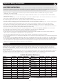 2
2
-
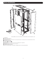 3
3
-
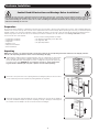 4
4
-
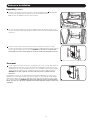 5
5
-
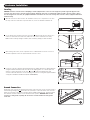 6
6
-
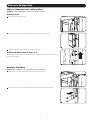 7
7
-
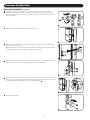 8
8
-
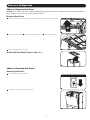 9
9
-
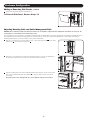 10
10
-
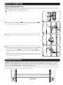 11
11
-
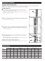 12
12
-
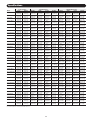 13
13
-
 14
14
-
 15
15
-
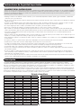 16
16
-
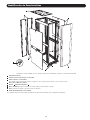 17
17
-
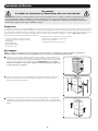 18
18
-
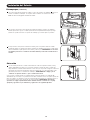 19
19
-
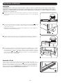 20
20
-
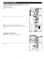 21
21
-
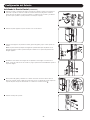 22
22
-
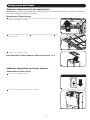 23
23
-
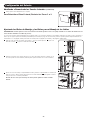 24
24
-
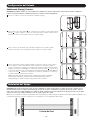 25
25
-
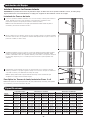 26
26
-
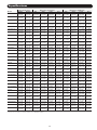 27
27
-
 28
28
-
 29
29
-
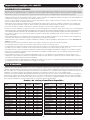 30
30
-
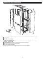 31
31
-
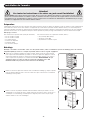 32
32
-
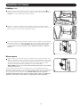 33
33
-
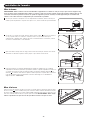 34
34
-
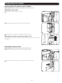 35
35
-
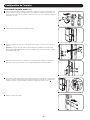 36
36
-
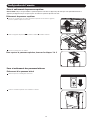 37
37
-
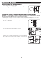 38
38
-
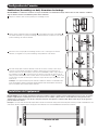 39
39
-
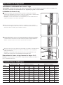 40
40
-
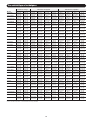 41
41
-
 42
42
-
 43
43
-
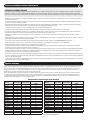 44
44
-
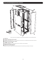 45
45
-
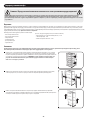 46
46
-
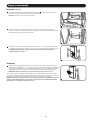 47
47
-
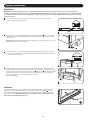 48
48
-
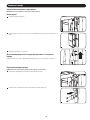 49
49
-
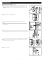 50
50
-
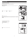 51
51
-
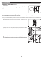 52
52
-
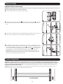 53
53
-
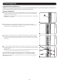 54
54
-
 55
55
-
 56
56


Tripp Lite Smart Rack Enclosures El manual del propietario
- Tipo
- El manual del propietario
en otros idiomas
Artículos relacionados
-
Tripp Lite Smart Rack Enclosures El manual del propietario
-
-
-
-
-
Tripp Lite Smart Rack Enclosures El manual del propietario
-
-
-
Tripp Lite SR42UBCL & SR48UBCL Rack Enclosures El manual del propietario
-
Tripp Lite SmartRack SR48UBCL El manual del propietario