Veranda 131171 Instrucciones de operación
- Tipo
- Instrucciones de operación

©2016 Universal Forest Products, Inc. All rights reserved.
68956 U.S. Hwy 131, White Pigeon, MI 49099 855.556.1852 8720_2/16
www.ufpi.com
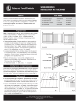
Check local ordinances and regulations before building your
fence. Before construction, contact your local utility companies
to mark any underground cables and pipelines. In addition, it is
a good idea to discuss plans with any neighbors along your
proposed fence line.
Note: These instructions are for fence installations using bracket
model number 131171 and 146238 with panel model number
118839, 141393, 153149 and 153152. If installing with the
Slidelock
™
bracket, refer to installation instructions provided
with the Slidelock bracket.
• Determine the number of posts, panels and gates needed to
complete the job based on the total linear footage. Take into
consideration post, panel and gate widths when determining
the total number of each. Adjust layout to accommodate as
many full panels as possible. If you must use a partial panel,
place it in the farthest rear corner of the property.
• Locate property boundaries and drive stakes into the ground
at corners and ends of fence line, based on local municipality
regulations. Stretch twine or heavy string between stakes and
pull tight to mark layout of fence line.
• Be sure to measure your fence panels and gates prior to
determining the location of the postholes. Place posts in the
following order along string line:
• End/corner posts • Gate posts • Line posts
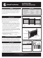
Most yards are relatively level and will allow for a simple installation.
If your yard is steeply pitched or uneven, be sure to allow for the
required mounting height of the adjacent panel when setting posts.
You may need to "stair step" the panels in extreme cases (fig. 1).
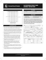
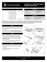
• Lay all components on a flat surface. Beginning with the starter
picket, lay all pickets facing the same direction and connect them
so that each tongue fits into an adjacent picket's groove (fig. 2).
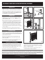
• Lay two horizontal rails across the pickets so the tongues on the
rails line up with the grooves in the pickets. Using a non-marring
rubber mallet, tap the horizontal rails locking the tongues of the
rails into the grooves in the pickets (fig. 3). Carefully flip the panel
over and install remaining horizontal rails in the same manner.
Slide the top rail along the groove at the top of the pickets so
that it is flush on both ends (fig. 4).
Installing fences on sloped landscapes
Items needed
• Posthole digger
• Tape measure
• Clear PVC cement
• Power drill
• Screwdriver
• Level
• Chop saw
• String line
• Concrete
• Gravel
• Shims
• Pencil
Design and layout
Fig.1.pdf
Step method
Post Cap
Post Post
Starter Picket
End
Picket
Pickets
Horizontal Rails
Fig.2.pdf
fig. 2
6x6 PRIVACY FENCE
INSTALLATION INSTRUCTIONS
Panel assembly
fig. 1
Fig.3.pdf
fig. 3
7811.pdf
fig. 4
Planning

2" Block
Fig.8.pdf
6x6 PRIVACY FENCE INSTALLATION INSTRUCTIONS, CONTINUED
©2016 Universal Forest Products, Inc. All rights reserved.
68956 U.S. Hwy 131, White Pigeon, MI 49099 855.556.1852 8720_2/16
www.ufpi.com
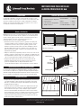
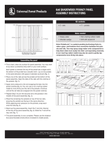
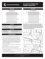
• Dig postholes 10" to 12" in diameter and 36" to 42" deep (depend-
ing on local ordinance or expected frost depth in winter) (fig. 5).
• Space posts according to the width of the fence (68") plus 1/4"
to accommodate the fence brackets. Use a string line to ensure
that all postholes are in line and verify spacing between holes
(fig. 6). Double-check all measurements.
• Starting with a corner, insert a post into the hole. Level and
adjust the height as needed using gravel. DO NOT place posts
permanently at this point.
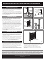
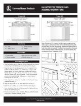
• Mix concrete per the instructions on the bag. Fill the posthole
and tap the post to the proper depth. Measure to be sure you
can install the finished panel to the post with approximately a
2" gap from the ground to the bottom of the panel. You will also
need to leave a space from the highest point of the panel to
the top of the post. The location of the post caps in relation to
the top of the panel is based on preference but we recommend
1-1/2" to 2" (fig. 7).
• Use a level to ensure the post is plumb and square with the
ground. Brace the post to hold the position as the concrete sets.
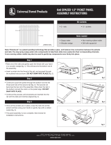
• Measure 13.5" + the necessary clearance at the bottom of the
panel (recommended height of 2") from the ground up and mark
the post. Install the fence bracket to the post with the bottom of
bracket flush with the mark.
• Measure from the bottom of the lower horizontal rail to the
bottom of the middle rail; this is the location of the second
bracket on the post.
• Place the brackets on the post. Use 4 of the provided screws to
mount each bracket. DO NOT OVERTIGHTEN (fig. 8).
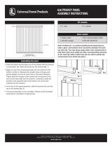
• Set the panel into the brackets on the first preset post. Repeat
steps above to install the brackets on the next post. Place this
post (at the opposite end of the panel without any concrete in
the hole. Ensure the posts are against the panel and secure all
screws in the center of the bracket slots (fig. 9).
• Use a level to ensure the fence is plumb and the posts are
Digging postholes
fig. 4
THE DIAGRAMS AND INSTRUCTIONS IN THIS BROCHURE ARE FOR ILLUSTRATION PURPOSES ONLY AND ARE NOT MEANT TO REPLACE A LICENSED PROFESSIONAL. ANY CONSTRUCTION OR
USE OF THE PRODUCT MUST BE IN ACCORDANCE WITH ALL LOCAL ZONING AND/OR BUILDING CODES. THE CONSUMER ASSUMES ALL RISKS AND LIABILITY ASSOCIATED WITH THE
CONSTRUCTION OR USE OF THIS PRODUCT. THE CONSUMER OR CONTRACTOR SHOULD TAKE ALL NECESSARY STEPS TO ENSURE THE SAFETY OF EVERYONE INVOLVED IN THE PROJECT,
INCLUDING, BUT NOT LIMITED TO, WEARING THE APPROPRIATE SAFETY EQUIPMENT. EXCEPT AS CONTAINED IN THE WRITTEN LIMITED WARRANTY, THE WARRANTOR DOES NOT
PROVIDE ANY OTHER WARRANTY, EITHER EXPRESS OR IMPLIED, AND SHALL NOT BE LIABLE FOR ANY DAMAGES, INCLUDING CONSEQUENTIAL DAMAGES.
square with the ground. Brace the panel and post to hold the
position as the concrete sets (per manufacturer's recommen-
dations for curing time). Continue setting posts and installing
panels to complete the project.
• Install a post cap on each post using clear PVC cement or
an exterior adhesive to finish your project.
68-1/2" from
Post to Post
Corner or End Post
Level
Fig.5.pdf
Middle
Rail
Lower
Horizontal
Rail
1-1/2"
2"
Fig.6.ai
fig. 6
fig. 7
Setting first post
Fig.7.pdf
fig. 9
Rail bracket location
fig. 4
36" to 42"
10" to 12"
Diameter
Level
Fig.4.pdf
fig. 5
Installing panels and remaining posts
fig. 8

©2016 Universal Forest Products, Inc. Todos los derechos reservados.
68956 U.S. Hwy 131, White Pigeon, MI 49099 855.556.1852 8720_2/16
www.ufpi.com
Compruebe ordenanzas y normas locales antes de construir su cerca.
Antes de la construcción, póngase en contacto con las empresas locales
de servicios públicos para marcar los cables subterráneos y tuberías.
Además, es una buena idea hablar sobre estos planes con los vecinos
a lo largo de su línea de cerca propuesta.
Nota: Estas instrucciones son para instalaciones de cercas que utilizan
el modelo de soporte número 131171 y 146238 con el modelo de panel
número 118839, 141393, 153149 y 153152. Si instala los paneles con el
soporte Slidelock
™
, por favor, consulte las instrucciones de
instalación que vienen con el soporte Slidelock.
• Determine el número de postes, paneles y puertas necesarias para
completar el trabajo en base al total de los metros lineales. Tome en
consideración los anchos de los postes, paneles y puertas cundo
determine el número total de cada uno de ellos. Modifique el diseño
para dar cabida a tantos paneles completos como sea posible. Si
debe usar parte de un panel, colóquelo en la esquina posterior más
alejada de la propiedad.
• Ubique los límites de la propiedad y meta las estacas en el suelo en las
esquinas y extremos de línea de la cerca, siguiendo los reglamentos de
la municipalidad local. Estire el hilo o el cordel pesado entre las estacas
y tire con fuerza para marcar el diseño de la línea de la cerca.
• Asegúrese de medir los paneles de la cerca y las puertas antes de
determinar la ubicación de los huecos para los postes. Coloque los
postes en el siguiente orden a lo largo de la línea del cordel:
• Postes del extremo/esquina • Postes de la puerta • Postes de línea
La mayoría de los jardines son relativamente planos y permiten una insta-
lación sencilla. Si su jardín es muy empinado o desigual, asegúrese de dejar la
altura de montaje deseado para el panel adyacente cuando coloque los postes.
En casos extremos es posible que necesite "escalonar" los paneles (fig. 1).
• Ponga todos los componentes sobre una superficie plana. Comenzando
con el primer piquete, o tabla, ponga todos los piquetes en la misma
dirección y conéctelos de modo que cada lengua encaje en la ranura
del piquete adyacente (Fig. 2).
• Ponga dos listones horizontales a través de los piquetes de modo que
las lenguas de los listones se alineen con las ranuras de los piquetes.
Con un mazo de caucho que no raspe, dé ligeros golpes sobre los
listones horizontales fijando las lenguas de los listones en las ranuras
de los piquetes (fig. 3). Voltee con cuidado el panel e instale los restantes
listones horizontales de la misma manera. Deslice el listón superior a
lo largo de la ranura en la parte superior de los piquetes de modo que
quede a ras en ambos extremos (fig. 4).
Instalación de cercas en jardines inclinados
Artículos que se necesitan
• Cavador de hoyos de poste
• Cinta métrica
• Cemento PVC transparente
• Taladro eléctrico
• Destornillador
• Nivel
• Sierra caladora
• Cuerda alineadora
• Concreto
• Grava
• Cuñas
• Lápiz
Diseño y distribución
Fig.1.pdf
Método de escalonamiento
Tapa del poste
Poste
Poste
Primer piquete
Ultimo
piquete
Piquetes
Listones
horizontales
Fig.2.pdf
fig. 2
INSTRUCCIONES PARA INSTALAR
LA CERCA PRIVACIDAD DE 6x6
Ensamble del panel
fig. 1
Fig.3.pdf
fig. 3
7811.pdf
fig. 4
Planificación

Bloque de 2 pulgadas
Fig.8.pdf
INSTRUCCIONES PARA INSTALAR LA CERCA PRIVACIDAD DE 6x6 CONTINUACIÓN
©2016 Universal Forest Products, Inc. Todos los derechos reservados.
68956 U.S. Hwy 131, White Pigeon, MI 49099 855.556.1852 8720_2/16
www.ufpi.com
• Cave huecos de 10 a 12 pulgadas de diámetro y de 36 a 42 pulgadas de
profundidad (dependiendo de la ordenanza local o de la profundidad de
helada que se espera en el invierno) (Fig. 5).
• Espacie los postes de acuerdo al ancho de la cerca (68 pulgadas) más
¼ de pulgada para acomodar los soportes de la cerca. Utilice una línea
de cordel para asegurarse que todos los huecos para los postes estén
en línea y verifique el espaciado entre los huecos (Fig. 6). Verifique dos
veces todas las mediciones.
• Comenzando en una esquina, meta un poste en el hueco. Nivele y
ajuste la altura según sea necesario con grava. NO ponga los postes
en forma permanente por ahora.
• Mezcle el hormigón de acuerdo a las instrucciones en la bolsa. Llene
el hueco del poste y dé golpecitos sobre el poste hasta conseguir
la profundidad adecuada. Mida para asegurarse de que puede aún
instalar el panel acabado al poste con una brecha de aproximadamente
2 pulgadas desde el suelo hasta la parte inferior del panel. También
debe dejar un espacio desde el punto más alto del panel hasta la parte
superior del poste. La ubicación de las tapas del poste en relación
con la parte superior del panel depende de su preferencia pero
recomendamos de 1-1/2 a 2 pulgadas (fig. 7).
• Utilice un nivel para asegurarse que el poste esté a plomo y escuadra
con el suelo. Afiance el poste para que sostenga su posición mientras
se seca el hormigón.
• Mida 13,5 pulgadas + el espacio libre necesario en la parte inferior del
panel (altura recomenda de 2 pulgadas) desde el suelo y marque el
poste. Instale el soporte de la cerca al poste con la parte inferior del
soporte a ras con la marca.
• Mida desde la parte inferior del listón horizontal inferior a la parte inferior
del listón del medio; este es el lugar del segundo soporte en el poste.
• Coloque los soportes en el poste. Utilice 4 de los tornillos provistos para
montar cada soporte. NO LOS APRIETE DEMASIADO (fig. 8).
• Fije el panel en los soportes del primer poste ya puesto. Repita los
pasos anteriores para instalar los soportes en el próximo poste. Ponga
este poste (en el extremo opuesto del panel sin hormigón en el hueco.
Asegúrese de que los postes estén contra el panel y asegure todos los
tornillos en el centro de las ranuras del soporte (fig. 9).
• Utilice un nivel para asegurarse que la cerca esté a plomo y escuadra
con el suelo. Afiance el panel y el poste para que sostengan su posición
Cómo cavar huecos para los postes
fig. 4
LOS DIAGRAMAS E INSTRUCCIONES EN ESTE FOLLETO TIENEN SOLO FINES ILUSTRATIVOS Y NO PRETENDEN REEMPLAZAR A UN PROFESIONAL CON LICENCIA. CUALQUIER CONSTRUCCIÓN
O USO DE ESTE PRODUCTO DEBE ESTAR EN CONFORMIDAD CON TODOS LOS CÓDIGOS LOCALES DE ZONIFICACIÓN Y/O CONSTRUCCIÓN. EL CONSUMIDOR ASUME TODOS LOS RIESGOS Y
RESPONSABILIDADES ASOCIADOS A LA CONSTRUCCIÓN O EL USO DE ESTE PRODUCTO. EL CLIENTE O EL CONTRATISTA DEBE TOMAR TODAS LAS MEDIDAS NECESARIAS PARA GARANTIZAR
LA SEGURIDAD DE TODOS LOS INVOLUCRADOS EN EL PROYECTO -INCLUYENDO PERO NO LIMITADO A- EL USO EL EQUIPO DE SEGURIDAD APROPIADO. SALVO LO EXPRESADO EN LA GARANTÍA
LIMITADA POR ESCRITO, EL GARANTE NO OFRECE NINGUNA OTRA GARANTÍA, EXPLÍCITA O IMPLÍCITA, Y NO SERÁ RESPONSABLE POR NINGÚN DAÑO, INCLUSO LOS INDIRECTOS.
mientras seca el hormigón (según las recomendaciones del
fabricante para el tiempo de curado). Continúe poniendo los postes
e instalando los paneles para completar el proyecto.
• Coloque una tapa de poste en cada poste utilizando cemento
PVC transparente o un adhesivo para uso exterior para terminar
su proyecto.
68-1/2 pulgadas de
poste a poste
Poste de la esquina
o del extremo
Nivel
Fig.5.pdf
Listón del
medio
Listón
horizontal
de la parte
inferior
1-1/2 pulgadas
2 pulgadas
Fig.6.ai
fig. 6
fig. 7
Colocación del primer poste
Fig.7.pdf
fig. 9
Ubicación del soporte del listón
fig. 4
36 a 42
pulgadas
10 a 12
pulgadas de
diámetro.
Nivel
Fig.4.pdf
fig. 5
Instalación de los paneles y de los postes restantes
fig. 8
-
 1
1
-
 2
2
-
 3
3
-
 4
4


Veranda 131171 Instrucciones de operación
- Tipo
- Instrucciones de operación
en otros idiomas
Artículos relacionados
-
 Veranda 131171 Guía de instalación
-
 Veranda 153149 Guía de instalación
-
 Veranda 116059 Instrucciones de operación
-
 Veranda 128013 Guía de instalación
-
 Veranda 128008 Guía de instalación
-
 Veranda 306114 Instrucciones de operación
-
 Veranda 128011 Guía de instalación
-
 Veranda 128011 Instrucciones de operación
-
 Veranda 128009 Instrucciones de operación
-
Veranda 128011 Guía de instalación


