
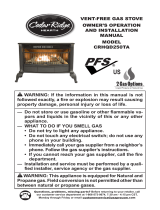
Questions, problems, missing parts? Before returning to your retailer, call
our customer service department at 1-866-573-0674, 7:30 am - 4:15 pm CST,
Monday through Friday or email [email protected]
NVDWA2
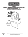
MANUAL ON/OFF VALVE
SAFETY PILOT KIT
INSTALLATION INSTRUCTIONS
Spanish/Español
Page 11
Bafe Panel for
Use With Glass
Burners Only

www.usaprocom.com
200279-01A2
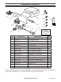
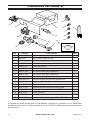
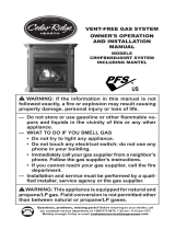
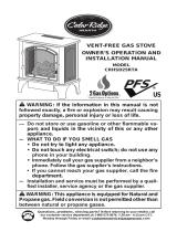
PACKAGE CONTENTS
If any of these pieces are missing or damaged, contact the dealer where you purchased this
kit or ProCom Heating, Inc. at 1-866-573-0674 for referral information.
Item Part Number Description Qty
1 WAL06-02 Propane/LP Burner Air Mixer 1
2 NV2050 Gas Control Valve 1
3 NDW-N600X4 Safety Pilot 1
4 WAB09 Pilot Gas Pipe Assembly 1
5 WAL52-01 Control Knob 1
6 WAL57-01 Control Rod Extension 1
7 WAL07-04L 18" Propane/LP Orice 1
8 WAL07-05L 24" Propane/LP Orice 1
9 WAL07-06L 30" Propane/LP Orice 1
10 NDW0811-LP Propane/LP Pilot Injector 1
11 WAL43-02 Valve Cover 1
12 ML083-02 Piezo Ignitor 1
13 WAL17-02 Control Instructions Label 1
14 WAL08-03A Elbow Fitting, 3/8" x 3/8" NPT 1
15 WAL43-03 Bafe Panel 1
16 RN0604B Regulator 1
17 WAL08-03 Gas Inlet Fitting, 3/8" NPT x Flare 1
OFF ON
PILOT
When control kit is
on the left of the burner
pan, use this label.
5
6
2
14
12
11
7
8
9
17
13
10
4
1
15
3
16

www.usaprocom.com
3200279-01A
SAFETY
IMPORTANT: Read all instruc-
tions and warnings carefully
before starting installation. Fail-
ure to follow these instructions
may result in a possible electric
shock, re hazard and will void
the warranty.
WARNING: If the information
in this manual is not followed
exactly, a re or explosion may
result causing property damage,
personal injury, or loss of life.
WARNING: Improper installa-
tion, adjustment, alteration, ser-
vice, or maintenance can cause
injury or property damage. Refer
to this manual for correct installa-
tion and operational procedures.
For assistance or additional infor-
mation consult a qualied installer,
service agency, or the gas supplier.
WARNING: This appliance
requires a 1/2" NPT (National
Pipe Thread) inlet connection to
the pressure regulator.
WARNING: A qualied service
person must connect log set to
gas supply. Follow all local codes.
WARNING: Never connect
natural gas appliance to private
(non-utility) gas wells. This gas is
commonly known as wellhead gas.
WARNING: Use pipe joint
sealant that is resistant to liquid
petroleum (LP) gas.
WARNING: Test all gas piping
and connections for leaks after
installing or servicing. Correct
all leaks at once.
WARNING: Never use an open
ame to check for a leak. Apply a
noncorrosive leak detection uid
to all joints. Bubbles forming show
a leak. Correct all leaks at once.
WARNING: You must use a
ON/OFF safety valve/pilot kit for
propane/LP conversion.
CAUTION: Never connect pro-
pane/LP appliance directly to the
propane/LP supply. This appliance
requires an external regula-
tor (not supplied). Install the
external regulator between the
appliance and propane/LP supply.
CAUTION: Use only new, black
iron or steel pipe. Internally-tinned
copper tubing may be used in
certain areas. Check your local
codes. Use pipe of 1/2" diam-
eter or greater to allow proper gas
volume to log set. If pipe is too small,
undue loss of volume will occur.
CAUTION: For additional
convenience and safety, this ON/
OFF Valve/Safety Pilot Kit can be
used with natural gas as well.
If you are unsure of the proper
application, call our customer
service at 866-573-0674 for fur-
ther information.
CAUTION: If the replace does
not have a gas supply shutoff
valve, one must be installed.
WARNING: This product
contains and/or generates
chemicals known to the State
of California to cause cancer or
birth defects or other reproduc-
tive harm.

www.usaprocom.com
200279-01A4
PREPARATION
Before beginning assembly of product, make sure all parts are present. Compare parts with
package contents list. If any part is missing or damaged, do not attempt to assemble the
product. Contact customer service for replacement parts.
Estimated Assembly Time: 60 minutes
Tools Required for Assembly (not included): Phillips Screwdriver, Pipe Sealant, Adjustable
Wrench Sediment Trap and Manual Shutoff Valve.
Helpful Tools (not included): 10 mm Socket or Nut Driver.
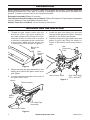
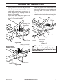
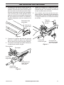
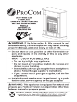
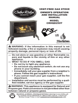
Figure 1
Figure 2
Figure 3
Gas
Connector
Tube
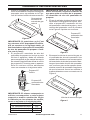
NATURAL GAS INSTALLATION
2. Attach the pilot gas pipe assembly to the
safety pilot outlet of the gas control valve
and tighten.
3. Connect the thermocouple to the rear of
the gas control valve.
Gas Control Valve
Gas Control Valve
Gas
Control
Valve
Safety
Pilot
Thermocouple
Burner Air
Mixer
Ignitor
Pilot Gas Pipe
Assembly
Gas Inlet Fitting
3/8" x 3/8" NPT
1. Thread the gas control valve onto the
burner air mixer. Use pipe sealant on
the male threads of the burner air mixer.
Hold the burner air mixer with a wrench
to prevent overtightening the connection
to the burner. Make sure the control rod
is facing the front as shown in Figure 1.
4. Install the gas inlet tting into the inlet
opening of the gas control valve. Use pipe
sealant on the male pipe threads.
5. Carefully shape the gas supply tube and
attach to gas inlet fitting as shown in
Figure 3. Be careful not to cause kinks in
tube.

www.usaprocom.com
5200279-01A
NATURAL GAS INSTALLATION
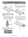
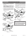
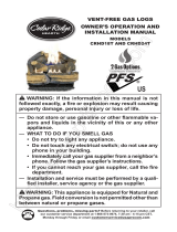
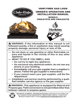
Figure 5
Figure 4A
Figure 4B
Valve Cover
Valve Cover
Bafe Panel
Control
Knob
Control Rod
Extension
Ignitor
Cable
Control Rod
Ignitor
Safety Pilot
and Ignitor
Assembly
Safety Pilot and
Ignitor Assembly
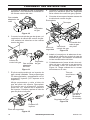
Place the burner pan assem-
bly in the center of the replace
oor. Make sure the front of pan
faces forward.
6. Install valve cover to burner pan using self
tapping screws as shown in Figure 4A.
FOR GLASS BURNER MODELS ONLY
Install bafe panel and valve cover to
burner pan using self tapping screws as
shown in Figure 4B.
7. Install safety pilot and piezo ignitor onto
bafe panel using self tapping screws as
shown in Figure 4A and 4B.
8. Install the control knob to the control rod
extension. Push the control rod extension
onto the “D” shaped control rod through
the center hole in the cover as shown in
Figure 5.
9. Install the piezo ignitor through hole in the
valve cover. Attach ignitor cable to ignitor.
Glass Burner
Models Only

www.usaprocom.com
200279-01A6
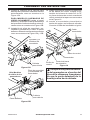
PROPANE/LP GAS INSTALLATION
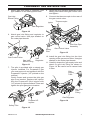
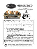
1. Remove the natural gas burner inlet tting
from the burner pan assembly as shown
in Figure 6. DO NOT remove the orice
from this tting.
IMPORTANT: For an 18" or 30" log set, use
a 10 mm socket or nut driver to remove
the orice from the propane/LP burner
air mixer.
3. Using pipe sealant on the thread of the
larger end of tting, screw the propane/
LP burner air mixer through hole and into
burner manifold as shown in Figure 8.
Tighten using a wrench.
Figure 6
Figure 7
Figure 8
Burner Inlet
Fitting for
Natural Gas
IMPORTANT: If you have a 24" log set,
then the 24" propane/LP orice, shown
in the table below, is already installed in
the propane/LP burner air mixer. Proceed
to step 3.
2. The propane/LP burner air mixer included
in this kit has 6 holes and must be used to
replace the natural gas inlet tting. Be sure
to use the correct propane/LP orice for
your appliance. This kit contains additional
orices as shown in the table below.
IMPORTANT: The number stamped on ori-
ces correspond to each respective size
log set as indicated by model numbers as
shown in table below.
Model # Orice #
18" Vented Logs 205
24" Vented Logs 225
30" Vented Logs 242
Figure 9
Gas Control Valve
Propane/LP
Burner Air
Mixer
Propane/LP
Burner Air
Mixer
Propane/LP
Orice
4. Thread the gas control valve onto the
burner air mixer. Use pipe sealant on
the male threads of the burner air mixer.
Hold the burner air mixer with a wrench
to prevent overtightening the connection
to the burner. Make sure the control rod
is facing the front as shown in Figure 9.

www.usaprocom.com
7200279-01A
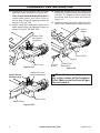
Gas Inlet
Elbow Fitting
Gas Inlet
Elbow Fitting
Figure 10
Figure 11
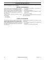
Figure 13
8. Attach the pilot gas pipe assembly to the
safety pilot outlet of the gas control valve
and tighten.
9. Connect the thermocouple to the rear of
the gas control valve.
Gas Control Valve
Gas Control Valve
Safety
Pilot
Safety Pilot
Thermocouple
Ignitor
Pilot Gas Pipe
Assembly
Gas Regulator
Propane/LP
Injector
Gas
Regulator
PROPANE/LP GAS INSTALLATION
5. Attach gas inlet tting to regulator. Use
pipe sealant on the male pipe threads.
6. Attach gas inlet tting and regulator to
gas control valve. Use pipe sealant on
the male pipe threads.
Figure 12
7. The pilot is provided with a natural gas
injector installed. For Propane/LP gas
you must remove it and replace it with the
Propane/LP injector (“LP” printed on the
surface).
Gently loosen and remove the pilot gas
pipe from bracket. Replace the injector
with the Propane/LP pilot injector with
“LP” printed on injector surface. Place and
tighten the pilot gas pipe to bracket.
Figure 14
Gas
Supply
Tube
Gas Inlet
Flare
Fitting
10. Install the gas inlet tting into the inlet
opening of the gas control valve. Use pipe
sealant on the male pipe threads.
11. Carefully shape the gas supply tube and
attach to gas inlet fitting as shown in
Figure 14. Be careful not to cause kinks
in tube.
Gas Regulator

www.usaprocom.com
200279-01A8
PROPANE/LP GAS INSTALLATION
Figure 16
Control
Knob
Control Rod
Extension
Ignitor
Cable
Control Rod
Ignitor
Place the burner pan assem-
bly in the center of the replace
oor. Make sure the front of pan
faces forward.
14. Install the control knob to the control rod
extension. Push the control rod extension
onto the “D” shaped control rod through
the center hole in the cover as shown in
Figure 16.
15. Install the piezo ignitor through hole in the
valve cover. Attach ignitor cable to ignitor.
Figure 15A
Valve Cover
Safety Pilot
and Ignitor
Assembly
12. Install valve cover to burner pan using self
tapping screws as shown in Figure 15A.
FOR GLASS BURNER MODELS ONLY
Install bafe panel and valve cover to
burner pan using self tapping screws as
shown in Figure 15B.
13. Install safety pilot and piezo ignitor onto
bafe panel using self tapping screws as
shown in Figure 15A and 15B.
Figure 15B
Valve Cover
Bafe Panel
Safety Pilot and
Ignitor Assembly
Glass Burner
Models Only

www.usaprocom.com
9200279-01A
REPLACEMENT PARTS
Note: Use only original replacement parts. This will protect your warranty coverage for parts
replaced under warranty.
PARTS UNDER WARRANTY
Contact authorized dealers of this product.
If they can’t supply original replacement
parts, call Customer Service toll free at
1-866-573-0674 for referral information.
When calling Customer Service or your dealer,
have ready:
• Your name
• Your address
• Model and serial number of your heater
• How heater was malfunctioning
• Type of gas used (Propane/LP or Natural
gas/NG)
• Purchase date
Usually, we will ask you to return the defective
part to the factory
PARTS NOT UNDER WARRANTY
Contact authorized dealers of this product.
If they can’t supply original replacement
part(s) call Customer Service toll free at
1-866-573-0674 for referral information.
When calling Customer Service have ready:
• Model number of your heater
• The replacement part number

200279-01
Rev. A
09/15
WARRANTY
KEEP THIS WARRANTY
Model _______________________________
Serial No. ____________________________
Date Purchased _______________________
Keep receipt for warranty verication.
REGISTER YOUR PRODUCT AT WWW.USAPROCOM.COM
IMPORTANT: We urge you to register your product within 10 days of date of installation, complete
with entire serial number which can be found on the rating plate. Please ll out the warranty infor-
mation above for your personal records. Retain this manual for future reference.
Always specify model and serial numbers when communicating with customer service.
We reserve the right to amend these specications at any time without notice. The only warranty applicable
is our standard written warranty. We make no other warranty, expressed or implied.
LIMITED WARRANTY
ProCom Heating, Inc. warrants this product to be free from defects in materials and components for ONE
(1) year from the date of rst purchase, provided that the product has been properly installed by a qualied
installer in accordance with all local codes and instructions furnished with the unit, operated and main-
tained in accordance with all applicable instructions. To make a claim under this warranty, the Bill of Sale
or cancelled check must be presented.
RESPONSIBILITY OF OWNER
This warranty is extended only to the original retail purchaser. This warranty covers the cost of part(s)
required to restore this heater to proper operating condition. Warranty part(s) MUST be obtained through
ProCom Heating, Inc. who will provide original factory replacement parts. Failure to use original factory
replacement parts voids this warranty.
IMPORTANT: The heater MUST be installed by a qualied installer in accordance with all local codes
and instructions furnished with the unit or the warranty is voided.
WHAT IS NOT COVERED
This warranty does not apply to parts that are not in original condition because of normal wear and tear or
parts that fail or become damaged as a result of misuse, accidents, lack of proper maintenance or defects
caused by improper installation. Travel, diagnostic cost, labor, transportation and any and all such other
costs related to repairing a defective heater will be the responsibility of the owner.
TO THE FULL EXTENT ALLOWED BY THE LAW OF THE JURISDICTION THAT GOVERNS THE SALE
OF THE PRODUCT, THIS EXPRESS WARRANTY EXCLUDES ANY AND ALL OTHER EXPRESSED
WARRANTIES AND LIMITS THE DURATION OF ANY AND ALL IMPLIED WARRANTIES. INCLUDING
WARRANTIES OF MERCHANTABILITY AND FITNESS FOR A PARTICULAR PURPOSE TO ONE (1)
YEAR ON ALL COMPONENTS FROM THE DATE OF FIRST PURCHASE. PROCOM HEATING, INC.'S
LIABILITY IS HEREBY LIMITED TO THE PURCHASE PRICE OF THE PRODUCT AND PROCOM HEAT-
ING, INC. SHALL NOT BE LIABLE FOR ANY OTHER DAMAGES WHATSOEVER INCLUDING INDIRECT.
INCIDENTAL OR CONSEQUENTIAL DAMAGES.
Some states do not allow a limitation on how long an implied warranty lasts or an exclusion or limitation of
accidental or consequential damages, the above limitation on implied warranties, or exclusion or limitation
on damages may not apply to you.
This warranty gives you specic legal right, and you may also have other rights that vary from state to state.
ProCom Heating, Inc.
Bowling Green, KY 42101
www.usaprocom.com
1-866-573-0674

NVDWA2
MANUAL DE ENCENDIDO/APAGADO VÁLVULA
PILOTO SEGURIDAD DE KIT
INSTRUCCIONES DE INSTALACIÓN
El deector panel
para uso con
vidrio quemadores
solamente
¿Preguntas, problemas, piezas faltantes? Antes de volver a la tienda, llame a
nuestro Departamento de Servicio al Cliente al 1-866-573-0674, de lunes a viernes de
7:30 a.m. a 4:15 p.m., Hora del Centro, o envíe un correo electrónico a
customerser[email protected].

www.usaprocom.com
200279-01A12
CONTENIDOS DEL PAQUETE
Si alguna de estas piezas falta o está dañado, póngase en contacto con el distribuidor
donde adquirió este kit o ProCom Heating, Inc. al 1-866-573-0674 para obtener información
de referencia.
Art.
Pieza # Descripción
Cant.
1 WAL06-02 Propano/LP Quemador Aire Mezclador 1
2 NV2050 Válvula de control del gas 1
3 NDW-N600X4 Piloto de seguridad 1
4 WAB09 Ensamble del tubo de gas del piloto 1
5 WAL52-01 Perilla de control 1
6 WAL57-01 Control de barra de extensión 1
7 WAL07-04L 18" Oricio para gas propano/LP 1
8 WAL07-05L 24" Oricio para gas propano/LP 1
9 WAL07-06L 30" Oricio para gas propano/LP 1
10 NDW0811-LP Inyector de gas del piloto de propano/LP 1
11 WAL43-02 Cubierta para válvula 1
12 ML083-02 Encendedor piezoeléctrico 1
13 WAL17-02 Etiqueta de las instrucciones de control 1
14 WAL08-03A Adaptador del codo, 3/8" x 3/8" NPT 1
15 WAL43-03 Panel deector 1
16 RN0604B Regulador 1
17 WAL08-03 Conector de entrada de gas, 3/8" NPT x Flare 1
OFF ON
PILOT
When control kit is
on the left of the burner
pan, use this label.
5
6
2
14
12
11
7
8
9
17
13
10
4
1
15
3
16

www.usaprocom.com
13200279-01A
SEGURIDAD
IMPORTANTE: Lea todas las
instrucciones y advertencias
antes de comenzar la instala-
ción. El incumplimiento de estas
instrucciones puede resultar en
una posible descarga eléctrica,
peligro de incendio y se anulará
la garantía.
ADVERTENCIA: Si no se sigue
con precisión la información de
este manual, pueden provocarse
incendios o explosiones que
produzcan daños a la propiedad,
lesiones personales o la muerte.
ADVERTENCIA: La instala-
ción, el ajuste, la alteración, la
reparación o el mantenimiento
inadecuado pueden ocasionar
lesiones o daños a la propie-
dad. Consulte este manual para
conocer las instrucciones de
instalación y de funcionamien-
to. Si necesita ayuda o desea
información adicional, consulte
a un instalador calicado, una
empresa de servicio o el pro-
veedor de gas.
ADVERTENCIA: Este electro-
doméstico requiere una cone-
xión de entrada NPT (National
Pipe Thread) de 1/2" al regulador
de presión.
ADVERTENCIA: Una técni-
co calicado debe conectar el
juego de leños al suministro de
gas. Respete todos los códigos
locales.
ADVERTENCIA: No instale el
electrodoméstico de gas natural
en pozos de gas privados (que
no pertenezcan a los servicios
públicos). Este gas se conoce
comúnmente como gas de pozo.
ADVERTENCIA: Utilice un
sellador para juntas de tuberías
que sea resistente al gas líquido
de petróleo (PL).
ADVERTENCIA: Verifique
todas las tuberías y conexio-
nes de gas para detectar fugas
después de la instalación o el
mantenimiento. Repare todas
las fugas de inmediato.
ADVERTENCIA: No use nunca
una llama directa para detectar
fugas. Aplique un líquido antico-
rrosivo para detectar fugas en
todas las juntas. Si hay una fuga,
se formarán burbujas. Repare
todas las fugas de inmediato.
ADVERTENCIA: Debe usar
una válvula de seguridad de
encendido/apagado o un kit pi-
loto para la conversión de gas
propano/PL.
PRECAUCIÓN: Nunca co-
necte el electrodoméstico de
gas propano/PL directamente al
suministro de gas propano/PL.
Este electrodoméstico necesita
un regulador externo (no inclui-
do). Instale el regulador externo
entre el electrodoméstico y el
suministro de gas propano/PL.

www.usaprocom.com
200279-01A14
PREPARACIÓN
Antes de comenzar a ensamblar el producto, asegúrese de tener todas las piezas. Compare
las piezas con la lista del contenido del paquete. No intente ensamblar el producto si falta
alguna pieza o si éstas están dañadas. Póngase en contacto con el servicio al cliente para
obtener piezas de repuesto.
Tiempo estimado de ensamblaje: 60 minutos
Herramientas necesarias para el ensamblaje (no se incluyen): Destornillador Phillips,
sellador de tuberías, llave ajustable, trampa de sedimentos y válvula de cierre manual.
Herramientas útiles (no se incluyen): Llave para tuercas o de tubos de 10 mm.
SEGURIDAD
PRECAUCIÓN: Utilice sólo
tuberías nuevas de hierro negro
o acero. En algunas áreas, es
posible que se utilicen tuberías
de cobre con revestimiento
interno de estaño. Revise los
códigos locales. Utilice una
tubería de 1/2" de diámetro o
más para permitir la entrada de
un volumen adecuado de gas
al juego de leños. Si la tubería
es demasiado pequeña, habrá
pérdida de volumen indebida.
PRECAUCIÓN: Para lograr
comodidad y seguridad adicio-
nales, este kit piloto de válvula
de encendido/apagado puede
usarse también con gas natural.
Si tiene dudas sobre la aplica-
ción adecuada, llame a nuestro
Servicio al Cliente 866-573-0674
para obtener más información.
PRECAUCIÓN: Si la chimenea
no cuenta con una válvula de
cierre del suministro de gas, se
debe instalar una.
ADVERTENCIA: Este produc-
to contiene y/o genera químicos
que el Estado de California
reconoce que causan cáncer,
defectos de nacimiento u otros
daños relacionados con la re-
producción.

www.usaprocom.com
15200279-01A
Figura 1
Figura 2
Figura 3
Tubo de
conexión
de gas
INSTALACIÓN GAS NATURAL
2. Coloque el conjunto del tubo de gas del
piloto a la salida de piloto de seguridad
de la válvula de control de gas y apriete.
3. Conectar el termopar a la parte trasera de
la válvula de control de gas.
Válvula de
control del gas
Válvula de
control del gas
Válvula de
control del
gas
Piloto de
seguridad
Termopar
Quemador aire
mezclador
Encendedor
Ensamble del
tubo de gas
del piloto
Conector de
entrada de gas
3/8" x 3/8" NPT
1. Enrosque la válvula de control de gas en
el mezclador de aire del quemador. Use
sellador de tuberías en las roscas macho
del mezclador de aire del quemador. Man-
tenga el mezclador de aire del quemador
con una llave para evitar apretar dema-
siado la conexión al quemador. Asegúrese
de que la barra de control se enfrenta a
la parte delantera como se muestra en la
Figura 1.
4. Instale el montaje en la abertura de en-
trada de la válvula de control de gas de
entrada de gas. Use sellador de tuberías
en las roscas macho del tubo.
5. Con cuidado, dan forma al tubo de sumi-
nistro de gas y adjuntar a gas accesorio
de entrada, como se muestra en la Figura
3. Tenga cuidado de no causar torceduras
en el tubo.

www.usaprocom.com
200279-01A16
INSTALACIÓN GAS NATURAL
Figura 5
Figura 4A
Figura 4B
Cubierta
para válvula
Cubierta
para válvula
Panel deector
Perilla de
control
Control de barra
de extensión
Cable
encendedor
Barra de control
Encendedor
Piloto de
seguridad y la
asamblea del
encendedor
Piloto de seguridad
y la asamblea del
encendedor
Coloque el conjunto de bande-
ja del quemador en el centro del
piso de la chimenea. Asegúrese
de que la parte delantera de la
bandeja mira hacia delante.
6. Instale la cubierta de la válvula para
bandeja del quemador mediante tornillos
autorroscantes como se muestra en la
Figura 4A.
PARA MODELOS QUEMADOR DE
VIDRIO SOLAMENTE Instale el panel
deector y la tapa de la válvula de bandeja
del quemador mediante tornillos autorros-
cantes como se muestra en la Figura 4B.
7. Instale piloto de seguridad y encendedor
piezoeléctrico sobre el panel deector con
tornillos autorroscantes como se muestra
en la Figura 4A y 4B.
8. Instale la perilla de control a la extensión
de las barras de control. Empuje la ex-
tensión de la barra de control en la "D"
en forma de barra de control a través del
oricio central de la tapa como se muestra
en la Figura 5.
9. Instale el encendedor piezoeléctrico
través del agujero en la tapa de válvulas.
Conecte el cable del encendido a ignitor.
Sólo Modelos
de vidrio de los
quemadores

www.usaprocom.com
17200279-01A
PROPANO/LP INSTALACIÓN DE GAS
1. Retire el quemador de gas natural acce-
sorio de entrada del conjunto bandeja del
quemador como se muestra en la Figu-
ra 6. NO retire el oricio de este accesorio.
IMPORTANTE: Para un 18 "o 30" set log,
utilice un enchufe o la tuerca conductor 10
mm para quitar el oricio de la propano/
LP mezclador de aire del quemador de
propano.
3. El uso de sellador de tuberías en la rosca
del extremo más grande del ajuste, ator-
nillar el propano/LP mezclador de aire
del quemador a través del agujero y en el
colector del quemador como se muestra
en la Figura 8. Apriete con una llave.
Figura 6
Figura 7
Figura 8
Quemadores
accesorio de
entrada de gas
natural
IMPORTANTE: Si usted tiene un 24 "set
log, entonces el 24" de propano/LP oricio,
que se muestra en la siguiente tabla, ya
está instalado en el propano/LP mezclador
de aire del quemador de propano. Conti-
núe con el paso 3.
2. El propano/LP mezclador de aire del
quemador de propano se incluye en este
kit tiene 6 agujeros y debe ser utilizado
para reemplazar el gas natural accesorio
de entrada. Asegúrese de utilizar el oricio
de propano/LP correcto para su aparato.
Este kit contiene orificios adicionales
como se muestra en la siguiente tabla.
IMPORTANTE: El número estampado en
orificios corresponden a cada registro
respectivo tamaño establecido según
lo indicado por los números de modelo,
como se muestra en la siguiente tabla.
Modelo # Oricio #
18" Ventilados de leños 205
24" Ventilados de leños 225
30" Ventilados de leños 242
Figura 9
Válvula de control del gas
Propano/LP
quemador aire
mezclador
Propano/LP
quemador aire
mezclador
Propano/LP
Oricio
4. Enrosque la válvula de control de gas en
el mezclador de aire del quemador. Use
sellador de tuberías en las roscas macho
del mezclador de aire del quemador. Man-
tenga el mezclador de aire del quemador
con una llave para evitar apretar dema-
siado la conexión al quemador. Asegúrese
de que la barra de control se enfrenta a
la parte delantera como se muestra en la
Figura 9.

www.usaprocom.com
200279-01A18
Gas entrada
adaptador del
codo
Gas entrada
adaptador
del codo
Figura 10
Figura 11
Figura 13
8. Coloque el conjunto del tubo de gas del
piloto a la salida de piloto de seguridad
de la válvula de control de gas y apriete.
9. Conectar el termopar a la parte trasera de
la válvula de control de gas.
Válvula de
control del gas
Piloto de seguridad
Termopar
Encendedor
Regulador
de gas
Regulador
de gas
Regulador de gas
Propano/LP
inyector
PROPANE/LP GAS INSTALLATION
5. Conecte la entrada de gas al regulador
apropiado. Use sellador de tuberías en
las roscas macho del tubo.
6. Conecte la entrada de gas de ajuste y el
regulador a la válvula de control de gas.
Use sellador de tuberías en las roscas
macho del tubo.
Figura 12
7. El piloto está provisto de un inyector de
gas natural instalado. Para propano/gas
LP debe eliminarlo y reemplazarlo con el
propano/LP inyector ("LP" impreso en la
supercie).
Aojar suavemente y retire el tubo de
gas del piloto del soporte. Reemplace
el inyector con el propano/LP inyector
piloto con "LP" impreso en la supercie
del inyector. Coloque y apriete el tubo de
gas del piloto al soporte.
Figura 14
Tubo de
suministro
de gas
Entrada de
gas de la
llamarada
de montaje
10. Instale el montaje en la abertura de en-
trada de la válvula de control de gas de
entrada de gas. Use sellador de tuberías
en las roscas macho del tubo.
11. Cuidadosamente forma al tubo de sumi-
nistro de gas y adjuntar a gas accesorio
de entrada, como se muestra en la
Figura 14. Tenga cuidado de no causar
torceduras en el tubo.
Válvula de
control del gas
Piloto de
seguridad
Ensamble del
tubo de gas
del piloto

www.usaprocom.com
19200279-01A
PROPANE/LP GAS INSTALLATION
Figura 16
Coloque el conjunto de bande-
ja del quemador en el centro del
piso de la chimenea. Asegúrese
de que la parte delantera de la
bandeja mira hacia delante.
14. Instale la perilla de control a la extensión
de las barras de control. Empuje la ex-
tensión de la barra de control en la "D"
en forma de barra de control a través del
oricio central de la tapa como se muestra
en la Figura 16.
15. Instale el encendedor piezoeléctrico
través del agujero en la tapa de válvulas.
Conecte el cable del encendido a ignitor.
Figura 15A
12. Instale la cubierta de la válvula para
bandeja del quemador mediante tornillos
autorroscantes como se muestra en la
Figura 15A.
PARA MODELOS QUEMADOR DE
VIDRIO SOLAMENTE Instale el panel
deector y la tapa de la válvula de bandeja
del quemador mediante tornillos autorros-
cantes como se muestra en la Figura 15B.
13. Instalación de piloto de seguridad y en-
cendedor piezoeléctrico sobre el panel
deector utilizando tornillos autorroscantes
como se muestra en la Figura 15A y 15B.
Figura 15B
Cubierta
para válvula
Cubierta
para válvula
Panel deector
Piloto de
seguridad y la
asamblea del
encendedor
Piloto de seguridad
y la asamblea del
encendedor
Sólo Modelos
de vidrio de los
quemadores
Perilla de
control
Control de barra
de extensión
Cable
encendedor
Barra de control
Encendedor

www.usaprocom.com
200279-01A20
PIEZAS DE REPUESTO
Nota: use sólo piezas de repuesto originales. Esto protegerá la cobertura de su garantía para
partes remplazadas bajo la garantía.
PIEZAS CON GARANTÍA
Comuníquese con los distribuidores autoriza-
dos de este producto. Si no pueden proporcio-
narle las piezas originales de repuesto, llame
gratis al Departamento de Servicio al Cliente
al 1-866-573-0674 para obtener información
de referencia.
Cuando llame a Servicio al Cliente, tenga
preparados:
• su nombre,
• su dirección
• los números de modelo y de serie de su
calentador,
• la falla del calentador,
• El tipo de gas utilizado (propano/LP o gas
natural/GN)
• la fecha de compra
Por lo general, le pediremos que devuelva la
pieza a la fábrica.
PIEZAS SIN GARANTÍA
Comuníquese con los distribuidores autori-
zados de este producto. Si no pueden sumi-
nistrarle piezas de repuesto originales, llame
gratis al Departamento de Servicio al Cliente
al 1-866-573-0674 para obtener información
de referencia.
Cuando llame a Servicio al Cliente, tenga
preparados:
• los números de modelo y de serie de su
calentador,
• el número de la pieza de repuesto.

www.usaprocom.com
21200279-01A

www.usaprocom.com
200279-01A22
NOTES
________________________________________________________________
________________________________________________________________
________________________________________________________________
________________________________________________________________
________________________________________________________________
________________________________________________________________
________________________________________________________________
________________________________________________________________
________________________________________________________________
________________________________________________________________
________________________________________________________________
________________________________________________________________
________________________________________________________________
________________________________________________________________
________________________________________________________________
________________________________________________________________
________________________________________________________________
________________________________________________________________
________________________________________________________________
________________________________________________________________
________________________________________________________________
________________________________________________________________
________________________________________________________________
________________________________________________________________
________________________________________________________________

www.usaprocom.com
23200279-01A
NOTES
________________________________________________________________
________________________________________________________________
________________________________________________________________
________________________________________________________________
________________________________________________________________
________________________________________________________________
________________________________________________________________
________________________________________________________________
________________________________________________________________
________________________________________________________________
________________________________________________________________
________________________________________________________________
________________________________________________________________
________________________________________________________________
________________________________________________________________
________________________________________________________________
________________________________________________________________
________________________________________________________________
________________________________________________________________
________________________________________________________________
________________________________________________________________
________________________________________________________________
________________________________________________________________
________________________________________________________________
________________________________________________________________

200279-01
Rev. A
09/15
GARANTÍA
GUARDE ESTA GARANTÍA
Modelo __________________________________
Número de serie __________________________
Fecha de compra _________________________
Conserve su recibo para la vericación de la garantía.
ProCom Heating, Inc.
Bowling Green, KY 42101
www.usaprocom.com
1-866-573-0674
REGISTRE SU PRODUCTO EN WWW.USAPROCOM.COM
IMPORTANTE: Le pedimos que registre su producto dentro de los 10 días de la fecha de instalación,
lleve a cabo con el número de serie completa que se puede encontrar en la placa de característi-
cas. Por favor llene la información anterior garantía para sus archivos personales. Conserve este
manual para futuras consultas.
Siempre especique números de serie y modelo cuando se comunique con servicio al cliente.
Nos reservamos el derecho a modicar estas especicaciones en cualquier momento sin previo aviso. La única
garantía aplicable es nuestra garantía escrita estándar. No hacemos ninguna otra garantía, expresa o implícita.
GARANTÍA LIMITADA
ProCom Heating, Inc. garantiza que este producto está libre de defectos en materiales y componentes por
un 1 año desde la fecha de la primera compra, siempre que el producto ha sido correctamente instalado,
operado y mantenido de conformidad con todas las instrucciones aplicables. Para hacer un reclamo bajo
esta garantía, la factura de venta o cheque cancelado deberá presentarse.
RESPONSABILIDAD DEL PROPIETARIO
Esta garantía se extiende sólo al comprador original. Esta garantía cubre el costo de las piezas necesarias
para restaurar este calentador y dejarlo en buen estado de funcionamiento. Las piezas de garantía deben
obtenerse a través de ProCom Heating, Inc. que ofrece piezas originales de fábrica. No utilizar repuestos
originales de fábrica anula esta garantía.
IMPORTANTE: El calentador debe ser instalado por un instalador calicado de acuerdo con todos
los códigos locales y las instrucciones provistas con el equipo o la garantía quedará anulada.
LO QUE NO ESTÁ CUBIERTO
Esta garantía no se aplica a piezas que no están en condición original debido a desgaste normal o que
o se dañen debido a mal uso, accidentes, falta de mantenimiento adecuado o defectos causados por la
instalación incorrecta. Viajes, costo de diagnóstico, trabajo, transporte y todos los gastos relacionados con
la reparación de un calentador defectuoso será responsabilidad del propietario.
EN LA MEDIDA PERMITIDA POR LA LEY DE LA JURISDICCIÓN QUE RIGE LA VENTA DEL PRODUCTO,
ESTA GARANTÍA EXPRESA EXCLUYE CUALQUIERA Y TODAS LAS OTRAS GARANTÍAS EXPRESADAS
Y LIMITA LA DURACIÓN DE CUALQUIER GARANTÍA IMPLÍCITA. INCLUYENDO LAS GARANTÍAS DE
COMERCIABILIDAD Y ADECUACIÓN PARA UN PROPÓSITO PARTICULAR A 1 UN AÑO EN TODOS
LOS COMPONENTES DE LA FECHA DE LA PRIMERA COMPRA. LA RESPONSABILIDAD DE PROCOM
HEATING, INC. QUEDARÁ LIMITADA AL PRECIO DE COMPRA DEL PRODUCTO Y PRO-COM NO
SERÁ RESPONSABLE POR CUALQUIER OTRO DAÑO INCLUYENDO DAÑOS INDIRECTOS. DAÑOS
INCIDENTALES O CONSECUENTES.
Algunos Estados no permiten una limitación sobre cuánto tiempo una garantía implícita dura o una exclu-
sión o limitación de daños fortuitos o consecuentes, la limitación anterior sobre las garantías implícitas o
la exclusión o limitación de daños puede no aplicarse a usted.
Esta garantía le otorga derechos legales especícos, y usted también puede tener otros derechos que
varían de Estado a estado.
-
 1
1
-
 2
2
-
 3
3
-
 4
4
-
 5
5
-
 6
6
-
 7
7
-
 8
8
-
 9
9
-
 10
10
-
 11
11
-
 12
12
-
 13
13
-
 14
14
-
 15
15
-
 16
16
-
 17
17
-
 18
18
-
 19
19
-
 20
20
-
 21
21
-
 22
22
-
 23
23
-
 24
24


Procom 190031 Instrucciones de operación
- Tipo
- Instrucciones de operación
- Este manual también es adecuado para
en otros idiomas
- English: Procom 190031 Operating instructions
Otros documentos
-
 ProCom Heating CRHQD250TA Manual de usuario
-
 ProCom Heating CRHFBNSD400RT Manual de usuario
-
 ProCom Heating EDP200T2-MO Manual de usuario
-
 Cedar Ridge CRHD18T Owner's Operation And Installation Manual
-
 ProCom Heating CRHED24RT Manual de usuario
-
 Cedar Ridge Hearth CRHSD25RTA Instrucciones de operación
-
 ProCom Heating CRHQD250T Manual de usuario
-
 ProCom Heating CRHLD24TB Manual de usuario


