
Owner's Manual
Manual del Propietario
®
THROUGH-THE-WALLAIRCONDITIONER
ACONDICIONADODEAIREATRAVESDEPARED
Model, Modelo 580.75098 580.75130 580.75144
Sears, Roebuck and Co., Hoffman Estates, IL 60179 U.S.A.
www.sears.com

TABLE OF CONTENTS ........................ 2
WARRANTY .............................................. 2
SAFETY ..................................................... 3
Important Safety Instructions ...................... 3
ELECTRICAL REQUIREMENTS .......4
INSTALLATION ........................................ 5
Installation Requirements ......................... 5
Installation ................................................ 6
Procedure A ............................................. 7
Procedure B ............................................. 8
Procedure C ........................................... 10
OPERATION ........................................... 12
How and Why ......................................... 12
Normal Sounds ...................................... 12
Capacity and Running Time ................... 12
FULL ONE YEAR WARRANTY ON
Features ................................................. 13
Using the Air Conditioner ....................... 13
Control Panel ......................................... 14
Remote Control ...................................... 15
MAINTENANCE ..................................... 17
Air Filter Cleaning ................................... 17
Air Conditioner Cleaning ........................ 17
How to Remove the Front Grille ............. 17
How to Replace the Front Grille ............. 17
TROUBLESHOOTING ......................... 18
Before Calling for Service ...................... 18
ESPAI_IOL ................................................ 20
MASTER PROTECTION
AGREEMENTS ......................................39
SERVICE NUMBERS ............Back Cover
THROUGH-THE-WALL AIR CONDITIONER
For one year from the date of purchase, when this
air conditioner is operated and maintained for
normal room cooling according to instructions in this
owner's manual, Sears will repair this air
conditioner, free of charge, if defective in material or
workmanship.
WARRANTY SERVICE IS AVAILABLE BY
CONTACTING SEARS SERVICE AT
1-800-4-MY-HOME ®.
This warranty applies only while this product is in
use in the United States.
This warranty gives you specific legal rights, and
you may also have other rights which vary from
state to state.
Sears, Roebuck and Co., D/817WA,
Hoffman Estates, IL 60179 U.S.A.
-2-

IMPORTANT SAFETY INSTRUCTIONS
The safety instructions below will tell you how to use your room air conditioner to avoid harm to yourself or
damage to your ROOM AIR CONDITIONER.
FOR YOUR SAFETY
Do not store or use gasoline or other flammable
vapors and liquids in the vicinity of this or any other
appliance. Read product labels for flammability and
other warnings.
PREVENT ACCIDENTS
To reduce the risk of fire, electrical shock, or injury
to persons when using your air conditioner, follow
basic precautions, including the following:
• Be sure the electrical service is adequate for the
model you have chosen.
• If the air conditioner is to be installed in a window,
you will probably want to clean both sides of the
glass first. If the window is a triple4rack type with a
screen panel included, you may want to remove
the screen completely before installation.
• Be sure the air conditioner has been securely and
correctly installed according to the instructions in
this manual.
Save this manual and installation instructions for
possible future use in removing or reinstalling this
unit.
• Use gloves when handling the air conditioner.
Be careful to avoid cuts from sharp metal fins on
front and rear coils.
ELECTRICAL INFORMATION
The complete electrical rating of your new room air
conditioner is stated on the serial plate. Refer to the
rating when checking the electrical requirements.
• Be sure the air conditioner is properly grounded.
To minimize shock and fire hazards, proper
grounding is important. The power cord is
equipped with a three-prong grounding plug for
protection against shock hazards.
• Your air conditioner must be plugged into a
properly grounded wall receptacle. If the wall
receptacle you intend to use is not adequately
grounded or protected by a time delay fuse or
circuit breaker, have a qualified electrician install
the proper receptacle.
• Do not run air conditioner with packing sheet of
the back of the sleeve, and packing corner and
blue tape of the air conditioner. This could result in
mechanical damage within the air conditioner.
• Do not use an extension cord or an adapter
plug.
_ Avoid fire hazard or electric shock.
Do not use an extension cord or an adapter plug.
Do not remove any prong from the power cord.
Grounding type
wall receptacle
Do not under any
circumstances cut,
remove, or bypass
the grounding prong
from this plug.
Power supply cord
with 3-prong
grounding plug
ENERGY SAVING IDEAS
• The capacity ofthe room air conditioner must fit
the room size for efficient and satisfactory
operation.
• Install the room air conditioner on the shady side
of your home. A window that faces north is best
because it is shaded most of the day.
• Do not block air flow inside with blinds, curtains, or
furniture; or outside with shrubs, enclosures, or
other buildings.
• Close the floor and wall registers and the fireplace
damper so cool air does not escape up the
chimney and into the duct work.
• Keep blinds and drapes in other windows closed
during the sunniest part of the day.
• Glean the air filter as recommended in the
MAINTENANCE section of this manual.
• Proper insulation and weather stripping in your
home will help keep warm air out and cool air in.
• External house shading with trees, plants or
awnings will help reduce the air conditioner's work
load.
• Operate heat producing appliances such as
ranges, washers, dryers, and dishwashers during
the coolest part of the day.
/
-3-

OBSERVE ALL LOCAL CODES AND
ORDINANCES.
DO NOT, UNDER ANY CIRCUMSTANCES,
REMOVE THE POWER SUPPLY CORD
GROUND PRONG.
ELECTRICAL GROUND IS REQUIRED ON
THIS APPLIANCE.
208!230-volt 60 Hz and 115-volt 60 Hz, AC
only, 15A fused and properly grounded
electrical supply is required. A time delay fuse
or time delay circuit breaker is recommended.
Use a dedicated circuit, serving only this
appliance.
DO NOT USE AN EXTENSION CORD.
RECOMMENDED GROUNDING METHOD
For your personal safety, this appliance must
be grounded. This appliance has a power
supply cord with a 3-prong grounding plug. To
minimize possible shock hazard, the cord must
be plugged intoe mating grounding type wall
receptacle and grounded in accordance with
the National Electrical Code (ANSI/NFPA 70)
latest edition and all local codes and
ordinances. If a mating wall receptacle is not
available, it isthe personal responsibility and
obligation of the customer to have a properly
grounded 3-prong wall receptacle installed by a
qualified electrician.
115V- 230V-
Power cord may include a current interrupter
device. A test and reset button is provided on the
plug case. The device should be tested on a
periodic basis by first pressing the TEST button
and then the RESET button. If the TEST button
does not trip or ifthe RESET button will not stay
engaged, discontinue use of the air conditioner and
contact a qualified service technician.
NOTE; The shape may be different accordingto its model
Use Wail Receptacle Power Supply
Standard125V,
3-wiregrounding
receptacle rated
15A, 125VAC
Standard 250V,
3-wi_ g_unding
receptacle rated
15A, 25aVAC
Use 15 AMP, time
delay fuse or 15 AMP.
circuit breaker.
Standard 250V,
3_wire grounding Use 20 AMP. time
receptacle rated delay fuse or 20 AMP.
20A, 25av AC circuit breaker,
Electrical Shock Hazard
Plug into a grounded 3 prong outlet.
Do not remove ground prong.
Do not use an adapter.
Do not use an extension cord.
Failure to follow these instructions can result in
death, f{re, or electrical shock.
3-pron_ _G!
grounding
plug
Reset_
Test
Power prong
supply
cord
3-prong
receptacle
(208/230-volt 60 Hz)
(115-volt 60 Hz)
-4-

Remove packing materials from the wall sleeve and tape
from the air conditioner.
INSTALLATION REQUIREMENTS
If you use an existing well sleeve, you should
measure its dimensions.
Install the new air conditioner according to these
installation instructions to achieve the best
performance. All wall sleeves used to mount the
new air conditioner must be in good structural
condition and have a rear grille to securely attach
the new air conditioner. (FIG. 1)
With the Kenmore sleeve, you can maintain the
best performance of the new air conditioner.
(511 ram)
18+W_(468 mm)
Air Conditioner FIG. 1
ELECTRICAL SERVICE
Check your available electrical service. The power
supply available must be the same as that shown
on the unit nameplate (found on left side of cabinet).
All models are equipped with a 3-prong service plug
to provide proper service and safe positive
grounding. Do not change plug in any way. Do not
use an adapter plug. If your present wall outlet does
not match your plug, call a qualified electrician to
make the necessary corrections. SAVE CARTON
for storage and this OWNER'S MANUAL for future
reference. The carton is the best way to store unit
during winter or when not in use.
INSTALLATION HARDWARE
ITEM NAME OF PARTS Q'TY
PLASTIC GRILLE 1
VERTICAL INSULATION STRIP 1
(_7 AROUND INSULATION STRIPS 2
(_ HORIZONTAL INSULATION STRIP 1
(_) SUPPORT BLOCK 2
@ BAFFLE 1
TRIM FRAME 2
@ SHIM 2
(_ PLASTIC NUTS AND WASHER SCREWS 4
_0 GRILLE REAR 1
To avoid risk of personal injury, property damage,
or product damage due to the weight of this
device and sharp edges that may be exposed:
• Air conditioners covered in this manual pose an
excessive weight hazard. Two or more people
are needed to move and install the unit.
To prevent injury or strain, use proper lifting and
carrying techniques when moving unit.
• Carefully inspect location where air conditioner
will be installed. Be sure it will support the weight
of the unit over an extended period of time.
• Handle air conditioner with care. Wear
protective gloves whenever lifting or carrying the
unit. AVOID the sharp metal fins of front and
rear coils.
• Make sure air conditioner does not fall during
installation.
/
-5-
REQUIRED TOOLS:
• Tight Fitting gloves
• Standard screwdriver
• Phillips screwdriver
• Pliers
• Sharp knife
• 3/8-inch open end
wrench or adjustable
wrench
• 1/4-inch hex socket
and ratchet
• Tape measure
• Electric drill
• 1/4-inch drill bit

INSTALLATION
We strongly recommend the removal of the
old wall sleeve and the installation of a new
Kenmore Wall Sleeve,
If youdecideto keeptheexistingwallsleeve,
youhaveto redirectthe louvers at theback ofthe
wall sleeve illustration. The use of pliers is
recommended. If you DO NOT redirect,you run
the risk of poor performance or product failure.
This is not covered under the terms ofthe
Kenmorewarranty.
• Pick a location which will allow the conditioned air
to blow into the area you want. Good installation
with special attention to the proper position of the
unit will lessen the chance that service will be
needed.
ITEMS IN INSTALLATION HARDWARE
You may not need all parts in the kit. Discard
unused parts
ITEM (inches)
Plastic grille
Vertical insulation strip
Around Insulation Strips
Horizontal Insulation Strip
Support Block
Baffle
Shim
Trim Frame
Washer Screw
Nuts(Plastic)
Grille Rear
263/4 x 161/2
159/16 x 13/8x 13/8
674/8 x 13/8x 25/32
5927/32 x 1% x 1%
237/32 X 13/8 X 13/16
13/4X 13/8 X45/16
14 X 4_/2 X _/6
t 1_3/_6X 1 XS/4
Qty.
1
1
1
1
1
2
1
2
2
4
4
1
HOW TO INSTALL
_1 Identify the existing wall sleeve before installing
the unit from the listed below.
Brand
White-Westinghouse
Frigidaire
Carrier (52F series)
General Electric
/Hotpoint
Wail Sleeve Dimensions (inches)
Width Height Depth
25-1/2 15-1/4 16, 17-1/2
or 22
26 15-5/8 16-7/8
17-1/8
Whirlpool 25-7/8 16-1/2
or 23
Fedders/Emerson 27 16-3/4 16-3/4
or 19-3/4
Sears/Kenmore 25-7/8 15-17/32 16-23/32
Emerson/Fedders 26-3/4 15-3/4 15
Carrier (51S Series) 25-3/4 16-7/8 18-5/8
Friedrich 27 16-3/4 16-3/4
NOTE: All wall sleeves used to mount the new Air
Conditioner must be in sound structural condition
and have a rear grille that securely attaches to
sleeve, or rear flange that serves as a stop for the
Air Conditioner.
I_ Remove old air conditioner from existing wall
sleeve.
i[_l Clean the interior of an existing sleeve.
(Do not disturb seals.)
I_ll Wall sleeve must be securely fastened in wall
before installing the air conditioner. Use the
nails or screws through sleeve into wall, if
needed. Repaint sleeve if needed.
II_ Prepare the wall sleeve for installation of the
unit. If you plan to use your existing wall sleeve,
and it is not Kenmore, use procedure B or C
below.
Procedure
A
Brand
Sears/Kenmore
White-Westinghouse
Frigidaire Carrier
(52F series)
General Electric
/Hotpoint
Whirlpool
Carrier (51S series)
Fedders/Emerson
C
Emerson/Fedders
Friedrich
Depth(inches)
16-23/32
16, 17-1/2
or 22
16-7/8
17-1/8 or 23
18-5/8
16-3/4
or 19-3/4
15
16-3/4
rlt install new unit into wall sleeve.
CAUTION: When installation is completed,
replacement unit MUST have a rearward slope as
shown. To achieve 1/4" slope, remove the backing
from the 11-13/16" shim strips and attach them as
shown below in Fig. 2. Place the higher portion of
shim to the front of the rib on base of wall sleeve.
I3/4.i0.
UNIT Wall sleeve
SHIM PLACEMENT
UNIT INSTALLATION
FIG. 2
-6-

PROCEDURE A
_1 If you are using the new sleeve (optionally
supplied with your unit),skip to step 3.
Otherwise, install the plastic grille from the kit.
Cat the plastic grille to 25-1/2" wide and
15-1/4" high. Place the plastic grille to the
inside of the wall sleeve at the rear flange.
FIG. 3
_'_ Fasten the 4 washer screws to secure the grille
to the wall sleeve. Ifyou need plastic nuts to
mount plastic grille to the inside of the wall
sleeve, there are plastic nuts in the installation
kit. The nuts are installed from the inside of the
sleeve and are pressing into the square holes
of the rear flanges.
or
FIG. 4
_1 Remove the backing from the Vertical
Insulation strip 159/16 X 13/8x 13/8and attach that
to the inside right of the sleeve as shown
below. Remove the backing from the Around
Insulation strip 67% x 13/8x 25/32and attach that
to the inside front of the sleeve as shown
below.
Indoor Outdoor
/
: 9V2" =i_ 6" J
FIG. 5
_1 Remove the metal rear grille and replace it with
the plastic rear grille to improve unit energy
efficiency. The plastic grille reduces the amount of
hot air discharge that recirculates through the unit.
-7
Plastic rear grille
Steelrear
FIG. 6
I_1_ Install the new unit into the wall sleeve.
r_To assemble trim, snap the tab of each piece
into the slot of the other piece as shown below.
Slide trim over the front of the air conditioner
until trim is flush with sleeve as shown below.
Trim (2 ea)
Wall
FIG. 7
• Airconditionerscoveredinthismanualposean
excessiveweighthazard.Twoormorepeopleare
neededtomoveandinstalltheunit.
Topreventinjuryor strain,useproperliftingand
carryingtechniqueswhenmovingunit.
•Whenhandlingtheair conditioner,becarefulto avoid
cutsfromsharpmetalfins onfrontandrearcoils.
•Makesureairconditionerdoesnotfallduring
removal.
•If unitdoesnotoperateafterinstallationcheck,tobe
surethecircuitinterrupterhasnotbeentripped.Refer
totheTroubleshootingguideforresetprocedure.
/

PROCEDURE B
_1 Redirect the louvers at the back of the wall
sleeve to 60° angle as shown in the FIG 8. The
use of pliers is recommended.
7 3/32 '=
Rear Lo uvel'$
(Top View)
FIG. 8
_lf the wall sleeve already has a rear grille, skip
to step 4. Ifthe wall sleeve does not have a rear
grille or Iouvered panel, install the plastic grille
from the kit. Cut the plastic grille to 25-1/2" wide
and 15-1/4" high. Place the plastic grille to the
inside of the wall sleeve at the rear flange
Place the plastic grille
FIG. 9
_1 Fasten the 4 washer screws to secure the grille
to the wall sleeve. If you need plastic nuts to
mount plastic grille to the inside of the wall
sleeve, there are plastic nuts in the installation
kit. The nuts are installed from the inside of the
sleeve and are pressed into the square holes of
the rear flanges.
Fasten the screws
FIG. 1(]
_J Remove the backing from the Vertical Insulation
strip 15%6 x 13/8x 13/8 and attach that to the
inside right of the sleeve as shown below.
Remove the backing from the Around Insulation
strip 671/8x lS/8x 25/32and attach that to the
inside front of the sleeve as shown below.
Indoor Outdoor
_roundlnsu_alion:
Verticallnsulation
9 V2" i 6" I
FIG. 1 1
_ Remove the metal rear grille and replace it with
the plastic rear grille to improve unit energy
efficiency. The plastic grille reduces the amount
of hot air discharge that recirculates through the
unit.
PIsstic rear gritle
Steel resr
FIG. 12
r_lf the depth of your existing wail sleeve is less
than or equal to 18", skip to step 7. Otherwise,
cut the baffles and the support blocks according
to length "A" in the table below.
Depth"D"of the existing Length"A"
wallsleeve (inches) (inches)
18 <D _18-5/8 3/4
18-%<D_<19-a/4 1-3/4
19-3/4<D _<22 4
Baffle
IG. 13
-8-

PROCEDURE B
_lRemove the backing from the support blocks
and attach them to the inside of the wail sleeve
as shown FIG 14. Slide the baffle into slots of
the support blocks.
Wall
Wall
Sleeve
[]install the new unit into the wall sleeve.
[]Assemble trim as described in Step 6,
Procedure A.
FIG. 14
/
•Airconditionerscoveredinthismanualposean
excessiveweighthazard.Twoor morepeopleare
neededtomoveandinstalltheunit.
Topreventinjuryor strain,useproperliftingand
carryingtechniqueswhenmovingunit.
•Whenhandlingtheairconditioner,becarefulto avoid
cutsfromsharpmetalfinsonfrontandrearcoils.
•Makesureairconditionerdoesnotfallduring
removal.
•If unitdoesnotoperateafterinstallationcheck,to be
surethecircuitinterrupterhasnotbeentripped.Refer
totheTroubleshootingguidefor resetprocedure.
-9-

PROCEDURE C
_1 Redirect the louvers at the back of the wall
sleeve to 60° angle as shown in the FIG 15.
The use of pliers is recommended.
7 3132"
Rear Louvers
(Top View)
FIG. 15
_lf the wall sleeve already has a rear grille, skip
to step 4. Ifthe wall sleeve does not have a rear
grille or Iouvered panel, install the plastic grille
from the kit. Cut the plastic grille to 26-1/2" wide
and 15-1/2" high. Place the plastic grille to the
inside of the wall sleeve at the rear flange.
Place the plastic grille
FIG. 16
_1 Fasten the 4 washer screws to secure the grille
to the wall sleeve. If you need plastic nuts to
mount plastic grille to the inside of the wall
sleeve, there are plastic nuts in the installation
kit. The nuts are installed from the inside of the
sleeve and are pressed into the square holes of
the rear flanges.
Fasten the screws FIG 17
_J Remove the backing from the Horizontal
Insulation strip 237/32x 13/8x 13n6and attach
that to the inside right of the sleeve as shown
below. Remove the backing from the Around
Insulation strip 5927/32 X 13/8X 13/8and attach
that to the inside front of the sleeve as shown
below<
Indoor Outdoor
_lf the depth of your existing sleeve is less than
or equal to 18", skip to step 7. Otherwise, cut
the baffles and the support blocks according to
Length "A" in the table below.
Depth"D" ofthe existing Length"A"
wailsleeve(inches) (inches)
t8 <D_<t8-% 3/4
18-%<Dgt9-3/_ 1-3/4
t9-3/_ <D_<22 4
_F Baffle
IG. 19
r_ Remove the backing from the support blocks
and attach them to the inside of the wall sleeve
as shown FIG 20. Slide the baffle into slots of
the support blocks
Wall
Wall
Sleeve
J
Support
Block
FIG. 20
-10-

PROCEDURE C
H To achieve rearward slope for unit draining,
remove the backing from the 11t3/16" shim
strips and attach them as shown below in Fig.
21. The higher portion of shim is to be placed
in front of the rib on the base of wall sleeve.
"h'0hl[ lI3,<.,g.
FIG< 21
FIG. 22
_J Remove the metal rear grille and replace it with
the plastic rear grille to improve unit energy
efficiency. The plastic grille reduces the
amount of hot air discharge that recirculates
through the unit,
Plastic remr grille
Steel rear
• Airconditionerscoveredin thismanualposean
excessiveweighthazard.Twoor morepeopleare
neededto moveandinstalltheunit.
Topreventinjuryor strain,useproperliftingand
carryingtechniqueswhenmovingunit.
•Whenhandlingtheairconditioner,becarefultoavoid
cutsfromsharpmetalfinsonfrontandrearcoils.
•Makesureairconditionerdoesnotfallduring
removal.
• Ifunitdoesnotoperateafterinstallationcheck,tobe
surethecircuitinterrupterhasnotbeentripped.Refer
totheTroubleshootingguideforresetprocedure.
/
FIG. 23
I_ Install the new unit into the wall sleeve
_1 Assemble trim as described in Step 6,
Procedure A.
-11 -

HOW AND WHY
Your room air conditioner provides the following
functions to make hot weather living more
comfortable:
• Cools and circulates room air.
• Lowers humidity by removing excess moisture.
• Filters out summertime dust, dirt, and some
airborne impurities.
The air conditioner performs these functions by
drawing room air through a filter which traps dust
and dirt particles. The air then passes over a
cooling coil which refrigerates the air and removes
excess moisture. The same air is then returned to
the room- cooler, drier, and cleaner. Moisture
removed from the room air is carried to the outside
and evaporated.
Your air conditioner is designed to be easy to
operate and to provide plenty of cooling power.
NORMAL SOUNDS FIG,24
Aside from the regular fan motor and compressor
sounds coming from your air conditioner, you will
once in a while hear a pinging sound. This is the
result of moisture being picked up from the air in the
room and thrown against the air conditioner's fan.
This is normal and should not be cause for concern.
Also, do not be alarmed if you hear a slight hissing or
gurgling sound coming from your air conditioner after
it is off. These are normal coolant noises.
CAPACITY AND RUNNING TIME
Proper unit size is important in deciding the desired
comfort for the area you want to cool. The proper
size is determined by the number of square feet in
the area to be cooled.
Whenever the heat or humidity load is above normal
the air conditioner must run longer and more often
to keep the desired temperature you have selected.
Under heavy heat load conditions the air conditioner
may need to run constantly to keep the temperature
you want.
At times using the MED FAN setting to circulate the
room air may make it comfortable even though you
do not have the air conditioner set to cool the air
This will decrease your cost of use.
Fan
Unit Vibration
The unit may vibrate
and make noise
because of poor wail
or window
construction.
You may hear air
movement from the
fan.
Compressor
The modern high
efficiency compressor
may have a high pitched
hum or pulsating noise
that cycles on and off.
Condenser
You may hear
droplets of water
hitting the condenser,
causing a pinging or
clicking sound.
FIG. 24
-12-

FEATURES
THE UNIT
6 3 7 2 8 4 5 1 FIG<25
1. CABINET
2. HORIZONTAL AIR DEFLECTOR
(Vertical Louver)
3. VERTICAL AIR DEFLECTOR
(Horizontal Louver)
4. AIR DISCHARGE
5. FRONT GRILLE
6. INLET GRILLE (Air Intake)
7. AIR FILTER
8. VENT CONTROL
USING THE AIR CONDITIONER
_To reduce the risk of fire, electdc
shock, or injury to persons, read the important
SAFETY instructions section before operating this
appliance.
To begin operating the air conditioner after
installation, follow these steps:
1. Plug in the air conditioner. (To prevent electrical
hazards, do not use an extension cord or an
adapter plug.)
2. Set the TEMP control to the coolest setting.
3. Set the MODE control at the highest COOL level.
4. Adjust the louvers for comfortable air flow.
5. Once the room has cooled, adjust the TEMP and
MODE control to the setting you find most
comfortable.
NOTE : If the air conditioner is turned off, wait 3
minutes before restarting. This allows pressure
inside the compressor to equalize. Failure to wait 3
minutes before restarting may cause inefficient
operation.
If you move the TEMP control to a warmer, then
immediately back to a cooler setting, the unit will
shut off. Wait 3 minutes before restarting.
Refer to the AIR CONDITIONER FEATURES
section for other settings.
/
VENT CONTROL
The Vent Control allows the air conditioner to either
recirculate inside air (CLOSE) or exhaust air to the
outside (OPEN). (FIG. 26)
• The CLOSE position is used when maximum
cooling is desired. It may also be used for air
recirculatioo without cooling when the air
conditioner is set in the FAN position.
• The OPEN position removes stale air from the
room and exhausts it to the outside. Fresh air is
drawn into the room through your home's normal
air passages.
• The OPEN or CLOSE position can be used with
any fan selection.
PULL OPEN / PUSH CLOSE
FIG 26
-13-

CONTROL PANEL
-FAN SPEED
Every time you push this button, itadvances the setting as follows: {High , Low _Med * High}
Applied to 580.75098
580.75130
RECEIVER
• Use this button to automatically controlthe
temperature of the room.
The temperature can be set within a range
of 60°F to 86°F by increments of I°F.
• The setting appears in the display.
(-TIMER
- SHUT-OFF TIME
• You will usually use shut-off time while you sleep.
• If unit is running, use Timer to set number of
hours until shut-off.
• For your sleeping comfort, once Time is set, the
Temperature setting will raise 2°F after 30 min.,
and once again after another 30 min.
• Push Timer button to advance setting from 1Hour
* 2Hours * ... >12Hours maximum.
- START TIME
• If unit is off, use Timer to set number of hours
before unit starts.
• Push Timer button to advance setting from 1Hour
>2Hours >... * 12Hours maximum.
• To turn the air conditioner ON, push this
button.
To turn the air conditioner OFF, push the
button again.
• This button takes priority over any other
button.
• When you first turn it on, the unit is in
cool mode, High fan speed, Temperature
setting at 72°F.
MODE
- Push this button to shift mode of operation from COOL >ENERGY SAVER >FAN.
- COOL:
• Fan runs continualy for normal cooling operation
- ENERGY SAVER:
• The fan stops when the compressor stops cooling. Approximately every 3 minutes the fan will turn on
and the unit wit check the room air temperature to determine if cooling is needed.
- FAN:
• Fan-only operation.
_ed after an electrical power failure, the unit will begin to run at its last setting. ]
-14-

REMOTE CONTROL
NOTE: The Remote Control wiEInot operate properly if strong light shines on the sensor window of the Air
Conditioner or ifthere are obstacles between the Remote Control and the Air Conditioner.
Every time you push button, you will hear a beep from the Air Conditioner.
POWER
• To turn the air conditionerON, push thisbutton,
To turn the air conditionerOFF, pushthe buttonagain,
• This button takes priorityover any other button.
• When you first turn it on, the unit is in cool mode>High fan speed,
Temperature setting at 72°F.
• Auto Restart
In the event at a powerfailure, the unit will run at the previoussetting once
powerreturns.
TEMPERATURE SETTING
• Use this button to automatically control the temperature of the room.
The temperature can be set within a range of 60°F to 86°F by
incrementsof I°F.
• The setting appears in the display.
FAN SPEED
• Everytimeyoupushthisbutton itadvancesthesettingasfollows:
(High *Low * Med * High)
• Temp •
Fan Speed
Timer Mode
TIMER
- SHUT-OFF TIME
• You will usually use shut-off time while you sleep.
• If unit is running, use Timer to set number of hours until shut-off.
• For your sleeping comfort, once Time is set, the Temperature setting will
raise 2°F after 30 min, and once again after another 30 min.
• Push Timer button to advance setting from 1Hour * 2Hours +... *
12Hours maximum.
- START TIME
• If unit is off, use Timer to set of hours before unit starts.
• Push Timer button to advance setting from 1Hour * 2Hoors * ...
12Hours maximum.
MODE
- Push this button to shift mode of operation from COOL • ENERGY SAVER * FAN.
- COOL:
• Fan runs continually for normal cooling operation
- ENERGY SAVER:
• The fan stops when the compressor stops cooling. Approximately every 3 minutes the fan will turn on
and the unit will check the room air temperature to determine if cooling is needed.
- FAN:
• Fan-only operation.
/
-15-

INSERTING THE REMOTE CONTROL
BATTERIES
1. Remove the cover from the back of the remote
controller.
2. Insert two batteries.
• Be sure that the (+) and (-) directions are
correct.
• Be sure that both batteries are new.
3. Reattach cover.
FIG. 27
• Do not use rechargeable batteries.
Make sure that both batteries are new.
• In order to prevent discharge, remove the batteries
from the remote control if the air conditioner is not
going to be used for an extended period of time
Keep the remote control away from extremely hot
or humid places.
To maintain optimal operation of the remote
control, the remote sensor should not be exposed
to direct sunlight.
• The remote control can be mounted on a wall
using the mountable holder.
FIG. 28
HORIZONTAL AIR-DIRECTION
ADJUSTMENT
• The horizontal air direction is adjusted by moving
vertical louver.
• The vertical louver control levers are located in the
right and left side of the air discharge.
FIG. 29
VERTICAL AIR-DIRECTION ADJUSTMENT
• The vertical air direction is adjusted by moving the
horizontal louvers.
_FIG. 30
-16-

AIR FILTER CLEANING
The Air Filter will become dirty as it removes dust
from the inside air. It should be washed at least
every 2 weeks. If the Air Filter remains full of dust,
the air flow will decrease and the cooling capacity
will be reduced, possibly damaging the unit.
• Pull the inlet grille forward and pull out the air filter.
(FIG. 31)
• Wash the Air Filter under the faucet with warm
water. Be sure to shake off all the water before
replacing the filter. (FIG. 32)
@
AIR CONDITIONER CLEANING
Clean the front grille and inlet grille by wiping with a
cloth dampened in a mild detergent solution.
The cabinet may be washed with mild soap or
detergent and lukewarm water, then polished with
liquid appliance wax.
To ensure continued peak efficiency, the condenser
coils (outdoor side of the unit) should be checked
periodically and cleaned if they become clogged
with soot or dirt from the atmosphere. Brush or
vacuum exterior coils to remove debris from fins.
FIG, 33
HOW TO REMOVE THE FRONT
GRILLE
• Open the inlet grille.
• Remove the screw securing the Front Grille.
• Push the grille up from the bottom and pull the top
of the grille away from the case to lift the top tabs
out of their slots.
\
I
FIG. 34
HOW TO REPLACE THE
FRONT GRILLE
Attach the front grille to the cabinet by inserting the
tabs on the grille into the slots on the front of the
cabinet. Push the grille in until it snaps into place.
FIG 35
/
-17-

BEFORE CALLING FOR SERVICE
Check the following list to be sure a service call is really necessary. A quick reference to this manual may
help you avoid an unneeded service call.
THE AIR CONDITIONER WILL NOT OPERATE
Check if... Then...
The Current interrupter Device istripped.
Wellplug disconnected.
House fuse blown or circuit breaker tripped.
Power is OFF.
Unit was turned off and then on tooquickly.
TEMP Control set warmer than room temperature.
Press the RESET button located on the power cord plug.
Ifthe RESET button will not stay engaged, discontinue use of the
air conditioner end contact a qualified service technician.
Push plug fitmly into waltoutlet.
Replace fuse with time delay type or reset circuit breaker.
Push the power button.
Set unit off end wait 3 minutes before restarting.
Set TEMP Control to e lower number.
AIR FROM UNIT DOES NOT FEEL COLD ENOUGH.
Check if... Then...
FAN SPEED set at LOW. Push FAN SPEED button to set at HI.
TEMP Control set too warm. Set TEMP Control to e lower temperature.
Room temperaturebelow 70°F (21°C). Cooling may notoccur until room temperature rises above 70°F (21°C).
Temperature sensing tube touching evaporator coil, Straighten tube away from evaporator coil.
locatedbehind front grille.
THE AIR CONDITIONERC00UNG, BUT ROOM ISTOOWARM -ICE FORMING ON COOUNG COIL BEHIND INLETGRILLE.
Check if... Then...
Outdoor temperature below 70°F (21°C). To defrost the coil, set the MODE to FAN, FAN speed to High.
Airfilter may be dirty. Clean air fi_ter.Refer to Maintenance section of owner's manuel.
To defrosttheco_l,set the MODE to Cool, Fen speed to high, endthe
TEMP Control set too low. Temp control to a higher temperature.
THE AIRCONDITIONERCCOUNG, BUT ROOMIS TOOWARM
Check if... Then...
Dirty air fi_ter- air restricted. Clean air fi_ter.Refer to Maintenance section of owner's manual.
TEMP Control set too warm. Set TEMP Control to e lower temperature.
Front of unit is blocked by drapes, blinds, furniture, etc. Clearblockege infront of unit.
Airdistdbution is restdcted.
Doors, windows, registers, etc. open. Cold air escapes. Close doors, windows, registers,etc.
Unit recently turned on in hot room. AIbw additionaltimetoremovestoredheatfromwalls,ceiling,_r, andfum_ure
THE AIR CONDITIONER TURNS ON AND OFF RAPIDLY.
Check if... Then...
Outside temperature isextremely hot. Set FAN SPEED on HI to minimize thecooling load.
Unit isset to energy sever mode. Approximately every 3 minutes thefan will turn ona_qdthe unit will check
the room air temperature to determine ifcooling isneeded. This is
normal energy saver mode operation.
NOISE WHEN UNIT IS COOLING.
Check if... Then...
Soundoffan hittingwater- fromthemoistureremovalsystem. This is normalv_en humid@ is high. Close doors, wicdews, and registers.
Wndew v bration - poor icsta aton. Refer to instalation instruct ons or check w_ icsta ler.
WATER DRIPPING INSIDE ROOM WHEN UNIT IS COOLING.
Check if... Then...
The air conditioner isimpropedy inatatled. I Tiltairc°nditi°nerslightlyt°the°utsidet°atl°wwaterdrainage'Refert°nataation natruct ons or check with icsta ler,
WATER DRIPPING OUTSIDE WHEN UNIT IS COOLING.
Check if... Then...
The unit is removing large quantities of moisture This is normal during excessively humid days.
from humid room.
-18-

-19-

CONTENIDO ........................................... 20
GARANTIA .............................................. 2O
SEGURIDAD .......................................... 21
Instrucciones importantes de seguddad ..-21
REQUISITOS ELECTRICOS ............. 22
INSTALACION ........................................ 23
Requisitos de instalaci6n ....................... 23
Instalaci6n .............................................. 24
Procedimiento A ..................................... 25
Procedimiento B..................................... 26
Procedimiento C..................................... 28
FUNCIONAMIENTO ............................ 30
C6mo y por qu6 ...................................... 30
Ruidos normales .................................... 30
Capacidad y tiempo de ejecuci6n .......... 30
Caracterfsticas ....................................... 31
Uso del aire acondicionado .................... 31
Panel de control ..................................... 32
Mando a distancia .................................. 33
MANTENIMIENTO ................................ 35
Limpieza del filtro de aire ....................... 35
Limpieza del aire acondicionado ............ 35
C6mo desmontar la rejilla frontal ........... 35
C6mo sustituir la rejilla frontal ................ 35
SOLUCION DE AVERIAS .................. 36
Antes de solicitar el servicio
de reparaci6n ......................................... 36
ACUERDOS PRINCIPALES DE
PROTECCION ........................................39
NOMEROS DE SERVIClO.........Cubiertatrasera
GARANTiACOMPLETADE UNANO DEL
APARATODE AIREACONDICIONADODE
PARED
Duranteanafio,acontarapartirdelafechadecompra,caando
esteaparatodeaireacondicionadofuncioneparaelenfriamiento
normaldeunahabitacidny recibamantenimiento,todoella
segt_ntasinstruccionesde esteManualdelpropietario,Sears
repararaesteaparatodeaireacondicionado,deformagratuita,si
tuvieraalgt_ndefectodefabricaci6nomateriales,
ELSERVIClODEGARANTIAPUEDE
CONTACTARSEEN ELSERVIClODEATENCION
AL CMENTE DESEARSEN EL1-800-4-MY-HOME%
Estagarantiaseaplicas61oduranteelusode esteproductoen
losEstadosUnidos.
Estagarantiale concedederechoslegalesespecificosy puede
queustedtengaotrosderechosadicionalesquevadanseg_nel
estado,
Sears,RoebuckandCo., D/817WA,Hoffman
Estates,IL 60179 EE.UU.
- 20 -

INSTRUCCIONES IMPORTANTES DE SEGURIDAD
Las instrucciones de seguridad a continuacidn le informaran cdmo utilizar su aire acondicionado para evitar
lesiones a asted mismo o daeos a su AIRE ACONDICIONADO.
PARA SU SEGURIDAD
No almacene ni utilice gasolina u otrosvapores y Ifqaidos
inflamables en lascercanfas de este o cualquier otto
electrodomestico. Lea las etiquetas del producto para
conocer las advertencias de inflamabilidad y otras.
PREVENIR ACCIDENTES
Para reducir el desgo de fuego, descargas electricas_o
lesiones a personas al utilizar suaire acondicionado,
respete las precauciones basicas, incluyendo las
siguientes:
• Asegerese de que el servicio electdco es adecuado
para el modelo que usted ha elegido.
• Siva a instalar el aire acondicionado en anaventana,
ustedprobablemente deseara limpiar ambos lados del
cristal pdmero. Si laventana es deltipo de tres gufas
con panelde pantalla incluido, usted puede desear
quitar totalmente la pantaUaantes de la instalacion.
• Asegerese de que el aire acondicionado se ha estado
instalado segura y correctamente segen las
instrucciones de este manual. Guarde este manual e
instrucciones de instalacidn para futaras consultas de
desmontaje o reinstalacidn de esta unidad.
• Utilice guantes para manipular el aire acondicionado.
Tenga cuidado de evitar cortes de los bordes afilados
de metal en las bobinas frontal y trasera.
INFORMACION ELECTRICA
El regimen electdco completo de su nuevo aire
acondicionado esta indicado en la placa serie. Consulte
el regimen al comprobar los requisitos electdcos.
• AsegQresede que el aire acondicionado esta
correctamente puesto a tierra. Para reducir al minimo el
desgo de descargas e incendios, ]a puesta a tierra
corrects es muy importante. El cable de alimentacidn esta
equipado con un enchufede puesta atierra de tres
dientes para su proteccidn contra descargas electricas.
• Su aire acondicionado debe estar enchufado aun
enchufe de pared correctamente puesto a tierra. Si el
enchufe de pared que planes utilizar no esta
adecuadamente puesto a tierra o protegido por unfusible
de retardo o an interruptor, Ilame aun electdcista
caalificado para instalar el enchufe apropiado.
• No ponga en funcionamiento el aire acondicionado con
la hoja de embalaje adhedda ala parte posterior del
soporte de pared, y la esquina de embalaje y cinta azul
del aire acondicionado. Esto podfa causar daeos
mecanicos dentro del aire acondicionado.
• No utilice un cable alargador o un enchufe
adaptable.
_3 Eviteel desgodeincendiosodescsrgas
electdcas.Noutiliceuncablealargadoro uneech_e
adaptable.Noquitening_ndientedelcabledealimeetacidn.
Enchufe de
pared del tipo
puesta
a tierra
Bajo ninguna
circanstancia corte,
desmonte o puentee el
diente de puesta a tierra
de este enchufe.
Cable de alimentacion
con enchufe de puesta a
tierra de tres dientes
IDEAS PARA EL AHORRO DE ENERGIA
• La capacidad del aire acondicionado debe Ilenarel
tamaeo de la habitacidn para Iograr un funcionamiento
eficiente y satisfactodo.
• Instale el aire acondicionado en un lugar sombreado de
su hogar. Lo mejor es una ventana al node porque
estara sombreada la mayorparte del dia.
• No bloquee el flujo de sire interior con persianas,
cortinas o muebles; o el exterior con arbustos,
cerramientos u otras edificaciones.
•Cierre los registres de suelo y pared y el regulador de
tiro de la chimenea pars que el airefdo no se escape
pot la chimenea y hacia los conductos.
• Mantenga cerradas las persianas y cortinas en otras
ventanas durante las horas mAs soleadas del dis.
• Limpie el filtro de sire segQnIo recomendado en la
seccien MANTENIMIENTO de este manual.
• El aislamiento apropiado y el encintado en las ventanas
de su hogar mantendra el aire caliente fuera y el aire
frio dentro.
• Las cubiertas externas de la casa que den sombrajunto
con arboles, plantas o toldos ayadaran a reducir la
carga de trabajo del aire acondicionado.
• Utilice los electrodomesticos qae produzcan calor como
estufas, lavadoras, secadoras y lavaplatos durante las
horas mas frias del dia.
-21 -

RESPETE TODOS LOS C()DIGOS Y
REGLAMENTOS.
BAJO NINGUNA CIRCUNSTANCIA CORTE,
QUITE O EVITE EL USO DE LA CONEXION A
TIERRA DE ESTA CLAVIJA.
LA TOMA A TIERRA ES NECESARIA ENESTE
ELECTRODOMI_STICO.
Es necesaria una fuente de alimentaci6n el_ctrica
de 208/230 voltios, 60 Hz y 115-voltios, 60 Hz, s61o
AC, con fusible de 15 A y correctamente puesta a
tierra. Se recomienda el uso de un fusible o
interruptor de retardo. Utilice un circuito dedicado,
t3nicamentepara este electrodom#stico.
NO USE CABLE ELECTRICO DE EXTENSI()N.
115V-
MF:TODORECOMENDADO DE CONEXION A
TIERRA
Per su propia seguridad este aparato debe
conectarse a tierra. Este aparato viene equipado
con un cablede alimentaci6n y una clavija de tres
terminales. Para reduciral maximo el peligro de
choque electrico, el cable debe estar conectado a
una conexi6n de pared con conexi6n a tierra, yesta
conexi6n debe hacerse de acuerdo con la QItima
edici6n del C6digo Electrico Nacional (ANSI/NFPA
70), asf como con los c6digos y reglamentos
locales. Si no existe una conexi6n de pared
adecuada, el cliente tiene la responsabilidad y la
obligaci6n de mandar instalar,con un electricista
calificado, una conexi6n de pared adecuada de tres
terminales con conexi6n a tierra.
F
230V-
Elcabledealimentaci6npuedeincluirundispositivo
interruptordecorriente.Lacarcasadelenchufecuenta
conunbotdndepruebayottodereinicio.Eldispositivo
debecomprobarseperi6dicamentepresionando
primeroelbot6nTESTydespuesRESET.
Sielbot6nTESTnosedesconectaosiel botdn
RESETnopermaneceactive,suspendaelusedelaire
acondicionadoyI_ngaseencontacfoconunt_cnico
deserviciocualificado.
NOTA:La forma puedeser diferente segt_nsu model&
Utiliceel enchufedela pared Consumode Energfa
Standard 125V,
enchufe de 3
Lfneas de
15A, 125V AC Utilice un fusible de
t 5AMP, o un
Standard 125V, Interruptor de 15AMP,
enchufe de 3
Lfneas de
15A, 125V AC
Standard 250V,
enchufe de 3 Utilice un fusible de
Lfneas de 20AMP, o un
20A, 250V AC Interruptor de 20AMP,
Peligro de cheque electrico
Conecte en una conexi6n de paredde 3 terminales
No quite la terminal de conexi6n atierra
No use adaptadores
No use cable el_ctrico de extensi6n
Si no se siguen estas instrucciones, puedeocasionarse
la muerte, un incendioo un cheque electrico,
Enchufe de puesta a
tierra de 3dientes I fT_,
pared del tipo
Reponga de puesta a
tierra de 3
Prueba_[_ /_!_ dientes
Cable de puesta atierra
alimentacidn
(208/230-voltios 60 Hz)
(115-voltios 60 Hz)
- 22 -

Retirelos matedales de embalaje del soporte de pared de
pared y la cinta del aire acondicionado.
REQUISlTOS DE INSTALACION
Si utiliza un soporte de pared de pared ya existente,
deber_ medir susdimensiones. Instaleel nuevo aire
acondicionado seg_n estas instrucciones de instalaci6n
para Iograrel meier funcionamiente.Todos los soporte de
pared de pared utilizados para montar el nuevoaire
acondicionado deben estar en buenas condiciones
estructurales y contar con una rejillatrasera para conectar
el nuevo aire acondicionadode forma segura. (FIG. 1)
Con el soperte de pared Kenmore, podramantener el
meier rendirniento del nuevo aire acondicionado.
HARDWARE DE INSTALACI()N
(511 ram)
Aire acondicionado FIG. 1
SERVIClO ELECTRICO
Compruebe su servieioeleetrico disponible.La fuente de
alimentaci6n disponible debe set igual que la que se
muestra en laplaca de identificaci6n de la unidad
(encontrada en el lado izquierdo de la carcasa).
Todos los modelos estan equipados con un enchufe de
tres dientes para proporcionar el servicio apropiado y
gonera tierra el positivo de forma segura. No cambie el
enchufe de ninguna manera. No utiliceun enchufe
adaptader. Si suenchufe de paredadual no admite su
enchufe, Ilamea an electricista cualificado para realizar
las correcciones necesadas. GUARDE LA CAJA DE
CARTON parael almacenamiento y este MANUAL DEL
PROPIETARIO parafuturas referencias. El cart6n es la
meier manera de almacenar la unidad durante el invierno
o cuando no este en use.
AR'flCUL0 NOMBRE DE LAS PIEZAS Q'TY
REJILLA DE PL_,STICO 1
TIRA VERTICAL DE AISLAMIENTO 1
(_ TIRAS ENVOLVENTES DE AISLAMIENTO 2
(_ TIRA HORIZONTAL DE AISLAMIENTO 1
(_) BLOQUE DE APOYO 2
_6_ COMPUERTA 1
MARCO DE AJUSTE 2
@ CUNA 2
TUERCASDEPLASTtCOYTORNILLOSDEARANDELA 4
_@ REJILLA POSTERIOR 1
ParaeviterriesgosdedeSoscorporales,materieles,odaSos
elproductodebidosalpesodeestedispositivoyalosbardes
efiladosquepuedenesterexpuestos:
•Losairesacondicionadostratadosenestemanual
representanunpeligropotpesoexcesivo.Sonneceserias
doso maspersonasperadesplazereinstalarlaunidad.
Peraeviterlesionesograndesesfuerzos,utilicelastecnicas
deelevaci6nydesplazamientoparamoverlaunidad.
•Examinercuidadosementelaubicaci6ndondeelaire
econdicionedoveyaaserinstalado.AsegQresedeque
eguantaraelpesodelaunidadaIolargodeunextenso
periododetiempo.
•Uenipuleconeuidedoelaireacondicionado.Utilicelos
guantesprotectoressiemprequelevanteo desplecele
unidad.EVITElasaristasafiladasdemetaldelasbobinas
frontalyposterior.
•Aseguresedequeelaireacondicionadonosecaiga
durantelainstalaci6n.
/
HERRAMIENTAS NECESARIAS:
•GuantesceSidos
adecuados
• Destornilladorestandar
• Destornilladordeestrella
• Alicates
• Cuchilloafilado
• Uaveinglesaabiedao
ajustablede3/8-pulgades
• Eochufey earretedetuerca
hexagonalde1/4-pulgadas
•Cintametdca
•Taledroelectrico
• Bocadetaladrode1/4-
pulgadas
- 23 -

INSTALACION
Recomendamosencarecidamentequedesmonteelviejo
soportedeparedylainstalaci6ndeonnuevosoportede
paredKenmore.
Sidecidemantenerelsoportedeparedexistent&tendraque
redireccionarlasreiillasdeventilaci6nenlaparteposterior
delailustraci6ndelsoportedepared.Recemendamoseluse
dealicates.SiNOlasredireccione,cormelriesgodeun
rendimientopobreodeaverfasenelproducto.
Estasnoestancubiertasbajolost_rminosdegamntiade
Kenmore.
• Escoja unaubicaci6n quepermita al aire acondicionado
soplar hacia elarea que desee. Una buena instalaci6n,
prestando especial atenci6n a la posici6n correcta de la
unidad reducira lanecesidad de reparaciones.
ART[CULOS EN EL HARDWARE DE
INSTALACI(_N
Ustedpuedenonecesitartedaslaspiezasdel conjunto.
Descarte las piezas que no utilice
ARTiCULO(pulqadas)
Reiillaplastica
Tire verticalde aislamiento
Tiras deaislamiento
envolventes
Tirehodzontaldeaislamiento
Bloquedeapoyo
Compuerta
Cuba
Marcode ajuste
Tomillos dearandela
Tuercas(Plastico)
Rejillaposterior
263/,_x 161/2
159/16x I%x 13J8
671/8x 13J8x 2%2
5927/32x 13/8x 1%
237/32x 13/8x 1_/16
13_4x 1_/8x 45j_6
14 x41/2 xlJ 8
11_3J16x 1 x3J4
Cant.
1
1
1
1
1
2
1
2
2
4
4
1
COMO INSTALAR
O Identifique el soporte de pared existente antesde
instalar la unidad seg6n la list&
Marca Dimensi0nes_[ s0pofledepared(pu[gedas)
Ancho AItura Profundidad
White-Westinghouse 16, 17-1/2
Frigidaire 25-1/2 15-I/4 622
Carrier(Serie 52F)
GeneralElectric
/Hotpoint 26 15-5/8 16-7/8
Whirlpool 25-7/8 16-I/2 17-1/8
6 23
Fedders/Emerson 27 16-3/4 16-3/4
6 19-3/4
Sears/Kenmore 25-7/8 15-17/32 16-23/32
Emerson/Fedders 26-3/4 15-3/4 15
Carrier (Serie 51S) 25-3/4 16-7/8 18-5/8
Fdedrich 27 16-3/4 16-3/4
NOTA: Tedos los soportede pared utilizedos para montar
el nuevoaire acondicionedodeben estar en condiciones
estructurales sanasy tener una rejillaposterior que se
acoplecon segurided al soportede pare& o una pestaffa
posterior que sirva como freno pare el aire acondicionedo.
[_,'_Desmonte el antigeoaire acondicionado del soporte
de pared existente.
[_'I Limpie el interior del soporte de pared existente. (No
toque el sellado.)
L_EI sopededeparedseesterfirmementesujetoa la pared
antesdeinstalarelaire acondicionado.Utilicelosclevoso
tomillosatravesdelsoportedepared,sifuera necesado.
Vuelvae pintarel soportede paredsifueranecesario.
IIJ_JPrepareel soporte de pared pare la instedacionde la
unidad. Si usted piensa utilizer el soporte de pared
existente, y noes Kenmore, utilice el procedimiento
B,5C a continuaci,sn.
Procedimiento
A
Marca
Sears/Kenmore
White-Westinghouse
FrigidaireCar_er
Carrier(Serie52F)
GeneralElectdc
/Hotpoint
Whirlpool
Carrier(Sede51S)
Fedders/Emerson
C
Emerson/Fedders
Friedrich
Profu_didad(p_Egadas_
16-23/32
16, 17-1/2
6 22
16-7/8
17-1/8 6 23
18-5/8
16-3/4
6 19-3/4
15
16-3/4
r;';'e-.!Instedela nueva unidad en elsoporte de pared.
PRECAUCI6N: AIfinalizar la instalaci,sn,la unidad de
sustituci,snDEBEtenet una pendiente hacia atras segen
se ilustra. Pare Iograr una pendiente de 1/4", retire el
envoltedo de las cuffas de 11-13/16"y ac,splelassegen
se muestra a continuaci,snen ]a FIG.2. Coloque el
extremo mas alto de la cuSa en ]a partefrontal de la base
del soporte de pared.
COLOCACI6N DE LACU_A
]I 3/4"de _ito Soporte
UNIDAD de pare
Z_J
INSTALACI_)N DE LA UNtDAD
FIG, 2
- 24 -

PROCEDIMIENTO A
Siesta utilizando un nuevo soporte de pared
(incluido opcionalmente con su unidad), salte al
paso3. Si no es asl, instale la rejilla plastica.Corte
la rejilla plastica a25-1/2" de ancho y 15-1/4"de
alto. Coloque la rejilla plastica en el intedordel
soporte de pared en la pestaSa posterior.
FIG. 3
_"_ Apriete los 4 tornillos de la arandela para asegurar la
rejilla al soporte de pared. Si necesita tuercas
plasticas paramontar la rejilla plastica en el interior
del soporte de pared, encontrara tuercas plasticas
en el equipo de instalaci6n. Lastuercas estan
instaladas en el interiordel soporte de paredy est&n
presionando las perforaciones rectangulares de las
pestaSaspostedores.
6 FIG. 4
_1 Retire el envoltorio de la tira vertical de aislamiento
15-9/16 x 1-3/8x 1-3/8 y 0nala a la parte interior
derecha del soporte de pared seg0n se muestra a
oontinuaci6n. Retire el envoltorio de la tirade
aislamiento envolvente de 67-1/8 x 1-3/8 x 25/32 y
0nala a la parte frontal interior del soporte de pared
seg_n se muestra acontinuaci6n.
Interior
S 1/2"
Exterior
FIG. 5
_ DesmonteIarejillamet&licaposteriorysostitSyalaporlarejilla
plasticaposteriorparamejorarelrendimientoenergeticodela
unidad.LarejillapIasticareducelacantidaddedescargade
airecalientequerecirculaatravesdelaunidad.
FIG, 6
_1_ Instale la nueva unidad en elsoporte de pared.
r_Para el montaje, encaje la ]eng0eta de cadapieza
en la ranura de la otra pieza seg0n se muestra a
continuaci6n. Deslice la pieza sobre la partefrontal
del aire acondicionado hasta que el ajustesea
rasante con el soporte de pared segen se muestra a
continuaci6n.
FIG. 7
•Losairesacondicionadostratadosenestemanual
representanunpeligroporpesoexcesivo.Son
necesariasdoso m_spersonasparadesplazare
instalarla unidad.Paraevitarlesionesoesfuerzos
excesivos,utilicelast6cnicasde levantamientoy
desplazamientoapropiadasal moverla unidad.
•Manipuleconcuidadoelaireacondicionado,tenga
cuidadodeevitarcortesdelasaristasafiladasde
metaldelasbobinasfrontalyposterior.
•Aseg_resedequeel aireacondicionadonosecaigaal
desmontarlo.
•Sila unidadnofuncionatrasla revisi6ndeinstalaci6n,
aseg0resequeel interruptordelcircuitonoseha
disparado.Consultelaguiade soluci6ndeaverias
paraconocerel procedimientodereinicio.
- 25 -

PROCEDIMIENTO B
_1 Redireccione [asrejillas de ventilaciSnen la parte
posteriordal soporte de pared aun angulo de 60°
segSnmuestra la FIG.8, Recomendamos e[ usode
alicates.
7 3/32"
Reiillasde ventilaci6n posteriores
(Perspectivasuperior)
_60 °
FIG. 8
_"_ Si el soporte de pared ya cuenta con una rejiUa
posterior, salte al paso 4. Si el soporte de pared no
tiene una rejilla posterior o un panel en rejilla, instale
la rejil{aplastica del conjunto. Corte la rejil{aplastica
a 25-1/2" de ancho y 15-1/4"de alto, Coloque la
rejillaplastica en {aparte interior dal soporte de
pared en la pestaSa posterior.
_J Retire el envoltorio de la tira vertical de aislamiento
15-9/16 x 1-3/8 x 1-3/8 y t)nala a laparte interior
derecha dal soporte de pared segt)n se muestra a
continuacidn. Retireel envoltorio de {atira de
aislamiento envalvente de 67-1/8 x 1-3/8 x 26/32 y
_nalaa la parte frontal interior dal soporte de pared
segt)n se muestra a continuacion.
Interior Exterior
9 V2" : 6" :
FIG. 1 1
_J Desmonte la rejilla met_ica posterior y sustitt)yala
pot {areji{laplastics posterior para mejorar el
rendimiento energetico de {aunidad. La reji{la
plastica reduce la cantidad de descarga de alre
caliente que recircula atraves de la unidad.
Coloque {arejil{a plastica FIG. 9
_1 Apdete los 4 tornillos de la arandala para asegurar la
rejillaal soporte de pared. Si necesita tuercas
plasticas para montar la rejilla plastics en el interior
dal soporte de pared, encontrara tuercas plasticas
en el equipo de instalacidn. Las tuercas estan
instaladas en el intedordel soporte de pared y estan
presionando las perforaciones cuadradas de las
pestaSaspostedores.
Apriete los tornillos FIG. 10
FIG. 12
r_si la profundidadde su soporte de pared es menor o
igual a 18", salte al paso 7. Si no, corte ]as
compuertas y los bloques de soporte segt)n la
Iongitud"A" en ]atabla a continuacidn.
Profundidad"D"detsop0rte Longitud"A'
deparedexistente(pulgedas)(pulgedas)
18 <D_<18-% 3/4
18-%<D_<19-3/4 1-3/4
_CF_GCompuerta
19-3/4<D_<22 4 .13
- 26 -

PROCEDIMIENTO B
_"_ Retireel envoltorio de los bloques de apoyo y
ac6plelos al interior del soporte de pared come
muestra la FIG. 14, Deslice la compuerta en las
ranuras de los bloques de apoyo,
Pared
Soporte
depared
deapoyo
FIG. 14
_J Instale la nueva unidad en el soporte de pared.
_"! Ajustela posici6nseg_ndescribeel paso6.
procedimientoA.
• Losairesacondicionadostratadosenestemanual
representanunpeligroporpesoexcesivo.Son
necesariasdoso m_spersonasparadesplazare
instalarla unidad.
Paraevitarlesioneso esfuerzosexcesivos,utilicelas
t_cnicasdelevantamientoydesplazamiento
apropiadasal moverlaunidad.
•Manipuleconcuidadoelaireacondicionado,tenga
cuidadode evitarcortesde lasaristasafiladasde
metaldelasbobinasfrontaly posterior.
•AsegSresedequeelaireacondicionadonosecaiga
aldesmontarlo.
•Sila unidadnofuncionatrasla revisi6nde
instalaci6n,aseg_resequeel interruptordelcircuito
nosehadisparado.Consultelaguiadesoluci6nde
averiasparaconocerel procedimientodereinicio.
/
- 27 -

PROCEDIMIENTO C
_1 Redireccione [asrejillas de ventilaci6n en la parte
posteriordel soporte de pared aun angulo de 60°
seg=]nmuestra la FIG. 15. Recomendamos el uso de
alicates.
7 3/32 _
Reiillasde ventilaci6npostederes
(Perspectivasuperior)
FIG. 15
_Si el soporte de pared ya cuenta con una rejiUa
posterior, salte al paso 4. Si el soporte de pared no
tiene una rejilla posterior o un panel en rejilla, instale
la rejiUaplastica del conjunto. Corte la rejiUaplastica
a 26-1/2" de ancho y 15-1/2"de alto. Coloque la
rejillaplastica en la parte interior del soporte de
pared en la pestafia posterior.
Coloque la rejilla plastics FIG. 16
I[_ Apriete los 4 tornillos de laarandela para asegurar la
rejillaal soporte de pared. Si necesita tuercas
plasticas para montar la rejilla plastica en el interior
del soporte de pared, encontrara tuercas pl&sticas
en el equlpo de instalaciSn. Las tuercas estan
instaladas en el intedordel soporte de pared y estan
presionando las perforaciones cuadradas de las
pesta_as postedores.
Apriete los tornillos
6
FIG 17
I_J Retireel envoltoriode la tira horizontalde aislamiento
de 23-7/32 x 1-3/8x 1-3/16 y _nalaa la parte intedor
derecha del soportede paredsegt_nse muestra a
continuaci6n. Retireel envoltodo de la tira de
aislamiento envolvente de 59-27/32 x 1-3/8 x 1-3/8y
t)nalaa la parte frontal interiordel soporte de pared
segt)n se muestra a continuaci6n.
Interior Exterior
a 1/2"
FIG. 18
I=l_Si ]a profundidad de su soporte de pared es menor o
igual a 18", salte al paso 7. Si no, corte las
compuertas y los bloques de apoyo segt_nla
Iongitud"A" en ]atabla a continuaciOn.
Profundidsd"D"delsoporte Longitud"A"
deparedexistente(pulgadss)(putgadas)
18 <D_<18-% s/4
18-% <D <19-3/4 1-3/4
19-3/¢<D_<22 4
r_ Retire el envoltorio de los bloques de apoyo y 5nalos
al interior del soporte de paredcomo muestrala FIG.
20, Deslice la compuerta dentro de las ranuras en
los bloques de apoyo,
Pared
de poyo
FIG. 20
- 28 -

PROCEDIMIENTO C
_'_ Para Iograr una pendiente de posterior para el
drenaje de la unidad, retireel envoltorio de las
cutlas de 11-13/I 6" y ac6plelas seg0n se muestra
a continuaci6n en la FIG. 21. Coloque elextremo
mas alto de [acuria en ]aparte frontalde la base
dei soporte de pared.
dea_o
FIG 21
FIG. 22
f_ Desmonte la rejiUametalica posterior y sustit_yala
pot la rejilla plastica posterior para mejorar el
rendimiento energetico de la unidad, La rejilla
plastica reduce la cantidadde descarga de aire
caliente que recircula a traves de la unidad.
•Losairesacondicionadostratadosenestemanual
representanunpeligropotpesoexcesivo.Son
necesariasdoso m#_spersonasparadesplazare
instalarlaunidad.
Paraevitarlesioneso esfuerzosexcesivos,utilicelas
t6enieasdelevantamientoydesplazamiento
apropiadasal moverlaunidad.
•Manipuleconeuidadoel aireacondicionado,tenga
cuidadodeevitarcortesde lasaristasafiladasde
metalde lasbobinasfrontaly posterior.
•Asegeresedequeel aireaeondicionadonosecaiga
al desmontarlo.
•Si launidadnofuneionatrasla revisi6nde
instalaci6n,aseg0resequeel interruptordelcircuito
nosehadisparado.Consultelagufadesoluei6nde
averiasparaconocerel procedimientodereinicio.
/
FIG. 23
_"llnstale nueva en soporte pared.
la unidad el de
_ Monte el ajuste seg6n Iodescrito en el paso6,
procedimiento A.
- 29 -

COMO Y POR QUE
Su aire acondicionado proporciona las siguientes
funciones para hacer mas cSmodovivir en lugares
calidos:
• Refresca y hace circular el aire de la habitaciSn
• Reduce la humedadeliminando el exceso de humedad
• Filtra el polvodel verano, la suciedad y algunas
impurezas aerotransportadas
El aire acondicionado realiza estas funciones haciendo
pasarel aire de la habitaciSn a traves de un filtro que
atrapa el polvey las particulas de suciedad El aire pasa
despues a traves un serpentin de enfriamiento que enfria
el aire y elimina el exceso de humedad El mismo aire
vuelve entonces a ]a habitaci6n - mas frio, mas seco y
mas Iimpie La humedad eliminada del aire de la
habitaciSnse Ilevaal exterior y seevapora
Su aire acendicienado esta disefiado para ser facil de
manejar y proporcionar suficiente potenciade
enfriamiento
RUlDOS NORMALES FIG.24
Aparte de los ruidos regulates del motor del ventilader y
del compresor incluidos en su aire acondicionado, usted
escuchara de vezen cuando un ruido silbante €:stees el
resultado de la humedad extraida delaire de la
habitaciSny lanzada contra el ventilador del aire
acondicionado
Esto es normal y no debe causarle ninguna inquietud
Ademas no se alarme si escucha un leveruido silbante o
borboteante que procede de su aireacondicionado
despues de apagado Estos son ruidos normales del
liquido refrigerador
CAPACIDAD Y TIEMPO DE
EJECUCION
El tamafio aprepiado de la unidad es importante ala hora
de decidir la comodidad del area que desea enfdar El
tamafio aprepiado es determinado pot el nSmero de pies
cuadrados del area a enfriar
Siempre que la carga de calor o humedad este per
encima de Ionormal el aire acondicionado debe estar en
funcionamiento durante mas tiempo y masa menudo
paremantener la temperature deseada que ustedha
seleccionado
Bajo pesadas condiciones de carga de calor, el aire
acondicionado puede necesitar ester constantemente en
funcionamiento pare mantener la temperature deseada
En ocasienes utilizar el ajuste MED FAN para hacer
circular el aire de la habitaci6n puede hacerle sentir mas
c6modo aunque notenga el aire acondicionado ajustado
paraenfriar el aire
Esto reducira losgastos de uso
Vibraeibnde la unidad
La unidad puede vibrary
hacer ruido debido ala una
construcci6n d_,bitde Iapared
o ventana
Ventil_or
Puedeqt_eIlegue a
escuchar el movimiento
del aire del ventilador
Compresor
Elmodemocompresorde
altaeficaciapuedeemitirun
zumbidoagudoounruido
puls&tilqueseenciendey
apagaporciclos
Condensador
Puede que ltegt_ea
escuchar gotasde ague
golpeando el
condensador, causando
un ruido silbente o de
chasquidos
FIG 24
30

CARACTER TICAS
LA UNIDAD
6 3 7 2 8 4 5 1 FIG 25
1. ARMARIO
2. DEFLECTOR HORIZONTAL DE AIRE
(Rejilla de ventilaci6n vertical)
3. DEFLECTOR VERTICAL DE AIRE
(Rejilla de ventilaci6n horizontal)
4. DESCARGA DE AIRE
5. REJ]LLA FRONTAL
6. REJILLA DE ENTRADA (Toma de aire)
7. FILTRO DE AIRE
8. CONTROL DEL ORIFICIO DE VENTILACION
USO DEL AIRE ACONDICIONADO
_Para reducir el riesgo de fuego,
descargas electricas o lesiones a personas, lea la
secci6n de importantes instrucciones de Seguddad antes
ponereste electrodomestico en funcionamiento.
Para porterel aire acondicionado en funcionamiento
tras la instalacibn, siga estos pasos:
1. Enchufe el aire acondicionado. (Para evitar peligros
electdcos, no utilice un cable alargador o un enchufe
adaptador.)
2. Fije el control TEMP ala posici6n mas frfa.
3. Fije el control MODE al nivel mas FRIO.
4. Ajuste las rejillas de ventilaci6n para Iograrun c6modo
flujo de aire.
5. Una vez enfdado el cuarto, ajuste loscontroles TEMP
y MODO a la posici6nque encuentre mas c6moda.
NOTA : Si apaga el aire acondicionado, espere 3
minutos antes de volver a encendedo. Esto permite que
la presi6n intedor del compresor se iguale. Si decide no
esperar 3 minutos antes de velvet a encenderlo puede
causar un funcionamiento ineficaz.
Si cambia el control TEMP a una posici6n mas calida, e
inmediatamente despues a una posici6n mas tria, la
unidad se apagara. Espere 3 minutos antes de velvet a
encendedo.
Consulte la secci6n CARACTERfSTICAS DELAIRE
ACONDICIONADO para conocer otros ajustes.
CONTROL DEL ORIFICIO DE VENTILACI()N
Elcontroldel orificiode ventilacidnpermiteal aire
acondicionadehacerrecirculael airedel interior(CLOSE)o
elaire de salidaal exterior(OPEN).(FIG. 26)
•La pesicidnCLOSEse utilizacuandosedeseaenfriaral
maxime.Tambi_npuede utilizarseparala recirculaci6ndel
airesin enfriarcuandoel aire acondicionadose encuentra
en laposici6nFAN.
•La pesici6nOPENeliminael aire vicisdo delcuarte y le
expulsaal exterior.Elaire frio seintroduceen elcuarto a
trav_sde losconductosnormalesde aire desu vivienda.
•La pesici6nOPEN6CLOSEpuede utilizarseconcualquier
ajustedelventilador.
ABRIR/CERRAR
/
FIG 26
-31 -

PANEL DE CONTROL
,-VELOCIDAD DEL VENTILADOR
•Cada vez quepresione este bot6n, el ajuste cambiar_como siguea continuaci6n:{Alto * Bajo * Medio * Alto}
Aplicado a 580.75098
580.75130
;EI_AL DEL MANDO
A DISTANCIA
_-TEMPORIZADOR
- HORA DEAPAGADO
• Normalmente utilizarAel tiempo de apagado mientras usted
duerme.
• Si la unidad est&funcionando, utiliceel temporizador para
fijar el n0merode horas hasta que se apague.
• Para sutranquilidad al dormir, unavez que el temporizador
est# configurado, el control de temperatura seelevar& hasta
los 2° F tras 30 minutos y de nuevo tras otros 30 minutos.
• Presioneel bot6n del temporizador para avanzar el ajuste de
1hera +2 horas +... _12 horas m_ximo.
- HORA DE INICIO
TEMPERATURA
• Utilice este bot6n para controlar
autom_ticamente la temperatura del
cuarto. La temperatura puede establecerse
dentro de una gama de 60° F a 86° F
mediante incrementos de 1° F.
• El ajuste se muestra en pantalla.
POWER
• Para ENCENDER el aire acondicionado,
presione este botSn. Para APAGAR el aire
acondicionado, presione de nuevo el
botSn.
• Este bot6n tiene prioridadsobre cualquier
otro bot6n.
• Cuando la encienda por pdmera vez, la
unidad estar_ en modo fifo, alta velocidad
del ventilador, control de temperatura en
72° F.
• Si la unidad est_ apagada, utilice el temporizador para establecer el n_mero de horasantesde iniciar la unidad.
• Presioneel bot6n del temporizador paraadelantar el ajustede 1hora _2 horas _... + 12horas m&ximo.
MODO
- Presioneestebot6nparacambiarel modcdefuncionamientodeCOOL _ENERGYSAVER_FAN.
- COOL (fifo):
• El ventilador funcionacontinuamente en enfriamiento normal
- ENERGY SABER (ahorro de energfa):
• El ventilador parasu funcionamiento cuando el compresor cesa de enfriar. El ventilador se encender&y la unidad
comprobar_ la temperatura del aire de la habitaci6n aproximadamente cada3 minutos para determinar si es
necesario seguir enfriando.
- FAN (ventilador):
• $61oest&en funcionamiento el ventilador.
s una ca(da de tensiSn, la unidad comenzara a funcionar bajo su ajuste
- 32 -

MANDO A DISTANCIA
NOTA: El mando a distancia no funcionar_ correctamente si una luz potente brilla sobre la ventana del sensor del
aire acondicionado o si existen obst&culos entre el mando a distancia y el aire acondicionado.
Cada vez que presione el bot6n, escuchar_ una seSal sonora del aire acondicionado.
POWER
• Presione este bot6n para ENGENDERel aireacondicionado.
Para APAGAR el aireacondicionado vuelva a presionarel bot6n.
• Este bot6n tiene prioridad sebre cualquier otre bot6n.
• AIencenderla porprimeravez, la unidad seencuentra en modo frio, alta
velocJdaddel ventilador, ajuste de temperatura a 72°F.
• Reinicio automatico
En el caso de una caida de tensi6n, la unidad funcienar_ bajo laconfiguraci6n
anterior unavez que la tensi6n vuelva aset la normal.
AJUSTE DE TEMPERATURA
• Utilice este bot6n para controlar autom_ticamente la temperatura del cuarto.
La temperatura puede establecerse dentro de una gama de 60° F a 86° F por
incrementos de 1° F.
• El ajuste aparece en pantalla.
VELOCIDAD DEL VENTILADOR
•Cadavezque presioneestebot6n,el ajustecambiar_comosiguea
continuaci6n:{Alto * Bajo _Medio _Alto}
TEMPORIZADOR
- HORA DE APAGADO
• Normalmente utilizar4 el tiempo de apagade mientras usted duerme.
• Si launidad est_ funcionando, utilice el temporizador para fijar el nt_mero de
horas hasta que se apague.
• Para su tranquilidad al dermir, una vez que el temporizador est6
configurado, el control de temperatura se elevar_ hasta los 2° F tras 30
minutos y de nuevo tras otros 30 minutes.
• Presioneelbot6ndeltemperizadorparaavanzarelajustede 1 hora _2
horas _... _12 horas m&ximo.
- HORA DE INICIO
• S{ la unidad est_ apagada, utilice el temporizador para establecer el nt3mero
de horas antes de {niciar la unidad.
• Presione el bot6n del temporizador para adelantar el ajuste de 1 hora * 2
horas * ... _12 horas m4ximo.
• Temp •
Fan Speed
Timer Mode
MODO
- Presioneestebot6nparacambiarel modode funcionamientode COOL _ENERGYSAVER _FAN,
- COOL (frfo):
• El ventilador funciona contJnuamente en enfriamiento normal
- ENERGY SABER (ahorro de energia):
• El ventJlador para su funcionamJento cuando el compresor cesa de enfriar. El ventilador se encendera
y la unidad comprobar& la temperatura del aire de la habitaciSn aproximadamente cada 3 minutos para
determJnar si es necesario seguir enfriando.
- FAN (ventilador):
• $61oesta en funcionamiento el ventilador.
- 33 -

INSERCION DE LAS PILAS EN EL MANDO
A DISTANCIA
1. Quite le tapa de la parte posterior del mando a
distancia.
2. Inserte dos pilas.
• Asegt]rese de que los polos coinciden con las
marcas (+) y (-).
• AsegSrese de que ambas pilas sean nuevas.
3. Vuelva a colocar la tap&
FIG. 27
• No utilicepilas recargables.
Asegt)rese de que arnbaspilas sean nuevas.
• Para evitar su descerge, retire las piles del mendo a
distaneia si el aire acondicionado no va a set utilizedo
durante un largo periodo de tiempo.
Guerde el mando a dislancia lejos de lugares
extremadamente calientes o h_medes.
Para mantener el funcionemiente 6ptimo del mando e
distancia, el sensor no sedebe exponerse ale luz
directa del sol.
• El mendo a distancia puede instelarse en una pared
utilizendo el soporte instaleble.
FIG. 28
AJUSTE DEL DIRECCIONAMIENTO DE
AIRE HORIZONTAL
• El direccionemiento de aire horizontal se ajusta
moviendo la rejilla de ventilecion vertical
• La las palencas de control de la rejille de ventilacidn
vertical estan situadas en los extremos izquierdo y
derecho de le salide de aire.
FIG 29
AJUSTE DEL DIRECCIONAMIENTO DE
AIRE VERTICAL
• El direccienamiento de aire vertical se ajusta moviendo
las rejiUasde ventilaci6n horizonteles.
_FIG, 30
- 34 -

LIMPIEZA DEL FILTRO DE AIRE
El filtre de airese ensuciara segt)n elimine elpolvo del
aire interior. Debe lavarse al menos cada 2 semanas. Si
deja elfiltre de aire Ileno de polve, el fluje de aire
disminuira y la capacidad de enfriamiento severa
reducida, posiblemente daSando la unidad.
• Tire hacia delante de la rejilla de entrada y extraiga el
filtro de aire. (FIG. 31)
• Lave el filtro de airebajo un grife de agua caliente.
AsegSrese de eliminar todo el agua antes de sustituir el
filtro. (FIG. 32)
LIMPIEZA DEL AIRE
ACONDICIONADO
Limpie la rejilla frontal y la de entrada con un paso
humedecido en una solucion de detergente suave.
El armario puede lavarse con un jab6n suave o
detergente y agua tibia, y despues pulirsecon cera de
aplicacion liquida.
Para asegurar una eficacia maxima continua, las bobinas
del condensader (lado exterior de la unidad) deberan
comprebarse periodicamente y Iimpiarse si se blequean
con hellin o suciedad de la atmSsfera.Cepille o aspire las
bobinas exteriores para eliminar la suciedad de los
bordes.
COMO DESMONTAR LA
REJILLA FRONTAL
• Abra la rejiUade entrada.
• Retire el torniUode fijaci6n de larejilla frontal.
• Empuje hacia arriba la rejilla desde abajo y tire de la
tapa de la rejiUapara ]evantar lasleng_etas superiores
fuera de sus ranuras.
\
I
FIG. 34 /
COMO SUSTITUIR LA REJILLA
FRONTAL
Acople la rejillafrontal al armario insertando las lengiJetas
de la rejilla en las ranuras de la parte frontal del armario.
Empuje la rejiUahacia adentro hasta que haga clic en su
lugar.
FIG, 33
- 35 -
FIG 35

ANTES DE LLAMAR AL SERVICIO DE REPARACI( N
Compruebe la lista a continuaci6n para asegurarse de que Ilamar al servicio de reparaci6n es realmente necesario,
Una consulta r&pida a este manual puede ayudarle aevitar una Ilamada innecesaria al servicio de reparaci6n,
EL AIRE ACONDICIONADO NO FUNCIONA
Compruebe sL.
El dispositivo interruptorde corriente est_ activado.
El enchufe de pared esf& desconect_do.
Fusible fundido o interruptor de circuito activado.
Equipo APAGADO.
La unidad seapag6 ydespu_s se encendi6 demasiado r@_darnente.
Elcontrol de TEMP est_ rn&sc_lido quela ternperatu_aambiente.
Despuds...
Presione el botdn RESET situado en la carcasa del enchufe del cable de
alimentaci6n.
Si el botdn RESET no permanece presionado, deje de utilizar el equipo y
p6ngase en contacto con un tdcnico de servicio cualificado.
Empule el enchufe firmemente contra la toma de pared.
Sustituya e_fusible pot uno de tipode retardo o reiniciee_interruptorde circuito.
Presione el botdn Power.
Apague ia unidad y espere 3 minutos antes de voiver a encenderia.
Estab_ezca el control TEMP a un n_mero mAs inferior.
EL AIRE DE LA UNIDAD NO SALE LO SUFICIENTEMENTE FR{O.
Compruebe sL.. Despu_s...
VELOCIDAD DEL VENTtLADOR estab_ecida en BAJA. Presione el bot6n FAN SPEED para fijarlo en HL
Control de TEMP establecido en dernasiado c&{ido. F_jeetcontrol TEMP a una temperatura m_s inferior.
Temperatura ambiente por debajo de los 700 F (2/° C). E{ enfriamiento puede no ocurrir hasta que la temperatura ambiente sea
supedor a 70 ° F (21 ° C).
El conducto de detecci6n de temperatura est_ en contacto Enderece el conducto lejosde la bobina de evaporador.
con la bobina del evaporador, ubicada tras la rejilIa frontal
EL AIRE ACONDICIONADO ENFR{A, PERO EL CUARTO ESTA DEMASIADO CALIDO- SE ESTA FORMANDO HIELO TRAS LA REJILLA DE ENTRADA.
Compruebe sL.. Despu_s...
Temperatura ambiente por debajo de los 700 F (2/° C). Para descongelar la bobina, fije el MODO a VENTILADOR,
y ta velocidad del ventilador a AIta.
El filtro de aire puede estar sucio. Limpie el filtro de aire. Consulte la seccidn de mantenimiento en el manual
det propietario.
Control TEMP fijado demasiado bajo. Para descongelar la bobina, fije el MODO a Cool, la velocidad del
ventilador a AIta, y el control TEMP a una temperatura m_s alta.
EL AIRE ACONDIClONADO ENFR{A, PERO EL CUARTO EST', DEMASIADO C._MDO
Compruebe sL.. Despu_s...
Filtro de aire sucio - aire rest ringido. Limpie el filtro de aire. Consulte la seccidn de mantenimiento del manual del
propietario.
EL control TEMP est_ fijado a demasiado ca{iente. F_je elcontrol de TEMP a una temperatura robs inferior.
La parte frontal de la unidad est_ btoqueada por persianas, Eiimine la obstruccidn de delante de la unidad.
cortinas, muebles, etc. La distribuci6n det aire est& restricta.
Las puertas, ventanas, regist ros, etc. Est_n abiertos. Cierre las puettas, ventanas, registros, etc.
El aire frio se escapa.
Unidad recientemente encendida en un cuarto catiente. Concede un tiempo adicional para a eliminacidn del calor almacenado
en paredes, techo, suelo, y muebles.
EL AIRE ACONDICIONADO SE ENCIENDE Y APAGA R,_PIDAMENTE.
Compruebe sL.. Despu_s...
La temperatura exterior es extrernadamente ca_iente. Fije la VELOCIDAD del VENTtLADOR en H_para red_cir a_minimo _a
carga de enfriamiento.
La unidad est_ fijada en rnodo de ahorro de energia. Aproximadamente cada 3 minutos, el ventilador se encender_ y la unidad
comprobara la temperatura del aire del cuarto para determinar si es
necesario enfriarlo. Este es el funcionamiento normal del rnodo ahorro de
energia.
RUIDOS CUANDO LA UNIDAD EST/_ ENFRIANDO.
Compruebe sL.. Despu_s...
Ruido del ventilador golpeando ag_a - det sistema de Esto es normal cuando la l_umedad es alia. Cierre puertas, ventanas, y
eliminacidn de humedad, registros.
Vibraci6n de la vent_na - inst_aci6n defect_osa Consulte las instrucciones de inst_laci6n o consulte con el insta_ador.
GOTEO DE AGUA DENTRO DEL CUARTO CUANDO LA UNIDAD EST,_ ENFRIANDO.
Compruebe sL.. Despu_s...
El aire acondicionado est_ insta_adoincorrectamente. _ncline el aire acondicionado levemente hacia el exterior para permitir e_
drenaje del agua. Consulte las instrucciones de instalaci6n o conspire con
el instalador.
GOTEO DE AGUA EN EL EXTERIOR CUANDO LA UNIDAD EST/_ ENFRIANDO.
Compruebe sL.. Despu_s...
La unidad est& eliminando grandes canlidades de Esto es normal durante los alias excesivamente hdmedos.
humedad de un cuarto h_imedo.
- 36 -

- 37 -

"38"

Master Protection Agreements
Congratulations on making a smart purchase.
Your new Kenmore _ product is designed and
manufactured for years of dependable operation.
But like all products, it may require preventive
maintenance or repair from time to time.
That's when having a Master Protection Agreement
can save you money and aggravation.
Purchase a Master Protection Agreement now and
protect yourseff from unexpected hassle and
expense.
The Master Protection Agreement also helps extend
the life of your new product. Here's what's included
in the Agreement:
[_ Expert service by our 12,000 professional
repair specialists
[_ Unlimited service and no charge for parts and
labor on all covered repairs
[_ "No-lemon" guarantee - replacement of your
covered product if four or more product failures
occur within twelve months
[_ Product replacement ifyour covered product
can't be fixed
[_ Annual Preventive Maintenance Check at your
request - no extra charge
[_ Fast help by phone - phone support from a
Sears technician on products requiring in-home
repair, plus convenient repair scheduling
[_ Power surge protection against electrical
damage due to power fluctuations
[_ Rental reimbursement if repair of your covered
product takes longer than promised
Once you purchase the Agreement, a simple phone
call is all that it takes for you to schedule service.
You can call anytime day or night, or schedule a
service appointment online.
Sears has over 12,000 professional repair
specialists, who have access to over 4.5 million
quality parts and accessories. That's the kind of
professionalism you can count on to help prolong
the life of your new purchase for years to come.
Purchase your Master Protection Agreement today!
Some limitations and exclusions apply.
For prices and additional information call
1-800-827-6655.
Sears Installation Service
For Sears professional installation of home
appliances, garage door openers, water
heaters, and other major home items, in the
U.S.A. call 1-800-4-MY-HOME ®
Acuerdos de Proteccibn Especializada
iEnhorabuena! Ha realizado una compra inteligente.
Su nuevo aparato Kenmore_ est_ diseSado y fabricado
pars ofrecerle ahos de buen funcionamiento.
Sin embargo, al igual que todos los productos, puede
precisar un mantenimiento preventivo o incluso alguna
reparaci6n de vez en cuando. En esas ocasiones, un
Master Protection Agreement puede ayudarle a ahorrar
dinero e inconvenientes.
Adquiera un Master Protection Agreement ahora, y
pmt6jase a s[ mismo de molestias y gastos inesperados.
El Master Protection Agreement le ayudar_ tambi_n a
prolonger la vide de su nuevo aparato. Los siguientes
servicios est_n incluidos:
[_ Servicio experto per parte de cualquiera de
nuestros 12.000 t_enicos profesionales espeeialistas
de Sears.
[_ Prestacibn de servicios sin limitaciones y sin
cargarle las piezas o la mano de obra en todas las
reparaciones cubiertas par e! acoerdo.
[_ Garantfa seria de sustituci6n de las piezas del
producto eubierto par el acoerdo, si cuatro o m_s
piezas se mostrasen defec_uosas en un periodo de
doce meses.
[_ Sustituci6n del prcducto por otto nuevo, si el
defectuoso no pudiese repararse.
[_ Control de mantenimientc anual preventivo,
siempre que Io desee y sin gasto adicional alguno.
[_ Asistencia telef6nica inmediata de un tecnico
especialista en productos que hart de ser reparados a
domicilio, sdem&s de una programaci6n adecoada de
la reparaci6n.
[_ Protecci6n contra subidas de tensi6n qua
provoquen dafios el_ctricos debidos a las
fluctuaciones en el suministro.
[_ Reintegro del alquiler si la reparaci6n del producto
Ileva m_s tiempo del promtetido
Una vez que haya adquirido el Agreement, no necesitara
mas qua una simple Ilamada para solicitar el servicio de
su aparato. Adem_s, podr_ hacerlo en cualquier momento
del dia o de la noche, o solicitar una cite para prestaci6n
de servicios online.
Sears coenta con m_s de 12.000 t_cnicos profesionales
especialistas an reparaciones, con acceso amas de 4,5
millonesde piezas de sustituciSn y acoesorios de calided.
Este ser_ el tipo de profesionalidsd y servicio con el qua
padrecontar paraprolongar la vide de su nuevo prodcoto
par muchosaSos. iAdquiera hoy mismosu Master
Protection Agreement!
Se aplicardn algunas limitaciones y
restricciones.
Si desea hacer alguna consulta sobre los
precios u otra informaci6n adicional, le rogamos
Uame al tel6fono 1-800-827-6655.
Servicios de Instalacibn Sears
Para solicitar servicios de instalacidn profesionales
de Sears de electrodomesticos, mandos de apertura
de puertas de garajes, calentadores de ague y otros
aparatos en los Estados Unidos, puede ]lamer a
1-800-4-MY-HOME ®
/
- 39 -

Your Home
For repair - in your home-of all major brand appliances,
lawn and garden equipment, or heating and cooling systems,
no matter who made it, no matter who sold it!
For the replacement parts, accessories and
owner's manuals that you need to do-it-yourself.
For Sears professional installation of home appliances
and items like garage door openers and water heaters.
1-800-4-MY-HOME ® (1-800-469-4663)
Call anytime, day or night (U.S.A. and Canada)
www.sears.com www.sears.ca
Our Home
For repair of carry-in items like vacuums, lawn equipment,
and electronics, call or go on-line for the location of your nearest
Sears Parts & Repair Center.
1-800-488-1222
Call anytime, day or night (U.S.A. only)
www.sears.com
To purchase a protection agreement (U.S.A.)
or maintenance agreement (Canada) on a product serviced by Sears:
1-800-827-6655 (U.S.A.) 1-800-361-6665 (Canada)
Para pedir servicio de reparacion
a domicilio, y para ordenar piezas:
1-888-SU-HOGAR _
(1-888-784-6427)
Au Canada pour service en frangais:
1-800-LE-FOYER Mc
(1 "800-533"6937)
www.sears.ca
8N/AVRS
TM SM
® Registered Trademark / Trademark / Service Mark of Sears, Roebuck and Co.
TM $M
® Marca Registrada / Marca de Fabrica / Marca de Servicio de Sears, Roebuck and Co.
MC MD
Marque de commerce / Marque d_posee de Sears, Roebuck and Co.
{#Sears, Roebuck and Co.
Part No.: 3828A20521B
-
 1
1
-
 2
2
-
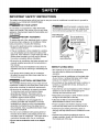 3
3
-
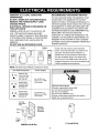 4
4
-
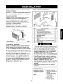 5
5
-
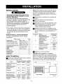 6
6
-
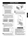 7
7
-
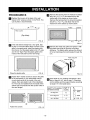 8
8
-
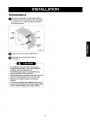 9
9
-
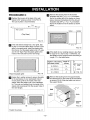 10
10
-
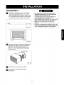 11
11
-
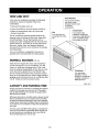 12
12
-
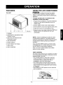 13
13
-
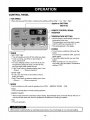 14
14
-
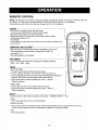 15
15
-
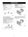 16
16
-
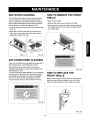 17
17
-
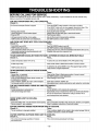 18
18
-
 19
19
-
 20
20
-
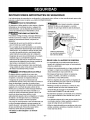 21
21
-
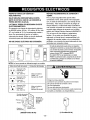 22
22
-
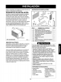 23
23
-
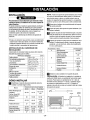 24
24
-
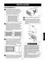 25
25
-
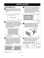 26
26
-
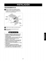 27
27
-
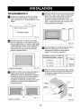 28
28
-
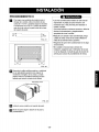 29
29
-
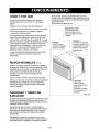 30
30
-
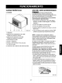 31
31
-
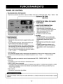 32
32
-
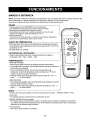 33
33
-
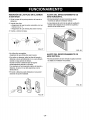 34
34
-
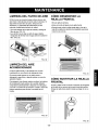 35
35
-
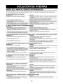 36
36
-
 37
37
-
 38
38
-
 39
39
-
 40
40


Kenmore 580.75098500 El manual del propietario
- Tipo
- El manual del propietario
- Este manual también es adecuado para
en otros idiomas
- English: Kenmore 580.75098500 Owner's manual
Artículos relacionados
-
Kenmore 75135 501 Manual de usuario
-
-
Kenmore 580.75119500 El manual del propietario
-
-
-
-
Kenmore 580.73093300 El manual del propietario
-