Kichler Lighting 43824WZC Manual de usuario
- Tipo
- Manual de usuario

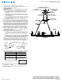
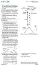
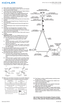
1) Slip loop at top of arm over hook on top trim.
2) Pass fixture wire at end of length of chain through hole in
small loop attached to canopy.
3) TURN OFF POWER.
IMPORTANT: Before you start, NEVER attempt any work
without shutting off the electricity until the work is done.
a) Go to the main fuse, or circuit breaker, box in your
home. Place the main power switch in the “OFF”
position.
b) Unscrew the fuse(s), or switch “OFF” the circuit breaker
switch(s), that control the power to the fixture or room that
you are working on.
c) Place the wall switch in the “OFF” position. If the fixture
to be replaced has a switch or pull chain, place those in
the “OFF” position.
4) Thread hexnut onto threaded pipe so that 5 threads are
exposed above hexnut. Thread that end of threaded pipe
into mounting strap and tighten hexnut against mounting strap.
5) Run another hexnut down threaded pipe almost touching
first hexnut. Now screw threaded pipe into mounting strap.
Mounting strap must be positioned with extruded thread
faced into outlet box. Threaded pipe must protrude out the
back of mounting strap. Screw third hexnut onto end of
threaded pipe protruding from back of mounting strap.
6) Attach mounting strap to outlet box. (Screws not provided)
7) Connect safety cable assembled to canopy to mounting
strap. (This will allow for fixture to be supported while wire
connections are made.)
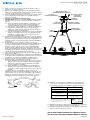
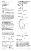
8) Grounding instructions: (See Illus. A or B).
A) On fixtures where mounting strap is provided with a
hole and two raised dimples. Wrap ground wire from
outlet box around green ground screw, and thread into
hole.
B) On fixtures where a cupped washer is provided. Attach
ground wire from outlet box under cupped washer and
green ground screw, and thread into mounting strap.
If fixture is provided with ground wire. Connect fixture
ground wire to outlet box ground wire with wire connector.
(Not provided.) After following the above steps. Never
connect ground wire to black or white power supply wires.
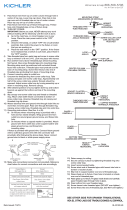
9) Make wire connections (connectors not provided.) Reference
chart below for correct connections and wire accordingly.
10) Push fixture to ceiling, carefully passing threaded pipe
through hole in canopy.
11) Thread finial onto threaded pipe. Tighten finial to secure
fixture to ceiling.
GREEN GROUND
SCREW
CUPPED
WASHER
A
B
OUTLET BOX
GROUND
FIXTURE
GROUND
DIMPLES
WIRE CONNECTOR
(NOT PROVIDED)
OUTLET BOX
GROUND
GREEN GROUND
SCREW
FIXTURE
GROUND
Connect Black or
Red Supply Wire to:
Connect
White Supply Wire to:
Black White
*Parallel cord (round & smooth) *Parallel cord (square & ridged)
Clear, Brown, Gold or Black
without tracer
Clear, Brown, Gold or Black
with tracer
Insulated wire (other than green)
with copper conductor
Insulated wire (other than green)
with silver conductor
*Note: When parallel wires (SPT I & SPT II)
are used. The neutral wire is square shaped
or ridged and the other wire will be round in
shape or smooth (see illus.)
Neutral Wire
Date Issued: 9/18/15 IS-43824-US
SEE OTHER SIDE FOR SPANISH TRANSLATIONS.
VEA EL OTRO LADO DE TRADUCCIONES AL ESPAÑOL.
We’re here to help 866-558-5706
Hrs: M-F 9am to 5pm EST
FINIAL
CAPUCHÓN
MOUNTING STRAP
ABRAZADERA DE MONTAJE
CANOPY
ESCUDETE
SMALL LOOP
ANILLO PEQUEÑA
HEXNUT
TUERCA HEXAGONAL
SAFETY CABLE
CABLE DE
SEGURIDAD
LARGE LOOP
ANILLO GRANDE
ARM
BRAS
RING
ANILLO
LOOP
ANILLO
HOOK
GANCHO

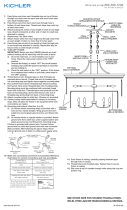
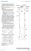
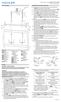
1) Deslice el lazo en el extremo superior del brazo sobre el
gancho en el adorno superior.
2) Entreteja los alambres del artefacto desde anillo grande a
través de los eslabones de cadena en cada largo de cadena
con una separación mayor a 3 pulgadas.
3) Pase los alambres del artefacto en el extremo de la longitud
de la cadenaa través del agujero en un anillo pequeño
sujeto al escudete.
4) APAGUE LA ALIMENTACIÓN ELÉCTRICA.
IMPORTANTE: Antes de comenzar, NUNCA trate de trabajar
sin antes desconectar la corriente hasta que el trabajo se
termine.
a) Vaya a la caja principal de fusibles, o interruptor o caja
de circuitos de su casa. Coloque el interruptor de la
corriente principal en posición de apagado “OFF”.
b) Desatornille el (los) fusible (s), o coloque el interruptor o
interruptores del breaker en posición de apagado
“OFF”, que controla (n) la corriente hacia el artefacto o
habitación donde está trabajando.
c) Coloque el interruptor de pared en posición de apagado
“OFF”. Si el artefacto que se va a reemplazar tiene un
interruptor o cadena que se jala, colóquelos en la
posición de apagado “OFF”.
5) Atornille la tuerca hexagonal en el tubo roscado de manera
que 5 roscas estén expuestas arriba de la tuerca hexagonal.
Rosque ese extremo del tubo roscado en la abrazadera de
montaje y apriete la tuerca hexagonal contra la abrazadera
de montaje.
6) Instale otra tuerca hexagonal en el tubo roscado casi
tocando la primera tuerca hexagonal. Ahora, atornille el tubo
roscado en la abrazadera de montaje. La abrazadera de
montaje se debe colocar con la rosca extruida mirando
hacia la caja de salida. El tubo roscado debe sobresalir
atrás de la abrazadera de montaje. Atornille la tercera tuerca
hexagonal en el extremo del tubo roscado que sobresale de
la parte posterior de la abrazadera de montaje.
7) Sujete la plancha para montar a la caja de conexión. (No se
proveen los tornillos.)
8) Acople el cable de seguridad en la ranura de la abrazadera
de montaje. (Esto permitirá que el artefacto que se va a usar
mientras las conexiones de alambre están hechos.)
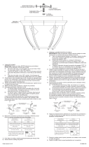
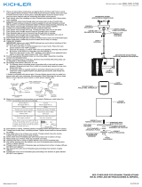
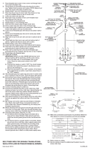
9) Instrucciones de conexión a tierra solamente para los
Estados Unidos. (Vea la ilustracion A o B).
A) En las lámparas que tienen el fleje, de montaje con un
agujero y dos hoyuelos realzados. Enrollar el alambre a
tierra de la caja tomacorriente alrededor del tornillo
verde y pasarlo por el aquiero.
B) En las lámparas con una arandela acopada. Fijar el
alambre a tierra de la caja tomacorriente del ajo de la
arandela acoada y tornillo verde, y paser por el fleje de
montaje.
Si la lámpara viene con alambre a tierra. Conecter el
alambre a tierra de la lámpara al alambre a tierra de la caja
tomacorriente con un conector de alambres. (No incluido)
Espués de seguir los pasos anteriores. Nunca conectar el
alambra a tierra a los alambres eléctros negro o blanco.
Date Issued: 9/18/15 IS-43824-US
10) Haga les conexiones de los alambres (no se proveen los
connectores.) La tabla de referencia de abajo indica las
conexiones correctas y los alambres correspondientes.
11) Empuje el artefacto contra la techo, pasando con cuidado el
tubo roscado a través del agujero en la cubierta.
12) Atornille la capuchón en el tubo roscado. Apriete el capuchón
para asegurar el artefacto al techo.
GREEN GROUND
SCREW
CUPPED
WASHER
A
B
OUTLET BOX
GROUND
FIXTURE
GROUND
DIMPLES
WIRE CONNECTOR
(NOT PROVIDED)
OUTLET BOX
GROUND
GREEN GROUND
SCREW
FIXTURE
GROUND
Connect Black or
Red Supply Wire to:
Connect
White Supply Wire to:
Black White
*Parallel cord (round & smooth) *Parallel cord (square & ridged)
Clear, Brown, Gold or Black
without tracer
Clear, Brown, Gold or Black
with tracer
Insulated wire (other than green)
with copper conductor
Insulated wire (other than green)
with silver conductor
*Note: When parallel wires (SPT I & SPT II)
are used. The neutral wire is square shaped
or ridged and the other wire will be round in
shape or smooth (see illus.)
Neutral Wire
SEE OTHER SIDE FOR ENGLISH TRANSLATIONS.
VEA EL OTRO LADO DE TRADUCCIONES AL INGLÉS.
We’re here to help 866-558-5706
Hrs: M-F 9am to 5pm EST
FINIAL
CAPUCHÓN
MOUNTING STRAP
ABRAZADERA DE MONTAJE
CANOPY
ESCUDETE
SMALL LOOP
ANILLO PEQUEÑA
HEXNUT
TUERCA HEXAGONAL
SAFETY CABLE
CABLE DE
SEGURIDAD
LARGE LOOP
ANILLO GRANDE
ARM
BRAS
RING
ANILLO
LOOP
ANILLO
HOOK
GANCHO
-
 1
1
-
 2
2


Kichler Lighting 43824WZC Manual de usuario
- Tipo
- Manual de usuario
en otros idiomas
Artículos relacionados
-
 Kichler Lighting 9886TZ Manual de usuario
-
 Kichler Lighting 43745OZ Manual de usuario
-
 Kichler Lighting 43491AUB Manual de usuario
-
 Kichler Lighting 43153AP Manual de usuario
-
 Kichler Lighting 43755AUB Manual de usuario
-
 Kichler Lighting 43433AUB Manual de usuario
-
 Kichler Lighting 43324DAG Manual de usuario
-
 Kichler Lighting 42474PN Manual de usuario
-
 Kichler Lighting 42497NI Manual de usuario
-
 Kichler Lighting 42568BK Manual de usuario


