
EN
User manual 2
DE
Benutzerinformation 7
IT
Istruzioni per l’uso 13
FR
Notice d'utilisation 18
ES
Manual de instrucciones 23
HR
Upute za uporabu 28
SL
Navodila za uporabo 33
Washer/Dryer Stand with Drawer
Wasch-/Trockner-Unterbau mit
Schublade
Piedistallo con cassetto per
lavabiancheria/asciugatrice
Socle avec tiroir de rangement pour
lave-linge/sèche-linge
Soporte con cajón para lavadora/
secadora
Postolje za perilicu/sušilicu
rublja s ladicom
Stojalo za pralni/sušilni stroj s
predalom

Contents
How to install the stand on your washing
machine _ _ _ _ _ _ _ _ _ _ _ _ _ _ _ _ _ _ _ _ _ 2
How to install the stand on your tumble dryer _ _ _ _ 4
Subject to change without notice
How to install the stand on your washing machine
Warning! Do not install the stand on a washer/dryer
column.
Caution! If the washing machine is already
connected to the mains, proceed as follows:
1. pull out the plug from the mains;
2. stop water supply by closing the tap;
3. disconnect the inlet pipe and the drain pipe and get
ready to collect any water left in the machine with a
shallow basin.
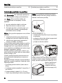
Important! With a brand new washing machine, do as
follows:
1. install the stand before connecting the machine to
water and electricity mains;
2. follow the instructions to remove any transport safety
equipment.
Before you start installing the stand on your washing ma-
chine make sure you have plenty of room. Avoid working
in restricted spaces as the installation and subsequent
adjustment operations may turn out quite awkward and
difficult to carry out.
Take the stand out of its package and use the cardboard
to rest washing machine and stand on, so you wont
scratch the equipment varnish and the floor.
In the stands drawer you will find an envelope with all the
necessary material for a correct assembly.
Have ready a Phillips screwdriver to fit rear brackets to
the stand
.
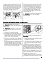
The pack includes:
• 2 front rubber feet (for tumble dryer only);
• 4 rear metal brackets (2 for washing machine and 2 for
tumble dryer);
• 6 self-tapping screws (4.2 x 13 mm);
• 1 key to adjust stand feet.
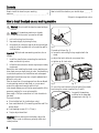
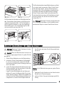
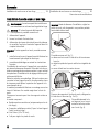
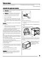
Important! Before starting the installation, adjust the
stand's feet in order to achieve a perfectly stable hori-
zontal position.
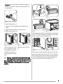
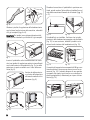
fig. 1
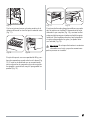
Proceed as follows (fig. 1):
• loosen the nuts using the key supplied with the
stand;
• adjust the feet to allow for an uneven floor;
• tighten up all check nuts.
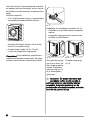
fig. 2 fig. 3
Fit one of the rear brackets to the left side of the stands
back using the screws supplied (fig. 2 and 3).
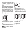
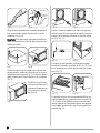
fig. 4
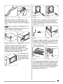
Lay gently the washing
machine on the detergent
compartment side (fig. 4).
2

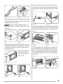
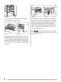
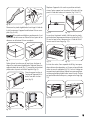
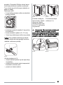
fig. 5 fig. 6
Loosen the washing machines adjusting feet using the
key supplied with your washing machine, then undo 5
complete turns (fig. 5 and 6).
Important! If the feet are already partly undone, you
must first screw them on again and then undo 5 com-
plete turns.
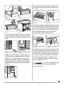
fig. 7 fig. 8
Slide the stand under the washing machine so that its
front adjusting feet match the stands front brackets (fig.
7) and the rear bracket is positioned against the ma-
chines back (fig. 8).
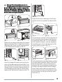
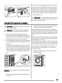
fig. 9
Screw the rear bracket on-
to the machines back us-
ing one of the supplied
screws (fig. 9).
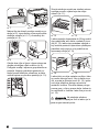
fig. 10 fig. 11
Return machine and stand to a vertical position, and
screw the other bracket onto the stand and the machines
back using the remaining supplied screws (fig. 10 and
11).
fig. 12 fig. 13
The stand is now installed; check whether your washing
machines back feet rest on it (fig. 12). Otherwise undo
them using the key supplied with your washing machine
(fig. 13).
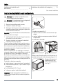
fig. 14 fig. 15
The stands drawer, with a capacity of up to 20 kg, con-
tains two dividers; they may be taken out if you wish
(fig. 14). The drawer was designed with a special com-
partment inside where you can place a folding plastic
box, supplied, quite useful to store your washing laun-
dry (fig. 15).
fig. 16 fig. 17
3
x5

The drawer slides on two metal runners and can easily
be pulled out to the full. Should you wish to remove the
drawer, you must pull it out completely (fig. 16) and act
on the two black plastic levers halfway through the
metal runners. Pull the right lever up and the left lever
down: the drawer will be uncoupled from the runners
and easily removed (fig. 17).
Warning! Do not place any solvent or flammable
substance into the drawer, as the fumes could be a
possible cause of fire.
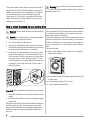
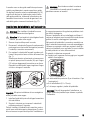
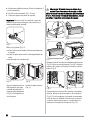
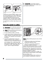
How to install the stand on your tumble dryer
Warning! Do not install the stand on a washer/dryer
column.
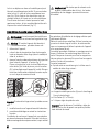
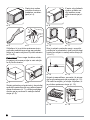
Caution! If the tumble dryer is already connected
to the mains, proceed as follows:
1. Pull out the plug from the mains;
2. remove the condensation tank found in the upper or
alternatively lower part of the tumble dryer (according
to machine type) and empty it, if necessary;
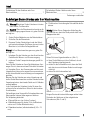
3. Drain off any condensation water through the hose
found on the lower part of the machines back (fig. 1).
Place a mop on the floor and remove first the clamp
(A) using a pair of pliers, then the cap (B). Tilt the
machine slightly on one side. When all the water has
drained off, put the cap back onto the hose and re-
fasten the clamp.
fig. 1
Important! With a brand new tumble dryer, do as follows:
1. install the stand before connecting the machine to the
mains;
2. follow the instructions to remove any transport safety
equipment.
Before you start fitting the stand to the machine make sure
you have plenty of room. Avoid working in restricted
spaces as the installation and subsequent adjustment
operations may turn out quite awkward and difficult to
carry out.
Take the stand out of its package and use the cardboard
to rest machine and stand on, so you wont scratch the
equipment varnish and the floor.
In the stands drawer you will find an envelope with all the
necessary material for a correct assembly. Have ready a
Phillips screwdriver to fit rear brackets to the stand and
an Torx screwdriver to fit rear brackets to the machines
back.
The pack includes:
• 2 grey short rubber feet to be used for the following
tumble dryer models:
4
A
B
• 4 rear metal brackets (2 for washing machine and 2 for
tumble dryer) ;
• 6 self-tapping screws (4.2 x 13 mm);
• 1 key to adjust the stands feet.

Important! Before starting the installation, adjust the
stand's feet in order to achieve a perfectly stable hori-
zontal position.
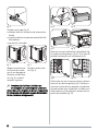
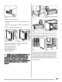
fig. 2
Proceed as follows (fig. 2):
• loosen the nuts using the key supplied with the
stand;
• adjust the feet to allow for an uneven floor;
• tighten up all check nuts.
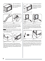
fig. 3 fig. 4
Lay the machine on its left
side, making sure you do
not damage it. Remove the
front feet (fig. 3) and re-
place them with the rubber
ones.
Tighten the back feet (fig.
4).
Warning! If you install the stand under an energy
saver model Class A, you must not use the tumble
dryer immediately. Please wait 8 hours at least. For more
detailed information, read the appliance user manual
carefully.
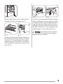
fig. 5
fig. 6
fig. 7 fig. 8
After having removed the front brackets from the stand
(fig. 5), fit the rear brackets (fig. 6 and 7) to the stands
back, using the screws supplied (fig. 8).
fig. 9 fig. 10
Undo the two screws found left and right on the lower
part of the tumble dryer back (fig. 9). Lift the machine
and correctly place it over the stand, trying to position
first the stand against the rear brackets and then the
suction caps over the stand surface (fig. 10).
5
S
X
DX

fig. 11
Fit the rear brackets to the machines back using the
previously removed screws (fig. 11).
fig. 12 fig. 13
The stands drawer, with a capacity of up to 20 kg, con-
tains two dividers; they may be taken out if you wish
(fig. 12). The drawer was designed with a special com-
partment inside where you can place a folding plastic
box, supplied, quite useful to store your washing laun-
dry (fig. 13).
fig. 14 fig. 15
The drawer slides on two metal runners and can easily
be pulled out to the full. Should you wish to remove the
drawer, you must pull it out completely (fig. 14) and act
on the two black plastic levers halfway through the
metal runners. Pull the right lever up and the left lever
down: the drawer will be uncoupled from the runners
and easily removed (fig. 15).
Warning! Do not place any solvent or flammable
substance into the drawer, as the fumes could be a
possible cause of fire.
6

Inhalt
So befestigen Sie den Unterbau unter Ihrer
Waschmaschine _ _ _ _ _ _ _ _ _ _ _ _ _ _ _ _ _ 7
So befestigen Sie den Unterbau unter Ihrem
Wäschetrockner _ _ _ _ _ _ _ _ _ _ _ _ _ _ _ _ _ _ 9
Änderungen vorbehalten
So befestigen Sie den Unterbau unter Ihrer Waschmaschine
Warnung! Befestigen Sie den Unterbau nicht unter
einer Wasch-/Trocknersäule.
Vorsicht! Wenn die Waschmaschine bereits an die
Netzversorgung angeschlossen ist, gehen Sie bitte
wie folgt vor:
1. Ziehen Sie den Netzstecker aus der Netzsteckdose.
2. Schließen Sie den Wasserhahn.
3. Klemmen Sie den Zulaufschlauch und den Ablauf-
schlauch ab und fangen Sie Wasser, das noch in der
Maschine ist, mit einem Auffangbehälter auf.
Wichtig! Ist Ihre Waschmaschine ganz neu, gehen Sie
wie folgt vor:
1. befestigen Sie den Unterbau vor dem Anschluss des
Gerätes an die Wasser- und Stromversorgung;
2. entfernen Sie die Transportsicherungen gemäß An-
leitung.
Bevor Sie den Unterbau an Ihrem Gerät befestigen, über-
zeugen Sie sich, dass ausreichend Platz dafür vorhanden
ist. Vermeiden Sie es, den Zusammenbau und die nach-
folgende Ausrichtung auf zu engem Raum vorzunehmen,
da sich diese Arbeiten sonst schwierig und unangenehm
gestalten.
Nehmen Sie den Unterbau aus seiner Verpackung und
stellen Sie die Waschmaschine und den Unterbau auf den
Verpackungskarton, damit weder Geräte noch Fußboden
verkratzt werden.
In der Schublade des Unterbaus finden Sie einen Um-
schlag mit allen erforderlichen Teilen für den korrekten
Zusammenbau.
Sie benötigen einen Kreuzschlitz-Schraubendreher zum
Anbringen der hinteren Halterungen am Unterbau
.
Die Verpackung beinhaltet:
• 2 Gummifüße vorn (nur für den Trockner);
• 4 Metallhalterungen für hinten (2 für die Waschma-
schine und 2 für den Wäschetrockner);
• 6 Gewindeschrauben (selbstschneidend) (4,2 x 13
mm);
• 1 Schlüssel zur Ausrichtung der Schraubfüße des Un-
terbaus.
Wichtig! Richten Sie vor Beginn der Aufstellung die
Schraubfüße aus, damit das Gerät perfekt stabil in der
Waagerechten steht.
Abb. 1
Gehen Sie hierzu folgendermaßen vor (Abb. 1):
• lösen Sie die Muttern mit dem Schlüssel, der mit
dem Unterbau mitgeliefert wurde;
• stellen Sie die Schraubfüße so ein, dass das Gerät
auch bei einem nicht ebenen Boden korrekt ausge-
richtet ist;
• ziehen Sie alle Kontermuttern fest.
Abb. 2 Abb. 3
Bringen Sie eine der hinteren Halterungen auf der linken
Rückseite des Unterbaus mit den mitgelieferten
Schrauben an (Abb. 2 und 3).
7

Abb. 4
Legen Sie die Waschma-
schine vorsichtig auf die
Seite mit dem Waschmit-
telfach (Abb. 4).
Abb. 5 Abb. 6
Lösen Sie die Schraubfüße der Waschmaschine mit
dem Schlüssel, der mit Ihrer Waschmaschine mitge-
liefert wurde, und drehen Sie dann die Schraubfüße 5
volle Umdrehungen auf (Abb. 5 und 6).
Wichtig! Wurden die Schraubfüße bereits zuvor aufge-
dreht, schrauben Sie diese erst wieder fest und danach
5 volle Umdrehungen auf.
Abb. 7 Abb. 8
Schieben Sie den Unterbau so unter die Waschma-
schine, dass die vorderen Schraubfüße auf die vorderen
Halterungen des Unterbaus (Abb. 7) ausgerichtet sind
und die hintere Halterung an der Maschinenrückseite
sitzt (Abb. 8).
Abb. 9
Schrauben Sie die hintere
Halterung auf der Maschi-
nenrückseite mit einer der
mitgelieferten Schrauben
fest (Abb. 9).
Abb. 10 Abb. 11
Bringen Sie die Maschine mit dem Unterbau wieder in
eine vertikale Position, und schrauben Sie mit den
restlichen mitgelieferten Schrauben die andere Halte-
rung an den Unterbau und an die Maschinenrückseite
(Abb. 10 und 11).
Abb. 12 Abb. 13
Der Unterbau ist jetzt an der Waschmaschine befestigt;
prüfen Sie, ob alle Schraubfüße Ihrer Waschmaschine
fest auf dem Unterbau stehen (Abb. 12). Lösen Sie im
anderen Fall die Schraubfüße der Waschmaschine mit
dem Schlüssel, der mit Ihrer Waschmaschine mitge-
liefert wurde (Abb. 13).
8
x5

Abb. 14 Abb. 15
Die Schublade des Unterbaus mit
20 kg Nutzinhalt hat
zwei Trenneinsätze; diese können je nach Wunsch he-
rausgenommen werden (Abb. 14). Die Schublade be-
sitzt ein spezielles Innenfach, in das die mitgelieferte
Kunststoffbox passt, die zur Aufbewahrung Ihrer Wä-
sche sehr nützlich sein kann (Abb. 15).
Abb. 16 Abb. 17
Die Schublade gleitet auf zwei Metallschienen und lässt
sich einfach ganz herausziehen. Wenn Sie die Schub-
lade entfernen möchten, müssen Sie diese ganz he-
rausziehen (Abb. 16) und die beiden schwarzen Kunst-
stoffhebel in der Mitte der Metallschienen betätigen.
Ziehen Sie den rechten Hebel hoch und drücken Sie
den linken Hebel nach unten: die Schublade kommt jetzt
aus den Schienen frei und lässt sich einfach heraus-
ziehen (Abb. 17).
Warnung! Bitte legen Sie keine Lösungsmittel oder
brennbaren Substanzen in die Schublade, da die
entstehenden Dämpfe zu einem Brand führen können.
So befestigen Sie den Unterbau unter Ihrem Wäschetrockner
Warnung! Befestigen Sie den Unterbau nicht unter
einer Wasch-/Trocknersäule.
Vorsicht! Wenn der Wäschetrockner bereits an die
Netzversorgung angeschlossen ist, gehen Sie bitte
wie folgt vor:
1. Ziehen Sie den Netzstecker aus der Netzsteckdose.
2. entnehmen Sie den Kondenswasser-Auffangbehäl-
ter, der sich im oberen oder unteren Teil des Wä-
schetrockners befindet (je nach Gerätetyp) und leeren
Sie ihn bei Bedarf;
3. Lassen Sie das gesamte Kondenswasser durch den
Schlauch ablaufen, den Sie am unteren Teil der Ma-
schinenrückseite finden (Abb. 1).
Legen Sie einen Wischlappen auf den Boden und
entfernen Sie zuerst die Klemmschelle (A) mit einer
Zange, dann die Kappe (B). Neigen Sie die Maschine
leicht auf eine Seite. Wenn das gesamte Wasser he-
rausgelaufen ist, stecken Sie die Kappe wieder auf
den Schlauch und ziehen Sie die Klemmschelle wie-
der fest an.
Abb. 1
Wichtig! Ist Ihr Wäschetrockner ganz neu, gehen Sie wie
folgt vor:
1. befestigen Sie den Unterbau vor dem Anschluss des
Gerätes an die Stromversorgung;
2. entfernen Sie die Transportsicherungen gemäß An-
leitung.
9
A
B

Bevor Sie den Unterbau an Ihrem Gerät befestigen, über-
zeugen Sie sich, dass ausreichend Platz dafür vorhanden
ist. Vermeiden Sie es, den Zusammenbau und die nach-
folgende Ausrichtung auf zu engem Raum vorzunehmen,
da sich diese Arbeiten sonst schwierig und unangenehm
gestalten.
Nehmen Sie den Unterbau aus seiner Verpackung und
stellen Sie das Gerät und den Unterbau auf den Verpa-
ckungskarton, damit weder Gerät noch Fußboden ver-
kratzt werden.
In der Schublade des Unterbaus finden Sie einen Um-
schlag mit allen erforderlichen Teilen für den korrekten
Zusammenbau. Sie benötigen einen Kreuzschlitz-
Schraubendreher zum Anbringen der hinteren Halterun-
gen am Unterbau und zur Montage der hinteren Halte-
rungen an der Maschine.
Die Verpackung beinhaltet:
• 2 graue kurze Gummifüße für folgende Wäschetrock-
nermodelle:
• 4 Metallhalterungen für hinten (2 für die Waschma-
schine und 2 für den Wäschetrockner) ;
• 6 Gewindeschrauben (selbstschneidend) (4,2 x 13
mm);
• 1 Schlüssel zur Ausrichtung der Schraubfüße des Un-
terbaus.
Wichtig! Richten Sie vor Beginn der Aufstellung die
Schraubfüße aus, damit das Gerät perfekt stabil in der
Waagerechten steht.
Abb. 2
Gehen Sie hierzu folgendermaßen vor (Abb. 2):
• lösen Sie die Muttern mit dem Schlüssel, der mit
dem Unterbau mitgeliefert wurde;
• stellen Sie die Schraubfüße so ein, dass das Gerät
auch bei einem nicht ebenen Boden korrekt ausge-
richtet ist;
• ziehen Sie alle Kontermuttern fest.
Abb. 3
10
Abb. 4
Legen Sie das Gerät auf
seine linke Seite und ach-
ten Sie dabei darauf , dass
es nicht beschädigt wird.
Schrauben Sie die vorde-
ren Füße ab (Abb. 3) und
ersetzen Sie diese durch
Gummifüße.
Ziehen Sie die hinteren
Füße fest (Abb. 4).

Warnung! Wenn Sie den Unterbau unter ein
Energiesparmodell der Klasse A installieren, dürfen
Sie ihren Wäschetrockner nicht sofort benutzen. Bitte
warten Sie damit mindestens 8 Stunden. Für detaillierte
Informationen zur Benutzung des Gerätes lesen Sie bitte
die Gebrauchsanweisung sorgfältig durch.
Abb. 5
Abb. 6
Abb. 7 Abb. 8
Nachdem Sie die vorderen Halterungen vom Unterbau
abgenommen haben (Abb. 5), bringen Sie die hinteren
Halterungen (Abb. 6 und 7) an der Unterbaurückseite
mit den mitgelieferten Schrauben an (Abb. 8).
Abb. 9 Abb. 10
Lösen Sie die beiden Schrauben rechts und links am
unteren Teil der Wäschetrocknerrückseite (Abb. 9). He-
ben Sie das Gerät an und stellen Sie es korrekt auf den
Unterbau. Setzen Sie zuerst den Unterbau an den hint-
eren Halterungen an und bringen Sie dann die Saug-
kappen auf der Oberfläche des Unterbaus an (Abb. 10).
Abb. 11
Bringen Sie die hinteren Halterungen an der Geräte-
rückseite mit den zuvor gelösten Schrauben an (Abb.
11).
Abb. 12 Abb. 13
Die Schublade des Unterbaus mit 20 kg Nutzinhalt hat
zwei Trenneinsätze; diese können je nach Wunsch he-
rausgenommen werden (Abb. 12). Die Schublade be-
sitzt ein spezielles Innenfach, in das die mitgelieferte
Kunststoffbox passt, die zur Aufbewahrung Ihrer Wä-
sche sehr nützlich sein kann (Abb. 13).
Abb. 14 Abb. 15
Die Schublade gleitet auf zwei Metallschienen und lässt
sich einfach ganz herausziehen. Wenn Sie die Schub-
lade entfernen möchten, müssen Sie diese ganz he-
rausziehen (Abb. 14) und die beiden schwarzen Kunst-
stoffhebel in der Mitte der Metallschienen betätigen.
Ziehen Sie den rechten Hebel hoch und drücken Sie
den linken Hebel nach unten: die Schublade kommt jetzt
aus den Schienen frei und lässt sich einfach heraus-
ziehen (Abb. 15).
11
S
X
DX

Warnung! Bitte legen Sie keine Lösungsmittel oder
brennbaren Substanzen in die Schublade, da die
entstehenden Dämpfe zu einem Brand führen können.
12

Indice
Installazione del piedistallo sulla
lavabiancheria _ _ _ _ _ _ _ _ _ _ _ _ _ _ _ _ _ _ 13
Installazione del piedistallo sull'asciugatrice _ _ _ 15
Con riserva di modifiche
Installazione del piedistallo sulla lavabiancheria
Avvertenza Non installare il piedistallo su una
colonna lavabiancheria/asciugatrice.
Attenzione Se la lavabiancheria è già collegata alla
rete elettrica, procedere come segue:
1. Staccare la spina dalla presa di corrente;
2. Chiudere il rubinetto dell'acqua;
3. Scollegare i tubi di carico e scarico dell'acqua e po-
sizionare una bacinella per raccogliere l'acqua rima-
sta all'interno della macchina.
Importante Alla prima installazione di una lavabiancheria
nuova, procedere come segue:
1. Installare il piedistallo prima di collegare la macchina
alla rete idrica e alla rete elettrica;
2. Seguire le istruzioni per rimuovere il materiale di
protezione usato per il trasporto.
Prima di installare il piedistallo sulla macchina, assicu-
rarsi di avere sufficiente spazio a disposizione. È preferi-
bile non lavorare in spazi ristretti poiché l'installazione e
le successive operazioni di regolazione potrebbero risul-
tare difficili da eseguire.
Estrarre il piedistallo dal suo imballaggio e utilizzare il
cartone per adagiarvi sopra la lavabiancheria in modo da
non graffiare la vernice o danneggiare il pavimento.
Nel cassetto del piedistallo è presente un sacchetto con
tutto il materiale necessario per un corretto assemblaggio.
Utilizzare un cacciavite per montare le staffe posteriori sul
piedistallo
.
Il materiale in dotazione comprende:
• 2 piedini anteriori in gomma (solo per l'asciugatrice);
• 4 staffe metalliche posteriori (2 per la lavatrice e 2 per
l'asciugatrice);
• 6 viti autofilettanti (4,2 x 13 mm);
• 1 chiave per regolare i piedini del piedistallo.
Importante Prima di intraprendere l'installazione, re-
golare i piedini del piedistallo per ottenere un perfetto
livellamento.
fig. 1
Procedere come segue (fig. 1):
• allentare i dadi con la chiave fornita insieme al pie-
distallo;
• regolare i piedini per compensare eventuali dislivelli
del pavimento;
• serrare tutti i controdadi.
fig. 2 fig. 3
Montare una delle staffe posteriori sul lato sinistro del
piedistallo utilizzando le viti in dotazione (figg. 2 e 3).
fig. 4
Adagiare delicatamente la
lavabiancheria sul lato
dello scomparto del deter-
sivo (fig. 4).
13

fig. 5 fig. 6
Allentare i piedini di regolazione della lavabiancheria
con la chiave fornita insieme alla macchina, svitandoli
di 5 giri completi (figg. 5 e 6).
Importante Se i piedini sono già parzialmente svitati,
occorre prima riavvitarli e poi svitarli di 5 giri completi.
fig. 7 fig. 8
Inserire il piedistallo sotto la lavabiancheria in modo
che i suoi piedini di regolazione anteriori siano allineati
con le staffe anteriori del piedistallo (fig. 7) e la staffa
posteriore sia posta a contatto con il retro della mac-
china (fig. 8).
fig. 9
Avvitare la staffa posterio-
re sul retro della macchina
utilizzando una delle viti in
dotazione (fig. 9).
fig. 10 fig. 11
Rimettere la macchina e il piedistallo in posizione ver-
ticale, quindi avvitare l'altra staffa sul piedistallo e sul
retro della macchina utilizzando le viti restanti (figg. 10
e 11).
fig. 12 fig. 13
Il piedistallo è ora installato. Verificare che i piedini
posteriori della lavabiancheria poggino sul piedistallo
(fig. 12). In caso contrario, allentare i piedini con la
chiave fornita insieme alla lavabiancheria (fig. 13).
fig. 14 fig. 15
Il cassetto del supporto ha una capacità di 20 kg e con-
tiene due divisori che possono essere rimossi se ne-
cessario (fig. 14). Il cassetto dispone di uno speciale
scomparto nel quale si può inserire un contenitore in
plastica pieghevole (in dotazione) per riporre la bian-
cheria (fig. 15).
fig. 16 fig. 17
14
x5

Il cassetto scorre su due guide metalliche e può essere
estratto completamente in maniera semplice e rapida.
Per togliere il cassetto, estrarlo completamente (fig. 16)
e agire sulle due leve in plastica nera poste al centro
delle guide metalliche, sollevando la leva destra e ab-
bassando la leva sinistra, in modo da sganciare il cas-
setto dalle guide e rimuoverlo facilmente (fig. 17).
Avvertenza Non introdurre solventi o sostanze
infiammabili nel cassetto poiché le esalazioni
potrebbero causare un incendio.
Installazione del piedistallo sull'asciugatrice
Avvertenza Non installare il piedistallo su una
colonna lavabiancheria/asciugatrice.
Attenzione Se l'asciugatrice è già collegata alla rete
elettrica, procedere come segue:
1. Staccare la spina dalla presa di corrente;
2. Rimuovere il serbatoio dell'acqua di condensa nella
parte superiore o inferiore dell'asciugatrice (secondo
il modello) e svuotarlo se necessario;
3. Per svuotare il serbatoio dell'acqua di condensa, uti-
lizzare il tubo posto in basso sul retro della macchina
(fig. 1).
Stendere uno straccio sul pavimento e rimuovere con
un paio di pinze prima il manicotto (A) e poi il tappo
(B). Inclinare leggermente la macchina su un fianco.
Quando è fuoriuscita tutta l'acqua, riapplicare il tappo
sul tubo e stringere il manicotto.
fig. 1
Importante Alla prima installazione di una asciugatrice
nuova, procedere come segue:
1. Installare il piedistallo prima di collegare la macchina
alla rete elettrica;
2. Seguire le istruzioni per rimuovere il materiale di
protezione usato per il trasporto.
Prima di installare il piedistallo sulla macchina, assicu-
rarsi di avere sufficiente spazio a disposizione. È preferi-
bile non lavorare in spazi ristretti poiché l'installazione e
le successive operazioni di regolazione potrebbero risul-
tare difficili da eseguire.
Estrarre il piedistallo dal suo imballaggio e utilizzare il
cartone per adagiarvi sopra la macchina in modo da non
graffiare la vernice o danneggiare il pavimento.
Nel cassetto del piedistallo è presente un sacchetto con
tutto il materiale necessario per un corretto assemblaggio.
Utilizzare un cacciavite a stella per montare le staffe po-
steriori sul piedistallo e un cacciavite Torx per installare
le staffe posteriori sul retro della macchina.
Il materiale in dotazione comprende:
• 2 piedini corti in gomma di colore grigio per i seguenti
modelli di asciugatrice:
15
A
B
• 4 staffe metalliche posteriori (2 per la lavatrice e 2 per
l'asciugatrice) ;
• 6 viti autofilettanti (4,2 x 13 mm);
• 1 chiave per regolare i piedini del piedistallo.
Importante Prima di intraprendere l'installazione, re-
golare i piedini del piedistallo per ottenere un perfetto
livellamento.

fig. 2
Procedere come segue (fig. 2):
• allentare i dadi con la chiave fornita insieme al pie-
distallo;
• regolare i piedini per compensare eventuali dislivelli
del pavimento;
• serrare tutti i controdadi.
fig. 3 fig. 4
Adagiare la macchina sul
suo lato sinistro avendo
cura di non danneggiarla.
Rimuovere i piedini ante-
riori (fig. 3) e sostituirli
con quelli in gomma.
Stringere i piedini poste-
riori (fig. 4).
Avvertenza Se si utilizza il piedistallo con
un'asciugatrice in classe energetica A, attendere
almeno 8 ore prima di mettere in funzione l'apparecchio.
Per informazioni più dettagliate, leggere attentamente il
libretto d'istruzioni dell'apparecchio.
fig. 5
fig. 6
fig. 7 fig. 8
Dopo aver rimosso le staffe anteriori dal piedistallo (fig.
5), montare le staffe posteriori (fig. 6 e 7) sul retro del
piedistallo utilizzando le viti in dotazione (fig. 8).
fig. 9 fig. 10
Svitare le due viti che si trovano a sinistra e a destra in
basso sul retro dell'asciugatrice (fig. 9). Sollevare la
macchina e posizionarla correttamente sul piedistallo,
cercando prima di porre il piedistallo a contatto con le
staffe posteriori e poi di applicare le ventose sulla su-
perficie del piedistallo (fig. 10).
16
S
X
DX

fig. 11
Montare le staffe posteriori sul retro della macchina
utilizzando le viti tolte in precedenza (fig. 11).
fig. 12 fig. 13
Il cassetto del supporto ha una capacità di 20 kg e con-
tiene due divisori che all'occorrenza possono essere
rimossi (fig. 12). Il cassetto dispone di uno speciale
scomparto nel quale si può inserire un contenitore in
plastica pieghevole (in dotazione) per riporre la bian-
cheria (fig. 13).
fig. 14 fig. 15
Il cassetto scorre su due guide metalliche e può essere
estratto completamente in maniera semplice e rapida.
Per togliere il cassetto, estrarlo completamente (fig. 14)
e agire sulle due leve in plastica nera poste al centro
delle guide metalliche, sollevando la leva destra e ab-
bassando la leva sinistra, in modo da sganciare il cas-
setto dalle guide e rimuoverlo facilmente (fig. 15).
Avvertenza Non introdurre solventi o sostanze
infiammabili nel cassetto poiché le esalazioni
potrebbero causare un incendio.
17

Sommaire
Installation du socle sous un lave-linge _ _ _ _ _ _ 18 Installation du socle sous un sèche-linge _ _ _ _ _ 20
Sous réserve de modifications
Installation du socle sous un lave-linge
Avertissement Le socle ne peut être installé sous
une installation en colonne lave linge/sèche-linge.
Attention Si le lave-linge est déjà branché
électriquement, procédez comme suit :
1. débranchez l'appareil ;
2. fermez le robinet d'arrivée d'eau ;
3. débranchez les tuyaux d'arrivée d'eau et de vidange,
et recueillez l'eau qui s'écoule de l'appareil dans un
récipient à bord bas.
Important Si votre appareil est neuf, procédez comme
suit :
1. installez le socle sous l'appareil avant d'effectuer les
branchements hydraulique et électrique ;
2. procédez au débridage en suivant les instructions
fournies.
L'installation du socle sous l'appareil est une opération
qui nécessite beaucoup d'espace. Évitez dès lors de pro-
céder au montage dans un espace restreint, ce qui rendrait
les opérations d'installation et de réglage ultérieur parti-
culièrement difficiles.
Retirez le socle de son emballage. Utilisez le carton pour
y coucher le lave-linge et le socle ; de cette manière, vous
ne risquerez pas d'abîmer la peinture de l'appareil ni le
recouvrement de sol.
Le matériel permettant d'effectuer un montage correct se
trouve à l'intérieur d'un sachet rangé dans le tiroir du
socle.
Prévoyez un tournevis pour fixer les supports arrière au
socle
.
Le sachet comprend :
•
2 pieds avant en caoutchouc (uniquement pour le sè-
che-linge) ;
• 4 supports métalliques arrière (2 pour le lave-linge et
2 pour le sèche-linge) ;
• 6 vis Parker (4,2 x 13 mm) ;
• 1 clé pour régler les pieds du socle.
Important Avant de démarrer l'installation, réglez les
pieds du socle, afin de garantir une position parfaite-
ment stable et de niveau.
fig. 1
Procédez comme suit (fig. 1) :
• desserrez les écrous à l'aide de la clé fournie avec
le socle ;
• réglez les pieds de façon à rectifier les inégalités du
sol ;
• serrez à fond tous les contre-écrous.
fig. 2 fig. 3
Fixez un des supports à l'arrière du socle, côté gauche,
à l'aide des vis fournies (fig. 2 et 3).
fig. 4
Posez délicatement le la-
ve-linge sur le sol, en ori-
entant la boîte à produits
vers le sol (fig. 4).
18

fig. 5 fig. 6
Desserrez les pieds réglables du lave-linge à l'aide de
la clé fournie avec l'appareil en effectuant 5 tours com-
plets (fig. 5 et 6).
Important Si les pieds sont déjà un peu desserrés, il est
nécessaire de les resserrer d'abord à fond, puis de les
desserrer en effectuant 5 tours complets.
fig. 7 fig. 8
Faites glisser le socle sous le lave-linge, de façon à
aligner les pieds avant réglables de l'appareil avec les
supports avant du socle (fig. 7), le support arrière étant
placé contre la paroi arrière de l'appareil (fig. 8).
fig. 9
Fixez le support arrière à
l'arrière de l'appareil à l'ai-
de de l'une des vis four-
nies (fig. 9).
fig. 10 fig. 11
Replacez l'appareil et le socle en position verticale,
vissez l'autre support sur le socle et à l'arrière de l'ap-
pareil à l'aide des autres vis fournies (fig. 10 et 11).
fig. 12 fig. 13
Le socle est à présent installé. Vérifiez que les pieds
arrière du lave-linge reposent bien sur le socle (fig. 12).
Si ce n'est pas le cas, desserrez-les à l'aide de la clé
fournie avec le lave-linge (fig. 13).
fig. 14 fig. 15
Le tiroir du socle, d'une capacité de 20 kg, incorpore
deux cloisons de séparation, qu'il vous est possible de
retirer si vous le souhaitez (fig. 14). Le tiroir intègre un
compartiment spécial dans lequel vous pouvez placer
un bac en plastique pliable fourni avec le socle. Ce bac
est particulièrement utile pour y ranger votre linge (fig.
15).
fig. 16 fig. 17
19
x5

Le tiroir se déplace sur deux rails métalliques et peut
être sorti complètement avec facilité. Si vous souhaitez
retirer le tiroir, il suffit de le tirer complètement vers
vous (fig. 16) et d'agir sur les deux leviers noirs en
plastique situés à mi-chemin sur les rails métalliques.
Tirez le levier droit vers le haut et poussez le levier
gauche vers le bas : le tiroir sera désolidarisé des rails
et pourra être extrait facilement (fig. 17).
Avertissement Ne stockez pas de solvants ou de
produits inflammables dans le tiroir : les fumées
susceptibles de s'en dégager pourraient être source
d'incendie !
Installation du socle sous un sèche-linge
Avertissement Le socle ne peut être installé sous
une installation en colonne lave linge/sèche-linge.
Attention Si le sèche-linge est déjà branché à
l'alimentation secteur, procédez comme suit :
1. débranchez l'appareil ;
2. retirez le bac de récupération d'eau situé en partie
haute ou basse du sèche-linge (selon le modèle) et
videz-le, au besoin ;
3. évacuez l'eau de condensation à travers le tuyau situé
dans le bas de l'appareil, à l'arrière (fig. 1).
Placez un torchon sur le sol et retirez d'abord la pre-
mière bride (A) à l'aide de pinces, puis le bouchon
(B). Inclinez légèrement l'appareil d'un côté. Dès que
toute l'eau s'est écoulée, remettez le bouchon en pla-
ce sur le tuyau et resserrez la bride.
fig. 1
Important Si votre sèche-linge est neuf, procédez comme
suit :
1. installez le socle sous l'appareil avant de le brancher ;
2. procédez au débridage en suivant les instructions
fournies.
L'installation du socle sous l'appareil est une opération
qui nécessite beaucoup d'espace. Évitez dès lors de pro-
céder au montage dans un espace restreint, ce qui rendrait
les opérations d'installation et de réglage ultérieur parti-
culièrement difficiles.
Retirez le socle de son emballage. Utilisez le carton pour
y coucher le sèche-linge et le socle ; de cette manière,
vous ne risquerez pas d'abîmer la peinture de l'appareil
ni le recouvrement de sol.
Le matériel permettant d'effectuer un montage correct se
trouve à l'intérieur d'un sachet rangé dans le tiroir du
socle. Prévoyez un tournevis pour fixer les supports ar-
rière au socle et un tournevis Torx pour fixer les supports
arrière à l'arrière de la machine.
Le sachet comprend :
• 2 pieds courts en caoutchouc gris, à utiliser avec le
modèle de sèche-linge suivant :
20
A
B
• 4 supports métalliques arrière (2 pour le lave-linge et
2 pour le sèche-linge) ;
• 6 vis Parker (4,2 x 13 mm) ;
• 1 clé pour régler les pieds du socle.
Important Avant de démarrer l'installation, réglez les
pieds du socle, afin de garantir une position parfaite-
ment stable et de niveau.

fig. 2
Procédez comme suit (fig. 2) :
• desserrez les écrous à l'aide de la clé fournie avec
le socle ;
• réglez les pieds de façon à rectifier les inégalités du
sol ;
• serrez à fond tous les contre-écrous.
fig. 3 fig. 4
Posez le sèche-linge sur le
côté gauche, en veillant à
ne pas l'endommager. Re-
tirez les pieds avant (fig. 3)
et remplacez-les par les
pieds en caoutchouc.
Serrez les pieds arrière
(fig. 4).
Avertissement Si vous installez le socle sous un
modèle à économie d'énergie Classe A, il est
important que vous n'utilisiez pas votre sèche-linge
immédiatement. Attendez au moins 8 heures avant
d'utiliser l'appareil ! Pour plus d'informations à ce sujet,
veuillez lire attentivement la notice d'utilisation de
l'appareil.
fig. 5
fig. 6
fig. 7 fig. 8
Après avoir retiré les supports avant du socle (fig. 5),
fixez les supports arrière (fig. 6 et 7) à l'arrière du sup-
port à l'aide des vis fournies (fig. 8).
fig. 9 fig. 10
Desserrez les deux vis situées à gauche et à droite, dans
la partie inférieure, à l'arrière du sèche-linge (fig. 9).
Soulevez l'appareil et posez-le sur le socle en veillant
à placer d'abord le socle contre les supports arrière,
puis les bouchons d'aspiration au-dessus de la surface
du socle (fig. 10).
21
S
X
DX

fig. 11
Fixez les supports arrière à l'arrière de l'appareil à l'aide
des vis retirées précédemment (fig. 11).
fig. 12 fig. 13
Le tiroir du socle, d'une capacité de 20 kg, incorpore
deux cloisons de séparation, qu'il vous est possible de
retirer si vous le souhaitez (fig. 12). Le tiroir intègre un
compartiment spécial dans lequel vous pouvez placer
un bac en plastique pliable fourni avec le socle. Ce bac
est particulièrement utile pour y ranger votre linge (fig.
13).
fig. 14 fig. 15
Le tiroir se déplace sur deux rails métalliques et peut
être sorti complètement avec facilité. Si vous souhaitez
retirer le tiroir, il suffit de le tirer complètement vers
vous (fig. 14) et d'agir sur les deux leviers noirs en
plastique situés à mi-chemin sur les rails métalliques.
Tirez le levier droit vers le haut et poussez le levier
gauche vers le bas : le tiroir sera désolidarisé des rails
et pourra être extrait facilement (fig. 15).
Avertissement Ne stockez pas de solvants ou de
produits inflammables dans le tiroir : les fumées
susceptibles de s'en dégager pourraient être source
d'incendie !
22

Índice de materias
Instalación del soporte en la lavadora _ _ _ _ _ _ _ 23 Instalación del soporte en la secadora _ _ _ _ _ _ 25
Salvo modificaciones
Instalación del soporte en la lavadora
Advertencia No instale el soporte en una columna
de lavadora/secadora.
Precaución Si la lavadora ya está conectada a la
red eléctrica, proceda de la manera siguiente:
1. desenchufe el aparato de la toma de corriente;
2. cierre la toma de agua;
3. desconecte el tubo de entrada de agua y el de des-
carga y prepárese para recolectar con un recipiente
poco profundo el agua que haya quedado en la má-
quina.
Importante Si la lavadora es nueva, realice el siguiente
procedimiento:
1. instale el soporte antes de conectar la máquina a los
suministros de agua y electricidad,
2. siga las instrucciones suministradas para retirar el
material de seguridad para el transporte.
Antes de empezar a instalar el soporte en la lavadora,
compruebe que dispone de espacio suficiente. No trabaje
en espacios reducidos, ya que las operaciones de insta-
lación y ajuste posterior pueden resultar difíciles de rea-
lizar.
Retire el soporte del embalaje y utilice el cartón para apo-
yar la lavadora y el soporte, de modo que no se dañe el
barniz del equipo ni el suelo.
En el cajón del soporte hallará un sobre con todo el ma-
terial necesario para el montaje correcto.
Tenga preparado un destornillador Phillips para fijar su-
jeciones traseras al soporte.
El conjunto incluye:
•
2 patas delanteras de caucho (sólo para la secadora);
• 4 sujeciones metálicas traseras (2 para la lavadora y 2
para la secadora);
• 6 tornillos autorroscantes (4,2 x 13 mm);
• 1 llave para regular las patas del soporte.
Importante Antes de iniciar la instalación, ajuste las
patas del soporte para conseguir una posición hori-
zontal perfectamente nivelada.
Fig. 1
Realice lo siguiente (Fig. 1):
• afloje las tuercas utilizando la llave suministrada con
el soporte,
• ajuste las patas para resolver las desigualdades del
suelo,
• apriete todas las contratuercas.
Fig. 2 Fig. 3
Fije una de las sujeciones traseras en el lado izquierdo
del soporte utilizando los tornillos suministrados (Fig.
2 and 3).
Fig. 4
Apoye la lavadora con cui-
dado sobre el lado del
compartimento de deter-
gente (Fig. 4).
23

Fig. 5 Fig. 6
Afloje las patas ajustables de la lavadora utilizando la
llave suministrada y desenrósquelas cinco vueltas
completas (Fig. 5 y 6).
Importante Si las patas están parcialmente desenros-
cadas, enrósquelas bien antes de desenroscarlas cinco
vueltas completas.
Fig. 7 Fig. 8
Deslice el soporte bajo la lavadora de modo que las
patas ajustables delanteras coincidan con las sujecio-
nes delanteras del soporte (Fig. 7) y la sujeción trasera
quede situada contra la parte posterior de la máquina
(Fig. 8).
Fig. 9
Atornille la sujeción trase-
ra a la parte posterior de la
máquina utilizando uno de
los tornillos suministra-
dos (Fig. 9).
Fig. 10 Fig. 11
Vuelva a colocar la máquina y el soporte en posición
vertical y atornille la otra sujeción al soporte y a la parte
posterior de la máquina utilizando los tornillos restan-
tes (Fig. 10 y 11).
Fig. 12 Fig. 13
El soporte ya está instalado; verifique que las patas
traseras de la lavadora se apoyan en él (Fig. 12). Si no
es así, ajústelas con la llave suministrada con la lava-
dora (Fig. 13).
Fig. 14 Fig. 15
El cajón del soporte, con una capacidad de
20 kg, con-
tiene dos separadores; puede retirarlos si lo desea (Fig.
14). El cajón se ha diseñado con un compartimento
interior especial en el que puede colocar una caja plás-
tica plegable, suministrada, muy útil para guardar las
prendas (Fig. 15).
24
x5

Fig. 16 Fig. 17
El cajón se desliza sobre dos guías metálicas y se puede
abrir al máximo con facilidad. Si desea extraer el cajón,
debe abrirlo por completo (Fig. 16) y accionar las dos
palancas plásticas negras situadas a mitad de las guías
metálicas. Suba la palanca derecha y baje la izquierda:
el cajón se desacopla de las guías y se puede retirar
con facilidad (Fig. 17).
Advertencia No coloque disolventes ni sustancias
inflamables en el cajón, ya que las emanaciones
podrían provocar un incendio.
Instalación del soporte en la secadora
Advertencia No instale el soporte en una columna
de lavadora/secadora.
Precaución Si la secadora ya está conectada a la
red eléctrica, proceda de la manera siguiente:
1. desenchufe el aparato de la toma de corriente;
2. Extraiga el depósito de condensación situado en la
parte superior o inferior de la secadora (dependiendo
del tipo de máquina) y vacíelo, si es necesario.
3. Drene el agua de condensación con la manguera que
se encuentra debajo, en la parte posterior de la má-
quina (Fig. 1).
Coloque un trapo absorbente en el suelo y extraiga
primero la sujeción (A) con unos alicates, y a conti-
nuación el tapón (B). Incline la máquina ligeramente
hacia un lado. Una vez extraída toda el agua, vuelva
a colocar el tapón en la manguera y apriete la suje-
ción.
Fig. 1
Importante Si la secadora es nueva, realice el siguiente
procedimiento:
1. instale el soporte antes de conectar la máquina a los
suministros,
2. siga las instrucciones suministradas para retirar el
material de seguridad para el transporte.
Antes de empezar a instalar el soporte en la lavadora,
compruebe que dispone de espacio suficiente. No trabaje
en espacios reducidos, ya que las operaciones de insta-
lación y ajuste posterior pueden resultar difíciles de rea-
lizar.
Retire el soporte del embalaje y utilice el cartón para apo-
yar la máquina y el soporte, de modo que no se dañe el
barniz del equipo ni el suelo.
En el cajón del soporte hallará un sobre con todo el ma-
terial necesario para el montaje correcto. Tenga preparado
un destornillador Phillips para fijar las sujeciones trase-
ras al soporte y un destornillador Torx para fijar las su-
jeciones traseras a la parte posterior de la máquina.
El conjunto incluye:
• 2 patas cortas de caucho gris para los modelos de
secadora siguientes:
25
A
B

• 4 sujeciones metálicas traseras (2 para la lavadora y 2
para la secadora) ;
• 6 tornillos autorroscantes (4,2 x 13 mm);
• 1 llave para regular las patas del soporte.
Importante Antes de iniciar la instalación, ajuste las
patas del soporte para conseguir una posición hori-
zontal perfectamente nivelada.
Fig. 2
Realice lo siguiente (Fig. 2):
• afloje las tuercas utilizando la llave suministrada con
el soporte,
• ajuste las patas para resolver las desigualdades del
suelo,
• apriete todas las contratuercas.
Fig. 3
Advertencia Si instaló el soporte debajo de un
modelo Clase A con ahorro de energía, no debe
utilizar la secadora de manera inmediata. Espere al menos
8 horas. Para obtener información más detallada, lea con
atención el manual de instrucciones del aparato.
Fig. 5
Fig. 6
Fig. 7 Fig. 8
Después de retirar las sujeciones delanteras del soporte
(Fig. 5), fije las sujeciones traseras (Fig. 6 y 7) a la parte
posterior del soporte, utilizando los tornillos suminis-
trados (Fig. 8).
26
S
X
DX
Fig. 4
Apoye la máquina sobre el
lado izquierdo, teniendo
cuidado de no dañarla. Ex-
traiga las patas delanteras
(Fig. 3) y sustitúyalas por
las de caucho.
Apriete las patas traseras
(Fig. 4).
Fig. 9 Fig. 10
Desenrosque los dos tornillos situados a izquierda y
derecha, debajo de la parte posterior de la secadora
(Fig. 9). Eleve la máquina y colóquela correctamente
sobre el soporte, intentado situar primero el soporte
contra las sujeciones traseras y, a continuación, la
ventosas en la superficie del soporte (Fig. 10).

Fig. 11
Fije las sujeciones traseras a la parte posterior de la
máquina utilizando los tornillos que ha extraído antes
(Fig. 11).
Fig. 12 Fig. 13
El cajón del soporte, con una capacidad de 20 kg, con-
tiene dos separadores; puede retirarlos si lo desea (Fig.
12). El cajón se ha diseñado con un compartimento
interior especial en el que puede colocar una caja plás-
tica plegable, suministrada, muy útil para guardar las
prendas (Fig. 13).
Fig. 14 Fig. 15
El cajón se desliza sobre dos guías metálicas y se puede
abrir al máximo con facilidad. Si desea extraer el cajón,
debe abrirlo por completo (Fig. 14) y accionar las dos
palancas plásticas negras situadas a mitad de las guías
metálicas. Suba la palanca derecha y baje la izquierda:
el cajón se desacopla de las guías y se puede retirar
con facilidad (Fig. 15).
Advertencia No coloque disolventes ni sustancias
inflamables en el cajón, ya que las emanaciones
podrían provocar un incendio.
27

Sadržaj
Instalacija postolja na perilicu _ _ _ _ _ _ 28 Instalacija postolja na sušilicu _ _ _ _ _ _ 30
Zadržava se pravo na izmjene
Instalacija postolja na perilicu
Upozorenje Ne instalirajte postolje na
kombinaciju uređaja perilica/sušilica.
Pozor Ako je perilica rublja već
priključena na napajanje, učinite
sljedeće:
1. Izvucite električni utikač iz utičnice.
2. Zatvorite slavinu za dovod vode.
3. Odvojite dovodnu i odvodnu cijev i pri‐
premite plitku posudu za sakupljanje
preostale vode u uređaju.
Važno Ako je perilica potpuno nova, učinite
sljedeće:
1. instalirajte postolje prije priključivanja
uređaja na vodovod i električnu struju;
2. uklonite svu sigurnosnu transportnu
opremu u skladu s uputama.
Prije početka instaliranja postolja na perilicu
morate provjeriti imate li dovoljno prostora.
Izbjegavajte rad u ograničenim prostorima
jer se instalacija i podešavanje u njima mogu
pokazati nezgodnim i teškim.
Izvadite postolje iz pakiranja i perilicu i po‐
stolje stavite na karton kako ne biste oštetili
lak na uređaju i pod.
U ladici postolja pronaći ćete omotnicu sa
svim potrebnim materijalima za ispravnu
montažu.
Pripremite Phillips odvijač za pričvršćivanje
stražnjih nosača na postolje i stražnjih nosa
Pakiranje sadrži:
• 2 prednje gumene nožice (samo za su‐
šilicu);
• 4 stražnja metalna nosača (2 za perilicu, 2
za sušilicu);
• 6 samonareznih vijaka (4,2 x 13 mm);
• 1 ključ za podešavanje nožica na postolju.
Važno Prije početka instalacije podesite
nožice postolja da biste postigli savršeno
stabilan vodoravan položaj.
sl. 1
Učinite sljedeće (sl. 1):
• odvijte matice ključem koji se isporučuje
uz postolje;
• podesite nožice kako biste kompenzirali
eventualno neravan pod;
• privijte sve kontra-matice.
sl. 2 sl. 3
Sada možete pričvrstiti jedan od stražnjih
nosača na lijevu stranu stražnje strane po‐
stolja, pomoću isporučenih vijaka (sl. 2 i 3).
sl. 4
Nježno položite pe‐
rilicu na stranu s
odjeljkom za sred‐
stvo za pranje (sl. 4).
28

sl. 5 sl. 6
Otpustite nožice za podešavanje visine
pomoću ključa koji se isporučuje uz pe‐
rilicu, a zatim odvijte za 5 punih okreta (sl.
5 i 6).
Važno Ako su nožice već djelomično od‐
vijene, morate ih najprije ponovo priviti, a
zatim odviti za 5 punih okreta.
sl. 7 sl. 8
Potisnite postolje pod perilicu tako da
njegove prednje nožice odgovaraju
prednjim nosačima postolja (sl. 7), a da
stražnji nosač bude postavljen prema
stražnjem dijelu uređaja (sl. 8).
sl. 9
Privijte stražnji no‐
sač na stražnji dio
perilice jednim od
isporučenih vijaka
(sl. 9).
sl. 10 sl. 11
Vratite perilicu i postolje u okomit položaj i
privijte drugi stražnji nosač na postolje i
stražnji dio perilice preostalim isporučenim
vijcima (sl. 10 i 11).
sl. 12 sl. 13
Postolje je sada instalirano; provjerite leže
li stražnje nožice perilice na njemu (sl. 12).
U protivnom ih odvijte ključem koji se ispo‐
ručuje uz perilicu (sl. 13).
sl. 14 sl. 15
Ladica postolja, kapaciteta do 20 kg, sadrži
dva graničnika; ako želite, možete ih izva‐
diti (sl. 14). ladica ima poseban odjeljak u
koji možete postaviti isporučenu preklopnu
plastičnu kutiju koja je vrlo praktična za
spremanje rublja (sl. 15).
29
x5

sl. 16 sl. 17
Ladica klizi na dvije metalne vodilice i lako
se može dokraja izvući. Ako je želite izva‐
diti, morate je dokraja izvući (sl. 16) i pritis‐
nuti dvije plastične poluge na polovici
metalnih vodilica. Povucite desnu polugu
prema gore, a lijevu prema dolje: ladica će
se osloboditi iz vodilica i lako ćete je izvući
(sl. 17).
Upozorenje Ne stavljajte nikakva
otapala ili zapaljive tvari u ladicu jer bi
pare mogle izazvati požar.
Instalacija postolja na sušilicu
Upozorenje Ne instalirajte postolje na
kombinaciju uređaja perilica/sušilica.
Pozor Ako je sušilica već priključena na
napajanje, učinite sljedeće:
1. Izvucite električni utikač iz utičnice.
2. izvadite spremnika za kondenzat koji se
nalazi u gornjem ili donjem dijelu sušilice
(ovisno o vrsti uređaja) i po potrebi ga
ispraznite;
3. Ispustite kondenzat kroz crijevo na
donjem stražnjem dijelu uređaja (sl. 1).
Stavite krpu na pod i kliještama skinite
prvo stezaljku (A), a zatim kapicu (B).
Malo nagnite uređaj na stranu. Nakon što
je izašla sva voda, vratite kapicu na
crijevo i ponovo stegnite stezaljku.
sl. 1
Važno Ako je sušilica potpuno nova, učinite
sljedeće:
1. instalirajte postolje prije priključivanja
uređaja na električnu struju;
2. uklonite svu sigurnosnu transportnu
opremu u skladu s uputama.
Prije početka instaliranja postolja na uređaj
morate provjeriti imate li dovoljno prostora.
Izbjegavajte rad u ograničenim prostorima
jer se instalacija i podešavanje u njima mogu
pokazati nezgodnim i teškim.
Izvadite postolje iz pakiranja te uređaj i po‐
stolje stavite na karton kako ne biste oštetili
lak na uređaju i pod.
U ladici postolja pronaći ćete omotnicu sa
svim potrebnim materijalima za ispravnu
30
A
B

montažu. Pripremite Phillips odvijač za pri‐
čvršćivanje stražnjih nosača na postolje i
Torx odvijač za pričvršćivanje stražnjih no‐
sača na uređaj.
Pakiranje sadrži:
• 2 sive kratke gumene nožice za sljedeće
modele sušilica:
• 4 stražnjih metalnih nosača (2 za perilicu,
2 za sušilicu);
• 6 samonareznih vijaka (4,2 x 13 mm);
• 1 ključ za podešavanje nožica na postolju.
Važno Prije početka instalacije podesite
nožice postolja da biste postigli savršeno
stabilan vodoravan položaj.
sl. 2
Učinite sljedeće (sl. 2):
• odvijte matice ključem koji se isporučuje
uz postolje;
• podesite nožice kako biste kompenzirali
eventualno neravan pod;
• privijte sve kontra-matice.
sl. 3 sl. 4
Položite uređaj na
lijevu stranu. Pazite
da ga ne oštetite.
Skinite prednje noži‐
ce (sl. 3) i zamijenite
ih gumenim.
Pričvrstite stražnje
nožice (sl. 4).
Upozorenje Ako montirate postolje pod
model s uštedom energije, klase A,
sušilicu ne smijete odmah koristiti. Pričekajte
najmanje 8 sati. Dodatne informacije možete
pronaći u uputama za korištenje uređaja.
sl. 5
sl. 6
31
S
X

sl. 7 sl. 8
Nakon što ste skinuli prednje nosače s po‐
stolja (sl. 5), isporučenim vijcima pričvrstite
stražnje nosače (sl. 6 i 7) na stražnji dio
postolja (sl. 8).
sl. 9 sl. 10
Odvijte dva vijka s lijeve i desne strane na
donjem stražnjem dijelu sušilice (sl. 9).
Podignite uređaj i ispravno ga postavite na
postolje. Najprije pokušajte postaviti po‐
stolje prema stražnjim nosačima, a zatim
usisne kapice na površinu postolja (sl. 10).
sl. 11
Stavite stražnje nosače na stražnju stranu
uređaja pomoću vijaka koje ste ranije
uklonili (sl. 11).
sl. 12 sl. 13
Ladica postolja, kapaciteta do
20 kg, sadrži
dva graničnika; ako želite, možete ih izva‐
diti (sl. 12). ladica ima poseban odjeljak u
koji možete postaviti isporučenu preklopnu
plastičnu kutiju koja je vrlo praktična za
spremanje rublja (sl. 13).
sl. 14 sl. 15
Ladica klizi na dvije metalne vodilice i lako
se može dokraja izvući. Ako je želite izva‐
diti, morate je dokraja izvući (sl. 14) i pritis‐
nuti dvije plastične poluge na polovici
metalnih vodilica. Povucite desnu polugu
prema gore, a lijevu prema dolje: ladica će
se osloboditi iz vodilica i lako ćete je izvući
(sl. 15).
Upozorenje Ne stavljajte nikakva
otapala ili zapaljive tvari u ladicu jer bi
pare mogle izazvati požar.
32
DX

Vsebina
Postopek namestitve stojala na pralni
stroj _ _ _ _ _ _ _ _ _ _ _ _ _ _ _ _ _ _ _ _ 33
Postopek namestitve stojala na sušilni
stroj _ _ _ _ _ _ _ _ _ _ _ _ _ _ _ _ _ _ _ _ 35
Pridržujemo si pravico do sprememb
Postopek namestitve stojala na pralni stroj
Opozorilo! Stojala ne namestite v
primeru, ko je sušilni stroj nameščen na
pralnem stroju.
Previdnost! Postopek v primeru, ko je
pralni stroj že priključen na omrežno
napetost:
1. Izvlecite vtič iz omrežne vtičnice;
2. Zaprite pipo;
3. Odklopite cevi za dovod in odtok vode ter
pripravite nizko posodo za prestrezanje
vode, ki je še ostala v stroju.
Pomembno! Postopek namestitve na nov
pralni stroj:
1. Stojalo namestite pred priključitvijo stroja
na vodovodno napeljavo in električno na‐
petost;
2. Upoštevajte navodila za odstranitev vseh
delov opreme za zaščito med transpor‐
tom.
Pred začetkom namestitve stojala na pralni
stroj zagotovite dovolj prostora. Ne delajte na
omejenem prostoru, kajti izvajanje namestit‐
ve in naknadnih postopkov prilagoditve se
lahko izkaže kot precej nerodno in težko de‐
lo.
Stojalo vzemite iz embalaže ter karton upo‐
rabite za podlaganje pralnega stroja in stoja‐
la, da ne opraskate laka na opremi in tal.
V predalu stojala je ovojnica z vsem potreb‐
nim materialom za pravilno montažo.
Pripravite križni izvijač, ki ga potrebujete za
pritrditev zadnjih nosilcev na stojalo, ter im‐
bus ključ za pritrditev zadnjih nosilcev na
stroj.
Vsebina kompleta:
• 2 sprednje gumene noge (samo za sušilni
stroj);
• 4 zadnji kovinski nosilci (2 za pralni stroj ter
2 za sušilni stroj);
• 6 samoreznih vijakov (4,2 x 13 mm);
• 1 ključ za prilagoditev nog stojala.
Pomembno! Pred začetkom postopka na‐
mestitve prilagodite noge stojala, da zago‐
tovite povsem stabilen vodoraven položaj.
sl. 1
Nadaljujte po naslednjem postopku (sl. 1):
• s ključem, ki je priložen stojalu, popustite
matice;
• prilagodite noge glede na neravnost tal;
• pritrdite vse protimatice.
sl. 2 sl. 3
Enega izmed zadnjih nosilcev pritrdite na
levo zadnjo stran stojala. Uporabite prilo‐
žene vijake (sl. 2 in 3).
33

sl. 4
Pralni stroj nežno
položite na stran s
predalom za deter‐
gent (sl. 4).
sl. 5 sl. 6
S ključem, ki je priložen pralnemu stroju,
popustite nastavitvene noge na pralnem
stroju in jih nato odvijte za 5 polnih obratov
(sl. 5 in 6).
Pomembno! Če so noge že delno odvite,
jih najprej do konca privijte in nato odvijte
za 5 polnih obratov.
sl. 7 sl. 8
Stojalo potisnite pod pralni stroj, da položaj
sprednjih nastavitvenih nog ustreza spred‐
njima nosilcema (sl. 7), položaj zadnjega
nosilca pa je poravnan z zadnjim delom
stroja (sl. 8).
sl. 9
Z enim od priloženih
vijakov pritrdite za‐
dnji nosilec na za‐
dnjo stran stroja (sl.
9).
sl. 10 sl. 11
Stroj in stojalo postavite nazaj v navpični
položaj ter s preostalimi vijaki privijte drugi
nosilec na stojalo in zadnjo stran stroja (sl.
10 in 11).
sl. 12 sl. 13
Stojalo je nameščeno; preverite, če sta za‐
dnji nogi pralnega stroja na stojalu (sl. 12).
Če nista na stojalu, ju odvijte s ključem, ki
je priložen pralnemu stroju (sl. 13).
sl. 14 sl. 15
34
x5

V predalu stojala z zmogljivostjo do 20 kg
sta dve pregradi; po želji ju lahko odstranite
(sl. 14). Predal je izdelan s posebnim pred‐
elkom, kamor lahko vstavite priloženo zlož‐
ljivo plastično škatlo, ki je uporabna za
shranjevanje vašega perila (sl. 15).
sl. 16 sl. 17
Predal se pomika na dveh kovinskih vodilih
in se lahko enostavno do konca izvleče. Če
želite predal odstraniti, ga do konca izvle‐
cite (sl. 16) in povlecite dva črna plastična
vzvoda na polovici kovinskih vodil. Desni
vzvod povlecite navzgor, levega pa na‐
vzdol: predal se sprosti iz vodil in se eno‐
stavno odstrani (sl. 17).
Opozorilo! V predal ne vstavljajte topil
ali vnetljivih snovi, ker hlapi lahko
povzročijo požar.
Postopek namestitve stojala na sušilni stroj
Opozorilo! Stojala ne namestite v
primeru, ko je sušilni stroj nameščen na
pralnem stroju.
Previdnost! Postopek v primeru, ko je
sušilni stroj že priključen na omrežno
napetost:
1. Izvlecite vtič iz omrežne vtičnice;
2. Odstranite posodo s kondenzirano vodo
na zgornjem oz. lahko tudi na spodnjem
delu sušilnega stroja (odvisno od tipa
stroja) in jo po potrebi izpraznite;
3. Skozi cev na spodnjem koncu zadnjega
dela stroja izpraznite kondenzirano vodo
(sl. 1).
Na tla postavite krpo in s kleščami najprej
odstranite objemko (A), nato pa še čep
(B). Stroj nekoliko nagnite na eno stran.
Ko odteče vsa voda, namestite čep nazaj
na cev in ponovno pritrdite objemko.
sl. 1
Pomembno! Postopek namestitve na nov
sušilni stroj:
1. Stojalo namestite pred priključitvijo stroja
na električno napetost;
2. Upoštevajte navodila za odstranitev vseh
delov opreme za zaščito med transpor‐
tom.
Pred začetkom namestitve stojala na stroj
zagotovite dovolj prostora. Ne delajte na
omejenem prostoru, kajti izvajanje namestit‐
ve in naknadnih postopkov prilagoditve se
lahko izkaže kot precej nerodno in težko de‐
lo.
Stojalo vzemite iz embalaže ter karton upo‐
rabite za podlaganje stroja in stojala, da ne
opraskate laka na opremi in tal.
V predalu stojala je ovojnica z vsem potreb‐
nim materialom za pravilno montažo. Pripra‐
35
A
B

vite križni izvijač, ki ga potrebujete za pritrdi‐
tev zadnjih nosilcev na stojalo, ter torx izvijač
za pritrditev zadnjih nosilcev na zadnjo stran
stroja.
Vsebina kompleta:
• 2 sivi, kratki gumeni nogi, ki se uporabljata
za naslednje modele sušilnih strojev:
• 4 zadnjih kovinskih nosilcev (2 za pralni
stroj ter 2 za sušilni stroj);
• 6 samoreznih vijakov (4,2 x 13 mm);
• 1 ključ za prilagoditev nog stojala.
Pomembno! Pred začetkom postopka na‐
mestitve prilagodite noge stojala, da zago‐
tovite povsem stabilen vodoraven položaj.
sl. 2
Nadaljujte po naslednjem postopku (sl. 2):
• s ključem, ki je priložen stojalu, popustite
matice;
• prilagodite noge glede na neravnost tal;
• pritrdite vse protimatice.
sl. 3 sl. 4
Stroj položite na nje‐
govo levo stran. Pa‐
zite, da ga ne poško‐
dujete. Odstranite
sprednji nogi (sl. 3)
in ju zamenjajte z
gumenimi.
Pritrdite zadnji nogi
(sl. 4).
Opozorilo! Če stojalo namestite pod
energijsko varčen model razreda A,
sušilnega stroja ne uporabljajte takoj po
namestitvi. Počakajte najmanj 8 ur. Za
podrobnejše informacije natančno preberite
navodila za uporabo stroja.
36

sl. 5
sl. 6
sl. 7 sl. 8
Po odstranitvi sprednjih nosilcev s stojala
(sl. 5) namestite zadnja nosilca (sl. 6 in 7)
nazaj na stojalo. Uporabite priložene vijake
(sl. 8).
sl. 9 sl. 10
Odvijte dva vijaka na levi in desni strani na
spodnjem koncu zadnjega dela sušilnega
stroja (sl. 9). Dvignite stroj in ga pravilno
postavite na stojalo. Najprej ga namestite
ob zadnja nosilca na stojalu, nato pa še z
vakuumskima čepoma na površino stojala
(sl. 10).
sl. 11
S predhodno odstranjenima vijakoma pritr‐
dite zadnja nosilca na zadnjo stran stroja
(sl. 11).
sl. 12 sl. 13
V predalu stojala z zmogljivostjo do
20 kg
sta dve pregradi; po želji ju lahko odstranite
(sl. 12). Predal je izdelan s posebnim pred‐
elkom, kamor lahko vstavite priloženo zlož‐
ljivo plastično škatlo, ki je uporabna za
shranjevanje vašega perila (sl. 13).
sl. 14 sl. 15
Predal se pomika na dveh kovinskih vodilih
in se lahko enostavno do konca izvleče. Če
želite predal odstraniti, ga do konca izvle‐
cite (sl. 14) in povlecite dva črna plastična
vzvoda na polovici kovinskih vodil. Desni
vzvod povlecite navzgor, levega pa na‐
vzdol: predal se sprosti iz vodil in se eno‐
stavno odstrani (sl. 15).
Opozorilo! V predal ne vstavljajte topil
ali vnetljivih snovi, ker hlapi lahko
povzročijo požar.
37
S
X
DX

38

39

www.zanussi.com
132935980-A-232011
-
 1
1
-
 2
2
-
 3
3
-
 4
4
-
 5
5
-
 6
6
-
 7
7
-
 8
8
-
 9
9
-
 10
10
-
 11
11
-
 12
12
-
 13
13
-
 14
14
-
 15
15
-
 16
16
-
 17
17
-
 18
18
-
 19
19
-
 20
20
-
 21
21
-
 22
22
-
 23
23
-
 24
24
-
 25
25
-
 26
26
-
 27
27
-
 28
28
-
 29
29
-
 30
30
-
 31
31
-
 32
32
-
 33
33
-
 34
34
-
 35
35
-
 36
36
-
 37
37
-
 38
38
-
 39
39
-
 40
40


en otros idiomas
- français: Aeg-Electrolux L16950A3 Mode d'emploi
- italiano: Aeg-Electrolux L16950A3 Guida utente
- Deutsch: Aeg-Electrolux L16950A3 Benutzerhandbuch
Otros documentos
-
No Brand PDSTHECS Guía del usuario
-
-
Rex-Electrolux PODIO2 Manual de usuario
-
Groupe Brandt SB3648F1 El manual del propietario
-
Miele WTS430 El manual del propietario
-
HOTPOINT/ARISTON BWMD 742 (EU) Guía del usuario
-
-
Indesit ARTXD 129 (EU) Guía del usuario
-
-