Graff G-6104-LM41M Guía de instalación
- Categoría
- Artículos sanitarios
- Tipo
- Guía de instalación

1
ear s er Es a l e e
Thank you for selecting our product. We are confident we can fully satisfy Muchas gracias por elegir nuestro producto. Estamos seguros que podemos
your expectations by offering you a wide range of technologically advanced satisfacer completamente sus expectativas ofreciéndole una amplia variedad
products which directly result from our many years of experience in faucet de productos tecnológicamente avanzados que resultan directamente de
and fitting production. muchos años de experiencia en grifos y su producción apropiada.
ESPANOL
For easy installation of your
GRAFF faucet you will need:
to READ ALL the instructions completely before beginning,
to READ ALL the warnings, care and maintenance information.
To complete the project, you should:
gather the tools and all the parts you will need,
prepare the mounting area,
mount the faucet,
connect the supply lines,
finally test and flush the faucet.
You should have the following tools:
adjustable wrench,
pliers,
ey (included in the box),
Teflon tape.
adjustable
Para la instalación fácil de su grifo
de la GRAFF usted necesitará:
LEER TODAS las instrucciones completamente antes de comenzar,
LEER T ertencias, cuidado y
mantenimiento.
Para terminar el proyecto, usted debe:
recolectar las herramientas y todas las piezas que usted
necesitará,
prepare el área para el montaje,
monte el grifo,
finalmente pruebe y limpie el grifo con un chorro de agua.
Usted debe tener las herramientas siguientes:
llave ajustable,
alicates acanalados,
llave hexagonal (incluido en la caja),
cinta adhesiva de Teflon .
ESPANOL
For care, use soft towel with soap and water only! Under no
circumstances should you use any chemicals.
ATTENTION! ATENCIÓN! Para el cuidado, utilice solamente una toalla suave con jabón
y aqua! Bajo ninguna circunstancia no use productos químicos.
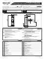
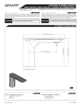
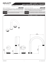
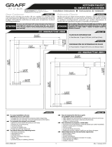
Model
Modelo ME 6104-LM41M
(148mm)
1-3/8”
(35mm)
O
(54mm)
(112mm)
(45mm)
O
(6mm)
(20mm)
O
5-13/16”
2-1/8”
13/16”
1/4”
1-3/4”
4-3/8”
IOG 5038.00
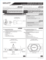
This faucet complies with NSF61/9, ASME/ANSI A112.18.1
and CSA B 125 Standards.
Este grifo se encuentra conforme con losestandares de NSF61/9,
de ASME/ANSI A112.18.1 y de CSA B 125. Installation Instructions Instrucciones de Instalación
LAVATORY & VESSEL FAUCET
MEZCLADORA PARA OVALÍN Y LAVABO DE SOBREPONER
ENGLISH
~
ESPANOL
1
2
3
4
5
6
7
8
9
10
11
12
13
14
15
16
17
1
2
3
4
5
6
7
8
9
10
11
12
13
14
15
16
17
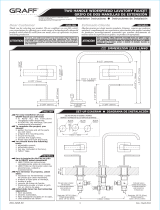
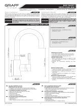
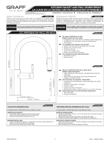
FAUCET BODY
AERATOR INSERT
CARTRIDGE
NUT
CARTRIDGE COVER
LEVER BODY
O-RING SEAL
CUERPO DE LA MEZCLADORA
INSERTO DEL AEREADOR
MEZCLADOR
TUERCA
CUBIERTA DEL MEZCLADOR
CUERPO DE LA PALANCA
EMAPQUETADURA DE ANILLO
ARANDELA DE GOMA
RUBBER WASHER
TUERCA DE MONTAJE
MOUNTING NUT
MANGUERA FLEXIBLE 450 MM
TORNILLO
TORNILLO
TORNILLO
FLEXIBLE HOSE 450MM
BOLT
SCREW
STUD BOLT
ARANDELA DE METAL
METAL WASHER
LEVER BAR
MIXER BASE
BARRA DE LA PALANCA
BASE DE LA MEZCLADORA
18 18 JUNTA TÓRICA O-RING SEAL
COPPER TUBE TUBO DE COBRE
19 19AUTOMATIC DRAIN VALVE DESCARGA CON MANDO A PRESIÓN
20 20 CAÑOSPOUT
Rev. 2 December 2021

1
19
B
A
2
2
IOG 5038.00
This faucet complies with NSF61/9, ASME/ANSI A112.18.1
and CSA B 125 Standards.
Este grifo se encuentra conforme con losestandares de NSF61/9,
de ASME/ANSI A112.18.1 y de CSA B 125. Installation Instructions Instrucciones de Instalación
LAVATORY & VESSEL FAUCET
MEZCLADORA PARA OVALÍN Y LAVABO DE SOBREPONER
17
17
12
13
14
10
18
11
16
16
1
3
7
5
6
4
89
15
23 22
21
20
2
10
11
MAX. 1-3/4"
O1-1/4"
16
13
15
17
14
12
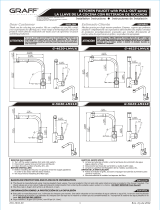
LLAVE ESPECIAL PARA EL AEREADOR
LLAVE ALLEN 2MM
SPECIAL KEY FOR THE AERATOR
2MM HEX KEY
A
B
21 21O-RING SEAL JUNTA TÓRICA
22 22 CONECTORCONNECTOR
23 23O-RING SEAL JUNTA TÓRICA
A
B
Rev. 2 December 2021

ENGLISH
~
ESPANOL
3
This faucet complies with NSF61/ , ASME/ANSI A112.18.1
and CS 2 tandards.
Este grifo se encuentra conforme con losestandares de NSF61/ ,
de ASME/ANSI A112.18.1 y de CS 2 . Installation Instructions Instrucciones de Instalaci n
LA ATOR ESSE AUCET
ME CLADORA PARA O ALÍN Y LA ABO DE SOBREPONER
ENGLISH
ENGLISH
~
ESPANOL
~
ESPANOL
3
3
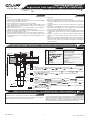
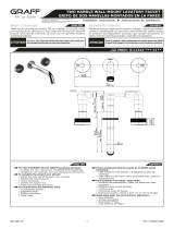
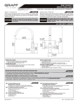
AUTOMATIC DRAIN ASSEMBLY INSTALLATION INSTALACIÓN DEL JUEGO DE DESAGÜE AUTOMATICO
1
2
3
4
5
6
7
8
9
10
DRAIN COLLAR
DRAIN PLUG
UNDER
NUT
TAILPIECE
CUERPO DE DESAG E
ANILLO DE DESAG E
TAPA PROTECTORA
JUEGO DE ALTERNADOR DE DESAG E
JUNTA INFERIOR
JUNTA SUPERIOR DEL ANILLO
ARANDELA
ARANDELA
TUERCA
PIPA DE DESCARGA
Minimum hole in lavatory
Agujero mínimo en el lavabo
- /16"
-1/4"
min.1"-max.1- /16"
See fig. 3
1. Remove drain body with under-bowl et from drain collar .
2. Insert drain collar with collar et , drain plug and drain switch assembly into
drain hole of a lavatory.
3. From underneath the lavatory thread drain body with under et onto drain
collar . tighten only.
4. Insert trap nut and et onto tailpiece and carefully slide trap over tailpiece.
Tighten trap nuts.
er la figura 3
1. el cuerpo de con la junta inferior del anillo de .
2. Colocar el anillo de con la junta del anillo , tapa protectora y el juego de
alternador de en el agujero de del lavabo.
3. Por la parte de abajo del lavabo colocar el cuerpo de con la junta inferior en el
anillo de . Apretar a mano.
4. Colocar la tuerca del y la junta sobre el pipa de descarga y con cuidado deslizar el
sobre el pipa de descarga.
Apretar las tuercas del
1-11/16"
La aperture de la salida de agua y la regulación de su gasto sucede a causa
de bajar la palanca en la superficie vertical. El aumento de la temperature del
agua sucede al tornar la palanca a la izquierda, y la reducción al tornar la
palanca a la derecha. La posición extrema izquierda del mango de la salida
sólo al agua caliente, la extrema derecha la salida sólo del agua fría.
3
~
ESPANOL
ENGLISH
OPERATING INSTRUCTIONS LA DESCRIPCIÓN DEL FUNCIONAMIENTO
The water flow is opened and regulated by lifting the horizontal lever .
The temperature is increased by turning the lever to the left (hot water)
and decreased by turning it to the right (cold water).
IOG 5038.00
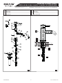
Screw the stud bolt (12) into small hole.
Position base seal (11) in underside cavity of the faucet base (10).
Be sure seal is fully seated in groove.
Place faucetand center over hole of mounting surface .
From underneath the sink/bidet place rubber washer (13), metal
washer (14) on the stud bolt (12), then screw on the mounting nut
(15). Hand tighten only.
Make sure that the faucet is in proper position on the sink/bidet.
Tighten the mounting nut (15) using adjustable wrench.
Please check label on flexible supply hose for identyfication of hot (red
sticker) or cold (blue sticker) water.
Connect flexible hoses (17) to the inlet valves of water supply lines.
Be sure to hold the flexible hoses in place when tightening the nut so
as not twist the hoses. Use adjustable wrench when tightening. Do not
overtighten.
1.
2.
3.
4.
5.
6.
7.
See fig. 2
Atornille el tornillo (12) en el agujero pequeño.
Inserte la arandela de caucho (11) en el rebaje de la base de la
mezcladora (10). Asegúrese de que la arandela quede al ras dentro
del rebaje.
Coloque el batería y centre en el agujero lateral de la superficie de
montaje.
Por debajo del lavabo/bidé coloque la arandela de goma (13),
arandela de metal (14) en el tornillo (12), entonces atornille la
tuerca de montaje (15). Apriete únicamente a mano.
Asegúrese de que el batería se encuentra en la posición apropiada en
el lavabo/bidé. Ajuste la tuerca de montaje (15) usando la llave
inglesa.
Verifique la etiqueta de la manguera flexible suministrada para
identificar si es agua caliente (etiqueta roja) o agua fría (etiqueta
azul).
Conecte las mangueras flexibles (17) a las líneas de fuente de
entrada de agua. Mientras fijas la tuerca, sujeta el tubo flexible para
queno se tuerza. Use la llave ajustable para ajustar las piezas. No
ajuste demasiado.
1.
2.
3.
4.
5.
6.
7.
Ver la figura 2
Rev. 2 December 2021

See fig. 1
1. Remove aerator insert (2) (use the special key (A) supllied) and turn
faucet handle to the full on mixed position.
2. Turn on hot and cold water supply valves and flush water lines for 15
1)
seconds .
3. Check all connections at arrows for leaks. Re-tighten if necessary, but
do not overtighten.
4. Replace aerator insert (2). Use the special key (A).
1) IMPORTANT: This flushes away any debris that could cause damage to
internal parts.
Ver la figura 1
1. Retire el inserto del aereador (2) (use una llave especial A) anexa al
juego) y gire el mango del grifo a la posición de mezclado completo.
2. Abra las válvulas de suministro de agua fría y caliente y enjuague las
1)
lineas de agua por 15 seg. .
3. Chequee todas las conecciones para ver si hjay fuga de agua. Reajuste
si es necesario, pero no ajuste demasiado.
4. Coloque el inserto del aereador (2). Ajuste solo con la llave especial (A).
1) IMPORTANTE: Esto limpia los residuos que podrían causar daño a las
piezas internas con un chorro de agua.
4
AFTER INSTALLATION BEFORE USE
DESPUES DE LA INSTALACIÓN Y ANTES DEL USO
ENGLISH
~
ESPANOL
It is recommended that every 3-6 months (depending on water quality)
you remove the aerator (item 8, fig. 2) from the faucet spout (20) in order
to remove any impurities. For this purpose, use the special key (A)
(supplied).
Una vez a 3-6 meses (dependiendo de la calidad del agua) se recomienda
quitar el difusor (pos. 8 dis. 2) del caño de la mezcladora (20) con el fin de
limpiarlo de todo tipo de ensuciamiento. Para eso use una llave especial
(A) anexa al juego.
ENGLISH
~
ESPANOL
5
CARE AND MAINTENANCE
CUIDADO Y MANTENIMIENTO
Your Graff faucet is designed and engineered in accordance with the
highest quality and performance standards. Be sure not to damage the
finish during installation. Care should be given to the cleaning of this
product. Although its finish is extremely durable, it can be damaged by
harsh abrasives or polish. Never use abrasive cleaners, acids,
solvents, etc. to clean any Graff product. To clean, simply wipe
gently with a damp cloth and blot dry with a soft towel.
Su grifo de la Graff esta diseńado y dirigido acuerdo con los estándares de
funcionamiento y calidad más altos. Este seguro no dańar las terminaciones
del grifo durante la instalación. Cuide el producto manteniendolo siempre
limpio. Aunque su acabado es extremadamente durable, puede ser dańado
por los abrasivos o pulientes ásperos. Nunca utilice limpiadores
abrasivos, ácidos, solventes, el etc. para limpiar cualquier producto
de la Graff. Para limpiar, simplemente use un pańo húmedo y seque
con una toalla suave.
4
ENGLISH
~
ESPANOL
WARRANTY
GARANTÍA
Warranty conditions and warranty registration card are outlined on a
separate sheet.
Las condiciones de la garantía y la tarjeta del registro de la garantía se
encuentran en una pagina separada.
All dimensions and drawings are for reference only. For details, please refer to actual products.
Todas las dimensiones y dibujos sirven únicamente de referencia. Para consultar detalles, ver los productos.
IOG 5038.00
www.graff-designs.com
This faucet complies with NSF61/ , ASME/ANSI A112.18.1
and CS 2 tandards.
Este grifo se encuentra conforme con losestandares de NSF61/ ,
de ASME/ANSI A112.18.1 y de CS 2 . Installation Instructions Instrucciones de Instalaci n
LA ATOR ESSE AUCET
ME CLADORA PARA O ALÍN Y LA ABO DE SOBREPONER
Rev. 2 December 2021
-
 1
1
-
 2
2
-
 3
3
-
 4
4


Graff G-6104-LM41M Guía de instalación
- Categoría
- Artículos sanitarios
- Tipo
- Guía de instalación
En otros idiomas
Documentos relacionados
-
 Graff Faucets G-6300-LM42-PC Guía de instalación
-
 Graff G-5676-LM49D Guía de instalación
-
 Graff G-2311-LM40-SN Guía de instalación
-
 Graff G-11531 Guía de instalación
-
 Graff G-11553 Guía de instalación
-
 Graff G-5230-LM3 Guía de instalación
-
 Graff G-4625-LM41K Guía de instalación
-
 Graff G-5671-LM49D Guía de instalación
-
 Graff G-4866 Guía de instalación
-
 Graff G-4612-LM3 Guía de instalación