Efco DR 50 K800H El manual del propietario
- Categoría
- Herramientas de jardín
- Tipo
- El manual del propietario


1
5
10
13
12
98
6
10
11
6
7
4
10
2
3
1
1
2
3
4
7
5 6
10
8
9
12
14
16
17
15
18
Type: XXXXX
kW: XX
Kg: XXX
XXXX min-1
B340000000 2021
A B C D
A
E F G
B C
D
13
A B
C D
2

2
3

3
4
5
476 mm
877 mm
556 mm
1026 mm
1185 mm571 mm
543 mm
672 mm
1555 mm
550 mm
BA
4

6
7 8
2
1
B
A
AA
BB
5

9
10
11 12
1
2
1
2
1
6

13
14
15
16
17
18
3
2
1
N
1R
15°
4
3
1
2
0.7-0.8 mm (0.028”-0.031”)
7

19
8

ITALIANO - Istruzioni Originali .....................................................................................10
ENGLISH - Translation of the original instructions ................................................................43
FRANÇAIS - Traduction de la notice originale .....................................................................75
DEUTSCH - Übersetzung der Originalanleitungen ............................................................... 109
ESPAÑOL - Traducción de las instrucciones originales .......................................................... 143
POLSKI - Tłumaczenie oryginalnych instrukcji ................................................................... 176
9

IT
1 INTRODUZIONE ............................................................................................... 12
1.1COMELEGGEREILMANUALE..............................................................................12
2 NORME DI SICUREZZA . . . .. . . ... . ... . . .. . . .. . . .. . . .. . . .. . .. . . ... . . .. . . .. . . .. . . .. . . .. . . .. . ... . . .. . . .. . . .. . . .. . 13
2.1USOPREVISTO..............................................................................................15
2.2USOSCORRETTO ...........................................................................................15
2.3RISCHIRESIDUI..............................................................................................15
2.4 DISPOSITIVI DI PROTEZIONE INDIVIDUALE (DPI) . . . . . . . . . . . . . . . . . . . . . . . . . . . . . . . . . . . . . . . . . . . . . . . . . . . . . . . . . .16
3 SIMBOLI E AVVERTENZE DI SICUREZZA (FIG. 1) . . .. . .. . . .. . . .. . . .. . . .. . . .. . . ... . . .. . .. . . .. . . .. . . .. . . .. . . 17
4 COMPONENTI PRINCIPALI.. . .. . . .. . . .. . . ... . . .. . . .. . . .. . .. . . .. . . .. . . ... . . .. . . .. . . .. . . .. . .. . . .. . . ... . ... . . .. . 18
5ASSEMBLAGGIO............................................................................................... 18
5.1 MONTAGGIO MANUBRIO (FIG. 4) . . . . . . . . . . . . . . . . . . . . . . . . . . . . . . . . . . . . . . . . . . . . . . . . . . . . . . . . . . . . . . . . . . . . . . . . . .18
6 DISPOSITIVI DI SICUREZZA E COMANDI . .. . . .. . . .. . . .. . . .. . . .. . . .. . . .. . . .. . . .. . . .. . . .. . . ... . .. . . .. . . .. . . . 18
6.1 DISPOSITIVI DI SICUREZZA . . . . . . . . . . . . . . . . . . . . . . . . . . . . . . . . . . . . . . . . . . . . . . . . . . . . . . . . . . . . . . . . . . . . . . . . . . . . . . . . .18
6.1.1 PROTEZIONE ANTERIORE (1, FIG. 10) . . . . . . . . . . . . . . . . . . . . . . . . . . . . . . . . . . . . . . . . . . . . . . . . . . . . . . . . . . . . . . .18
6.1.2 DISPOSITIVI DI SICUREZZA SULLE LEVE (5, FIG. 2) . . . . . . . . . . . . . . . . . . . . . . . . . . . . . . . . . . . . . . . . . . . . . . . . .19
6.1.3 FRENO DI STAZIONAMENTO. . . . . . . . . . . . . . . . . . . . . . . . . . . . . . . . . . . . . . . . . . . . . . . . . . . . . . . . . . . . . . . . . . . . . . . .19
6.2COMANDI...................................................................................................19
6.2.1 INTERRUTTORE MOTORE ON/OFF (7, FIG. 2) . . . . . . . . . . . . . . . . . . . . . . . . . . . . . . . . . . . . . . . . . . . . . . . . . . . . . . .19
6.2.2 LEVETTA STARTER (12, FIG. 2). . . . . . . . . . . . . . . . . . . . . . . . . . . . . . . . . . . . . . . . . . . . . . . . . . . . . . . . . . . . . . . . . . . . . . .19
6.2.3 LEVA FLUSSO CARBURANTE ON/OFF (13, FIG. 2) . . . . . . . . . . . . . . . . . . . . . . . . . . . . . . . . . . . . . . . . . . . . . . . . . .19
6.2.4 COMANDO ACCELERATORE (6, FIG. 2) . . . . . . . . . . . . . . . . . . . . . . . . . . . . . . . . . . . . . . . . . . . . . . . . . . . . . . . . . . . . .19
6.2.5 LEVA INNESTO DISPOSITIVO DI TAGLIO (4, FIG. 2). . . . . . . . . . . . . . . . . . . . . . . . . . . . . . . . . . . . . . . . . . . . . . . . .19
6.2.6 LEVA FRIZIONE AVANZAMENTO MACCHINA (3, FIG. 2) . . . . . . . . . . . . . . . . . . . . . . . . . . . . . . . . . . . . . . . . . . .20
6.2.7 LEVA SELETTORE MARCE (9, FIG. 2). . . . . . . . . . . . . . . . . . . . . . . . . . . . . . . . . . . . . . . . . . . . . . . . . . . . . . . . . . . . . . . . .20
6.2.8 LEVE DI STERZATURA (1, 2, FIG. 2) . . . . . . . . . . . . . . . . . . . . . . . . . . . . . . . . . . . . . . . . . . . . . . . . . . . . . . . . . . . . . . . . . .20
7 OPERAZIONI PRELIMINARI . . ... . . .. . . .. . . .. . . .. . . .. . . .. . ... . . .. . . .. . . .. . . .. . . .. . . .. . . .. . ... . . .. . . .. . . .. . . .. . 21
7.1AREADILAVORO...........................................................................................21
7.2 REGOLAZIONE DEL MANUBRIO (FIG. 5) . . . . . . . . . . . . . . . . . . . . . . . . . . . . . . . . . . . . . . . . . . . . . . . . . . . . . . . . . . . . . . . . . . .21
7.3 REGOLAZIONE ALTEZZA TAGLIO . . . . . . . . . . . . . . . . . . . . . . . . . . . . . . . . . . . . . . . . . . . . . . . . . . . . . . . . . . . . . . . . . . . . . . . . . .21
8AVVIAMENTO.................................................................................................. 22
8.1CARBURANTE...............................................................................................22
8.2RIFORNIMENTO.............................................................................................22
8.3 PROCEDURA DI AVVIAMENTO . . . . . . . . . . . . . . . . . . . . . . . . . . . . . . . . . . . . . . . . . . . . . . . . . . . . . . . . . . . . . . . . . . . . . . . . . . . . .23
8.4MOTOREINGOLFATO.......................................................................................25
9 ARRESTO MOTORE. .. . .. . . .. . .. . .. . .. . .. . .. . . .. . .. . .. . . .. . .. . .. . .. . . .. . .. . .. . .. . .. . . .. . .. . .. . . .. . .. . .. . .. . .. . . 25
10 UTILIZZO DELLA MACCHINA . .. .. .. . .. .. .. . .. .. .. . .. .. .. . .. .. .. . .. .. .. . .. .. .. . .. .. .. . .. .. .. . .. .. .. . .. .. .. . 25
10.1 CONTROLLI DI SICUREZZA . . . . . . . . . . . . . . . . . . . . . . . . . . . . . . . . . . . . . . . . . . . . . . . . . . . . . . . . . . . . . . . . . . . . . . . . . . . . . . . .25
10.2PRECAUZIONIGENERALI..................................................................................26
10.3LAVORO....................................................................................................27
10.4TAGLIODELL’ERBA........................................................................................28
11 MANUTENZIONE ............................................................................................ 30
11.1 CONFORMITÀ DELLE EMISSIONI GASSOSE. . . . . . . . . . . . . . . . . . . . . . . . . . . . . . . . . . . . . . . . . . . . . . . . . . . . . . . . . . . . . . .30
11.2 SOSTITUZIONE DELL’OLIO MOTORE. . . . . . . . . . . . . . . . . . . . . . . . . . . . . . . . . . . . . . . . . . . . . . . . . . . . . . . . . . . . . . . . . . . . . .31
11.3 PULIZIA E SOSTITUZIONE DEL FILTRO DELL’ARIA . . . . . . . . . . . . . . . . . . . . . . . . . . . . . . . . . . . . . . . . . . . . . . . . . . . . . . .31
11.4 SOSTITUZIONE DELLA CANDELA . . . . . . . . . . . . . . . . . . . . . . . . . . . . . . . . . . . . . . . . . . . . . . . . . . . . . . . . . . . . . . . . . . . . . . . . .32
11.5 MANUTENZIONE STRAORDINARIA . . . . . . . . . . . . . . . . . . . . . . . . . . . . . . . . . . . . . . . . . . . . . . . . . . . . . . . . . . . . . . . . . . . . . . .33
11.6 TABELLA DI MANUTENZIONE. . . . . . . . . . . . . . . . . . . . . . . . . . . . . . . . . . . . . . . . . . . . . . . . . . . . . . . . . . . . . . . . . . . . . . . . . . . . .33
10

IT
12 MOVIMENTAZIONE E TRASPORTO . .. . . ... . . .. . . .. . . .. . . .. . . .. . . .. . .. . . ... . . .. . . .. . . .. . . .. . . .. . . .. . . .. . . . 34
12.1MOVIMENTAZIONE........................................................................................34
12.2TRASPORTO ...............................................................................................35
13 RIMESSAGGIO................................................................................................ 35
13.1 PULIZIA DELLA MACCHINA . . . . . . . . . . . . . . . . . . . . . . . . . . . . . . . . . . . . . . . . . . . . . . . . . . . . . . . . . . . . . . . . . . . . . . . . . . . . . . .36
13.2 RIMESSAGGIO PROLUNGATO. . . . . . . . . . . . . . . . . . . . . . . . . . . . . . . . . . . . . . . . . . . . . . . . . . . . . . . . . . . . . . . . . . . . . . . . . . . . .36
13.3 RIMESSA IN SERVIZIO DOPO LO STOCCAGGIO . . . . . . . . . . . . . . . . . . . . . . . . . . . . . . . . . . . . . . . . . . . . . . . . . . . . . . . . . .37
14 TUTELA AMBIENTALE. . . .. . . .. . . .. . . .. . . .. . . ... . . .. . . .. . .. . . .. . . .. . . .. . . ... . . .. . . .. . . .. . .. . . .. . . .. . . .. . . ... . 37
14.1 DEMOLIZIONE E SMALTIMENTO. . . . . . . . . . . . . . . . . . . . . . . . . . . . . . . . . . . . . . . . . . . . . . . . . . . . . . . . . . . . . . . . . . . . . . . . . .37
15 DATITECNICI................................................................................................. 38
15.1 CARATTERISTICHE MACCHINA. . . . . . . . . . . . . . . . . . . . . . . . . . . . . . . . . . . . . . . . . . . . . . . . . . . . . . . . . . . . . . . . . . . . . . . . . . . .38
15.2 EMISSIONI ACUSTICHE E VIBRAZIONI . . . . . . . . . . . . . . . . . . . . . . . . . . . . . . . . . . . . . . . . . . . . . . . . . . . . . . . . . . . . . . . . . . . .38
16 DICHIARAZIONE DI CONFORMITÁ. . .. . .. . .. . .. .. . . .. . . .. . .. . .. . .. . .. .. . .. . .. . .. . .. .. . .. . .. . .. . .. .. . . .. . . . 39
17 CERTIFICATO DI GARANZIA . . .. . . .. . .. . . .. . . ... . . .. . . .. . . .. . . .. . . .. . .. . . .. . . ... . . .. . . .. . . .. . . .. . . .. . . .. . .. 40
18 RISOLUZIONE DEI PROBLEMI. .. . . .. . .. . . .. . . .. . . .. . . ... . . .. . . .. . . .. . .. . . .. . . .. . . ... . . .. . . .. . . .. . . .. . . .. . .. 41
11

IT
1 INTRODUZIONE
Grazie per aver scelto un prodotto Emak.
La nostra rete di rivenditori e officine autorizzate sono a Sua completa disposizione per qualsiasi
necessità.
ATTENZIONE
Per un corretto impiego della macchina e per evitare incidenti, non iniziare il lavoro
senza aver letto questo manuale con la massima attenzione.
ATTENZIONE
Questo manuale deve accompagnare la macchina durante tutta la sua vita.
ATTENZIONE
RISCHIO DI DANNO UDITIVO. Nelle normali condizioni di utilizzo, questa macchina
può comportare per l’operatore addetto, un livello di esposizione personale e
giornaliero a rumore pari o superiore a 85 dB (A).
Su questo manuale sono indicate le spiegazioni di funzionamento dei vari componenti e le
istruzioni per i necessari controlli e per la manutenzione.
NOTA
Le descrizioni e le illustrazioni contenute nel presente manuale si intendono non
rigorosamente impegnative. Il costruttore si riserva il diritto di apportare eventuali
modifiche senza impegnarsi ad aggiornare di volta in volta questo manuale.
Le figure sono indicative. I componenti effettivi possono variare rispetto a quelli
raffigurati. In caso di dubbio contattare un Centro Assistenza Autorizzato.
1.1 COME LEGGERE IL MANUALE
Il manuale è diviso in capitoli e paragrafi. Ogni paragrafo è un sottolivello del capitolo di
attinenza. I riferimenti a capitoli o paragrafi sono segnalati con la dicitura “capitolo” o
“paragrafo” seguita dal numero relativo. Esempio: “capitolo 2”.
Oltre alle istruzioni per l’uso e la manutenzione, questo manuale contiene informazioni che
richiedono un’attenzione particolare. Tali informazioni sono contrassegnate dai simboli descritti
di seguito:
ATTENZIONE
Quando sussiste il rischio di incidenti o lesioni personali, anche mortali, o gravi
danni alle cose.
CAUTELA
Quando sussiste il rischio di danni alla macchina o a singoli componenti della stessa.
12

IT
NOTA
Fornisce un’informazione aggiuntiva alle istruzioni dei messaggi di sicurezza precedenti.
Le figure in queste istruzioni per l’uso sono numerate 1, 2, 3, e così via. I componenti indicati
nelle figure sono contrassegnati con lettere o numeri, a seconda del caso. Un riferimento al
componente C nella figura 2 viene indicato con la dicitura: "Vedere C, Fig. 2" o semplicemente
"(C, Fig. 2)". Un riferimento al componente 2 nella figura 1 viene indicato con la dicitura: "Vedere
2, Fig. 1" o semplicemente "(2, Fig. 1)".
2 NORME DI SICUREZZA
ATTENZIONE
La macchina, se ben usata, è uno strumento di lavoro rapido, comodo ed efficace. Se
usata in modo non corretto o senza le dovute precauzioni potrebbe diventare un
attrezzo pericoloso. Perché il vostro lavoro sia sempre piacevole e sicuro, rispettare
scrupolosamente le norme di sicurezza riportate qui di seguito e nel corso del
manuale.
ATTENZIONE
Il sistema di accensione della macchina, produce un campo elettromagnetico di
intensità molto bassa. Questo campo può interferire con alcuni pacemaker. Per
ridurre il rischio di lesioni gravi o mortali, le persone con pacemaker dovrebbero
consultare il proprio medico e il fabbricante del pacemaker prima di utilizzare
questa macchina.
ATTENZIONE
L’esposizione alle vibrazioni provocate dall’uso prolungato di strumenti azionati da
motori a combustione interna può causare lesioni ai vasi sanguigni o ai nervi delle
dita, delle mani e dei polsi nelle persone soggette a disturbi circolatori o gonfiori
anomali. L’uso prolungato in condizioni di bassa temperatura è stato associato alla
lesione dei vasi sanguigni negli individui altrimenti sani. Se si manifestano sintomi
quali insensibilità, dolore, perdita di forza, variazioni nel colore o nella consistenza
della cute o perdita del tatto nelle dita, nelle mani o nei polsi, interrompere l’uso
della macchina e richiedere il parere di un medico.
NOTA
Regolamenti nazionali possono limitare l’uso della macchina.
• Non utilizzare la macchina prima di essere istruiti in modo specifico sul suo uso. L’operatore
alla prima esperienza deve esercitarsi prima dell’utilizzo sul campo.
• La macchina deve essere usata solo da persone adulte, in buone condizioni fisiche e a
conoscenza delle norme d’uso.
• Non usare la macchina in condizioni di affaticamento fisico o sotto l’effetto di alcool, droghe
o farmaci.
• Indossare abiti adatti e dispositivi di sicurezza quali stivali, pantaloni robusti, guanti, occhiali
protettivi, cuffie antirumore e casco antinfortunistico.
• Usare vestiario aderente ma comodo.
13

IT
• Non permettere ai bambini di usare la macchina.
• Non permettere mai che la macchina sia usata da persone con ridotte capacità fisiche,
sensoriali o mentali, o prive di esperienza o della necessaria conoscenza o da persone che
non abbiano la necessaria dimestichezza con le istruzioni.
• Non permettere ad altre persone di restare nel raggio di 15 metri durante l’uso della
macchina.
• Prima di usare la macchina verificare che il manubrio sia ben stretto (3 SIMBOLI E
AVVERTENZE DI SICUREZZA (Fig. 1)).
ATTENZIONE
La macchina deve essere equipaggiata con i dispositivi di taglio originali consigliati
dal Fabbricante. L’uso di dispositivi non autorizzati può condurre a lesioni gravi o
mortali.
• Prima di avviare il motore accertarsi che il dispositivo di taglio sia libero di girare e non sia a
contatto con corpi estranei.
• Usare la macchina solo in luoghi ben ventilati, non utilizzare in atmosfera esplosiva,
infiammabile o in ambienti chiusi.
• Con motore in moto non fare alcuna manutenzione e non toccare il dispositivo di taglio.
• È proibito applicare alla presa di forza della macchina alcun dispositivo che non sia quello
fornito dal Fabbricante.
• Non lavorare con una macchina danneggiata, mal riparata, mal montata o modificata
arbitrariamente.
• Non rimuovere, danneggiare o rendere inefficace alcun dispositivo di sicurezza.
• Mantenere tutte le etichette con i segnali di pericolo e di sicurezza in perfette condizioni. In
caso di danneggiamenti o deterioramenti occorre sostituirle tempestivamente (3 SIMBOLI E
AVVERTENZE DI SICUREZZA (Fig. 1)).
• Non utilizzare la macchina per usi diversi da quelli indicati dal presente manuale (vedi
capitolo 2.1 USO PREVISTO).
• Non abbandonare la macchina con il motore acceso.
• Controllare giornalmente la macchina per assicurarsi che ogni dispositivo, di sicurezza e non,
sia funzionante.
• Non effettuare operazioni o riparazioni che non siano di normale manutenzione. Per ogni
altro intervento, rivolgersi ad un Centro Assistenza Autorizzato.
• In caso di necessità di messa fuori servizio della macchina, non abbandonarla nell’ambiente,
ma consegnarla al Rivenditore che provvederà alla sua corretta collocazione.
• Il manuale fa parte integrante della macchina, deve seguirla sempre in tutti cambi di
proprietà anche temporanei.
• Rivolgetevi sempre al vostro Rivenditore o Centro Assistenza Autorizzato per qualsiasi altro
chiarimento o intervento prioritario.
• Conservare con cura il seguente Manuale e consultarlo prima di ogni utilizzo della macchina.
• Ricordare che il proprietario o l’operatore è responsabile degli incidenti o dei rischi subiti da
terzi o da beni di loro proprietà.
14

IT
ATTENZIONE
• Non utilizzare mai una macchina con funzioni di sicurezza difettose. Le funzioni
di sicurezza della macchina devono essere sottoposte a verifica e manutenzione
in base alle istruzioni fornite al capitolo 10.1 CONTROLLI DI SICUREZZA e al
capitolo 11 MANUTENZIONE. Se la macchina non supera queste verifiche,
rivolgersi a un Centro Assistenza Autorizzato per farla riparare.
• Ogni uso della macchina non previsto espressamente nel manuale può essere
fonte di rischi per persone e cose, pertanto è da considerarsi come uso improprio
ed espressamente vietato dal Fabbricante, che declina ogni responsabilità sui
danni conseguenti.
2.1 USO PREVISTO
Questa macchina è progettata e costruita esclusivamente per:
• il taglio di erbe alte, sterpi e rovi;
• tritatura fina di erba, sterpi e rovi mediante l’ausilio del dispositivo di taglio a flagelli rotanti;
• essere utilizzata da un solo operatore.
2.2 USO SCORRETTO
Tutti gli usi non compresi al capitolo 2.1 USO PREVISTO sono da considerarsi usi scorretti ed in
particolare, ma non esclusivamente, i seguenti:
ATTENZIONE
Il dispositivo di taglio può scagliare oggetti e piccoli sassi causando danni o
provocando lesioni a persone. La zona di sicurezza intorno alla macchina è fissata in
15 metri.
• taglio di materiali di origine non vegetale;
• impiego di dispositivi di taglio diversi da quelli raccomandati dal Fabbricante;
• utilizzo della macchina come mezzo di trasporto di persone o cose.
2.3 RISCHI RESIDUI
Nonostante la cura adottata dal Fabbricante nel rispetto di tutte le prescrizioni di sicurezza,
permane la sussistenza di rischi residui che non possono essere eliminati, tra i quali ad esempio:
• Proiezioni di materiali che possono lesionare gli occhi, se non vengono indossate adeguate
protezioni.
• Lesione dell’udito, se non viene indossata nessuna protezione acustica.
• Contatto con parti calde.
• Caduta dell’operatore.
15

IT
2.4 DISPOSITIVI DI PROTEZIONE INDIVIDUALE (DPI)
Per dispositivo di protezione individuale (DPI) si intende qualsiasi attrezzatura destinata ad
essere indossata dall’operatore allo scopo di proteggerlo contro i rischi per la sicurezza o la
salute durante il lavoro, nonché ogni dispositivo o accessorio destinato a tale scopo. L’uso dei
DPI non elimina il pericolo di lesione, ma riduce gli effetti del danno in caso di incidente.
Di seguito è riportato l’elenco dei dispositivi di protezione individuale da utilizzare durante l’uso
della macchina:
•Indossare scarpe di sicurezza antitaglio munite di suole antisdrucciolo e puntali
d’acciaio.
•Indossare gli occhiali o la visiera protettivi.
•Applicare protezioni dai rumori; per esempio le cuffie o i tappi.
ATTENZIONE
L’uso delle protezioni per l’udito richiede maggior attenzione e prudenza,
perché la percezione di segnali acustici di pericolo (grida, allarmi, ecc.) è limitata.
•Calzare guanti che permettano il massimo assorbimento delle vibrazioni.
•Indossare abbigliamento protettivo di sicurezza omologato. La giacca e la salopette di
protezione sono l’ideale.
ATTENZIONE
L’abbigliamento deve essere adatto e non d’impaccio. Indossare un abito aderente
protettivo. Non portare abiti, sciarpe, cravatte o monili che potrebbero impigliarsi
nella macchina, nella sterpaglia o altro. Raccogliere i capelli lunghi e proteggerli.
NOTA
Fatevi consigliare dal vostro rivenditore di fiducia per la scelta dell’abbigliamento
adeguato.
16

IT
3 SIMBOLI E AVVERTENZE DI SICUREZZA (FIG. 1)
In figura sono riportati i simboli e le avvertenze di sicurezza presenti sulla macchina:
1. Innesto dispositivo di taglio.
2. Comando frizione.
3. Comando acceleratore.
4. Comando freno.
5. Leggere il libretto uso e manutenzione prima di utilizzare la macchina.
6. Pericolo di impigliamento.
7. Pericolo superfici calde/incendio.
8.A Pericolo generico.
Non utilizzare la macchina in presenza di bambini.
8.B Obbligo di leggere il manuale prima di utilizzare la macchina.
Durante l’uso, assicurarsi che nessuno si avvicini al dispositivo di taglio. Pericolo di taglio arti
inferiori.
8.C Pericolo proiezione oggetti.
Durante l’uso assicurarsi che l’area di lavoro sia sgombra da estranei entro un raggio di 15 m.
8.D Pericolo taglio arti superiori.
STOP: fermare il dispositivo di taglio.
9.A Obbligo di indossare la mascherina/protezione per le vie respiratorie.
9.B Obbligo di indossare gli occhiali protettivi.
9.C Obbligo di leggere il manuale.
9.D Obbligo di indossare i guanti per assorbire le vibrazioni.
9.E Obbligo di indossare un dispositivo di protezione acustica.
9.F Divieto di indossare cravatte, monili o altri capi d’abbigliamento svolazzanti che potrebbero
impigliarsi nelle sterpaglie o nei meccanismi della macchina.
9.G Obbligo di indossare calzature protettive antiscivolo.
10. Pericolo di taglio/cesoiamento arti inferiori.
11. Marce.
12. Levetta Starter CHIUSA.
13.A Levetta Starter APERTA.
13.B Leva flusso carburante OFF.
13.C Leva flusso carburante ON.
14. Tipo di macchina: TRINCIATUTTO.
15. Marcatura CE di conformità.
16. Numero di serie.
17. Anno di fabbricazione.
18. Dati tecnici.
17

IT
4 COMPONENTI PRINCIPALI
In Fig. 2 sono mostrati i componenti principali della macchina:
1. Leva sbloccaggio ruota sinistra
2. Leva sbloccaggio ruota destra
3. Leva frizione avanzamento macchina
4. Leva innesto dispositivo di taglio
5. Pulsante di sicurezza
6. Comando acceleratore
7. Interruttore motore ON/OFF
8. Leva regolazione manubrio
9. Leva selettore marce
10. Leva regolazione altezza taglio
11. Dispositivo di taglio a flagelli rotanti
12. Levetta Starter
13. Leva flusso carburante ON/OFF
14. Maniglia avviamento motore
15. Tappo serbatoio carburante
16. Tappo controllo livello olio
17. Bullone di scarico olio
18. Dado ad alette filtro aria
5 ASSEMBLAGGIO
ATTENZIONE
Durante le operazioni di assemblaggio indossare sempre i guanti protettivi.
5.1 MONTAGGIO MANUBRIO (FIG. 4)
La macchina viene fornita montata, fatta eccezione per il manubrio che prima dell’utilizzo deve
essere fissato al telaio attraverso le viti indicate in Fig. 4.
CAUTELA
Verificare che tutti i componenti della macchina siano ben collegati e le viti serrate.
NOTA
Seguire scrupolosamente le norme locali per lo smaltimento degli imballi.
6 DISPOSITIVI DI SICUREZZA E COMANDI
6.1 DISPOSITIVI DI SICUREZZA
La macchina è dotata dei seguenti dispositivi di sicurezza.
6.1.1 Protezione anteriore (1, Fig. 10)
La protezione anteriore (Fig. 10) è una protezione basculante automaticamente richiudibile per
gravità. La sua funzione è quella di bloccare il lancio di oggetti durante le fasi di raccolta.
18

IT
ATTENZIONE
Non utilizzare mai la macchina con la protezione bloccata (Fig. 10) o con la
protezione smontata. Questo potrebbe aumentare la proiezione di oggetti verso
l’esterno.
6.1.2 Dispositivi di sicurezza sulle leve (5, Fig. 2)
Sulle leve dei comandi di inserimento trazione (3, Fig. 2) e di innesto del dispositivo di taglio (4,
Fig. 2) è presente un dispositivo di sicurezza (5, Fig. 2) contro l’avviamento accidentale che
impedisce l’azionamento delle leve con una sola mano (Fig. 8).
6.1.3 Freno di stazionamento
Sulla macchina è presente un freno sempre inserito che ha la funzione di freno di
stazionamento e che viene disattivato quando si inserisce la trazione (3, Fig. 2) alla macchina. In
caso di rilascio della leva di trazione la macchina si ferma.
6.2 COMANDI
La macchina è dotata dei seguenti comandi.
6.2.1 Interruttore motore on/off (7, Fig. 2)
L’interruttore motore ON/OFF (7, Fig. 2) abilita il motore all’avviamento (posizione ON) o ne
arresta il funzionamento (posizione OFF).
6.2.2 Levetta starter (12, Fig. 2)
La levetta Starter (12, Fig. 2) consente di predisporre il motore per l’avviamento e può essere
portata su due posizioni: APERTA (13, 2, Fig. 2), per predisporre il motore riscaldato
all’avviamento, o CHIUSA (1, 13, Fig. 2), per predisporre il motore non riscaldato all’avviamento.
6.2.3 Leva flusso carburante on/off (13, Fig. 2)
La leva flusso carburante ON/OFF (13, Fig. 2) regola il passaggio del combustibile e può essere
portata su due posizioni: ON (4, 13, Fig. 2), per consentire il passaggio del combustibile, o OFF
(3, 13, Fig. 2) per arrestarne invece il flusso.
6.2.4 Comando acceleratore (6, Fig. 2)
Il comando acceleratore (6, Fig. 2) consente di regolare l’accelerazione della macchina.
6.2.5 Leva innesto dispositivo di taglio (4, Fig. 2)
La leva innesto dispositivo di taglio (4, Fig. 2) consente di avviare il dispositivo di taglio. Per
l’attivazione della leva è necessario utilizzare entrambe le mani e procedere come descritto di
seguito:
1. Premere il pulsante di sicurezza (1, Fig. 11) con una mano.
2. Abbassare la leva (2, Fig. 11) con l’altra mano.
19

IT
ATTENZIONE
Accertarsi che non ci siano persone vicino al dispositivo di taglio quando è in
funzione (Fig. 9).
Il rilascio della leva provoca l’arresto del dispositivo di taglio.
6.2.6 Leva frizione avanzamento macchina (3, Fig. 2)
La leva frizione avanzamento (3, Fig. 2) consente alla macchina di procedere avanti o indietro a
seconda della marcia innestata. Se il selettore delle marce (9, Fig. 2) è nella posizione di folle N
(N, Fig. 13) la macchina è ferma.
Per l’attivazione della leva è necessario utilizzare entrambe le mani e procedere come descritto
di seguito:
1. Premere il pulsante di sicurezza (1, Fig. 12) con una mano.
2. Abbassare la leva (2, Fig. 12) con l’altra mano.
ATTENZIONE
Prima di inserire la leva di avanzamento (3, Fig. 2), verificare sempre che la marcia
sia inserita. In caso di emergenza, rilasciare la leva di avanzamento per fermare
immediatamente la macchina.
6.2.7 Leva selettore marce (9, Fig. 2)
La leva selettore marce (9, Fig. 2) consente di impostare la marcia della macchina. È possibile
impostare 3 differenti marce in avanti (velocità massima di 3,4 Km/h), la retromarcia (1,4 km/h) e
la posizione folle (N, Fig. 13).
ATTENZIONE
Per evitare danni alla trasmissione è necessario rilasciare sempre la leva frizione
avanzamento (3, Fig. 2) quando si cambia la marcia.
6.2.8 Leve di sterzatura (1, 2, Fig. 2)
Le due leve di sterzatura (1, 2, Fig. 2) sono posizionate nella parte inferiore dell’impugnatura
della stegola sinistra e della stegola destra e la loro funzione è quella di consentire il cambio di
direzione alla macchina. Rilasciando la leva di destra si blocca la ruota di destra e la macchina
sterza a destra; rilasciando la leva di sinistra si blocca la ruota di sinistra e la macchina sterza a
sinistra.
Rilasciando completamente entrambe le leve si bloccano entrambe le ruote e la macchina si
ferma. Se entrambe le leve vengono premute fino a metà corsa, disattivano il freno di
stazionamento sempre attivato e consentono di movimentare la macchina con motore spento.
ATTENZIONE
Prestare attenzione se si lavora in pendenza (Fig. 15). In caso di pericolo dovuto alla
perdita di controllo della macchina, rilasciare tutte le leve azionate.
20

IT
7 OPERAZIONI PRELIMINARI
7.1 AREA DI LAVORO
ATTENZIONE
Ispezionare a fondo tutta l’area di lavoro e rimuovere tutto ciò che potrebbe venire
scagliato dalla macchina o danneggiare il dispositivo di taglio.
7.2 REGOLAZIONE DEL MANUBRIO (FIG. 5)
Prima di utilizzare la macchina è opportuno regolare l’altezza (A, Fig. 5) e la posizione laterale (B,
Fig. 5) del manubrio in base alla propria statura e alla natura del terreno (pianeggiante o
collinare) in modo da assicurare condizioni il più possibile confortevoli per l’operatore.
Regolazione verticale (Fig. 2)
Per una corretta regolazione verticale del manubrio è necessario:
1. Allentare il dado di fissaggio (5, Fig. 2) posto sotto la leva di regolazione (2, Fig. 2).
2. Ruotare il manubrio (A, Fig. 2) attraverso la leva verso l’alto o il basso a seconda
dell’esigenza.
3. Bloccare il manubrio in una delle 4 posizioni stringendo il dado di fissaggio (1, Fig. 2).
Regolazione laterale (Fig. 6)
Per una corretta regolazione laterale del manubrio è necessario:
1. Allentare il dado di fissaggio (1, Fig. 6) posto sotto la leva di regolazione (2, Fig. 6).
2. Ruotare il manubrio (B, Fig. 6) attraverso la leva verso destra o sinistra a seconda
dell’esigenza.
3. Bloccare il manubrio in una delle 7 posizioni stringendo il dado di fissaggio (1, Fig. 6).
ATTENZIONE
Se si prevede di lavorare per diverse ore, regolare il manubrio in modo che la
schiena rimanga sempre in posizione eretta e mai sotto sforzo
7.3 REGOLAZIONE ALTEZZA TAGLIO
In base all’altezza dell’erba da tagliare è necessario regolare l’altezza di taglio ruotando in senso
orario o antiorario l’apposita leva di regolazione (10, Fig. 2), la quale consente di alzare o
abbassare il dispositivo di taglio.
ATTENZIONE
In caso di accumulo di erba e terra all’interno del carter del dispositivo di taglio,
fermare la macchina, spegnere il motore, staccare la candela e procedere alla pulizia
della lama e del carter.
21

IT
8 AVVIAMENTO
ATTENZIONE
• La benzina è un combustibile estremamente infiammabile. Usare estrema
cautela durante la sua manipolazione. Non fumare o portare fiamme libere o
scintille vicino al combustibile o alla macchina.
• Controllare di frequente le tubazioni del carburante, il serbatoio, il tappo e i
raccordi per verificare che non vi siano crepe o perdite. Se necessario contattare
un Centro Assistenza Autorizzato.
8.1 CARBURANTE
Questa macchina è azionata da un motore a 4 tempi e richiede benzina super senza piombo
"fresca" e pulita con un numero minimo di ottani alla pompa di 89.
ATTENZIONE
• Il motore è omologato per il funzionamento con benzina senza piombo. La
benzina senza piombo genera meno incrostazioni nel motore e sulla candela e
prolunga la durata dell’impianto di scarico.
• Non utilizzare mai benzina stantia o sporca o miscele olio/benzina. Evitare
l’introduzione di sporco o acqua nel serbatoio del combustibile.
• Per rallentare il deterioramento del combustibile, conservare la benzina in un
recipiente certificato per carburanti.
• Se si prevede un rimessaggio prolungato (più di 1 mese), svuotare il serbatoio
del combustibile e il carburatore (vedi paragrafo 13.2 RIMESSAGGIO
PROLUNGATO).
• Non usare benzina contenente più del 10% di etanolo.
• Se si decidesse di fare uso di benzina contenente alcool, controllare che abbia un
numero di ottani almeno pari a quello raccomandato.
• Non utilizzare benzina contenente metanolo.
• Non utilizzare fluidi di avviamento pressurizzati.
8.2 RIFORNIMENTO
1. Mettere il combustibile in un contenitore approvato per il carburante.
2. Posizionare la macchina all’aperto su di un terreno sgombro.
3. Arrestare il motore e lasciarlo raffreddare per almeno 2 minuti prima di effettuare il
rifornimento.
4. Pulire la superficie attorno al tappo del carburante (15, Fig. 2) per evitare contaminazioni.
5. Allentare il tappo del carburante (15, Fig. 2) lentamente per rilasciare la pressione e per
evitare la fuoriuscita di combustibile.
6. Versare con attenzione il combustibile nel serbatoio prestando attenzione a evitare
versamenti.
22

IT
ATTENZIONE
Non riempire eccessivamente il serbatoio del carburante. Riempire il serbatoio
fino a circa 4 cm sotto il bordo superiore del bocchettone per consentire
l’espansione del combustibile.
7. Pulire e controllare la guarnizione.
8. Serrare saldamente il tappo carburante (15, Fig. 2) dopo il rifornimento.
ATTENZIONE
Le vibrazioni possono causare un allentamento del tappo e la fuoriuscita di
combustibile.
9. Asciugare il combustibile fuoriuscito dalla macchina. Spostare la macchina a 3 metri di
distanza dal sito di rifornimento prima di avviare il motore.
ATTENZIONE
• Non tentare mai di bruciare combustibile fuoriuscito in qualsiasi circostanza.
• Non togliere il tappo del serbatoio quando il motore è in funzione.
• Non utilizzare combustibile per operazioni di pulizia.
• Non stoccare il combustibile in luoghi con foglie secche, paglia, carta, ecc.
• Conservare la macchina e il combustibile in luoghi in cui i vapori del
combustibile non vengano a contatto con scintille o fiamme libere, bollitori di
acqua per riscaldamento, motori elettrici o interruttori, forni, ecc.
• Fare attenzione a non spargere combustibile sul proprio abbigliamento.
• Stoccare il combustibile in un luogo fresco, asciutto e ben ventilato.
8.3 PROCEDURA DI AVVIAMENTO
ATTENZIONE
Prima di avviare il motore:
• verificare che i dispositivi di sicurezza sulle leve di innesto trazione (3, Fig. 2) e
innesto utensili di taglio (4, Fig. 2) siano perfettamente funzionanti (si attivino
premendo il dispositivo di blocco e si disattivano rilasciando la leva di comando);
• verificare che la protezione anteriore basculante (Fig. 10) si richiuda
automaticamente per gravità;
• verificare il funzionamento del freno di servizio (la macchina a motore spento
non si deve muovere con le leve di sterzatura di 1, 2, Fig. 2 rilasciate);
• verificare che il dispositivo di taglio (11, Fig. 2) sia libero di girare e non risulti
sbilanciato;
• verificare che non vi siano perdite di carburante e, ove presenti, eliminarle prima
dell’uso. Se necessario, contattare un Centro Assistenza Autorizzato.
23

IT
CAUTELA
Prima di avviare il motore:
• verificare la presenza di carburante nel serbatoio;
• verificare il livello dell’olio motore tramite l’apposita astina di controllo (16,
Fig. 2);
• verificare il livello dell’olio nel filtro aria (Fig. 2);
• se si lavora in pendenza è bene che l’olio sia al massimo per una lubrificazione
sicura e ottimale;
• verificare che la candela, la marmitta, il tappo del serbatoio e il filtro aria siano
presenti e posizionati correttamente; non avviare il motore con la candela di
accensione rimossa;
• in caso di versamenti di carburante, attendere che evapori prima di avviare il
motore.
1. Portare il comando acceleratore (6, Fig. 2) a metà corsa.
2. Predisporre la macchina per l’accensione portando la levetta Starter (12, Fig. 2) in posizione
CHIUSA.
CAUTELA
Se il motore è già caldo, non usare la levetta Starter (12, Fig. 2) per l’avviamento.
3. Consentire il passaggio del combustibile portando la leva flusso carburante ON/OFF (13,
Fig. 2) in posizione ON.
4. Portare l’interruttore ON/OFF (7, Fig. 2) in posizione ON.
5. Afferrare la maniglia d’avviamento motore (14, Fig. 2) e tirare delicatamente in modo da
favorire l’aggancio dell’arpionismo.
6. Successivamente tirare energicamente la maniglia (14, Fig. 2) e, se necessario, appoggiare il
piede sulla ruota per imprimere maggiore forza. Ripetere questa operazione portando
sempre colpi secchi e decisi sino all’accensione del motore.
ATTENZIONE
Afferrare la maniglia (14, Fig. 2) con una sola mano; con l’altra mano appoggiarsi
sul manubrio per evitare eventuali contraccolpi del motore che potrebbero
sbilanciare l’operatore. Per ulteriori informazioni consultare il libretto uso e
manutenzione del motore.
CAUTELA
• Non avvolgere mai la corda d’avviamento attorno alla mano.
• Quando si tira la corda d’avviamento, non utilizzare tutta la sua lunghezza;
questo può causarne la rottura.
• Non rilasciare la corda bruscamente; tenere la maniglia (14, Fig. 2) e lasciare
che la corda si riavvolga lentamente.
24

IT
CAUTELA
• Una volta avviato il motore è necessario lasciarlo girare a vuoto per qualche
istante per permettere all’olio di raggiungere tutti gli organi di movimento.
• Dopo ogni avviamento della macchina, prima di utilizzarla, assicurarsi che
non vi siano rumori o vibrazioni anomale.
7. Durante il riscaldamento del motore riportare gradualmente la levetta Starter (12, Fig. 2) in
posizione APERTA.
NOTA
Per ulteriori informazioni consultare il libretto uso e manutenzione del motore
allegato al presente documento.
8.4 MOTORE INGOLFATO
Se il motore si ingolfa, mettere la levetta Starter (12, Fig. 2) in posizione APERTA, il comando
acceleratore (6, Fig. 2) in posizione VELOCE e provare ad avviare finché il motore non parte.
9 ARRESTO MOTORE
Per arrestare il motore è sufficiente portare l’interruttore ON/OFF (7, Fig. 2) in posizione OFF e
chiudere la leva flusso carburante ON/OFF (13, Fig. 2, posizione OFF).
10 UTILIZZO DELLA MACCHINA
10.1 CONTROLLI DI SICUREZZA
ATTENZIONE
• Non effettuare alcun tipo di regolazione con il motore acceso. Le regolazioni
vanno effettuate a motore spento onde evitare possibili infortuni anche di grave
entità.
• Effettuare i seguenti controlli di sicurezza prima di ogni utilizzo della macchina e
ogni qualvolta la macchina subisce urti o cadute.
• Assicurarsi che le impugnature del manubrio siano pulite, asciutte e fissate correttamente e
saldamente alla macchina.
• Assicurarsi che i carter di protezione siano fissati correttamente e saldamente alla macchina
e che siano privi di danni o segni di usura.
• Verificare il corretto posizionamento e bloccaggio del manubrio.
• Verificare il corretto fissaggio dei collegamenti filettati presenti sulla macchina.
• Assicurarsi che il dispositivo di taglio sia pulito, non danneggiato o usurato.
• Verificare che il dispositivo di taglio sia integro ed efficiente.
• Verificare che i passaggi dell’aria di raffreddamento non siano ostruiti.
• Assicurarsi che la macchina non abbia segni di danneggiamento o usura.
25

IT
• Verificare il movimento libero della leva frizione avanzamento (3, Fig. 2) e della leva innesto
dispositivo di taglio (4, Fig. 2).
• Verificare che la leva frizione avanzamento (3, Fig. 2) e la leva innesto dispositivo di taglio (4,
Fig. 2), se rilasciate, ritornino rapidamente in posizione verticale. In caso contrario, regolare
gli appositi registri posizionati sulle leve di comando (A, Fig. 7).
• Verificare il corretto funzionamento delle leve di sterzatura (1, 2, Fig. 2) e che non abbiano
troppo gioco (regolare il gioco tra l’estremità superiore del cavo e la vite di registro ad un
massimo di 1÷2 mm) (B, Fig. 7).
CAUTELA
Se le regolazioni non dovessero essere sufficienti non utilizzare la macchina e
rivolgersi ad un Centro Assistenza Autorizzato.
10.2 PRECAUZIONI GENERALI
• Tagliare sempre tenendo entrambi i piedi su terreno stabile per evitare di perdere
l’equilibrio.
• Accertarsi di potere muoversi e rimanere in piedi in maniera sicura.
• Verificare l’eventuale presenza di ostacoli nell’area di lavoro (radici, pietre, rami, fossi ecc.)
nel caso in cui sia necessario spostarsi improvvisamente.
• Non tagliare in prossimità di cavi elettrici.
• Tagliare soltanto quando le condizioni di visibilità e di luce consentono una visione chiara.
• Arrestare la macchina se il dispositivo di taglio colpisce un corpo estraneo. Esaminare il
dispositivo di taglio e la macchina.
ATTENZIONE
Non riprendere il lavoro in presenza di parti danneggiate ma rivolgersi ad un Centro
Assistenza Autorizzato.
• Arrestare il motore e lasciarlo raffreddare prima di provvedere al rimessaggio la macchina.
• Prestare particolare attenzione se si indossano cuffie o altri dispositivi di protezione acustica
poiché questi possono limitare la capacità di udire rumori che segnalano pericoli (telefonate,
sirene, allarmi ecc).
• Sui pendii agire sempre con cautela, operando in senso trasversale, mai in salita o in discesa.
ATTENZIONE
• Prestare attenzione agli oggetti lanciati e indossare sempre occhiali protettivi
omologati.
• Tenere lontane le persone non autorizzate: i bambini, gli animali, gli astanti e gli
assistenti devono rimanere a una distanza di sicurezza minima di 15 m.
• Se si avvicina una persona, arrestare immediatamente la macchina.
• Non avviare mai la macchina senza avere prima verificato l’eventuale presenza
di persone nell’area di lavoro.
26

IT
10.3 LAVORO
Istruzioni operative generali
• In questa sezione del manuale vengono descritte le norme di sicurezza di base relative
all’uso della macchina per lo sfoltimento e il taglio di erba.
• In presenza di situazioni in cui non si sa con certezza come procedere, consultare un
esperto. Rivolgersi al rivenditore o all’officina autorizzata locale.
• Evitare di eseguire operazioni che non si ritengono alla propria portata.
Norme di sicurezza di base
ATTENZIONE
Non utilizzare la macchina senza la protezione basculante (Fig. 10) o con una
protezione difettosa.
ATTENZIONE
• L’inalazione per lungo tempo dei gas di scarico del motore, può rappresentare
un rischio per la salute.
• Non utilizzare la macchina in condizioni meteorologiche avverse, ad esempio, in
caso di nebbia fitta, pioggia battente, vento forte, freddo intenso ecc. Lavorare
in queste condizioni è faticoso e spesso comporta rischi aggiuntivi, quali
formazione di ghiaccio sul terreno, ecc.
• In caso di condizioni metereologiche avverse valutare l’opportunità di indossare
ulteriori DPI, quali indumenti riflettenti, impermeabili e stivali da pioggia.
• Non utilizzare la macchina su terreni con una pendenza laterale superiore a 15°.
• Accertarsi che le leve siano registrate in maniera adeguata (Fig. 7).
• Pianificare attentamente il lavoro da eseguire.
• Utilizzare sempre il motore a pieno regime quando si inizia l’attività di taglio.
NOTA
Di tanto in tanto si può sentire un leggero "battito in testa" o detonazione (un rumore
metallico secco) quando il motore è sottoposto a carichi pesanti. Questo fatto è normale e
non deve preoccupare.
CAUTELA
Se il battito in testa o la detonazione si verificano a un regime motore costante, con
carichi normali, cambiare la marca della benzina. Se il battito in testa o la
detonazione persistono, rivolgersi a un Centro Assistenza Autorizzato.
• Spegnere il motore per le operazioni di trasporto della macchina. Per le operazioni di
trasferimento all’interno dell’area di lavoro o in aree vicine, il motore può rimanere acceso
ma il dispositivo di taglio non deve essere innestato.
27

IT
ATTENZIONE
• Non tentare di rimuovere il materiale tagliato mentre il motore è in funzione o il
dispositivo di taglio è in movimento. Arrestare il motore e il dispositivo di taglio
e scollegare il cavo della candela prima di rimuovere il materiale impigliato
intorno al dispositivo di taglio.
• La coppia conica può riscaldarsi durante l’uso e rimanere calda per un certo
periodo di tempo successivo all’uso. Il contatto con questa può provocare
ustioni.
• Le marmitte dotate di catalizzatore diventano molto calde durante l’uso e
rimangono così per molto tempo dopo l’arresto del motore. Questo avviene
anche quando il motore è al minimo. Il contatto può causare bruciature della
pelle e essere causa di rischio di incendio.
• Non utilizzare la macchina se la marmitta è danneggiata, manca o è stata
modificata.
10.4 TAGLIO DELL’ERBA
ATTENZIONE
Non tagliare mai se la visibilità è scarsa o in condizioni di temperature estreme o di
congelamento.
Verifiche preliminari
Prima di procedere al taglio dell’erba, accertarsi di aver eseguito le istruzioni riportate nel
capitolo 7 OPERAZIONI PRELIMINARI e nei paragrafi 10.1 CONTROLLI DI SICUREZZA, 10.2
PRECAUZIONI GENERALI, 10.3 LAVORO.
Verificare inoltre di avere un controllo sicuro della velocità e della direzione prima di muovere la
macchina. Procedere come riportato di seguito:
1. Avviare il motore come illustrato al paragrafo 8.3 PROCEDURA DI AVVIAMENTO.
2. Innestare la 1amarcia (1, Fig. 13).
3. Abbassare la leva frizione avanzamento (Fig. 12) come descritto al paragrafo 6.2.6 Leva
frizione avanzamento macchina (3, Fig. 2) e avanzare lentamente in modo da verificare che
tutto funzioni regolarmente.
4. Dopo la partenza controllare che i dispositivi di sterzo e le leve sbloccaggio ruota (1, 2,
Fig. 2) funzionino correttamente e consentano un agile cambio di direzione. Assicurarsi
inoltre che la funzione di bloccaggio ruote al rilascio della leva frizione avanzamento (3,
Fig. 2) si innesti correttamente.
28

IT
Modalità di lavoro
ATTENZIONE
• Evitare i contraccolpi poiché possono provocare gravi lesioni. I contraccolpi sono
costituiti da movimenti improvvisi laterali o in avanti dell’unità che si verificano
se il dispositivo di taglio viene a contatto con oggetti quali grossi rami o pietre.
Anche il contatto con un corpo estraneo può determinare una perdita di
controllo della macchina.
• Seguire sempre le norme di sicurezza. La macchina deve essere sempre utilizzata
solamente per tagliare erba, sterpi o rovi. Non tagliare metallo, plastica, mattoni
o materiale da costruzione.
• Non utilizzare la macchina come mezzo di trasporto di persone o cose.
Per effettuare il taglio dell’erba, procedere come descritto:
1. Avviare il motore come illustrato al paragrafo 8.3 PROCEDURA DI AVVIAMENTO.
2. Innestare la marcia desiderata mediante l’apposita leva (Fig. 13).
3. Abbassare la leva innesto dispositivo di taglio (Fig. 11) come descritto al par. 6.2.5 Leva
innesto dispositivo di taglio (4, Fig. 2) per mettere in moto il dispositivo di taglio.
ATTENZIONE
Accertarsi che non ci siano persone vicino al dispositivo di taglio quando è in
funzione (Fig. 9).
4. Abbassare la leva frizione avanzamento (Fig. 11) come descritto al par. 6.2.6 Leva frizione
avanzamento macchina (3, Fig. 2) e iniziare gradualmente a muovere la macchina.
5. Percorrere l’area di lavoro effettuando movimenti alternati per avere un taglio efficace,
aiutandosi durante i cambi di direzione con le leve sbloccaggio ruota (1, 2, Fig. 2).
6. Una volta terminato il lavoro arrestare la macchina rilasciando la leva frizione avanzamento
(3, Fig. 2) e la leva innesto dispositivo di taglio (4, Fig. 2).
7. Dopodiché arrestare il motore come descritto al pr. 9 ARRESTO MOTORE.
8. Accertarsi che l’altezza di taglio sia regolata adeguatamente al lavoro da eseguire (par. 7.3
REGOLAZIONE ALTEZZA TAGLIO).
29

IT
11 MANUTENZIONE
ATTENZIONE
• Eseguire tutte le operazioni di manutenzione con il motore spento e il cavo della
candela staccato.
• Eseguire manutenzioni con motore acceso o caldo solo se direttamente
specificato.
• Durante le operazioni di manutenzione indossare sempre i guanti protettivi.
• Cattiva manutenzione, la rimozione o la modifica di dispositivi di sicurezza e/o
l’uso di parti di ricambio non originali possono causare lesioni gravi o mortali
all’operatore o a terzi.
Non usare combustibile per operazioni di pulizia.
11.1 CONFORMITÀ DELLE EMISSIONI GASSOSE
Il motore di questa macchina, incluso il sistema di controllo delle emissioni, deve essere gestito,
utilizzato e sottoposto a manutenzione in conformità alle istruzioni fornite nel manuale
dell’utente al fine di mantenere le prestazioni delle emissioni entro i requisiti legali applicabili
alle macchine mobili non stradali.
Non deve verificarsi alcuna manomissione intenzionale o uso improprio del sistema di controllo
delle emissioni del motore.
Il funzionamento, l’uso o la manutenzione errati del motore o della macchina potrebbero
comportare possibili malfunzionamenti del sistema di controllo delle emissioni fino al punto in
cui i requisiti legali applicabili non sono rispettati; in tal caso deve essere intrapresa un’azione
immediata per correggere i malfunzionamenti del sistema e ripristinare i requisiti applicabili.
Esempi, non esaustivi, di funzionamento, uso o manutenzione errati sono:
• Forzare o rompere i dispositivi per dosare il carburante;
• Uso di carburante e / o olio motore non rispondenti alle caratteristiche indicate nel par. 8.1
CARBURANTE;
• Uso di pezzi di ricambio non originali;
• Mancanza o manutenzione inadeguata dell’impianto di scarico, compresi intervalli di
manutenzione errati per marmitta, candela, filtro dell’aria, ecc.
ATTENZIONE
• La manomissione del motore di questa macchina rende la certificazione UE sulle
emissioni non più valida.
• La marmitta è dotata di catalizzatore, necessario al motore per essere conforme
con i requisiti delle emissioni. Non modificare o rimuovere mai il catalizzatore: se
fate questo, violate la legge.
Il livello di CO2del motore di questa macchina può essere trovato nel sito WEB (www.emak.it) di
Emak nella sezione "Il Mondo Outdoor Power Equipment".
30

IT
11.2 SOSTITUZIONE DELL’OLIO MOTORE
CAUTELA
L’utilizzo del motore con un livello d’olio insufficiente può causare gravi danni al
motore stesso.
NOTA
Scaricare l’olio usato a motore caldo. L’olio caldo si scarica velocemente e completamente.
Procedere alla sostituzione dell’olio motore secondo gli intervalli riportati nella tabella di
manutenzione e come descritto di seguito:
1. Collocare un recipiente adatto sotto il motore per la raccolta dell’olio usato, quindi
rimuovere il tappo olio (16, Fig. 2), il bullone di scarico (17, Fig. 2) e la rondella di tenuta.
2. Far scaricare completamente l’olio, quindi rimontare il bullone di scarico (17, Fig. 2) e la
rondella di tenuta stringendo a fondo.
3. Con il motore in posizione orizzontale, riempire fino alla tacca superiore dell’asta (MAX) con
l’olio raccomandato.
4. Reinserire a fondo il tappo olio (16, Fig. 2).
5. Eliminare l’olio per motore usato, in conformità alle norme per il rispetto dell’ambiente. È
obbligatorio consegnare a un’officina autorizzata l’olio usato in un contenitore sigillato. Non
gettarlo nella spazzatura, né versarlo sul terreno o disperderlo nella rete fognaria.
11.3 PULIZIA E SOSTITUZIONE DEL FILTRO DELL’ARIA
ATTENZIONE
Non pulire il filtro dell’aria con combustibile o solventi molto infiammabili. Ciò
potrebbe causare esplosioni o incendi.
ATTENZIONE
• Non utilizzare il motore senza il filtro dell’aria.
• Sostituire sempre gli elementi filtranti se risultano danneggiati.
• Se la macchina viene utilizzata in ambienti molto polverosi, il filtro dell’aria va
pulito più frequentemente di quanto specificato nella tabella di manutenzione.
NOTA
Utilizzare il motore con un filtro dell’aria sporco riduce il rendimento del motore.
Ogni anno, o ogni 100 ore, procedere alla sostituzione del filtro dell’aria come di seguito
descritto:
1. Rimuovere il dado ad alette (18, Fig. 2) e togliere il coperchio del filtro aria (1, Fig. 16).
2. Rimuovere l’elemento filtrante dell’aria (2, Fig. 16) dal coperchio e controllare che sia privo di
lacerazioni; se risulta danneggiato, sostituirlo.
31

IT
3. Lavare il coperchio (1, Fig. 16), il supporto filtro aria (3, Fig. 16), la scatola olio (4, Fig. 16) e
l’elemento filtrante (2, Fig. 16) in un fluido detergente non infiammabile (es. acqua
saponata) e asciugarlo perfettamente.
4. Immergere l’elemento filtrante in olio motore pulito, quindi spremerlo per espellere l’olio in
eccesso.
NOTA
Se viene lasciato troppo olio nell’elemento filtrante il motore fumerà.
5. Scaricare l’olio esausto dalla scatola del filtro dell’aria, lavare la sporcizia accumulata con un
solvente non infiammabile e asciugare la scatola.
6. Riempire la scatola del filtro dell’aria fino alla tacca LIVELLO OLIO (Fig. 17) con il medesimo
olio consigliato per il motore.
7. Riassemblare il filtro dell’aria e il coperchio e serrare a fondo il dado ad alette (18, Fig. 2).
11.4 SOSTITUZIONE DELLA CANDELA
CAUTELA
Per la sostituzione utilizzare candele TORCH L8RTF (Fig. 18) o equivalenti. L’uso di
candele non corrette può causare danni al motore.
Ogni anno, o ogni 100 ore, procedere alla sostituzione della candela come di seguito descritto:
1. Staccare la pipetta della candela e togliere la sporcizia dall’area attorno alla candela stessa.
2. Smontare la candela utilizzando l’apposita chiave.
3. Controllare la candela e sostituirla se gli elettrodi sono consumati o se l’isolante è incrinato o
scheggiato.
4. Verificare la distanza tra gli elettrodi con lo spessimetro adatto. La distanza deve essere di
0.7 - 0.8 mm (0.028" - 0.031"). Correggere la distanza, se necessario, piegando delicatamente
l’elettrodo laterale (Fig. 18).
5. Inserire la candela a mano, senza forzare, per evitare di danneggiare i filetti.
6. Una volta che la candela è in sede, stringerla con l’apposita chiave per comprimere la
rondella.
CAUTELA
Una candela non avvitata a fondo può surriscaldarsi e danneggiare il motore,
mentre una candela troppo stretta può danneggiare i filetti nella testa del
cilindro:
• Se si rimonta la stessa candela, stringere di 1/8 - ¼ di giro dopo che la
candela arriva in fondo alla sede.
• Se invece si monta una candela nuova, stringere di ½ giro dopo che la
candela arriva in fondo alla sede.
7. Riattaccare la pipetta della candela.
32

IT
11.5 MANUTENZIONE STRAORDINARIA
È necessario, a fine stagione se con uso intenso, ogni due anni con uso normale, provvedere a
un controllo generale da eseguirsi con un tecnico specializzato della rete di assistenza.
Trova il Centro Assistenza Autorizzato più vicino a te su: https://www.myemak.com/int/filiali-e-
distributori/distributori.
ATTENZIONE
• Tutte le operazioni di manutenzione non riportate sul presente manuale devono
essere effettuate da un Centro Assistenza Autorizzato. Per garantire un costante
e regolare funzionamento della macchina, ricordate che le eventuali sostituzioni
delle parti di ricambio dovranno essere effettuate esclusivamente con RICAMBI
ORIGINALI.
• Eventuali modifiche non autorizzate e/o l’uso di parti di ricambio non originali
possono causare lesioni gravi o mortali all’operatore o a terzi e sono causa del
decadimento immediato della garanzia.
NOTA
Per ulteriori informazioni relative alla manutenzione del motore consultare il libretto uso e
manutenzione del motore allegato al presente documento.
11.6 TABELLA DI MANUTENZIONE
Le seguenti frequenze di manutenzione si riferiscono soltanto alle
normali condizioni di utilizzo. Se l’uso giornaliero è più lungo di
quello normale o in presenza di condizioni di taglio avverse, le
frequenze consigliate devono essere ravvicinate in maniera
appropriata
Prima di ogni utilizzo
Dopo 1 mese o 5 ore
Ogni 3 mesi o 25 ore
Ogni 6 mesi o 50 ore
Ogni anno o 100 ore
Macchina completa
Ispezionare (perdite, crepe e
usura) x
Pulire Al termine del lavoro giornaliero
Comandi (leva frizione
avanzamento, leva innesto
dispositivo di taglio, leve
sbloccaggio ruota)
Verificare il funzionamento x
Serbatoio carburante
Ispezionare (perdite, incrinature
e usura) x
Pulire x
Tubi carburante Ispezionare Ogni 2 anni, se necessario
sostituire
Dispositivo di taglio Ispezionare (danni, affilatura e
usura) x
Protezione del dispositivo di
taglio Ispezionare (danni e usura) x
33

IT
Le seguenti frequenze di manutenzione si riferiscono soltanto alle
normali condizioni di utilizzo. Se l’uso giornaliero è più lungo di
quello normale o in presenza di condizioni di taglio avverse, le
frequenze consigliate devono essere ravvicinate in maniera
appropriata
Prima di ogni utilizzo
Dopo 1 mese o 5 ore
Ogni 3 mesi o 25 ore
Ogni 6 mesi o 50 ore
Ogni anno o 100 ore
Tutte le viti e i dadi accessibili
(escluse le viti di registrazione)
Ispezionare x
Stringere nuovamente x
Filtro aria
Ispezionare x
Pulire x(1)
Sostituire x
Feritoie del carter di avviamento Pulire Al termine del lavoro giornaliero
Olio motore Ispezionare livello x
Sostituire x x(2)
Fune di avviamento Ispezionare (danni e usura) x
Sostituire x
Carburatore
Verificare il minimo (l’apparato di
taglio non deve ruotare con
motore al minimo)
x
Candela Ispezione e pulizia x
Sostituire x
Ferodo del volano Ispezionare x(3)
Regime minimo Ispezionare e regolare x(3)
Gioco valvole Ispezionare e regolare x(3)
Camera di combustione Pulire Ogni 100 ore(3)
Fissaggi dell’apparato di taglio Verificare che i fissaggi
dell’apparato di taglio siano
sufficientemente serrati
x
(1) Pulire più frequentemente in condizioni di polverosità elevata o di detriti trasportati dall’aria. Sostituire gli
elementi del filtro aria se sono molto sporchi.
(2) Sostituire l’olio ogni 25 ore in caso di utilizzo a pieno carico o di temperature ambiente elevate.
(3) Affidare la manutenzione di queste parti a un Centro Assistenza Autorizzato.
12 MOVIMENTAZIONE E TRASPORTO
12.1 MOVIMENTAZIONE
Per movimentare la macchina da una zona di lavoro all’altra o verso il punto di rimessaggio è
necessario:
1. Arrestare il dispositivo di taglio.
2. Innestare la marcia desiderata mediante l’apposita leva (Fig. 13).
3. Movimentare la macchina con l’ausilio della leva di trazione (Fig. 12, capitolo 6.2.6 Leva
frizione avanzamento macchina (3, Fig. 2)) e delle leve di sterzatura (1, 2, Fig. 2)
34

IT
12.2 TRASPORTO
Per caricare la macchina su di un mezzo di trasporto:
1. Far raffreddare il motore per almeno 15 minuti.
2. Caricare la macchina azionata dal motore sul mezzo di trasporto.
3. Arrestare il motore.
4. In caso di necessità o a seguito di un guasto, la macchina deve essere trainata a motore
spento sul mezzo di trasporto mediante corda o catena da collegare sul piantone della
macchina (11, Fig. 2).
ATTENZIONE
• Il motore o l’impianto di scarico caldi, possono causare ustioni e incendiare certi
materiali.
• Durante il trasporto accertarsi che il motore sia spento.
ATTENZIONE
Per trasportare la macchina accertarsi di utilizzare un mezzo di trasporto idoneo al
peso e alle dimensioni della macchina. Il caricamento della macchina deve avvenire
mediante rampe omologate e fissate al veicolo di trasporto. Accertarsi del corretto e
robusto fissaggio sul veicolo tramite cinghie onde scongiurare il pericolo di
ribaltamento. La macchina va trasportata con il serbatoio vuoto, assicurandosi
inoltre che non vengano violate le vigenti norme di trasporto per tali macchine.
13 RIMESSAGGIO
ATTENZIONE
Scegliere un’area di stoccaggio ben ventilata, dove non siano presenti fiamme vive
o scintille.
CAUTELA
• Evitare aree di stoccaggio molto umide perché favoriscono l’ossidazione e la
corrosione.
• Un corretto rimessaggio è essenziale per mantenere la macchina e il motore in
condizioni ottimali e facilitarne l’avviamento al termine del periodo di
rimessaggio.
NOTA
Per la predisposizione degli spazi per lo stoccaggio della macchina consultare la Fig. 3 del
presente manuale, dove sono riportati gli ingombri e le misure principali della macchina.
35

IT
13.1 PULIZIA DELLA MACCHINA
Prima del rimessaggio della macchina è consigliabile effettuare una pulizia generale come di
seguito descritto:
1. Pulire tutte le superfici esterne.
2. Ritoccare i punti di vernice danneggiati.
3. Applicare un leggero velo d’olio sulle parti che possono arrugginire.
ATTENZIONE
Prima di procedere alla pulizia della macchina, fare raffreddare il motore per
almeno 30 minuti.
CAUTELA
Per la pulizia non utilizzare tubi per irrigazione o idropulitrici perché potrebbero
causare infiltrazioni d’acqua nel filtro dell’aria o nella marmitta del motore.
13.2 RIMESSAGGIO PROLUNGATO
CAUTELA
Nel caso di rimessaggio prolungato della macchina è necessario svuotare il
serbatoio del carburante e il carburatore.
Per lo svuotamento del serbatoio del carburante e del carburatore seguire le istruzioni elencate
di seguito:
1. Collocare un contenitore omologato per la benzina sotto il carburatore e usare un imbuto
per evitare spargimenti di combustibile.
2. Togliere il bullone di scarico del carburatore e la rondella di tenuta.
3. Scaricare tutto il combustibile nel contenitore, dopodiché rimontare il bullone di scarico e la
rondella di tenuta stringendo a fondo.
4. Portare la leva flusso carburante (13, Fig. 2) in posizione OFF.
Ulteriori istruzioni da seguire per il rimessaggio prolungato della macchina sono le seguenti:
1. Sostituire l’olio motore (par. 11.2 SOSTITUZIONE DELL’OLIO MOTORE).
2. Smontare la candela di accensione (vedi capitolo 11.4 SOSTITUZIONE DELLA CANDELA).
3. Versare l’equivalente di un cucchiaio da cucina (5-10 cc) di olio motore pulito nel cilindro.
4. Tirare diverse volte la fune di avviamento (14, Fig. 2) per distribuire l’olio nel cilindro.
5. Rimontare le candele di accensione (vedi capitolo 11.4 SOSTITUZIONE DELLA CANDELA).
6. Tirare la fune di avviamento (14, Fig. 2) finché non si avverte una certa resistenza, dopodiché
rilasciarla delicatamente.
7. Con il motore e l’impianto di scarico freddi, coprire il motore per proteggerlo dalla polvere.
36

IT
CAUTELA
Per proteggere il motore dalla polvere non usare fogli di plastica. Una copertura
non porosa trattiene l’umidità attorno al motore, favorendo la corrosione e la
formazione di ruggine.
13.3 RIMESSA IN SERVIZIO DOPO LO STOCCAGGIO
Prima di avviare la macchina dopo lo stoccaggio osservare le indicazioni presenti nel capitolo 8
AVVIAMENTO.
Se il combustibile è stato scaricato prima dello stoccaggio, riempire il serbatoio come descritto
al capitolo 8.2 RIFORNIMENTO.
CAUTELA
Se si utilizza una tanica per il rifornimento, assicurarsi che il combustibile non sia
vecchio.
NOTA
Se prima dello stoccaggio i cilindri sono stati rivestiti d’olio, il motore può far fumo per
qualche istante all’avviamento. Questo fatto è normale.
14 TUTELA AMBIENTALE
La tutela dell’ambiente deve essere un aspetto rilevante e prioritario nell’uso della macchina, a
beneficio della convivenza civile e dell’ambiente in cui viviamo.
• Evitare di essere un elemento di disturbo nei confronti del vicinato.
• Seguire scrupolosamente le norme locali per lo smaltimento dei materiali di risulta dopo il
taglio.
• Seguire scrupolosamente le norme locali per lo smaltimento di imballi, oli, benzina, batterie,
filtri, parti deteriorate o qualsiasi elemento a forte impatto ambientale. Questi rifiuti non
devono essere gettati nella spazzatura, ma devono essere separati e conferiti agli appositi
centri di raccolta, che provvederanno al riciclaggio dei materiali.
14.1 DEMOLIZIONE E SMALTIMENTO
Al momento della messa fuori servizio, non abbandonare la macchina nell’ambiente, ma
rivolgersi a un centro di raccolta.
Buona parte dei materiali impiegati nella costruzione della macchina sono riciclabili; tutti i
metalli (acciaio, alluminio, ottone) si possono consegnare ad un normale ferro-recupero. Per
informazioni rivolgersi al normale servizio di raccolta di rifiuti della vostra zona. Lo smaltimento
dei rifiuti derivati dalla demolizione della macchina dovrà essere eseguito nel rispetto
ambientale, evitando di inquinare suolo, aria e acqua.
In ogni caso dovranno essere rispettate le locali legislazioni vigenti in materia.
All’atto della demolizione della macchina, dovrete distruggere l'etichetta della marcatura CE
assieme al presente manuale.
37

IT
15 DATI TECNICI
15.1 CARATTERISTICHE MACCHINA
BTS 50 - NTS 50 - WB 50 - DR 50
Trasmissione ad ingranaggi in bagno d’olio
Cambio 3 velocità (avanti) + 1 (indietro)
Velocità km/h 1a – 1,2 / 2a – 2,2 / 3a – 3,4 + 1a – 1,4
Frizione a cinghia con tenditore
Sterzo con frizioni di sterzo indipendenti e bloccaggio ruote
Stegole regolabili verticalmente e orizzontalmente
Gruppo di taglio rotore con 26 coltelli a ‘Y’
Larghezza di lavoro 50 cm
Altezza di taglio da 20 a 80 mm, regolabile a manovella
Freno di servizio ad inserimento automatico
Ruote anteriori pivottanti con bloccaggio
Ruote posteriori 4.00-8″
Peso 135 kg
15.2 EMISSIONI ACUSTICHE E VIBRAZIONI
Pressione acustica EN 12733 dB (A) 89.5
Incertezza dB (A) 1.1
Livello di potenza acustica misurato EN 12733 dB (A) 101.5
Incertezza dB (A) 1.0
Livello potenza acustica garantita EN 12733 dB (A) 102.5
Livello di vibrazione EN 12733 m/s25.9
EN 12096
Incertezza EN 12096 m/s21.3
38

IT
16 DICHIARAZIONE DI CONFORMITÁ
Il Fabbricante, EMAK spa via Fermi, 4 - 42011 Bagnolo in Piano (RE)
ITALY
dichiara sotto la propria responsabilità che la macchina:
1. Tipo: TRINCIATUTTO
2. Marca: • Bertolini, modello BTS 50
• Nibbi, modello NTS 50
• Oleo-Mac, modello WB 50
• Efco, modello DR 50
3. identificazione di serie: B43 XXX 0001 ÷ B43 XXX 9999
è conforme alle prescrizioni della
Direttiva / Regolamento e successive
modifiche o integrazioni:
2006/42/CE - 2014/30/EU - (EU) 2016/1628
è conforme alle disposizioni delle
seguenti norme armonizzate:
EN ISO 12733:2018 - EN 55012:2007+A1:2009 -
EN ISO 14982:2009
La persona autorizzata a costituire il Fascicolo Tecnico è lo stesso Fabbricante Emak S.p.A.
Fatto a: Bagnolo in piano (RE) Italy - via Fermi, 4
Data: 30/04/2022
Luigi Bartoli - C.E.O
s.p.a.
39

IT
17 CERTIFICATO DI GARANZIA
Questa macchina è stata concepita e realizzata attraverso le più moderne tecniche produttive. La Ditta costruttrice
garantisce i propri prodotti per un periodo di 24 mesi dalla data di acquisto per utilizzo privato e hobbistico. La
garanzia è limitata a 12 mesi in caso di uso professionale.
Condizioni generali di garanzia
1. La garanzia viene riconosciuta a partire dalla data
d'acquisto. La Ditta costruttrice tramite la rete di
vendita e assistenza tecnica sostituisce
gratuitamente le parti difettose dovute a materiale,
lavorazioni e produzione. La garanzia non toglie
all'acquirente i diritti legali previsti dal codice civile
contro le conseguenze dei difetti o vizi causati
dalla cosa venduta.
2. Il personale tecnico interverrà il più presto
possibile nei limiti di tempo concessi da esigenze
organizzative.
3. Per richiedere l'assistenza in garanzia è
necessario esibire al personale autorizzato il
sotto riportato certificato di garanzia timbrato
dal rivenditore, compilato in tutte le sue parti e
corredato di fattura d'acquisto o scontrino
fiscalmente obbligatorio comprovante la data
d'acquisto.
4. La garanzia decade in caso di:
• Assenza palese di manutenzione,
• Utilizzo non corretto del prodotto o
manomissioni,
• Utilizzo di lubrificanti o combustibili non adatti,
• Utilizzo di parti di ricambio o accessori non
originali,
• Interventi effettuati da personale non
autorizzato.
5. La Ditta costruttrice esclude dalla garanzia i
materiali di consumo e le parti soggette a un
normale logorio di funzionamento.
6. La garanzia esclude gli interventi di
aggiornamento e miglioramento del prodotto.
7. La garanzia non copre la messa a punto e gli
interventi di manutenzione che dovessero
occorrere durante il periodo di garanzia.
8. Eventuali danni causati durante il trasporto devono
essere immediatamente segnalati al trasportatore
pena il decadere della garanzia.
9. Per i motori di altre marche (Briggs & Stratton,
Tecumseh, Kawasaki, Honda, ecc.) montati sulle
nostre macchine, vale la garanzia concessa dai
costruttori del motore.
10. La garanzia non copre eventuali danni, diretti o
indiretti, causati a persone o cose da guasti della
macchina o conseguenti alla forzata sospensione
prolungata nell'uso della stessa.
MODELLO
ACQUISTATO DAL SIG.
N° DI SERIE
DATA
CONCESSIONARIO
Non spedire! Allegare solo all’eventuale richiesta di garanzia tecnica.
40

IT
18 RISOLUZIONE DEI PROBLEMI
ATTENZIONE
• Arrestare sempre la macchina e scollegare la candela prima di effettuare tutte le
prove correttive raccomandate nella tabella sottostante, tranne i casi in cui
venga esplicitamente richiesto il funzionamento della macchina.
• Quando si sono verificate tutte le possibili cause e il problema non è risolto,
consultare un Centro Assistenza Autorizzato. Se si verifica un problema che non
è elencato in questa tabella, consultare un Centro Assistenza Autorizzato.
PROBLEMA POSSIBILI CAUSE SOLUZIONE
Il motore non si avvia.
Levetta Starter (12, Fig. 2) in posizione
APERTA.
Portare la levetta Starter (12, Fig. 2) in
posizione CHIUSA.
Carburante esaurito. Rifornire la macchina di carburante
(vedi capitolo 8.2 RIFORNIMENTO).
Motore stoccato senza scaricare il
combustibile o rifornito di
combustibile scadente.
Svuotare il serbatoio del carburante e
il carburatore (par. 13.2 RIMESSAGGIO
PROLUNGATO); dopodiché rifornire
con nuovo carburante (vedi capitolo
8.2 RIFORNIMENTO).
Candela difettosa, sporca o con
distanza tra gli elettrodi non corretta.
Regolare la distanza tra gli elettrodi o
sostituire la candela (vedi capitolo
11.4 SOSTITUZIONE DELLA CANDELA).
Candela bagnata di carburante
(motore ingolfato).
Smontare, asciugare e rimontare la
candela (vedi capitolo 11.4
SOSTITUZIONE DELLA CANDELA).
Avviare il motore con il comando
acceleratore (6, Fig. 2) in posizione
VELOCE.
Filtro del carburante intasato, cattivo
funzionamento del carburatore,
cattivo funzionamento
dell’accensione, valvola incollata, ecc.
Portare il motore presso un Centro
Assistenza Autorizzato.
Il motore manca di
potenza.
Elemento filtrante intasato. Pulire o sostituire l’elemento filtrante
(capitolo 11.3 PULIZIA E SOSTITUZIONE
DEL FILTRO DELL’ARIA)
Carburante esaurito. Rifornire la macchina di carburante
(capitolo 8.2 RIFORNIMENTO).
Motore stoccato senza scaricare il
combustibile o rifornito di
combustibile scadente.
Svuotare il serbatoio del carburante e
il carburatore (par. 13.2 RIMESSAGGIO
PROLUNGATO); dopodiché rifornire
con nuovo carburante (capitolo 8.2
RIFORNIMENTO).
Filtro del carburante intasato, cattivo
funzionamento del carburatore,
cattivo funzionamento
dell’accensione, valvola incollata, ecc.
Portare il motore presso un Centro
Assistenza Autorizzato.
41

IT
ATTENZIONE
Non tentare mai di effettuare riparazioni senza avere i mezzi e le cognizioni
tecniche necessarie. Ogni intervento eseguito, comporta automaticamente il
decadimento della Garanzia ed il declino di ogni responsabilità del Fabbricante. Se
gli inconvenienti dovessero persistere dopo aver applicato le soluzioni proposte,
contattare un centro di assistenza autorizzato.
42

EN
1INTRODUCTION............................................................................................... 45
1.1HOWTOREADTHISMANUAL .............................................................................45
2SAFETYRULES................................................................................................. 46
2.1INTENDEDUSE..............................................................................................48
2.2MISUSE......................................................................................................48
2.3RESIDUALRISKS ............................................................................................48
2.4 PERSONAL PROTECTIVE EQUIPMENT (PPE). . . . . . . . . . . . . . . . . . . . . . . . . . . . . . . . . . . . . . . . . . . . . . . . . . . . . . . . . . . . . . . .49
3 SAFETY SYMBOLS AND WARNINGS (FIG. 1) . . . .. . . . . . . . .. . . . .. . . . . . . . . .. . . . .. . . . . . . . .. . . . .. . . . . . . . . .. . . .. 50
4 MAIN COMPONENTS ... ... ... .. ... .. .. ... .. ... ... ... .. .. .. ... ... .. .. .. ... ... .. ... ... .. .. .. ... ... ... ... .. .. . .. 51
5ASSEMBLY...................................................................................................... 51
5.1 HANDLEBAR ASSEMBLY (FIG. 4) . . . . . . . . . . . . . . . . . . . . . . . . . . . . . . . . . . . . . . . . . . . . . . . . . . . . . . . . . . . . . . . . . . . . . . . . . . .51
6 SAFETY DEVICES AND CONTROLS . . . .. . . .. . .. . . .. . . .. . . .. . . ... . . .. . . .. . . .. . . .. . .. . . .. . . ... . ... . . .. . . .. . . .. 51
6.1SAFETYDEVICES............................................................................................51
6.1.1 FRONT GUARD (1, FIG. 10) . . . . . . . . . . . . . . . . . . . . . . . . . . . . . . . . . . . . . . . . . . . . . . . . . . . . . . . . . . . . . . . . . . . . . . . . . .51
6.1.2 SAFETY DEVICES ON LEVERS (5, FIG. 2). . . . . . . . . . . . . . . . . . . . . . . . . . . . . . . . . . . . . . . . . . . . . . . . . . . . . . . . . . . . .52
6.1.3PARKINGBRAKE.....................................................................................52
6.2CONTROLS..................................................................................................52
6.2.1 ENGINE ON/OFF SWITCH (7, FIG. 2). . . . . . . . . . . . . . . . . . . . . . . . . . . . . . . . . . . . . . . . . . . . . . . . . . . . . . . . . . . . . . . . .52
6.2.2 CHOKE LEVER (12, FIG. 2) . . . . . . . . . . . . . . . . . . . . . . . . . . . . . . . . . . . . . . . . . . . . . . . . . . . . . . . . . . . . . . . . . . . . . . . . . . .52
6.2.3 FUEL ON/OFF CUT-OFF LEVER (13, FIG. 2). . . . . . . . . . . . . . . . . . . . . . . . . . . . . . . . . . . . . . . . . . . . . . . . . . . . . . . . . .52
6.2.4 THROTTLE CONTROL (6, FIG. 2) . . . . . . . . . . . . . . . . . . . . . . . . . . . . . . . . . . . . . . . . . . . . . . . . . . . . . . . . . . . . . . . . . . . . .52
6.2.5 CUTTING DEVICE CLUTCH LEVER (4, FIG. 2) . . . . . . . . . . . . . . . . . . . . . . . . . . . . . . . . . . . . . . . . . . . . . . . . . . . . . . . .52
6.2.6 DRIVE CLUTCH LEVER (3, FIG. 2) . . . . . . . . . . . . . . . . . . . . . . . . . . . . . . . . . . . . . . . . . . . . . . . . . . . . . . . . . . . . . . . . . . . .53
6.2.7 GEAR SELECTOR LEVER (9, FIG. 2). . . . . . . . . . . . . . . . . . . . . . . . . . . . . . . . . . . . . . . . . . . . . . . . . . . . . . . . . . . . . . . . . . .53
6.2.8 STEERING BRAKE LEVERS (1, 2, FIG. 2) . . . . . . . . . . . . . . . . . . . . . . . . . . . . . . . . . . . . . . . . . . . . . . . . . . . . . . . . . . . . . .53
7 PRELIMINARY OPERATIONS .. .. .. . .. .. .. . .. .. .. . .. .. .. . .. .. .. . .. .. .. . .. .. .. . .. .. .. . .. .. .. . .. .. .. . .. .. .. . .. .. 54
7.1WORKAREA.................................................................................................54
7.2 ADJUSTING THE HANDLEBAR (FIG. 5) . . . . . . . . . . . . . . . . . . . . . . . . . . . . . . . . . . . . . . . . . . . . . . . . . . . . . . . . . . . . . . . . . . . . .54
7.3 ADJUSTING CUTTING HEIGHT. . . . . . . . . . . . . . . . . . . . . . . . . . . . . . . . . . . . . . . . . . . . . . . . . . . . . . . . . . . . . . . . . . . . . . . . . . . . . .54
8STARTING ...................................................................................................... 55
8.1FUEL.........................................................................................................55
8.2FILLUP......................................................................................................55
8.3STARTINGPROCEDURE.....................................................................................56
8.4FLOODEDENGINE..........................................................................................58
9 STOPPING THE MOTOR .. . .. . . .. . . .. . . .. . . ... . .. . . .. . . .. . . .. . . .. . . .. . . ... . . .. . . .. . .. . . .. . . .. . . .. . . .. . . ... . . .. 58
10 USING THE MACHINE. . . .. . . .. . .. . . .. . . ... . ... . . .. . . .. . . .. . . .. . .. . . .. . . ... . . .. . . .. . . .. . . .. . . .. . .. . . ... . . .. . . 58
10.1SAFETYCHECKS...........................................................................................58
10.2GENERALPRECAUTIONS..................................................................................59
10.3QUALITYOFWORK........................................................................................60
10.4GRASSCUTTING...........................................................................................61
11 MAINTENANCE............................................................................................... 63
11.1 CONFORMITY OF GAS EMISSIONS. . . . . . . . . . . . . . . . . . . . . . . . . . . . . . . . . . . . . . . . . . . . . . . . . . . . . . . . . . . . . . . . . . . . . . . .63
11.2 CHANGING THE ENGINE OIL . . . . . . . . . . . . . . . . . . . . . . . . . . . . . . . . . . . . . . . . . . . . . . . . . . . . . . . . . . . . . . . . . . . . . . . . . . . . . .64
11.3 CLEANING AND REPLACING THE AIR FILTER . . . . . . . . . . . . . . . . . . . . . . . . . . . . . . . . . . . . . . . . . . . . . . . . . . . . . . . . . . . . .64
11.4 REPLACING THE SPARK PLUG. . . . . . . . . . . . . . . . . . . . . . . . . . . . . . . . . . . . . . . . . . . . . . . . . . . . . . . . . . . . . . . . . . . . . . . . . . . . .65
11.5MAJORSERVICING ........................................................................................66
11.6MAINTENANCETABLE.....................................................................................66
43

EN
12 MOVING MACHINE TO A DIFFERENT LOCATION AND TRANSPORTING .. . . .. . . .. . . .. . . ... . . .. . . .. 67
12.1 MOVING MACHINE TO A DIFFERENT LOCATION. . . . . . . . . . . . . . . . . . . . . . . . . . . . . . . . . . . . . . . . . . . . . . . . . . . . . . . . .67
12.2TRANSPORT................................................................................................68
13 STORAGE...................................................................................................... 68
13.1CLEANINGTHEMACHINE.................................................................................69
13.2PROLONGEDSTORAGE ...................................................................................69
13.3 PREPARING MACHINE FOR USE AFTER STORAGE. . . . . . . . . . . . . . . . . . . . . . . . . . . . . . . . . . . . . . . . . . . . . . . . . . . . . . . .70
14 ENVIRONMENTAL PROTECTION . .. . .. . . .. . . .. . . ... . . .. . . .. . . .. . . .. . .. . . .. . . ... . . .. . . .. . . .. . . .. . . .. . . .. . .. 70
14.1 DEMOLITION AND DISPOSAL . . . . . . . . . . . . . . . . . . . . . . . . . . . . . . . . . . . . . . . . . . . . . . . . . . . . . . . . . . . . . . . . . . . . . . . . . . . . .70
15 TECHNICAL DATA ... . . .. . . .. . . .. . . ... . .. . . .. . . .. . . .. . . .. . . .. . . .. . . ... . .. . . .. . . .. . . .. . . .. . . .. . . ... . . .. . . .. . .. 70
15.1 MACHINE SPECIFICATIONS . . . . . . . . . . . . . . . . . . . . . . . . . . . . . . . . . . . . . . . . . . . . . . . . . . . . . . . . . . . . . . . . . . . . . . . . . . . . . . .70
15.2 NOISE EMISSIONS AND VIBRATIONS . . . . . . . . . . . . . . . . . . . . . . . . . . . . . . . . . . . . . . . . . . . . . . . . . . . . . . . . . . . . . . . . . . . . .71
16 DECLARATION OF CONFORMITY . . .. . . ... . .. . . .. . . .. . . .. . . .. . . .. . . .. . . ... . . .. . .. . . .. . . .. . . .. . . .. . . ... . . .. 72
17 WARRANTY CERTIFICATE . . .. . . .. . . .. . . .. . . .. . . .. . . ... . .. . . .. . . .. . . .. . . .. . . .. . . ... . . .. . .. . . .. . . .. . . .. . . .. . . 73
18 TROUBLESHOOTING . . .. . . .. . . .. . . ... . .. . . .. . . .. . . .. . . .. . . .. . . ... . ... . .. . . .. . . .. . . .. . . .. . . .. . . ... . . .. . . .. . .. 74
44

EN
1 INTRODUCTION
Thank you for selecting an Emak product.
Our network of dealers and authorized workshops will always be at your complete disposal for any
need you may have.
WARNING
For correct use of the machine and to avoid accidents, do not start working until
you have read this manual carefully.
WARNING
This manual shall accompany the machine throughout its life.
WARNING
RISK OF HEARING DAMAGE. Under normal conditions of use, this machine may
expose the operator to a personal and daily noise level equal to or greater than
85 dB (A).
You will find explanations concerning the operation of the various parts plus instructions for
necessary checks and relative maintenance.
NOTE
The descriptions and illustrations contained in this manual are not binding. The
Manufacturer reserves the right to undertake any modifications it deems necessary
without revising this manual.
Images are for illustrative purposes only. The actual components may vary from those
depicted. If in doubt, please contact an Authorized Service Center.
1.1 HOW TO READ THIS MANUAL
The manual is divided into chapters and paragraphs. Each paragraph is a sub-level of its
respective chapter. References to chapters or paragraphs are indicated with the wording
“chapter” or “paragraph” followed by the respective number. Example: “chapter 2”.
In addition to the operating instructions, this manual contains paragraphs that require your
special attention. Such paragraphs are marked with the symbols described below:
WARNING
Where there is a risk of an accident or personal, even fatal, injury or serious damage
to property.
CAUTION
Where there is a risk of damaging the machine or its individual components.
45

EN
NOTE
Provides additional information to previous safety message instructions.
The figures in these instructions for use are numbered 1, 2, 3, and so on. The components
indicated in the figures are marked with letters or numbers, depending on the case. A reference
to component C in Figure 2 is indicated with the wording: "See C, Fig. 2" or simply "(C, Fig. 2)". A
reference to component 2 in Figure 1 is indicated with the wording: "See 2, Fig. 1" or simply "(2,
Fig. 1)".
2 SAFETY RULES
WARNING
If used properly, the machine is a fast, handy and efficient work tool. If used
incorrectly or without the necessary precautions, it can be dangerous. To ensure
your safety and comfort, always observe the safety instructions given here below
and throughout this handbook.
WARNING
The ignition system of your machine produces an electromagnetic field of very low
intensity. This field could interfere with certain pacemakers. To reduce the risk of
serious or fatal injury, persons with pacemakers should consult their doctor or the
manufacturer of the pacemaker before using this machine.
WARNING
Exposure to vibrations through prolonged use of combustion engine-driven tools
could cause blood vessel or nerve damage in the fingers, hands, and wrists of
people prone to circulation disorders or abnormal swellings. Prolonged use in cold
weather has been linked to blood vessel damage in otherwise healthy people. If
symptoms occur such as numbness, pain, loss of strength, change in skin color or
texture, or loss of feeling in the fingers, hands, or wrists, discontinue the use of this
machine and seek medical attention.
NOTE
National regulations may limit the use of the machine.
• Do not use the machine unless you have been specifically trained on how to use it. First-
time users must familiarize themselves thoroughly with the operation of the machine before
working in the field.
• The machine must only be used by adults in good physical condition who are familiar with
the operating instructions.
• Do not use the machine when you are tired or under the influence of drugs, alcohol or
medication.
• Wear appropriate clothing and protective equipment including boots, heavy-duty trousers,
gloves, safety goggles, ear protection and protective helmet.
• Work clothing should be close-fitting but comfortable.
• Never allow children to use the machine.
46

EN
• Never allow persons with impaired physical, sensory or mental capacity, or lacking
experience or the required awareness, or persons unfamiliar with these instructions to use
the machine.
• Do not allow other persons within 15 meters of the machine’s range of action when using
the unit.
• Check that the fastener nut of the handlebar (3 SAFETY SYMBOLS AND WARNINGS (Fig. 1)) is
tightened correctly before using the machine.
WARNING
This machine may only be used with the original rotor and blades recommended by
the manufacturer. The use of unauthorized blades may lead to serious or fatal
injury.
• Before starting the engine, make sure that the rotor and blades are free to rotate and are not
in contact with foreign objects.
• Only use the machine in well-ventilated places, do not use in explosive or flammable
atmospheres or in closed environments.
• Never attempt to carry out any maintenance on the rotor and blades of the cutting device
while the engine is running.
• It is prohibited to fit any device to the machine PTO other than that supplied by the
Manufacturer.
• Do not use a machine that has been damaged, badly repaired, improperly assembled or
modified.
• Do not remove, damage or deactivate any of the safety devices.
• Keep all danger and safety labels in perfect condition. If they become damaged or worn,
replace them immediately (3 SAFETY SYMBOLS AND WARNINGS (Fig. 1)).
• Do not use the machine for purposes other than those indicated in this manual (see chapter
2.1 INTENDED USE).
• Never leave the machine unattended with the engine running.
• Check the machine daily to ensure that all safety and other devices are perfectly functional.
• Do not attempt to carry out any servicing or repairs other than normal maintenance. Any
other operation must be entrusted to an Authorized Service Center.
• At the end of life of the machine, it must be taken to the dealer, which will arrange for it to
be disposed of correctly.
• This manual is an integral part of the machine and must always follow it through all changes
in ownership, even temporary ones.
• Contact your dealer or an authorized service center for any other clarification or for any
specialized work which cannot be carried out by the user.
• Retain this Instruction Book and refer to it before using the machine.
• Please note that the owner or the user is responsible for any accidents or damage to third
parties or their property.
47

EN
WARNING
• Never use a machine with faulty safety equipment. The machine’s safety
equipment must be checked and maintained as described in chapter 10.1 SAFETY
CHECKS and chapter 11 MAINTENANCE. If your machine fails any of these checks,
contact an Authorized Service Center to get it repaired.
• Any usage of the machine other than the 'intended use' described specifically in
this manual may result in personal injury and/or damage to property, and is
therefore deemed improper use and strictly prohibited by the manufacturer. The
manufacturer cannot be held responsible for any damage and/or injury resulting
from improper use.
2.1 INTENDED USE
This machine is designed and built exclusively for:
• cutting long grass, brush and brambles;
• shredding grass, brush and brambles using the flail mower cutting device;
• use by a single operator.
2.2 MISUSE
All uses not included in chapter 2.1 INTENDED USE are to be considered as misuse and in
particular, but not exclusively, the following:
WARNING
The rotor and blades may eject objects and small stones at high speed, which may
cause damage to property and personal injury. Maintain a safety zone of at least 15
meters around the machine when in use.
• cutting materials of non-vegetable origin;
• use of cutting devices other than those specified by the manufacturer;
• using the machine to carry persons or objects.
2.3 RESIDUAL RISKS
Despite the care taken by the Manufacturer in complying with all safety requirements, there
remain residual risks that cannot be eliminated, such as:
• Material and objects projected at high speed, which may cause injury to the eyes if
adequate protective equipment is not used.
• Hearing damage if no hearing protection is worn.
• Contact with hot parts.
• Fall of the operator.
48

EN
2.4 PERSONAL PROTECTIVE EQUIPMENT (PPE)
Personal protective equipment (PPE) means any equipment intended to be worn by the
operator in order to protect them from risks to their safety or health at work, as well as any
device or accessory intended for this purpose. The use of PPE does not eliminate the risk of
injury, but reduces the severity of the injury in case of an accident.
The following is a list of personal protective equipment to be used when operating the
machine:
•Wear chain saw cut-resistant safety shoes fitted with non-slip soles and steel tips.
•Wear protective goggles or face screens.
•Protect yourself against noise; for example, by using earmuffs or ear plugs.
WARNING
The use of hearing protection requires greater attention and caution, because
such equipment may restrict your ability to hear sounds indicating danger
(shouts, alarms, etc.).
•Wear gloves that permit the maximum absorption of vibrations.
•Wear approved safety protective clothing. Protective jackets and dungarees are ideal.
WARNING
Clothing must be suitable for the purpose and not get in the way. Wear protective
close-fitting clothing. Do not wear clothes, scarves, ties or jewelery that could
become entangled in the machine, undergrowth, or other. Tie up long hair and
protect it.
NOTE
Get advice from your trusted dealer for choosing adequate clothing.
49

EN
3 SAFETY SYMBOLS AND WARNINGS (FIG. 1)
The figure shows the safety symbols and warnings that are on the machine:
1. Cutting device engagement.
2. Clutch lever.
3. Throttle control.
4. Brake lever.
5. Read the use and maintenance manual before using this machine.
6. Entanglement hazard.
7. Hot surface/fire hazard.
8.A General hazard.
Keep children away from this machine when in use.
8.B Read the manual before using this machine.
Keep all persons away from the rotor and blades of the cutting device when the machine is in
use. Cutting injury hazard for legs.
8.C Material ejection hazard.
Make sure that there are no persons within 15 meters of the machine while in use.
8.D Cutting injury hazard for arms.
STOP: stop the cutting device.
9.A Wear a face mask/breathing protection.
9.B Wear protective eyewear.
9.C Read the manual.
9.D Wear anti-vibration gloves.
9.E Use hearing protection.
9.F Do not wear ties, jewelery or other free-hanging items which could become entangled in the
undergrowth or moving parts of the machine.
9.G Wear non-slip protective footwear.
10. Cutting/shear injury hazard for legs.
11. Gears.
12. Choke lever CLOSED.
13.A Choke lever OPEN.
13.B Fuel cut-off lever OFF.
13.C Fuel cut-off lever ON.
14. Type of machine: SHREDDER.
15. CE conformity marking.
16. Serial number.
17. Year of manufacture.
18. Technical data.
50

EN
4 MAIN COMPONENTS
Fig. 2 shows the main components of the machine:
1. Left hand wheel brake release lever
2. Right hand wheel brake release lever
3. Drive clutch lever
4. Cutting device clutch lever
5. Safety button
6. Throttle control
7. Engine ON/OFF switch
8. Handlebar adjustment lever
9. Gear selector lever
10. Cutting height adjustment lever
11. Flail rotor and blades
12. Choke lever
13. Fuel ON/OFF cut-off lever
14. Pull start handle
15. Fuel tank cap
16. Oil cap with dipstick
17. Oil drain plug
18. Air filter wing nut
5 ASSEMBLY
WARNING
Always wear protective gloves during assembly operations.
5.1 HANDLEBAR ASSEMBLY (FIG. 4)
The machine is shipped with all parts fully assembled except for the handlebar, which must be
fastened to the chassis of the machine with the screws indicated in Fig. 4 before use.
CAUTION
Make sure that all components of the machine are mounted securely, and that the
respective screws are tightened correctly.
NOTE
Scrupulously comply with local regulations for the disposal of packaging.
6 SAFETY DEVICES AND CONTROLS
6.1 SAFETY DEVICES
The machine is equipped with the following safety devices.
6.1.1 Front guard (1, Fig. 10)
The front guard (Fig. 10) is a swinging device which closes automatically under gravity. This
guard prevents objects and materials from being ejected from the front of the machine while
the machine is in use.
51

EN
WARNING
Never use the machine with the front guard locked in the open position (Fig. 10) or
with the guard removed. This may increase the risk of damage/injury caused by
material and objects ejected from the from machine.
6.1.2 Safety devices on levers (5, Fig. 2)
The drive clutch (3, Fig. 2) and cutting device clutch (4, Fig. 2) levers include safety devices (5,
Fig. 2) against accidental operation which impede single-handed operation of the levers (Fig. 8).
6.1.3 Parking brake
The machine is equipped with a parking brake which is always engaged by default and is only
released when drive is engaged (3, Fig. 2). The brake is reapplied and the machine stops
automatically if the drive clutch lever is released.
6.2 CONTROLS
The machine is equipped with the following controls.
6.2.1 Engine ON/OFF switch (7, Fig. 2)
The engine ON/OFF switch (7 Fig. 2) enables engine start and operation when turned to ON,
and stops the engine when turned to OFF.
6.2.2 Choke lever (12, Fig. 2)
The choke lever (12, Fig. 2) is used to facilitate engine starting, and features two positions: OPEN
(13, 2, Fig. 2), for use when starting a warm engine, and CLOSED (1, 13, Fig. 2), for starting a cold
engine.
6.2.3 Fuel ON/OFF cut-off lever (13, Fig. 2)
The fuel ON/OFF cut-off lever (13, Fig. 2) is used to open or cut off the flow of fuel to the engine,
and features two positions: ON (4, 13, Fig. 2), allowing fuel to flow from the tank to the engine,
and OFF (3, 13, Fig. 2), which cuts off the flow of fuel to the engine.
6.2.4 Throttle control (6, Fig. 2)
The throttle control (6, Fig. 2) is used to adjust the speed and acceleration of the machine.
6.2.5 Cutting device clutch lever (4, Fig. 2)
The cutting device clutch lever (4, Fig. 2) is used to engage or disengage the cutting device. This
lever must be operated with two hands as described below:
1. Push the safety button (1, Fig. 11) with one hand.
2. Press the lever (2, Fig. 11) down with the other hand.
52

EN
WARNING
Make sure that there are no persons in the vicinity of the rotor and blades of the
cutting device while the device is engaged (Fig. 9).
The cutting device stops when the lever is released.
6.2.6 Drive clutch lever (3, Fig. 2)
The drive clutch lever (3, Fig. 2) is used to engage forward or reverse drive, depending on the
gear selected. If the gear selected (9, Fig. 2) is in neutral N(N, Fig. 13), the machine will not set
off when the lever is used.
This lever must be operated with two hands as described below:
1. Push the safety button (1, Fig. 12) with one hand.
2. Press the lever (2, Fig. 12) down with the other hand.
WARNING
Always check that the required gear is selected before pressing the drive clutch
lever (3, Fig. 2). In an emergency, release the drive clutch lever to stop the machine
immediately.
6.2.7 Gear selector lever (9, Fig. 2)
The gear selector lever (9, Fig. 2) is used to set the machine’s gear. It has 3 positions allowing
the operator to select between forward drive (maximum speed 3.4 km/h), reverse drive (1.4 km/
h) and neutral (N, Fig. 13).
WARNING
To prevent damage to the transmission, always release the drive clutch lever (3,
Fig. 2) when changing gear.
6.2.8 Steering brake levers (1, 2, Fig. 2)
The two steering brake levers (1, 2, Fig. 2) on the undersides of the left and right hand tiller bar
handle grips are used to steer the machine. Releasing the right hand lever brakes and stops the
right hand wheel, and steers the machine to the right; Releasing the left hand lever brakes and
stops the left hand wheel, and steers the machine to the left.
Releasing both levers brakes both wheels and brings the machine to a standstill. Pulling both
levers half way disengages the automatically engaged parking brake and allows the machine to
be pushed with the engine off.
WARNING
Use caution when working on gradients (Fig. 15). In case of danger due to of loss of
control of the machine, release all the levers immediately.
53

EN
7 PRELIMINARY OPERATIONS
7.1 WORK AREA
WARNING
Thoroughly inspect the entire work area and remove anything that could be thrown
from the machine or damage the cutting device.
7.2 ADJUSTING THE HANDLEBAR (FIG. 5)
Before using the machine, adjust the height (A, Fig. 5) and lateral position (B, Fig. 5) of the
handlebar in relation to your stature and the nature of the terrain (flat or hilly), so that the
machine itself is as comfortable to use as possible for the operator.
Vertical adjustment (Fig. 2)
To adjust the height of the handlebar correctly:
1. Loosen the fastener nut (5, Fig. 2) under the adjustment lever (2, Fig. 2).
2. Use the lever to raise or lower the handlebar (A, Fig. 2) into the required position.
3. Tighten the fastener nut to lock the handlebar in one of the 4 positions available (1, Fig. 2).
Lateral adjustment (Fig. 6)
To adjust the lateral position of the handlebar correctly:
1. Loosen the fastener nut (1, Fig. 6) under the adjustment lever (2, Fig. 6).
2. Use the lever to turn the handlebar (B, Fig. 6) to the right or left into the required position.
3. Tighten the fastener nut to lock the handlebar in one of the 7 positions available (1, Fig. 6).
WARNING
If you intend to work with the machine for several hours, adjust the handlebar so
that your back remains in a straight and upright position that allows you to work
without straining.
7.3 ADJUSTING CUTTING HEIGHT
The cutting height must be adjusted correctly in accordance with the length of the grass cut. To
adjust, turn the adjustment lever (10, Fig. 2) clockwise or anticlockwise to respectively increase
or reduce the height of the cutting device.
WARNING
In case of grass of soil building up inside the casing of the cutting device, stop the
machine, switch off the engine, disconnect the spark plug boot and then clean the
interior of the casing and the rotor and blades.
54

EN
8 STARTING
WARNING
• Petrol/gasoline is an extremely flammable fuel. Use extreme caution when
handling fuel. Do not smoke or allow naked flame or sources of sparking in the
vicinity when handling fuel.
• Check the fuel lines, tank, cap and connector fittings frequently for cracks or
leaks. Contact an Authorized Service Center if necessary.
8.1 FUEL
This machine is powered by a 4-stroke engine which must only be used with new,
uncontaminated unleaded premium petrol/gasoline with a pump octane rating of at least 89.
WARNING
• This engine is type-approved for use with unleaded petrol/gasoline only. Using
unleaded fuel produces fewer deposits in the engine and on the spark plug and
will prolong the lifespan of the exhaust system.
• Never use stale or contaminated fuel or mixtures of petrol/gasoline and oil. Take
all precautions to keep dirt and water out of the fuel tank.
• To slow the rate of fuel degradation, only store fuel in a certified container for
fuel.
• If the machine is to be out of use for a prolonged period of time (more than 1
month), drain the fuel tank and the carburettor (see paragraph 13.2 PROLONGED
STORAGE).
• Do not use petrol/gasoline containing more than 10% ethanol.
• If you have to use petrol/gasoline containing ethanol, make sure that it at least
meets the minimum recommended octane number indicated previously.
• Do not use fuel containing methanol.
• Do not use starting fluids in pressurized spray cans.
8.2 FILL UP
1. Fill an approved fuel container with fuel.
2. Place the machine in an outdoor area with no surrounding obstacles.
3. Stop the engine and leave it to cool for at least 2 minutes before refueling.
4. Clean the surface around the fuel cap (15, Fig. 2) to avoid contamination.
5. Loosen the fuel cap (15, Fig. 2) slowly to release pressure and to prevent fuel from escaping.
6. Carefully pour the fuel into the tank from the container, avoiding spillage.
55

EN
WARNING
Do not overfill the fuel tank. Fill the tank to approximately 4 cm below the top
edge of the filler neck to allow room for the fuel to expand.
7. Clean and check the gasket.
8. Firmly tighten the fuel cap (15, Fig. 2) after refueling.
WARNING
Vibration may loosen the cap and allow fuel to escape.
9. Dry any fuel which may have leaked out. Move the machine 3 meters away from the
refueling site before starting the engine.
WARNING
• Never try to burn spilled fuel under any circumstances.
• Do not remove the fuel tank cap when the engine is running.
• Do not use fuel for cleaning operations.
• Do not store the fuel in places with dry leaves, straw, paper, etc.
• Store the machine and fuel in a safe place where there is no risk of fuel vapor
coming into contact with sparks or open flames, or electrical devices such as
water boilers, electric motors or switches, ovens, etc.
• Take care not to spill fuel on your clothing.
• Store the fuel in a cool, dry and well-ventilated place.
8.3 STARTING PROCEDURE
WARNING
Before starting the engine:
• check that the safety devices on the drive clutch lever (3, Fig. 2) and the cutting
device clutch lever (4, Fig. 2) work correctly (devices engage and allow lever
operation when the release button is pressed, and disengage when the control
lever is released);
• check that the swinging front guard (Fig. 10) drops down and closes
automatically under gravity;
• check that the service brake works correctly (with the engine off, it must not be
possible to push the machine when the steering levers shown in 1, 2, Fig. 2 are
released);
• check that the rotor and blades of the cutting device (11, Fig. 2) can rotate freely
and are not imbalanced;
• check for fuel leaks and repair/correct any leaks found before using the machine.
If necessary, contact an Authorized Service Center.
56

EN
CAUTION
Before starting the engine:
• check that there is fuel in the tank;
• check the engine oil level with the oil dipstick (16, Fig. 2);
• check the oil level in the air filter (Fig. 2);
• when working on gradients, to ensure effective lubrication and avoid the risk of
oil starvation, make sure that the oil is filled up to the max. level marking;
• check that the spark plug, exhaust silencer, fuel cap and air filter are all fitted
correctly; never attempt to start the engine with the spark plug removed;
• in case of fuel spillage, wait for all the spilled fuel to evaporate before starting
the engine.
1. Move the throttle control (6, Fig. 2) to the mid-throttle position.
2. Set the choke lever (12, Fig. 2) into the CLOSED position to facilitate starting.
CAUTION
Do not use the choke lever (12, Fig. 2) to start the engine if the engine is already
warm.
3. Set the fuel ON/OFF cut-off lever (13, Fig. 2) to ON to open the flow of fuel to the engine.
4. Set the ON/OFF switch (7, Fig. 2) to ON.
5. Grip the starter pull handle (14, Fig. 2) and pull gently to allow the mechanism to engage
correctly.
6. Now pull the handle (14, Fig. 2) firmly and quickly, placing your foot against the wheel if
necessary to hold the machine still and pull with more force. Repeat as necessary, pulling
with firm, decisive strokes until the engine fires.
WARNING
Grip the handle (14, Fig. 2) with one hand only; keep your other hand on the
handlebar to prevent loss of balance in case of engine recoil. See the use and
maintenance manual of the engine for more information.
CAUTION
• Never wrap the starter rope around your hand.
• When pulling the starter rope, do not use its full length; this can cause it to
break.
• Never release the cable brusquely; let the cord rewind slowly without letting
go of the handle (14, Fig. 2).
57

EN
CAUTION
• Once the engine starts, let it run for a few moments without using the
machine to allow oil to reach all moving parts correctly.
• After every engine start, check that there is no abnormal noise or vibration
before using the machine.
7. Move the choke lever (12, Fig. 2) gradually into the OPEN position as the engine warms.
NOTE
See the use and maintenance manual of the engine attached to this document for
more information.
8.4 FLOODED ENGINE
If the engine floods, set the choke lever (12, Fig. 2) to OPEN and set the throttle control (6,
Fig. 2) to FAST, and pull the pull starter handle as necessary until the engine fires.
9 STOPPING THE MOTOR
To stop the engine, simply turn the ON/OFF switch (7, Fig. 2) to OFF. Once the engine has
stopped, set the fuel ON/OFF cut-off lever (13, Fig. 2) into the OFF position.
10 USING THE MACHINE
10.1 SAFETY CHECKS
WARNING
• Never make any adjustments while the engine is running. To avoid the risk of
severe injury, only make adjustments while the engine is off.
• Run the following safety checks before each use of the machine and any time the
machine is impacted or dropped.
• Check that the handlebar grips are clean, dry and attached securely and correctly to the
machine.
• Check that all protective guards and covers are fastened correctly and securely to the
machine, and are free of damage or signs of wear.
• Check that the handlebar is locked securely in the required position.
• Check that all threaded fasteners on the machine are tightened correctly.
• Make sure that the cutting device is clean, not damaged or worn.
• Check that the cutting device is undamaged and working correctly.
• Check that the cooling vents are not clogged.
• Make sure the machine has no signs of damage or wear.
• Check that the drive clutch lever (3, Fig. 2) and the cutting device clutch lever (4, Fig. 2) work
smoothly and without impediment.
58

EN
• Check that the drive clutch lever (3, Fig. 2) and the cutting device clutch lever (4, Fig. 2)
return rapidly to the vertical position when released. If not, adjust the corresponding
controls on the control levers (A, Fig. 7).
• Check that the steering brake levers (1, 2, Fig. 2) work correctly and do not have excessive
free play (adjust so that the gap between the top end of the cable and the threaded adjuster
does not exceed 1÷2 mm) (B, Fig. 7).
CAUTION
If it is not possible to adjust the machine sufficiently to ensure correct operation, do
not use the machine, instead contact an authorized service center.
10.2 GENERAL PRECAUTIONS
• Always cut with both feet on solid ground to prevent being pulled off balance.
• Make sure you can move and stand safely.
• Check for obstacles in the work area (roots, stones, branches, ditches, etc.) in case you need
to move suddenly.
• Do not cut close to electric power cables.
• Cut only when visibility and light are adequate for you to see clearly.
• Stop the machine in the event of impact between the cutting device and an object. Inspect
the cutting device and the machine.
WARNING
If any parts are found to be damaged, do not resume work, instead contact an
authorized service center.
• Stop the engine and let it cool before putting the machine into storage.
• Use particular caution when wearing ear defenders or other hearing protection as these will
limit your ability to hear sounds warning of danger (phone calls, sirens, alarms, etc.).
• Make sure you have a firm foothold when working on slopes. Work across slopes, never
ascending or descending.
WARNING
• Pay attention to thrown objects and always wear approved protective goggles.
• Do not allow unauthorized persons to approach: children, animals, bystanders
and helpers must remain at a minimum safe distance of 15 m.
• If a person approaches, stop the machine immediately.
• Never start the machine without making sure beforehand that there are persons
in the work area.
59

EN
10.3 QUALITY OF WORK
General Working Instructions
• This section of the manual describes the basic safety rules for using the machine for thinning
and grass cutting.
• If you encounter a situation where you are uncertain how to proceed, you should ask an
expert. Contact your dealer or your authorized service workshop.
• Avoid all usage which you consider to be beyond your capability.
Basic safety rules
WARNING
Never operate the machine with the swinging guard not in place (Fig. 10) or if the
guard is faulty.
WARNING
• Long-term inhalation of engine exhaust fumes can pose a health risk.
• Do not use the machine in adverse weather conditions, e.g. heavy fog, driving
rain, strong wind, intense cold, etc. Working in these conditions is tiring and
often involves additional risks, such as ice forming on the ground, etc.
• In case of adverse weather conditions, evaluate whether it is necessary to wear
additional PPE, such as high visibility garments, waterproof overcoats and
waterproof boots.
• Do not use the machine on lateral gradients exceeding 15°.
• Check that the levers are adjusted correctly (Fig. 7).
• Organize your work carefully.
• Also use the engine at full throttle at the start of a swath.
NOTE
Occasionally, a slight metallic 'pinking' noise (due to detonation in the cylinder or 'knock')
may be heard when the engine is heavily loaded. This is normal and not cause for
concern.
CAUTION
If pinking (or knock) occurs at constant engine speed and at normal load, change
the brand of fuel used. If pinking (or knock) persists, contact an Authorized Service
Center.
• Switch the engine off before moving the machine to a different location. The engine may be
left running to move the machine to a different work location or for very short distances, but
always with the cutting device disengaged.
60

EN
WARNING
• Do not attempt to remove cut material while the engine is running or the cutting
device is moving. Stop the engine and the cutting device and disconnect the
spark plug boot before removing material tangled around the rotor and blades
of the cutting device.
• The bevel gear can heat up during use and remain hot for some time after use.
You could get burnt if you touch it.
• Mufflers with catalytic converters become very hot during operation, and retain
heat for a long time after the engine has been stopped. This is the case even
with the engine idling. Contact can cause skin burns and be a fire hazard.
• Do not operate your machine if the muffler is damaged, missing or modified.
10.4 GRASS CUTTING
WARNING
Never mow if visibility is poor or in extreme temperatures or freezing conditions.
Check before starting
Before starting to cut grass, make sure that all the instructions given in chapter 7 PRELIMINARY
OPERATIONS and in paragraphs 10.1 SAFETY CHECKS, 10.2 GENERAL PRECAUTIONS and 10.3
QUALITY OF WORK have been followed correctly.
Also make sure that the controls work correctly and ensure effective control over the speed and
direction of the machine before moving the machine. Follow the procedures described below:
1. Start the engine as described in paragraph 8.3 STARTING PROCEDURE.
2. Select 1st gear (1, Fig. 13).
3. Press the drive clutch lever (Fig. 12) as described in paragraph 6.2.6 Drive clutch lever (3,
Fig. 2) and move the machine slowly forwards to check that everything is working correctly.
4. Once the machine is in motion, check that the steering brake levers and the wheel brake
release levers (1, 2, Fig. 2) work correctly and ensure effective directional control. Also check
that the automatic wheel brake engages correctly when the drive clutch lever (3, Fig. 2) is
released.
61

EN
Working methods
WARNING
• Avoid kickback as it can cause serious injury. Kickback is a sudden lateral or
forward movement of the machine which occurs if the cutting device comes into
contact with objects such as large branches or stones. Contact with an object
may also lead to loss of control of the machine.
• Always follow the safety instructions. The machine may only be used for cutting
grass, brush and brambles. Do not use the machine to shred or cut metal, brick
or building materials.
• Do not use the machine to carry persons or objects.
To cut grass:
1. Start the engine as described in paragraph 8.3 STARTING PROCEDURE.
2. Engage the required gear with the lever (Fig. 13).
3. Press the cutting device clutch lever (Fig. 11) as described in par. 6.2.5 Cutting device clutch
lever (4, Fig. 2) to engage the cutting device.
WARNING
Make sure that there are no persons in the vicinity of the rotor and blades of the
cutting device while the device is engaged (Fig. 9).
4. Press the drive clutch lever (Fig. 11) as described in par. 6.2.6 Drive clutch lever (3, Fig. 2) and
set off gradually.
5. For effective cutting results, mow back and forth along the work area in alternating swaths,
using the wheel brake release levers (1, 2, Fig. 2) to maneuver and invert direction at the end
of each swath.
6. Stop the machine at the end of the task, releasing the drive clutch lever (3, Fig. 2) and the
cutting device clutch lever (4, Fig. 2).
7. Stop the engine as described in par. 9 STOPPING THE MOTOR.
8. Check that the cutting height is set correctly for the required task (par. 7.3 ADJUSTING
CUTTING HEIGHT).
62

EN
11 MAINTENANCE
WARNING
• Switch off the engine and disconnect the spark plug boot before carrying out
any maintenance.
• Certain maintenance operations may only be carried out while the engine is
running or still hot only where specifically indicated.
• Always wear protective gloves during maintenance operations.
• Poor maintenance, removal or modification of safety devices, and/or use of non-
original spare parts, can cause serious or fatal injury to the operator or third
parties.
Do not use fuel for cleaning.
11.1 CONFORMITY OF GAS EMISSIONS
The engine of this machine, including the emission control system, must be managed, operated
and maintained in accordance with the instructions provided in the user manual in order to
maintain emission performance within the legal requirements applicable to non-road
machinery.
There must be no intentional tampering or misuse of the engine emission control system.
Incorrect operation, use or maintenance of the engine or machine could lead to possible
malfunctions of the emission control system to the point that applicable legal requirements are
not met; in which case immediate action must be taken to correct the system malfunctions and
restore the applicable requirements.
Non-exhaustive examples of incorrect operation, use or maintenance include:
• Forcing or breaking fuel metering devices;
• Use of fuel and/or engine oil which does not comply with the specifications set out in par.
8.1 FUEL;
• The use of non-original replacement parts;
• Failure to carry out maintenance or inadequate maintenance of the exhaust system,
including incorrect service intervals for the silencer, spark plug, air filter etc.
WARNING
• Tampering with the engine of this machine renders the EU emissions
certification invalid.
• The silencer is equipped with a catalytic converter, which is necessary for the
engine to comply with emission requirements. Never modify or remove the
catalytic converter: if you do, you are violating the law.
The CO2level of the engine in this machine can be found on the Emak website (www.emak.it) in
the section “The World of Outdoor Power Equipment”.
63

EN
11.2 CHANGING THE ENGINE OIL
CAUTION
Operating the engine with insufficient oil may cause severe damage to the engine
itself.
NOTE
Drain the used oil while the engine is still warm. Hot oil will drain more rapidly and
completely.
Change the engine oil at the intervals indicated in the maintenance table, with the procedure
described as follows:
1. Place a suitable container for collecting used oil under the engine, and then remove the oil
cap (16, Fig. 2) and the drain plug (17, Fig. 2) with seal washer.
2. Allow all the oil to drain and then refit the drain plug (17, Fig. 2), complete with seal washer,
and tighten fully.
3. With the engine in a horizontal position, fill the engine with the specified oil to the upper
level marking (MAX) of the dipstick.
4. Refit the oil cap and tighten securely (16, Fig. 2).
5. Dispose of used engine oil in compliance with environmental regulations. Used oil must be
taken in a sealed container to your local service center for reclamation. Do not dispose of
used oil as normal refuse. Do not pour used oil into drains or allow used oil to contaminate
the soil.
11.3 CLEANING AND REPLACING THE AIR FILTER
WARNING
Never use fuel or highly flammable solvents to clean the air filter. This may result in
fire or explosion.
WARNING
• Never use the engine without the air filter.
• Always replace filter elements immediately if damaged.
• If the machine is used in very dusty conditions, replace the air filter more
frequently than the intervals indicated in the maintenance table.
NOTE
Using the engine with a dirty air filter will reduce engine performance and efficiency.
Replace the air filter as described below every year or every 100 operating hours:
1. Remove the wing nut (18, Fig. 2) and remove the air filter cover (1, Fig. 16).
2. Remove the filter element (2, Fig. 16) from the cover and check for tears. Replace if
damaged.
64

EN
3. Wash the cover (1, Fig. 16), the air filter retainer (3, Fig. 16), the oil box (4, Fig. 16) and the
filter element (2, Fig. 16) using a non-flammable detergent fluid (e.g. soapy water), and then
dry thoroughly.
4. Immerse the filter element in clean engine oil and then squeeze out the excess oil.
NOTE
Leaving too much engine oil in the filter element will result in smoke in the exhaust.
5. Drain the used oil from the air filter box, wash with a non-flammable solvent to remove the
accumulated dirt and then dry the box.
6. Fill the air filter box with oil up to the OIL LEVEL mark (Fig. 17) with the recommended
engine oil.
7. Refit the air filter and the cover and fasten with the wing nut (18, Fig. 2), tightening
completely.
11.4 REPLACING THE SPARK PLUG
CAUTION
Replace the spark plug with a TORCH L8RTF plug (Fig. 18) or an equivalent
component. Using an incorrect spark plug may damage the engine.
Replace the spark plug as described below every year or every 100 operating hours:
1. Detach the spark plug boot and remove any dirt from around the spark plug.
2. Remove the spark plug with the specific wrench.
3. Check the spark plug and replace if the electrodes are worn or if the insulator is cracked or
chipped.
4. Check the gap between the electrodes with a suitable feeler gauge. The gap must be 0.7 -
0.8 mm (0.028” - 0.031”). If necessary, correct the gap by gently bending the side electrode
(Fig. 18).
5. Fit the spark plug and hand-tighten without straining, to prevent damage to the thread of
the cylinder head.
6. Once the spark plug is seated, tighten with the specific wrench to compress the washer.
CAUTION
An insufficiently tightened spark plug may overheat and damage the engine,
while over-tightening the spark plug may damage the thread of the cylinder
head.
• When refitting the same spark plug, tighten with the wrench by 1/8 - ¼ of a
turn once the spark plug is seated completely.
• When fitting a new spark plug, tighten with the wrench by ½ of a turn once
the spark plug is seated completely.
7. Refit the spark plug boot.
65

EN
11.5 MAJOR SERVICING
It is advisable to carry out a general inspection at the end of the season for heavy use, and every
two years for normal use, to be carried out by a specialized technician from the service network.
Find the Authorized Service Center closest to you on: https://www. myemak. com/int/filiali-e-
distributori/distributori.
WARNING
• Any maintenance operations not specifically dealt with in this manual must be
carried out by an Authorized Service Center. To ensure that your machine
continues to function correctly, use only ORIGINAL SPARE PARTS.
• Any unauthorized changes and/or the use of non-original spare parts may cause
serious and even fatal injury to the operator or third parties and will
immediately void the warranty.
NOTE
See the use and maintenance manual of the engine attached to this document for more
information on engine maintenance.
11.6 MAINTENANCE TABLE
Please note that the following maintenance intervals apply for
normal operating conditions only If your daily work requires
longer than normal operation or harsh cutting conditions are
present, then the suggested intervals should be shortened
accordingly
Before each use
After 1 month or 5 hours
Every 3 months or 25 hours
Every 6 months or 50 hours
Every year or 100 hours
Complete machine Inspect (leaks, cracks, and wear) x
Clean At the end of each working day
Controls (drive clutch lever,
cutting device clutch lever,
wheel brake release levers)
Check operation x
Fuel tank Inspect (Leaks, Cracks, and Wear) x
Clean x
Fuel lines Inspect Every 2 years. Replace if
necessary
Cutting device Inspect (Damage, Sharpness and
Wear) x
Cutting device guard Inspect (Damage and Wear) x
All accessible screws and nuts
(excluding adjustment screws)
Inspect x
Retighten x
66

EN
Please note that the following maintenance intervals apply for
normal operating conditions only If your daily work requires
longer than normal operation or harsh cutting conditions are
present, then the suggested intervals should be shortened
accordingly
Before each use
After 1 month or 5 hours
Every 3 months or 25 hours
Every 6 months or 50 hours
Every year or 100 hours
Air filter
Inspect x
Clean x(1)
Replace x
Starter casing slots Clean At the end of each working day
Engine oil Check level x
Replace xx(2)
Start cable Inspect (Damage and Wear) x
Replace x
Carburetor Check Idle (Cutting Attachment
must not rotate at Idle) x
Spark plug Inspect and clean x
Replace x
Flywheel friction lining Inspect x(3)
Idle speed Inspect and adjust x(3)
Valve clearance Inspect and adjust x(3)
Combustion chamber Clean Every 100 hrs(3)
Tightness of cutting device
fasteners
Check that all the fasteners of
the cutting device are tightened
correctly x
(1) Clean more frequently when using in very dusty conditions or if usage lifts large amounts of debris.
Replace air filter elements if very dirty.
(2) Replace the oil every 25 hours in case of prolonged usage at full engine load or in high temperature
conditions.
(3) These parts may only be serviced by an authorized service center.
12 MOVING MACHINE TO A DIFFERENT LOCATION AND TRANSPORTING
12.1 MOVING MACHINE TO A DIFFERENT LOCATION
To move the machine from one work area to another or to where it is stored when not in use:
1. Stop the cutting device.
2. Engage the required gear with the lever (Fig. 13).
3. Use the drive clutch lever (Fig. 12, chapter 6.2.6 Drive clutch lever (3, Fig. 2)) and the steering
brake levers (1, 2, Fig. 2) to move the machine to the required location.
67

EN
12.2 TRANSPORT
To load the machine onto a transport vehicle:
1. Leave the engine running for at least 15 minutes to cool.
2. Load the machine onto the transport vehicle under its own power.
3. Stop the engine.
4. If necessary or in case of breakdown, the machine must be pulled onto the transport vehicle,
with engine off, using a rope or chain attached to the handlebar mount of the machine (11,
Fig. 2).
WARNING
• The engine and exhaust system reach very temperatures and may cause burn
injuries or ignite flammable materials.
• The machine may only be transported with the engine switched off.
WARNING
The machine may only be transported with a vehicle with adequate load capacity
and cargo space. The machine must be loaded onto the transport vehicle using
certified ramps attached securely to the transport vehicle itself. Ensure that the
machine is secured correctly to the vehicle with sturdy cargo straps to prevent the
risk of the machine overturning during transport. The machine must be transported
with the fuel tank empty and in observance of all legislation applicable for the
transport of machines of this type.
13 STORAGE
WARNING
When not in use, store the machine in a well-ventilated area away from naked flame
and sources of sparks.
CAUTION
• Do not store the machine in a damp place, as this may lead to corrosion.
• Storing the machine correctly when not in use is essential for keeping the
machine itself and the engine in proper working order, and ensuring that the
engine will start easily when used again after storage.
NOTE
To make sure that the location chosen for storing the machine has sufficient space, see
the overall dimensions and main measurements of the machine given in Fig. 3 in this
manual.
68

EN
13.1 CLEANING THE MACHINE
The manufacturer recommends cleaning the machine generally as described as follows before
putting the machine into storage:
1. Clean all external surfaces.
2. Touch up any damaged paintwork.
3. Apply a light coating of oil to any parts which may rust.
WARNING
Leave the engine to cool for at least 30 minutes before cleaning.
CAUTION
Do not aim water directly onto the machine with a hose or use a pressure cleaner to
wash the machine as this may force water into the air filter or exhaust silencer.
13.2 PROLONGED STORAGE
CAUTION
If the machine is to be stored for a prolonged period of time, drain the fuel tank and
carburettor beforehand.
Follow the instructions given below to drain the fuel tank and carburettor.
1. Place a container certified for use with petrol underneath the carburettor, using a funnel to
prevent fuel spillage.
2. Remove the carburettor fuel drain plug and seal washer.
3. Wait for all the fuel to drain into the container and then refit the fuel drain plug and seal
washer, tightening fully.
4. Set the fuel ON/OFF cut-off lever (13, Fig. 2) to OFF.
Also note the following additional instructions for prolonged storage of the machine:
1. Change the engine oil (par. 11.2 CHANGING THE ENGINE OIL).
2. Remove the spark plug (see chapter 11.4 REPLACING THE SPARK PLUG).
3. Pour a 5-10 cc of clean engine oil into the cylinder.
4. Pull the start cord (14, Fig. 2) several times to distribute the oil around the cylinder.
5. Refit the spark plug (see chapter 11.4 REPLACING THE SPARK PLUG).
6. Pull the start cord (14, Fig. 2) slowly until cylinder compression can be felt, and then release
the cord gently.
7. Making sure that the engine and exhaust system are cold, cover the engine to protect it
against dust.
CAUTION
Do not use plastic sheeting to protect the engine against dust. An impermeable
covering will trap moisture around the engine and promote corrosion.
69

EN
13.3 PREPARING MACHINE FOR USE AFTER STORAGE
Before starting the machine for the first time after storage, follow the instructions given in
chapter 8 STARTING.
If fuel was drained prior to storage, refill the tank as described in chapter 8.2 FILL UP.
CAUTION
If refueling with a jerry can, make sure that the fuel in the can is not old.
NOTE
If the cylinder was lubricated with oil before storage, some smoke may be seen in the
exhaust for a few moments after starting. This is normal.
14 ENVIRONMENTAL PROTECTION
Environmental protection should be a priority of considerable importance when using the
machine, for the benefit of both social cohesion and the environment in which we live.
• Try not to cause any disturbance to the surrounding area.
• Strictly comply with local regulations for the disposal of waste material after cutting.
• Scrupulously comply with local regulations and provisions for the disposal of packaging, oils,
petrol, gasoline, batteries, filters, deteriorated parts or any elements which have a strong
impact on the environment. This waste must not be disposed of as normal waste, it must be
separated and taken to specified waste disposal centers where the material will be recycled.
14.1 DEMOLITION AND DISPOSAL
When the machine reaches the end of its service life, do not dispose of it into the environment;
instead take it to a waste disposal center.
Most materials used in the manufacture of the machine are recyclable; all metals (steel,
aluminum, brass) can be delivered to a normal recycling station. For information, contact your
local waste recycling service. Waste disposal must be carried out with respect for the
environment, avoiding soil, air and water pollution.
In all cases, applicable local legislation must be complied with.
When the machine is scrapped the CE mark label must also be destroyed together with this
manual.
15 TECHNICAL DATA
15.1 MACHINE SPECIFICATIONS
BTS 50 - NTS 50 - WB 50 - DR 50
Transmission with oil-bath gearbox
Gearbox 3 forward speeds + 1 reverse speed
Speeds in km/h 1st – 1.2 / 2nd – 2.2 / 3rd – 3.4 + 1st – 1.4
Clutch belt with tensioner
70

EN
BTS 50 - NTS 50 - WB 50 - DR 50
Steering with independent steering clutches and wheel lock
Handlebars with vertical and horizontal adjustment
Cutting unit rotor with 26 'Y' shaped knives
Working width 50 cm
Cutting height from 20 to 80 mm, settable with handle
Service brake with automatic engagement
Front wheels swivel with lock
Rear wheels 4.00-8″
Weight 135 kg
15.2 NOISE EMISSIONS AND VIBRATIONS
Sound pressure EN 12733 dB (A) 89.5
Uncertainty dB (A) 1.1
Measured sound power level EN 12733 dB (A) 101.5
Uncertainty dB (A) 1.0
Guaranteed sound power level EN 12733 dB (A) 102.5
Vibration level EN 12733 m/s25.9
EN 12096
Uncertainty EN 12096 m/s21.3
71

EN
16 DECLARATION OF CONFORMITY
The Manufacturer, EMAK spa via Fermi, 4 - 42011 Bagnolo in Piano (RE)
ITALY
declares under its own responsibility that the machine:
1. Type: SHREDDER
2. Brand: • Bertolini, model BTS 50
• Nibbi, model NTS 50
• Oleo-Mac, model WB 50
• Efco, model DR 50
3. serial number identification: B43 XXX 0001 ÷ B43 XXX 9999
complies with the provisions of the
Directive / Regulation and subsequent
amendments or additions:
2006/42/CE - 2014/30/EU - (EU) 2016/1628
conforms to the provisions of the
following harmonized standards:
EN ISO 12733:2018 - EN 55012:2007+A1:2009 -
EN ISO 14982:2009
The person authorized to compile the Technical File is the Manufacturer Emak S.p.A.
Made in: Bagnolo in piano (RE) Italy - via Fermi, 4
Date: 30/04/2022
Luigi Bartoli - C.E.O.
s.p.a.
72

EN
17 WARRANTY CERTIFICATE
This machine has been designed and manufactured using the most modern techniques. The company guarantees
its products for 24 months from the date of purchase, for home and leisure use. Warranty is limited to 12 months in
the case of professional use.
Limited warranty
1. The warranty period starts on the date of purchase.
The manufacturer, acting through the sales and
technical assistance network, will replace free of
charge any parts proven defective in material,
machining or manufacturing. The warranty does
not affect the purchaser's rights as established
under legislation governing the consequences of
defects in the machine.
2. Technical personnel will undertake the necessary
repairs in the minimum time possible, compatible
with organizational needs.
3. To make any claim under the warranty, this
certificate of warranty, fully completed, bearing
the dealer's stamp and accompanied by the
invoice or receipt showing the date of
purchase, must be displayed to the personnel
authorized to approve work.
4. The warranty becomes null and void if:
• The product has evidently not been serviced
correctly,
• The machine has been used for improper
purposes or has been modified in any way,
• Unsuitable lubricants and fuels have been used,
• Non-original spare parts or accessories have
been fitted,
• Work has been done on the product by
unauthorized persons.
5. The manufacturer’s warranty does not cover
consumables or parts subject to normal wear in
operation.
6. The warranty does not cover work to update or
improve the machine.
7. The warranty does not cover any preparation or
maintenance work required during the warranty
period.
8. Damage incurred during transport must be
immediately brought to the attention of the
carrier: failure to do so shall render the warranty
null and void.
9. Motors of other manufacturers (Briggs & Stratton,
Tecumseh, Kawasaki, Honda, etc.) fitted to our
machines are covered by the warranties of the
motor manufacturer.
10. The warranty does not cover injury or damage
caused directly or indirectly to persons or things by
defects in the machine or by periods of extended
disuse of the machine resulting from the said
defects.
73

EN
18 TROUBLESHOOTING
WARNING
• Always stop the machine and disconnect the spark plug before performing all
the corrective tests recommended in the table below, except in cases where
machine operation is explicitly requested.
• When all possible causes have been checked and the problem is not resolved,
consult an Authorized Service Center. If a problem occurs that is not listed in this
table, consult an Authorized Service Center.
PROBLEM POSSIBLE CAUSES SOLUTION
Engine does not start.
Choke lever (12, Fig. 2) in OPEN
position.
Set the choke lever (12, Fig. 2) to
CLOSED.
Fuel tank empty. Refill the machine with fuel (see
chapter 8.2 FILL UP).
Engine kept in storage without
draining fuel beforehand, or machine
used with poor quality fuel.
Drain the fuel tank and carburettor
(par. 13.2 PROLONGED STORAGE); and
then refill the tank with new fuel (see
chapter 8.2 FILL UP).
Spark plug defective or dirty, or
incorrect electrode gap.
Correct the gap between the
electrodes or replace the spark plug
(see chapter 11.4 REPLACING THE
SPARK PLUG).
Spark plug wet with fuel (engine
flooded).
Remove, dry and refit the spark plug
(see chapter 11.4 REPLACING THE
SPARK PLUG). Start the engine with
the throttle control (6, Fig. 2) set to
FAST.
Clogged fuel filter, carburetor
malfunction, ignition malfunction,
stuck valve, etc.
Take the engine to an authorized
service center.
Poor engine power.
Filter element clogged. Clean or replace the filter element
(chapter 11.3 CLEANING AND
REPLACING THE AIR FILTER).
Fuel tank empty. Refill the machine with fuel (chapter
8.2 FILL UP).
Engine kept in storage without
draining fuel beforehand, or machine
used with poor quality fuel.
Drain the fuel tank and carburettor
(par. 13.2 PROLONGED STORAGE); and
then refill the tank with new fuel
(chapter 8.2 FILL UP).
Clogged fuel filter, carburetor
malfunction, ignition malfunction,
stuck valve, etc.
Take the engine to an authorized
service center.
WARNING
Do not attempt to carry out repairs without the necessary means and technical
expertise. Any work carried out, will automatically void the Warranty and the
Manufacturer’s liability. Should the problems persist after applying the proposed
solutions, contact an authorized service center.
74

FR
1INTRODUCTION............................................................................................... 77
1.1 MODALITÉS DE LECTURE DU MANUEL . . . . . . . . . . . . . . . . . . . . . . . . . . . . . . . . . . . . . . . . . . . . . . . . . . . . . . . . . . . . . . . . . . . .77
2 CONSIGNES DE SÉCURITÉ . . .. . . .. . . .. . .. . . .. . . .. . . ... . . .. . . .. . . .. . . .. . .. . . .. . . ... . . .. . . .. . . .. . . .. . . .. . . .. . .. 78
2.1USAGEPRÉVU...............................................................................................80
2.2USAGEINCORRECT.........................................................................................80
2.3RISQUESRÉSIDUELS........................................................................................80
2.4 ÉQUIPEMENTS DE PROTECTION INDIVIDUELLE (EPI). . . . . . . . . . . . . . . . . . . . . . . . . . . . . . . . . . . . . . . . . . . . . . . . . . . . . .81
3 SYMBOLES ET AVERTISSEMENTS DE SÉCURITÉ (FIG. 1) . . . .. . . .. . .. . . .. . . ... . . .. . . .. . . .. . . .. . . .. . . .. . .. 82
4 COMPOSANTS PRINCIPAUX. .. . .. . . .. . . .. . . ... . . .. . . .. . . .. . . .. . .. . . .. . . .. . . ... . . .. . . .. . . .. . . .. . .. . . .. . . ... . . 83
5ASSEMBLAGE.................................................................................................. 83
5.1 MONTAGE DU GUIDON (FIG. 4) . . . . . . . . . . . . . . . . . . . . . . . . . . . . . . . . . . . . . . . . . . . . . . . . . . . . . . . . . . . . . . . . . . . . . . . . . . . .83
6 DISPOSITIFS DE SÉCURITÉ ET COMMANDES . . . ... . . .. . . .. . . .. . . .. . .. . . .. . . .. . . ... . . .. . . .. . . .. . . .. . . .. . .. 83
6.1DISPOSITIFSDESÉCURITÉ..................................................................................83
6.1.1 PROTECTION AVANT (1, FIG. 10). . . . . . . . . . . . . . . . . . . . . . . . . . . . . . . . . . . . . . . . . . . . . . . . . . . . . . . . . . . . . . . . . . . .83
6.1.2 DISPOSITIFS DE SÉCURITÉ SUR LES LEVIERS (5, FIG. 2) . . . . . . . . . . . . . . . . . . . . . . . . . . . . . . . . . . . . . . . . . . . .84
6.1.3 FREIN DE STATIONNEMENT . . . . . . . . . . . . . . . . . . . . . . . . . . . . . . . . . . . . . . . . . . . . . . . . . . . . . . . . . . . . . . . . . . . . . . . . .84
6.2COMMANDES...............................................................................................84
6.2.1 INTERRUPTEUR MOTEUR ON/OFF (7, FIG. 2) . . . . . . . . . . . . . . . . . . . . . . . . . . . . . . . . . . . . . . . . . . . . . . . . . . . . . . .84
6.2.2 LEVIER STARTER (12, FIG. 2) . . . . . . . . . . . . . . . . . . . . . . . . . . . . . . . . . . . . . . . . . . . . . . . . . . . . . . . . . . . . . . . . . . . . . . . . .84
6.2.3 LEVIER DE FLUX CARBURANT ON/OFF (13, FIG. 2) . . . . . . . . . . . . . . . . . . . . . . . . . . . . . . . . . . . . . . . . . . . . . . . . .84
6.2.4 COMMANDE D'ACCÉLÉRATEUR (6, FIG. 2). . . . . . . . . . . . . . . . . . . . . . . . . . . . . . . . . . . . . . . . . . . . . . . . . . . . . . . . . .84
6.2.5 LEVIER D’ENCLENCHEMENT DU DISPOSITIF DE COUPE (4, FIG. 2) . . . . . . . . . . . . . . . . . . . . . . . . . . . . . . . .84
6.2.6 LEVIER D’EMBRAYAGE AVANCEMENT MACHINE (3, FIG. 2). . . . . . . . . . . . . . . . . . . . . . . . . . . . . . . . . . . . . . . .85
6.2.7 LEVIER SÉLECTEUR DE VITESSES (9, FIG. 2) . . . . . . . . . . . . . . . . . . . . . . . . . . . . . . . . . . . . . . . . . . . . . . . . . . . . . . . . .85
6.2.8 LEVIERS DE DIRECTION (1, 2, FIG. 2) . . . . . . . . . . . . . . . . . . . . . . . . . . . . . . . . . . . . . . . . . . . . . . . . . . . . . . . . . . . . . . . .85
7 OPÉRATIONS PRÉLIMINAIRES .. . . .. . . .. . . .. . . .. . . .. . . .. . . .. . . .. . . .. . . .. . . .. . . ... . .. . . .. . . .. . . .. . . .. . . .. . . ... 86
7.1ZONEDETRAVAIL..........................................................................................86
7.2 RÉGLAGE DU GUIDON (FIG. 5) . . . . . . . . . . . . . . . . . . . . . . . . . . . . . . . . . . . . . . . . . . . . . . . . . . . . . . . . . . . . . . . . . . . . . . . . . . . . .86
7.3 RÉGLAGE DE LA HAUTEUR DE COUPE . . . . . . . . . . . . . . . . . . . . . . . . . . . . . . . . . . . . . . . . . . . . . . . . . . . . . . . . . . . . . . . . . . . . .86
8DÉMARRAGE................................................................................................... 87
8.1CARBURANT ................................................................................................87
8.2RAVITAILLEMENT...........................................................................................87
8.3PROCÉDUREDEDÉMARRAGE..............................................................................89
8.4MOTEURNOYÉ..............................................................................................90
9ARRÊTDUMOTEUR........................................................................................... 90
10 UTILISATION DE LA MACHINE. . . . . . . .. . . . . . .. . . . . . . . . . .. . . . . . . . . . .. . . . . . . . . . .. . . . . . . . . . .. . . . . .. . . . . . . . . . .. 91
10.1 CONTRÔLE DES PROTECTIONS . . . . . . . . . . . . . . . . . . . . . . . . . . . . . . . . . . . . . . . . . . . . . . . . . . . . . . . . . . . . . . . . . . . . . . . . . . .91
10.2 PRÉCAUTIONS GÉNÉRALES . . . . . . . . . . . . . . . . . . . . . . . . . . . . . . . . . . . . . . . . . . . . . . . . . . . . . . . . . . . . . . . . . . . . . . . . . . . . . . .91
10.3TRAVAIL....................................................................................................92
10.4TONTEDEL'HERBE........................................................................................94
11 ENTRETIEN.................................................................................................... 95
11.1 CONFORMITÉ DES ÉMISSIONS GAZEUSES . . . . . . . . . . . . . . . . . . . . . . . . . . . . . . . . . . . . . . . . . . . . . . . . . . . . . . . . . . . . . . .95
11.2 REMPLACEMENT DE L'HUILE DE MOTEUR . . . . . . . . . . . . . . . . . . . . . . . . . . . . . . . . . . . . . . . . . . . . . . . . . . . . . . . . . . . . . . .96
11.3 NETTOYAGE ET REMPLACEMENT DU FILTRE À AIR . . . . . . . . . . . . . . . . . . . . . . . . . . . . . . . . . . . . . . . . . . . . . . . . . . . . . .96
11.4 REMPLACEMENT DE LA BOUGIE. . . . . . . . . . . . . . . . . . . . . . . . . . . . . . . . . . . . . . . . . . . . . . . . . . . . . . . . . . . . . . . . . . . . . . . . . .97
11.5 ENTRETIEN EXTRAORDINAIRE. . . . . . . . . . . . . . . . . . . . . . . . . . . . . . . . . . . . . . . . . . . . . . . . . . . . . . . . . . . . . . . . . . . . . . . . . . . . .98
11.6TABLEAUD’ENTRETIEN....................................................................................99
75

FR
12 MANUTENTION ET TRANSPORT .. . . .. . . .. . . .. . . .. . . .. . . .. . . .. . . ... . .. . . .. . . .. . . .. . . .. . . .. . . .. . . ... . . .. . . 100
12.1MANUTENTION.......................................................................................... 100
12.2TRANSPORT.............................................................................................. 100
13 STOCKAGE...................................................................................................101
13.1 NETTOYAGE DE LA MACHINE. . . . . . . . . . . . . . . . . . . . . . . . . . . . . . . . . . . . . . . . . . . . . . . . . . . . . . . . . . . . . . . . . . . . . . . . . . . 101
13.2STOCKAGEPROLONGÉ.................................................................................. 102
13.3 REMISE EN SERVICE APRÈS LE STOCKAGE. . . . . . . . . . . . . . . . . . . . . . . . . . . . . . . . . . . . . . . . . . . . . . . . . . . . . . . . . . . . . . 102
14 PROTECTION DE L'ENVIRONNEMENT .. .. .. .. .. .. .. .. .. .. .. ... . .. . .. . .. . .. . .. ... .. .. .. .. .. .. .. .. .. .. .. .. 103
14.1 DÉMOLITION ET ÉLIMINATION. . . . . . . . . . . . . . . . . . . . . . . . . . . . . . . . . . . . . . . . . . . . . . . . . . . . . . . . . . . . . . . . . . . . . . . . . . 103
15 DONNÉES TECHNIQUES .. . .. .. .. . .. .. .. .. .. .. .. .. .. .. .. .. . .. .. .. .. .. .. .. .. .. .. .. .. .. .. .. .. .. .. .. . .. .. .. .. .104
15.1 CARACTÉRISTIQUES DE LA MACHINE . . . . . . . . . . . . . . . . . . . . . . . . . . . . . . . . . . . . . . . . . . . . . . . . . . . . . . . . . . . . . . . . . . 104
15.2 ÉMISSIONS SONORES ET VIBRATIONS. . . . . . . . . . . . . . . . . . . . . . . . . . . . . . . . . . . . . . . . . . . . . . . . . . . . . . . . . . . . . . . . . . 104
16 DÉCLARATION DE CONFORMITÉ . . .. . . ... . .. . . .. . . .. . . .. . . .. . . .. . . ... . . .. . . .. . .. . . .. . . .. . . .. . . .. . . ... . . .105
17 CERTIFICAT DE GARANTIE .. ... . . .. . . .. . . .. . .. . . .. . . .. . . .. . . ... . . .. . . .. . . .. . . .. . .. . . .. . . ... . . .. . . .. . . .. . . .106
18 DÉPANNAGE ................................................................................................107
76

FR
1 INTRODUCTION
Merci d'avoir choisi un produit Emak.
Notre réseau de distributeurs et d'assistance est à votre disposition pour toute nécessité.
ATTENTION
Pour un emploi correct de la machine et pour éviter tout accident, ne commencez
pas le travail sans avoir préalablement lu ce manuel avec attention.
ATTENTION
Ce manuel doit accompagner la machine tout au long de sa durée de vie.
ATTENTION
RISQUE DE DOMMAGES AUDITIFS En conditions normales d'utilisation, cet
instrument peut représenter pour l'opérateur préposé un niveau d'exposition
personnelle et quotidienne au bruit égale ou supérieure à 85 dB (A).
Vous y trouverez les descriptions du fonctionnement des différents composants, ainsi que les
instructions relatives aux contrôles et aux procédures d'entretien requis.
REMARQUE
Les descriptions et les illustrations figurant dans le présent manuel ne sont pas
rigoureusement contractuelles. Le constructeur se réserve le droit d'apporter des
modifications éventuelles sans être tenu de mettre à jour à chaque fois ce manuel.
Les figures ne sont données qu’à titre indicatif. Les composants réels peuvent être
différents de ceux illustrés. En cas de doute, contactez le centre d'assistance agréé.
1.1 MODALITÉS DE LECTURE DU MANUEL
Le manuel est subdivisé en chapitres et en paragraphes. Chaque paragraphe correspond à un
sous-niveau du chapitre auquel il se rapporte. Les références à des chapitres ou des
paragraphes sont signalées par la mention « chapitre » ou « paragraphe » suivie du numéro
correspondant. Exemple : « chapitre 2 ».
Outre les instructions relatives au fonctionnement, le présent manuel contient des paragraphes
requérant une attention particulière de votre part. Ces paragraphes sont signalés par les
symboles décrits ci-dessous :
ATTENTION
Lorsqu'il existe des risques d'accidents, de blessures corporelles voire mortelles, ou
de graves dommages au matériel.
AVERTISSEMENT
Lorsqu'il existe un risque de dommages relatifs à la machine ou à ses composants.
77

FR
REMARQUE
Donne une information complémentaire aux consignes de sécurité précédentes.
Les figures reportées dans ces instructions d’utilisation sont numérotées 1, 2, 3, etc. Les
composants illustrés sur les figures sont indiqués par des lettres ou des chiffres, selon le cas.
Une référence au composant C sur la figure 2 est indiquée de la manière suivante : « Voir C, Fig.
2 » ou tout simplement « (C, Fig. 2) ». Une référence au composant 2 sur la figure 1 est indiquée
de la manière suivante : « Voir 2, Fig. 1 » ou tout simplement « (2, Fig. 1) ».
2 CONSIGNES DE SÉCURITÉ
ATTENTION
Bien utilisée, la machine est un outil de travail rapide, pratique et efficace. Mais si
elle est mal utilisée ou utilisée sans prendre les précautions nécessaires, elle peut
devenir un outil dangereux. Pour rendre votre travail agréable et sans risques, nous
vous invitons à respecter scrupuleusement les mesures de sécurité libellées ci-après
et reprises dans le manuel.
ATTENTION
Le système de mise en marche de la machine produit un champ électromagnétique
de très basse intensité. Ce champ peut créer des interférences avec certains
pacemakers. Pour réduire le risque de lésions graves ou mortelles, les porteurs de
pacemaker devraient consulter leur médecin et le fabricant du pacemaker avant
d'utiliser cette machine.
ATTENTION
L’exposition aux vibrations dues à l’utilisation prolongée des instruments actionnés
par des moteurs à combustion interne peut engendrer des lésions aux vaisseaux
sanguins ou aux nerfs des doigts, des mains et des poignets des personnes
présentant des problèmes circulatoires (enflures). En outre, il a été démontré que
l'utilisation prolongée par temps froid entraînait des lésions des vaisseaux sanguins
chez les personnes saines. En cas d'apparitions de symptômes tels que des
engourdissements douleurs, pertes de force, changements de la couleur ou de la
texture de la peau ou pertes de sensation au niveau des doigts, des mains ou des
poignets, interrompez immédiatement l'utilisation de la machine et consultez un
médecin.
REMARQUE
Certaines normes nationales peuvent limiter l'utilisation de la machine.
• Ne pas utiliser la débroussailleuse avant de s’être informé sur les modalités spécifiques
d’utilisation. L'opérateur inexpert devrait s'exercer avant d'utiliser la machine sur le terrain.
• La machine ne peut être utilisée que par des personnes majeures en bonne condition
physique et bien informées de son mode d'emploi.
• Ne pas utiliser la machine dans des conditions de fatigue physique ou sous l'emprise de
l'alcool, de drogues ou de médicaments.
• Porter des vêtements adéquats et des équipements de protection tels que bottes, pantalons
solides, gants, lunettes de protection, coquilles et casque de protection.
78

FR
• Utiliser des vêtements moulants mais confortables.
• Interdire aux enfants d'utiliser la machine.
• Interdire aux personnes dont les capacités physiques, sensorielles ou mentales sont réduites,
aux personnes dénuées d’expérience ou de connaissance ou aux personnes ne connaissant
pas les consignes d’utiliser la machine.
• Interdire à quiconque de séjourner dans un rayon d'action de 15 mètres pendant l'utilisation
de la machine.
• Avant d'utiliser la machine, vérifier que le guidon soit bien serré (3 SYMBOLES ET
AVERTISSEMENTS DE SÉCURITÉ (Fig. 1)).
ATTENTION
La machine doit être équipée des dispositifs de coupe d'origine recommandés par le
Fabricant. L’utilisation de dispositifs non autorisés peut entraîner des blessures
graves, voire mortelles.
• Avant de démarrer le moteur, s’assurer que le dispositif de coupe puisse tourner librement
et qu’elle n’est pas en contact avec des corps étrangers.
• Utiliser la machine exclusivement dans des endroits aérés, ne pas l'utiliser en atmosphère
explosive, inflammable ou dans des espaces confinés.
• Ne procéder à aucune opération d’entretien et ne pas toucher le dispositif de coupe lorsque
le moteur est en marche.
• Il est interdit d'appliquer sur la prise de force de la machine des dispositifs non fournis par le
fabricant.
• Ne pas utiliser la machine si elle est endommagée, mal réparée, mal montée ou modifiée de
façon arbitraire.
• Ne démontez, endommagez ou neutralisez jamais l'un des dispositifs de sécurité.
• S'assurer que toutes les étiquettes avec les signaux de danger et de sécurité sont en
parfaites conditions. En cas de dommage ou de détérioration, les remplacer immédiatement
(3 SYMBOLES ET AVERTISSEMENTS DE SÉCURITÉ (Fig. 1)).
• Ne pas utiliser la machine pour des emplois différents de ceux indiqués dans ce manuel (voir
chapitre 2.1 USAGE PRÉVU).
• Ne pas abandonner la machine sans avoir coupé le moteur.
• Contrôler quotidiennement la machine pour s'assurer que chaque dispositif, de sécurité ou
autre, fonctionne correctement.
• N’effectuez pas de votre propre chef des opérations ou des réparations qui ne relèvent pas
de l'entretien ordinaire. Pour toute autre opération, s’adresser à un Centre d'Assistance
Agréé.
• S’il s’avère nécessaire de mettre la machine hors service, ne pas l’abandonner dans
l’environnement mais remettez-la au Revendeur qui veillera à son évacuation correcte.
• Le manuel fait partie intégrante de la machine et doit l’accompagner chaque fois qu’elle
change de propriétaire, y compris s’il s’agit d’un transfert momentané.
• Contacter toujours le Revendeur ou Centre d'Assistance Agréé pour toute clarification ou
intervention prioritaire.
• Conservez soigneusement le présent manuel et consultez-le avant d'utiliser la machine.
79

FR
• N’oubliez pas que le propriétaire ou l’opérateur sont responsables des accidents ou des
dommages subis par des tiers ou des biens qui leur appartiennent.
ATTENTION
• Ne jamais utiliser une machine dont les fonctions de sécurité sont défectueuses.
Les dispositifs de sécurité de la machine doivent faire l'objet d'un contrôle et
d'un entretien spécifiques, tels qu’il sont décrits au chapitre 10.1 CONTRÔLE DES
PROTECTIONS et au chapitre 11 ENTRETIEN. Si le résultat de ces vérifications est
insatisfaisant, contacter le service après-vente pour faire réparer la machine.
• Toute utilisation de la machine qui n'est pas expressément prévue dans le
manuel peut être source de risques pour les personnes et les biens, et doit donc
être considérée comme une utilisation impropre et expressément interdite par le
Fabricant, qui décline toute responsabilité pour les dommages qui pourraient en
découler.
2.1 USAGE PRÉVU
Cette machine a été conçue et réalisée exclusivement pour :
• la coupe de hautes herbes, broussailles et ronces ;
• le broyage fin d'herbe, broussailles et ronces par le biais du dispositif de coupe à fléaux
rotatifs ;
• être utilisée par un seul opérateur.
2.2 USAGE INCORRECT
Tous les usages non compris au chapitre 2.1 USAGE PRÉVU doivent être considérés comme
incorrects et plus particulièrement, mais pas exclusivement, les suivants :
ATTENTION
Le dispositif de coupe peut projeter des objets et des petites pierres et causer des
dommages ou des blessures aux personnes. La zone de sécurité autour de la
machine est fixée à 15 mètres.
• coupe de matériaux non végétaux ;
• l’utilisation de dispositifs de coupe autres que ceux recommandés par le Fabricant ;
• utilisation de la machine comme moyen de transport de personnes ou biens.
2.3 RISQUES RÉSIDUELS
Malgré les soins du fabricant, conformément à toutes les prescriptions en matière de sécurité,
certains risques résiduels ne peuvent pas être complètement supprimés, dont les suivants :
• Projections de matériaux qui peuvent blesser les yeux, si des protections appropriées ne
sont pas portées.
• Lésion de l’ouïe si l’opérateur ne porte pas les protections acoustiques.
• Contact avec des parties chaudes.
• Chute de l’opérateur.
80

FR
2.4 ÉQUIPEMENTS DE PROTECTION INDIVIDUELLE (EPI)
On entend par équipement de protection individuelle (EPI) tout équipement destiné à être
porté par un l’opérateur dans le but de le protéger contre les risques pouvant menacer la
sécurité ou la santé au travail, ainsi que tout dispositif ou accessoire destiné à cet effet. Le port
d’EPI n'élimine pas les risques de blessure mais il peut réduire leurs effets en cas d'accident.
Nous fournissons ci-après la liste des équipements de protection individuelle à porter pour
utiliser la machine :
•Porter des chaussures de protection contre les coupures dotées de semelles
antidérapantes et d’embouts en acier.
•Porter des lunettes ou une visière de protection.
•Porter des protections antibruit comme des oreillettes ou des bouchons auriculaires.
ATTENTION
Rappelez-vous d'être extrêmement prudent lorsque vous utilisez ce genre de
protection car la perception des signaux acoustiques de danger (cris, alarmes,
etc.) est réduite.
•Porter des gants qui permettent d'absorber au maximum les vibrations.
•Porter des vêtements de protection homologués. Une veste et une salopette de
protection sont idéales.
ATTENTION
Vérifier que les vêtements choisis ne gênent pas les mouvements. Porter des
vêtements de protection près du corps. Ne pas porter de vêtements, écharpes,
cravates ou bijoux susceptibles d’être happés par la machine ou de s’emmêler aux
broussailles ou autre. Nouer les cheveux longs et les protéger.
REMARQUE
Demander conseil au revendeur habituel pour choisir les vêtements qui répondent le
mieux aux exigences.
81

FR
3 SYMBOLES ET AVERTISSEMENTS DE SÉCURITÉ (FIG. 1)
La figure illustre les symboles et les avertissements de sécurité présents sur la machine :
1. Enclenchement du dispositif de coupe.
2. Commande d'embrayage.
3. Commande d'accélérateur.
4. Commande frein.
5. Lire le manuel d'utilisation et d'entretien avant d'utiliser la machine.
6. Risque d'enchevêtrement.
7. Surfaces chaudes/risque d’incendie.
8.A Risque générique.
Ne pas utiliser la machine en présence d'enfants.
8.B Lire impérativement le manuel avant d’utiliser la machine.
S’assurer que personne ne s’approche du dispositif de coupe en cours d’utilisation. Risque de
blessures aux membres inférieurs.
8.C Risque de projection d’objets.
Pendant l'utilisation, s'assurer que personne ne s’approche de la zone de travail dans un rayon de
15 m.
8.D Risque de blessures aux membres supérieurs.
STOP : stopper le dispositif de coupe.
9.A Obligation de porter le masque/la protection pour les voies respiratoires.
9.B Obligation de porter des lunettes de protection.
9.C Obligation de lire le manuel.
9.D Obligation de porter les gants pour absorber les vibrations.
9.E Obligation de porter un dispositif de protection acoustique.
9.F Interdiction de porter des cravates, des bijoux ou d'autres vêtements larges qui pourraient
s’emmêler aux broussailles ou être happés par les mécanismes de la machine.
9.G Obligation de porter des chaussures de protection antidérapantes.
10. Risque de coupe/cisaillement aux membres inférieurs.
11. Vitesses.
12. Levier Démarreur FERMÉ.
13.A Levier Démarreur OUVERT.
13.B Levier de flux carburant OFF.
13.C Levier de flux carburant ON.
14. Type de machine : DÉBROUSSAILLEUSES À FLÉAUX.
15. Marquage CE de conformité.
16. Numéro de série.
17. Année de fabrication.
18. Données techniques.
82

FR
4 COMPOSANTS PRINCIPAUX
La Fig. 2 illustre les composants principaux de la machine :
1. Levier déblocage roue gauche
2. Levier déblocage roue droite
3. Levier embrayage avancement machine
4. Levier enclenchement du dispositif de
coupe
5. Bouton de sécurité
6. Commande d'accélérateur
7. Moteur interrupteur ON/OFF
8. Levier réglage du guidon
9. Levier sélecteur vitesses
10. Levier réglage de la hauteur de coupe
11. Dispositif de coupe à fléaux rotatifs
12. Levier Starter
13. Levier de flux carburant ON/OFF
14. Poignée démarrage moteur
15. Bouchon du réservoir de carburant
16. Bouchon contrôle niveau d'huile
17. Boulon de déchargement d'huile
18. Écrou à ailettes filtre air
5 ASSEMBLAGE
ATTENTION
Durant les opérations d'assemblage, il faut toujours porter des gants de protection.
5.1 MONTAGE DU GUIDON (FIG. 4)
La machine est livrée montée, exception faite pour le guidon qui, avant l'utilisation, doit être
fixé au châssis à travers les vis indiquées Fig. 4.
AVERTISSEMENT
Vérifier que tous les éléments de la machine sont bien reliés et que les vis sont
serrées.
REMARQUE
Suivre impérativement les normes locales pour éliminer les emballages.
6 DISPOSITIFS DE SÉCURITÉ ET COMMANDES
6.1 DISPOSITIFS DE SÉCURITÉ
La machine est équipée des dispositifs de sécurité suivants.
6.1.1 Protection avant (1, Fig. 10)
La protection avant (Fig. 10) est une protection basculante qui se referme automatiquement par
gravité. Sa fonction est de bloquer le lancement d'objets pendant les phases de collecte.
83

FR
ATTENTION
Ne jamais utiliser la machine avec la protection verrouillée (Fig. 10) ou avec la
protection démontée. Cela risque d’augmenter la projection d’objets vers
l'extérieur.
6.1.2 Dispositifs de sécurité sur les leviers (5, Fig. 2)
Les leviers des commandes d'insertion traction (3, Fig. 2) et d'enclenchement du dispositif de
coupe (4, Fig. 2) disposent d’un dispositif de sécurité (5, Fig. 2) contre le démarrage accidentel.
Celui-ci empêche l'actionnement des leviers d’une seule main (Fig. 8).
6.1.3 Frein de stationnement
La machine dispose d’un frein toujours serré faisant office de frein de stationnement qui se
désactive en enclenchant la traction (3, Fig. 2) sur la machine. En cas de relâchement du levier
de traction, la machine s'arrête.
6.2 COMMANDES
La machine est équipée des commandes suivantes.
6.2.1 Interrupteur moteur on/off (7, Fig. 2)
L’interrupteur moteur ON/OFF (7, Fig. 2) active le moteur au démarrage (position ON) ou en
arrête le fonctionnement (position OFF).
6.2.2 Levier Starter (12, Fig. 2)
Le levier Démarreur (12, Fig. 2) permet de prédisposer le moteur pour le démarrage et peut être
déplacé sur deux positions : OUVERTE (13, 2, Fig. 2), pour prédisposer le moteur réchauffé au
démarrage, ou FERMÉE (1, 13, Fig. 2), pour prédisposer le moteur non réchauffé au démarrage.
6.2.3 Levier de flux carburant on/off (13, Fig. 2)
Le levier flux carburant ON/OFF (13, Fig. 2) règle le passage du combustible et peut être déplacé
sur deux positions : ON (4, 13, Fig. 2) pour permettre le passage du combustible, ou OFF (3, 13,
Fig. 2) pour en stopper le flux.
6.2.4 Commande d'accélérateur (6, Fig. 2)
La commande accélérateur (6, Fig. 2) permet de régler l'accélération de la machine.
6.2.5 Levier d’enclenchement du dispositif de coupe (4, Fig. 2)
Le levier d’enclenchement du dispositif de coupe (4, Fig. 2) permet de démarrer le dispositif de
coupe. Pour l'activation du levier, il est nécessaire d'utiliser les deux mains et procéder comme
décrit ci-après :
1. Appuyer d’une main sur le bouton de sécurité (1, Fig. 11).
2. Baisser le levier (2, Fig. 11) avec l'autre main.
84

FR
ATTENTION
S'assurer que personne ne se trouve à proximité du dispositif de coupe lorsqu’il est
en marche (Fig. 9).
Le relâchement du levier provoque l'arrêt du dispositif de coupe.
6.2.6 Levier d’embrayage avancement machine (3, Fig. 2)
Le levier de l'embrayage d'avancement (3, Fig. 2) permet à la machine d'avancer ou de reculer
en fonction de la vitesse embrayée. Si le sélecteur des vitesses (9, Fig. 2) est en position de point
mort N(N, Fig. 13), la machine est à l'arrêt.
Pour l'activation du levier, il est nécessaire d'utiliser les deux mains et procéder comme décrit ci-
après :
1. Appuyer d’une main sur le bouton de sécurité (1, Fig. 12).
2. Baisser le levier (2, Fig. 12) avec l'autre main.
ATTENTION
Avant d'insérer le levier d'avancement (3, Fig. 2), toujours vérifier si la vitesse est
embrayée. En cas d'urgence, relâcher le levier d'avancement pour arrêter
immédiatement la machine.
6.2.7 Levier sélecteur de vitesses (9, Fig. 2)
Le levier sélecteur de vitesses (9, Fig. 2) permet de régler la vitesse de la machine. Il est possible
de paramétrer 3 différentes vitesses en avant (vitesse maximale de 3,4 km/h), la marche arrière
(1,4 km/h) et la position de point mort (N, Fig. 13).
ATTENTION
Pour éviter d'endommager la transmission, le levier d'embrayage de l'avancement
(3, Fig. 2) doit toujours être relâché lors du changement de vitesse.
6.2.8 Leviers de direction (1, 2, Fig. 2)
Les deux leviers de direction (1, 2, Fig. 2) sont situés en bas de la poignée des mancherons
gauche et droit et ils permettent à la machine de changer de direction. En relâchant le levier
droit, la roue droite est bloquée et la machine se dirige vers la droite ; En relâchant le levier
gauche, la roue gauche est bloquée et la machine se dirige vers la gauche.
En relâchant complètement les deux leviers, les deux roues se bloquent et la machine s'arrête. Si
les deux leviers sont pressés à mi-course, ils désactivent le frein de stationnement qui est
toujours activé et permettent de déplacer la machine avec le moteur éteint.
ATTENTION
Faire attention en travaillant sur des terrains en pente (Fig. 15). En cas de danger dû
à la perte de contrôle de la machine, relâcher tous les leviers actionnés.
85

FR
7 OPÉRATIONS PRÉLIMINAIRES
7.1 ZONE DE TRAVAIL
ATTENTION
Examiner à fond toute la zone de travail et la débarrasser de tout ce qui pourrait
être projeté par la machine ou pourrait endommager le dispositif de coupe.
7.2 RÉGLAGE DU GUIDON (FIG. 5)
Avant d'utiliser la machine, il convient de régler la hauteur (A, Fig. 5) et la position latérale (B,
Fig. 5) du guidon en fonction de la taille de chacun et de la nature du terrain (plat ou pentu) de
sorte à garantir des conditions le plus confortables possible pour l'opérateur.
Réglage vertical (Fig. 2)
Pour un réglage vertical correct du guidon, il est nécessaire de :
1. Desserrer l'écrou de fixation (5, Fig. 2) situé sous le levier de réglage (2, Fig. 2).
2. Tourner le guidon (A, Fig. 2) à l’aide du levier, vers le haut ou le bas selon l'exigence.
3. Verrouiller le guidon dans une des 4 positions en serrant l'écrou de fixation (1, Fig. 2).
Réglage latéral (Fig. 6)
Pour un réglage latéral correct du guidon, il est nécessaire de :
1. Desserrer l'écrou de fixation (1, Fig. 6) situé sous le levier de réglage (2, Fig. 6).
2. Tourner le guidon (B, Fig. 6) à l’aide du levier, vers la droite ou vers la gauche selon
l'exigence.
3. Verrouiller le guidon dans une des 7 positions en serrant l'écrou de fixation (1, Fig. 6).
ATTENTION
S'il est prévu de travailler plusieurs heures, régler le guidon de sorte que le dos
reste toujours en position droite et jamais sous effort.
7.3 RÉGLAGE DE LA HAUTEUR DE COUPE
Selon la hauteur de l'herbe à tondre, il est nécessaire de régler la hauteur de coupe en tournant
dans le sens des aiguilles d’une montre ou dans le sens inverse le levier de réglage
correspondant (10, Fig. 2) qui fait monter ou descendre le dispositif de coupe.
ATTENTION
En cas d'accumulation d'herbe et terre à l'intérieur du carter du dispositif de coupe,
arrêtez la machine, éteignez le moteur, détachez la bougie et procédez au
nettoyage de la lame et du carter.
86

FR
8 DÉMARRAGE
ATTENTION
• L’essence est un combustible extrêmement inflammable. Faites très attention
pendant sa manipulation. Ne pas fumer ni produire de flammes nues ou des
étincelles à proximité du combustible ou de la machine.
• Contrôlez fréquemment les conduites de carburant, le réservoir, le bouchon et
les raccords, afin de vérifier s'il n'y a pas de fissures ou de pertes. Si nécessaire
contacter un centre d'assistance agréé.
8.1 CARBURANT
Cette machine est actionnée par un moteur à 4 temps et exige de l'essence super sans plomb «
fraîche » et propre avec un nombre minimal de octanes à la pompe de 89.
ATTENTION
• Le moteur est homologué pour le fonctionnement avec essence sans plomb.
L'essence sans plomb produit moins de dépôts dans le moteur et sur la bougie.
Elle prolonge la durée de vie du système d'échappement.
• Ne jamais utiliser d'essence éventée ou sale, ni de mélanges huile/essence. Éviter
de laisser pénétrer des impuretés ou de l'eau dans le réservoir à carburant.
• Pour ralentir la détérioration du combustible, conserver l'essence dans un
récipient homologué pour l'entreposage de carburants.
• Si le stockage est prévu pour une période plus longue (plus d'1 mois), vider le
réservoir de combustible et le carburateur (voir paragraphe 13.2 STOCKAGE
PROLONGÉ).
• Ne jamais utiliser d'essence contenant plus de 10% d'éthanol.
• Si jamais vous décidiez de recourir à de l'essence contenant de l'alcool, vérifiez
que cette essence ait un nombre d'octanes au moins équivalent à celui
recommandé.
• Ne jamais utiliser d'essence contenant du méthanol.
• N’utiliser aucun fluide de démarrage pressurisé.
8.2 RAVITAILLEMENT
1. Mettre le carburant dans un récipient homologué pour le carburant.
2. Positionner la machine à l'air libre sur un terrain sans encombrements.
3. Arrêter le moteur et le laisser refroidir pendant au moins 2 minutes avant d'effectuer le
ravitaillement.
4. Nettoyer la surface autour du bouchon du carburant (15, Fig. 2) afin d'éviter toute
contamination.
5. Desserrer lentement le bouchon du carburant (15, Fig. 2) pour évacuer la pression et pour
éviter que le carburant ne se déverse.
87

FR
6. Verser avec attention le combustible dans le réservoir en veillant à éviter des déversements.
ATTENTION
Ne pas trop remplir le réservoir de carburant. Remplir le réservoir en laissant 4
cm de libre sous le bord supérieur du goulot pour permettre une bonne
répartition du combustible.
7. Nettoyer et contrôler le joint.
8. Serrer fermement le bouchon (15, Fig. 2) après le ravitaillement.
ATTENTION
Sous l'effet des vibrations, le bouchon risque de se desserrer et le combustible
de s'échapper.
9. Essuyer le carburant qui aurait pu s’échapper de la machine. Écarter la tronçonneuse à 3 m
du lieu de ravitaillement avant de démarrer le moteur.
ATTENTION
• Ne tenter en aucun cas de brûler le carburant déversé.
• Ne pas ôter le bouchon du réservoir lorsque le moteur tourne.
• Ne pas utiliser de carburant pour les opérations de nettoyage.
• Ne pas stocker le carburant dans un endroit présentant des feuilles sèches, de la
paille, du papier, etc.
• Conserver la machine et le combustible dans un endroit où les vapeurs du
combustible n’entreront pas en contact avec des étincelles ou des flammes
libres, des ballons d’eau pour le chauffage, des moteurs électriques ou des
interrupteurs, des fours, etc.
• S’assurer de ne pas déverser de combustible sur les propres vêtements.
• Stocker le combustible dans un endroit frais, sec et bien aéré.
88

FR
8.3 PROCÉDURE DE DÉMARRAGE
ATTENTION
Avant de démarrer le moteur :
• vérifier que les dispositifs de sécurité sur les leviers d'enclenchement de la
traction (3, Fig. 2) et des outils de coupe (4, Fig. 2) fonctionnent correctement (à
savoir qu'ils démarrent en appuyant sur le dispositif de verrouillage et s’arrêtent
en relâchant le levier de commande) ;
• vérifier que la protection avant basculante (Fig. 10) se referme automatiquement
par gravité ;
• vérifier le fonctionnement du frein de service (la machine, moteur éteint, ne doit
pas bouger si les leviers de direction 1, 2, Fig. 2 sont relâchés) ;
• vérifier que le dispositif de coupe (11, Fig. 2) puisse tourner librement et ne soit
pas déséquilibré ;
• vérifiez qu'il n'y ait pas de fuites de carburant et, si présentes, éliminez-les avant
l'utilisation. Si nécessaire, contacter un Centre d'Assistance Agréé.
AVERTISSEMENT
Avant de démarrer le moteur :
• vérifier la présence de carburant dans le réservoir ;
• vérifier le niveau d'huile moteur par le biais de la jauge de contrôle
correspondante (16, Fig. 2) ;
• vérifier le niveau de l'huile dans le filtre à air (Fig. 2) ;
• si vous travaillez en pente, il est convenable que l'huile soit au maximum pour
une lubrification sûre et optimale ;
• vérifier que la bougie, la marmite, le bouchon du réservoir et le filtre à air soient
présents et correctement positionnés ; Ne démarrez pas le moteur lorsque la
bougie d'allumage est enlevée ;
• En cas d'écoulements de carburant hors du réservoir, attendez que le carburant
s'évapore avant de démarrer le moteur.
1. Mettre la commande accélérateur (6, Fig. 2) à mi-course.
2. Prédisposer la machine pour l'allumage en portant le levier Starter (12, Fig. 2) en position
FERMÉE.
AVERTISSEMENT
Si le moteur est déjà chaud, ne pas utiliser le levier Starter (12, Fig. 2) pour le
démarrage.
3. Permettre le passage du combustible en amenant le levier du flux de carburant ON/OFF (13,
Fig. 2) sur ON.
4. Mettre l’interrupteur ON/OFF (7, Fig. 2) sur ON.
89

FR
5. Saisir la poignée de démarrage du moteur (14, Fig. 2) et tirer délicatement de façon à
favoriser l'accrochage de l'encliquetage.
6. Tirer ensuite la poignée (14, Fig. 2) et, si nécessaire, poser le pied sur la roue pour imprimer
plus de force. Répéter cette opération en portant toujours des coups secs et décis jusqu'à
l'allumage du moteur.
ATTENTION
Saisir la poignée (14, Fig. 2) d’une seule main ; avec l'autre main, s'appuyer sur le
guidon afin d'éviter d'éventuel contre-coups du moteur qui pourraient
déséquilibrer l'opérateur. Pour de plus amples informations, consulter le manuel
d'utilisation et d'entretien du moteur.
AVERTISSEMENT
• Ne jamais enrouler la corde de démarreur autour de la main.
• Ne pas utiliser toute la longueur de la corde en tirant dessus pour le
démarrage pour ne pas risquer de la casser.
• Ne pas relâcher la corde brusquement ; tenir la poignée (14, Fig. 2) et laisser
que la corde s'enroule lentement.
AVERTISSEMENT
• Une fois le moteur démarré, il est nécessaire de le laisser tourner à vide
pendant quelques instants afin de permettre à l'huile d'atteindre tous les
organes de mouvement.
• Après chaque démarrage de la machine, avant de l'utiliser, s’assurer qu'il n'y
a pas de bruits ou de vibrations anormales.
7. Pendant que le moteur chauffe, ramener progressivement le levier Starter (12, Fig. 2) en
position OUVERTE.
REMARQUE
Pour de plus amples informations, consulter le manuel d'utilisation et entretien du
moteur en annexe de ce document.
8.4 MOTEUR NOYÉ
Si le moteur est noyé, mettre le levier Starter (12, Fig. 2) en position OUVERTE, la commande
accélérateur (6, Fig. 2) en position RAPIDE et essayer de démarrer jusqu'au démarrage du
moteur.
9 ARRÊT DU MOTEUR
Pour stopper le moteur, il est suffisant de mettre l'interrupteur ON/OFF (7, Fig. 2) sur OFF et de
fermer le levier du flux de carburant ON/OFF (13, Fig. 2, position OFF).
90

FR
10 UTILISATION DE LA MACHINE
10.1 CONTRÔLE DES PROTECTIONS
ATTENTION
• Ne pas effectuer de réglages avec le moteur allumé. Les réglages sont à effectuer
avec le moteur éteint afin d'éviter de possibles blessures même de grave
envergure.
• Procéder aux contrôles de sécurité ci-après, après avoir utilisé la machine et
chaque fois que celle-ci tombe ou subit un choc.
• S’assurer que les poignées du guidon soient propres, sèches et correctement et solidement
fixées à la machine.
• S'assurer que les carters de protection soient fixés correctement et solidement à la machine
et qu'ils soient sans dommages ou signes d'usure.
• Vérifier le positionnement correct et le verrouillage du guidon.
• Vérifier la fixation correcte des branchements filetés présents sur la machine.
• S'assurer que le dispositif de coupe est propre et en bon état.
• Vérifier que le dispositif de coupe soit intègre et efficient.
• Vérifier que les passages (grilles) de l'air de refroidissement ne soient pas obstrués.
• S’assurer que la machine ne présente aucun signe d’usure ou de dommage.
• Vérifier le mouvement libre du levier d'embrayage d'avancement (3, Fig. 2) et du levier
d'enclenchement du dispositif de coupe (4, Fig. 2).
• Vérifier que le levier d'embrayage d'avancement (3, Fig. 2) et le levier d'enclenchement du
dispositif de coupe (4, Fig. 2) reviennent rapidement en position verticale en les relâchant.
Dans le cas contraire, régler les registres correspondants positionnés sur les leviers de
commande (A, Fig. 7).
• Vérifier si les leviers de direction (1, 2, Fig. 2) fonctionnent correctement et qu’ils n'aient pas
trop de jeu (régler le jeu entre l'extrémité supérieure du câble et la vis de registre à un
maximum de 1÷2 mm) (B, Fig. 7).
AVERTISSEMENT
Si les réglages ne devaient pas être suffisants, ne pas utiliser la machine et
s'adresser au centre d'assistance agréé.
10.2 PRÉCAUTIONS GÉNÉRALES
• Garder en permanence les deux pieds sur une assise stable de façon à éviter toute perte
d’équilibre.
• S’assurer de pouvoir se déplacer et rester debout en toute sécurité.
• Inspecter la zone de travail et dégager tout obstacle éventuel (racines, rochers, branches,
fossés, etc.) pour le cas où il faudrait se déplacer rapidement.
• N'effectuez aucune opération de coupe à proximité de câbles électriques.
91

FR
• Ne procédez à des travaux de coupe que si la visibilité et la luminosité vous permettent d'y
voir clairement.
• Arrêter immédiatement la machine si le dispositif de coupe entre en contact avec un objet.
Examiner le dispositif de coupe et la machine.
ATTENTION
Ne commencez pas à travailler avec des pièces endommagées, mais contactez un
centre d'assistance agréé.
• Arrêtez le moteur et laissez-le refroidir avant de ranger la machine.
• Soyez particulièrement vigilant lorsque vous portez des casques ou d'autres dispositifs de
protection acoustique car de tels équipements réduisent la capacité d'entendre les signaux
sonores d'avertissement en cas de danger (tels que cris, alarmes et avertissements, etc.).
• En pente, toujours travailler avec précaution, dans le sens transversal, jamais en montant et
en descendant directement.
ATTENTION
• Faire attention aux objets éjectés et toujours porter des lunettes de protection
homologuées.
• Maintenir toute personne non autorisée à une distance de sécurité : les enfants,
les animaux, les observateurs et les assistants doivent rester à une distance de
sécurité minimale de 15 mètres.
• À l'approche d'un tiers, arrêter immédiatement la machine.
• Ne jamais démarrer l’appareil sans avoir vérifié au préalable la présence
éventuelle de personnes sur la zone des travaux.
10.3 TRAVAIL
Instructions générales de travail
• Cette section du manuel décrit les consignes de sécurité de base relatives à l’utilisation de la
machine de débroussaillage et de tonte de l’herbe.
• En présence de situations dans lesquelles vous ne savez pas comment agir, consultez un
expert. Contactez votre distributeur ou le service d'assistance local.
• N'entreprenez pas un travail qui dépasse vos capacités.
Précautions de base
ATTENTION
N'utilisez pas la machine sans la protection basculante (Fig. 10) ou avec une
protection défectueuse.
92

FR
ATTENTION
• L’inhalation prolongée des gaz d’échappement du moteur peut représenter un
risque pour la santé.
• Ne pas utiliser la machine dans de mauvaises conditions météo (épais brouillard,
forte pluie, vent violent, froid extrême, etc.). Travailler dans de mauvaises
conditions météo est très fatigant et peut accroître les risques d'accident en
raison d'un sol gelé, etc.
• En cas de conditions météorologiques défavorables, envisagez de porter des EPI
supplémentaires, tels que des vêtements réfléchissants, des vêtements
imperméables et des bottes de pluie.
• N'utilisez pas la machine sur des terrains dont la pente latérale est supérieure à 15°.
• Assurez-vous que les leviers sont réglés correctement (Fig. 7).
• Organisez méticuleusement votre travail.
• Utilisez toujours le moteur à plein régime pour démarrer l'activité de coupe.
REMARQUE
Parfois, un léger « cognement » ou une légère détonation (un bruit métallique sec)
peuvent se produire lorsque le moteur est soumis à de lourdes charges. C'est un bruit
normal dont il ne faut pas s'inquiéter.
AVERTISSEMENT
Si le cognement ou la détonation se produisent lorsque le moteur tourne à régime
constant et avec des charges normales, nous vous invitons à changer de marque
d'essence. Si le cognement ou la détonation persistent, veuillez vous adresser à un
centre d'assistance certifié.
• Arrêt du moteur pour les opérations de transport de la machine. Pour les opérations de
transfert dans la zone de travail ou dans les zones voisines, le moteur peut rester allumé
mais le dispositif de coupe ne doit pas être engagé.
ATTENTION
• Ne pas tenter de retirer les matériaux coupés avec le moteur en marche ou
lorsque le dispositif de coupe tourne. Arrêtez le moteur et le dispositif de coupe
et débranchez le câble de la bougie avant de retirer la matière emmêlée autour
du dispositif de coupe.
• Le pignon conique peut devenir très chaud après l'utilisation de la machine et le
rester un certain temps. Ne le touchez pas, sous peine de vous brûler.
• Les silencieux dotés de catalyseur deviennent très chauds durant l’utilisation et
restent ainsi longtemps après avoir éteint le moteur. Cette situation se présente
même lorsque le moteur tourne au ralenti. Le contact peut brûler la peau et
provoquer un incendie.
• Ne pas utiliser la machine si le silencieux est endommagé, absent ou s’il a été
modifié.
93

FR
10.4 TONTE DE L'HERBE
ATTENTION
Ne pas utiliser la machine si la visibilité est moyenne, en conditions de température
extrême ou en présence de gel.
Contrôles préliminaires
Avant de tondre l'herbe, assurez-vous d'avoir suivi les instructions du chapitre 7 OPÉRATIONS
PRÉLIMINAIRES et des paragraphes 10.1 CONTRÔLE DES PROTECTIONS, 10.2 PRÉCAUTIONS
GÉNÉRALES, 10.3 TRAVAIL.
Assurez-vous de bien maîtriser la vitesse et la direction avant de déplacer la machine. Procéder
comme reporté ci-dessous :
1. Démarrer le moteur comme l’illustre le paragraphe 8.3 PROCÉDURE DE DÉMARRAGE.
2. Enclencher la 1ère vitesse (1, Fig. 13).
3. Abaisser le levier de l'embrayage d'avancement (Fig. 12) comme le décrit le parag. 6.2.6
Levier d’embrayage avancement machine (3, Fig. 2) et avancer lentement afin de vérifier que
tout fonctionne correctement.
4. Après le démarrage, vérifier que les dispositifs de direction et les leviers de déverrouillage de
la roue (1, 2, Fig. 2) fonctionnent correctement et permettent de changer de direction
aisément. S’assurer également que la fonction de verrouillage des roues s'engage
correctement en relâchant le levier d'embrayage d'avancement (3, Fig. 2).
Modalités de travail
ATTENTION
• Éviter les rebonds qui peuvent entraîner de graves blessures. L'effet de rebond
consiste en un mouvement brusque latéral ou vers l'avant de la machine se
produisant lorsque le dispositif de coupe entre en contact avec un objet, tel
qu'un rondin ou une pierre. Le contact avec un objet étranger peut également
entraîner une perte de contrôle de la machine.
• Toujours respecter les consignes de sécurité. La machine doit toujours être
utilisée uniquement pour couper herbe, broussailles ou ronces. Ne coupez ni
métaux, ni plastiques, ni pièces de maçonnerie ou tout autre matériau de
construction.
• N'utilisez pas la machine comme moyen de transport de personnes ou de biens.
Pour couper l'herbe, procédez comme suit :
1. Démarrer le moteur comme l’illustre le paragraphe 8.3 PROCÉDURE DE DÉMARRAGE.
2. Embrayer la vitesse souhaitée à l’aide du levier correspondant (Fig. 13).
3. Abaisser le levier d’enclenchement du dispositif de coupe (Fig. 11) comme le décrit le parag.
6.2.5 Levier d’enclenchement du dispositif de coupe (4, Fig. 2) pour mettre en marche le
dispositif de coupe.
94

FR
ATTENTION
S'assurer que personne ne se trouve à proximité du dispositif de coupe lorsqu’il
est en marche (Fig. 9).
4. Abaisser le levier d'embrayage d'avancement (Fig. 11) comme le décrit le parag. 6.2.6 Levier
d’embrayage avancement machine (3, Fig. 2) et commencer progressivement à déplacer la
machine.
5. Faire le tour de la zone de travail en effectuant des mouvements alternés pour obtenir une
coupe efficace, en utilisant les leviers de déverrouillage de la roue (1, 2, Fig. 2) pour changer
de direction plus facilement.
6. À la fin du travail, arrêter la machine en relâchant le levier d'embrayage d'avancement (3,
Fig. 2) et le levier d'engagement du dispositif de coupe (4, Fig. 2).
7. Couper ensuite le moteur comme le décrit le parag. 9 ARRÊT DU MOTEUR.
8. S’assurer que la hauteur de coupe est réglée de manière appropriée pour le travail à
effectuer (parag. 7.3 RÉGLAGE DE LA HAUTEUR DE COUPE).
11 ENTRETIEN
ATTENTION
• Effectuer toutes les opérations d'entretien avec le moteur éteint et le câble de la
bougie débranché.
• Durant les opérations d'entretien et de maintenance, il faut toujours porter des
gants de protection.
• Durant les opérations d'entretien et de maintenance, il faut toujours porter des
gants de protection.
• L’entretien non correct, le démontage ou la modification des dispositifs de
sécurité et/ou l’utilisation de pièces détachées non originales risquent de
provoquer des blessures graves, voire mortelles, à l’utilisateur ou à des tiers.
N'utilisez pas de carburant pour les opérations de nettoyage.
11.1 CONFORMITÉ DES ÉMISSIONS GAZEUSES
Le moteur de cette machine – incorporé au système de contrôle des émissions – doit être géré,
utilisé et entretenu conformément aux instructions citées dans le manuel de l’utilisateur de
sorte que les performances en matière d’émissions respectent les lois applicables aux engins
mobiles non routiers.
Le système de contrôle des émissions du moteur ne doit faire l'objet d'aucune manipulation
frauduleuse intentionnelle et doit toujours être utilisé correctement.
Tout fonctionnement, utilisation et entretien incorrect de la machine risque de compromettre le
système de contrôle des émissions au point de ne plus respecter les lois applicables ; dans ce
cas, réparer immédiatement toute anomalie du système et rétablir les conditions applicables.
Quelques exemples, incomplets, de fonctionnement, utilisation ou entretien incorrects :
• Forcer ou casser les dispositifs de dosage du carburant ;
95

FR
• Utilisation de carburant et/ou de l’huile moteur ne répondant pas aux caractéristiques citées
au parag. 8.1 CARBURANT ;
• Utilisation de pièces de rechange non originales ;
• Ne pas procéder, ou procéder de façon incorrecte, à l'entretien du système d'échappement ;
ne pas respecter les intervalles d'entretien du silencieux, de la bougie, du filtre à air, etc.
ATTENTION
• La modification du moteur de cette machine entraîne l’invalidité de la
certification des émissions de l’UE.
• Le pot d’échappement est doté d’un catalyseur ce qui assure au moteur la
conformité aux conditions sur les émissions. Ne jamais modifier ni déposer le
catalyseur : toute modification est une violation à la loi.
Le niveau de CO2du moteur de cette machine est disponible sur le site Internet (www.emak.it)
Emak, à la section « Matériels de jardin ».
11.2 REMPLACEMENT DE L'HUILE DE MOTEUR
AVERTISSEMENT
Un niveau d'huile insuffisant peut provoquer de graves dommages au moteur.
REMARQUE
Faire la vidange lorsque le moteur est chaud. L'huile chaude se vidange rapidement et
complètement.
Vidanger l'huile moteur selon les intervalles indiqués dans le tableau d'entretien et comme
décrit ci-dessous :
1. Placer un récipient approprié sous le moteur pour récupérer l'huile usagée, puis retirer le
bouchon d'huile (16, Fig. 2), le boulon de vidange (17, Fig. 2) et la rondelle d'étanchéité.
2. Laisser l'huile se vider complètement, puis remettre en place le boulon de vidange (17,
Fig. 2) et la rondelle d'étanchéité en la serrant à fond.
3. Mettre le moteur en position horizontale et remplir jusqu'au repère supérieur de la jauge
(MAX) avec l'huile recommandée.
4. Revisser à fond le bouchon de l'huile (16, Fig. 2).
5. Éliminer l'huile pour moteur usée, en conformité des les normes pour le respect de
l'environnement. Consigner impérativement l'huile vidangée à un centre homologué dans
un bidon hermétiquement fermé. Ne pas jeter l'huile dans les poubelles, ne pas la verser sur
le sol ou dans les égouts.
11.3 NETTOYAGE ET REMPLACEMENT DU FILTRE À AIR
ATTENTION
Ne pas nettoyer le filtre à air avec du combustible ou des solvants hautement
inflammables. Ceci pourrait entraîner des explosions ou des incendies.
96

FR
ATTENTION
• Ne pas utiliser le moteur sans filtre à air.
• Toujours remplacer les éléments filtrants s'ils sont endommagés.
• Si la machine est utilisée dans un environnement très poussiéreux, le filtre à air
doit être nettoyé plus fréquemment que ce qui est indiqué dans le tableau
d'entretien.
REMARQUE
Utiliser le moteur avec un filtre à air sale réduit le rendement du moteur.
Chaque année, ou toutes les 100 heures, remplacez le filtre à air comme décrit ci-dessous :
1. Ôter l'écrou à ailettes (18, Fig. 2) et déposer le couvercle du filtre à air (1, Fig. 16).
2. Retirer l'élément du filtre à air (2, Fig. 16) du couvercle et vérifier qu'il n'est pas déchiré ; s'il
est endommagé, le remplacer.
3. Laver le couvercle (1, Fig. 16), le support du filtre à air (3, Fig. 16), le boîtier d'huile (4, Fig. 16)
et l'élément filtrant (2, Fig. 16) dans un liquide détergent non inflammable (ex. eau
savonnée) et le faire sécher à fond.
4. Plonger l’élément filtrant dans de l'huile moteur propre, l'essorer pour éliminer l'excédent
d'huile.
REMARQUE
S'il reste trop d'huile dans l’élément filtrant, le moteur risque de dégager de la fumée.
5. Vidanger l'huile usagée du carter du filtre à air, éliminer la saleté à l'aide d'un solvant non
inflammable et essuyer le carter.
6. Remplir le boîtier du filtre à air jusqu'au repère LIVELLO OLIO (niveau d’huile) (Fig. 17) avec la
même huile que celle recommandée pour le moteur.
7. Réassembler le filtre à air et le couvercle puis serrer à fond l'écrou à ailettes (18, Fig. 2).
11.4 REMPLACEMENT DE LA BOUGIE
AVERTISSEMENT
Utiliser des bougies TORCH L8RTF (Fig. 18) ou équivalentes pour le remplacement.
L'utilisation de bougies non appropriées peut endommager le moteur.
Chaque année, ou toutes les 100 heures, remplacez la bougie comme décrit ci-dessous :
1. Détachez le capuchon de la bougie et nettoyez les impuretés du pourtour.
2. Démontez la bougie en utilisant la clé appropriée.
3. Contrôlez la bougie et remplacez-la si les électrodes sont usées ou si la partie isolante est
fêlée ou autrement endommagée.
4. Vérifiez l'écartement des électrodes à l'aide d'un calibre. L'écartement doit être de 0,7 - 0,8
mm (0.028” - 0.031”). Rectifiez l'écartement, si nécessaire, en pliant délicatement l'électrode
latérale (Fig. 18).
97

FR
5. Rectifiez l'écartement, si nécessaire, en pliant délicatement l'électrode latérale (Fig.17).
6. Une fois la bougie en place, serrez-la à l'aide d'une clé appropriée pour comprimer la
rondelle.
AVERTISSEMENT
Une bougie qui n'est pas bien vissée à fond peut surchauffer et endommager le
moteur, tandis qu'une bougie trop serrée peut endommager les filets de la
culasse :
• Si vous remontez la même bougie, vissez-la à fond en la serrant 1/8 - ¼ de
tour.
• En revanche, si vous montez une bougie neuve, vissez-la en la serrant d'un ½
tour.
7. Replacez le capuchon de la bougie.
11.5 ENTRETIEN EXTRAORDINAIRE
En fin de saison, en cas d'utilisation intense, ou tous les deux ans en cas d'utilisation normale, il
convient de demander à un technicien spécialisé du réseau d'assistance d’exécuter un contrôle
général.
Trouver le Centre d’assistance agréé le plus proche : https://www. myemak. com/int/filiali-e-
distributori/distributori.
ATTENTION
• Toutes les opérations d'entretien qui ne sont pas décrites dans le présent
manuel doivent être effectuées dans un Centre d'assistance agréé. Pour garantir
le fonctionnement régulier et constant de l'appareil, veillez à ce que les
remplacements éventuels de pièces détachées soient effectués exclusivement
avec des PIÈCES DÉTACHÉES D’ORIGINE.
• Toute modification non autorisée ou utilisation de pièces détachées non
originales risque de provoquer des blessures graves, voire mortelles, à
l’utilisateur ou à des tiers et annuler immédiatement la garantie.
REMARQUE
Pour de plus amples informations sur la maintenance du moteur, consulter le manuel
d'utilisation et entretien du moteur en annexe de ce document.
98

FR
11.6 TABLEAU D’ENTRETIEN
Veuillez noter que les intervalles d'entretien suivant s'appliquent
exclusivement à une utilisation en conditions normales. Si le taille-
haies fonctionne quotidiennement plus longtemps que prévu ou
en présence de conditions défavorables, abréger les intervalles
d’entretien en fonction des nécessités.
Avant chaque utilisation
Après 1 mois ou 5 heures
Tous les 3 mois ou 25 heures
Tous les 6 mois ou 50 heures
Chaque année ou toutes les 100 heures
Machine complète
Inspection (fuites, craquelures et
niveau d'usure) x
Nettoyage À la fin du travail quotidien
Commandes (levier friction
d'avancement, levier
engagement dispositif de coupe,
leviers déverrouillage roue)
Vérification du fonctionnement x
Réservoir carburant
Inspection (fuites, craquelures et
niveau d'usure) x
Nettoyage x
Tuyaux de carburant Inspection Tous les 2 ans, si nécessaire,
remplacer
Dispositif de coupe Inspection (dégâts, affûtage et
niveau d'usure) x
Carter de protection ou
protecteur du dispositif de
coupe
Inspection (dommages et usure) x
Toute la visserie accessible (sauf
vis de réglage)
Inspection x
Resserrage x
Filtre à air
Inspection x
Nettoyage x(1)
Remplacement x
Fentes du carter de démarrage Nettoyage À la fin du travail quotidien
Huile de moteur Inspectez niveau x
Remplacement xx(2)
Corde de lanceur Inspection (dommages et usure) x
Remplacement x
Carburateur
Contrôle du ralenti (l'outil de
coupe ne doit pas tourner au
régime de ralenti) x
Bougie Inspection et nettoyage x
Remplacement x
99

FR
Veuillez noter que les intervalles d'entretien suivant s'appliquent
exclusivement à une utilisation en conditions normales. Si le taille-
haies fonctionne quotidiennement plus longtemps que prévu ou
en présence de conditions défavorables, abréger les intervalles
d’entretien en fonction des nécessités.
Avant chaque utilisation
Après 1 mois ou 5 heures
Tous les 3 mois ou 25 heures
Tous les 6 mois ou 50 heures
Chaque année ou toutes les 100 heures
Garniture du volant Inspection x(3)
Régime de ralenti Inspecter et régler x(3)
Jeu soupapes Inspecter et régler x(3)
Chambre de combustion Nettoyage Toutes les 100 heures(3)
Fixations des outils de coupe Vérifiez que les fixations de
l'apparat de coupe soient
suffisamment serrées
x
(1) Augmentez les fréquences de nettoyage lorsque la poussière est importante ou lorsqu'il y a des
impuretés dans l'air. Remplacez les éléments du filtre à air lorsque ces derniers sont sales.
(2) Vidangez l'huile toutes les 25 heures en cas d'utilisation à pleine charge ou en cas de température
ambiante élevée.
(3) Confiez l'entretien de ces pièces à un centre d'assistance agrée.
12 MANUTENTION ET TRANSPORT
12.1 MANUTENTION
Pour déplacer la machine d'une zone de travail à une autre ou vers la zone de stockage, il est
nécessaire de :
1. Arrêter le dispositif de coupe.
2. Embrayer la vitesse souhaitée à l’aide du levier correspondant (Fig. 13).
3. Déplacer la machine à l'aide du levier de traction (Fig. 12, chapitre 6.2.6 Levier d’embrayage
avancement machine (3, Fig. 2)) et des leviers de direction (1, 2, Fig. 2)
12.2 TRANSPORT
Pour charger la machine sur un moyen de transport :
1. Laissez le moteur refroidir pendant au moins 15 minutes.
2. Charger de la machine actionnée par le moteur sur le moyen de transport.
3. Coupez le moteur.
4. Si nécessaire ou à la suite d'une panne, la machine doit être remorquée, moteur éteint, sur le
moyen de transport au moyen d'une corde ou d'une chaîne à relier à la colonne de direction
de la machine (11, Fig. 2).
100

FR
ATTENTION
• Le moteur et un pot d'échappement chauds peuvent provoquer des brûlures et
incendier certains matériaux.
• Pendant le transport, assurez-vous que le moteur soit arrêté.
ATTENTION
Lors du transport de la machine, veillez à utiliser un moyen de transport adapté au
poids et à la taille de la machine. Le chargement de la machine doit être chargée à
l'aide de rampes homologuées et fixées au véhicule de transport. Veillez à une
fixation correcte et solide au véhicule au moyen de sangles afin d'éviter tout risque
de renversement. Transporter la tronçonneuse avec le réservoir vide et s'assurer
également que les consignes pour le transport de ce genre de machines ont été
respectées.
13 STOCKAGE
ATTENTION
Choisissez une zone de stockage bien ventilée où il n'y a pas de flammes nues ou
d'étincelles.
AVERTISSEMENT
• Évitez si possible les endroits de remisage très humides. En effet, l'humidité
favorise l'oxydation et la corrosion.
• Un stockage correct est essentiel pour conserver la machine et le moteur dans un
état optimal et pour faciliter le démarrage à la fin de la période de stockage.
REMARQUE
Pour la prédisposition des espaces de stockage de la machine, consultez la Fig. 3 de ce
manuel qui indique les principales dimensions et mesures de la machine.
13.1 NETTOYAGE DE LA MACHINE
Avant de stocker la machine, il est conseillé d'effectuer un nettoyage général comme décrit ci-
dessous :
1. Nettoyez toutes les surfaces externes.
2. Retouchez les points de vernis endommagés.
3. Et appliquez un léger voile d'huile sur les autres parties susceptibles de rouiller.
ATTENTION
Avant de nettoyer la machine, laissez le moteur refroidir pendant au moins 30
minutes.
101

FR
AVERTISSEMENT
N'utilisez pas de tuyaux d'arrosage ou de nettoyeurs haute pression pour le
nettoyage, car l'eau pourrait pénétrer dans le filtre à air ou le silencieux du moteur.
13.2 STOCKAGE PROLONGÉ
AVERTISSEMENT
Le réservoir de carburant et le carburateur doivent être vidés si la machine est
stockée pendant une longue période.
Pour vider le réservoir de carburant et le carburateur, suivez les instructions suivantes :
1. Placez sous le carburateur un récipient homologué pour l'essence et utilisez un entonnoir
pour éviter de déverser le combustible.
2. Retirez le boulon de vidange du carburateur et la rondelle d'étanchéité.
3. Déchargez tout le combustible dans le récipient, puis remontez le boulon de déchargement
et la rondelle d'étanchéité en serrant à fond.
4. Mettre le levier de débit de carburant (13, Fig. 2) sur OFF.
Les autres instructions à suivre pour un stockage prolongé de la machine sont les suivantes :
1. Vidanger l'huile moteur (parag. 11.2 REMPLACEMENT DE L'HUILE DE MOTEUR).
2. Démonter la bougie d'allumage (voir chapitre 11.4 REMPLACEMENT DE LA BOUGIE).
3. Verser l'équivalent d'une cuillère à soupe (5-10 ml) d'huile moteur propre dans le cylindre.
4. Actionner le lanceur (14, Fig. 2) à plusieurs reprises de façon à distribuer l'huile dans le
cylindre.
5. Remonter les bougies d'allumage (voir chapitre 11.4 REMPLACEMENT DE LA BOUGIE).
6. Tirer le lanceur (14, Fig. 2) jusqu'à sentir une certaine résistance, puis le relâcher
délicatement.
7. Lorsque le moteur et le pot d'échappement sont froids, couvrez le moteur pour le protéger
de la poussière.
AVERTISSEMENT
N'utilisez pas de feuilles en plastique pour protéger le moteur de la poussière. Une
couverture étanche garde l'humidité et favorise donc la corrosion et la formation de
rouille.
13.3 REMISE EN SERVICE APRÈS LE STOCKAGE
Avant de démarrer la machine après le stockage, observer les indications présentes au chapitre
8DÉMARRAGE.
Si le combustible a été vidangé avant le stockage, remplir le réservoir comme décrit au chapitre
8.2 RAVITAILLEMENT.
102

FR
AVERTISSEMENT
Si vous utilisez un jerrycan pour faire le plein, assurez-vous que le combustible n'est
pas vieux.
REMARQUE
Si les cylindres ont été recouverts d'huile avant le remisage, quelques fumées peuvent se
dégager lors du démarrage, ce qui est normal. Ce fait est normal.
14 PROTECTION DE L'ENVIRONNEMENT
La protection de l'environnement est un aspect fondamental et prioritaire de l'utilisation de la
machine, au bénéfice de la vie civile et sociale du contexte dans lequel on vit.
• Éviter de gêner le voisinage.
• Respecter scrupuleusement les règlements locaux en matière d'élimination des déchets de
tonte.
• Respecter scrupuleusement les règlements locaux en matière d'élimination des emballages,
de l’huile, de l'essence, des batteries, des filtres, des parties ou pièces endommagées ou de
tout élément à fort impact environnemental. Ne pas jeter ces déchets dans les ordures mais
les séparer et les confier à des centres de tri qui se chargeront de les recycler.
14.1 DÉMOLITION ET ÉLIMINATION
Lors de la mise hors service, ne pas abandonner la machine dans la nature, mais s'adresser à un
centre de collecte.
Une grande partie des matériaux utilisés pour la fabrication de la tronçonneuse sont
recyclables ; tous les métaux (acier, aluminium, laiton) peuvent être remis à un ferrailleur. Pour
plus d'informations, contactez le centre de récupération des déchets de votre région.
L'élimination des dérivés de démolition de la machine devra se faire dans le respect de
l'environnement, en évitant de polluer le sol, l'air et l'eau.
Dans tous les cas respecter les législations et règlements en vigueur en la matière.
Lors de la démolition du souffleur, détruire également l'étiquette du marquage CE ainsi que le
présent manuel.
103

FR
15 DONNÉES TECHNIQUES
15.1 CARACTÉRISTIQUES DE LA MACHINE
BTS 50 - NTS 50 - WB 50 - DR 50
Transmission à engrenages à bain d'huile
Boîte de vitesses 3 vitesses (avant) + 1 (en arrière)
Vitesse km/h 1a – 1,2 / 2a – 2,2 / 3a – 3,4 + 1a – 1,4
Embrayage à courroie avec tendeur
Direction avec embrayages de direction indépendants et blocage roues
Mancherons réglables verticalement et horizontalement
Groupe de coupe rotor avec 26 couteaux à « Y »
Largeur de travail 50 cm
Hauteur de coupe de 20 à 80 mm, réglable à manivelle
Frein de service à insertion automatique
Roues avant pivotantes avec verrouillage
Roues arrière 4,00-8″
Poids 135 kg
15.2 ÉMISSIONS SONORES ET VIBRATIONS
Pression acoustique EN 12733 dB (A) 89,5
Incertitude dB (A) 1,1
Niveau de puissance acoustique mesuré EN 12733 dB (A) 101,5
Incertitude dB (A) 1,0
Niveau de puissance acoustique garanti EN 12733 dB (A) 102,5
Niveau de vibration EN 12733 m/s25,9
EN 12096
Incertitude EN 12096 m/s21,3
104

FR
16 DÉCLARATION DE CONFORMITÉ
Le fabricant, EMAK spa via Fermi, 4 - 42011 Bagnolo in Piano (RE)
ITALY
déclare sous sa propre responsabilité que la machine :
1. Type : DÉBROUSSAILLEUSES À FLÉAUX
2. Marque : • Bertolini, modèle BTS 50
• Nibbi, modèle NTS 50
• Oleo-Mac, modèle WB 50
• Efco, modèle DR 50
3. identification de série : B43 XXX 0001 ÷ B43 XXX 9999
est conforme aux prescriptions de la
Directive / du Règlement et de leurs
modifications ou intégrations :
2006/42/CE - 2014/30/EU - (EU) 2016/1628
est conforme aux prescriptions des
normes harmonisées :
EN ISO 12733:2018 - EN 55012:2007+A1:2009 -
EN ISO 14982:2009
La personne autorisée à constituer le Dossier Technique est le fabricant Emak S.p.A. lui-même.
Fait à : Bagnolo in piano (RE) Italy - via Fermi, 4
Date : 30/04/2022
Luigi Bartoli - PDG
s.p.a.
105

FR
17 CERTIFICAT DE GARANTIE
Cette machine a été conçue et réalisée à l’aide des techniques de production les plus modernes. Le fabricant
garantit ses produits pendant une période de 24 mois à compter de la date d’achat, en cas d’usage privé ou
d’activités de bricolage. En cas d’usage professionnel, la garantie est limitée à 12 mois.
Conditions générales de garantie
1. La garantie devient effective à partir de la date
d'achat. Le constructeur remplacera gratuitement
les pièces présentant des vices de matériau,
d'usinage ou de fabrication par le biais de son
réseau commercial et d'assistance. La garantie ne
prive pas l'acheteur des droits qui lui sont octroyés
par le code civil contre les conséquences des
défauts ou des vices causés par la chose vendue.
2. Le personnel technique interviendra le plus
rapidement possible, dans les délais concédés par
les nécessités organisationnelles.
3. Pour demander l'assistance sous garantie, il est
nécessaire de présenter au personnel agréé le
certificat de garantie ci-dessous portant le
cachet du revendeur, dûment rempli et
accompagné de la facture d'achat ou du ticket
de caisse obligatoire reportant la date d'achat.
4. La garantie ne s’applique pas dans les cas suivants :
• Absence manifeste d'entretien,
• Utilisation incorrecte ou altération du produit,
• Utilisation de lubrifiants ou de carburants
inadéquats,
• Utilisation de pièces détachées ou d'accessoires
non d’origine,
• Interventions effectuées par du personnel non
autorisé.
5. Le constructeur exclut de la garantie les
consommables et les pièces sujettes à usure de
fonctionnement normale.
6. La garantie exclut les interventions de mise à jour
et d'amélioration du produit.
7. La garantie ne couvre pas la mise au point ni les
interventions d'entretien nécessaires pendant la
période de validité de la garantie.
8. Les dommages éventuels subis pendant le
transport doivent être immédiatement signalés au
transporteur sous peine d'annulation de la
garantie.
9. Les moteurs d'autres marques (Briggs & Stratton,
Tecumseh, Kawasaki, Honda, etc.) montés sur nos
machines sont garantis par leurs constructeurs
respectifs.
10. La garantie ne couvre pas les dommages
éventuels, directs ou indirects, causés à des
personnes ou des objets suite à des pannes de la
machine ou à l'interruption forcée et prolongée de
son utilisation.
106

FR
18 DÉPANNAGE
ATTENTION
• Toujours arrêter la machine et débrancher la bougie avant d'intervenir selon les
indications recommandées dans le tableau ci-dessous, sauf indications
contraires.
• Si le problème persiste après avoir vérifié toutes les causes possibles indiquées,
contactez un Centre d'Assistance Agréé. En cas de problème non répertorié dans
ce tableau, contactez un Centre d'Assistance Agréé.
PROBLÈME CAUSES PROBABLES SOLUTION
Le moteur ne
démarre pas.
Levier Starter (12, Fig. 2) en position
OUVERTE.
Amener le levier Starter (12, Fig. 2) en
position FERMÉE.
Carburant épuisé. Ravitailler la machine en carburant
(voir chapitre 8.2 RAVITAILLEMENT).
Moteur stocké sans décharger le
combustible ou ravitaillé en
combustible de mauvaise qualité.
Vider le réservoir à carburant et le
carburateur (parag. 13.2 STOCKAGE
PROLONGÉ) ; après quoi, verser du
carburant neuf (voir chapitre 8.2
RAVITAILLEMENT).
Bougie défectueuse ou encrassée,
avec écartement entre les électrodes
incorrect.
Ajuster l'écartement des électrodes ou
remplacer la bougie (voir chapitre 11.4
REMPLACEMENT DE LA BOUGIE).
Bougie noyée par le carburant
(moteur noyé).
Démonter, essuyer et remonter la
bougie (voir chapitre 11.4
REMPLACEMENT DE LA BOUGIE).
Démarrer le moteur avec la
commande accélérateur (6, Fig. 2) en
position RAPIDE.
Filtre du carburant obstrué, mauvais
fonctionnement du carburateur,
mauvais fonctionnement du système
d'allumage, soupape, etc.
Apporter le moteur dans un centre
d'assistance agréé.
Le moteur manque
de puissance.
Élément filtrant bouché. Nettoyer ou remplacer l'élément
filtrant (chapitre 11.3 NETTOYAGE ET
REMPLACEMENT DU FILTRE À AIR)
Carburant épuisé. Ravitailler la machine en carburant
(chapitre 8.2 RAVITAILLEMENT).
Moteur stocké sans décharger le
combustible ou ravitaillé en
combustible de mauvaise qualité.
Vider le réservoir à carburant et le
carburateur (parag. 13.2 STOCKAGE
PROLONGÉ) ; après quoi, verser du
carburant neuf (chapitre 8.2
RAVITAILLEMENT).
Filtre du carburant obstrué, mauvais
fonctionnement du carburateur,
mauvais fonctionnement du système
d'allumage, soupape collée, etc.
Apporter le moteur dans un centre
d'assistance agréé.
107

FR
ATTENTION
N’essayez pas d'effectuer des réparations sans les équipements et les connaissances
techniques nécessaires. Toute intervention annule automatiquement la garantie et
dégage toute responsabilité du fabricant. Si les inconvénients persistent après avoir
appliqué les solutions proposées, contacter un centre d’assistance agréé.
108

DE
1EINLEITUNG...................................................................................................111
1.1 KONSULTATION DER ANLEITUNG. . . . . . . . . . . . . . . . . . . . . . . . . . . . . . . . . . . . . . . . . . . . . . . . . . . . . . . . . . . . . . . . . . . . . . . . 111
2 SICHERHEITSVORSCHRIFTEN.. . .. . . .. . . .. . . .. . . .. . . .. . . ... . . .. . .. . . .. . . .. . . .. . . .. . . .. . . ... . . .. . .. . . .. . . .. . . 112
2.1 VORGESEHENE VERWENDUNG. . . . . . . . . . . . . . . . . . . . . . . . . . . . . . . . . . . . . . . . . . . . . . . . . . . . . . . . . . . . . . . . . . . . . . . . . . . 114
2.2 UNSACHGEMÄSSE VERWENDUNG. . . . . . . . . . . . . . . . . . . . . . . . . . . . . . . . . . . . . . . . . . . . . . . . . . . . . . . . . . . . . . . . . . . . . . . 114
2.3RESTRISIKEN .............................................................................................. 115
2.4 PERSÖNLICHE SCHUTZAUSRÜSTUNG (PSA) . . . . . . . . . . . . . . . . . . . . . . . . . . . . . . . . . . . . . . . . . . . . . . . . . . . . . . . . . . . . . 115
3 SYMBOLE UND SICHERHEITSHINWEISE (ABB. 1).. . . .. . . .. . . .. . . .. . .. . . .. . . ... . . .. . . .. . . .. . . .. . . .. . . .. . . 116
4 HAUPTBESTANDTEILE. . . .. . . .. . . .. . . .. . ... . . .. . . .. . . .. . . .. . . .. . . .. . . .. . . .. . . .. . . .. . . .. . . .. . . .. . . .. . . .. . . .. . . 117
5MONTAGE.....................................................................................................117
5.1 MONTAGE DES LENKHOLMS (ABB. 4). . . . . . . . . . . . . . . . . . . . . . . . . . . . . . . . . . . . . . . . . . . . . . . . . . . . . . . . . . . . . . . . . . . . 117
6 SICHERHEITSVORRICHTUNGEN UND BEDIENELEMENTE. . .. . . .. . . .. . . .. . . .. . . .. . . .. . . ... . .. . . .. . . .. . . 117
6.1 SICHERHEITSVORRICHTUNGEN . . . . . . . . . . . . . . . . . . . . . . . . . . . . . . . . . . . . . . . . . . . . . . . . . . . . . . . . . . . . . . . . . . . . . . . . . . 117
6.1.1 VORDERER SCHUTZ (1, ABB. 10) . . . . . . . . . . . . . . . . . . . . . . . . . . . . . . . . . . . . . . . . . . . . . . . . . . . . . . . . . . . . . . . . . . 117
6.1.2 SICHERHEITSVORRICHTUNGEN AN DEN HEBELN (5, ABB. 2) . . . . . . . . . . . . . . . . . . . . . . . . . . . . . . . . . . . . 118
6.1.3FESTSTELLBREMSE ................................................................................ 118
6.2BEDIENELEMENTE ........................................................................................ 118
6.2.1 MOTORSCHALTER ON/OFF (7, ABB. 2). . . . . . . . . . . . . . . . . . . . . . . . . . . . . . . . . . . . . . . . . . . . . . . . . . . . . . . . . . . . 118
6.2.2 STARTERHEBEL (12, ABB. 2) . . . . . . . . . . . . . . . . . . . . . . . . . . . . . . . . . . . . . . . . . . . . . . . . . . . . . . . . . . . . . . . . . . . . . . . 118
6.2.3 KRAFTSTOFFVERSORGUNGSHEBEL ON/OFF (13, ABB. 2) . . . . . . . . . . . . . . . . . . . . . . . . . . . . . . . . . . . . . . . . 118
6.2.4 GASHEBEL (6, ABB. 2). . . . . . . . . . . . . . . . . . . . . . . . . . . . . . . . . . . . . . . . . . . . . . . . . . . . . . . . . . . . . . . . . . . . . . . . . . . . . . 118
6.2.5 HEBEL ZUM EINSCHALTEN DES SCHNEIDWERKZEUGS (4, ABB. 2) . . . . . . . . . . . . . . . . . . . . . . . . . . . . . . 118
6.2.6 FAHRKUPPLUNGSHEBEL DES GERÄTS (3, ABB. 2). . . . . . . . . . . . . . . . . . . . . . . . . . . . . . . . . . . . . . . . . . . . . . . . 119
6.2.7 GANGSCHALTHEBEL (9, ABB. 2). . . . . . . . . . . . . . . . . . . . . . . . . . . . . . . . . . . . . . . . . . . . . . . . . . . . . . . . . . . . . . . . . . . 119
6.2.8 LENKHEBEL (1, 2, ABB. 2). . . . . . . . . . . . . . . . . . . . . . . . . . . . . . . . . . . . . . . . . . . . . . . . . . . . . . . . . . . . . . . . . . . . . . . . . . 119
7 VORBEREITENDE MASSNAHMEN. . .. . .. . . .. . . .. . . .. . . .. . . .. . . ... . . .. . .. . . .. . . .. . . .. . . .. . . ... . . .. . . .. . . .. . . 120
7.1ARBEITSBEREICH.......................................................................................... 120
7.2 EINSTELLUNG DES LENKHOLMS (ABB. 5) . . . . . . . . . . . . . . . . . . . . . . . . . . . . . . . . . . . . . . . . . . . . . . . . . . . . . . . . . . . . . . . . 120
7.3 SCHNITTHÖHENEINSTELLUNG . . . . . . . . . . . . . . . . . . . . . . . . . . . . . . . . . . . . . . . . . . . . . . . . . . . . . . . . . . . . . . . . . . . . . . . . . . . 120
8START..........................................................................................................121
8.1KRAFTSTOFF.............................................................................................. 121
8.2EINFÜLLEN................................................................................................ 121
8.3STARTVORGANG.......................................................................................... 123
8.4MOTORÜBERFLUTET..................................................................................... 124
9 ABSTELLEN DES MOTORS .. . .. . .. . . ... . . .. . . .. . . .. . . .. . . .. . . .. . .. . . ... . . .. . . .. . . .. . . .. . . .. . . .. . ... . . .. . . .. . 124
10 VERWENDUNG DES GERÄTS. . . .. . . .. . . .. . . .. . . .. . . ... . .. . . .. . . .. . . .. . . .. . . .. . . .. . . ... . .. . . .. . . .. . . .. . . .. . 125
10.1 SICHERHEITSKONTROLLEN . . . . . . . . . . . . . . . . . . . . . . . . . . . . . . . . . . . . . . . . . . . . . . . . . . . . . . . . . . . . . . . . . . . . . . . . . . . . . 125
10.2 ALLGEMEINES VORSICHTSMASSNAHMEN . . . . . . . . . . . . . . . . . . . . . . . . . . . . . . . . . . . . . . . . . . . . . . . . . . . . . . . . . . . . . 125
10.3ARBEITSEINSATZ ........................................................................................ 126
10.4GRASSCHNITT ........................................................................................... 128
11 WARTUNG...................................................................................................129
11.1 KONFORMITÄT DER ABGASEMISSIONEN. . . . . . . . . . . . . . . . . . . . . . . . . . . . . . . . . . . . . . . . . . . . . . . . . . . . . . . . . . . . . . . 129
11.2 WECHSEL DES MOTORÖLS. . . . . . . . . . . . . . . . . . . . . . . . . . . . . . . . . . . . . . . . . . . . . . . . . . . . . . . . . . . . . . . . . . . . . . . . . . . . . . 130
11.3 REINIGUNG UND AUSTAUSCH DES LUFTFILTERS. . . . . . . . . . . . . . . . . . . . . . . . . . . . . . . . . . . . . . . . . . . . . . . . . . . . . . 131
11.4 AUSTAUSCH DER ZÜNDKERZE. . . . . . . . . . . . . . . . . . . . . . . . . . . . . . . . . . . . . . . . . . . . . . . . . . . . . . . . . . . . . . . . . . . . . . . . . . 131
11.5 AUßERPLANMÄßIGE WARTUNG . . . . . . . . . . . . . . . . . . . . . . . . . . . . . . . . . . . . . . . . . . . . . . . . . . . . . . . . . . . . . . . . . . . . . . . . 132
11.6WARTUNGSÜBERSICHT ................................................................................. 133
109

DE
12 BEFÖRDERUNG UND TRANSPORT. . .. . . ... . . .. . . .. . . .. . . .. . . .. . . .. . ... . . .. . . .. . . .. . . .. . . .. . . .. . . .. . . .. . . 134
12.1BEFÖRDERUNG.......................................................................................... 134
12.2TRANSPORT.............................................................................................. 134
13 LAGERUNG ..................................................................................................135
13.1REINIGUNGDESGERÄTS................................................................................ 135
13.2LÄNGEREEINLAGERUNG................................................................................ 136
13.3 INBETRIEBNAHME NACH LÄNGERER EINLAGERUNG . . . . . . . . . . . . . . . . . . . . . . . . . . . . . . . . . . . . . . . . . . . . . . . . . . 136
14 UMWELTSCHUTZ...........................................................................................137
14.1 VERSCHROTTUNG UND ENTSORGUNG. . . . . . . . . . . . . . . . . . . . . . . . . . . . . . . . . . . . . . . . . . . . . . . . . . . . . . . . . . . . . . . . . 137
15 TECHNISCHE DATEN .. . . .. . .. .. . .. . .. . . .. . .. . . .. . .. . . .. . .. . . .. . .. . . .. . .. . . .. . .. .. .. . .. . .. .. . .. . .. . . .. . .. .. . 137
15.1 EIGENSCHAFTEN DES GERÄTS . . . . . . . . . . . . . . . . . . . . . . . . . . . . . . . . . . . . . . . . . . . . . . . . . . . . . . . . . . . . . . . . . . . . . . . . . . 137
15.2 SCHALLEMISSIONEN UND VIBRATIONEN . . . . . . . . . . . . . . . . . . . . . . . . . . . . . . . . . . . . . . . . . . . . . . . . . . . . . . . . . . . . . . 138
16 KONFORMITÄTSERKLÄRUNG. . .. . . .. . . .. . . ... . . .. . . .. . .. . . .. . . .. . . .. . . .. . . ... . . .. . . .. . .. . . .. . . .. . . .. . . ... 139
17 GARANTIESCHEIN..........................................................................................140
18 STÖRUNGSBEHEBUNG . . . .. . . .. . . .. . . .. . . .. . . .. . . .. . . .. . . .. . . .. . . ... . .. . . .. . . .. . . .. . . .. . . .. . . .. . . ... . . .. . . 141
110

DE
1 EINLEITUNG
Danke für Ihre Wahl eines Emak Produkts.
Unser Händlernetz und unsere Vertragswerkstätten stehen jederzeit zu Ihrer Verfügung.
ACHTUNG
Lesen Sie diese Anleitung vor Arbeitsbeginn aufmerksam durch, um mit dem Gerät
richtig umgehen zu können und Unfälle zu vermeiden.
ACHTUNG
Bewahren Sie diese Anleitung für die gesamte Lebensdauer des Geräts auf.
ACHTUNG
GEFAHR VON GEHÖRSCHÄDEN. Unter normalen Einsatzbedingungen dieses Geräts
kann der Bediener einem persönlichen und täglichen Schalldruckpegel von
mindestens 85 dB (A) exponiert sein.
In dieser Betriebsanleitung finden Sie die Erklärung zur Funktionsweise der verschiedenen
Bauteile und die Hinweise für die anfallenden Kontrollen und Wartungsarbeiten.
HINWEIS
Die in dieser Anleitung enthaltenen Beschreibungen und Abbildungen sind unverbindlich.
Der Hersteller behält sich das Recht auf etwaige Änderungen vor, ohne dabei die
vorliegende Anleitung ändern zu müssen.
Die Abbildungen dienen rein als Beispiel. Die tatsächlichen Bauteile können von den
abgebildeten abweichen. Wenden Sie sich bei Fragen bitte an ein autorisiertes
Servicezentrum.
1.1 KONSULTATION DER ANLEITUNG
Die Anleitung ist in Kapitel und Abschnitte gegliedert. Jeder Abschnitt ist eine Untergliederung
des betreffenden Kapitels. Die Verweise auf Kapitel oder Abschnitte sind durch den Wortlaut
„Kapitel“ bzw. „Abschnitt“ gefolgt von der entsprechenden Nummer angegeben. Beispiel:
„Kapitel 2".
Zusätzlich zu den Betriebs- und Wartungsvorschriften enthält diese Anleitung ebenfalls
Informationen, auf die Sie besonders achten müssen. Diese Informationen sind durch
nachstehende Symbole gekennzeichnet:
ACHTUNG
Es besteht die Gefahr von Unfällen, ernsthaften Verletzungen u. U. mit Todesfolge
oder schweren Sachschäden.
WARNUNG
Es besteht die Gefahr von Schäden an der Maschine oder an ihren Bauteilen.
111

DE
HINWEIS
Vermittelt eine zusätzliche Information im Zusammenhang mit den vorgenannten
Sicherheitshinweisen.
Die Abbildungen in dieser Bedienungsanleitung sind mit 1, 2, 3 usw. nummeriert. Die Bauteile in
den Abbildungen sind jeweils durch Buchstaben oder Zahlen gekennzeichnet. Ein Verweis auf
das Bauteil C in Abbildung 2 wird mit folgender Bezeichnung identifiziert: „Siehe C, Abb. 2" oder
einfach „(C, Abb. 2)". Ein Verweis auf das Bauteil 2 in Abbildung 1 wird mit folgender
Bezeichnung identifiziert: „Siehe 2, Abb. 1" oder einfach „(2, Abb. 1)".
2 SICHERHEITSVORSCHRIFTEN
ACHTUNG
Bei richtigem Einsatz ist der Freischneider ein äußerst schnelles, praktisches und
leistungsfähiges Gerät. Bei unsachgemäßem oder unvorsichtigem Gebrauch kann er
jedoch eine Gefahr darstellen. Damit Sie stets bequem und sicher arbeiten können,
sollten Sie unbedingt die nachstehenden und in dieser Anleitung enthaltenen
Sicherheitsvorschriften beachten.
ACHTUNG
Das Zündsystem Ihres Geräts erzeugt ein elektromagnetisches Feld geringer Stärke.
Dieses Feld kann unter Umständen Herzschrittmacher beeinflussen. Um die Gefahr
ernster oder gar lebensgefährlicher Unfälle zu verringern, sollten Personen mit
Herzschrittmachern vor der Benutzung dieses Geräts ihren Arzt und den Hersteller
des Herzschrittmachers zu Rate ziehen.
ACHTUNG
Vibrationen infolge längeren Gebrauchs von durch Verbrennungsmotoren
betriebenen Geräten können bei Personen mit Kreislaufstörungen Schäden an
Blutgefäßen sowie an den Nervensträngen von Fingern, Händen und Armgelenken
oder Schwellungen verursachen. Der längere Gebrauch bei niedriger Temperatur ist
mit Schäden an Blutgefäßen bei ansonsten gesunden Personen verbunden. Sollten
Sie Symptome wie Unempfindlichkeit, Schmerzen, Schwäche, Änderungen von
Farbe sowie Konsistenz der Haut oder Gefühlsverlust in Fingern, Hände bzw.
Armgelenken bemerken, unterbrechen Sie sofort die Arbeit und holen Sie ärztlichen
Rat ein.
HINWEIS
Nationale Verordnungen können den Einsatz der Maschine einschränken.
• Verwenden Sie das Gerät erst, wenn Sie in seinen Gebrauch eingewiesen sind. Unerfahrene
Benutzer müssen sich vor dem Arbeitseinsatz mit dem Gerät vertraut machen.
• Das Gerät darf nur von Erwachsenen in guter körperlicher Verfassung verwendet werden, die
darüber hinaus in die Gebrauchsanleitungen eingewiesen sind.
• Arbeiten Sie nicht mit dem Gerät, wenn Sie Anzeichen von Müdigkeit verspüren oder unter
dem Einfluss von Alkohol, Drogen oder Arzneimitteln stehen.
• Tragen Sie eine geeignete Bekleidung und eine Schutzausrüstung wie Stiefel, robuste Hosen,
Handschuhe, Schutzbrille, Gehörschutz und Schutzhelm.
112

DE
• Benutzen Sie eng anliegende, aber dennoch bequeme Kleidung.
• Verbieten Sie Kindern unbedingt den Betrieb der Maschine.
• Erlauben Sie niemals Personen, die in ihren körperlichen, sensorischen oder geistigen
Fähigkeiten eingeschränkt sind, oder anderen Personen, die die Gebrauchsanweisung nicht
kennen, das Gerät zu benutzen.
• Verbieten Sie, dass sich andere Personen bei Benutzung des Geräts innerhalb eines Radius
von 15 Metern aufhalten.
• Vergewissern Sie sich vor Verwendung des Geräts, dass der Lenker fest sitzt (3 SYMBOLE UND
SICHERHEITSHINWEISE (Abb. 1)).
ACHTUNG
Das Gerät muss mit den vom Hersteller empfohlenen Original-Schneidwerkzeugen
ausgestattet sein. Der Einsatz von nicht zugelassenen Schneidwerkzeugen kann zu
schweren Verletzungen oder zum Tod führen.
• Bevor Sie den Motor starten, vergewissern Sie sich, dass das Schneidwerkzeug ungehindert
dreht und nicht mit Fremdkörpern in Berührung kommt.
• Verwenden Sie das Gerät nur in ausreichend belüfteter Umgebung, nicht in explosions- oder
entzündungsgefährdeten Bereichen oder in geschlossenen Räumen.
• Führen Sie bei laufendem Motor keine Wartungsarbeiten durch und berühren Sie das
Schneidwerkzeug nicht.
• Der Anbau am Abtrieb des Freischneiders von Geräten entgegen den Herstellervorgaben ist
verboten.
• Arbeiten Sie nicht mit einem beschädigten, behelfsweise reparierten, falsch montierten oder
eigenmächtig umgerüsteten Gerät.
• Die Sicherheitsvorrichtungen auf keinen Fall abnehmen, beschädigen bzw. unwirksam
machen.
• Sorgen Sie dafür, dass alle Etiketten/Aufkleber mit den Gefahren- und Sicherheitszeichen in
perfektem Zustand bleiben. Ersetzen Sie sofort ggf. beschädigte oder unkenntlich
gewordene Etiketten/Aufkleber (3 SYMBOLE UND SICHERHEITSHINWEISE (Abb. 1)).
• Verwenden Sie das Gerät ausschließlich für den in dieser Anleitung angegebenen Zweck
(siehe Kapitel 2.1 VORGESEHENE VERWENDUNG).
• Lassen Sie das Gerät niemals bei laufendem Motor unbeaufsichtigt.
• Prüfen Sie das Gerät täglich auf die einwandfreie Funktion der Sicherheits- und anderen
Vorrichtungen.
• Nehmen Sie ausschließlich Eingriffe oder Reparaturen im Rahmen der normalen Wartung
vor. Wenden Sie sich für Eingriffe anderer Art an ein autorisiertes Servicezentrum.
• Falls das Gerät außer Betrieb genommen werden muss, lassen Sie es nicht in der Umgebung
stehen, sondern übergeben Sie es dem Händler, der es umweltgerecht entsorgen wird.
• Die Anleitung ist wesentlicher Bestandteil des Gerät und muss auch bei vorübergehendem
Besitzwechsel stets dem neuen Betreiber übergeben werden.
• Wenden Sie sich für weitere Fragen oder dringende Maßnahmen bitte immer an Ihren
Händler oder an eine autorisierte Kundendienststelle.
113

DE
• Bewahren Sie diese Anleitung sorgfältig auf und lesen Sie sie vor jedem Gebrauch des
Geräts durch.
• Der Besitzer bzw. Bediener ist in jedem Fall für die Unfälle oder Risiken gegenüber Dritten
oder deren Eigentum verantwortlich.
ACHTUNG
• Verwenden Sie niemals ein Gerät mit fehlerhaften Sicherheitsfunktionen. Die
Sicherheitsfunktionen des Geräts sind aufgrund der in Kapitel 10.1
SICHERHEITSKONTROLLEN und Kapitel 11 WARTUNG geschilderten Anleitungen
eine regelmäßigen Kontrolle und Instandhaltung zu unterziehen. Sollte das
Gerät diese Kontrollen nicht bestehen, wenden Sie sich bitte an ein autorisiertes
Servicezentrum für die erforderliche Reparatur.
• Jeder nicht ausdrücklich in der Anleitung vorgesehene Einsatz des Geräts und
stellt eine Gefahr für Personen und Sachen dar, und ist daher als unsachgemäße
Verwendung anzusehen, die ausdrücklich vom Hersteller verboten ist und für die
er keinerlei Haftung übernimmt.
2.1 VORGESEHENE VERWENDUNG
Dieses Gerät ist ausdrücklich ausgelegt:
• das Schneiden von hohen Gräsern, Gestrüpp und Brombeeren;
• das feine Zerkleinern von Gras, Gestrüpp und Brombeeren mit Hilfe des Schneidwerkzeugs
mit rotierenden Schlegeln;
• für die Bedienung nur durch eine Person.
2.2 UNSACHGEMÄSSE VERWENDUNG
Alle nicht in Kapitel 2.1 VORGESEHENE VERWENDUNG angegebenen Verwendungen sind als
unsachgemäß zu betrachten, wobei insbesondere, aber nicht beschränkt auf, folgende in Frage
kommen:
ACHTUNG
Das Schneidwerkzeug kann Gegenstände und kleine Steine wegschleudern, die
Schäden verursachen oder Personen verletzen können. Die Sicherheitszone um die
Maschine ist auf 15 Meter festgelegt.
• Schneiden von nicht pflanzlichem Material;
• Einsatz von anderen Schneidwerkzeugen als die vom Hersteller empfohlenen;
• Verwendung der Maschine als Transportmittel für Personen oder Sachen.
114

DE
2.3 RESTRISIKEN
Trotz der Sorgfalt des Herstellers im Rahmen der Einhaltung sämtlicher Sicherheitsvorschriften
bestehen weiterhin Restrisiken, die nicht beseitigt werden können, unter anderem
beispielsweise:
• Herausschleudern von Materialien, die die Augen verletzen können, wenn kein
entsprechender Schutz getragen wird.
• Hörschäden, falls kein Gehörschutz getragen wird.
• Kontakt mit heißen Teilen.
• Stürze des Benutzers.
2.4 PERSÖNLICHE SCHUTZAUSRÜSTUNG (PSA)
Als Persönliche Schutzausrüstung (PSA) versteht man jede Ausrüstung, die von einem Bediener
getragen wird und ihn gegen Risiken schützt, die seine Sicherheit oder Gesundheit bei der
Arbeit gefährden können, sowie jedes Gerät oder Zubehör, das für diesen Zweck bestimmt ist.
Die Benutzung der PSA schließt zwar Verletzungsgefahren nicht aus, mindert aber die Schäden
bei einem Unfall.
Nachfolgend finden Sie eine Liste der persönlichen Schutzausrüstung, die beim Betrieb des
Geräts zu verwenden ist:
•Ziehen Sie schnittfeste Sicherheitsschuhe mit rutschfester Sohle und Stahlspitze an.
•Tragen Sie eine Schutzbrille oder ein Visier.
•Schützen Sie sich durch Kopfhörer oder Ohrstöpsel vor den Geräuschemissionen.
ACHTUNG
Die Benutzung eines Gehörschutzes erfordert größere Aufmerksamkeit und
Vorsicht, da hiermit die Wahrnehmung akustischer Gefahrenzeichen (Schreie,
Alarme usw.) eingeschränkt ist.
•Benutzen Sie Handschuhe, mit denen die erzeugten Vibrationen weitestgehend
gedämpft werden.
•Tragen Sie zugelassene Sicherheits-/Schutzkleidung. Schutzjacke und -schürze sind
ideal.
ACHTUNG
Die Bekleidung muss für die Arbeit geeignet, darf aber nicht hinderlich sein. Tragen
Sie eine anliegende Schutzbekleidung. Tragen Sie keine Kleider, Schals, Krawatten
oder Schmuckstücke, die sich in der Maschine, am Gestrüpp o. dgl. verfangen
könnten. Binden Sie lange Haare zum Schutz zusammen.
HINWEIS
Lassen Sie sich von Ihrem Fachhändler bei der Wahl der richtigen Bekleidung helfen.
115

DE
3 SYMBOLE UND SICHERHEITSHINWEISE (ABB. 1)
Die Abbildung veranschaulicht die am Gerät angebrachten Symbole und Sicherheitshinweise:
1. Einschalten des Schneidwerkzeugs.
2. Kupplungshebel.
3. Gashebel.
4. Bremsbetätigung.
5. Lesen Sie die Betriebs- und Wartungsanleitung vor Benutzung des Geräts.
6. Gefahr des Verfangens.
7. Gefahr durch heiße Oberflächen/Brand.
8.A Allgemeine Gefahr.
Benutzen Sie das Gerät nicht in Gegenwart von Kindern.
8.B Lesen Sie die Anleitung unbedingt vor Verwendung des Geräts.
Achten Sie während der Benutzung darauf, dass sich niemand dem Schneidwerkzeug nähert.
Schnittgefahr der unteren Gliedmaßen.
8.C Gefahr des Herausschleuderns von Gegenständen.
Achten Sie während der Benutzung darauf, dass sich in einem Umkreis von 15 m keine Personen
im Arbeitsbereich aufhalten.
8.D Schnittgefahr der oberen Gliedmaßen.
STOPP: Halten Sie das Schneidwerkzeug an.
9.A Unbedingt Maske/Atemschutz tragen.
9.B Unbedingt Schutzbrille tragen.
9.C Unbedingt die Anleitung lesen.
9.D Unbedingt Handschuhe zur Vibrationsdämpfung tragen.
9.E Unbedingt Gehörschutz tragen.
9.F Verbot des Tragens von Krawatten, Schmuck oder anderen losen Kleidungsstücken, die sich im
Gestrüpp oder im Gerät verfangen könnten.
9.G Unbedingt rutschfeste Sicherheitsschuhe tragen.
10. Schnitt-/Abschergefahr der unteren Gliedmaßen.
11. Gänge.
12. Starterhebel GESCHLOSSEN.
13.A Starterhebel OFFEN.
13.B Kraftstoffversorgungshebel OFF.
13.C Kraftstoffversorgungshebel ON.
14. Gerätetyp: HÄCKSLER.
15. CE-Konformitätszeichen.
16. Seriennummer.
17. Baujahr.
18. Technische Daten.
116

DE
4 HAUPTBESTANDTEILE
In Abb. 2 sind die Hauptkomponenten des Geräts veranschaulicht:
1. Entriegelungshebel linkes Rad
2. Entriegelungshebel rechtes Rad
3. Fahrkupplungshebel des Geräts
4. Hebel zum Einschalten des
Schneidwerkzeugs
5. Sicherheitstaste
6. Gashebel
7. Motorschalter ON/OFF
8. Verstellhebel Lenker
9. Gangschalthebel
10. Hebel Schnitthöhenverstellung
11. Schneidwerkzeug mit rotierenden
Schlegeln
12. Starterhebel
13. Kraftstoffversorgungshebel ON/OFF
14. Griff zum Anlassen des Motors
15. Kraftstofftankverschluss
16. Ölstandskontrollschraube
17. Ölablassschraube
18. Flügelmutter Luftfilter
5 MONTAGE
ACHTUNG
Tragen Sie bei der Montage stets Schutzhandschuhe.
5.1 MONTAGE DES LENKHOLMS (ABB. 4)
Das Gerät wird montiert geliefert, mit Ausnahme des Lenkholms, der vor dem Gebrauch mit den
in Abb. 4 gezeigten Schrauben am Rahmen befestigt werden muss.
WARNUNG
Vergewissern Sie sich, dass alle Komponenten des Geräts sicher verbunden und die
Schrauben fest angezogen sind.
HINWEIS
Beachten Sie die örtlichen Bestimmungen für die Entsorgung der Packstoffe.
6 SICHERHEITSVORRICHTUNGEN UND BEDIENELEMENTE
6.1 SICHERHEITSVORRICHTUNGEN
Das Gerät ist mit folgenden Sicherheitsvorrichtungen ausgestattet.
6.1.1 Vorderer Schutz (1, Abb. 10)
Der vordere Schutz (Abb. 10) ist ein Kippschutz, der sich durch Schwerkraft automatisch
schließt. Seine Aufgabe ist es, das Abwerfen von Gegenständen während der Sammelphasen zu
verhindern.
117

DE
ACHTUNG
Benutzen Sie das Gerät niemals mit blockiertem (Abb. 10) oder abgenommenem
Schutz. Dies könnte das Herausschleudern von Objekten verstärken.
6.1.2 Sicherheitsvorrichtungen an den Hebeln (5, Abb. 2)
Am Antriebshebel (3, Abb. 2) und am Einschalthebel für das Schneidwerkzeug (4, Abb. 2) ist eine
Sicherheitsvorrichtung (5, Abb. 2) angebracht, um ein versehentliches Einschalten zu vermeiden
und zu verhindern, dass die Hebel mit nur einer Hand betätigt werden können (Abb. 8).
6.1.3 Feststellbremse
An dem Gerät befindet sich eine Bremse, die immer angezogen ist, als Feststellbremse dient
und deaktiviert wird, wenn der Fahrantrieb (3, Abb. 2) des Geräts eingeschaltet wird. Bei
Loslassen des Antriebshebels hält das Gerät an.
6.2 BEDIENELEMENTE
Das Gerät verfügt über folgende Bedienelemente.
6.2.1 Motorschalter On/Off (7, Abb. 2)
Der Motorschalter ON/OFF (7, Abb. 2) ermöglicht das Anlassen (Stellung ON) oder das Abstellen
des Motors (Stellung OFF).
6.2.2 Starterhebel (12, Abb. 2)
Der Starterhebel (12, Abb. 2 ) wird verwendet, um den Motor für den Start vorzubereiten. Er
kann auf zwei Positionen gestellt werden: OFFEN (13, 2 Abb. 2), um den warmen Motor für den
Start vorzubereiten, oder GESCHLOSSEN (1, 13 Abb. 2) zur Startvorbereitung des kalten Motors.
6.2.3 Kraftstoffversorgungshebel On/Off (13, Abb. 2)
Der Kraftstoffversorgungshebel ON/OFF (13,Abb. 2) regelt den Kraftstoffdurchfluss und kann auf
zwei Positionen gestellt werden: ON (4, 13 Abb. 2), um den Kraftstoffdurchfluss zu ermöglichen,
oder OFF (3, 13Abb. 2), um den Durchfluss zu sperren.
6.2.4 Gashebel (6, Abb. 2)
Mit dem Gashebel (6, Abb. 2) wird die Beschleunigung des Geräts eingestellt.
6.2.5 Hebel zum Einschalten des Schneidwerkzeugs (4, Abb. 2)
Mit dem Hebel zum Einschalten des Schneidwerkzeugs (4, Abb. 2) wird das Schneidwerkzeug
gestartet. Der Hebel muss mit beiden Händen betätigt werden und es ist wie unten beschrieben
vorzugehen:
1. Drücken Sie die Sicherheitstaste (1, Abb. 11) mit einer Hand.
2. Drücken Sie den Hebel (2,Abb. 11) mit der anderen Hand nach unten.
118

DE
ACHTUNG
Achten Sie darauf, dass sich keine Personen in der Nähe des laufenden
Schneidwerkzeugs aufhalten (Abb. 9).
Durch Loslassen des Hebels wird das Schneidwerkzeug angehalten.
6.2.6 Fahrkupplungshebel des Geräts (3, Abb. 2)
Mit dem Fahrkupplungshebel des Geräts (3, Abb. 2) kann die Maschine je nach eingelegtem
Gang vorwärts oder rückwärts fahren. Befindet sich der Gangschalthebel (9, Abb. 2) in
Leerlaufstellung N(N, Abb. 13), steht das Gerät.
Der Hebel muss mit beiden Händen betätigt werden und es ist wie unten beschrieben
vorzugehen:
1. Drücken Sie die Sicherheitstaste (1, Abb. 12) mit einer Hand.
2. Drücken Sie den Hebel (2,Abb. 12) mit der anderen Hand nach unten.
ACHTUNG
Prüfen Sie vor dem Einrücken des Fahrhebels (3, Abb. 2) immer, ob der Gang
eingelegt ist. Lassen Sie im Notfall den Fahrhebel los, um das Gerät sofort
anzuhalten.
6.2.7 Gangschalthebel (9, Abb. 2)
Mit dem Gangschalthebel (9, Abb. 2) wird der Gang des Geräts eingelegt. Es können 3
verschiedene Gänge eingelegt werden: Vorwärts (Höchstgeschwindigkeit von 3,4° km/h),
Rückwärts (1,4 km/h) und Leerlauf (N, Abb. 13).
ACHTUNG
Um Getriebeschäden zu vermeiden, muss der Fahrkupplungshebel (3, Abb. 2) beim
Schalten immer losgelassen werden.
6.2.8 Lenkhebel (1, 2, Abb. 2)
Die beiden Lenkhebel (1, 2, Abb. 2) befinden sich unten am Griff des linken und rechten
Lenkholms und ermöglichen die Richtungsänderung des Geräts. Wenn Sie den rechten Hebel
loslassen, wird das rechte Rad blockiert und das Fahrzeug lenkt nach rechts; wenn Sie den
linken Hebel loslassen, wird das linke Rad blockiert und das Fahrzeug lenkt nach links.
Wenn beide Hebel vollständig losgelassen werden, werden beide Räder blockiert und das Gerät
bleibt stehen. Wenn beide Hebel halb gedrückt werden, wird die Feststellbremse, die immer
aktiviert ist, deaktiviert und das Gerät kann bei ausgeschaltetem Motor bewegt werden.
ACHTUNG
Seien Sie vorsichtig, wenn Sie an einem Hang arbeiten (Abb. 15). Bei Gefahr durch
Verlust der Kontrolle über das Gerät, lassen Sie alle betätigten Hebel los.
119

DE
7 VORBEREITENDE MASSNAHMEN
7.1 ARBEITSBEREICH
ACHTUNG
Überprüfen Sie gründlich den Arbeitsbereich, in dem das Gerät eingesetzt wird, und
entfernen Sie alle Gegenstände, die aus dem Gerät herausgeworfen werden oder
das Schneidwerkzeug beschädigen können.
7.2 EINSTELLUNG DES LENKHOLMS (ABB. 5)
Vor Benutzung des Geräts ist es ratsam, die Höhe (A, Abb. 5) und die seitliche Position (B,
Abb. 5) des Lenkholms entsprechend der Körpergröße und Beschaffenheit des Bodens (flach
oder hügelig) einzustellen, um möglichst komfortable Bedingungen für den Bediener zu
gewährleisten.
Senkrechte Einstellung (Abb. 2)
Für die korrekte senkrechte Einstellung des Lenkers muss man:
1. Die Befestigungsmutter (5, Abb. 2) unter dem Einstellhebel (2, Abb. 2) lockern.
2. Den Lenkholm (A, Abb. 2) mit Hilfe des Hebels je nach Bedarf nach oben oder unten drehen.
3. Den Lenkholm in einer der 4 Positionen feststellen, dazu die Befestigungsmutter anziehen
(1, Abb. 2).
Seitliche Einstellung (Abb. 6)
Für die korrekte seitliche Einstellung des Lenkers muss man:
1. Die Befestigungsmutter (1, Abb. 6) unter dem Einstellhebel (2, Abb. 6) lockern.
2. Den Lenkholm (A, Abb. 6) mit Hilfe des Hebels je nach Bedarf nach rechts oder links drehen.
3. Den Lenkholm in einer der 7 Positionen feststellen, dazu die Befestigungsmutter anziehen
(1, Abb. 6).
ACHTUNG
Wenn Sie vorhaben, mehrere Stunden lang zu arbeiten, stellen Sie den Lenkholm so
ein, dass Ihr Rücken immer aufrecht ist und nicht belastet wird
7.3 SCHNITTHÖHENEINSTELLUNG
Je nach Höhe des zu mähenden Grases muss die Schnitthöhe durch Drehen des
Höhenverstellhebels (10, Abb. 2) im oder gegen den Uhrzeigersinn eingestellt werden, wodurch
das Schneidwerkzeug angehoben oder abgesenkt wird.
ACHTUNG
Wenn sich Gras und Erde auf der Innenseite des Schneidwerkgehäuses ansammeln,
halten Sie das Gerät an, schalten Sie den Motor aus, ziehen Sie die Zündkerze
heraus und reinigen Sie das Messer und das Gehäuse.
120

DE
8 START
ACHTUNG
• Benzin ist ein hochentzündlicher Kraftstoff. Seien Sie bei seiner Handhabung
äußerst vorsichtig. Rauchen Sie nicht und halten Sie offene Flammen oder
Funken vom Kraftstoff oder vom Gerät fern.
• Überprüfen Sie Kraftstoffleitungen, Tank, Verschluss und Anschlüsse regelmäßig
auf Bruch- oder Leckstellen. Wenden Sie gegebenenfalls sich an eine autorisierte
Kundendienststelle.
8.1 KRAFTSTOFF
Dieses Gerät wird von einem 4-Takt-Motor angetrieben und benötigt „frisches“, sauberes,
bleifreies Superbenzin mit einer Mindestoktanzahl von 89 an der Zapfsäule.
ACHTUNG
• Der Motor ist für den Betrieb mit bleifreiem Benzin zugelassen. Bleifreies Benzin
erzeugt weniger Ablagerungen im Motor und an der Zündkerze und verlängert
die Lebensdauer der Auspuffanlage.
• Tanken Sie keinen abgestandenen oder verschmutzten Kraftstoff und keine Öl-/
Benzingemische. Vermeiden Sie das Eindringen von Schmutz oder Wasser in den
Kraftstofftank.
• Um den Verfall des Kraftstoffs zu verlangsamen, lagern Sie das Benzin in einem
zugelassenen Kraftstoffbehälter.
• Bei einem längeren Stillstand (über 1 Monat) entleeren Sie Kraftstofftank und
Vergaser (siehe Abs. 13.2 LÄNGERE EINLAGERUNG).
• Verwenden Sie kein Benzin mit mehr als 10% Ethanol.
• Überprüfen Sie beim Einsatz von Benzin mit Alkohol, ob die Oktanzahl
mindestens der Vorgabe entspricht.
• Verwenden Sie auf keinen Fall Benzin mit Methanolgehalt.
• Verwenden Sie keine unter Druck stehenden Startflüssigkeiten.
8.2 EINFÜLLEN
1. Füllen Sie den Kraftstoff in einen hierfür zugelassenen Behälter.
2. Stellen Sie das Gerät draußen auf einen Boden ohne Hindernisse.
3. Stellen Sie den Motor ab und lassen Sie diesen mindestens 2 Minuten abkühlen, bevor Sie
tanken.
4. Säubern Sie den Bereich um den Tankverschluss (15, Abb. 2), um Verschmutzungen des
Kraftstoffs zu vermeiden.
5. Drehen Sie den Tankverschluss (15, Abb. 2) langsam auf, um den Druck entweichen zu
lassen und damit kein Kraftstoff austreten kann.
121

DE
6. Füllen Sie den Kraftstoff vorsichtig in den Tank und achten Sie darauf, dass nichts
verschüttet wird.
ACHTUNG
Füllen Sie den Tank nicht übermäßig. Sie sollten bis ca. 4 cm unterhalb der
Oberkante des Stutzens tanken, um die Ausdehnung des Kraftstoffs zu
ermöglichen.
7. Reinigen und prüfen Sie die Dichtung.
8. Drehen Sie den Tankverschluss (15, Abb. 2) nach dem Tanken wieder fest zu.
ACHTUNG
Durch Vibrationen kann sich der Deckel lockern und Kraftstoff austreten.
9. Trocknen Sie eventuell aus dem Gerät ausgelaufenen Kraftstoff ab. Verbringen Sie das Gerät
in 3 Meter Entfernung von der Stelle, an der Sie getankt haben, bevor Sie den Motor starten.
ACHTUNG
• Versuchen Sie unter keinen Umständen, ausgelaufenen Kraftstoff zu verbrennen.
• Solange der Motor läuft, darf der Tankverschluss nicht geöffnet werden.
• Verwenden zur Reinigung niemals Kraftstoff.
• Der Kraftstoff darf nicht in einer Umgebung mit trockenem Lauf, Stroh, Papier
usw. aufbewahrt werden.
• Lagern Sie das Gerät und den Kraftstoff an einem Ort, an dem die
Kraftstoffdämpfe keine Funken oder offene Flammen, Heizungsboiler,
Elektromotoren, Schalter, Öfen usw. erreichen können.
• Achten Sie darauf, keinen Kraftstoff auf Ihre Kleidung zu verschütten.
• Bewahren Sie den Kraftstoff an einem kühlen, trockenen und gut belüfteten Ort
auf.
122

DE
8.3 STARTVORGANG
ACHTUNG
Vor Anlassen des Motors:
• prüfen Sie, ob die Sicherheitsvorrichtungen am Antriebshebel (3, Abb. 2) und am
Einschalthebel des Schneidwerks (4, Abb. 2) voll funktionsfähig sind (sie werden
durch Drücken der Verriegelung aktiviert und durch Loslassen des Bedienhebels
deaktiviert);
• prüfen Sie, ob sich der vordere Kippschutz (Abb. 10) automatisch durch
Schwerkraft schließt;
• prüfen Sie die Funktion der Betriebsbremse (das Gerät darf sich nicht bewegen,
wenn die Lenkhebel in 1, 2, Abb. 2 gelöst sind und der Motor abgestellt ist);
• prüfen Sie, ob sich das Schneidwerkzeug (11, Abb. 2) frei drehen kann und nicht
aus dem Gleichgewicht geraten ist;
• prüfen Sie, ob Kraftstoff austritt und beseitigen Sie Leckstellen vor dem
Gebrauch. Suchen Sie bei Bedarf ein autorisiertes Servicezentrum auf.
WARNUNG
Vor Anlassen des Motors:
• prüfen Sie, ob Kraftstoff im Tank ist;
• prüfen Sie den Motorölstand mit dem Ölmessstab (16, Abb. 2);
• prüfen Sie den Ölstand im Luftfilter (Abb. 2);
• bei Arbeiten am Hang sollte der Ölstand für eine sichere und optimale
Schmierung auf Maximum stehen;
• vergewissern Sie sich, dass Zündkerze, Auspuff, Tankverschluss und Luftfilter
vorhanden und richtig eingesetzt sind; starten Sie den Motor nicht, wenn die
Zündkerze herausgenommen wurde;
• lassen Sie ggf. verschütteten Kraftstoff vor dem Motorstart erst verdampfen.
1. Stellen Sie den Gashebel (6, Abb. 2) in die mittlere Position.
2. Bereiten Sie das Gerät für den Start vor, indem Sie den Starterhebel (12, Abb. 2) auf
GESCHLOSSEN stellen.
WARNUNG
Wenn der Motor bereits warm ist, dürfen Sie den Starterhebel (12, Abb. 2) nicht
zum Anlassen verwenden.
3. Den Kraftstoffdurchfluss öffnen, indem Sie den Kraftstoffversorgungshebel ON/OFF (13,
Abb. 2) auf ON stellen.
4. Stellen Sie den ON/OFF-Schalter (7, Abb. 2) auf ON.
5. Greifen Sie den Anlassergriff (14, Abb. 2) und ziehen Sie leicht daran, um die Klinke
einzurasten.
123

DE
6. Ziehen Sie dann kräftig am Griff (14, Abb. 2) und stellen Sie ggf. Ihren Fuß auf das Rad, um
mehr Kraft auszuüben. Wiederholen Sie diesen Vorgang so lange, bis der Motor anspringt.
ACHTUNG
Fassen Sie den Griff (14, Abb. 2) nur mit einer Hand; legen Sie die andere Hand
auf den Lenkholm, um Rückschläge des Motors zu verhindern, die den Bediener
aus dem Gleichgewicht bringen könnten. Weitere Informationen finden Sie in
der Betriebs- und Wartungsanleitung des Motors.
WARNUNG
• Wickeln Sie das Anwurfseil niemals um die Hand.
• Ziehen Sie das Anwurfseil beim Anlassen nicht in seiner ganzen Länge
heraus, es könnte dadurch reißen.
• Lassen Sie das Seil nicht ruckartig los; halten Sie den Griff (14, Abb. 2) fest
und lassen Sie das Seil langsam aufwickeln.
WARNUNG
• Nach dem Anlassen des Motors sollte dieser kurz im Leerlauf laufen, damit
das Öl alle beweglichen Teile erreichen kann.
• Vergewissern Sie sich nach jeder Inbetriebnahme des Geräts, dass keine
ungewöhnlichen Geräusche oder Vibrationen auftreten, bevor Sie es
benutzen.
7. Beim Warmlaufen des Motors bewegen Sie den Starterhebel (12, Abb. 2) allmählich zurück in
die Position OFFEN.
HINWEIS
Weitere Informationen finden Sie in der Betriebs- und Wartungsanleitung des Motors,
die diesem Dokument beigefügt ist.
8.4 MOTOR ÜBERFLUTET
Sollte der Motor absaufen, stellen Sie den Starterhebel (12, Abb. 2) auf OFFEN, den Gashebel (6,
Abb. 2) in die Position SCHNELL und versuchen Sie den Motor zu starten, bis er anspringt.
9 ABSTELLEN DES MOTORS
Um den Motor abzustellen, drehen Sie einfach den ON/OFF-Schalter (7, Abb. 2) auf OFF und
schließen Sie den Kraftstoffversorgungshebel ON/OFF (13, Abb. 2, Stellung OFF).
124

DE
10 VERWENDUNG DES GERÄTS
10.1 SICHERHEITSKONTROLLEN
ACHTUNG
• Nehmen Sie keine Einstellungen vor, während der Motor läuft. Die Einstellungen
müssen bei abgestelltem Motor vorgenommen werden, um mögliche schwere
Verletzungen zu vermeiden.
• Führen Sie vor jedem Einsatz des Geräts sowie bei Stößen oder Stürzen folgende
Sicherheitskontrollen aus.
• Vergewissern Sie sich, dass die Griffe des Lenkers sauber und trocken sowie ordnungsgemäß
und sicher am Gerät angebracht sind.
• Vergewissern Sie sich, dass die Schutzabdeckungen korrekt und fest an der Maschine
angebracht sind und keine Schäden oder Verschleißerscheinungen aufweisen.
• Prüfen Sie die korrekte Positionierung und Arretierung des Lenkers.
• Prüfen Sie, ob die Verschraubungen an der Maschine sicher sind.
• Vergewissern Sie sich, dass das Schneidwerkzeug sauber ist und weder Schäden noch
Abnutzungen aufweist.
• Prüfen Sie, ob das Schneidwerkzeug intakt und funktionstüchtig ist.
• Stellen Sie sicher, dass die Lüftungsschlitze nicht verstopft sind.
• Vergewissern Sie sich, dass das Gerät keine Schadensanzeichen oder Verschleißspuren
aufweist.
• Prüfen Sie, ob sich der Fahrkupplungshebel (3, Abb. 2) und der Hebel zum Einschalten des
Schneidwerkzeugs (4, Abb. 2) frei bewegen lassen.
• Vergewissern Sie sich, dass der Fahrkupplungshebel (3, Abb. 2) und der Hebel zum
Einschalten des Schneidwerkzeugs (4, Abb. 2) beim Loslassen umgehend in senkrechte
Position zurückkehren. Sollte dies nicht der Fall sein, stellen Sie die Einstellvorrichtungen an
den Bedienhebeln entsprechend ein (A, Abb. 7).
• Prüfen Sie, ob die Lenkhebel (1, 2, Abb. 2) richtig funktionieren und nicht zu viel Spiel haben
(stellen Sie das Spiel zwischen dem oberen Ende des Seils und der Einstellschraube auf
maximal 1÷2 mm ein) (B, Abb. 7).
WARNUNG
Wenn die Einstellungen nicht ausreichen, benutzen Sie das Gerät nicht und wenden
Sie sich an eine autorisierte Kundendienststelle.
10.2 ALLGEMEINES VORSICHTSMASSNAHMEN
• Sorgen Sie beim Schneiden stets für einen sicheren Stand beider Füße, um nicht das
Gleichgewicht zu verlieren.
• Vergewissern Sie sich, dass Sie sich gefahrlos bewegen können und einen sicheren Stand
haben.
• Prüfen Sie das Vorliegen etwaiger Hindernisse im Arbeitsbereich (Wurzeln, Steine, Äste,
Gräben usw.), falls Sie sich plötzlich bewegen müssen.
125

DE
• Schneiden Sie nicht in der Nähe von Stromkabeln.
• Schneiden Sie nur, wenn Sicht- und Lichtverhältnisse eine gute Sicht gestatten.
• Halten Sie das Gerät an, wenn das Schneidwerkzeug gegen einen Fremdkörper stößt.
Untersuchen Sie Schneidwerkzeug und Gerät.
ACHTUNG
Wenn Bauteile beschädigt sind, nehmen Sie die Arbeit nicht wieder auf, sondern
wenden Sie sich an eine autorisierte Kundendienststelle.
• Stellen Sie den Motor ab und lassen Sie ihn abkühlen, bevor Sie das Gerät einlagern.
• Seien Sie besonders vorsichtig, wenn Sie Kapselgehörschutz oder andere
Gehörschutzvorrichtungen tragen, da diese Ihre Fähigkeit einschränken können, Geräusche
zu hören, die Gefahr signalisieren (Anrufe, Sirenen, Alarme usw.).
• Im Gefälle müssen Sie besonders vorsichtig und stets quer zum Hang arbeiten, niemals auf-
bzw. abwärts.
ACHTUNG
• Geben Sie auf die herausgeschleuderten Gegenstände acht und tragen Sie stets
einen zugelassenen Augenschutz.
• Halten Sie unbefugte Personen fern: Kinder, Tiere, umstehende Personen und
Helfer müssen einen Sicherheitsabstand von mindestens 15 m einhalten.
• Stoppen Sie das Gerät sofort beim Herantreten einer Person.
• Starten Sie das Gerät Maschine nie, ohne vorher zu prüfen, ob sich Personen im
Arbeitsbereich befinden.
10.3 ARBEITSEINSATZ
Allgemeine Betriebsvorschriften
• In diesem Abschnitt der Anleitung werden die grundlegenden Sicherheitsvorschriften zur
Verwendung des Freischneiders beschrieben.
• Bei Auftreten von Situationen, in denen Sie nicht sicher sind, wie Sie sich verhalten sollen,
ziehen Sie einen Fachmann zu Rate. Wenden Sie sich an den Fachhändler oder an die
nächstgelegene Vertragswerkstatt.
• Führen Sie keine Eingriffe aus, die über Ihren Kenntnisstand hinausgehen.
Grundlegende Sicherheitsvorschriften
ACHTUNG
Verwenden Sie das Gerät niemals ohne den Kippschutz (Abb. 10) oder mit einem
defekten Schutz.
126

DE
ACHTUNG
• Das längere Einatmen von Abgasen kann zu gesundheitlichen
Beeinträchtigungen führen.
• Verwenden Sie das Gerät nicht bei widrigen Witterungsverhältnissen wie starker
Nebel, Schlagregen, böigem Wind, extremer Kälte usw. Die Arbeit unter diesen
Bedingungen ist mühsam und bedingt oftmals zusätzliche Gefahren wie
Frostbildung am Boden usw.
• Bei ungünstigen Witterungsbedingungen sollten Sie das Tragen zusätzlicher PSA
in Betracht ziehen, z. B. reflektierende, wasserdichte Kleidung und Regenstiefel.
• Verwenden Sie das Gerät nicht auf Böden mit einem seitlichen Gefälle über 15°.
• Stellen Sie sicher, dass die Hebel richtig eingestellt sind (Abb. 7).
• Arbeiten Sie genau nach Plan.
• Lassen Sie den Motor immer bei Höchstdrehzahl laufen, wenn Sie zu schneiden beginnen.
HINWEIS
Zuweilen ist bei starker Motorbelastung ein leichtes „Klopfen“ bzw. eine Detonation (ein
trockenes Metallgeräusch) vernehmbar. Diese Erscheinung ist normal und kein Grund zur
Sorge.
WARNUNG
Sollte sich das Klopf- oder Detonationsgeräusch aber bei einer konstanten
Motordrehzahl unter normaler Belastung ereignen, wechseln Sie die
Kraftstoffmarke. Falls das Klopfen bzw. die Detonation weiterhin andauert, wenden
Sie sich an eine autorisierte Kundendienststelle.
• Schalten Sie den Motor für den Transport der Maschine aus. Für die Verstellung innerhalb
des Arbeitsbereichs oder in der Nähe kann der Motor eingeschaltet bleiben, das
Schneidwerkzeug muss jedoch ausgeschaltet sein.
ACHTUNG
• Versuchen Sie auf keinen Fall, das Schnittgut bei laufendem Motor oder
drehendem Schneidwerkzeug zu entfernen. Schalten Sie den Motor und das
Schneidwerkzeug aus und ziehen Sie das Zündkerzenkabel ab, bevor Sie
Material entfernen, das sich um das Schneidwerkzeug herum verfangen hat.
• Das Kegelradgetriebe kann sich beim Betrieb erhitzen und für eine bestimmte
Dauer danach heiß bleiben. Die Berührung damit kann Verbrennungen
herbeiführen.
• Auspuffe mit Katalysator werden beim Betrieb extrem heiß und bleiben es für
längere Zeit auch nach Abstellen des Motors. Dieser Zustand tritt ebenfalls im
Leerlauf ein. Die Berührung kann Hautverbrennungen und Brandgefahren
verursachen.
• Benutzen Sie das Gerät niemals bei beschädigtem, fehlendem oder
umgerüstetem Auspuff.
127

DE
10.4 GRASSCHNITT
ACHTUNG
Arbeiten Sie nicht bei schlechter Sicht oder unter extremen bzw. eisigen
Temperaturbedingungen.
Vorabprüfungen
Vergewissern Sie sich vor dem Mähen von Gras, dass Sie die Anweisungen in Kapitel 7
VORBEREITENDE MASSNAHMEN und den Abschnitten 10.1 SICHERHEITSKONTROLLEN, 10.2
ALLGEMEINES VORSICHTSMASSNAHMEN, 10.3 ARBEITSEINSATZ befolgt haben.
Vergewissern Sie sich auch, dass Sie die Geschwindigkeit und die Richtung fest unter Kontrolle
haben, bevor Sie die Maschine bewegen. Gehen Sie wie folgt vor:
1. Starten Sie den Motor wie in Abschnitt 8.3 STARTVORGANG beschrieben.
2. Legen Sie den 1.Gang ein (1, Abb. 13).
3. Senken Sie den Fahrkupplungshebel (Abb. 12) wie in Abs. 6.2.6 Fahrkupplungshebel des
Geräts (3, Abb. 2) beschrieben und fahren Sie langsam vorwärts, um zu prüfen, ob alles
richtig funktioniert.
4. Überprüfen Sie nach dem Starten, ob die Lenkanlage und die Radentriegelungshebel (1, 2,
Abb. 2) richtig funktionieren und einen leichten Richtungswechsel ermöglichen. Achten Sie
auch darauf, dass die Radsperrfunktion beim Loslassen des Fahrkupplungshebels (3, Abb. 2)
richtig einrastet.
Arbeitstechnik
ACHTUNG
• Vermeiden Sie Rückschläge, da diese ernsthafte Verletzungen verursachen
können. Rückschläge sind abrupte Seitwärts- oder Vorwärtsbewegungen des
Geräts, die auftreten, wenn das Schneidwerkzeug mit Gegenständen wie großen
Ästen oder Steinen in Berührung kommt. Auch der Kontakt mit einem
Fremdkörper kann dazu führen, dass Sie die Kontrolle über das Gerät verlieren.
• Halten Sie sich stets an die Sicherheitsvorschriften. Das Gerät sollte immer nur
zum Schneiden von Gras, Gestrüpp oder Brombeeren verwendet werden.
Schneiden Sie kein Metall, Kunststoff, Ziegelsteine oder Baumaterial.
• Verwenden Sie das Gerät nicht als Transportmittel für Personen oder Sachen.
Zum Mähen von Gras gehen Sie wie folgt vor:
1. Starten Sie den Motor wie in Abschnitt 8.3 STARTVORGANG beschrieben.
2. Legen Sie den gewünschten Gang mit dem Schalthebel ein (Abb. 13).
3. Senken Sie den Einschalthebel des Schneidwerkzeugs (Abb. 11) wie in Abs. 6.2.5 Hebel zum
Einschalten des Schneidwerkzeugs (4, Abb. 2) beschrieben, um das Schneidwerkzeug zu
starten.
128

DE
ACHTUNG
Achten Sie darauf, dass sich keine Personen in der Nähe des laufenden
Schneidwerkzeugs aufhalten (Abb. 9).
4. Senken Sie den Fahrkupplungshebel (Abb. 11) wie in Abs. 6.2.6 Fahrkupplungshebel des
Geräts (3, Abb. 2) beschrieben und setzen Sie das Gerät langsam in Bewegung.
5. Arbeiten Sie abwechselnd in verschiedene Richtungen im Arbeitsbereich, um einen
effektiven Schnitt zu erzielen, und benutzen Sie die Radentriegelungshebel zur
Richtungsänderung (1, 2, Abb. 2).
6. Wenn Sie mit der Arbeit fertig sind, halten Sie das Gerät an, indem Sie den
Fahrkupplungshebel (3, Abb. 2) und den Einschalthebel des Schneidwerkzeugs (4, Abb. 2)
loslassen.
7. Schalten Sie dann den Motor aus, siehe Abs. 9 ABSTELLEN DES MOTORS.
8. Vergewissern Sie sich, dass die Schnitthöhe für die auszuführenden Arbeiten angemessen
eingestellt ist (Abs. 8.3).
11 WARTUNG
ACHTUNG
• Führen Sie alle Wartungsarbeiten bei abgestelltem Motor und abgezogenem
Zündkerzenkabel durch.
• Führen Sie Wartungsarbeiten nur bei laufendem oder heißem Motor nur durch,
wenn dies direkt angegeben ist.
• Tragen Sie bei den Wartungsarbeiten stets Schutzhandschuhe.
• Die nicht korrekte Wartung, die Abnahme oder Umrüstung der
Sicherheitsvorrichtungen bzw. der Einsatz von Nicht-Originalersatzteilen können
schwere oder sogar tödliche Verletzungen von Bediener und Drittpersonen
verursachen.
Verwenden Sie zur Reinigung niemals Kraftstoff.
11.1 KONFORMITÄT DER ABGASEMISSIONEN
Der Motor dieses Geräts, einschließlich seines Emissionskontrollsystems, muss gemäß den
Anweisungen der Betriebsanleitung verwaltet, gebraucht und gewartet werden, um die
gesetzlich vorgeschriebenen Abgasgrenzwerte für selbstfahrende Arbeitsmaschinen ohne
Straßenzulassung einzuhalten.
Jeder unbefugte Eingriff am Emissionskontrollsystem des Motors bzw. dessen nicht
bestimmungsgemäße Verwendung ist untersagt.
Fehler bei Betrieb, Gebrauch oder Wartung des Motors oder des Geräts können so schwere
Funktionsstörungen des Abgaskontrollsystems verursachen, dass die anwendbaren
Rechtsvorschriften nicht mehr erfüllt sind. In diesem Fall sind sofortige Maßnahmen zu
ergreifen, um die Systemstörung zu beheben und die Emissionen wieder unter die
vorgeschriebenen Grenzwerte zu senken.
129

DE
Einige Beispiele für falschen Betrieb, Gebrauch und falsche Wartung sind u. a.:
• Überlasten oder Beschädigen der Kraftstoffdosiervorrichtungen;
• Verwendung von Kraftstoff und/oder Motoröl, deren Eigenschaften nicht den Vorgaben in
Abs. 8.1 KRAFTSTOFF entsprechen;
• Verwendung von Nicht-Original-Ersatzteilen;
• Fehlende oder mangelhafte Wartung der Auspuffanlage sowie Missachtung der
Wartungsintervalle für Auspuff, Zündkerze, Luftfilter usw.
ACHTUNG
• Durch eigenmächtige Eingriffe an diesem Motor verliert die EU-
Emissionszertifizierung ihre Gültigkeit.
• Der Auspuff ist mit Katalysator ausgerüstet, wodurch der Motor die Auflagen des
Emissionsgesetzes erfüllt. Sie dürfen den Katalysator auf keinen Fall ändern oder
demontieren, da Sie hiermit gegen das Gesetz verstoßen.
Der CO2-Anteil dieses Geräts findet sich auf der Emak WEBSITE (www.emak.it) unter "Die Welt
des Outdoor Power Equipment".
11.2 WECHSEL DES MOTORÖLS
WARNUNG
Der Motorbetrieb bei niedrigem Ölstand kann den Motor schwer beschädigen.
HINWEIS
Lassen Sie das Altöl bei warmem Motor ab. Warmes Öl fließt schneller und vollständig ab.
Wechseln Sie das Motoröl nach den in der Wartungstabelle angegebenen Intervallen und wie
unten beschrieben:
1. Stellen Sie ein geeignetes Gefäß für das Altöl unter den Motor, nehmen Sie dann
Öleinfüllverschluss (16, Abb. 2), Ablassschraube (17, Abb. 2) und Dichtring ab.
2. Entleeren Sie die gesamte Ölfüllung, drehen Sie die Ablassschraube (17, Abb. 2) samt
Dichtring wieder ein und fest.
3. Füllen Sie bei waagrechtem Motor Öl der empfohlenen Sorte bis zur oberen Markierung am
Stab (MAX) ein.
4. Setzen Sie den Ölstopfen (16, Abb. 2) wieder fest ein.
5. Altöl nicht als normalen Abfall entsorgen bzw. nicht auf den Boden oder in die Kanalisation
schütten. Sie müssen das Altöl in einem versiegelten Behälter an einer autorisierten
Werkstatt abgeben. Altöl nicht als normalen Abfall entsorgen bzw. in den Boden oder in die
Kanalisation schütten.
130

DE
11.3 REINIGUNG UND AUSTAUSCH DES LUFTFILTERS
ACHTUNG
Reinigen Sie den Luftfilter niemals mit Benzin oder hoch entzündlichen Lösemitteln.
Explosionen oder Brände könnten die Folge sein.
ACHTUNG
• Der Betrieb des Motors mit einem verschmutzten Luftfilter verringert die
Motorleistung.
• Wechseln Sie gegebenenfalls beschädigte Filterelemente aus.
• Beim Einsatz des Geräts in besonders staubhaltigen Umgebungen müssen Sie
den Luftfilter häufiger reinigen als in der Wartungsübersicht angegeben.
HINWEIS
Der Betrieb des Motors mit verschmutztem Luftfilter verringert die Motorleistung.
Wechseln Sie den Luftfilter jährlich oder alle 100 Betriebsstunden und gehen Sie dabei wie folgt
vor:
1. Lösen Sie die Flügelmutter (18, Abb. 2) und nehmen Sie den Luftfilterdeckel ab (1, Abb. 16).
2. Nehmen Sie das Luftfilterelement (2, Abb. 16) vom Deckel ab und überprüfen Sie es auf
etwaige Risse; tauschen Sie es bei Beschädigung aus.
3. Waschen Sie den Deckel (1, Abb. 16), das Luftfiltergehäuse (3, Abb. 16), das Ölgehäuse (4,
Abb. 16) und das Filterelement (2, Abb. 16) in einem nicht brennbaren Lösungsmittel (z.B.
Seifenlauge) und lassen Sie die einzelnen Teile einwandfrei trocknen.
4. Tauchen Sie das Filterelement in sauberes Motoröl und Deckel wieder und pressen Sie das
überschüssige Öl aus.
HINWEIS
Zu viel Öl im Filterelement führt zu Rauchentwicklungen des Motors.
5. Das Altöl aus dem Luftfiltergehäuse ablassen, den angesammelten Schmutz mit einem nicht
brennbaren Lösungsmittel auswaschen und das Gehäuse trocknen lassen.
6. Das Luftfiltergehäuse bis zur ÖLSTANDMARKE (Abb. 17) mit der für den Motor empfohlenen
Ölsorte füllen.
7. Den Luftfilter mitsamt Deckel montieren und die Flügelmutter (18, Abb. 2) festziehen.
11.4 AUSTAUSCH DER ZÜNDKERZE
WARNUNG
Verwenden Sie zum Austausch Zündkerzen TORCH L8RTF (Abb. 18) oder
gleichwertige Typen. Drehen Sie die Zündkerze behutsam von Hand ein, um das
Gewinde nicht zu beschädigen.
131

DE
Tauschen Sie die Zündkerze jährlich oder alle 100 Betriebsstunden aus und gehen Sie dabei wie
folgt vor:
1. Lösen Sie den Kerzenstecker und entfernen Sie den Schmutz im Bereich um die Zündkerze.
2. Drehen Sie die Zündkerze mit dem entsprechenden Schlüssel ab.
3. Kontrollieren Sie die Zündkerze und tauschen Sie diese aus, falls die Elektroden abgenutzt
sind oder die Isolierung gerissen ist.
4. Wird dagegen eine neue Zündkerze eingebaut, ziehen Sie die auf Anschlag eingedrehte
Zündkerze um ½ Drehung nach. Der Abstand muss 0.7 - 0.8 mm (0.028" - 0.031") betragen.
Justieren Sie den Abstand bei Bedarf durch vorsichtiges Biegen der seitlichen Elektrode
(Abb. 18).
5. Drehen Sie die Zündkerze behutsam von Hand ein, um das Gewinde nicht zu beschädigen.
6. Ziehen Sie dann die Zündkerze mit dem entsprechenden Schlüssel zur Druckbelastung der
Unterlegscheibe fest.
WARNUNG
Alle Wartungsarbeiten, die nicht in dieser Anleitung aufgeführt sind, müssen von
einer autorisierten Werkstatt durchgeführt werden.
• Bei Wiederverwendung der gleichen Zündkerze sollten Sie die bündig
sitzende Zündkerze um 1/8 - ¼ nachziehen.
• Wird dagegen eine neue Zündkerze eingebaut, ziehen Sie die auf Anschlag
eingedrehte Zündkerze um ½ Drehung nach.
7. Den Kerzenstecker wieder aufsetzen.
11.5 AUßERPLANMÄßIGE WARTUNG
Am Ende jeder Saison - bei intensivem Einsatz - oder alle zwei Jahre - bei normalem Einsatz -
sollten Sie eine allgemeine Inspektion durch einen Fachtechniker des Kundenservice ausführen
lassen.
Finden Sie die autorisierte Servicestelle in Ihrer Nähe: https://www. myemak. com/int/filiali-e-
distributori/distributori.
ACHTUNG
• Alle nicht in dieser Anleitung beschriebenen Wartungseingriffe haben durch eine
autorisierte Servicestelle zu erfolgen. Um einen auf Dauer einwandfreien Betrieb
des Geräts zu garantieren, verwenden Sie zum Austausch defekter Teile
ausschließlich ORIGINALERSATZTEILE.
• Etwaige unvorschriftsmäßige Umrüstungen und/oder Nicht-Originalersatzteile
können schwere oder sogar tödliche Verletzungen von Bediener und
Drittpersonen verursachen und führen zum sofortigen Verfall der Garantie.
HINWEIS
Weitere Informationen zur Wartung des Motors finden Sie in der Betriebs- und
Wartungsanleitung des Motors, die diesem Dokument beigefügt ist.
132

DE
11.6 WARTUNGSÜBERSICHT
Folgende Wartungsintervalle beziehen sich ausschließlich auf den
Einsatz unter normalen Bedingungen. Bei längeren
Tageseinsätzen als normal oder bei Vorliegen schwerer
Schnittbedingungen müssen die empfohlenen Intervalle
entsprechend verkürzt werden.
Vor jedem Gebrauch
Nach 1 Monat oder 5 Stunden
Alle 3 Monate oder 25 Stunden
Alle 6 Monate oder 50 Stunden
Jährlich oder alle 100 Stunden
Komplette Maschine
Überprüfen (Lecks, Risse und
Abnutzung) x
Reinigen Am Ende des Arbeitstages
Bedienelemente
(Fahrkupplungshebel, Hebel
zum Einschalten des
Schneidwerkzeugs,
Radentriegelungshebel)
Betriebsprüfung x
Kraftstofftank
Überprüfen (Lecks, Risse und
Abnutzung) x
Reinigen x
Kraftstoffleitungen Überprüfen Alle 2 Jahre, ggf. austauschen
Schneidwerkzeug Überprüfen (Schäden, Schärfe
und Abnutzung) x
Schneidschutz Überprüfen (Schäden und
Abnutzung) x
Alle zugänglichen Schrauben
und Muttern (Stellschrauben
ausgenommen)
Überprüfen x
Nachziehen x
Luftfilter
Überprüfen x
Reinigen x(1)
Austauschen x
Schlitze Startergehäuse Reinigen Am Ende des Arbeitstages
Motoröl Füllstand prüfen x
Austauschen xx(2)
Anwurfseil
Überprüfen (Schäden und
Abnutzung) x
Austauschen x
Vergaser Leerlauf prüfen
(Schneidwerkzeug darf im
Leerlauf nicht drehen)
x
Zündkerze Kontrolle und Reinigung x
Austauschen x
Schwungradbelag Überprüfen x(3)
Leerlaufdrehzahl Kontrollieren und einstellen x(3)
133

DE
Folgende Wartungsintervalle beziehen sich ausschließlich auf den
Einsatz unter normalen Bedingungen. Bei längeren
Tageseinsätzen als normal oder bei Vorliegen schwerer
Schnittbedingungen müssen die empfohlenen Intervalle
entsprechend verkürzt werden.
Vor jedem Gebrauch
Nach 1 Monat oder 5 Stunden
Alle 3 Monate oder 25 Stunden
Alle 6 Monate oder 50 Stunden
Jährlich oder alle 100 Stunden
Ventilspiel Kontrollieren und einstellen x(3)
Brennraum Reinigen Alle 100 Stunden(3)
Befestigung des
Schneidwerkzeugs
Prüfen, ob die Befestigungen des
Schneidwerkzeugs ausreichend
angezogen sind x
(1) Verkürzen Sie das Reinigungsintervall im Fall eines erhöhten Staubgehalts oder von der Luft geförderter
Abfälle. Tauschen Sie stark verschmutzte Luftfilterelemente aus.
(2) Wechseln Sie das Öl alle 25 Stunden bei Einsatz unter voller Belastung bzw. hohen
Umgebungstemperaturen.
(3) Wenden Sie sich zur Wartung dieser Teile an eine autorisierte Kundendienststelle.
12 BEFÖRDERUNG UND TRANSPORT
12.1 BEFÖRDERUNG
Um das Gerät von einem Arbeitsbereich in einen anderen oder in den Lagerbereich zu
bewegen:
1. Halten Sie das Schneidwerkzeug an.
2. Legen Sie den gewünschten Gang mit dem Schalthebel ein (Abb. 13).
3. Bewegen Sie das Gerät mithilfe des Fahrhebels (Abb. 12, Kapitel 6.2.6 Fahrkupplungshebel
des Geräts (3, Abb. 2)) und der Lenkhebel (1, 2, Abb. 2)
12.2 TRANSPORT
Zum Verladen der Maschine auf ein Transportmittel:
1. Lassen Sie den Motor mindestens 15 Minuten abkühlen.
2. Laden Sie das vom Motor angetriebene Arbeitsgerät auf das Transportfahrzeug.
3. Stellen Sie den Motor ab.
4. Bei Bedarf oder nach einer Panne muss das Gerät bei ausgeschaltetem Motor mit einem Seil
oder einer Kette, die an der Maschinensäule befestigt wird, auf das Transportmittel gezogen
werden (11,Abb. 2).
ACHTUNG
• Ein heißer Motor oder eine heiße Auspuffanlage kann Verbrennungen
verursachen und bestimmte Materialien entzünden.
• Stellen Sie sicher, dass der Motor während des Transports ausgeschaltet ist.
134

DE
ACHTUNG
Achten Sie beim Transport des Geräts darauf, dass Sie ein Transportmittel
verwenden, das für das Gewicht und die Größe des Geräts geeignet ist. Das Gerät
muss über zugelassene, am Transportfahrzeug angebrachte Rampen verladen
werden. Achten Sie auf eine korrekte und stabile Befestigung am Fahrzeug mit Hilfe
von Gurten, damit das Gerät nicht umkippen kann. Das Gerät muss mit leerem Tank
gemäß den einschlägigen Transportvorschriften befördert werden.
13 LAGERUNG
ACHTUNG
Wählen Sie hierzu einen gut belüfteten Bereich, in dem kein offenes Feuer oder
Funken vorhanden sind.
WARNUNG
• Vermeiden Sie feuchte Lagerbereiche, denn Feuchtigkeit fördert Oxidation und
Korrosion.
• Eine korrekte Lagerung ist maßgeblich, um das Gerät und den Motor in
optimalem Zustand zu erhalten und das Anlassen nach der Einlagerung zu
erleichtern.
HINWEIS
Zur Vorbereitung des Lagerbereichs die Abb. 3 dieser Anleitung einsehen, in die Gesamt-
und Hauptabmessungen des Geräts angegeben sind.
13.1 REINIGUNG DES GERÄTS
Vor der Lagerung des Geräts sollte eine allgemeine Reinigung nach folgenden Hinweisen
ausgeführt werden:
1. Reinigen Sie alle Außenflächen.
2. Bessern Sie Lackschäden aus.
3. Tragen Sie einen leichten Ölfilm auf die rostanfälligen Teile auf.
ACHTUNG
Lassen Sie den Motor vor der Reinigung des Geräts mindestens 30 Minuten
abkühlen.
WARNUNG
Verwenden Sie zur Reinigung keine Gartenschläuche oder Hochdruckreiniger, um
Wassereintritt in den Luftfilter oder Auspuff zu verhindern.
135

DE
13.2 LÄNGERE EINLAGERUNG
WARNUNG
Bei einer längeren Einlagerung des Geräts müssen Kraftstofftank und Vergaser
entleert werden.
Für die Entleerung von Kraftstofftank und Vergaser beachten Sie bitte nachstehende Hinweise:
1. Stellen Sie ein für Benzin genormtes Gefäß unter den Vergaser und verwenden Sie einen
Trichter, um keinen Kraftstoff zu verschütten.
2. Drehen Sie die Ablassschraube des Vergasers samt Dichtscheibe ab.
3. Entleeren Sie den gesamte Kraftstoff in das Gefäß, drehen Sie die Ablassschraube samt
Dichtring wieder ein und ziehen Sie anschließend fest.
4. Stellen Sie den Kraftstoffdurchflusshebel (13, Abb. 2) auf OFF.
Weitere Anweisungen für die längere Einlagerung des Geräts lauten wie folgt:
1. Wechseln Sie das Motoröl (Abs. 11.2 WECHSEL DES MOTORÖLS).
2. Bauen Sie die Zündkerze aus (siehe Kapitel 11.4 AUSTAUSCH DER ZÜNDKERZE).
3. Gießen Sie einen Esslöffel (5-10 cm3) sauberen Motoröls in den Zylinder.
4. Ziehen Sie das Startseil (14, Abb. 2) mehrere Male durch, um das Öl im Zylinder zu verteilen.
5. Bauen Sie die Zündkerze wieder ein (siehe Kapitel 11.4 AUSTAUSCH DER ZÜNDKERZE).
6. Ziehen Sie das Startseil (14, Abb. 2) solange, bis Sie einen bestimmten Widerstand spüren
und lassen Sie es dann vorsichtig los.
7. Decken Sie bei kaltem Motor und Auspuff den Motor gegen Staub ab.
WARNUNG
Verwenden Sie keine Kunststoffbahnen als Staubschutz für den Motor. Eine
nichtporöse Abdeckung hält Feuchtigkeit im Motorbereich fest und fördert somit
Korrosion sowie Rost.
13.3 INBETRIEBNAHME NACH LÄNGERER EINLAGERUNG
Vor dem Start des Geräts nach einer längeren Einlagerung beachten Sie die Anweisungen in
Kapitel 8 START.
Füllen Sie den vor Stillstand entleerten Tank mit frischem Benzin, siehe Kapitel 8.2 EINFÜLLEN.
WARNUNG
Der ggf. zum Tanken aus einem Kanister entnommene Kraftstoff darf nicht alt sein.
HINWEIS
Falls Sie die Zylinder vor der Lagerung mit Öl überzogen haben, stößt der Motor
möglicherweise beim Start etwas Rauch aus. Diese Erscheinung ist vollkommen normal.
136

DE
14 UMWELTSCHUTZ
Umweltschutz ist ein relevanter und vorrangiger Aspekt beim Einsatz dieser Maschine und
kommt der guten Nachbarschaft sowie unserem Lebensraum gleichermaßen zu gute.
• Stören Sie Ihre Nachbarn so wenig wie möglich.
• Befolgen Sie die örtlichen Bestimmungen für die Entsorgung der Schnittabfälle.
• Befolgen Sie die örtlichen Bestimmungen für die Entsorgung von Packstoffen, Altölen,
Benzin, Batterien, Filtern, abgenutzten oder stark umweltbelastenden Teilen. Diese Abfälle
gehören nicht in den Hausmüll, sondern müssen sortenrein gesammelt und den
zuständigen Wertstoffstellen für das Recycling zugeführt werden.
14.1 VERSCHROTTUNG UND ENTSORGUNG
Setzen Sie die stillgelegte Maschine nicht in die Umwelt frei, sondern wenden Sie sich an eine
Sammelstelle.
Ein Großteil der bei der Fertigung der Maschine verwendeten Werkstoffe sind recycelbar;
sämtliche Metalle (Stahl. Aluminium, Messing) können einem Schrotthändler zugeführt werden.
Wenden Sie sich für weitere Infos in diesem Sinne an die zuständige kommunale Einrichtung.
Die aus der Verschrottung der Maschine hervorgehenden Abfälle sind nach den geltenden
Umweltgesetzen zu entsorgen.
Beachten Sie auf jeden Fall die einschlägigen örtlichen Bestimmungen.
Zerstören Sie bei der Verschrottung des Geräts das CE-Kennzeichen auf dem Gerät und das
vorliegende Handbuch.
15 TECHNISCHE DATEN
15.1 EIGENSCHAFTEN DES GERÄTS
BTS 50 - NTS 50 - WB 50 - DR 50
Antrieb Zahnradgetriebe im Ölbad
Schaltgetriebe 3 Gänge (vorwärts) + 1 (rückwärts)
Geschwindigkeit km/h 1. – 1,2 / 2. – 2,2 / 3. – 3,4 + 1. – 1,4
Kupplung Riemenkupplung mit Spannvorrichtung
Lenkung mit unabhängigen Lenkkupplungen und Radsperrfunktion
Lenkholm senkrecht und waagrecht einstellbar
Mähwerk Rotor mit 26 ‚Y‘-Messern
Arbeitsbreite 50 cm
Schnitthöhe 20 bis 80 mm, mit Kurbel einstellbar
Betriebsbremse mit automatischer Einschaltung
Vorderräder schwenkbar mit Feststellung
Hinterräder 4,00-8″
Gewicht 135 kg
137

DE
15.2 SCHALLEMISSIONEN UND VIBRATIONEN
Schalldruck EN 12733 dB (A) 89,5
Messunsicherheit dB (A) 1,1
Gemessener Schallleistungspegel EN 12733 dB (A) 101,5
Messunsicherheit dB (A) 1,0
Garantierter Schallleistungspegel EN 12733 dB (A) 102,5
Schwingungspegel EN 12733 m/s25,9
EN 12096
Messunsicherheit EN 12096 m/s21,3
138

DE
16 KONFORMITÄTSERKLÄRUNG
Der Hersteller EMAK spa via Fermi, 4 - 42011 Bagnolo in Piano (RE)
ITALY
erklärt eigenverantwortlich, dass das Gerät:
1. Typ: HÄCKSLER
2. Fabrikat: • Bertolini, Modell BTS 50
• Nibbi, Modell NTS 50
• Oleo-Mac, Modell WB 50
• Efco, Modell DR 50
3. Serienkennung: B43 XXX 0001 ÷ B43 XXX 9999
den Anforderungen der Richtlinie /
Verordnung und der nachträglichen
Änderungen oder Ergänzungen
entspricht:
2006/42/CE - 2014/30/EU - (EU) 2016/1628
den Maßgaben folgender
harmonisierter Normen entspricht:
EN ISO 12733:2018 - EN 55012:2007+A1:2009 -
EN ISO 14982:2009
Bevollmächtigter für die Erstellung der technischen Unterlagen ist der Hersteller Emak S.p.A. selbst.
Ausgeführt in: Bagnolo in piano (RE) Italy - via Fermi, 4
Datum: 30.04.22
Luigi Bartoli - Geschäftsführer
s.p.a.
139

DE
17 GARANTIESCHEIN
Diese Maschine ist nach den modernsten Fertigungstechniken entwickelt und hergestellt worden. Der Hersteller
garantiert seine Produkte für einen Zeitraum von 24 Monaten ab dem Kaufdatum bei Privat- und
Heimwerkereinsatz. Bei professionellem Gebrauch ist die Laufzeit der Garantie auf 12 Monate beschränkt.
Allgemeine Garantiebedingungen
1. Die Garantie hat ab Kaufdatum Gültigkeit. Der
Hersteller tauscht über das Vertriebs- und
technische Servicenetz die durch Material-,
Bearbeitungs- und Fertigungsmängel fehlerhaften
Teile kostenlos aus. Die Garantie hebt die vom
Bürgerlichen Gesetzbuch geregelten
Käuferansprüche bei Folgeschäden durch Fehler
oder Mängel des verkauften Sachwerts nicht auf.
2. Das technische Personal wird die Eingriffe im
Rahmen der hierfür erforderlichen
organisatorischen Maßnahmen schnellstmöglich
durchführen.
3. Zur Anforderung der Serviceleistungen im
Garantiezeitraum müssen dem autorisierten
Personal der untenstehende und vollständig
ausgefüllte Garantieschein mit
Verkäuferstempel sowie die Rechnung bzw. der
Kaufbeleg als Datumsnachweis vorgelegt
werden.
4. Die Garantie erlischt in folgenden Fällen:
• Offensichtliche Wartungsversäumnisse
• Unsachgerechte Anwendung bzw. Umrüstung
des Produkts
• Benutzung nicht geeigneter Schmier- oder
Kraftstoffe
• Einbau nicht originaler Ersatz- oder
Zubehörteile
• Eingriffe durch unbefugtes Personal.
5. Von der Herstellergarantie ausgeschlossen sind alle
Verbrauchsmaterialien sowie die normaler
Betriebsabnutzung unterliegenden Teile.
6. Die Garantie deckt keinerlei Geräteeingriffe für
Tuning- oder Verbesserungszwecke.
7. Von der Garantie sind die ggf. im Garantiezeitraum
erforderlichen Einstellungen und
Wartungseingriffe ausgeschlossen.
8. Nicht umgehend dem Frachtunternehmen
gemeldete Transportschäden machen die Garantie
nichtig.
9. Ist Ihr Gerät mit Motoren anderer Fabrikate (Briggs
& Stratton, Tecumseh, Kawasaki, Honda usw.)
ausgerüstet, gilt die Garantie des jeweiligen
Motorherstellers.
10. Die Garantie deckt weder direkt noch indirekt
durch Produktdefekte bzw. durch eine
zwangsläufig längere Nichtbenutzung des Geräts
verursachte Personen- oder Sachschäden.
140

DE
18 STÖRUNGSBEHEBUNG
ACHTUNG
• Stellen Sie vor Durchführung aller in der untenstehenden Tabelle empfohlenen
Prüfungen das Gerät immer ab und trennen Sie die Zündkerze, es sei denn, der
Betrieb des Geräts wird ausdrücklich verlangt.
• Wenn alle möglichen Ursachen überprüft wurden, die Störung jedoch nicht
behoben werden konnte, wenden Sie sich bitte an ein autorisiertes
Servicezentrum. Bei Auftreten eines nicht in dieser Tabelle angeführten
Problems wenden Sie sich bitte an ein autorisiertes Servicezentrum.
STÖRUNG MÖGLICHE URSACHEN ABHILFE
Motor springt nicht
an.
Starterhebel (12, Abb. 2) in Position
OFFEN.
Stellen Sie den Starterhebel (12,
Abb. 2) in Position GESCHLOSSEN.
Kein Kraftstoff. Tanken Sie das Gerät auf (siehe Kapitel
8.2 EINFÜLLEN).
Motor wurde ohne Ablassen des
Kraftstoffs gelagert oder mit
schlechtem Kraftstoff betankt.
Kraftstofftank und Vergaser entleeren
(Abs. 13.2 LÄNGERE EINLAGERUNG);
dann mit frischem Kraftstoff tanken
(siehe Kapitel 8.2 EINFÜLLEN).
Zündkerze defekt, verschmutzt oder
falscher Elektrodenabstand.
Elektrodenabstand einstellen oder
Zündkerze austauschen (siehe Kapitel
11.4 AUSTAUSCH DER ZÜNDKERZE).
Zündkerze mit Kraftstoff benetzt
(Motor abgesoffen).
Zündkerze ausbauen, trocknen und
weder einbauen (siehe Kapitel 11.4
AUSTAUSCH DER ZÜNDKERZE). Starten
Sie den Motor mit dem Gashebel (6,
Abb. 2) in der Stellung SCHNELL.
Kraftstofffilter verstopft, fehlerhafter
Vergaserbetrieb, fehlerhaftes
Zündsystem, festgefressenes Ventil
usw.
Bringen Sie den Motor zu einer
autorisierten Kundendienststelle.
Der Motor bringt
keine volle Leistung.
Filterelement verstopft. Filterelement reinigen oder
austauschen (Kapitel 11.3 REINIGUNG
UND AUSTAUSCH DES LUFTFILTERS)
Kein Kraftstoff. Das Gerät auftanken (siehe Kapitel 8.2
EINFÜLLEN).
Motor wurde ohne Ablassen des
Kraftstoffs gelagert oder mit
schlechtem Kraftstoff betankt.
Kraftstofftank und Vergaser entleeren
(Abs. 13.2 LÄNGERE EINLAGERUNG);
dann mit frischem Kraftstoff tanken
(Kapitel 8.2 EINFÜLLEN).
Kraftstofffilter verstopft, fehlerhafter
Vergaserbetrieb, fehlerhaftes
Zündsystem, festgefressenes Ventil
usw.
Bringen Sie den Motor zu einer
autorisierten Kundendienststelle.
141

DE
ACHTUNG
Versuchen Sie niemals., aufwändige Reparaturen ohne die erforderlichen
Werkzeuge und technischen Kenntnisse durchzuführen. Bei nicht fachgerecht
ausgeführten Eingriffen erlischt automatisch jeder Garantieanspruch und jede
Haftung des Herstellers. Sollten die Probleme auch nach Umsetzung aller
vorgeschlagenen Lösungen fortbestehen, wenden Sie sich an ein autorisiertes
Servicezentrum.
142

ES
1INTRODUCCIÓN..............................................................................................145
1.1CÓMOLEERELMANUAL................................................................................. 145
2 NORMAS DE SEGURIDAD.. . ... . .. . . .. . . .. . . .. . . .. . . .. . . .. . . ... . .. . . .. . . .. . . .. . . .. . . .. . . ... . . .. . .. . . .. . . .. . . 146
2.1USOPREVISTO............................................................................................ 148
2.2USOINCORRECTO........................................................................................ 148
2.3RIESGOSRESIDUALES .................................................................................... 148
2.4 EQUIPOS DE PROTECCIÓN INDIVIDUAL (EPI). . . . . . . . . . . . . . . . . . . . . . . . . . . . . . . . . . . . . . . . . . . . . . . . . . . . . . . . . . . . 149
3 SÍMBOLOS Y ADVERTENCIAS DE SEGURIDAD (FIG. 1). . . .. . . .. . . .. . . ... . . .. . .. . . .. . . .. . . .. . . .. . . ... . . .150
4 COMPONENTES PRINCIPALES . . ... . . .. . . .. . . .. . . .. . . .. . .. . . ... . . .. . . .. . . .. . . .. . . .. . . .. . ... . ... . . .. . . .. . . .. 151
5MONTAJE......................................................................................................151
5.1 MONTAJE DEL MANILLAR (FIG. 4). . . . . . . . . . . . . . . . . . . . . . . . . . . . . . . . . . . . . . . . . . . . . . . . . . . . . . . . . . . . . . . . . . . . . . . . 151
6 DISPOSITIVOS DE SEGURIDAD Y MANDOS.. . . ... . . .. . . .. . . .. . . .. . . .. . . .. . . .. . . .. . . .. . . .. . . .. . . .. . . .. . . .151
6.1 DISPOSITIVOS DE SEGURIDAD . . . . . . . . . . . . . . . . . . . . . . . . . . . . . . . . . . . . . . . . . . . . . . . . . . . . . . . . . . . . . . . . . . . . . . . . . . . 151
6.1.1 PROTECCIÓN DELANTERA (1, FIG. 10) . . . . . . . . . . . . . . . . . . . . . . . . . . . . . . . . . . . . . . . . . . . . . . . . . . . . . . . . . . . . 151
6.1.2 DISPOSITIVOS DE SEGURIDAD EN LAS PALANCAS (5, FIG. 2) . . . . . . . . . . . . . . . . . . . . . . . . . . . . . . . . . . . 152
6.1.3 FRENO DE ESTACIONAMIENTO . . . . . . . . . . . . . . . . . . . . . . . . . . . . . . . . . . . . . . . . . . . . . . . . . . . . . . . . . . . . . . . . . . . 152
6.2MANDOS.................................................................................................. 152
6.2.1 INTERRUPTOR MOTOR ON/OFF (7, FIG. 2). . . . . . . . . . . . . . . . . . . . . . . . . . . . . . . . . . . . . . . . . . . . . . . . . . . . . . . . 152
6.2.2 PALANCA DEL ESTÁRTER (12, FIG. 2) . . . . . . . . . . . . . . . . . . . . . . . . . . . . . . . . . . . . . . . . . . . . . . . . . . . . . . . . . . . . . 152
6.2.3 PALANCA DE FLUJO COMBUSTIBLE ON/OFF (13, FIG. 2) . . . . . . . . . . . . . . . . . . . . . . . . . . . . . . . . . . . . . . . . 152
6.2.4 MANDO DEL ACELERADOR (6, FIG. 2) . . . . . . . . . . . . . . . . . . . . . . . . . . . . . . . . . . . . . . . . . . . . . . . . . . . . . . . . . . . . 152
6.2.5 PALANCA DE ACOPLAMIENTO DE DISPOSITIVO DE CORTE (4, FIG. 2) . . . . . . . . . . . . . . . . . . . . . . . . . . 152
6.2.6 PALANCA DE EMBRAGUE AVANCE MÁQUINA (3, FIG. 2) . . . . . . . . . . . . . . . . . . . . . . . . . . . . . . . . . . . . . . . . 153
6.2.7 PALANCA SELECTORA DE MARCHAS (9, FIG. 2). . . . . . . . . . . . . . . . . . . . . . . . . . . . . . . . . . . . . . . . . . . . . . . . . . 153
6.2.8 PALANCAS DE DIRECCIÓN (1, 2, FIG. 2) . . . . . . . . . . . . . . . . . . . . . . . . . . . . . . . . . . . . . . . . . . . . . . . . . . . . . . . . . . 153
7 OPERACIONES PRELIMINARES .. . . .. . . .. . . .. . .. . . .. . . ... . . .. . . .. . . .. . . .. . . .. . . .. . .. . . ... . . .. . . .. . . .. . . .. . . .154
7.1ÁREADETRABAJO........................................................................................ 154
7.2 REGULACIÓN DEL MANILLAR (FIG. 5). . . . . . . . . . . . . . . . . . . . . . . . . . . . . . . . . . . . . . . . . . . . . . . . . . . . . . . . . . . . . . . . . . . . 154
7.3 REGULACIÓN DE LA ALTURA DE CORTE. . . . . . . . . . . . . . . . . . . . . . . . . . . . . . . . . . . . . . . . . . . . . . . . . . . . . . . . . . . . . . . . . 154
8ARRANQUE....................................................................................................155
8.1COMBUSTIBLE ............................................................................................ 155
8.2REPOSTAR................................................................................................. 155
8.3 PROCEDIMIENTO DE ARRANQUE . . . . . . . . . . . . . . . . . . . . . . . . . . . . . . . . . . . . . . . . . . . . . . . . . . . . . . . . . . . . . . . . . . . . . . . . 156
8.4MOTORATASCADO ...................................................................................... 158
9PARADADEL MOTOR .......................................................................................158
10 USO DE LA MÁQUINA .... . . .. . .. . . .. . . .. . . .. . . .. . . .. . . ... . . .. . .. . . .. . . .. . . .. . . .. . . ... . . .. . . .. . .. . . .. . . .. . . 158
10.1 CONTROLES DE SEGURIDAD. . . . . . . . . . . . . . . . . . . . . . . . . . . . . . . . . . . . . . . . . . . . . . . . . . . . . . . . . . . . . . . . . . . . . . . . . . . . 158
10.2 PRECAUCIONES GENERALES . . . . . . . . . . . . . . . . . . . . . . . . . . . . . . . . . . . . . . . . . . . . . . . . . . . . . . . . . . . . . . . . . . . . . . . . . . . . 159
10.3TRABAJO................................................................................................. 160
10.4CORTEDECÉSPED ...................................................................................... 161
11 MANTENIMIENTO ..........................................................................................163
11.1 CONFORMIDAD DE LAS EMISIONES GASEOSAS . . . . . . . . . . . . . . . . . . . . . . . . . . . . . . . . . . . . . . . . . . . . . . . . . . . . . . . 163
11.2 CAMBIO DE ACEITE DEL MOTOR . . . . . . . . . . . . . . . . . . . . . . . . . . . . . . . . . . . . . . . . . . . . . . . . . . . . . . . . . . . . . . . . . . . . . . . 164
11.3 LIMPIEZA Y SUSTITUCIÓN DEL FILTRO DE AIRE. . . . . . . . . . . . . . . . . . . . . . . . . . . . . . . . . . . . . . . . . . . . . . . . . . . . . . . . 164
11.4CAMBIODELABUJÍA ................................................................................... 165
11.5 MANTENIMIENTO EXTRAORDINARIO. . . . . . . . . . . . . . . . . . . . . . . . . . . . . . . . . . . . . . . . . . . . . . . . . . . . . . . . . . . . . . . . . . . 166
11.6 TABLA DE MANTENIMIENTO. . . . . . . . . . . . . . . . . . . . . . . . . . . . . . . . . . . . . . . . . . . . . . . . . . . . . . . . . . . . . . . . . . . . . . . . . . . . 166
143

ES
12 DESPLAZAMIENTO Y TRANSPORTE .. . . .. . . .. . . .. . . ... . . .. . . .. . . .. . .. . . .. . . .. . . ... . . .. . . .. . . .. . . .. . . .. . . 167
12.1DESPLAZAMIENTO...................................................................................... 167
12.2TRANSPORTE............................................................................................ 168
13 GUARDADO.................................................................................................168
13.1 LIMPIEZA DE LA MÁQUINA . . . . . . . . . . . . . . . . . . . . . . . . . . . . . . . . . . . . . . . . . . . . . . . . . . . . . . . . . . . . . . . . . . . . . . . . . . . . . 169
13.2 ALMACENAMIENTO PROLONGADO . . . . . . . . . . . . . . . . . . . . . . . . . . . . . . . . . . . . . . . . . . . . . . . . . . . . . . . . . . . . . . . . . . . . 169
13.3 PUESTA EN SERVICIO DESPUÉS DEL ALMACENAMIENTO . . . . . . . . . . . . . . . . . . . . . . . . . . . . . . . . . . . . . . . . . . . . . 170
14 PROTECCIÓN DEL AMBIENTE.. .. . . .. . . .. . . .. . . ... . . .. . .. . . .. . . .. . . .. . . .. . . .. . . ... . . .. . .. . . .. . . .. . . .. . . .. . 170
14.1 DESGUACE Y ELIMINACIÓN. . . . . . . . . . . . . . . . . . . . . . . . . . . . . . . . . . . . . . . . . . . . . . . . . . . . . . . . . . . . . . . . . . . . . . . . . . . . . 170
15 DATOS TÉCNICOS..........................................................................................171
15.1 CARACTERÍSTICAS DE LA MÁQUINA . . . . . . . . . . . . . . . . . . . . . . . . . . . . . . . . . . . . . . . . . . . . . . . . . . . . . . . . . . . . . . . . . . . 171
15.2 EMISIONES ACÚSTICAS Y VIBRACIONES. . . . . . . . . . . . . . . . . . . . . . . . . . . . . . . . . . . . . . . . . . . . . . . . . . . . . . . . . . . . . . . . 171
16 DECLARACIÓN DE CONFORMIDAD .. . . .. . .. . . .. . . .. . . .. . . ... . . .. . . .. . . .. . . .. . .. . . .. . . .. . . ... . . .. . . .. . . .172
17 CERTIFICADO DE GARANTÍA . .. . . .. . .. . . .. . . .. . . ... . . .. . . .. . . .. . . .. . .. . . .. . . .. . . ... . . .. . . .. . . .. . . .. . . .. . . 173
18 SOLUCIÓN DE PROBLEMAS.. .. . . .. . . .. . . .. . . .. . . .. . . .. . . .. . . .. . . .. . . .. . . .. . . .. . . .. . . .. . . .. . . .. . . ... . . .. . . 174
144

ES
1 INTRODUCCIÓN
Gracias por elegir un producto Emak.
Nuestra red de puntos de venta y talleres autorizados está a su disposición para cualquier
necesidad.
ATENCIÓN
Para utilizar correctamente la máquina y evitar accidentes, lea con atención este
manual antes de comenzar el trabajo.
ATENCIÓN
Este manual debe acompañar la máquina durante toda la vida útil.
ATENCIÓN
RIESGO DE DAÑO AUDITIVO. En condiciones normales, el uso de esta máquina
puede exponer al operador a un nivel diario de ruido igual o superior a 85 dB (A).
El manual contiene explicaciones sobre el funcionamiento de los distintos componentes e
instrucciones para realizar los controles y el mantenimiento.
NOTA
Las descripciones e ilustraciones contenidas en el presente manual no son vinculantes. El
fabricante se reserva el derecho de modificar los productos sin realizar las modificaciones
correspondientes en el material impreso.
Las figuras son indicativas. Los componentes efectivos pueden variar respecto de aquellos
ilustrados. En caso de dudas, contactar con un Centro de Asistencia Autorizado.
1.1 CÓMO LEER EL MANUAL
El manual se divide en capítulos y apartados. Cada apartado es un subnivel del capítulo. Las
referencias a capítulos o apartados se indican como “capítulo” o “apartado”, seguido del
número correspondiente. Ejemplo: “capítulo 2”.
Además de las instrucciones de uso y mantenimiento, este manual contiene otra información
que requiere particular atención. Dichas informaciones están señaladas con los siguientes
símbolos:
ATENCIÓN
En caso de riesgo de accidentes o lesiones personales, incluso mortales, o daños
materiales graves.
PRECAUCIÓN
En caso de riesgo de daños a la máquina o a sus componentes.
145

ES
NOTA
Información adicional a las instrucciones de los mensajes de seguridad.
Las figuras en estas instrucciones de uso están numeradas: 1, 2, 3, etc. Los componentes
indicados en las figuras se distinguen con letras o números según el caso. Una referencia al
componente C en la figura 2 se indica de esta manera: "Ver C, Fig. 2" o simplemente "(C, Fig. 2)".
Una referencia al componente 2 en la figura 1 se indica de esta manera: "Ver 2, Fig. 1" o
simplemente "(2, Fig. 1)".
2 NORMAS DE SEGURIDAD
ATENCIÓN
Si se utiliza correctamente, la máquina es un instrumento de trabajo rápido,
cómodo y eficaz. Si se utiliza incorrectamente o sin las protecciones, puede
convertirse en una herramienta peligrosa. Para que su trabajo resulte siempre
agradable y seguro, respete estrictamente las normas de seguridad que se indican a
continuación y en el curso del manual.
ATENCIÓN
El sistema de encendido de la máquina genera un campo electromagnético de muy
baja intensidad. Este campo puede interferir con algunos marcapasos. Para reducir
el riesgo de lesiones graves o mortales, las personas con marcapasos deberían
consultar a su médico y al fabricante del marcapasos antes de utilizar esta máquina.
ATENCIÓN
La exposición a las vibraciones originadas por el uso prolongado de herramientas
accionadas por motores de combustión interna puede causar lesiones en los vasos
sanguíneos o en los nervios de los dedos, las manos y las muñecas en las personas
sujetas a trastornos circulatorios o hinchazones anormales. El uso prolongado en
climas fríos se ha asociado a lesiones en los vasos sanguíneos de personas sanas. Si
aparecen síntomas tales como pérdida de sensibilidad, dolor, pérdida de fuerza,
cambio en la textura o color de la piel, o pérdida de sensibilidad en dedos, manos o
muñecas, deje de utilizar la máquina y acuda a un médico.
NOTA
La legislación de algunos países puede limitar el uso de la máquina.
• No utilice la máquina hasta que haya sido formado específicamente para su uso. Practique lo
necesario con la máquina antes de utilizarla para un trabajo.
• La máquina debe ser utilizada por personas adultas en buenas condiciones físicas e
instruidas sobre las normas de uso.
• No utilice la máquina si está cansado o bajo el efecto de alcohol, drogas o medicamentos.
• Utilice ropa adecuada y dispositivos de seguridad, como botas, pantalones gruesos, guantes,
gafas de protección, auriculares y casco de seguridad.
• Lleve ropa adherente pero cómoda.
• No permita que los niños utilicen la máquina.
146

ES
• No permita el uso de la máquina a personas con capacidades físicas, sensoriales o psíquicas
reducidas, o carentes de la experiencia y los conocimientos necesarios para utilizarla, o que
no hayan comprendido bien las instrucciones.
• Compruebe que no haya otras personas en un radio de 15 metros durante el uso de la
máquina.
• Antes de utilizar la máquina, compruebe que el manillar esté bien ajustado (3 SÍMBOLOS Y
ADVERTENCIAS DE SEGURIDAD (Fig. 1)).
ATENCIÓN
La máquina debe estar equipada con los dispositivos de corte originales
recomendados por el Fabricante. El uso de dispositivos no autorizados puede
provocar lesiones graves o mortales.
• Antes de arrancar el motor, asegúrese de que el dispositivo de corte gire libremente y no
esté en contacto con cuerpos extraños.
• Utilice la máquina sólo en lugares bien ventilados; no la utilice en entornos explosivos o
inflamables o en ambientes cerrados.
• Cuando el motor esté en marcha, no realice ningún tipo de mantenimiento ni toque el
dispositivo de corte.
• Está prohibido aplicar a la toma de fuerza de la máquina dispositivos no suministrados por
el fabricante.
• No trabaje con la máquina dañada, mal reparada, mal montada o modificada
arbitrariamente.
• No desmonte, dañe ni desactive ningún dispositivo de seguridad.
• Mantenga en perfectas condiciones todas las etiquetas con señales de peligro y de
seguridad. En caso de daños o deterioros, sustitúyalas de inmediato (3 SÍMBOLOS Y
ADVERTENCIAS DE SEGURIDAD (Fig. 1)).
• No destine la máquina a usos diferentes de aquellos indicados en este manual (capítulo 2.1
USO PREVISTO).
• No abandone la máquina con el motor encendido.
• Inspeccione la máquina a diario para cerciorarse de que todos los dispositivos, incluso los de
seguridad, funcionen correctamente.
• No realice nunca por cuenta propia operaciones que no sean de mantenimiento normal.
Para cualquier otra operación es necesario dirigirse a un Centro de Asistencia Autorizado.
• Si es necesario poner la máquina fuera de servicio, no la abandone en el medio ambiente;
debe entregársela al Distribuidor, que se encargará de su correcta gestión.
• El manual es parte integrante de la máquina y debe acompañarla en todos los cambios de
propiedad, incluso temporales.
• Póngase siempre en contacto con su Distribuidor o Centro de Asistencia Autorizado para
cualquier aclaración o intervención prioritaria.
• Conserve cuidadosamente este manual y consúltelo antes de cada uso de la máquina.
• El propietario o el usuario es responsable de los riesgos y accidentes sufridos por terceros y
de los daños sufridos por bienes ajenos.
147

ES
ATENCIÓN
• No utilice nunca una máquina con funciones de seguridad defectuosas. Las
funciones de seguridad de la máquina deben someterse a verificación y
mantenimiento siguiendo las instrucciones del capítulo 10.1 CONTROLES DE
SEGURIDAD y del capítulo 11 MANTENIMIENTO. Si detecta problemas en la
máquina durante el control, diríjase a un Centro de Asistencia Autorizado para la
reparación.
• Cualquier uso de la máquina que no esté expresamente previsto en el manual
puede ser fuente de riesgo para las personas y las cosas y, por lo tanto, debe
considerarse como un uso impropio y expresamente prohibido por el Fabricante,
que declina toda responsabilidad por los daños consiguientes.
2.1 USO PREVISTO
Esta máquina está diseñada y construida exclusivamente para:
• el corte de césped alto, ramas secas y zarzas;
• trituración fina de césped, ramas secas y zarzas con la ayuda del dispositivo de corte de
flagelos rotativos;
• ser utilizada por un solo operador.
2.2 USO INCORRECTO
Todos los usos no contemplados en el capítulo 2.1 USO PREVISTO deben considerarse
incorrectos; en particular, aunque no exclusivamente, los siguientes:
ATENCIÓN
El dispositivo de corte puede picar objetos y pequeñas piedras que causen daños o
lesiones a las personas. La zona de seguridad alrededor de la máquina está fijada en
15 metros.
• el corte de materiales de origen no vegetal;
• uso de dispositivos de corte distintos de los recomendados por el Fabricante;
• uso de la máquina como medio de transporte de personas o cosas.
2.3 RIESGOS RESIDUALES
No obstante el esmero del fabricante en cumplir todas las prescripciones de seguridad,
subsisten riesgos residuales que no pueden ser eliminados, a saber:
• Proyecciones de materiales que pueden lesionar los ojos, si no se usan protecciones
adecuadas.
• Lesión del oído, en ausencia de uso de una protección acústica.
• Contacto con partes calientes.
• Caída del operador.
148

ES
2.4 EQUIPOS DE PROTECCIÓN INDIVIDUAL (EPI)
Por equipo de protección individual (EPI) se entiende todo equipo destinado a ser llevado por
un operador con el fin de protegerlo contra riesgos para la seguridad o la salud en el trabajo, así
como todo dispositivo o accesorio destinado a tal fin. El uso de dispositivo de protección
individual no elimina los riesgos de lesionarse pero reduce los efectos en caso de accidente.
A continuación se enumeran los dispositivos de protección individual necesarios durante el uso
de la máquina.
•Utilice zapatos de seguridad anticorte con suela antideslizante y puntal de acero.
•Utilice gafas o viseras de protección.
•Utilice elementos de protección contra el ruido; por ejemplo, auriculares o tapones
para los oídos.
ATENCIÓN
Prudencia y atención al uso de protecciones antirruido, que limitan la percepción
de señales acústicas de peligro como gritos, alarmas, etc.
•Utilice guantes que aseguren el máximo poder de absorción de las vibraciones.
•Utilice ropa de protección homologada. Las prendas ideales son un peto y una
chaqueta de protección.
ATENCIÓN
La ropa debe ser adecuada y cómoda. Utilice ropa adherente. No lleve ropa,
bufandas, corbatas o collares que puedan quedar atrapados en la máquina, en la
broza, etc. Lleve el cabello recogido y protegido.
NOTA
Consulte con su revendedor de confianza para saber qué prendas utilizar.
149

ES
3 SÍMBOLOS Y ADVERTENCIAS DE SEGURIDAD (FIG. 1)
En la figura se indican los símbolos y advertencias de seguridad presentes en la máquina:
1. Acoplamiento de dispositivo de corte.
2. Mando del embrague.
3. Mando del acelerador.
4. Mando del freno.
5. Lea el manual de uso y mantenimiento antes de utilizar la máquina.
6. Peligro de enganche.
7. Peligro de superficies calientes/incendio.
8.A Peligro genérico.
No utilice la máquina en presencia de niños.
8.B Obligación de leer el manual antes de utilizar la máquina.
Durante el uso, asegúrese de que nadie se acerque al dispositivo de corte. Peligro de corte de
extremidades inferiores.
8.C Peligro de proyección de objetos.
Durante el uso, asegúrese de que el área de trabajo esté libre de personas ajenas en un radio de
15 m.
8.D Peligro de corte de extremidades superiores.
STOP: detener el dispositivo de corte.
9.A Obligación de usar mascarilla/protección respiratoria.
9.B Obligación de usar gafas de protección.
9.C Obligación de leer el manual.
9.D Obligación de usar guantes para absorber las vibraciones.
9.E Obligación de usar un dispositivo de protección acústica.
9.F Prohibición de usar corbatas, collares u otras prendas sueltas que podrían engancharse en la
maleza o en los mecanismos de la máquina.
9.G Obligación de usar calzado de protección antideslizante.
10. Peligro de corte/cizallamiento de extremidades inferiores.
11. Marchas.
12. Palanca del estárter CERRADA.
13.A Palanca del estárter ABIERTA.
13.B Palanca flujo combustible OFF.
13.C Palanca flujo combustible ON.
14. Tipo de máquina: DESMENUZADORA.
15. Marcha CE de conformidad.
16. Número de serie.
17. Año de fabricación.
18. Datos técnicos.
150

ES
4 COMPONENTES PRINCIPALES
En la Fig. 2 se muestran los componentes principales de la máquina:
1. Palanca de desbloqueo de rueda
izquierda
2. Palanca de desbloqueo de rueda derecha
3. Palanca de embrague avance máquina
4. Palanca de acoplamiento de dispositivo
de corte
5. Botón de seguridad
6. Mando del acelerador
7. Interruptor motor ON/OFF
8. Palanca de regulación del manillar
9. Palanca de selector de marchas
10. Palanca de regulación de la altura de
corte
11. Dispositivo de corte de flagelos rotativos
12. Palanca del estárter
13. Palanca de flujo combustible ON/OFF
14. Tirador de arranque del motor
15. Tapón depósito de combustible
16. Tapón de control del nivel de aceite
17. Perno de descarga de aceite
18. Tuerca de mariposa de filtro de aire
5 MONTAJE
ATENCIÓN
Durante las operaciones de ensamblaje utilice siempre guantes de protección.
5.1 MONTAJE DEL MANILLAR (FIG. 4)
La máquina se suministra montada, a excepción del manillar, que debe fijarse al bastidor con los
tornillos indicados en la Fig. 4 antes de su utilización.
PRECAUCIÓN
Compruebe que todos los componentes de la máquina estén bien conectados y los
tornillos apretados.
NOTA
Respete estrictamente las normas locales sobre la eliminación de los embalajes.
6 DISPOSITIVOS DE SEGURIDAD Y MANDOS
6.1 DISPOSITIVOS DE SEGURIDAD
La máquina está equipada con los siguientes dispositivos de seguridad.
6.1.1 Protección delantera (1, Fig. 10)
La protección delantera (Fig. 10) es una protección basculante cerrable automáticamente por
gravedad. Su función es bloquear el lanzamiento de objetos durante las fases de recogida.
151

ES
ATENCIÓN
No utilice nunca la máquina con la protección bloqueada (Fig. 10) o con la
protección desmontada. Esto podría aumentar la proyección de objetos hacia el
exterior.
6.1.2 Dispositivos de seguridad en las palancas (5, Fig. 2)
En las palancas de activación de la tracción (3, Fig. 2) y de acoplamiento del dispositivo de corte
(4, Fig. 2), hay un dispositivo de seguridad (5, Fig. 2) que impide la puesta en marcha accidental
y el accionamiento de las palancas con una sola mano (Fig. 8).
6.1.3 Freno de estacionamiento
Hay un freno en la máquina que siempre está aplicado y que actúa como freno de
estacionamiento y se desactiva cuando se activa la tracción (3, Fig. 2) en la máquina. Si se suelta
la palanca de tracción, la máquina se detiene.
6.2 MANDOS
La máquina está equipada con los siguientes mandos.
6.2.1 Interruptor motor on/off (7, Fig. 2)
El interruptor del motor ON/OFF (7, Fig. 2) permite el arranque del motor (posición ON) o lo
para (posición OFF).
6.2.2 Palanca del estárter (12, Fig. 2)
La palanca del estárter (12, Fig. 2) permite preparar el motor para el arranque y puede ponerse
en dos posiciones: ABIERTA (13, 2, Fig. 2), para preparar el motor calentado para el arranque, o
CERRADA (1, 13, Fig. 2), para preparar el motor no calentado para el arranque.
6.2.3 Palanca de flujo combustible on/off (13, Fig. 2)
La palanca de flujo de combustible ON/OFF (13, Fig. 2) regula el flujo de combustible y puede
ponerse en dos posiciones: ON (4, 13, Fig. 2), para permitir el paso del combustible, u OFF (3, 13,
Fig. 2) para detener el flujo.
6.2.4 Mando del acelerador (6, Fig. 2)
El mando del acelerador (6, Fig. 2) permite ajustar la aceleración de la máquina.
6.2.5 Palanca de acoplamiento de dispositivo de corte (4, Fig. 2)
La palanca de acoplamiento del dispositivo de corte (4, Fig. 2) permite poner en marcha el
dispositivo de corte. Para la activación de la palanca, es necesario usar ambas manos y proceder
como se describe a continuación:
1. Pulse el botón de seguridad (1, Fig. 11) con una mano.
2. Baje la palanca (2, Fig. 11) con la otra mano.
152

ES
ATENCIÓN
Asegúrese de que no haya personas cerca del dispositivo de corte cuando esté en
funcionamiento (Fig. 9).
Al soltar la palanca, se para el dispositivo de corte.
6.2.6 Palanca de embrague avance máquina (3, Fig. 2)
La palanca de embrague de avance (3, Fig. 2) permite que la máquina avance o retroceda en
función de la marcha engranada. Si el selector de marchas (9, Fig. 2) está en la posición de
punto muerto N(N, Fig. 13), la máquina está parada.
Para la activación de la palanca, es necesario usar ambas manos y proceder como se describe a
continuación:
1. Pulse el botón de seguridad (1, Fig. 12) con una mano.
2. Baje la palanca (2, Fig. 12) con la otra mano.
ATENCIÓN
Antes de activar la palanca de avance (3, Fig. 2), compruebe siempre que la marcha
está engranada. En caso de emergencia, suelte la palanca de avance para detener la
máquina inmediatamente.
6.2.7 Palanca selectora de marchas (9, Fig. 2)
La palanca selectora de marchas (9, Fig. 2) se utiliza para engranar la marcha de la máquina. Se
pueden engranar 3 marchas distintas hacia delante (velocidad máxima de 3,4 km/h), la marcha
atrás (1,4 km/h) y el punto muerto (N, Fig. 13).
ATENCIÓN
Para evitar daños en la transmisión, la palanca del embrague de avance (3, Fig. 2)
debe soltarse siempre cuando se cambia la marcha.
6.2.8 Palancas de dirección (1, 2, Fig. 2)
Las dos palancas de dirección (1, 2, Fig. 2) están situadas en la parte inferior de la empuñadura
de las estevas izquierda y derecha y su función es permitir el cambio de dirección de la
máquina. Al soltar la palanca de la derecha, se bloquea la rueda derecha y la máquina gira a la
derecha; al soltar la palanca de la izquierda, se bloquea la rueda izquierda y la máquina gira a la
izquierda.
Al soltar completamente ambas palancas, se bloquean las dos ruedas y la máquina se detiene. Si
se presionan ambas palancas hasta la mitad de su recorrido, se desactiva el freno de
estacionamiento, que siempre está activado, y se puede mover la máquina con el motor parado.
ATENCIÓN
Preste atención si trabaja en una pendiente (Fig. 15). En caso de peligro por pérdida
de control de la máquina, suelte todas las palancas accionadas.
153

ES
7 OPERACIONES PRELIMINARES
7.1 ÁREA DE TRABAJO
ATENCIÓN
Inspeccione a fondo toda el área de trabajo y retire todo aquello que podría ser
disparado por la máquina o dañar el dispositivo de corte.
7.2 REGULACIÓN DEL MANILLAR (FIG. 5)
Antes de utilizar la máquina, es oportuno ajustar la altura (A, Fig. 5) y la posición lateral (B,
Fig. 5) del manillar en función de su estatura y de la naturaleza del terreno (llano o accidentado)
para garantizar las condiciones más cómodas posibles para el operador.
Regulación vertical (Fig. 2)
Para una correcta regulación vertical del manillar, es necesario:
1. Aflojar la tuerca de fijación (5, Fig. 2) situada debajo de la palanca de ajuste (2, Fig. 2).
2. Girar el manillar (A, Fig. 2) con la palanca hacia arriba o hacia abajo, según sea necesario.
3. Bloquear el manillar en una de las 4 posiciones apretando la tuerca de fijación (1, Fig. 2).
Regulación lateral (Fig. 6)
Para una correcta regulación lateral del manillar, es necesario:
1. Aflojar la tuerca de fijación (1, Fig. 6) situada debajo de la palanca de ajuste (2, Fig. 6).
2. Girar el manillar (B, Fig. 6) con la palanca hacia la derecha o hacia la izquierda, según sea
necesario.
3. Bloquear el manillar en una de las 7 posiciones apretando la tuerca de fijación (1, Fig. 6).
ATENCIÓN
Si prevé trabajar durante varias horas, ajuste el manillar para que la espalda esté
siempre erguida y nunca sometida a esfuerzos.
7.3 REGULACIÓN DE LA ALTURA DE CORTE
En función de la altura del césped que se deba cortar, la altura de corte debe ajustarse girando
en sentido horario o antihorario la correspondiente palanca de ajuste (10, Fig. 2), que permite
subir o bajar el dispositivo de corte.
ATENCIÓN
Si se acumula césped cortado y tierra en el interior del cárter del dispositivo de
corte, pare la máquina, apague el motor, retire la bujía y limpie la hoja y el cárter.
154

ES
8 ARRANQUE
ATENCIÓN
• La gasolina es un combustible extremadamente inflamable. Extreme las
precauciones durante su manipulación. No fume ni ponga llamas abiertas o
chispas cerca del combustible o de la máquina.
• Controle a menudo los tubos de combustible, el depósito, el tapón y los racores
para comprobar que no tengan grietas ni pérdidas. Si es necesario, contacte con
un Centro de Asistencia Autorizado.
8.1 COMBUSTIBLE
Esta máquina se acciona mediante un motor de 4 tiempos y requiere gasolina súper sin plomo
«fresca» y limpia con un octanaje mínimo en el surtidor de 89.
ATENCIÓN
• El motor está homologado para funcionar con gasolina sin plomo. La gasolina
sin plomo genera menos incrustaciones en el motor y en la bujía y aumenta la
duración del sistema de escape.
• No utilice nunca gasolina pasada o sucia ni mezclas de gasolina con aceite. Evite
la entrada de suciedad o agua en el depósito de combustible.
• Para retrasar el deterioro del combustible, conserve la gasolina en un recipiente
certificado para combustibles.
• Si el motor no se va a utilizar durante más de 1 mes, vacíe el depósito de
combustible y el carburador (vea el apart. 13.2 ALMACENAMIENTO
PROLONGADO).
• No utilice gasolina que contenga más de 10% de etanol.
• Si decide usar gasolina con alcohol, compruebe que tenga un número de octanos
igual o superior al recomendado.
• No utilice gasolina que contenga metanol.
• No utilice fluidos de arranque presurizados.
8.2 REPOSTAR
1. Ponga el combustible en un recipiente aprobado para el carburante.
2. Coloque la máquina al aire libre en un terreno despejado.
3. Pare el motor y deje que se enfríe durante al menos 2 minutos antes de repostar.
4. Limpie la superficie en torno al tapón del combustible (15, Fig. 2) para evitar
contaminaciones.
5. Afloje el tapón de combustible (15, Fig. 2) lentamente para liberar la presión y evitar que el
combustible se derrame.
6. Vierta con cuidado el combustible en el depósito, procurando evitar que se derrame.
155

ES
ATENCIÓN
No llene excesivamente el depósito de combustible. Llene el depósito hasta 4 cm
por debajo del borde superior de la boca de llenado, para permitir la expansión
del combustible.
7. Limpie y compruebe la junta.
8. Apriete bien el tapón de combustible (15, Fig. 2) después del llenado.
ATENCIÓN
Las vibraciones pueden hacer que el tapón se afloje y se derrame el combustible.
9. Limpie el combustible que se haya derramado de la máquina. Desplace la máquina a 3
metros de distancia del sitio de llenado antes de poner el motor en marcha.
ATENCIÓN
• No intente en ninguna circunstancia quemar el combustible rebalsado.
• No quite el tapón del depósito cuando el motor esté en funcionamiento.
• No utilice combustible para la limpieza.
• No almacene el combustible en lugares con hojas secas, paja, papel, etc.
• Conserve la máquina y el combustible en lugares donde los vapores del
combustible no entren en contacto con chispas o llamas abiertas, calderas de
agua para calefacción, motores eléctricos o interruptores, hornos, etc.
• Procure no derramar combustible sobre su ropa.
• Guarde el combustible en un lugar fresco, seco y bien ventilado.
8.3 PROCEDIMIENTO DE ARRANQUE
ATENCIÓN
Antes de poner el motor en marcha:
• compruebe que los dispositivos de seguridad de las palancas de acoplamiento
de tracción (3, Fig. 2) y de acoplamiento de las herramientas de corte (4, Fig. 2)
funcionen perfectamente (que se activen pulsando el dispositivo de bloqueo y se
desactiven soltando la palanca de mando);
• compruebe que la protección delantera basculante (Fig. 10) se cierre
automáticamente por gravedad;
• compruebe el funcionamiento del freno de servicio (la máquina no debe
moverse con las palancas de dirección de 1, 2, Fig. 2 soltadas cuando el motor
está apagado);
• compruebe que el dispositivo de corte (11, Fig. 2) gire libremente y no esté
desequilibrado;
• compruebe que no haya fugas de combustible y, si las hay, elimínelas antes de
utilizarlo. Contacte con un Centro de Asistencia Autorizado en caso de
necesidad.
156

ES
PRECAUCIÓN
Antes de poner el motor en marcha:
• compruebe la presencia de combustible en el depósito;
• compruebe el nivel del aceite del motor mediante la correspondiente varilla de
control (16, Fig. 2);
• compruebe el nivel del aceite en el filtro de aire (Fig. 2);
• cuando se trabaja en una pendiente, es conveniente que el aceite esté al máximo
para una lubricación segura y óptima;
• compruebe que la bujía, el silenciador, el tapón del depósito y el filtro de aire
estén presentes y montados correctamente; no intente poner el motor en
marcha si la bujía de encendido no está instalada;
• si se derrama combustible, déjelo evaporar antes de poner el motor en marcha.
1. Ponga el mando del acelerador (6, Fig. 2) a mitad de recorrido.
2. Prepare la máquina para el encendido moviendo la palanca del estárter (12, Fig. 2) a la
posición CERRADA.
PRECAUCIÓN
Si el motor ya está caliente, no utilice la palanca del estárter (12, Fig. 2) para la
puesta en marcha.
3. Deje que el combustible fluya poniendo la palanca de flujo de combustible ON/OFF (13,
Fig. 2) en la posición ON.
4. Ponga el interruptor ON/OFF (7, Fig. 2) en la posición ON.
5. Agarre el tirador de arranque del motor (14, Fig. 2) y tire suavemente para facilitar el
enganche del trinquete.
6. A continuación, tire enérgicamente del tirador (14, Fig. 2) y, si es necesario, apoye el pie
sobre la rueda para ejercer mayor fuerza. Repita esta operación dando siempre golpes firmes
y secos hasta que el motor arranque.
ATENCIÓN
Agarre el tirador (14, Fig. 2) con una mano; utilice la otra mano para apoyarse en
el manillar y evitar desequilibrarse con el retroceso del motor. Para obtener más
información, consulte el manual de uso y mantenimiento del motor.
PRECAUCIÓN
• No se enrolle la cuerda de arranque en la mano.
• Cuando tire de la cuerda de arranque, no utilice la longitud total de la cuerda,
ya que se puede romper.
• No suelte la cuerda bruscamente; sujete el tirador (14, Fig. 2) y deje que la
cuerda se enrolle lentamente.
157

ES
PRECAUCIÓN
• Una vez arrancado el motor, hay que dejar que gire en vacío durante unos
instantes para que el aceite llegue a todos los órganos móviles.
• Después de cada puesta en marcha de la máquina, antes de utilizarla,
asegúrese de que no haya ruidos ni vibraciones anómalas.
7. Mientras el motor se calienta, mueva gradualmente la palanca del estárter (12, Fig. 2) hacia
la posición ABIERTA.
NOTA
Para obtener más información, consulte el manual de uso y mantenimiento del motor
adjunto a este documento.
8.4 MOTOR ATASCADO
Si el motor se inunda, ponga la palanca del estárter (12, Fig. 2) en la posición ABIERTA, el mando
del acelerador (6, Fig. 2) en la posición RÁPIDA e intente arrancar hasta que se ponga en
marcha.
9 PARADA DEL MOTOR
Para detener el motor, basta con girar el interruptor ON/OFF (7, Fig. 2) a la posición OFF y cerrar
la palanca del flujo de combustible ON/OFF (13, Fig. 2, posición OFF).
10 USO DE LA MÁQUINA
10.1 CONTROLES DE SEGURIDAD
ATENCIÓN
• No realice ningún ajuste con el motor en marcha. Los ajustes deben realizarse
con el motor apagado para evitar posibles lesiones graves.
• Efectúe los siguientes controles de seguridad antes de cada uso de la máquina y
cada vez que la máquina sufra caídas o golpes.
• Asegúrese de que las empuñaduras del manillar estén limpias, secas y fijadas de forma
correcta y firme en la máquina.
• Asegúrese de que los cárteres de protección estén fijados de forma correcta y firme en la
máquina y no presenten daños ni signos de desgaste.
• Compruebe el correcto posicionamiento y bloqueo del manillar.
• Compruebe que las conexiones roscadas de la máquina estén fijadas correctamente.
• Asegúrese de que el dispositivo de corte esté limpio y no dañado ni desgastado.
• Compruebe que el dispositivo de corte esté íntegro y sea eficiente.
• Compruebe que los pasos del aire de refrigeración no estén obstruidos.
• Cerciórese de que la máquina no presente signos de daño o desgaste.
158

ES
• Compruebe que la palanca del embrague de avance (3, Fig. 2) y la palanca de acoplamiento
del dispositivo de corte (4, Fig. 2) se muevan libremente.
• Compruebe que la palanca del embrague de avance (3, Fig. 2) y la palanca de acoplamiento
del dispositivo de corte (4, Fig. 2) vuelven rápidamente a la posición vertical cuando se
sueltan. Si no es así, ajuste los correspondientes reguladores situados en las palancas de
mando (A, Fig. 7).
• Compruebe que las palancas de dirección (1, 2, Fig. 2) funcionen correctamente y que no
tengan demasiado juego (ajuste el juego entre el extremo superior del cable y el tornillo de
ajuste a un máximo de 1÷2 mm) (B, Fig. 7).
PRECAUCIÓN
Si los ajustes no son suficientes, no utilice la máquina y póngase en contacto con un
Centro de Asistencia Autorizado.
10.2 PRECAUCIONES GENERALES
• Corte siempre manteniendo ambos pies sobre terreno estable para evitar perder el
equilibrio.
• Asegúrese de poder moverse y mantenerse en pie sin problemas.
• Examine el área de trabajo para detectar obstáculos (raíces, piedras, ramas, zanjas, etc.) que
puedan dificultar algún movimiento imprevisto.
• No corte cerca de cables eléctricos.
• Corte sólo si las condiciones de visibilidad y luz le permiten ver bien.
• Pare la máquina si el dispositivo de corte golpea un cuerpo extraño. Examine el dispositivo
de corte y la máquina.
ATENCIÓN
No vuelva a empezar a trabajar si hay piezas dañadas; diríjase a un Centro de
Asistencia Autorizado.
• Pare el motor y deje que se enfríe antes de guardar la máquina.
• Preste especial atención si lleva cascos u otros dispositivos de protección acústica, ya que
pueden limitar su capacidad de oír los sonidos que indican peligro (llamadas telefónicas,
sirenas, alarmas, etc.).
• Sobre las cuestas hay que trabajar con cautela, en sentido transversal, nunca en subida o en
bajada.
159

ES
ATENCIÓN
• Preste atención a los objetos lanzados y utilice siempre gafas de protección
homologadas.
• Mantenga alejadas a las personas no autorizadas: los niños, animales,
transeúntes y asistentes deben permanecer a una distancia de seguridad de al
menos 15 m.
• Si se acerca una persona, detenga inmediatamente la máquina.
• No arranque nunca la máquina sin comprobar antes si hay personas en la zona
de trabajo.
10.3 TRABAJO
Instrucciones operativas generales
• En esta sección del manual se describen las reglas de seguridad básicas para el uso de la
máquina de entresacado y corte de césped.
• Si no sabe cómo proceder en alguna situación, consulte a un experto. Póngase en contacto
con el concesionario o el taller.
• No realice ninguna operación para la cual no se considere capacitado.
Reglas de seguridad básicas
ATENCIÓN
No utilice la máquina sin la protección basculante (Fig. 10) o con una protección
defectuosa.
ATENCIÓN
• La inhalación de los gases de escape del motor puede constituir un riesgo para la
salud.
• No utilice la máquina en caso de mal tiempo, como cuando haya niebla densa,
lluvia intensa, viento fuerte, frío intenso, etc. El trabajo en estas condiciones es
dificultoso y conlleva una serie de riegos adicionales, como la formación de hielo
en el suelo, etc.
• En caso de condiciones meteorológicas adversas, valore la posibilidad de llevar
EPI adicionales, como ropa reflectante, impermeables y botas de lluvia.
• No utilice la máquina en terrenos con pendientes laterales superiores a 15°.
• Asegúrese de que las palancas estén correctamente reguladas (Fig. 7).
• Planifique el trabajo con cuidado.
• Utilice siempre el motor a pleno régimen cuando empiece la actividad de corte.
160

ES
NOTA
Ocasionalmente, se puede oír un ligero golpeteo o una detonación (ruido metálico seco)
cuando el motor se somete a cargas elevadas. Se trata de un hecho normal que no debe
causar preocupación.
PRECAUCIÓN
Si el golpeteo o la detonación se producen a un régimen del motor constante, con
cargas normales, cambie de marca de gasolina. Si el golpeteo o la detonación
persisten, diríjase a un Centro de Asistencia Autorizado.
• Apague el motor para las operaciones de transporte de la máquina. Para las operaciones de
traslado dentro de la zona de trabajo o en zonas cercanas, el motor puede permanecer
encendido, pero el dispositivo de corte no debe estar acoplado.
ATENCIÓN
• No intente quitar el material cortado con el motor en funcionamiento o el
dispositivo de corte en movimiento. Pare el motor y el dispositivo de corte y
desconecte el cable de la bujía antes de retirar el material atrapado alrededor
del dispositivo de corte.
• El engranaje cónico puede calentarse durante el uso y no enfriarse hasta un
tiempo después. El contacto puede causar quemaduras.
• Los silenciadores dotados de catalizador se calientan mucho durante el uso y
permanecen calientes durante mucho tiempo después de la parada del motor.
Esto ocurre incluso si el motor funciona al régimen mínimo. El contacto puede
causar quemaduras de piel e incendios.
• No utilice la máquina si el silenciador está dañado, ha sido modificado o no está
montado.
10.4 CORTE DE CÉSPED
ATENCIÓN
No utilice la máquina en caso de visibilidad escasa, temperaturas extremas o
presencia de hielo.
Comprobación previa al arranque
Antes de cortar césped, asegúrese de haber seguido las instrucciones del capítulo 7
OPERACIONES PRELIMINARES y los apartados 10.1 CONTROLES DE SEGURIDAD, 10.2
PRECAUCIONES GENERALES, 10.3 TRABAJO.
Asegúrese también de tener un control seguro de la velocidad y de la dirección antes de mover
la máquina. Proceda como se indica a continuación:
1. Arranque el motor como se describe en el apartado 8.3 PROCEDIMIENTO DE ARRANQUE.
2. Engrane la 1amarcha (1, Fig. 13).
3. Baje la palanca del embrague de avance (Fig. 12) como se describe en el apartado 6.2.6
Palanca de embrague avance máquina (3, Fig. 2) y avance lentamente para comprobar que
todo funcione correctamente.
161

ES
4. Tras el arranque, compruebe que los dispositivos de dirección y las palancas de desbloqueo
de las ruedas (1, 2, Fig. 2) funcionen correctamente y permitan un cambio de dirección ágil.
Asegúrese también de que la función de bloqueo de las ruedas al soltar la palanca del
embrague de avance (3, Fig. 2) se acople correctamente.
Modalidad de trabajo
ATENCIÓN
• Evite los contragolpes, ya que pueden causar lesiones. El rebote es un
movimiento lateral o de avance repentino de la unidad que se produce cuando el
dispositivo de corte entra en contacto con objetos como ramas grandes o
piedras. El contacto con un objeto extraño también puede provocar la pérdida
de control de la máquina.
• Siga siempre las normas de seguridad. La máquina solo debe utilizarse para
cortar césped, ramas secas o zarzas. No corte metal, plástico, ladrillos ni material
de construcción.
• No utilice la máquina como medio de transporte de personas o cosas.
Para cortar césped, proceda como se describe:
1. Arranque el motor como se describe en el apartado 8.3 PROCEDIMIENTO DE ARRANQUE.
2. Acople la marcha deseada con la palanca correspondiente (Fig. 13).
3. Baje la palanca de acoplamiento del dispositivo de corte (Fig. 11) como se describe en el
apart. 6.2.5 Palanca de acoplamiento de dispositivo de corte (4, Fig. 2) para poner en marcha el
dispositivo de corte.
ATENCIÓN
Asegúrese de que no haya personas cerca del dispositivo de corte cuando esté
en funcionamiento (Fig. 9).
4. Baje la palanca del embrague de avance (Fig. 11) como se describe en el apart. 6.2.6 Palanca
de embrague avance máquina (3, Fig. 2) y comience gradualmente a mover la máquina.
5. Recorra la zona de trabajo realizando movimientos alternos para conseguir un corte eficaz,
utilizando las palancas de desbloqueo de las ruedas al cambiar de dirección (1, 2, Fig. 2).
6. Cuando haya terminado el trabajo, pare la máquina soltando la palanca de embrague de
avance (3, Fig. 2) y la palanca de acoplamiento del dispositivo de corte (4, Fig. 2).
7. A continuación, pare el motor como se describe en el apart. 9 PARADA DEL MOTOR.
8. Asegúrese de que la altura de corte esté ajustada de forma adecuada para el trabajo que se
vaya a realizar (apart. 7.3 REGULACIÓN DE LA ALTURA DE CORTE).
162

ES
11 MANTENIMIENTO
ATENCIÓN
• Realice todas las operaciones de mantenimiento con el motor apagado y el cable
de la bujía desconectado.
• Realice el mantenimiento con el motor en marcha o caliente solo si se especifica
directamente.
• Durante las operaciones de mantenimiento, utilice siempre guantes de
protección.
• Las faltas de mantenimiento, el desmontaje o la modificación de dispositivos de
seguridad y el uso de repuestos no originales pueden causar lesiones graves o
mortales al usuario y a terceros.
No use combustible para las operaciones de limpieza.
11.1 CONFORMIDAD DE LAS EMISIONES GASEOSAS
El motor de esta máquina, incluido el sistema de control de emisiones, debe ser gestionado,
utilizado y mantenido de acuerdo con las instrucciones proporcionadas en el manual del
usuario para mantener las prestaciones de emisiones dentro de los requisitos legales aplicables
a las máquinas móviles no usadas en carretera.
No se debe hacer ningún intento de manipulación indebida ni un uso inadecuado del sistema
de control de las emisiones del motor.
El funcionamiento, el uso o el mantenimiento incorrectos del motor o de la máquina pueden
provocar un posible mal funcionamiento del sistema de control de emisiones hasta el punto de
que no se cumplan los requisitos legales aplicables; en tal caso, deben tomarse inmediatamente
medidas para corregir el mal funcionamiento del sistema y restablecer los requisitos aplicables.
Algunos ejemplos, no exhaustivos, de funcionamiento, uso o mantenimiento incorrectos son:
• Forzamiento o rotura de los dispositivos de dosificación del combustible;
• Uso de combustible y/o aceite de motor que no cumpla las características indicadas en el
apart. 8.1 COMBUSTIBLE;
• Uso de piezas de recambio no originales;
• Falta de mantenimiento o mantenimiento inadecuado del sistema de escape, incluidos
intervalos de mantenimiento incorrectos del silenciador, la bujía, el filtro de aire, etc.
ATENCIÓN
• La manipulación indebida del motor de esta máquina invalida la certificación UE
de emisiones.
• El silenciador está equipado con un catalizador, necesario para que el motor
cumpla los requisitos de emisiones. No modifique ni quite el catalizador: está
prohibido por la ley.
El nivel de emisión de CO2del motor de esta máquina está indicado en la página web (www.
emak.it) de Emak en la sección "El mundo Outdoor Power Equipment".
163

ES
11.2 CAMBIO DE ACEITE DEL MOTOR
PRECAUCIÓN
El uso del motor con un nivel de aceite insuficiente puede causar graves daños en el
propio motor.
NOTA
Vacíe el aceite usado con el motor caliente. El aceite caliente se vacía de manera rápida y
completa.
Cambie el aceite del motor en los intervalos indicados en la tabla de mantenimiento y como se
describe a continuación:
1. Coloque bajo el motor un recipiente adecuado para recoger el aceite usado, quite el tapón
de aceite (16, Fig. 2), el perno de vaciado (17, Fig. 2) y la arandela de estanqueidad.
2. Deje salir todo el aceite, coloque otra vez el perno de vaciado (17, Fig. 2) y la arandela de
estanqueidad apretando a fondo.
3. Con el motor en posición horizontal, llene hasta la marca superior de la varilla (MAX) con el
aceite recomendado.
4. Vuelva a introducir a fondo el tapón del aceite (16, Fig. 2).
5. Elimine el aceite de motor usado de conformidad con las normas de protección
medioambiental. Lleve el aceite usado a un taller autorizado, en un recipiente precintado.
No lo deseche con los residuos domésticos ni lo vierta en el suelo o en el alcantarillado.
11.3 LIMPIEZA Y SUSTITUCIÓN DEL FILTRO DE AIRE
ATENCIÓN
No limpie el filtro del aire con combustible o disolventes muy inflamables. Esto
podría causar explosiones o incendios.
ATENCIÓN
• No utilice el motor sin el filtro de aire.
• Sustituya siempre los elementos filtrantes si están dañados.
• Si la máquina se utiliza en entornos muy polvorientos, el filtro del aire debe
limpiarse con una frecuencia mayor de la especificada en la tabla de
mantenimiento.
NOTA
El uso del motor con un filtro de aire sucio reduce su rendimiento.
Cada año o cada 100 horas, sustituya el filtro de aire como se describe a continuación:
1. Retire la tuerca de mariposa (18, Fig. 2) y quite la tapa del filtro de aire (1, Fig. 16).
2. Retire el elemento filtrante del aire (2, Fig. 16) de la tapa y compruebe que no tenga
desgarros; si está dañado, sustitúyalo.
164

ES
3. Lave la tapa (1, Fig. 16), el soporte del filtro de aire (3, Fig. 16), la caja del aceite (4, Fig. 16) y
el elemento filtrante (2, Fig. 16) en un fluido detergente no inflamable (por ejemplo, agua
jabonosa) y séquelo perfectamente.
4. Sumerja el elemento filtrante en aceite de motor limpio y luego presiónelo para expulsar el
exceso de aceite.
NOTA
Si queda demasiado aceite en el elemento filtrante, el motor echará humo.
5. Vacíe el aceite usado de la caja del filtro de aire, lave la suciedad acumulada con un
disolvente no inflamable y seque la caja.
6. Llene la caja del filtro de aire hasta la marca de NIVEL DE ACEITE (Fig. 17) con el mismo
aceite recomendado para el motor.
7. Vuelva a montar el filtro de aire y la tapa y apriete a fondo la tuerca de mariposa (18, Fig. 2).
11.4 CAMBIO DE LA BUJÍA
PRECAUCIÓN
Para el cambio utilice bujías TORCH L8RTF (Fig. 18) o equivalentes. El uso de bujías
inadecuadas puede causar daños en el motor.
Cada año o cada 100 horas, sustituya la bujía como se describe a continuación:
1. Retire la pipa de la bujía y quite la suciedad de la zona de alrededor de la propia bujía.
2. Desmonte la bujía con la llave correspondiente.
3. Compruebe la bujía y sustitúyala si los electrodos están consumidos o si el aislante está
agrietado o astillado.
4. Mida la distancia entre los electrodos con una galga apropiada. La distancia debe ser de
0.7 - 0.8 mm (0.028" - 0.031"). Si es necesario, corrija la distancia doblando con cuidado el
electrodo lateral (Fig. 18).
5. Introduzca la bujía a mano, sin forzar, para evitar dañar las roscas.
6. Una vez insertada la bujía, apriétela con la llave correspondiente para comprimir la arandela.
PRECAUCIÓN
Una bujía que no esté bien enroscada puede sobrecalentarse y dañar el motor,
mientras que una bujía demasiado apretada puede dañar las roscas de la culata:
• Si monta la misma bujía, enrosque de 1/8 a ¼ de vuelta después que la bujía
llegue al fondo del alojamiento.
• Si monta una bujía nueva, enrosque ½ vuelta después que la bujía llegue al
fondo del alojamiento.
7. Coloque otra vez la pipa de la bujía.
165

ES
11.5 MANTENIMIENTO EXTRAORDINARIO
Se recomienda hacer realizar un control general de la máquina a un técnico especializado de la
red de asistencia cada dos años en caso de uso normal o al final de cada temporada en caso de
uso intensivo.
Encuentra tu Centro de Asistencia Autorizado más cercano: https://www.myemak.com/int/filiali-
e-distributori/distributori
ATENCIÓN
• Todas las operaciones de mantenimiento no indicadas en este manual deben ser
realizadas en un Centro de Asistencia Autorizado. Para garantizar un
funcionamiento constante y regular de la máquina, es indispensable utilizar
exclusivamente REPUESTOS ORIGINALES.
• Eventuales modificaciones no autorizadas y/o el uso de repuestos no originales
pueden causar lesiones graves o mortales al usuario y a terceros y dejar
inmediatamente sin efecto la garantía.
NOTA
Para obtener más información sobre el mantenimiento del motor, consulte el manual de
uso y mantenimiento del motor adjunto a este documento.
11.6 TABLA DE MANTENIMIENTO
Tenga en cuenta que los siguientes intervalos de mantenimiento
se aplican solamente en condiciones de funcionamiento normales.
Si el uso diario es más prolongado de lo normal, o en presencia de
condiciones de corte adversas, se deberán aumentar
adecuadamente las frecuencias recomendadas.
Antes de cada uso
Después de 1 mes o 5 horas
Cada 3 meses o 25 horas
Cada 6 meses o 50 horas
Cada año o 100 horas
Máquina completa
Inspeccionar (pérdidas, grietas,
desgaste) x
Limpiar Al final del trabajo diario
Mandos (palanca del embrague
de avance, palanca de
acoplamiento del dispositivo de
corte, palancas de desbloqueo
de las ruedas)
Verificar el funcionamiento x
Depósito de combustible
Inspeccionar (pérdidas, grietas,
desgaste) x
Limpiar x
Tubos de combustible Inspeccionar Cada 2 años, sustituir si es
necesario
Dispositivo de corte Inspeccionar (daños, afilado y
desgaste) x
166

ES
Tenga en cuenta que los siguientes intervalos de mantenimiento
se aplican solamente en condiciones de funcionamiento normales.
Si el uso diario es más prolongado de lo normal, o en presencia de
condiciones de corte adversas, se deberán aumentar
adecuadamente las frecuencias recomendadas.
Antes de cada uso
Después de 1 mes o 5 horas
Cada 3 meses o 25 horas
Cada 6 meses o 50 horas
Cada año o 100 horas
Protección del dispositivo de
corte Inspeccionar (daños y desgaste) x
Todas las tuercas y tornillos
accesibles (no los tornillos de
ajuste)
Inspeccionar x
Volver a apretar x
Filtro de aire
Inspeccionar x
Limpiar x(1)
Sustituir x
Hendiduras del cárter de
arranque Limpiar Al final del trabajo diario
Aceite del motor Inspeccionar el nivel x
Sustituir x x(2)
Cuerda del motor de arranque Inspeccionar (daños y desgaste) x
Sustituir x
Carburador
Comprobar el régimen mínimo
(el accesorio de corte no debe
girar) x
Bujía Inspección y limpieza x
Sustituir x
Ferodo del volante Inspeccionar x(3)
Ralentí Inspeccionar y ajustar x(3)
Juego de válvulas Inspeccionar y ajustar x(3)
Cámara de combustión Limpiar Cada 100 horas(3)
Fijaciones del accesorio de corte
Comprobar que las fijaciones del
accesorio de corte estén
suficientemente apretadas. x
(1) Limpiar más a menudo si el aire contiene mucho polvo o residuos en suspensión. Sustituir los elementos
del filtro de aire si están muy sucios.
(2) Cambiar el aceite cada 25 horas en caso de uso a plena carga o de temperaturas ambiente elevadas.
(3) Encargar el mantenimiento de estas partes a un Centro de Asistencia Autorizado.
12 DESPLAZAMIENTO Y TRANSPORTE
12.1 DESPLAZAMIENTO
Para desplazar la máquina de una zona de trabajo a otra o al punto de almacenamiento:
1. Detenga el dispositivo de corte.
2. Acople la marcha deseada con la palanca correspondiente (Fig. 13).
167

ES
3. Mueva la máquina con la ayuda de la palanca de tracción (Fig. 12, capítulo 6.2.6 Palanca de
embrague avance máquina (3, Fig. 2)) y las palancas de dirección (1, 2, Fig. 2)
12.2 TRANSPORTE
Para cargar la máquina en un medio de transporte:
1. Deje que el motor se enfríe durante al menos 15 minutos.
2. Cargue la máquina accionada por el motor en el medio de transporte.
3. Pare el motor.
4. En caso necesario o tras una avería, la máquina debe remolcarse con el motor parado hasta
el medio de transporte mediante una cuerda o cadena que se conectará a la columna de la
máquina (11, Fig. 2).
ATENCIÓN
• Un motor o el sistema de escape calientes pueden causar quemaduras e
incendiar ciertos materiales.
• Durante el transporte, asegúrese de que el motor esté apagado.
ATENCIÓN
Para transportar la máquina, asegúrese de utilizar un medio de transporte
adecuado para el peso y las dimensiones de la máquina. La carga de la máquina
debe realizarse mediante rampas homologadas fijadas en el vehículo de transporte.
Asegure una correcta y robusta fijación en el vehículo mediante correas para evitar
el riesgo de vuelco. La máquina se debe transportar con el depósito vacío,
asegurándose de que se cumplan las normas vigentes en materia de transporte para
estas máquinas.
13 GUARDADO
ATENCIÓN
Elija un lugar de almacenamiento bien ventilado, donde no haya llamas vivas ni
chispas.
PRECAUCIÓN
• Evite las zonas de almacenamiento muy húmedas, ya que favorecen la oxidación
y la corrosión.
• El almacenamiento correcto es esencial para mantener la máquina y el motor en
condiciones óptimas y para facilitar el arranque al final del período de
almacenamiento.
NOTA
Para la disposición del espacio de almacenamiento de la máquina, consulte la Fig. 3 de
este manual, donde se muestran las principales dimensiones y medidas de la máquina.
168

ES
13.1 LIMPIEZA DE LA MÁQUINA
Antes de guardar la máquina, es aconsejable realizar una limpieza general como se describe a
continuación:
1. Limpie todas las superficies exteriores.
2. Retoque los puntos de pintura dañados.
3. Aplique una ligera capa de aceite en las partes que pueden oxidarse.
ATENCIÓN
Antes de limpiar la máquina, deje que el motor se enfríe durante al menos 30
minutos.
PRECAUCIÓN
No utilice tubos de riego ni hidrolimpiadoras, ya que el agua podría introducirse en
el filtro de aire o en el silenciador del motor.
13.2 ALMACENAMIENTO PROLONGADO
PRECAUCIÓN
En caso de almacenamiento prolongado de la máquina, es necesario vaciar el
depósito de combustible y el carburador.
Para el vaciado del depósito de combustible y del carburador, siga las siguientes instrucciones:
1. Coloque un recipiente homologado para la gasolina bajo el carburador y utilice un embudo
para evitar que el combustible se derrame.
2. Quite el perno de vaciado del carburador y la arandela de estanqueidad.
3. Vacíe todo el combustible en el recipiente y vuelva a colocar el perno de vaciado y la
arandela de estanqueidad, apretando a fondo.
4. Ponga la palanca del flujo de combustible (13, Fig. 2) en la posición OFF.
Instrucciones adicionales que deben seguirse para el almacenamiento prolongado de la
máquina:
1. Cambie el aceite del motor (apart. 11.2 CAMBIO DE ACEITE DEL MOTOR).
2. Desmonte la bujía de encendido (capítulo 11.4 CAMBIO DE LA BUJÍA).
3. Vierta en el cilindro una cucharada (5-10 cm3) de aceite de motor limpio.
4. Tire varias veces del cordón de arranque (14, Fig. 2) para distribuir el aceite en el cilindro.
5. Monte las bujías de encendido (capítulo 11.4 CAMBIO DE LA BUJÍA).
6. Tire del cordón de arranque (14, Fig. 2) hasta que note una cierta resistencia y luego suéltelo
suavemente.
7. Con el motor y el sistema de escape fríos, cubra el motor para protegerlo del polvo.
169

ES
PRECAUCIÓN
No use películas de plástico para proteger el motor del polvo. Las cubiertas no
porosas retienen la humedad alrededor del motor y favorecen la corrosión y la
formación de óxido.
13.3 PUESTA EN SERVICIO DESPUÉS DEL ALMACENAMIENTO
Antes de poner en marcha la máquina después del almacenamiento, siga las instrucciones del
capítulo 8 ARRANQUE.
Si se ha vaciado el combustible antes del almacenamiento, llene el depósito como se describe
en capítulo 8.2 REPOSTAR.
PRECAUCIÓN
Si utiliza un bidón de combustible para repostar, asegúrese de que el combustible
no sea viejo.
NOTA
Si antes del almacenamiento los cilindros se han revestido de aceite, el motor puede
hacer humo durante unos instantes cuando arranque. Esto es normal.
14 PROTECCIÓN DEL AMBIENTE
La protección ambiental debe ser un aspecto prioritario del uso de la máquina, en beneficio de
la convivencia cívica y de la salud del planeta.
• Evite causar molestias a sus vecinos.
• Respete escrupulosamente las normas locales para desechar el material cortado.
• Respete escrupulosamente las normas locales sobre el desecho de embalajes, aceites,
gasolina, baterías, filtros, piezas deterioradas o cualquier elemento de fuerte impacto
ambiental. No los deseche con los residuos domésticos, sepárelos según su composición y
llévelos a un centro de clasificación y reciclaje.
14.1 DESGUACE Y ELIMINACIÓN
Al final de la vida útil de la máquina, no la deje con la basura doméstica sino en un centro de
residuos especiales.
Gran parte de los materiales que componen la máquina son reciclables; por ejemplo, todos los
metales (acero, aluminio, latón) se pueden entregar a un chatarrero. Para más información,
consulte al servicio de recogida de residuos de su zona. Una vez desguazada la máquina,
deseche los componentes de acuerdo con las normas de protección ambiental, evitando
contaminar el suelo, el aire y el agua.
En todos los casos deben respetarse las normas pertinentes.
En el momento del desguace de la máquina, destruya la etiqueta de la marca CE junto con este
manual.
170

ES
15 DATOS TÉCNICOS
15.1 CARACTERÍSTICAS DE LA MÁQUINA
BTS 50 - NTS 50 - WB 50 - DR 50
Transmisión de engranajes en baño de aceite
Cambio 3 velocidades (adelante) + 1 (atrás)
Velocidad km/h 1a – 1,2 / 2a – 2,2 / 3a – 3,4 + 1a – 1,4
Embrague de correa con tensor
Dirección con embragues de dirección independientes y bloqueo ruedas
Manceras con regulación vertical y horizontal
Grupo de corte rotor con 26 cuchillas en ‘Y’
Anchura de trabajo 50 cm
Altura de corte de 20 a 80 mm, regulable con manivela
Freno de servicio de activación automática
Ruedas delanteras pivotantes con bloqueo
Ruedas traseras 4,00-8″
Peso 135 kg
15.2 EMISIONES ACÚSTICAS Y VIBRACIONES
Presión acústica EN 12733 dB (A) 89,5
Incertidumbre dB (A) 1,1
Nivel de potencia acústica medido EN 12733 dB (A) 101,5
Incertidumbre dB (A) 1,0
Nivel de potencia acústica garantizada EN 12733 dB (A) 102,5
Nivel de vibración EN 12733 m/s25,9
EN 12096
Incertidumbre EN 12096 m/s21,3
171

ES
16 DECLARACIÓN DE CONFORMIDAD
El Fabricante EMAK spa via Fermi, 4 - 42011 Bagnolo in Piano (RE)
ITALY
declara bajo su propia responsabilidad que la máquina:
1. Tipo: DESMENUZADORA
2. Marca: • Bertolini, modelo BTS 50
• Nibbi, modelo NTS 50
• Oleo-Mac, modelo WB 50
• Efco, modelo DR 50
3. identificación de serie: B43 XXX 0001 ÷ B43 XXX 9999
es conforme a las prescripciones de la
Directiva / Reglamento y posteriores
enmiendas e integraciones:
2006/42/CE - 2014/30/EU - (EU) 2016/1628
es conforme a las disposiciones de las
siguientes normas armonizadas:
EN ISO 12733:2018 - EN 55012:2007+A1:2009 -
EN ISO 14982:2009
La persona autorizada para elaborar el Expediente Técnica es el propio Fabricante Emak S.p.A.
Hecho en: Bagnolo in piano (RE) Italy - via Fermi, 4
Fecha: 30/04/2022
Luigi Bartoli - C.E.O
s.p.a.
172

ES
17 CERTIFICADO DE GARANTÍA
Esta máquina ha sido diseñada y realizada con las técnicas de producción más modernas. El fabricante garantiza
sus productos durante 24 meses desde la fecha de compra para el uso no profesional. La garantía se limita a 12
meses en caso de uso profesional.
Condiciones generales de la garantía
1. La garantía tiene validez a partir de la fecha de
compra. A través de la red de ventas y asistencia
técnica, el fabricante sustituirá gratuitamente las
partes que presenten defectos de material o de
fabricación. La garantía no quita al comprador los
derechos legales establecidos por el Código Civil
con respecto a las consecuencias de los defectos o
vicios del objeto vendido.
2. El personal técnico intervendrá lo más pronto
posible, dentro de los límites impuestos por
motivos organizativos.
3. Para solicitar asistencia en garantía, es
necesario presentar el certificado que figura
más adelante, sellado por el vendedor y
rellenado en todas sus partes, además de la
factura o el comprobante de compra.
4. La garantía pierde validez en caso de:
• Falta manifiesta de mantenimiento,
• Utilización incorrecta o manipulación indebida
del producto,
• Uso de lubricantes o combustibles no
adecuados,
• Empleo de repuestos o accesorios no
originales,
• Intervenciones efectuadas por personal no
autorizado.
5. La garantía no cubre los materiales de consumo ni
las partes sujetas a un desgaste normal de
funcionamiento.
6. La garantía no cubre las intervenciones de
actualización y mejora del producto.
7. La garantía no cubre la puesta a punto ni las
intervenciones de mantenimiento que deban
realizarse durante el período de garantía.
8. Todo daño sufrido por el producto durante el
transporte debe señalarse al transportista; de lo
contrario, la garantía pierde validez.
9. Para los motores de otras marcas (Briggs &
Stratton, Tecumseh, Kawasaki, Honda, etc.)
montados en nuestras máquinas, vale la garantía
del respectivo fabricante.
10. La garantía no cubre daños directos o indirectos,
materiales o personales, causados por fallos de la
máquina o derivados de la imposibilidad de
utilizarla.
173

ES
18 SOLUCIÓN DE PROBLEMAS
ATENCIÓN
• Detenga la máquina y desconecte la bujía antes de realizar las pruebas
correctivas recomendadas en la tabla siguiente, a no ser que se requiera
explícitamente el funcionamiento de la máquina.
• Si ha controlado todas las causas posibles y el problema persiste, consulte a un
centro de asistencia autorizado. Si se presenta algún problema que no figura en
esta tabla, llame a un centro de asistencia autorizado.
PROBLEMA CAUSAS POSIBLES SOLUCIÓN
El motor no arranca.
Palanca del estárter (12, Fig. 2) en
posición ABIERTA.
Ponga la palanca del estárter (12,
Fig. 2) en posición CERRADA.
Combustible agotado. Reposte el combustible en la máquina
(capítulo 8.2 REPOSTAR).
Motor almacenado sin vaciar el
combustible o lleno con combustible
de mala calidad.
Vacíe el depósito de combustible y el
carburador (apart. 13.2
ALMACENAMIENTO PROLONGADO);
reposte el combustible en la máquina
(capítulo 8.2 REPOSTAR).
Bujía defectuosa, sucia o con distancia
incorrecta entre los electrodos.
Ajuste la distancia entre los electrodos
o cambie la bujía (capítulo 11.4
CAMBIO DE LA BUJÍA).
Bujía mojada de combustible (motor
ahogado).
Desmonte, seque y vuelva a montar la
bujía (capítulo 11.4 CAMBIO DE LA
BUJÍA). Arranque el motor con el
mando del acelerador (6, Fig. 2) en la
posición RÁPIDA.
Filtro del combustible obstruido, mal
funcionamiento del carburador, mal
funcionamiento del encendido,
válvula pegada, etc.
Lleve el motor a un Centro de
Asistencia Autorizado.
El motor no tiene
suficiente potencia.
Elemento filtrante obstruido. Limpie o sustituya el elemento
filtrante (capítulo 11.3 LIMPIEZA Y
SUSTITUCIÓN DEL FILTRO DE AIRE)
Combustible agotado. Reposte el combustible en la máquina
(capítulo 8.2 REPOSTAR).
Motor almacenado sin vaciar el
combustible o lleno con combustible
de mala calidad.
Vacíe el depósito de combustible y el
carburador (apart. 13.2
ALMACENAMIENTO PROLONGADO);
reposte el combustible en la máquina
(capítulo 8.2 REPOSTAR).
Filtro del combustible obstruido, mal
funcionamiento del carburador, mal
funcionamiento del encendido,
válvula pegada, etc.
Lleve el motor a un Centro de
Asistencia Autorizado.
174

ES
ATENCIÓN
No intente hacer reparaciones si no dispone de los medios y los conocimientos
técnicos necesarios. Cualquier intervención deja la garantía sin efecto y exime al
fabricante de toda responsabilidad. Si los problemas no se resuelven después de
aplicar las soluciones propuestas, contacte con un centro de asistencia autorizado.
175

PL
1WPROWADZENIE ............................................................................................178
1.1 JAK CZYTAĆ NINIEJSZY PODRĘCZNIK . . . . . . . . . . . . . . . . . . . . . . . . . . . . . . . . . . . . . . . . . . . . . . . . . . . . . . . . . . . . . . . . . . . 178
2 ZASADY BEZPIECZEŃSTWA ... . .. . . .. . . .. . . .. . . .. . . .. . . ... . . .. . .. . . .. . . .. . . .. . . .. . . .. . . ... . . .. . .. . . .. . . .. . . 179
2.1 UŻYTKOWANIE ZGODNE Z PRZEZNACZENIEM. . . . . . . . . . . . . . . . . . . . . . . . . . . . . . . . . . . . . . . . . . . . . . . . . . . . . . . . . . 181
2.2 NIEPRAWIDŁOWE UŻYTKOWANIE . . . . . . . . . . . . . . . . . . . . . . . . . . . . . . . . . . . . . . . . . . . . . . . . . . . . . . . . . . . . . . . . . . . . . . . 181
2.3 ZAGROŻENIE SZCZĄTKOWE. . . . . . . . . . . . . . . . . . . . . . . . . . . . . . . . . . . . . . . . . . . . . . . . . . . . . . . . . . . . . . . . . . . . . . . . . . . . . . 181
2.4 ŚRODKI OCHRONY INDYWIDUALNEJ (ŚOI) . . . . . . . . . . . . . . . . . . . . . . . . . . . . . . . . . . . . . . . . . . . . . . . . . . . . . . . . . . . . . . 182
3 SYMBOLE I OSTRZEŻENIA BEZPIECZEŃSTWA (RYS. 1). . . .. . . .. . . .. . . .. . . .. . . .. . . .. . . .. . . .. . . .. . . .. . . .. 183
4 NAJWAŻNIEJSZE PODZESPOŁY . . .. . . .. . . .. . ... . ... . . .. . . .. . . .. . . .. . . .. . . .. . . .. . . .. . . .. . . .. . . .. . . .. . . .. . . .184
5MONTAŻ.......................................................................................................184
5.1 MONTAŻ KIEROWNICY (RYS. 4) . . . . . . . . . . . . . . . . . . . . . . . . . . . . . . . . . . . . . . . . . . . . . . . . . . . . . . . . . . . . . . . . . . . . . . . . . . 184
6 ZABEZPIECZENIA I ELEMENTY STEROWANIA . . . ... . ... . . .. . .. . . .. . . .. . . .. . . .. . . ... . . .. . . .. . .. . . .. . . .. . . 184
6.1ZABEZPIECZENIA ......................................................................................... 184
6.1.1 OSŁONA PRZEDNIA (1, RYS. 10) . . . . . . . . . . . . . . . . . . . . . . . . . . . . . . . . . . . . . . . . . . . . . . . . . . . . . . . . . . . . . . . . . . 184
6.1.2 ZABEZPIECZENIA NA DŹWIGNIACH (5, RYS. 2). . . . . . . . . . . . . . . . . . . . . . . . . . . . . . . . . . . . . . . . . . . . . . . . . . . 185
6.1.3 HAMULEC POSTOJOWY . . . . . . . . . . . . . . . . . . . . . . . . . . . . . . . . . . . . . . . . . . . . . . . . . . . . . . . . . . . . . . . . . . . . . . . . . . . 185
6.2ELEMENTYSTEROWNICZE................................................................................ 185
6.2.1 PRZEŁĄCZNIK SILNIKA ON/OFF (7, RYS. 2) . . . . . . . . . . . . . . . . . . . . . . . . . . . . . . . . . . . . . . . . . . . . . . . . . . . . . . . 185
6.2.2 DŹWIGNIA STARTER (12, RYS. 2) . . . . . . . . . . . . . . . . . . . . . . . . . . . . . . . . . . . . . . . . . . . . . . . . . . . . . . . . . . . . . . . . . . 185
6.2.3 DŹWIGNIA PRZEPŁYWU PALIWA ON/OFF (13, RYS. 2) . . . . . . . . . . . . . . . . . . . . . . . . . . . . . . . . . . . . . . . . . . . 185
6.2.4 DŹWIGNIA GAZU (6, RYS. 2) . . . . . . . . . . . . . . . . . . . . . . . . . . . . . . . . . . . . . . . . . . . . . . . . . . . . . . . . . . . . . . . . . . . . . . 185
6.2.5 DŹWIGNIA WŁĄCZANIA NARZĘDZIA TNĄCEGO (4, RYS. 2). . . . . . . . . . . . . . . . . . . . . . . . . . . . . . . . . . . . . . 185
6.2.6 DŹWIGNIA SPRZĘGŁA NAPĘDU URZĄDZENIA (3, RYS. 2). . . . . . . . . . . . . . . . . . . . . . . . . . . . . . . . . . . . . . . . 186
6.2.7 DŹWIGNIA ZMIANY BIEGÓW (9, RYS. 2) . . . . . . . . . . . . . . . . . . . . . . . . . . . . . . . . . . . . . . . . . . . . . . . . . . . . . . . . . . 186
6.2.8 DŹWIGNIE SKRĘCANIA (1, 2, RYS. 2) . . . . . . . . . . . . . . . . . . . . . . . . . . . . . . . . . . . . . . . . . . . . . . . . . . . . . . . . . . . . . . 186
7 CZYNNOŚCI WSTĘPNE . . . .. . . .. . . .. . . ... . . .. . . .. . . .. . . .. . .. . . .. . . .. . . ... . . .. . . .. . . .. . . .. . .. . . .. . . ... . . .. . . .. 187
7.1OBSZARROBOCZY........................................................................................ 187
7.2 REGULACJA KIEROWNICY (RYS. 5) . . . . . . . . . . . . . . . . . . . . . . . . . . . . . . . . . . . . . . . . . . . . . . . . . . . . . . . . . . . . . . . . . . . . . . . 187
7.3 REGULACJA WYSOKOŚCI KOSZENIA. . . . . . . . . . . . . . . . . . . . . . . . . . . . . . . . . . . . . . . . . . . . . . . . . . . . . . . . . . . . . . . . . . . . . 187
8ROZRUCH .....................................................................................................188
8.1PALIWO ................................................................................................... 188
8.2UZUPEŁNIANIEPALIWA.................................................................................. 188
8.3PROCEDURAROZRUCHU................................................................................. 189
8.4ZALANIESILNIKA ......................................................................................... 191
9 ZATRZYMANIE SILNIKA . .. . . .. . . .. . . .. . .. . . ... . . .. . . .. . . .. . . .. . . .. . . .. . ... . . .. . . .. . . .. . . .. . . .. . . .. . . .. . . .. . . 191
10 OBSŁUGA NARZĘDZIA.. .. . . ... . . .. . . .. . . .. . . .. . . .. . . .. . ... . . .. . . .. . . .. . . .. . . .. . . .. . . .. . ... . . .. . . .. . . .. . . .. 191
10.1 KONTROLE BEZPIECZEŃSTWA . . . . . . . . . . . . . . . . . . . . . . . . . . . . . . . . . . . . . . . . . . . . . . . . . . . . . . . . . . . . . . . . . . . . . . . . . . 191
10.2 OGÓLNE ŚRODKI OSTROŻNOŚCI . . . . . . . . . . . . . . . . . . . . . . . . . . . . . . . . . . . . . . . . . . . . . . . . . . . . . . . . . . . . . . . . . . . . . . . 192
10.3PRACA ................................................................................................... 193
10.4KOSZENIETRAWY....................................................................................... 194
11 KONSERWACJA.............................................................................................196
11.1 ZGODNOŚĆ EMISJI ZANIECZYSZCZEŃ GAZOWYCH . . . . . . . . . . . . . . . . . . . . . . . . . . . . . . . . . . . . . . . . . . . . . . . . . . . 196
11.2 WYMIANA OLEJU SILNIKOWEGO . . . . . . . . . . . . . . . . . . . . . . . . . . . . . . . . . . . . . . . . . . . . . . . . . . . . . . . . . . . . . . . . . . . . . . . 197
11.3 CZYSZCZENIE I WYMIANA FILTRA POWIETRZA . . . . . . . . . . . . . . . . . . . . . . . . . . . . . . . . . . . . . . . . . . . . . . . . . . . . . . . . 197
11.4WYMIANAŚWIECY ...................................................................................... 198
11.5 KONSERWACJA POZAPLANOWA . . . . . . . . . . . . . . . . . . . . . . . . . . . . . . . . . . . . . . . . . . . . . . . . . . . . . . . . . . . . . . . . . . . . . . . 199
11.6TABELAKONSERWACJI.................................................................................. 200
176

PL
12 PRZEMIESZCZANIE I TRANSPORT.. . .. . . .. . .. . . .. . . .. . . .. . . ... . . .. . . .. . . .. . . .. . .. . . .. . . .. . . ... . . .. . . .. . . .201
12.1PRZEMIESZCZANIE...................................................................................... 201
12.2TRANSPORT.............................................................................................. 201
13 PRZECHOWYWANIE........................................................................................202
13.1 CZYSZCZENIE URZĄDZENIA . . . . . . . . . . . . . . . . . . . . . . . . . . . . . . . . . . . . . . . . . . . . . . . . . . . . . . . . . . . . . . . . . . . . . . . . . . . . 202
13.2 DŁUŻSZE GARAŻOWANIE. . . . . . . . . . . . . . . . . . . . . . . . . . . . . . . . . . . . . . . . . . . . . . . . . . . . . . . . . . . . . . . . . . . . . . . . . . . . . . . 203
13.3 PONOWNE URUCHOMIENIE PO OKRESIE PRZECHOWYWANIA . . . . . . . . . . . . . . . . . . . . . . . . . . . . . . . . . . . . . . . 203
14 OCHRONA ŚRODOWISKA . .. . . .. . . .. . .. .. .. . .. .. .. . . .. . .. .. .. . .. .. .. . .. .. .. . . .. . .. .. .. . .. .... . .. .... . . .. . . 204
14.1 ROZBIÓRKA I UTYLIZACJA . . . . . . . . . . . . . . . . . . . . . . . . . . . . . . . . . . . . . . . . . . . . . . . . . . . . . . . . . . . . . . . . . . . . . . . . . . . . . . 204
15 DANETECHNICZNE........................................................................................204
15.1 PARAMETRY URZĄDZENIA. . . . . . . . . . . . . . . . . . . . . . . . . . . . . . . . . . . . . . . . . . . . . . . . . . . . . . . . . . . . . . . . . . . . . . . . . . . . . . 204
15.2 EMISJE HAŁASU I WIBRACJE . . . . . . . . . . . . . . . . . . . . . . . . . . . . . . . . . . . . . . . . . . . . . . . . . . . . . . . . . . . . . . . . . . . . . . . . . . . . 205
16 DEKLARACJA ZGODNOŚCI. . . .. . . .. . . .. . . .. . .. . . .. . . ... . . .. . . .. . . .. . . .. . . .. . . .. . ... . . .. . . .. . . .. . . .. . . .. . . .206
17 KARTA GWARANCYJNA . . ... . . .. . . .. . .. . . .. . . .. . . .. . . ... . ... . . .. . . .. . .. . . .. . . .. . . .. . . ... . . .. . . .. . . .. . . .. . . 207
18 WYSZUKIWANIE I USUWANIE USTEREK .. . . ... . . .. . . .. . . .. . .. . . .. . . .. . . ... . ... . . .. . . .. . . .. . .. . . .. . . .. . . 208
177

PL
1 WPROWADZENIE
Dziękujemy za wybór produktu Emak.
Nasza sieć autoryzowanych sprzedawców i warsztatów serwisowych jest do Państwa całkowitej
dyspozycji w razie potrzeby.
UWAGA
Przed przystąpieniem do pracy zapoznać się z treścią niniejszej instrukcji obsługi a
w szczególności z zasadami bezpieczeństwa.
UWAGA
Niniejszy podręcznik musi towarzyszyć narzędziu przez cały okres jego eksploatacji.
UWAGA
RYZYKO USZKODZENIA SŁUCHU. W zwykłych warunkach użytkowania urządzenie to
powoduje narażenie operatora na dzienny poziom hałasu wyższy lub równy
85 dB (A).
Instrukcja zawiera wyjaśnienia dotyczące działania komponentów urządzenia oraz informacje na
temat niezbędnych czynności kontrolnych oraz konserwacyjnych.
UWAGA
Opisy oraz ilustracje zawarte w niniejszej instrukcji nie zawsze dokładnie odzwierciedlają
stan faktyczny. Producent zastrzega sobie prawo do wprowadzania zmian bez
konieczności aktualizowania niniejszego podręcznika za każdym razem.
Ilustracje mają charakter poglądowy. Rzeczywiste elementy mogą się różnić od tych
przedstawionych na ilustracjach. W razie wątpliwości skontaktować się z autoryzowanym
serwisem.
1.1 JAK CZYTAĆ NINIEJSZY PODRĘCZNIK
Podręcznik podzielony jest na rozdziały i punkty. Każdy punkt stanowi podpoziom odnośnego
rozdziału. Odniesienia do rozdziałów lub punktów oznaczono napisem „rozdział” lub „punkt”, po
którym następuje odpowiedni numer. Przykład: „rozdział 2”.
Oprócz instrukcji dotyczących użytkowania i konserwacji niniejszy podręcznik zawiera
fragmenty wymagające szczególnej uwagi użytkownika. Fragmenty te zostały oznaczone
symbolami opisanymi poniżej:
UWAGA
Gdy istnieje ryzyko wypadku lub obrażeń, nawet śmiertelnych, lub poważnych
szkód materialnych.
PRZESTROGA
Gdy istnieje ryzyko uszkodzenia narzędzia lub jego poszczególnych podzespołów.
178

PL
UWAGA
Dostarcza dodatkowych informacji do poprzednich instrukcji zawartych w komunikatach
dotyczących bezpieczeństwa.
Ilustracje w niniejszej instrukcji obsługi są ponumerowane następująco: 1, 2, 3 itd. Podzespoły
wskazane na ilustracjach oznaczone są literami lub cyframi, w zależności od przypadku.
Odniesienie do podzespołu C na rysunku 2 jest wskazywane za pomocą sformułowania: „Patrz C,
Rys. 2” lub po prostu „(C, Rys. 2)”. Odniesienie do podzespołu 2 na rysunku 1 jest wskazywane za
pomocą sformułowania: „Patrz 2, Rys. 1” lub po prostu „(2, Rys. 1)”.
2 ZASADY BEZPIECZEŃSTWA
UWAGA
To urządzenie, jeżeli jest właściwie użytkowane, jest szybkim, wygodnym i
skutecznym narzędziem pracy. W przypadku użytkowania w nieprawidłowy sposób
lub bez zachowania należytych środków ostrożności może się jednak ono stać
niebezpiecznym narzędziem. Aby praca była zawsze przyjemna i bezpieczna, należy
zawsze dokładnie przestrzegać zasad bezpieczeństwa podanych w niniejszej
instrukcji.
UWAGA
System włączania urządzenia generuje pole elektromagnetyczne o bardzo niskim
natężeniu. Pole to może zakłócać pracę niektórych rozruszników serca. Aby
zmniejszyć ryzyko poważnych lub śmiertelnych obrażeń, przed użyciem tego
urządzenia osoby z wszczepionym rozrusznikiem serca powinny skonsultować się ze
swoim lekarzem i producentem rozrusznika.
UWAGA
Narażenie na wibracje spowodowane długotrwałym używaniem narzędzi
napędzanych silnikami spalinowymi może spowodować uszkodzenie naczyń
krwionośnych lub nerwów palców, dłoni i nadgarstków u osób podatnych na
zaburzenia krążenia lub nietypowe obrzęki. Zanotowano również przypadki
uszkodzenia naczyń krwionośnych u osób zdrowych na skutek długotrwałego
używania takich urządzeń w niskich temperaturach otoczenia. W przypadku
wystąpienia objawów takich jak drętwienie, ból, utrata siły, zmiana kolorytu lub
faktury skóry, utrata czucia dotyku w palcach, dłoniach lub nadgarstkach, należy
zaprzestać korzystania z urządzenia i zasięgnąć porady lekarza.
UWAGA
Rozporządzenia krajowe mogą ograniczać użycie maszyny.
• Nie używać urządzenia bez uprzedniego przeszkolenia w zakresie jego prawidłowej obsługi.
Operator, który korzysta z urządzenia po raz pierwszy, powinien poćwiczyć pracę z
urządzeniem przed zastosowaniem go w praktyce.
• Urządzenie może być używane wyłącznie przez osoby dorosłe w dobrej kondycji fizycznej,
znające zasady jego obsługi.
• Nie używać urządzenia, gdy odczuwa się zmęczenie fizyczne lub gdy jest się pod wpływem
alkoholu, narkotyków lub leków.
179

PL
• Należy nosić odpowiednią odzież i środki bezpieczeństwa, takie jak wysokie obuwie, mocne
spodnie, rękawice, okulary ochronne, nauszniki i kask.
• Nosić odzież dopasowaną, ale wygodną.
• Nie pozwalać nigdy dzieciom na używanie urządzenia.
• Nigdy nie dopuszczać do tego, by urządzenie było używane przez osoby o ograniczonej
sprawności fizycznej, sensorycznej lub umysłowej, bądź nieposiadające doświadczenia lub
niezbędnej wiedzy, a także przez osoby nieznające instrukcji.
• Podczas używania urządzenia nie pozwalać osobom postronny na przebywanie w promieniu
15 metrów od niego.
• Przed użyciem urządzenia sprawdzić, czy uchwyt jest dobrze dokręcony (3 SYMBOLE I
OSTRZEŻENIA BEZPIECZEŃSTWA (Rys. 1)).
UWAGA
Urządzenie powinno być wyposażone w oryginalne narzędzia tnące zalecane przez
producenta. Użycie nieautoryzowanych narzędzi może doprowadzić do poważnych
obrażeń, a nawet do śmierci.
• Przed uruchomieniem silnika sprawdzić, czy narzędzie tnące może się swobodnie obracać
oraz czy nie ma styczności z ciałami obcymi.
• Urządzenia można używać wyłącznie w miejscach dobrze przewietrzonych, nie używać jego
w warunkach grożących wybuchem, pożarem lub w pomieszczeniach zamkniętych.
• Gdy silnik jest uruchomiony, nie wykonywać żadnych prac konserwacyjnych i nie dotykać
narzędzia tnącego.
• Zabrania się podłączania do wału odbioru mocy urządzenia jakiegokolwiek narzędzia innego
niż dostarczone przez producenta.
• Nie używać urządzenia, jeżeli jest ono uszkodzone, nieprawidłowo naprawione, niewłaściwie
zmontowane lub przerobione według własnego uznania.
• Nie zdejmować, nie uszkadzać ani nie wyłączać żadnego elementu zabezpieczającego.
• Wszelkie etykiety sygnalizujące niebezpieczeństwo lub związane z bezpieczeństwem należy
zachować w nienagannym stanie. W razie zniszczenia etykiet lub gdy staną się one mało
czytelne, należy je bezzwłocznie wymienić (3 SYMBOLE I OSTRZEŻENIA BEZPIECZEŃSTWA
(Rys. 1)).
• Nie używać urządzenia do zastosowań innych niż te wskazane w niniejszym podręczniku
(patrz rozdział 2.1 UŻYTKOWANIE ZGODNE Z PRZEZNACZENIEM).
• Nie oddalać się od maszyny, jeżeli jej silnik jest włączony.
• Należy codziennie sprawdzać stan urządzenia w celu upewnienia się, że wszystkie jego
elementy funkcjonują prawidłowo i w sposób bezpieczny.
• Nie wykonywać czynności lub napraw wykraczających poza zakres standardowej
konserwacji. W celu wykonania jakiejkolwiek innej interwencji należy zwrócić się do
autoryzowanego serwisu.
• Urządzenia wyłączonego z eksploatacji nie należy wyrzucać wraz z innymi odpadami, lecz
oddać do sprzedawcy, którego obowiązkiem jest zapewnienie prawidłowej utylizacji.
• Podręcznik stanowi integralną część urządzenia i musi za nim zawsze podążać przy
wszystkich zmianach własności, nawet tymczasowych.
180

PL
• Zawsze zwrócić się do sprzedawcy lub autoryzowanego centrum obsługi w celu uzyskania
wyjaśnień lub w razie konieczności pilnej naprawy.
• Przechowywać niniejszą instrukcję w odpowiednich warunkach i korzystać z niej przed
każdym użyciem urządzenia.
• Należy pamiętać, że właściciel lub operator ponosi odpowiedzialność za wypadki lub
zagrożenia dla osób trzecich lub ich mienia.
UWAGA
• Nigdy nie używać urządzenia z uszkodzonymi funkcjami bezpieczeństwa.
Funkcje bezpieczeństwa urządzenia należy poddawać kontroli i konserwacji
zgodnie z instrukcjami podanymi w rozdziale 10.1 KONTROLE BEZPIECZEŃSTWA i
w rozdziale 11 KONSERWACJA. Jeżeli urządzenie nie przejdzie pomyślnie tych
kontroli, należy zwrócić się do autoryzowanego serwisu w celu dokonania
naprawy.
• Jakiekolwiek użycie urządzenia w sposób nieprzewidziany wyraźnie w instrukcji
stanowi zagrożenie dla osób i rzeczy, dlatego jest uznawane za użycie
nieprawidłowe i wyraźnie zabronione przez producenta, który nie ponosi żadnej
odpowiedzialności za powstałe szkody.
2.1 UŻYTKOWANIE ZGODNE Z PRZEZNACZENIEM
To urządzenie zostało zaprojektowane i wyprodukowane wyłącznie do:
• Koszenie wysokiej trawy, zarośli i jeżyn;
• drobne cięcie trawy, zarośli i jeżyn za pomocą narzędzia tnącego z obrotowymi bijakami;
• obsługi przez jednego operatora.
2.2 NIEPRAWIDŁOWE UŻYTKOWANIE
Wszystkie zastosowania nieujęte w rozdziale 2.1 UŻYTKOWANIE ZGODNE Z PRZEZNACZENIEM
należy traktować jako użycie niezgodne z przeznaczeniem, a w szczególności, między innymi:
UWAGA
Narzędzie tnące może wyrzucać przedmioty i niewielkie kamienie, powodując
uszkodzenia lub obrażenia u osób. Strefa bezpieczeństwa wokół maszyny wynosi 15
metrów.
• cięcie materiałów pochodzenia nieroślinnego;
• używanie narzędzi tnących innych niż zalecane przez producenta;
• używanie maszyny jako środka transportu do przewożenia osób lub przedmiotów.
2.3 ZAGROŻENIE SZCZĄTKOWE
Mimo dołożenia przez producenta starań o spełnienie wszystkich wymogów bezpieczeństwa,
nadal pozostają pewne zagrożenia szczątkowe, których nie można wyeliminować, w tym np.:
• Wyrzut materiałów, które mogą spowodować obrażenia oczu, w przypadku braku
stosowania odpowiednich środków ochrony.
181

PL
• Uszkodzenie słuchu w przypadku niestosowania środków ochrony słuchu.
• Kontakt z gorącymi częściami.
• upadek operatora.
2.4 ŚRODKI OCHRONY INDYWIDUALNEJ (ŚOI)
Środki ochrony indywidualnej (ŚOI) to dowolne sprzęty przeznaczone do użytkowania przez
operatora w celu jego ochrony przed zagrożeniami dla bezpieczeństwa lub zdrowia podczas
pracy, a także wszelkie urządzenia lub akcesoria do tego przeznaczone. Stosowanie środków
ochrony indywidualnej nie eliminuje niebezpieczeństwa odniesienia obrażeń, jednak w razie
wypadku zmniejsza skutki szkód.
Poniżej przedstawiono wykaz środków ochrony indywidualnej, które należy stosować podczas
obsługi urządzenia:
•Nosić obuwie ochronne odporne na przecięcie z podeszwą antypoślizgową i stalowymi
podnoskami.
•Należy nosić okulary ochronne lub osłony na twarz.
•Stosować środki ochrony przed hałasem, np. nauszniki lub zatyczki do uszu.
UWAGA
Stosowanie środków ochrony słuchu wymaga większej uwagi i ostrożności,
ponieważ postrzeganie sygnałów akustycznych zagrożenia (krzyki, alarmy itp.)
jest ograniczone.
•Nosić rękawice zapewniające maksymalne pochłanianie drgań.
•Nosić atestowaną odzież ochronną. Idealnym zestawem są kurtka ochronna i spodnie
ogrodniczki.
UWAGA
Odzież musi być odpowiednia i nie może być niepraktyczna. Nosić przylegającą do
ciała odzież ochronną. Nie nosić ubrań, szali, krawatów lub bransolet, które
mogłyby zaplątać się w narzędzie, gałęzie lub inne elementy. Zebrać długie włosy i
zabezpieczyć je.
UWAGA
Z prośbą o poradę w sprawie wyboru odpowiedniej odzieży należy się zwrócić do
lokalnego sprzedawcy.
182

PL
3 SYMBOLE I OSTRZEŻENIA BEZPIECZEŃSTWA (RYS. 1)
Symbole i ostrzeżenia dotyczące bezpieczeństwa na urządzeniu są przedstawione na ilustracji:
1. Włączanie narzędzia tnącego.
2. Dźwignia sprzęgła.
3. Dźwignia gazu.
4. Dźwignia hamulca.
5. Przed przystąpieniem do korzystania z urządzenia należy uważnie przeczytać instrukcję obsługi i
konserwacji.
6. Ryzyko wciągnięcia.
7. Ryzyko związane z gorącymi powierzchniami/pożarem.
8.A Ogólne zagrożenie.
Nie używać urządzenia w obecności dzieci.
8.B Obowiązek zapoznania się z podręcznikiem obsługi i konserwacji maszyny przed użyciem
urządzenia.
Podczas używania upewnić się, że nikt nie zbliża się do narzędzia tnącego. Ryzyko przecięcia
kończyn dolnych.
8.C Ryzyko wyrzutu przedmiotów.
Podczas użytkowania upewnić się, że strefa robocza jest pozbawiona ciał obcych w promieniu 15
m.
8.D Niebezpieczeństwo przecięcia kończyn górnych.
STOP: zatrzymać narzędzie tnące.
9.A Obowiązek zakładania maski/ochrony dróg oddechowych.
9.B Obowiązek zakładania okularów ochronnych.
9.C Obowiązek przeczytania instrukcji.
9.D Obowiązek zakładania rękawic niwelujących wibracje.
9.E Obowiązek noszenia środków ochrony słuchu.
9.F Zakaz noszenia krawatów, biżuterii lub innych luźnych elementów odzieży, które mogą zaplątać
się w zarośla lub w mechanizmy urządzenia.
9.G Obowiązek zakładania antypoślizgowego obuwia roboczego.
10. Ryzyko przecięcia/obcięcia kończyn dolnych.
11. Biegi.
12. Dźwignia Starter ZAMKNIĘTA.
13.A Dźwignia Starter OTWARTA.
13.B Dźwignia przepływu paliwa OFF.
13.C Dźwignia przepływu paliwa ON.
14. Typ maszyny: KOSIARKA BIJAKOWA.
15. Oznaczenie zgodności CE.
16. Numer seryjny.
17. Rok produkcji.
18. Dane techniczne.
183

PL
4 NAJWAŻNIEJSZE PODZESPOŁY
Na ilustracji Rys. 2przedstawiono główne podzespoły urządzenia:
1. Dźwignia odblokowująca lewe koło
2. Dźwignia odblokowująca prawe koło
3. Dźwignia sprzęgła napędu urządzenia
4. Dźwignia włączania narzędzia tnącego
5. Przycisk bezpieczeństwa
6. Dźwignia gazu
7. Przełącznik silnika ON/OFF
8. Dźwignia regulacji uchwytu
9. Dźwignia zmiany biegów
10. Dźwignia regulująca wysokość cięcia
11. Narzędzie tnące z obrotowymi bijakami
12. Dźwignia Starter
13. Dźwignia przepływu paliwa ON/OFF
14. Uchwyt uruchamiający silnik
15. Korek zbiornika paliwa
16. Korek kontroli poziomu oleju
17. Śruba spuszczania oleju
18. Nakrętka motylkowa filtra powietrza
5 MONTAŻ
UWAGA
Podczas czynności montażowych należy zawsze nosić rękawice ochronne.
5.1 MONTAŻ KIEROWNICY (RYS. 4)
Urządzenie zostaje dostarczone zmontowane, z wyjątkiem uchwytu, który przed rozpoczęciem
użytkowania należy zamocować do ramy za pomocą śrub pokazanych na Rys. 4.
PRZESTROGA
Upewnić się, że wszystkie elementy urządzenia są ze sobą prawidłowo połączone, a
śruby są dokręcone.
UWAGA
Ściśle przestrzegać lokalnych przepisów dotyczących utylizacji opakowań.
6 ZABEZPIECZENIA I ELEMENTY STEROWANIA
6.1 ZABEZPIECZENIA
Urządzenie zostało wyposażone w następujące zabezpieczenia.
6.1.1 Osłona przednia (1, Rys. 10)
Osłona przednia (Rys. 10) jest zabezpieczeniem uchylnym, zamykającym się automatycznie pod
wpływem własnego ciężaru. Jej funkcją jest blokowanie wyrzucania obiektów podczas fazy
zbierania.
184

PL
UWAGA
Nigdy nie używać urządzenia przy zablokowanej (Rys. 10) lub zdemontowanej
osłonie. Może to zwiększyć wyrzut obiektów na zewnątrz.
6.1.2 Zabezpieczenia na dźwigniach (5, Rys. 2)
Na dźwigniach włączania napędu (3, Rys. 2) i włączania narzędzia tnącego (4, Rys. 2) znajduje się
zabezpieczenie (5, Rys. 2 ) zapobiegające przypadkowemu uruchomieniu dźwigni jedną ręką
(Rys. 8).
6.1.3 Hamulec postojowy
Na maszynie znajduje się zawsze włączony hamulec, pełniący funkcję hamulca postojowego,
który jest wyłączany po włączeniu napędu (3, Rys. 2) maszyny. W przypadku zwolnienia dźwigni
napędu maszyna zatrzymuje się.
6.2 ELEMENTY STEROWNICZE
Maszyna jest wyposażona w elementy sterownicze takie jak:
6.2.1 Przełącznik silnika ON/OFF (7, Rys. 2)
Przełącznik silnika ON/OFF (7, Rys. 2) uruchamia silnik (położenie ON) lub zatrzymuje jego
działanie (położenie OFF).
6.2.2 Dźwignia Starter (12, Rys. 2)
Dźwignia Starter (12, Rys. 2) umożliwia przygotowanie silnika do uruchomienia i może być
ustawiona w dwóch położeniach: OTWARTYM (13, 2, Rys. 2), w celu przygotowania rozgrzanego
silnika do uruchomienia lub ZAMKNIĘTYM (1, 13, Rys. 2), w celu przygotowania nierozgrzanego
silnika do uruchomienia.
6.2.3 Dźwignia przepływu paliwa ON/OFF (13, Rys. 2)
Dźwignia przepływu paliwa ON/OFF (13, Rys. 2) reguluje przepływ paliwa i może być ustawiona
w dwóch położeniach: ON (4, 13, Rys. 2), aby umożliwić przepływ paliwa lub OFF (3, 13, Rys. 2),
aby go zatrzymać.
6.2.4 Dźwignia gazu (6, Rys. 2)
Dźwignia gazu (6, Rys. 2) umożliwia regulowanie przyspieszenia maszyny.
6.2.5 Dźwignia włączania narzędzia tnącego (4, Rys. 2)
Dźwignia włączania narzędzia tnącego (4, Rys. 2) umożliwia uruchomienia narzędzia tnącego.
Aby aktywować dźwignię, należy użyć obydwu rąk i postępować zgodnie z poniższym opisem:
1. Nacisnąć przycisk bezpieczeństwa (1, Rys. 11) jedną ręką.
2. Opuścić dźwignię (2, Rys. 11) drugą ręką.
185

PL
UWAGA
Upewnić się, że w pobliżu uruchomionego narzędzia tnącego nie ma żadnych
osób (Rys. 9).
Zwolnienie dźwigni powoduje zatrzymanie narzędzia tnącego.
6.2.6 Dźwignia sprzęgła napędu urządzenia (3, Rys. 2)
Dźwignia sprzęgła napędu (3, Rys. 2) umożliwia jazdę do przodu lub do tyłu maszyny, w
zależności od włączonego biegu. Jeżeli przełącznik biegów (9, Rys. 2) znajduje się w pozycji
neutralnej N(N, Rys. 13), maszyna jest zatrzymana.
Aby aktywować dźwignię, należy użyć obydwu rąk i postępować zgodnie z poniższym opisem:
1. Nacisnąć przycisk bezpieczeństwa (1, Rys. 12) jedną ręką.
2. Opuścić dźwignię (2, Rys. 12) drugą ręką.
UWAGA
Przed włączeniem dźwigni napędu (3, Rys. 2) zawsze sprawdzić, czy bieg jest
włączony. W razie sytuacji awaryjnej zwolnić dźwignię napędu, aby natychmiast
zatrzymać maszynę.
6.2.7 Dźwignia zmiany biegów (9, Rys. 2)
Dźwignia zmiany biegów (9, Rys. 2) umożliwia ustawienie biegu maszyny. Możliwe jest
ustawienie 3 różnych biegów jazdy do przodu (maksymalna prędkość 3,4 km/h), biegu
wstecznego (1,4 km/h) i pozycji neutralnej (N, Rys. 13).
UWAGA
Aby uniknąć uszkodzenia przekładni, należy zawsze zwalniać dźwignię sprzęgła
napędu (3, Rys. 2) podczas zmiany biegu.
6.2.8 Dźwignie skręcania (1, 2, Rys. 2)
Dwie dźwignie skręcania (1, 2, Rys. 2) są umieszczone w dolnej części uchwytu lewej i prawej
kierownicy i ich zadaniem jest zmiana kierunku jazdy maszyny. Po zwolnieniu prawej dźwigni
blokowane jest prawe koło i maszyna skręca w prawo; po zwolnieniu lewej dźwigni blokowane
jest lewe koło i maszyna skręca w lewo.
Po całkowitym zwolnieniu obydwu dźwigni blokowane są obydwa koła i maszyna zatrzymuje
się. Jeżeli obie dźwignie zostaną wciśnięte do połowy skoku, wyłączają zawsze aktywny hamulec
postojowy i umożliwiają przemieszczenie maszyny przy wyłączonym silniku.
UWAGA
Zachować ostrożność podczas pracy na nachylonym terenie (Rys. 15). W razie
niebezpieczeństwa związanego z utratą kontroli nad maszyną zwolnić wszystkie
aktywowane dźwignie.
186

PL
7 CZYNNOŚCI WSTĘPNE
7.1 OBSZAR ROBOCZY
UWAGA
Dokładnie sprawdzić cały obszar roboczy i usunąć z niego wszystko, co mogłoby
zostać wyrzucone z urządzenia lub uszkodzić narzędzie tnące.
7.2 REGULACJA KIEROWNICY (RYS. 5)
Przed użyciem maszyny należy wyregulować wysokość (A, Rys. 5) i pozycję boczną (B, Rys. 5)
uchwytu na podstawie własnej sylwetki i rodzaju terenu (płaski lub pagórkowaty), aby zapewnić
jak najbardziej komfortowe warunki pracy operatora.
Regulacja pionowa (Rys. 2)
Aby prawidłowo wyregulować uchwyt w pionie, należy:
1. Poluzować nakrętkę mocującą (5, Rys. 2) umieszczoną pod dźwignią regulacyjną (2, Rys. 2).
2. Obrócić uchwyt (A, Rys. 2) za pomocą dźwigni do góry lub do dołu, w zależności od potrzeb.
3. Zablokować uchwyt w jednej z 4 pozycji, dokręcając nakrętkę blokującą (1, Rys. 2).
Regulacja boczna (Rys. 6)
Aby prawidłowo wykonać boczną regulację uchwytu, należy:
1. Poluzować nakrętkę mocującą (1, Rys. 6) umieszczoną pod dźwignią regulacyjną (2, Rys. 6).
2. Obrócić uchwyt (B, Rys. 6) za pomocą dźwigni w prawo lub w lewo, w zależności od potrzeb.
3. Zablokować uchwyt w jednej z 7 pozycji, dokręcając nakrętkę blokującą (1, Rys. 6).
UWAGA
Jeżeli pracuje się przez wiele godzin, należy starać się wyregulować wysokość
uchwytu w taki sposób, aby kręgosłup był zawsze wyprostowany i aby nigdy nie był
obciążony.
7.3 REGULACJA WYSOKOŚCI KOSZENIA
Na podstawie wysokości koszonej trawy należy wyregulować wysokość koszenia, obracając w
kierunku zgodnym z ruchem wskazówek zegara lub przeciwnym do ruchu wskazówek zegara
odpowiednią dźwignię regulacyjną (10, Rys. 2), która umożliwia podniesienie lub opuszczenie
narzędzia tnącego.
UWAGA
W razie nagromadzenia trawy i ziemi wewnątrz obudowy narzędzia tnącego należy
zatrzymać maszynę, wyłączyć silnik, odłączyć świecę i oczyścić ostrze i obudowę.
187

PL
8 ROZRUCH
UWAGA
• Benzyna jest wysoce łatwopalnym paliwem. Zachować szczególną ostrożność
podczas jej użytkowania. Nie palić ani nie zbliżać się z otwartym ogniem lub
iskrami do paliwa lub maszyny.
• Kontrolować regularnie przewody doprowadzające paliwo, zbiornik, korek i
złączki, aby sprawdzić, czy nie ma w nich pęknięć lub wycieków. W razie
konieczności zwrócić się do autoryzowanego serwisu.
8.1 PALIWO
Ta maszyna jest napędzana silnikiem 4-suwowym i wymaga stosowania benzyny super
bezołowiowej, „świeżej” czystej i o minimalnej liczbie oktanowej 89.
UWAGA
• Silnik posiada homologację do pracy na benzynie bezołowiowej. Benzyna
bezołowiowa w mniejszym stopniu osadza się na silniku i na świecy oraz
przedłuża żywotność instalacji wydechowej.
• Nie używać nigdy starej lub brudnej benzyny lub mieszanki oleju z benzyną.
Chronić zbiornik paliwa przed dostaniem się do niego zanieczyszczeń lub wody.
• Aby zwolnić proces pogarszania jakości paliwa, należy przechowywać benzynę w
specjalnym zbiorniku przeznaczonym do paliwa.
• Jeżeli przewidywany jest dłuższy okres nieużytkowania silnika (powyżej 1
miesiąca), należy opróżnić zbiornik paliwa i gaźnik (patrz punkt 13.2 DŁUŻSZE
GARAŻOWANIE).
• Nie stosować benzyny zawierającej ponad 10% etanolu.
• W przypadku zdecydowania się na benzynę zawierającą alkohol należy się
upewnić, czy liczba oktanów takiej benzyny jest równa przynajmniej zalecanej.
• Nie stosować benzyny zawierającej metanol.
• Nie stosować paliw płynnych pod ciśnieniem.
8.2 UZUPEŁNIANIE PALIWA
1. Wlać paliwo do atestowanego kanistra.
2. Ustawić maszynę na zewnątrz na czystym terenie.
3. Zatrzymać silnik i poczekać przynajmniej 2 minuty na jego schłodzenie przed rozpoczęciem
tankowania.
4. Wyczyścić powierzchnię dookoła korka wlewu paliwa (15, Rys. 2), aby uniknąć
przedostawania się zanieczyszczeń.
5. Odkręcać korek paliwa (15, Rys. 2) powoli, aby rozładować ciśnienie i zapobiec rozlaniu się
paliwa.
6. Ostrożnie wlać paliwo do zbiornika, uważając, aby unikać jego rozlania.
188

PL
UWAGA
Nie napełniać nadmiernie zbiornika paliwa. Napełnić zbiornik do wysokości 4 cm
poniżej górnej krawędzi szyjki wlewu, aby umożliwić rozprężenie paliwa.
7. Oczyścić i skontrolować uszczelkę.
8. Po uzupełnieniu paliwa (15, Rys. 2) solidnie dokręcić korek.
UWAGA
Wibracje mogą spowodować poluzowanie korka i wyciek paliwa.
9. Wytrzeć paliwo, które wyciekło z urządzenia. Przed uruchomieniem silnika przemieścić
urządzenie na odległość 3 metrów od miejsca tankowania.
UWAGA
• W żadnym wypadku nie należy próbować spalić rozlanego paliwa.
• Nie zdejmować korka zbiornika podczas pracy silnika.
• Nie używać paliwa do czyszczenia.
• Nie przechowywać paliwa w miejscach, w których znajdują się suche liście,
słoma, papier itp.
• Przechowywać maszynę i paliwo w miejscach, w których opary paliwa nie będą
miały kontaktu z iskrami lub otwartym ogniem, bojlerami wody do ogrzewania,
silnikami elektrycznymi, wyłącznikami, piecami itp.
• Uważać, aby nie wylać paliwa na własną odzież.
• Paliwo należy przechowywać w chłodnym, suchym i dobrze wentylowanym
miejscu.
8.3 PROCEDURA ROZRUCHU
UWAGA
Przed uruchomieniem silnika:
• sprawdzić, czy urządzenia zabezpieczające na dźwigniach włączania napędu (3,
Rys. 2) i włączania narzędzi tnących (4, Rys. 2) działają prawidłowo (aktywują się
przez naciśnięcie urządzenia blokującego i wyłączają się po zwolnieniu dźwigni
sterującej);
• sprawdzić, czy uchylna osłona przednia (Rys. 10) zamyka się automatycznie pod
wpływem własnego ciężaru;
• sprawdzić działanie hamulca głównego (maszyna przy wyłączonym silniku nie
może się przemieszczać ze zwolnionymi dźwigniami skręcania 1, 2, Rys. 2);
• sprawdzić, czy narzędzie tnące (11, Rys. 2) obraca się swobodnie i jest
odpowiednio wyważone;
• sprawdzić, czy nie ma wycieków paliwa, a jeżeli do nich doszło, usunąć je przed
rozpoczęciem użytkowania. W razie potrzeby skontaktować się z
autoryzowanym serwisem.
189

PL
PRZESTROGA
Przed uruchomieniem silnika:
• sprawdzić obecność paliwa w zbiorniku;
• sprawdzić poziom oleju silnikowego za pomocą odpowiedniego bagnetu (16,
Rys. 2);
• sprawdzić poziom oleju w filtrze powietrza (Rys. 2);
• jeżeli pracuje się na nachyleniach, poziom oleju powinien być maksymalny, aby
zapewnić bezpieczne i optymalne smarowanie;
• sprawdzić, czy świeca zapłonowa, tłumik, korek zbiornika i filtr powietrza
znajdują się na swoim miejscu; nie uruchamiać silnika, gdy została z niego
wymontowana świeca zapłonowa;
• w przypadku rozlania paliwa przed włączeniem silnika odczekać, aż paliwo
wyparuje.
1. Przesunąć dźwignię gazu (6, Rys. 2) do połowy skoku.
2. Przygotować maszynę do uruchomienia, ustawiając dźwignię Starter (12, Rys. 2) w pozycji
ZAMKNIĘTEJ.
PRZESTROGA
Jeżeli silnik jest już rozgrzany, nie używać dźwigni Starter (12, Rys. 2) do
uruchamiania.
3. Zapewnić przepływ paliwa, ustawiając dźwignię dopływu paliwa ON/OFF (13, Rys. 2) w
położeniu ON.
4. Ustawić przełącznik ON/OFF (7, Rys. 2) w położeniu ON.
5. Chwycić za uchwyt rozrusznika silnika (14, Rys. 2), pociągnąć za niego delikatnie, aby ułatwić
zaczepienie mechanizmu zapadkowego.
6. Następnie energicznie pociągnąć za uchwyt (14, Rys. 2) i, w razie potrzeby, oprzeć stopę na
kole, aby przyłożyć większą siłę. Powtarzać tę operację, wykonując zawsze mocne i
zdecydowane ruchy, aż do uruchomienia silnika.
UWAGA
Chwycić za uchwyt (14, Rys. 2) jedną ręką; drugą rękę oprzeć na uchwycie, aby
uniknąć ewentualnego odrzutu silnika, co mogłoby doprowadzić do utraty
równowagi przez operatora. W celu uzyskania dodatkowych informacji należy
się zapoznać z instrukcją obsługi silnika.
PRZESTROGA
• Nigdy nie owijać linki rozrusznika wokół dłoni.
• Przy ciągnięciu linki rozrusznika nie należy wykorzystywać jej pełnej
długości; może to spowodować jej zerwanie.
• Nie puszczać linki gwałtownie; chwycić za uchwyt (14, Rys. 2) i zwolnić, aby
linka powoli się zwinęła.
190

PL
PRZESTROGA
• Po uruchomieniu silnika zaleca się pozostawienie go na chwilę na obrotach
jałowych, aby umożliwić dotarcie oleju do wszystkich poruszających się
części.
• Po każdym uruchomieniu maszyny, przed jej użyciem, upewnić się, że nie
występują nietypowe hałasy lub wibracje.
7. Podczas nagrzewania silnika stopniowo ustawić dźwignię Starter (12, Rys. 2) w pozycji
OTWARTEJ.
UWAGA
W celu uzyskania dodatkowych informacji należy się zapoznać z instrukcją obsługi
silnika, załączoną do niniejszego dokumentu.
8.4 ZALANIE SILNIKA
Jeżeli silnik został zalany, ustawić dźwignię Starter (12, Rys. 2) w pozycji OTWARTEJ, dźwignię
gazu (6, Rys. 2) w pozycji SZYBKIEJ i próbować uruchomić silnik do skutku.
9 ZATRZYMANIE SILNIKA
Aby zatrzymać silnik, wystarczy ustawić przełącznik ON/OFF (7, Rys. 2) w położeniu OFF i
zamknąć dźwignię dopływu paliwa ON/OFF (13, Rys. 2, położenie OFF).
10 OBSŁUGA NARZĘDZIA
10.1 KONTROLE BEZPIECZEŃSTWA
UWAGA
• Nie wykonywać żadnego rodzaju regulacji przy uruchomionym silniku. Regulacje
są wykonywane przy wyłączonym silniku, aby uniknąć możliwych wypadków,
również poważnych.
• Przed każdym użyciem urządzenia oraz zawsze, gdy urządzenie zostało narażone
na wstrząsy lub upadek, należy przeprowadzić następujące kontrole
bezpieczeństwa.
• Upewnić się, że uchwyty są czyste, suche oraz prawidłowo i bezpiecznie przymocowane do
urządzenia.
• Upewnić się, że obudowy ochronne są prawidłowo zamocowane do maszyny i nie są
uszkodzone ani nie wykazują oznak zużycia.
• Sprawdzić pozycję i zablokowanie uchwytu.
• Sprawdzić prawidłowość dokręcenia gwintowanych połączeń maszyny.
• Upewnić się, że narzędzie tnące jest czyste, nie jest uszkodzone lub zużyte.
• Sprawdzić, czy narzędzie tnące jest w dobrym stanie i czy jest sprawne.
• Sprawdzić, czy przestrzenie, przez które przepływa powietrze chłodzące, nie są zatkane.
191

PL
• Upewnić się, że urządzenie nie nosi oznak uszkodzenia lub zużycia.
• Sprawdzić, czy dźwignia sprzęgła napędu (3, Rys. 2) i dźwignia włączania narzędzia tnącego
(4, Rys. 2) poruszają się swobodnie.
• Sprawdzić, czy dźwignia sprzęgła napędu (3, Rys. 2) i dźwignia włączania narzędzia tnącego
(4, Rys. 2), po zwolnieniu, szybko wracają do pozycji pionowej. W przeciwnym razie
wyregulować odpowiednie śruby umieszczone na dźwigniach (A, Rys. 7).
• Sprawdzić prawidłowość działania dźwigni skręcania (1, 2, Rys. 2) i występowanie
nadmiernego luzu (wyregulować luz między górnym krańcem przewodu a śrubą regulacyjną
na maksymalnie 1÷2 mm) (B, Rys. 7).
PRZESTROGA
Jeżeli regulacje nie są wystarczające, nie używać maszyny i zwrócić się do
autoryzowanego serwisu.
10.2 OGÓLNE ŚRODKI OSTROŻNOŚCI
• Aby uniknąć utraty równowagi, podczas koszenia należy zawsze trzymać obie stopy na
stabilnym podłożu.
• Upewnić się, że można się bezpiecznie poruszać i stać.
• Sprawdzić, czy w obszarze roboczym nie występują przeszkody (korzenie, kamienie, gałęzie,
rowy itp.) na wypadek konieczności nagłego przemieszczenia się.
• Nie należy wykonywać cięcia w pobliżu przewodów elektrycznych.
• Należy wykonywać cięcie tylko, jeżeli widoczność i oświetlenie umożliwiają wyraźne
widzenie.
• Jeżeli narzędzie tnące uderzy w jakiś przedmiot, należy zatrzymać maszynę. Sprawdzić
narzędzie tnące i maszynę.
UWAGA
Nie wznawiać pracy, jeżeli jakieś elementy zostały uszkodzone, ale zwrócić się do
autoryzowanego serwisu.
• Zatrzymać silnik i poczekać na jego schłodzenie przed wstawieniem maszyny do garażu.
• Należy zachować szczególną ostrożność w przypadku stosowania środków ochrony słuchu,
ponieważ mogą one ograniczać zdolność słyszenia dźwięków oznaczających zagrożenie
(telefony, sygnały, alarmy itp).
• Podczas pracy na zboczach należy zawsze zachować ostrożność, prowadząc glebogryzarkę w
kierunku poprzecznym, nigdy zaś w górę lub w dół.
192

PL
UWAGA
• Należy zwracać uwagę na wyrzucane przedmioty i zawsze nosić atestowane
okulary ochronne.
• Osoby nieupoważnione muszą znajdować się w bezpiecznej odległości: dzieci,
przechodnie, pomocnicy i zwierzęta muszą znajdować się w bezpiecznej
odległości wynoszącej co najmniej 15 m.
• W przypadku zbliżania się osoby należy natychmiast zatrzymać urządzenie.
• Nigdy nie należy uruchamiać maszyny bez uprzedniego upewnienia się, że
nikogo nie ma w pobliżu.
10.3 PRACA
Ogólne instrukcje dotyczące obsługi
• W tej części podręcznika opisano podstawowe zasady bezpieczeństwa związane z
użytkowaniem urządzenia do koszenia i przerzedzania trawy.
• W sytuacjach, w których nie ma się pewności, jak postąpić, należy się skonsultować z
ekspertem. Należy się skontaktować z dealerem lub z autoryzowanym serwisem
• Należy unikać prac przy użyciu urządzenia, do których wykonywania nie jest się
przygotowanym.
Podstawowe zasady bezpieczeństwa
UWAGA
Nigdy nie należy stosować maszyny bez uchylnej osłony (Rys. 10) lub z uszkodzoną
osłoną.
UWAGA
• Długotrwałe wdychanie spalin z silnika może stwarzać zagrożenie dla zdrowia.
• Nie używać urządzenia w niekorzystnych warunkach atmosferycznych, np. przy
gęstej mgle, zacinającym deszczu, silnym wietrze, intensywnym zimnie itp. Praca
w takich warunkach jest uciążliwa i często wiąże się z dodatkowym ryzykiem, np.
powstawaniem lodu na podłożu itp.
• W przypadku niesprzyjających warunków pogodowych rozważyć założenie
dodatkowych środków ochrony indywidualnej, takich jak odzież odblaskowa,
płaszcze przeciwdeszczowe i kalosze.
• Nie używać maszyny na terenach o nachyleniu bocznym większym niż 15°.
• Upewnić się, że dźwignie są odpowiednio wyregulowane (Rys. 7).
• Należy dokładnie zaplanować pracę.
• Na początku koszenia zawsze używać silnika na pełnych obrotach.
193

PL
UWAGA
Od czasu do czasu może być słychać lekki odgłos „uderzenia” w okolicach głowicy lub
odgłos detonacji (metaliczny, suchy hałas), gdy silnik pracuje na dużym obciążeniu. Jest to
normalne zjawisko, którym nie należy się martwić.
PRZESTROGA
Jeżeli takie odgłosy uderzania lub detonacji pojawiają się również przy regularnej
pracy silnika i normalnym obciążeniu, należy zmienić markę benzyny. Jeżeli odgłosy
uderzania lub detonacji utrzymują się, zwrócić się do autoryzowanego centrum
serwisowego.
• Wyłączyć silnik na czas transportowania maszyny. W przypadku operacji przenoszenia
maszyny na obszarze roboczym lub w pobliżu, silnik może pozostać włączony, ale narzędzie
tnące nie może być włączone.
UWAGA
• Nie próbować usuwać skoszonego materiału, gdy silnik pracuje lub gdy
narzędzie tnące jest w ruchu. Zatrzymać silnik i narzędzie tnące oraz odłączyć
przewód świecy przed usunięciem materiału zakleszczonego dookoła narzędzia
tnącego.
• Przekładnia stożkowa może się nagrzać podczas pracy i może pozostać gorąca
przez pewien czas po wyłączeniu urządzenia Dotknięcie jej grozi poparzeniem.
• Tłumiki wyposażone w katalizator bardzo mocno nagrzewają się podczas pracy
silnika i pozostają gorące również długo po zatrzymaniu silnika. Dzieje się tak
nawet wtedy, gdy silnik pracuje na obrotach jałowych Dotknięcie powierzchni
może spowodować poparzenie skóry i może stwarzać zagrożenie pożarem.
• Nie używać urządzenia, jeżeli tłumik jest uszkodzony, zmodyfikowany lub jeżeli
go brakuje.
10.4 KOSZENIE TRAWY
UWAGA
Nigdy nie należy wykonywać cięcia przy słabej widoczności lub w warunkach
ekstremalnych temperatur lub zamarzania.
Sprawdzić przed rozpoczęciem pracy
Przed przystąpieniem do koszenia trawy upewnić się, że zastosowano się do instrukcji
zamieszczonych w rozdziale 7 CZYNNOŚCI WSTĘPNE i w punktach 10.1 KONTROLE
BEZPIECZEŃSTWA, 10.2 OGÓLNE ŚRODKI OSTROŻNOŚCI, 10.3 PRACA.
Należy się także upewnić, że jest się w stanie w bezpieczny sposób kontrolować prędkość i
kierunek jazdy maszyny. Postępować zgodnie z poniższymi zaleceniami:
1. Uruchomić silnik zgodnie z punktem 8.3 PROCEDURA ROZRUCHU.
2. Włączyć 1. bieg (1, Rys. 13).
194

PL
3. Opuścić dźwignię sprzęgła napędu (Rys. 12) zgodnie z opisem w punkcie 6.2.6 Dźwignia
sprzęgła napędu urządzenia (3, Rys. 2) i powoli ruszyć, aby sprawdzić, czy wszystko działa
prawidłowo.
4. Po uruchomieniu sprawdzić, czy urządzenia skrętu i dźwignie odblokowania koła (1, 2,
Rys. 2) działają prawidłowo i umożliwiają łatwą zmianę kierunku. Upewnić się także, że
funkcja blokowania kół po zwolnieniu dźwigni sprzęgła napędu (3, Rys. 2) włącza się
prawidłowo.
Sposób pracy
UWAGA
• Należy zapobiegać zjawisku odrzutu, gdyż może ono spowodować poważne
obrażenia. Odrzuty składają się z nagłych ruchów bocznych lub do przodu
maszyny, które występują, gdy narzędzie tnące zetknie się z przedmiotami,
takimi jak duże gałęzie lub kamienie. Kontakt z nieodpowiednim obiektem może
również spowodować utratę kontroli nad maszyną.
• Zawsze przestrzegać przepisów dotyczących bezpieczeństwa. Maszyna musi być
zawsze używana wyłącznie do koszenia trawy, zarośli lub jeżyn. Nie należy ciąć
metalu, plastiku, kamieni lub materiałów budowlanych.
• Nie używać maszyny jako środka transportu do przewożenia osób lub
przedmiotów.
W celu koszenia trawy należy postępować zgodnie z poniższymi zaleceniami:
1. Uruchomić silnik zgodnie z punktem 8.3 PROCEDURA ROZRUCHU.
2. Włączyć wybrany bieg za pomocą dźwigni (Rys. 13).
3. Opuścić dźwignię włączania narzędzia tnącego (Rys. 11) zgodnie z opisem w punkcie 6.2.5
Dźwignia włączania narzędzia tnącego (4, Rys. 2), aby wprawić w ruch narzędzie tnące.
UWAGA
Upewnić się, że w pobliżu uruchomionego narzędzia tnącego nie ma żadnych
osób (Rys. 9).
4. Opuścić dźwignię sprzęgła napędu (Rys. 11) zgodnie z opisem w punkcie 6.2.6 Dźwignia
sprzęgła napędu urządzenia (3, Rys. 2) i zacząć stopniowo przemieszczać maszynę.
5. Przemieszczać się po obszarze roboczym, wykonując naprzemienne ruchy, aby uzyskać
skuteczne cięcie,pomagając sobie dźwigniami zwalniającymi koła podczas zmiany kierunku
(1, 2, Rys. 2).
6. Po zakończeniu pracy zatrzymać maszynę, zwalniając dźwignię sprzęgła napędu (3, Rys. 2) i
dźwignię włączania narzędzia tnącego (4, Rys. 2).
7. Na koniec zatrzymać silnik zgodnie z opisem w punkcie 9 ZATRZYMANIE SILNIKA.
8. Upewnić się, że wysokość koszenia jest wyregulowana odpowiednio do wykonywanej pracy
(punkt 7.3 REGULACJA WYSOKOŚCI KOSZENIA).
195

PL
11 KONSERWACJA
UWAGA
• Wszystkie czynności konserwacyjne należy wykonywać przy wyłączonym silniku
i odłączonym przewodzie świecy zapłonowej.
• Konserwację przeprowadzać przy pracującym lub ciepłym silniku tylko wtedy,
gdy jest to wyraźnie określone.
• Podczas wykonywania czynności konserwacyjnych należy zawsze nosić rękawice
ochronne.
• Nieprawidłowa konserwacja, usunięcie lub modyfikacja zabezpieczeń i/lub
stosowanie nieoryginalnych części zamiennych może spowodować poważne lub
śmiertelne obrażenia operatora lub osób trzecich.
Nie używać paliwa do czyszczenia.
11.1 ZGODNOŚĆ EMISJI ZANIECZYSZCZEŃ GAZOWYCH
Silnik urządzenia, włącznie z systemem kontroli emisji, musi być zarządzany, użytkowany i
poddawany konserwacji zgodnie z instrukcjami podanymi w podręczniku użytkownika w celu
utrzymania poziomów emisji zgodnych z wymogami prawnymi mającymi zastosowanie do
maszyn nieprzeznaczonych do ruchu drogowego.
Nie należy dopuszczać do jakichkolwiek celowych naruszeń lub niewłaściwego użytkowania
systemu kontroli emisji silnika.
Nieprawidłowa eksploatacja, użytkowanie lub konserwacja silnika lub urządzenia może
prowadzić do możliwych awarii systemu kontroli emisji do momentu, w którym nie zostaną
spełnione odpowiednie wymagania prawne; w takim przypadku należy podjąć natychmiastowe
działania w celu naprawienia awarii systemu i przywrócenia zgodności z wymogami.
Poniżej przedstawiono kilka przykładów nieprawidłowego działania, użytkowania lub
konserwacji:
• Działanie z nadmierną siłą lub uszkodzenie urządzeń dozujących paliwo;
• Stosowanie paliwa i/lub oleju silnikowego nieodpowiadającego właściwościom określonym
w punkcie 8.1 PALIWO;
• Stosowanie nieoryginalnych części zamiennych;
• Brak konserwacji lub nieodpowiednia konserwacja układu wydechowego, włącznie z
nieprawidłową częstotliwością konserwacji tłumika, świecy, filtra powietrza itp.
UWAGA
• Naruszenie silnika niniejszego urządzenia powoduje unieważnienie certyfikacji
UE w zakresie emisji.
• Tłumik wyposażony jest w katalizator niezbędny do tego, aby silnik mógł być
uznany za zgodny z wymogami dotyczącymi emisji. Nigdy nie należy
modyfikować ani usuwać katalizatora: takie postępowanie stanowi naruszenie
prawa.
196

PL
Poziom emisji CO2silnika tej maszyny można znaleźć na stronie internetowej (www. emak. it)
Emak w sekcji „Świat narzędzi elektrycznych do zastosowań na zewnątrz”.
11.2 WYMIANA OLEJU SILNIKOWEGO
PRZESTROGA
Eksploatacja silnika z niewystarczającym poziomem oleju może spowodować jego
poważne uszkodzenie.
UWAGA
Spuścić olej, gdy silnik jest rozgrzany. Ciepły olej ścieka szybciej i do końca.
Olej silnikowy wymienić zgodnie z częstotliwością podaną w tabeli konserwacji i według
poniższych zaleceń:
1. Umieścić odpowiedni pojemnik pod silnikiem, aby zebrać do niego zużyty olej, po czym
odkręcić korek oleju (16, Rys. 2), śrubę spustową (17, Rys. 2) i podkładkę uszczelniającą.
2. Spuścić olej do końca, po czym ponownie zamontować śrubę spustową (17, Rys. 2) i
podkładkę uszczelniającą i docisnąć do oporu.
3. Trzymając silnik w pozycji poziomej, napełnić go olejem zalecanego typu aż do najwyższego
nacięcia miarki (MAX).
4. Wsunąć do końca korek oleju (16, Rys. 2).
5. Zużyty olej silnikowy należy utylizować w sposób przyjazny dla środowiska. Należy
obowiązkowo dostarczyć do autoryzowanego punktu zbiórki zużyty olej w szczelnie
zamkniętym pojemniku. Nie wyrzucać go do śmieci ani nie wylewać na ziemię, czy do sieci
kanalizacyjnej.
11.3 CZYSZCZENIE I WYMIANA FILTRA POWIETRZA
UWAGA
Nie czyścić filtra powietrza benzyną lub łatwopalnymi rozpuszczalnikami. Mogłoby
to doprowadzić do pożaru lub wybuchu.
UWAGA
• Nie używać silnika bez filtra powietrza.
• Jeżeli wkłady filtrujące są uszkodzone, należy je zawsze wymienić.
• Jeżeli maszyna jest użytkowana w środowisku zapylonym, filtr powietrza należy
czyścić częściej niż jest to zalecane w tabeli konserwacji.
UWAGA
Użytkowanie silnika z brudnym filtrem powietrza znacznie zmniejsza osiągi silnika.
197

PL
Co roku lub co 100 godzin wymienić filtr powietrza zgodnie z poniższymi zaleceniami:
1. Wyjąć nakrętkę motylkową (18, Rys. 2) i zdjąć pokrywę filtra powietrza (1, Rys. 16).
2. Wyjąć element filtrujący powietrze (2, Rys. 16) z pokrywy i skontrolować, czy nie jest
uszkodzony; jeżeli jest uszkodzony, wymienić go.
3. Umyć pokrywę (1, Rys. 16), wspornik filtra powietrza (3, Rys. 16), zbiornik oleju (4, Rys. 16) i
element filtrujący (2, Rys. 16) niepalnym detergentem (np. woda z mydłem) i dokładnie
wysuszyć.
4. Zanurzyć element filtrujący w czystym oleju silnikowym, następnie wycisnąć go, aby usunąć
nadmiar oleju.
UWAGA
Jeżeli w elemencie filtrującym zostanie za dużo oleju, silnik będzie dymił.
5. Spuścić zużyty olej ze zbiornika filtra powietrza, zmyć nagromadzone zabrudzenia
niepalnym rozpuszczalnikiem i wytrzeć zbiornik.
6. Napełnić zbiornik filtra powietrza aż do znacznika POZIOM OLEJU (Rys. 17) takim samym
olejem, jak zalecany dla silnika.
7. Zmontować filtr powietrza i pokrywę oraz dokręcić do oporu nakrętkę motylkową (18,
Rys. 2).
11.4 WYMIANA ŚWIECY
PRZESTROGA
Podczas wymiany stosować świece TORCH L8RTF (Rys. 18) lub ich zamienniki.
Stosowanie nieprawidłowych świec może spowodować uszkodzenie silnika.
Co roku lub co 100 godzin wymienić świecę zgodnie z poniższymi zaleceniami:
1. Odłączyć pipetę świecy i usunąć zanieczyszczenia nagromadzone w pobliżu świecy.
2. Zdemontować świecę za pomocą odpowiedniego klucza.
3. Jeżeli elektrody są zużyte lub izolacja jest popękana lub uszkodzona, świecę należy
wymienić.
4. Zmierzyć przerwę międzyelektrodową za pomocą odpowiedniego grubościomierza. Przerwa
międzyelektrodowa powinna wynosić 0,7 - 0,8 mm (0,028” - 0,031”). W razie potrzeby
skorygować przerwę, zginając lekko elektrodę boczną (Rys. 18).
5. Wsunąć ręcznie świecę bez używania nadmiernej siły, aby nie uszkodzić gwintów.
6. Po wprowadzeniu świecy do gniazda dokręcić ją odpowiednim kluczem, aby ścisnąć
podkładkę.
198

PL
PRZESTROGA
Świeca zapłonowa, która nie jest do końca wkręcona może się przegrzać i
uszkodzić silnik, a zbyt ciasna świeca może uszkodzić gwinty w głowicy
cylindrów:
• Jeżeli zamontowana została ta sama świeca, dokręcić ją o 1/8 - ¼ obrotu po
wprowadzeniu świecy do oporu do gniazda.
• W przypadku zamontowania nowej świecy należy natomiast dokręcić ją o ½
obrotu po wprowadzeniu jej do oporu do gniazda.
7. Zamontować ponownie pipetę świecy.
11.5 KONSERWACJA POZAPLANOWA
Konieczne jest przeprowadzenie ogólnego przeglądu na koniec sezonu, jeżeli urządzenie jest
intensywnie eksploatowane lub co dwa lata, jeżeli jest użytkowane w normalny sposób.
Najbliższy autoryzowany serwis można znaleźć na stronie: https://www.myemak.com/int/filiali-
e-distributori/distributori.
UWAGA
• Wszelkie czynności konserwacyjne niewymienione w niniejszym podręczniku
muszą być wykonywane przez autoryzowany serwis. Aby zapewnić stałe i
regularne działanie urządzenia, należy pamiętać, że wszelkie części zamienne
muszą być wymieniane wyłącznie na ORYGINALNE CZĘŚCI ZAMIENNE.
• Nieautoryzowane modyfikacje i/lub stosowanie nieoryginalnych części
zamiennych mogą spowodować poważne lub śmiertelne obrażenia operatora
lub osób trzecich i są powodem natychmiastowej utraty gwarancji.
UWAGA
W celu uzyskania dodatkowych informacji dotyczących konserwacji silnika zapoznać się z
instrukcją obsługi i konserwacji silnika, załączoną do niniejszego dokumentu.
199

PL
11.6 TABELA KONSERWACJI
Należy pamiętać, że następujące okresy konserwacyjne dotyczą
tylko normalnych warunków roboczych. Jeżeli codzienna praca
wymaga eksploatacji dłuższej niż normalna lub pracy w surowych
warunkach przycinania, sugerowane okresy konserwacyjne należy
odpowiednio skrócić
Przed każdorazowym użyciem
Po 1 miesiącu lub po 5 godzinach
Co 3 miesiące lub co 25 godzin
Co 6 miesięcy lub co 50 godzin
Raz do roku lub co 100 godzin
Kompletne urządzenie
Sprawdzić (wycieki, pęknięcia i
zużycie) x
Wyczyścić Po zakończeniu dnia pracy
Elementy sterowania (dźwignia
sprzęgła napędu, dźwignia
włączania narzędzia tnącego,
dźwignie odblokowania koła)
Sprawdzić działanie x
Zbiornik paliwa
Sprawdzić (wycieki, pęknięcia i
zużycie) x
Wyczyścić x
Przewody paliwowe Skontrolować wzrokowo Co 2 lata, wymienić w razie
konieczności
Narzędzie tnące Sprawdź (uszkodzenia, ostrość i
zużycie) x
Osłona narzędzia tnącego Sprawdzić (uszkodzenia i
zużycie) x
Wszystkie dostępne śruby i
nakrętki (ale nie śruby
regulacyjne)
Skontrolować wzrokowo x
Dokręcić x
Filtr powietrza
Skontrolować wzrokowo x
Wyczyścić x(1)
Wymienić x
Szczeliny obudowy rozrusznika Wyczyścić Po zakończeniu dnia pracy
Olej silnikowy Skontrolować poziom x
Wymienić xx(2)
Linka rozrusznika
Sprawdzić (uszkodzenia i
zużycie) x
Wymienić x
Gaźnik Sprawdź bieg jałowy (przystawka
tnąca nie może się poruszać) x
Świeca zapłonowa Kontrola i czyszczenie x
Wymienić x
Okładzina koła zamachowego Skontrolować wzrokowo x(3)
Obroty minimalne Skontrolować i wyregulować x(3)
200

PL
Należy pamiętać, że następujące okresy konserwacyjne dotyczą
tylko normalnych warunków roboczych. Jeżeli codzienna praca
wymaga eksploatacji dłuższej niż normalna lub pracy w surowych
warunkach przycinania, sugerowane okresy konserwacyjne należy
odpowiednio skrócić
Przed każdorazowym użyciem
Po 1 miesiącu lub po 5 godzinach
Co 3 miesiące lub co 25 godzin
Co 6 miesięcy lub co 50 godzin
Raz do roku lub co 100 godzin
Luz zaworowy Skontrolować i wyregulować x(3)
Komora spalania Wyczyścić Po każdych 100 godzinach(3)
Mocowania przystawki tnącej
Sprawdzić, czy mocowania
przystawki tnącej są
odpowiednio dokręcone x
(1) Czyścić częściej w bardzo zapylonym środowisku i w obecności zanieczyszczeń przenoszonych przez
powietrze. Jeżeli elementy filtra są mocno zabrudzone, należy je wymienić.
(2) Wymieniać olej po każdych 25 godzinach eksploatacji przy pełnym obciążeniu lub w wysokiej
temperaturze otoczenia.
(3) Powierzyć konserwację tych części autoryzowanemu serwisowi.
12 PRZEMIESZCZANIE I TRANSPORT
12.1 PRZEMIESZCZANIE
Aby przemieścić maszynę z obszaru roboczego do innej strefy lub w miejsce garażowania,
należy:
1. Zatrzymać narzędzie tnące.
2. Włączyć wybrany bieg za pomocą dźwigni (Rys. 13).
3. Przemieścić maszynę za pomocą dźwigni napędu (Rys. 12, rozdział 6.2.6 Dźwignia sprzęgła
napędu urządzenia (3, Rys. 2)) i dźwigni skrętu (1, 2, Rys. 2).
12.2 TRANSPORT
Aby załadować maszynę na środek transportu:
1. Schładzać silnik przez co najmniej 15 minut.
2. Załadować maszynę napędzaną silnikiem na środek transportu.
3. Zatrzymać silnik.
4. W razie konieczności lub po wystąpieniu usterki maszyna musi być holowana z wyłączonym
silnikiem na środek transportu za pomocą liny lub łańcucha podczepionego na wale
kierownicy maszyny (11, Rys. 2).
201

PL
UWAGA
• Ciepły silnik lub układ wydechowy mogą spowodować oparzenia lub zapłon
niektórych materiałów.
• Podczas transportu upewnić się, że silnik jest wyłączony.
UWAGA
Do transportowania należy użyć środka transportu odpowiedniego do wagi i
wymiarów maszyny. Maszynę należy załadować za pomocą atestowanych ramp,
zamocowanych do pojazdu transportującego. Upewnić się, że maszyna jest
prawidłowo i solidnie zamocowana na pojeździe za pomocą pasów, aby
uniemożliwić jej przewrócenie. Maszynę należy transportować z pustym
zbiornikiem, ponadto należy się upewnić, iż nie narusza się obowiązujących
przepisów dotyczących transportu takich maszyn.
13 PRZECHOWYWANIE
UWAGA
Wybrać dobrze wentylowane miejsce magazynowania, w którym nie ma otwartego
ognia lub iskier.
PRZESTROGA
• Unikać bardzo wilgotnych obszarów magazynowania, ponieważ sprzyjają
utlenianiu i korozji.
• Prawidłowe garażowanie ma kluczowe znaczenie dla zachowania optymalnego
stanu maszyny i silnika oraz ułatwienia rozruchu po zakończeniu okresu
przestoju.
UWAGA
Aby uzyskać informacje na temat przygotowania przestrzeni do przechowywania
maszyny, należy zapoznać się z Rys. 3 w instrukcji, na którym przedstawiono główne
wymiary maszyny.
13.1 CZYSZCZENIE URZĄDZENIA
Przed garażowaniem maszyny należy wykonać ogólne czyszczenie, zgodnie z poniższymi
zaleceniami:
1. Oczyścić wszystkie powierzchnie zewnętrzne.
2. Naprawić uszkodzony lakier.
3. Nałożyć cienką warstwę oleju na części podatne na rdzewienie.
UWAGA
Przed przystąpieniem do czyszczenia maszyny schłodzić silnik przez przynajmniej
30 minut.
202

PL
PRZESTROGA
Do czyszczenia nie używać rur nawadniających ani myjek wysokociśnieniowych,
ponieważ mogą spowodować przesączanie wody do filtra powietrza lub do tłumika
silnika.
13.2 DŁUŻSZE GARAŻOWANIE
PRZESTROGA
W przypadku dłuższego okresu garażowania maszyny należy opróżnić zbiornik
paliwa i gaźnik.
W celu opróżnienia zbiornika paliwa i gaźnika postępować według poniższych zaleceń:
1. umieścić odpowiedni pojemnik na benzynę pod gaźnikiem i użyć lejka, aby nie dopuścić do
rozlania paliwa.
2. Wyjąć śrubę wylotową gaźnika i podkładkę uszczelniającą.
3. Spuścić całe paliwo do pojemnika, a następnie zamontować śrubę spustową i podkładkę
uszczelniającą, dociskając ją do oporu.
4. Ustawić dźwignię dopływu paliwa (13, Rys. 2) w położeniu OFF.
Dodatkowe instrukcje, których należy przestrzegać w przypadku dłuższego garażowania
maszyny, są następujące:
1. Wymienić olej silnikowy (punkt 11.2 WYMIANA OLEJU SILNIKOWEGO).
2. Zdemontować świecę zapłonową (patrz rozdział 11.4 WYMIANA ŚWIECY).
3. Wlać do cylindra ilość czystego oleju silnikowego odpowiadającą jednej łyżeczce (5-10 cm3).
4. Pociągnąć kilka razy linkę rozrusznika (14, Rys. 2), aby rozprowadzić olej w cylindrze.
5. Zamontować ponownie świece zapłonowe (patrz rozdział 11.4 WYMIANA ŚWIECY).
6. Pociągać linkę rozrusznika (14, Rys. 2) aż do napotkania na pewien opór, a następnie
delikatnie ją zwolnić.
7. Po ostygnięciu silnika i układu wydechowego przykryć silnik, aby zabezpieczyć go przed
kurzem i pyłem.
PRZESTROGA
Silnika nie należy przykrywać folią plastikową. Tworzywo nieposiadające porowatej
struktury zatrzymuje wilgoć wokół silnika, sprzyjając rdzewieniu i korozji.
13.3 PONOWNE URUCHOMIENIE PO OKRESIE PRZECHOWYWANIA
Przed uruchomieniem maszyny po przestoju należy postępować według wskazówek podanych
w rozdziale 8 ROZRUCH.
Jeżeli paliwo zostało spuszczone przed garażowaniem, należy napełnić zbiornik zgodnie z
opisem w rozdziale 8.2 UZUPEŁNIANIE PALIWA.
203

PL
PRZESTROGA
W przypadku wykorzystywania zbiornika do tankowania, upewnić się, że paliwo nie
jest stare.
UWAGA
Jeżeli przed okresem przechowywania cylindry zostały pokryte warstwą oleju, po
uruchomieniu silnika przez chwilę może się z niego wydzielać dym. Jest to normalne
zjawisko.
14 OCHRONA ŚRODOWISKA
Ochrona środowiska powinna mieć nadrzędne znaczenie podczas używania maszyny, z
korzyścią dla społeczności lokalnej oraz otoczenia, w którym żyjemy.
• Nie zakłócać spokoju sąsiadom.
• Dokładnie przestrzegać lokalnych przepisów o utylizacji materiałów pozostałych po
koszeniu.
• Należy ściśle przestrzegać miejscowych przepisów dotyczących utylizacji opakowań, olejów,
benzyny, akumulatorów, filtrów, uszkodzonych części lub wszelkich elementów mających
duży wpływ na środowisko. Odpadów tych nie wolno wyrzucać do śmieci, lecz należy je
posegregować i oddać do odpowiednich punktów zbiórki, które zajmą się recyklingiem
materiałów.
14.1 ROZBIÓRKA I UTYLIZACJA
Po wycofaniu maszyny z eksploatacji nie można jej porzucać w dowolnym miejscu, lecz należy
zwrócić się do punktu zbiórki.
Duża część materiałów zastosowanych w produkcji maszyny nadaje się do recyklingu; wszystkie
części metalowe (stal, aluminium, mosiądz) można sprzedać w punkcie skupu złomu. Więcej
informacji można uzyskać w lokalnych zakładach komunalnych. Utylizacja odpadów po
rozbiórce maszyny musi odbywać się w sposób ekologiczny, aby nie zanieczyszczać gruntu,
powietrza i wody.
Zawsze należy też przestrzegać obowiązujących przepisów lokalnych.
Przy złomowaniu maszyny należy zniszczyć etykietę z oznaczeniem CE wraz z niniejszą
instrukcją.
15 DANE TECHNICZNE
15.1 PARAMETRY URZĄDZENIA
BTS 50 - NTS 50 - WB 50 - DR 50
Przekładnia zębate w kąpieli olejowej
Skrzynia biegów 3 prędkości (do przodu) + 1 (do tyłu)
Prędkość km/h 1a – 1,2 / 2a – 2,2 / 3a – 3,4 + 1a – 1,4
Sprzęgło pasowe z napinaczem
Kolumna kierownicza z niezależnymi sprzęgłami kolumny kierowniczej i blokowaniem kół
204

PL
BTS 50 - NTS 50 - WB 50 - DR 50
Uchwyt regulowany w pionie i w poziomie
Zespół tnący wirnik z 26 nożami w kształcie Y
Szerokość robocza 50 cm
Wysokość cięcia od 20 do 80 mm, regulowana za pomocą korbki
Hamulec główny włączany automatycznie
Kółka przednie obrotowe z blokowaniem
Koła tylne 4,00-8″
Ciężar 135 kg
15.2 EMISJE HAŁASU I WIBRACJE
Ciśnienie akustyczne EN 12733 dB (A) 89,5
Niepewność dB (A) 1,1
Zmierzony poziom mocy akustycznej EN 12733 dB (A) 101,5
Niepewność dB (A) 1,0
Gwarantowany poziom mocy
akustycznej EN 12733 dB (A) 102,5
Poziom drgań EN 12733 m/s25,9
EN 12096
Niepewność EN 12096 m/s21,3
205

PL
16 DEKLARACJA ZGODNOŚCI
Producent, EMAK spa via Fermi, 4 - 42011 Bagnolo in Piano (RE)
ITALY
deklaruje na własną odpowiedzialność, że narzędzie:
1. Typ: KOSIARKA BIJAKOWA
2. Marka: • Bertolini, model BTS 50
• Nibbi, model NTS 50
• Oleo-Mac, model WB 50
• Efco, model DR 50
3. Identyfikacja serii: B43 XXX 0001 ÷ B43 XXX 9999
spełnia wymogi dyrektywy/
rozporządzenia z późniejszymi
zmianami lub uzupełnieniami:
2006/42/CE - 2014/30/EU - (EU) 2016/1628
spełnia wymogi następujących norm
zharmonizowanych:
EN ISO 12733:2018 - EN 55012:2007+A1:2009 -
EN ISO 14982:2009
Podmiot upoważniony do opracowania dokumentacji technicznej to producent Emak S.p.A.
Sporządzono w: Bagnolo in piano (RE) Italy - via Fermi, 4
Data: 30/04/2022
Luigi Bartoli - Dyrektor generalny
s.p.a.
206

PL
17 KARTA GWARANCYJNA
Niniejsze urządzenie zostało zaprojektowane i wykonane przy wykorzystaniu najnowocześniejszych technik
produkcyjnych. Producent udziela gwarancji na swoje wyroby na okres 24 miesięcy od daty zakupu do celów
prywatnych i hobbystycznych. W przypadku używania produktu do zastosowań profesjonalnych okres gwarancyjny
ograniczony jest do 12 miesięcy.
Ogólne warunki gwarancji
1. Gwarancja obowiązuje począwszy od dnia zakupu
Producent bezpłatnie wymienia części wadliwe ze
względu na materiał, robociznę i produkcję za
pośrednictwem sieci sprzedaży i serwisowej.
Gwarancja nie znosi prawa nabywcy
przewidzianego w kodeksie cywilnym dotyczącego
roszczeń w wyniku wad i uszkodzeń
spowodowanych przez sprzedany przedmiot
2. Personel techniczny przystąpi do naprawy w
czasie, na który pozwolą wymagania organizacyjne,
zawsze najszybciej jak to możliwe
3. Aby skorzystać z naprawy gwarancyjnej,
konieczne jest przedstawienie autoryzowanym
pracownikom obsługi poniższej karty
gwarancyjnej, ostemplowanej przez
sprzedawcę, wypełnionej we wszystkich swoich
częściach oraz faktury zakupu lub paragonu lub
też innego wymaganego prawnie dokumentu
sprzedaży z odnotowaną datą zakupu
4. Utrata gwarancji następuje w przypadku:
• Widocznego braku konserwacji,
• Nieprawidłowego użytkowania wyrobu lub
jego przeróbek
• Stosowania niewłaściwych smarów lub paliwa
• Stosowania nieoryginalnych części zamiennych
lub akcesoriów,
• Wykonywania napraw przez osoby
nieupoważnione.
5. Producent wyłącza z zakresu gwarancji materiały
eksploatacyjne i części podlegające normalnemu
zużyciu.
6. Gwarancja nie obejmuje prac mających na celu
unowocześnienie i udoskonalenie produktu.
7. Gwarancja nie obejmuje ustawienia ani czynności
konserwacyjnych, które będą konieczne w okresie
gwarancji.
8. Ewentualne uszkodzenia powstałe podczas
transportu powinny zostać natychmiastowo
zgłoszone przewoźnikowi pod groźbą utraty
gwarancji.
9. Dla silników innych marek (Briggs & Stratton,
Tecumseh, Kawasaki, Honda, itp.) montowanych w
naszych urządzeniach obowiązuje gwarancja
udzielona przez producenta silnika.
10. Gwarancja nie obejmuje ewentualnych szkód,
bezpośrednio lub pośrednio wyrządzonych
osobom lub rzeczom z powodu usterek w
urządzeniu lub wynikłych z wymuszonego
przedłużonego przestoju w pracy urządzenia.
207

PL
18 WYSZUKIWANIE I USUWANIE USTEREK
UWAGA
• Przed przystąpieniem do wszystkich testów naprawczych zalecanych w poniższej
tabeli należy zawsze zatrzymać urządzenie i odłączyć świecę zapłonową.
• Po sprawdzeniu wszystkich możliwych przyczyn, jeżeli problem nie został
rozwiązany, należy zwrócić się do Autoryzowanego Serwisu. Jeżeli pojawi się
usterka niewymieniona w tabeli, należy zwrócić się do Autoryzowanego Serwisu.
PROBLEM MOŻLIWE PRZYCZYNY ROZWIĄZANIE
Silnik nie uruchamia
się.
Dźwignia Starter (12, Rys. 2) w pozycji
OTWARTEJ.
Ustawić dźwignię Starter (12, Rys. 2) w
pozycji ZAMKNIĘTEJ.
Brak paliwa. Uzupełnić paliwo w maszynie (patrz
rozdział 8.2 UZUPEŁNIANIE PALIWA).
Silnik przechowywany bez
spuszczania paliwa lub zatankowany
starym paliwem.
Opróżnić zbiornik paliwa i gaźnik
(punkt 13.2 DŁUŻSZE GARAŻOWANIE);
po czym napełnić je nowym paliwem
(patrz rozdział 8.2 UZUPEŁNIANIE
PALIWA).
Uszkodzona świeca lub nieprawidłowa
przestrzeń międzyelektrodowa.
Wyregulować przerwę
międzyelektrodową lub wymienić
świecę zapłonową (patrz rozdział 11.4
WYMIANA ŚWIECY).
Świeca zalana paliwem (zalany silnik). Zdemontować, osuszyć świecę i
zamontować ją ponownie (patrz
rozdział 11.4 WYMIANA ŚWIECY).
Uruchomić silnik za pomocą dźwigni
gazu (6, Rys. 2) w pozycji SZYBKIEJ.
Zatkany filtr paliwa, nieprawidłowe
działanie gaźnika, nieprawidłowe
działanie zapłonu, przyklejony zawór
itp.
Zanieść silnik do autoryzowanego
centrum serwisowego.
Brak mocy silnika.
Zatkany element filtrujący. Wyczyścić lub wymienić element
filtrujący (rozdział 11.3 CZYSZCZENIE I
WYMIANA FILTRA POWIETRZA).
Brak paliwa. Uzupełnić paliwo w maszynie (rozdział
8.2 UZUPEŁNIANIE PALIWA).
Silnik przechowywany bez
spuszczania paliwa lub zatankowany
starym paliwem.
Opróżnić zbiornik paliwa i gaźnik
(punkt 13.2 DŁUŻSZE GARAŻOWANIE);
po czym napełnić je nowym paliwem
(rozdział 8.2 UZUPEŁNIANIE PALIWA).
Zatkany filtr paliwa, nieprawidłowe
działanie gaźnika, nieprawidłowe
działanie zapłonu, przyklejony zawór
itp.
Zanieść silnik do autoryzowanego
centrum serwisowego.
208

PL
UWAGA
Nigdy nie podejmować napraw, nie posiadając do tego celu odpowiednich środków
i narzędzi albo niezbędnych umiejętności technicznych. Wszelkie wykonane prace
powodują automatyczne unieważnienie gwarancji i odpowiedzialności producenta.
Jeżeli po zastosowaniu proponowanych rozwiązań problemy nadal utrzymują się,
należy skontaktować się z autoryzowanym serwisem.
209

Mod. 68250153A - Apr/2023
last page
Emak S.p.A.
42011 Bagnolo in Piano (RE) Italy
www.myemak.com
www.youtube.it/EmakGroup
-
 1
1
-
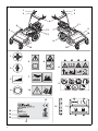 2
2
-
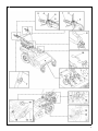 3
3
-
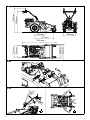 4
4
-
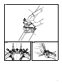 5
5
-
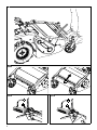 6
6
-
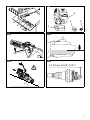 7
7
-
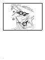 8
8
-
 9
9
-
 10
10
-
 11
11
-
 12
12
-
 13
13
-
 14
14
-
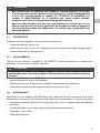 15
15
-
 16
16
-
 17
17
-
 18
18
-
 19
19
-
 20
20
-
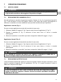 21
21
-
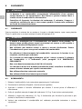 22
22
-
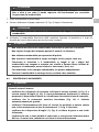 23
23
-
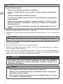 24
24
-
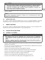 25
25
-
 26
26
-
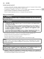 27
27
-
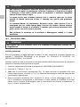 28
28
-
 29
29
-
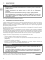 30
30
-
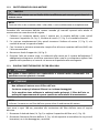 31
31
-
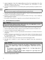 32
32
-
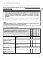 33
33
-
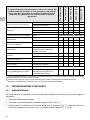 34
34
-
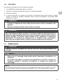 35
35
-
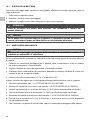 36
36
-
 37
37
-
 38
38
-
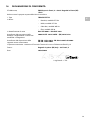 39
39
-
 40
40
-
 41
41
-
 42
42
-
 43
43
-
 44
44
-
 45
45
-
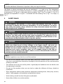 46
46
-
 47
47
-
 48
48
-
 49
49
-
 50
50
-
 51
51
-
 52
52
-
 53
53
-
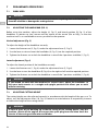 54
54
-
 55
55
-
 56
56
-
 57
57
-
 58
58
-
 59
59
-
 60
60
-
 61
61
-
 62
62
-
 63
63
-
 64
64
-
 65
65
-
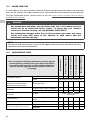 66
66
-
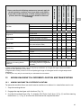 67
67
-
 68
68
-
 69
69
-
 70
70
-
 71
71
-
 72
72
-
 73
73
-
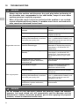 74
74
-
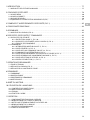 75
75
-
 76
76
-
 77
77
-
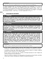 78
78
-
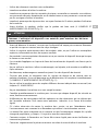 79
79
-
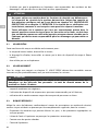 80
80
-
 81
81
-
 82
82
-
 83
83
-
 84
84
-
 85
85
-
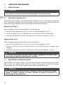 86
86
-
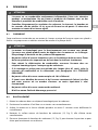 87
87
-
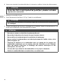 88
88
-
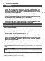 89
89
-
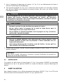 90
90
-
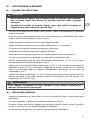 91
91
-
 92
92
-
 93
93
-
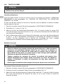 94
94
-
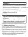 95
95
-
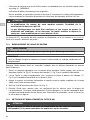 96
96
-
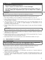 97
97
-
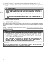 98
98
-
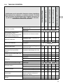 99
99
-
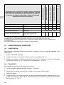 100
100
-
 101
101
-
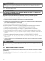 102
102
-
 103
103
-
 104
104
-
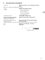 105
105
-
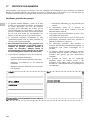 106
106
-
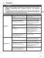 107
107
-
 108
108
-
 109
109
-
 110
110
-
 111
111
-
 112
112
-
 113
113
-
 114
114
-
 115
115
-
 116
116
-
 117
117
-
 118
118
-
 119
119
-
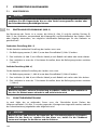 120
120
-
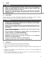 121
121
-
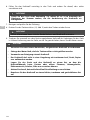 122
122
-
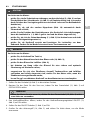 123
123
-
 124
124
-
 125
125
-
 126
126
-
 127
127
-
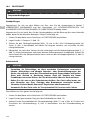 128
128
-
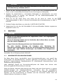 129
129
-
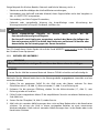 130
130
-
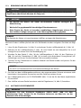 131
131
-
 132
132
-
 133
133
-
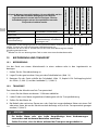 134
134
-
 135
135
-
 136
136
-
 137
137
-
 138
138
-
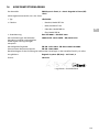 139
139
-
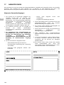 140
140
-
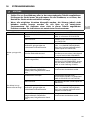 141
141
-
 142
142
-
 143
143
-
 144
144
-
 145
145
-
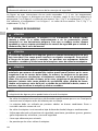 146
146
-
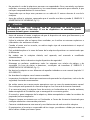 147
147
-
 148
148
-
 149
149
-
 150
150
-
 151
151
-
 152
152
-
 153
153
-
 154
154
-
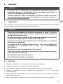 155
155
-
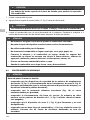 156
156
-
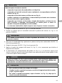 157
157
-
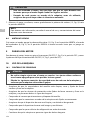 158
158
-
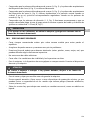 159
159
-
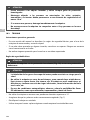 160
160
-
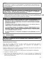 161
161
-
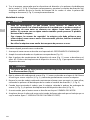 162
162
-
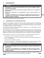 163
163
-
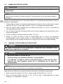 164
164
-
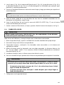 165
165
-
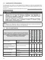 166
166
-
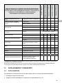 167
167
-
 168
168
-
 169
169
-
 170
170
-
 171
171
-
 172
172
-
 173
173
-
 174
174
-
 175
175
-
 176
176
-
 177
177
-
 178
178
-
 179
179
-
 180
180
-
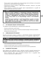 181
181
-
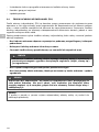 182
182
-
 183
183
-
 184
184
-
 185
185
-
 186
186
-
 187
187
-
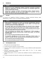 188
188
-
 189
189
-
 190
190
-
 191
191
-
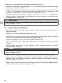 192
192
-
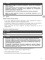 193
193
-
 194
194
-
 195
195
-
 196
196
-
 197
197
-
 198
198
-
 199
199
-
 200
200
-
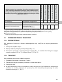 201
201
-
 202
202
-
 203
203
-
 204
204
-
 205
205
-
 206
206
-
 207
207
-
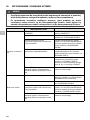 208
208
-
 209
209
-
 210
210


Efco DR 50 K800H El manual del propietario
- Categoría
- Herramientas de jardín
- Tipo
- El manual del propietario
en otros idiomas
- français: Efco DR 50 K800H Le manuel du propriétaire
- italiano: Efco DR 50 K800H Manuale del proprietario
- Deutsch: Efco DR 50 K800H Bedienungsanleitung
- polski: Efco DR 50 K800H Instrukcja obsługi
Artículos relacionados
Otros documentos
-
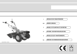 Bertolini 405 S El manual del propietario
-
Nibbi FC 150 MS El manual del propietario
-
Nibbi 407 S Limited Edition El manual del propietario
-
Nibbi NTS 65 El manual del propietario
-
Nibbi 417 S El manual del propietario
-
-
-
hillvert HT-MD-300B El manual del propietario
