
Cable locator
USER MANUAL

2
Cable locator
OPENING THE BOX
When you receive this cable locator, please inspect it carefully to ensure that
it has not been damaged in transit. Normally accessories, control switches
and connectors need to be checked. If there is obvious damage or functional
failure, please contact the supplier.
Main parts
1. Bag
2. Receiver: 1 pc.
3. Emitter: 1 pc.
4. Accessories:
5. Crocodiles (red and black respectively)
6. Battery: 1 pc.
(9V alkaline battery, GL6F22A 1604)
7. Battery: 6 pcs.
(1.5V alkaline battery, LR03 SIZE)
8. User manual: 1 pc.
9. Test leads: 2 pcs.
10.Test probe: 2 pcs.
(red and black respectively)
10.Earth spike
SAFETY INFORMATION
WARNING
This cable locator is produced in accordance with the safety specifications for
electronic meters and test instruments and has been tested prior to packaging
and transportation. Before using this product, please read this manual
carefully and follow the instructions. Failures resulting from not following these
instructions or ignoring the warnings and cautions can result in personal
injury, danger to life, or equipment damage.

3
Cable locator
Definition of safety symbols
This manual includes the basic elements for the safe operation and
maintenance of the cable locator. Before using this product, please read the
following safety instructions carefully.
Table 1: Safety instructions
Important information that users should read before using the
product.
Indicates that the terminal may be dangerous.
Conformity symbol.
Table 2: Warning instructions
Improper use can cause serious injury or death.
Improper use or carelessness can lead to personal injury, cable
locator damage, or error in measurement results.
Recommendations or tips for operation.
Attention!
Please follow the instructions below to ensure safe operation and optimal
performance.
1) Preliminary inspection
Before the first use, check if the cable locator works normally
and make sure that it has not been damaged during storage
and transportation. If there is any damage, contact the supplier.
When using the Cable Locator, you must follow the safety
specifications of the electronics industry.

4
Cable locator
2) Location
Temperature range for use 0-40º (32-104º), <80% RH (non-condensing)
Temperature range for storage -20ºC + 60ºC (-6º140ºCF), <80% RH (non-
condensing)
•To avoid failures or incidents please do not place the cable locator in the
following environments:
Direct exposure to
sunlight or high
temperatures
Dust High
electromagnetic
radiation
Water spray
High humidity
condensation
Corrosive gas or
explosive
Mechanical vibration

5
Cable locator
3) Use
The following instructions must be followed to avoid electric shock, short
circuit, or explosion:
•This cable locator can be used in live parts, but measures must be taken
according to industrial safety codes to avoid electric shock and damage.
•To avoid electric shocks, you must pay special attention to the VDE and
safety regulations in force regarding excessive contact voltages, when
working with voltages that exceed 120V (60V) DC or 50V (25V) rms AC.
Values in parentheses are valid for limited scopes (such as medicine and
agriculture).
•Never try to put both battery poles in contact, for example by connecting a
cable. Never throw the battery into a fire, or it could cause an explosion.
•When replacing or changing the battery, be sure to use the correct polarity.
Batteries with reversed polarity may destroy the instrument. They could also
explode or catch fire.
Attention!
•Measurements near electrical installations that may pose a hazard should
only be carried out under the supervision of the responsible electrician.
•When the product is used to test a live line, make sure that the test
connectors are disconnected from the object under test before connecting
or disconnecting the test lead from the emitter, and remember that people
around must be well protected.
•Never try to remove the battery posts! The battery contains very strong
chemical agents. Danger of corrosion! If the contents of the battery come
into contact with the eyes, rinse immediately with plenty of water and
consult a doctor.
•Since the connection of the emitter with the mains can generate current in
the circuit at milliamp level, in the case of alignment to the emitter ground,
only the neutral conductor can be connected. If the emitter connection is
made between phase and the protective conductor, the functional safety of
the production conductor must first be tested, in compliance with DIN VDE
0100. The reason is that when connecting the -Continues-

6
Cable locator
emitter from between phase and earth, all parts that are connected to earth
could be live generating a fault (if the earth resistance does not comply
with the prescriptions).
•If user protection is not ensured, the instrument must be taken out of service
and its use avoided. Safety is not guaranteed if the instrument:
- shows obvious damage
- does not carry out the desired measurements.
- has been stored for a long time under unfavorable conditions.
- has been subjected to mechanical action during transport.
•The instrument will only be used under these conditions and for the purpose
for which it was designed. When the instrument is modified or changed,
operational safety is not guaranteed.
Caution!
•The operating temperature of this cable locator is 0-40º C (32-140ºF)
•To avoid damage, this device must be protected from excessive mechanical
vibrations during transport or use, especially from drops.
•Only professionals are authorized to calibrate and repair this instrument.
•Before use, inspect the instrument and the test lead in use for external
damage. Please make sure the instrument and the test lead are intact. The
instrument must not be used unless all the functions of the apparatus are
well prepared for operation.
•When using the instrument, the nominal voltage of the circuit to be tested
must not exceed the voltage indicated in the technical specifications of this
cable locator.
•Keep the instrument away from sun exposure to ensure its perfect
performance and a long life.
•If the instrument is subjected to a high electromagnetic field, its functional
ability may be affected.
•Use only batteries as indicated in the technical data section.
•Try to keep the battery away from moisture. If the display shows a flashing
battery sign, the batteries should be changed.

7
Cable locator
Recommendations
•Before using a locator that has been located or transported under extreme
weather conditions, please place it in a favorable environment for a period
of time.
•When the emitter is connected to the network, if the emitter earth is
connected to the protective earth, the leakage current (if any) in the power
supply can add to the current of the emitter circuit, leading to dispersion to
the circuit breaker, eg FI / RCD trip.
•Please keep the original packaging for later shipments (eg for calibration of
the device).
1 DESCRIPTION
1.1 Product introduction
When drilling a hole in the wall to install an air conditioner or in the ground for
installing a machine, or when digging in a road, you need to know the routing
of the cables, water or gas pipes in the wall or the ground to avoid
unnecessary damage and even dangerous situations.
In the past there was only one solution to this situation, which was to find
the construction plans for these installed services. However, in the majority
of cases, these plans were not accessible and the risk of interruption of
cables or pipes had to be run, carrying the consequent danger or failure of
supply, electric shock, explosion, or danger of death.
Now with this cable locator developed by our company to effectively help
users locate or detect cables, you don't need to take any more risks.
This cable locator is a portable instrument consisting of a transmitter, a
receiver and various accessories. With advanced integrated parts and
digital technology circuits, it is characterized by its reliable and safe
electrical performance. The emitter sends AC voltage modulated by digital
signals to the target wire (or metal pipes), which generates an alternating
electric field; -Continues-

8
Cable locator
place the receiver sensor head close to this electric field and the sensor will
generate induced voltage. This instrument can magnify a weak voltage signal
hundreds of times and then display it on the monitor after decoding the audio
frequency, demodulating and performing digital processing, so that the
position of buried cables or pipes, as well as their faults, can be detected
based on signal change.
This cable locator is easy to use and provides comfortable operation by
means of buttons, which indicate a correct press by emitting buzzes. In
addition, the screen allows visualization and the transmitter and receiver are
equipped with LED lights.
The emitter not only emits signals but also acts as a voltmeter, in this way the
instrument can display the voltage of the tested line, including the AC / DC
differentiation, apart from showing a warning symbol when checking an active
line. The sender is also provided with a self-inspection function, which notifies
on the screen if the sender is transmitting signals, making the users more
confident in the checks.
The receiver display is backlit, so users can see test results even in the dark.
To improve the efficiency of the test, the receiver is equipped with a
loudspeaker, which will emit changing tones as the signal strength changes,
in this way users can judge the effects of the test simply by the sounds, to
your greatest comfort. To adapt the instrument to a noisy environment, the
speaker emits a loud sound. Of course, both the transmitter and the receiver
have a mute mode to avoid discomfort during use.
The cable locator is applied in construction involving telecommunication
cables, power cables and pipeline construction, as well as the maintenance
of such cables and pipes.

9
Cable locator
1.2 Features of the cable locator
• Detection of cables, power lines, water / gas supply pipes buried in the wall
or ground.
• Detection of interruptions and short-circuits in cables and electric lines buried
in the wall or the ground;
• Detection of fuses and assignment of current circuits;
• Trace of distribution sockets and plugs that have been accidentally covered
by plastering;
• Detection of interruptions and short circuits in underfloor heating;
• The emitter has a built-in AC / DC voltmeter function, which can measure 12
to 400 V AC / DC voltage on a linear basis:
• AC: 12 to 400V (50 to 60 Hz) ± 2.5%
• DC: 12 to 400V ± 2.5%
• The emitter display can show a preset transmit power, transmitted codes, its
own battery power, the detected mains voltage, the status of the detected
AC / DC voltage from the mains and the symbol warning for mains voltage.
• The emitter has the self-inspection function to detect its own working status
and display it on the LCD screen for user reference.
• The receiver's display can show the transmitter's transmit power, transmitted
codes, energy from its own batteries and those of the AC transmitter induced
in the detected signal, and a warning symbol for mains voltage.
• The receiver sensitivity can be adjusted manually or automatically.
• The receiver can perform frequency sweep automatically.
• Both transmitter and receiver can work in mute mode.
• The receiver is available in automatic power-off mode (it turns off
automatically after 10 minutes of pressing any button)
• The receiver's LCD screen is provided with a backlight for application in low
light.
• Both emitter and receiver are provided with flash light function to work in the
dark.
• Additional emitters are available to amplify or distinguish various signals.
• Compact, resistant and portable.

10
Cable locator
1.3 Names and functions of the parties.
1.3.1 Scheme of the issuer
1. LCD screen
2. On / off switch
3. Button to adjust / confirm power level transmission (Level I, II or III)
4. Button to transmit or stop the transmission of encoded information.
5. Button to adjust / confirm the encoded information to be transmitted. Press this
button for 1 second to enter the code and press it briefly to exit (Code F, E, H, D,
L, C, O or A can be selected, default would be F).
6. Down key. When setting the power level or code, press to scroll down.
7. Up key. When setting the power level or code, press to go up.

11
Cable locator
8. Key to enable or disable mute mode (there will be no key tone in this mode)
9. Key to turn on / off the flash light.
10.Terminal +, input / output of the emitter. The emitter is connected to external
cables with the test connectors through this terminal to send signals and receive the
detected voltage signals.
11. Ground yourself. The emitter is in contact with the earth through this terminal.
1.3.2 Emisor screen
1. Symbol to indicate the voltage / energy of the transmitter battery.
2. Transmit power level (level I, II or III)
3. Transmitted code (by default F)
4. AC mains voltage
5. DC voltage of the electrical network
6. Mains voltage value (can be used as an ordinary voltmeter; range: 12 to
400V DC / AC)
7. Transmission status.
8. Code being transmitted
9. Intensity of the signal being transmitted.
10. Symbol indicating the voltage in the network.
11. Symbol indicating the mute mode.

12
Cable locator
1.3.3 Receiver diagram
1. Flash.
2. Test head.
3. LCD screen.
4. On / off button.
5. Composite key for backlight and mute mode. Press lightly to enable /
disable mute mode (under mute mode, both key tone and speaker are muted).
6. Key to turn on / off the flash.

13
Cable locator
7. UAC key to switch between cable locator mode and mains voltage.
8. Manual key to switch between manual or automatic cable locator.
9. Key to adjust the sensitivity down in manual mode.
10. Key to adjust the sensitivity upwards in manual mode.
11. Speaker.
1.3.4 Receiver display
1. Symbol to indicate the voltage / power of the receiver battery.
2. Symbol to indicate the voltage / energy of the emitter battery.
3. Transmit power level (level I, II or III).
4. Manual mode symbol.
5. Automatic mode symbol.
6. In automatic mode, this number indicates the signal strength, in manual
mode it shows SEL to indicate no signal or shows a number that indicates
signal strength, in UAC mode, UAC is displayed .
7. Concentric circles indicate preset sensitivity in graphics. More circles
indicate higher sensitivity, fewer circles indicate lower sensitivity.
8. Code received
9. Intensity of the signals.
10. Symbol indicating the voltage in the network.
11. Symbol indicating the mute mode.

14
Cable locator
1.3.5 Receiver display in cable locator mode
(1) Automatic mode (2) Manual mode
(3) Mains voltage identification mode
2. METHOD OF MEASUREMENT
2.1 Measurement precautions
Attention!
1. Since the connection of the emitter with the network can generate current in
the circuit at milliamp level, under live conditions the earth connection of the
emitter can only be connected with a neutral conductor. If the connection of the
emitter is made with the phase towards the protective conductor, the functional
safety of the production conductor must be tested first, in compliance with DIN
VDE 0100. The reason is that when connecting the emitter from the phase
towards the earth all the parts that are connected to earth could generate an
error (if the earth resistance does not comply with the prescriptions).
2. When the emitter is connected to the active network, if the earth of the emitter
is connected with the protective phase of earth, the current leakage (if

15
Cable locator
exists) of the power supply may find the emitter current circuit, causing the
current switch to trip. E.g. FI / RCD trips
Recommendations
1. When using the emitter as a voltage tester to check the mains voltage, a
small spark will be produced when the probe touches the mains voltage,
this is normal.
2. If any of the on / off, code, and level keys are active, the other two are
disabled.
3. If the receiver is in automatic mode, it can switch to manual mode or
mains voltage identification mode at any time; If the receiver is in manual
mode, both the UAC key and the Manual key will be enabled when
exiting manual mode.
2.2 Principle of operation
The cable locator includes an emitter, a receiver and accessories. The
emitter sends to the target cable (or metallic pipes) an AC voltage modulated
by digital signals, which generates an alternating electric field (see Fig. 2-1);
place the tip of the receiver close to this field, and the sensor will generate
induced voltage. This instrument can amplify this weak signal hundreds of
times and display it on the LCD screen after digital processing, in this way the
position of buried cables or pipes, as well as their faults, can be detected
based on the change of the signal.
Caution!
1. For any application, the emitter connections must ensure a closed circuit.
2. This cable locator can only detect or locate correctly connected lines
according to the described physical principle.

16
Cable locator
Optional connections for this cable locator
1. Single pole application: Connect the emitter to one conductor only. Due to
the high frequency of the signal generated by the emitter, only a single
conductor can be located and traced. The second conductor is the ground.
This arrangement causes the high-frequency current to flow through the
conductor and be transmitted to the ground, similar to the operation of a
radio receiver.
2. Double pole application: The emitter is connected to the conductor by two
test leads. This application includes working and unused electrical networks.
The transmitter is connected to the working network:
Connect the “+” connector of the emitter to the line phase of the network and
the earth connection of the emitter to the neutral line of the network. In these
circumstances, if there is no load on the network, the modulated current from
the emitter will go to the neutral line via connection through the capacitance
distributed in the network and then return to the emitter.
The sender is connected to an unused network:
Connect the “+” connector of the emitter to a terminal of a line on the network,
connect the ground to the terminal of another parallel line on the network, and
then connect the other two terminals of the network to each other. In these
circumstances, the modulated current will return directly to the terminal
through the network. Optionally, the two test leads of the emitter can be

17
Cable locator
connected respectively to the two end ends of the conductor. In addition, the
“+” conductor of the emitter can be connected to the network terminal while
the earth terminal of the emitter can be connected to the earth protection
terminal of the network.
2.3 Typical application examples
In this example, please take a shielded length of cable with a cross section of
1.5mm. Temporarily install 5m of this cable along the wall with surface mount
clips. Make sure the wall is accessible from both sides. Create an artificial
interruption at a distance of 1.5m before one end of the line. The ends of the
line must be open. Select the interrupted wire at the beginning of the shielded
cable and connect it using the test leads (provided) with connector 10 of the
emitter. Connect the emitter connector 11 to a suitable ground. The remaining
wires must also be connected to the emitter and to the same ground (See
Fig.2.2).
Turn on the transmitter by pressing key 2 and the LCD screen of the
transmitter will show the initial screen and the instrument will emit a sound.
Press the 3 key on the transmitter to access the screen and adjust the
transmission level and then press the up key 7 or the down key 6 to select the
transmit power level (level I, II or III).
After this level is adjusted, press the 3 key to exit.
If you want to change the reporting code, please press the transmitter key 5
for 1 second and then press the up key 7 or the down key 6 to select the
reporting code (F, E, H, D, L, C, O or A, with defect F). Press the 5 key to
exit. Then press the 4 key to send the signal. At this time, the concentric
circles 7 will gradually expand on the LCD screen, and the symbol 8 will show
the transmission code received by the sender, and the symbol 9 will show the
signal strength. Press the 4 key on the receiver to turn on and the receiver's
LCD screen will show the initial screen, the instrument will beep, and the
receiver will default to “auto mode”.
Move the tip of the receiver slowly along the cable towards the interruption
position, the symbol 3 on the receiver will show the transmit power level, 8 will
show the code transmitted by the emitter, 9 will show the dynamic intensity

18
Cable locator
of the signal, and the speaker will change the pitch with the change in signal
strength.
When the tip of the receiver reaches the break position, the signal strength shown
by 9 and 6 will have an obvious drop until they finally disappear.
At this time, press the receiver's MANUAL key 8 to engage manual mode and
then use the 9 and 10 keys to reduce the sensitivity as much as possible while
ensuring that the receiver's display 8 can show the code transmitted by the
transmitter. This zone will be where the interruption is located.
SUGGESTIONS
1. Full contact with the earth must be assured.
2. Adjust the transmitter transmit power level to suit different detection radii.
The best way is to mark the break position on the other side of the wall.
Press the MANUAL key on the receiver to turn on manual mode. Press
keys 9 and 10 to reduce the sensitivity and ensure that the signal can be
received. Trace the signal in front of the wall with the receiver until it is no
longer indicated. The position of the interrupt can be located by this
setting.
3 APPLICATION DETAILS 3.1
Application of a pole

19
Cable locator
3.1.1 In open circuit
-Detect line interruptions in the wall or under the floor;
-Find and trace lines, sockets, junction boxes, switches, etc. in home
facilities;
-Find bottlenecks, bends, buckles and obstructions in installation pipes using
metal cables.
-Caution!
-When using this application, please make sure that the earth protection
cable is working properly.
Recommendations
1. Open circuit application is suitable for finding outlets and switches in
unused equipment.
2. The depth of scan depends on the medium and application. A typical
depth is between 0 and 2m. The protective terminal of an electrical outlet
can be used as the grounding connection for the emitter.
3.1.2 Location and tracking of lines and intakes
Preconditions:
•The circuit must be unused.
•The neutral line and the earth wire must be connected and fully
operational.
•Connect the emitter to the line and to earth, following Fig. 3-1-2.

20
Cable locator
Recommendations
1. Full contact with the ground must be assured.
2. With the indication of a pole, the lateral branches of the circuit can also
be located (the fuse must be removed in this example)
3. If the cable that feeds the signals via the transmitter is located, p. For
example, directly in parallel with other conductors (eg cable gap or
conduit), or if these conductors are crossed, the signals also serve as
input for the other conductors.
4. During locating and tracking, the larger the signal displayed, the closer
the locator will be to the lines being drawn.
5. Adjust the transmit power level of the emitter to suit the different
detection radii.
6. The position of the target can be precisely located by setting the manual
mode on the receiver and selecting a suitable sensitivity.
3.1.3 Location of line interruptions
Preconditions:
*The circuit must be unused
*All lines not required must be connected to auxiliary ground according to Fig.
3-1-3.
*Connect the terminal to a wire and auxiliary ground according to Fig. 3-1-3.

21
Cable locator
Caution!
1. Full contact with the ground must be assured.
2. The transition resistance of a line break must be greater than 100kOhm.
3. When tracing the line break in multi-conductor cables, pay attention that
all cables remaining in the insulated cable or conductor must be
grounded in accordance with regulations. This is required to avoid cross
coupling of the applied signals (by a capacitive effect of the source
terminals). The tracing depth for the shielded cables and connectors is
different, since the individual wires of the conductors in the shielded
cables are twisted together.
Recommendations
1. The ground connected to the emitter can be an auxiliary ground, an outlet
ground, or a pipe that is properly grounded.
2. During tracing along the line, the position where the signal received by the
receiver drops sharply is the location of the break.
3. Adjust the power level of the emitter to suit different detection radious.

22
Cable locator
4. The position of the target can be precisely located by setting the
manual mode on the receiver and selecting a suitable sensitivity.
3.1.4 Location of interruptions in the line using two emitters
When locating a interruption in the line using an emitter that feeds the end of a
conductor, the location of the interruptions may not be carried out accurately in
case bad conditions occur due to interference in the field.
The drawbacks described above can be easily avoided by using two emitters
(one at each end) for the detection of the interruption in the line.
In this example, a different line code is set for each transmitter, eg F code in
one and C code in the other. (The second issuer is not included and must be
purchased separately.)
Preconditions:
* The circuit current must not be active.
* All lines that are not being used must be connected to auxiliary ground as
shown in Fig. 3-1-4.
* Proceed as described in the sample application.
If the emitters are connected according to Fig. 3-1-4, the receiver will indicate
C on the left side of the line break. If the receiver goes beyond the position of
the break to the right, it will show F. If you are directly above the break, no
line of code is displayed, due to the overlap of both emitter signals.

23
Cable locator
Suggestions
1. Adjust the transmit power level to suit different detection radious.
2. The position of the target can be precisely located by setting the receiver's
manual mode and selecting the appropriate sensitivity.
Caution!
1. Contact with the ground must be assured.
2. The transition resistance of a line break must be greater than 100kOhm.
3. The ground connected to the emitter can be an auxiliary ground, ground
from a grounded outlet, or a pipe that is properly grounded.
4. When tracing the line break in multi-conductor cables, pay attention that all
cables remaining in the insulated cable or conductor must be grounded in
accordance with regulations. This is required to avoid cross coupling of the
applied signals (by a capacitive effect of the source terminals). The tracing
depth for the shielded cables and connectors is different, since the individual
wires of the conductors in the shielded cables are twisted together.

24
Cable locator
3.1.5 Error detection in underfloor heating.
Preconditions:
* The circuit current must not be active.
* All lines not being used must be connected to the auxiliary ground as shown
in Fig. 3-1-5a.
* Connect both emitters (if two emitters are used) as shown in Fig. 3-1-5b.
* Proceed as described in the sample application.
Precautions
1. If there is protective material on top of the heating cables, there must be no
ground connection. If required, separate the shield from the ground
connection.
2. Full contact with the ground must be ensured, and there must be a
considerable distance between the emitter ground and the target line. If this
distance is too short, the signal and the line cannot be located properly.
SUGGESTIONS
1. During tracing along the line, the position where the signal received by the
receiver drops sharply is the location of the break.
2. Adjust the emitter power level to suit different detection radii.
3. The position of the target can be precisely located by setting the receiver's
manual mode and selecting the appropriate sensitivity.

25
Cable locator
3.1.6 Detection of the narrow (blocked) part of an installed non-metallic
pipe
Preconditions:
* The pipe must be made of non-conductive materials (such as plastic).
* The pipe should not be loaded.
* The emitter is connected to a metal helical tube (metal tube or flexible
conductor) and an auxiliary ground, as shown in Fig. 3-1-6.
* The measurement method is the same as that used in the example.
1. If there is current in the pipeline, cut off the power, and connect the ground
correctly when the pipeline is not loaded.
2. The end of the ground must be perfectly anchored, and the end of the
ground of the emitter must be at a certain distance from the pipe to be
measured. If this distance is too short, the signal and the circuit cannot be
precisely located. If you only have a helical tube that is made of non-
conductive material (such as fiberglass), we suggest you insert a metal wire
with a section area of about 1.5mm2 into the non-metallic helical tube, and
then push it towards the part narrow.
Precautions
1. If you only have a helical tube that is made of non-conductive material (such as
fiberglass), we suggest that you insert a metal wire with a section area of about
1.5mm2 into the non-metallic helical tube, and then push it towards the narrow part.

26
Cable locator
2. In the pipeline detection process, the stronger the signal displayed on the
Nixie tube of the detector, the closer the pipeline will be detected by the
instrument.
3. In the detection process along the pipeline, if the signals received by the
receiver suddenly attenuate, the localized position is where the blocking takes
place.
4. Adjust the transmitting power of the emitter to suit different detection radii.
Select manual mode on the receiver and the appropriate sensitivity to
precisely locate the narrow part.
3.1.7 Detection of the metallic water pipe and the metallic heating pipe.
Preconditions:
* The pipe must be made of metallic material (such as galvanized steel).
* The pipe to be detected must not be on the ground. There should be a high
resistance between the pipe and the ground (otherwise the sensing distance will
be very short).
* Use a connecting cable to connect the grounding of the emitter to the ground,
and properly anchor the end of the ground.
* Use a connection cable to connect the “+” socket of the emitter to the pipe to
be detected.
The detection of the key of the metal pipe and the heating pipe. Preconditions
are shown in Fig. 3-1-7a and Fig. 3.1.7b respectively:

27
Cable locator
Precautions
For the sake of safety, the power supply of electrical equipment must be
turned off.
SUGGESTIONS
1. The ground end of the emitter must be some distance away from the pipe
to be detected. If the distance is too short, the signals and the circuit cannot
be precisely located.
2. In the pipeline detection process, the stronger the signals displayed on the
Nixie tube of the detector, the closer the pipe is to be detected.
3. Select the receiver's manual mode and an appropriate sensitivity to
precisely locate the pipe.
4. To detect a pipe made of non-conductive materials, we suggest inserting a
helical metal tube first into the pipe, as described in Section 3.1.6.
3.1.8 Detection of the supply circuit on the same floor
To detect the power circuit in the same plant please follow the following
steps:
1) Turn off the main switch of the distribution board of this plant,
2) Disconnect the neutral wire of the distribution board of this plant, from the
neutrals of other plants.
3) Connect the emitter as shown in Fig. 3-1-8.

28
Cable locator
WARNING
For safety, please cut off the supply to the entire building.
Suggestions
1. The emitter ground must be properly grounded and must be at a certain
distance from the pipe to be detected. If the distance is too small, the signals
and the circuit cannot be precisely located.
2. Adjust the transmitting power of the emitter to suit different detection radii.
3. In the process of detecting the circuit, the stronger the signal displayed on
the Nixie tube of the detector, the closer the circuit would be detected by the
instrument.
4. Select manual mode on the receiver and the appropriate receive sensitivity
to locate the circuit precisely.
3.1.9 Tracing a buried circuit.
Preconditions:
* The circuit must not be active.

29
Cable locator
* Connect the emitter as shown in Fig. 3-1-9.
* The grounding of the emitter must be properly grounded.
* Select the automatic mode of the receiver.
* Based on the displayed signal strength, find or trace the circuit.
Caution!
1. The distance between the earth wire and the circuit to be located should be
as wide as possible. If the distance is too small, the signals and the circuit
cannot be precisely located.
2. The depth of detection is highly influenced by ground conditions. Select the
appropriate receive sensitivity to precisely locate the circuit.
3. As you slowly move the receiver along the circuit to be located, you will see
that the display changes greatly. The strongest signals represent the precise
location of the circuit.
4. The greater the distance between the emitter and receiver signals, the
lower their power d, and the detection will be more superficial.
3.2 Double polarity applications.
3.2.1 Applications in closed circuits
It can be applied to circuits with current and circuits without current:
In circuits without current, the emitter only sends coded signals to the circuit

30
Cable locator
to detect.
In live circuits, the emitter only sends coded signals, but it also measures and
displays the voltage of the active circuit.
As shown in Fig. 3-2-1:
Caution!
When connecting active circuits to the emitter, please comply with the safety
instructions.
recommendations
1. The dielectric power of the emitter is 400v AC / DC.
2. The closed-circuit application is suitable for searching outlets, plugs and
fuses, etc., in electrical installations on floors with current or without current.
3. The detection depth is related to the measurement of the laid cable and the
way of use, the common detection depth is less than 0.5m
4. Adjust the transmitting power of the emitter to suit different detection radii.

31
Cable locator
3.2.2 Finding fuses
In a multi-dwelling building, use the L and N terminals of a household outlet to
send the emitter signals (as shown in Fig. 3-2-2) and set the transmit power of
the unit to a appropriate level.
Preconditions:
* Disconnect all air switches from the distribution box.
* Connect the emitter according to Fig. 3-2-2.
Caution!
1. Identification and positioning of fuses are highly influenced by the wiring
situation in the distribution panel. To search for fuses as precisely as possible,
you must open or remove the switch panel cover, and search for the fuse
feeder.
2. In the search process, the fuse with the strongest and most stable signals
will be the target to be searched for. Due to signal coupling, the detector can
detect signals from other fuses, but the strength of those signals will be
relatively weak.
Recommendations
1. For detection, it is better to put the detector tip at the inlet of the fuse box to
get the best detection result.
2. Adjust the transmitting power of the emitter to suit different detection radii.
Select manual mode on the receiver to set a suitable receive sensitivity to
precisely locate the circuit.

32
Cable locator
3.2.3 Search for a short circuit.
Preconditions:
* The circuit must be de-energized.
* Connect the emitter according to Fig. 3-2-3.
* The measurement method is the same as the example.
Caution!
1. If there is current in the cable, cut off the power first.
2. To search for short circuits of insulated wires and cables, the depth of
detection will vary depending on the cables that are twisted together in the
socket. In our experience, only short circuits with impedance less than 20
ohms can be detected correctly. The short circuit impedance can be
measured with a multimeter.
Recommendations
1. If the impedance of a short circuit is greater than 20 ohms, try using the
Find Circuit Break method to find the short circuit. To do this, use a relatively
high current to temporarily connect the fault part (low resistance) or interrupt
it.
2. In the detection process along the tube, if the signal received by the
receiver suddenly attenuates, the detected position is where the short circuit
is located.
3. Adjust the transmit power to suit different sensing radios.

33
Cable locator
4. Select the manual mode of the receiver and select a suitable receive
sensitivity to precisely locate the circuit.
3.2.4 Detect circuits installed with a certain depth.
In dual polarity applications, if the circuit is made up of multi-conductor cables
(such as NYM 3x1.5mm2), the depth of detection will be significantly limited.
The reason is that the short distance between the power line and the circuit
causes strong distortion in the magnetic field.
A magnetic field with sufficient power cannot be built with narrow parts. If a
separate circuit is used, this problem is easily solved, since the insulated
conductor can cause the magnetic field to diffuse with more power.
The circuit can be made up of any type of conductive cables or wires. The
important point is that the distance between the power line and the circuit is
not greater than the depth, and in practice this distance is normally 2m or
greater.
Preconditions:
* The circuit must be de-energized.
* Connect the emitter as shown in Fig. 3-2-4.
The distance between the power line and the circuit should be at least
2-2.5m.
* The measurement method is shown in the example.

34
Cable locator
Recommendations
1. In this application, the influence of moisture or mortar on the wall at the
depth of the location is significant.
2. During the circuit detection process, the stronger the signal displayed on
the detector's Nixie tube, the closer the detected wire will be.
3. Adjust the transmit power on the emitter to suit different detection radii.
4. Select manual mode on the receiver and adequate sensitivity on the
reception to locate the circuit precisely.
3.2.5 Classify or determine the installed circuit
Preconditions:
* The circuit must be de-energized.
* The ends of the core cables must be twisted and connected together.
* Connect the emitter as shown in Fig. 3-2-5.
* The measurement method is the same as shown in the example.

35
Cable locator
Caution!
1. If there is electrical current in the cable, cut off the power first.
2. The ends of the unshielded cables must lead together, and must be twisted.
3. If only one emitter is available, take multiple measurements by changing
the connection between the emitter and the cable.
Recommendations
1. When you change the connection between the emitter and the core wire,
different circuits can be distinguished if we change the transmission encoding.
2. Adjust the transmitting power of the emitter to suit different detection radii.
3. Acquire a transmitter with different transmission signals when necessary.

36
Cable locator
3.3 Method to increase the effective radius to detect circuits in load.
When the emitter is directly connected to the phase line and to the neutral wire
line the signals are conducted through two parallel circuits (as shown in Fig.
3-3-1), thus twisted circuits can sometimes emit signals that counteract each
other, leading to an effective radius of 0.5, at most. To eliminate this effect, the
connection should be as shown in Fig. 3-3-2, where the line uses separate
cables to increase the effective radius up to 2.5m, lines with greater distances
can be provided by the cable reel ( see Fig. 3-3-2).
WARNING
When connecting live circuits to the emitter, please observe the safety
instructions.
PRECAUTIONS
Pay attention to the distance between the emitter and the circuit to be
detected, to be able to clearly determine the circuit through the signals.
SUGGESTIONS
1. In the process of detecting the circuit, the stronger the signal indicated on
the digital tube of the detector, the closer the detected wire is.
2. Adjust the transmit power to accommodate different detection radii.
3. Select the manual mode of the receiver and an adequate sensitivity in the
reception to locate the circuit precisely.

37
Cable locator
3.4 Identify the network voltage and look for breaks in the circuit.
Preconditions:
* The circuit must be active and with AC voltage.
* Measurements should be made according to Fig. 3-4.
* Set the emitter to the "Mains voltage identification" mode (UAC mode).
Caution!
1. The AC signals detected by the emitter in UAC mode show whether the
circuit is live, and accurate measurement of voltage must be done through the
emitter's voltmeter function.
2. When searching for the ends of multiple lines, it is necessary to connect
each line separately.
Recommendations
1. This app does not need an emitter (Unless you want to use the emitter's
voltmeter function to accurately measure circuit voltage).
2. The columns that indicate the signal strength on the emitter screen and the
frequency of the signal tone are related to the power of the circuit to be
detected and the distance of the circuit. The higher the power and the shorter
the distance to the circuit, the more columns will be displayed and the higher
the frequency of the signal tone.
4 OTHER FUNCTIONS
4.1 Emitter voltmeter function
If the emitter is connected to a circuit under load and the external voltage is
greater than 12V, the lower left part of the emitter screen shows the current
voltage value, and the standard symbols are used to distinguish between
circuits. AC and DC (see 4, 5, 6 on the interface displayed on the emitter), and
an illuminated symbol with a triangular frame is displayed at the top of the
monitor (see 10 on the interface displayed on the emitter. The identification
scale it is 12-400V DC / AC (AC: 50-60Hz).
4.2 Work light function.
Press flash button 9 on the emitter or flash button 6 on the receiver to turn on
the work light, press the same buttons again to turn it off.

38
Cable locator
4.3 Backlight function
Press the backlight button 5 on the receiver to turn on the backlight, and
press it again to turn it off. The emitter has no backlight function.
4.4 Mute function
Press the mute button 8 on the transmitter to turn off the sound, this way it
will no longer emit any sound when pressing any button; press the mute
button again to turn off the transmitter's mute function, and the buzzer
function will return. Press the transmitter's backlight / mute button 5 for 1
second to turn off the sound, and the receiver's buzzer or speaker will not
make any sound; press and hold the backlight / mute button 5 on the receiver
for 1 second to deactivate the mute function, and the ringer and speaker
functions will be active again.
4.5 Auto power off function
The emitter does not have an automatic shutdown function. If any button on
the receiver is not pressed for a long period of time, the receiver will
automatically turn off after 10 minutes. Please press the on / off button 2 to
turn on the transmitter.
5 TECHNICAL PARAMETERS
5.1 Technical parameters of the issuer
1. Output signal -125 kHz
2. External voltage identification scale DC 12-400V + -2.5%; AC 12-400V
(50-60Hz) + x2.5%
3. LCD screen with display function and bar graph.
4. Dielectric strength against external voltage-400V AC / DC Max.
5. Overvoltage category: CAT III 300V
6. Pollution degree- 2
7. 1x 9V power supply, IEC 6lR61
8. Minimum power current-Around 31mA
9. Maximum power current-About 115mA
10. Fuse-F 0.5A 500B, 6.3x32mm
Temperature scale

39
Cable locator
11. During use- 0º to 40ºC, with a maximum relative humidity of 80% (without
condensation)
12. Storage -20º to 60º, with a maximum relative humidity of 80% (without
condensation)
13. Altitude - 2000m Max.
14. Dimensions (height x width x depth) 190mmx89mmx42.5mm
15. Weight:
- No battery-about 360g,
- With battery: about 420g
5.2 Technical parameters of the receiver
1. Scribing Depth - Scribing depth depends on material and specific applications.
Cable locate mode
2. Application of a pole- Around 0-2m.
3. Application two poles-Around 0-0.5m.
4. Single loop circuit - about 2.5m.
5. Identification of the voltage in the network-Over 0-0.4m.
6. LCD-screen with display and bar graph function.
7. Power supply - AAA 6x1.5V, IEC Lr03
Power consumption:
8. Minimum current-Around 32 mA.
9. Peak Current-Around 89mA.
Temperature scale
10. During use - 0º to 40ºC, with a maximum relative humidity of 80% (without
condensation).
11. Storage -20º to 60º, with a maximum relative humidity of 80% (without
condensation).
12. Altitude - 2000m max.
13. Dimensions (HxWxD) -241.5mmx78mmx38.5mm Weight:
- No battery- about 280g
- With battery-about 350g

40
Cable locator
6 REPAIR AND MAINTENANCE
1. If you suspect a faulty detector malfunction, please confirm that the battery
power is sufficient and the test lead is not broken.
2. Before returning the detector for repair, please disassemble the battery and
describe the malfunction, and then properly package the device to avoid
damage during shipping. Regarding the damages produced in the transport,
the company would assume the responsibility.
3. There is a fuse inside the emitter. If the fuse is damaged after the warranty
period, please replace it yourself with a fuse of the same model. This fuse is a
fast melt single wire type, so do not replace it with a helical wire type, or the
transmitting power and safety of the instrument will not be guaranteed.
6.1 Troubleshooting
If the detector does not work properly, please check the points in the attached
table:
Malfunction Puntos a comprobar Measures to be applied
I can't turn on the
appliance
Have you installed the
battery?
Is the battery power
too low?
Is the battery polarity
correct?
Install new batteries
Check polarity

41
Cable locator
Emitter cannot identify
external voltage
¿hay sonido de
contacto?
¿El conductor
está roto?
¿el conductor se ha
insertado del todo?
¿el cable de prueba
está roto?
¿se ha insertado el
cable de prueba del
todo?
Vuelva a conectar la
línea
Cambie el conductor
Inserte correctamente
el conductor
Cambie el cable de
prueba
Inserte correctamente
el cable de prueba
Power supply turns off
during measurement
Is the battery power
sufficient?
Does the instrument
turn itself off?
Change the battery
Switch the appliance
back on
The emisor cannot
receive the signal
¿Ha presionado el
botón de transmisión?
¿El fusible del emisor
está roto?
Have you pressed the
transmit button?
Is the emitter fuse
broken?
6.2 Checking the emitter fuse
Emitter fuse can prevent emitter damage from overload or malfunction. If
the emitter fuse has blown, the emitter can only emit weak signals. If the
self-test mode of the emitter is correct but the transmitted signal is weak, it
means that the transmission has been made but the fuse has blown. If no
signal is found during the transmission self-test state, and the battery
power is normal, it means that the emitter is broken and needs to be
repaired by specialized technicians.
Specific methods and steps to check the emitter fuse:
1. Cut off all measured emitter circuits.
2. Turn on the emitter and put it in the transmit state.
3. Set the transmitter's transmit power to level I.

42
Cable locator
4. Connect one end of the test lead to the 10 junction on the emitter.
5. Insert the other end of the test lead into the emitter connection socket.
6. Turn on the emitter to search for signals from the test lead, and move the
receiver probe toward the test lead.
7. If the fuse is not broken, the value displayed on the receiver is double.
6.3 Cleaning
Use a cloth dampened with clean water or neutral detergent to clean the
emitter, and then use a dry cloth to clean it again.
1. Before cleaning, please make sure that the equipment is turned off, and all
circuits are interrupted.
2. During the cleaning task, please do not use benzene, alcohol, acetone,
ether, ketone, thinner or gasoline, which may deform or discolor the
equipment.
3. After cleaning, use the equipment again when it is completely dry.
Changing the battery
If the battery symbol on the display flashes (1 from the sender or 1, 2 from the
receiver), and the buzzer sounds an alert, the battery must be changed. The
steps to replace the battery (emitter or receiver) are as follows:
1) Turn off the equipment and cut off the measurement circuits.
2) Unscrew the back of the equipment, and remove the battery cover
3) Remove the old battery
4) Install a new battery according to proper polarity
5) Put the battery cover on and tighten the screws.
WARNINGS
1. When inserting or replacing the battery, please pay attention to the correct
polarity of the battery. If the polarity of the battery is incorrect, the equipment
will be damaged. Also, it may cause explosion or fire.
2. Do not connect the two poles of the battery with a lead wire, and do not
throw the battery into fire, otherwise there may be a risk of explosion.

43
Cable locator
3. Please do not try to disassemble the battery! The electrolyte it contains
shows high basicity, which can cause corrosion! If the electrolyte comes into
contact with skin or clothing, use fresh water to clean the important parts. If
electrolyte gets into your eyes, use cool water to wash your eyes immediately,
and visit a doctor as soon as possible.
Caution!
1. Before changing the battery, the equipment must be switched off, all
connected measuring circuits must be interrupted, and all lead wires must be
removed.
2. Only the battery specified in the technical parameters can be used.
3. If the equipment is not going to be used for a long time, remove the battery.
If the detector is contaminated due to a battery leak, send the device to the
factory for cleaning and testing.
4. For the disposal of the used battery, please observe the existing regulations
for the recovery, reuse and disposal of batteries.
6.5 Calibration interval
To ensure the accuracy of the measurement made by the equipment, it must
be regularly calibrated by the company's adjustment personnel. The
recommended calibration frequency is annual. If the equipment is used
frequently or the conditions of use are very poor, the calibration interval will be
shorter. If the equipment is rarely used, the calibration frequency can be
extended to three years.


Localizador de cable
MANUAL DE USUARIO

2
Localizador de cable
APERTURA DE LA CAJA
Cuando reciba este localizador de cable, por favor examínelo cuidadosamente
para asegurar que no ha sufrido ningún daño durante el transporte. Normalmen-
te los accesorios, interruptores de control y conectores necesitan ser comproba-
dos. Si existe daño obvio o fallo funcional, por favor contacte con el proveedor.
Partes principales
1. Bolsa
2. Receptor: 1 ud.
3. Emisor: 1 ud.
Accesorios:
4. Cocodrilos (rojo y negro respectivamente)
5. Batería: 1 ud.
(Batería alcalina 9V, GL6F22A 1604)
6. Batería: 6 ud.
(Batería alcalina 1.5V, LR03 SIZE)
7. Manual de usuario: 1 ud.
8. Cables de prueba: 2 uds.
9. Sonda de prueba: 2 uds.
(rojo y negro respectivamente)
10. Pica de tierra
INFORMACIÓN DE SEGURIDAD
ADVERTENCIA
Este localizador de cable está producido de acuerdo a las especicaciones
de seguridad para medidores electrónicos e instrumentos de prueba y ha sido
probado antes de su embalaje y transporte. Antes de utilizar este producto, por
favor lea este manual cuidadosamente y siga las instrucciones. Fallos deriva-
dos por no seguir estas instrucciones o ignorar las advertencias y precauciones
pueden ocasionar lesiones personales, peligro de vida o daños en el equipo.

3
Localizador de cable
Denición de los símbolos de seguridad
Este manual incluye los elementos básicos para el funcionamiento seguros
y mantenimiento del localizador de cable. Antes de utilizar este producto, por
favor lee las siguientes instrucciones de seguridad cuidadosamente.
Tabla 1: Instrucciones de seguridad
Información importante que los usuarios deben leer antes de uti-
lizar el producto.
Indica que el terminal puede ser peligroso
Símbolo de conformidad
Tabla 2: Instrucciones de advertencia
La utilización incorrecta puede causar daños serios o la muerte
La utilización inadecuada o descuido puede llevar a lesiones per-
sonales, daño del localizador de cable o error en los resultados
de las mediciones
Recomendaciones o consejos para el funcionamiento
¡Atención!
Por favor siga las siguientes instrucciones para asegurar un funcionamiento
seguro y un rendimiento óptimo.
1) Inspección preliminar
Antes del primer uso, compruebe si el localizador de cable funciona con nor-
malidad y asegúrese de que no ha sido dañado durante el almacenamiento y
transporte. Si existe algún desperfecto, contacte con el proveedor.
Al utilizar el Localizador de cable, deberá seguir las especicacio-
nes de seguridad de la industria electrónica.

4
Localizador de cable
2) Ubicación
Rango de temperatura para el uso 0-40º (32-104º),<80% RH (sin condensación)
Rango de temperatura para almacenamiento -20ºC+60ºC(-6º140ºCF),
<80%RH (sin condensación)
• Para evitar fallos o incidentes por favor no coloque el localizador de cable en
los siguientes entornos:
Exposición directa a la
luz solar o altas tem-
peraturas
Polvo Alta radiación
electromagnética
Agua pulverizada
Alta humedad
de condensación
Gas corrosivo o
explosivo
Vibración mecánica

5
Localizador de cable
3) Uso
Las siguientes instrucciones deben seguirse para evitar una descarga elécti-
ca, corto-circuito o explosión:
• Este localizador de cable puede ser utilizado en partes activas, pero se de-
berán tomar medidas de acuerdo a los códigos de seguridad industrial para
evitar descargas eléctricas y daños.
• Para evitar descargas eléctricas, deberá prestar especial atención a las re-
gulaciones VDE y de seguridad en vigor en referencia a las tensiones de
contacto excesivas, al trabajar con voltajes que excedan los 120V (60V) DC
o 50V (25V) rms AC. Los valores entre paréntesis son válidos para alcances
limitados (como medicina y agricultura).
• Nunca intente poner en contacto ambos polos de la batería, por ejemplo, conec-
tando un cable. Nunca lance la batería al fuego, o podría ocasionar una explosión.
• Cuando reemplace o cambie la batería, asegúrese de utilizar la polaridad
correcta. Las baterías con la polaridad cambiada pueden ocasionar la des-
trucción del instrumento. Además podrían explotar o prender fuego.
¡Atención!
• Las mediciones cerca de instalaciones eléctricas que puedan suponer un pe-
ligro se realizarán solamente bajo la supervisión del electricista responsable.
• Cuando el producto se utilice para probar una línea activa, asegúrese de
que los conectores de prueba estén desconectados del objeto testado antes
de conectar o desconectar el conductor de prueba del emisor, y recuerde
que las personas de alrededor deben estar bien protegidas.
• ¡Nunca intente desmontar las pilar de la batería! La batería contiene agen-
tes químicos muy fuertes.¡ Peligro de corrosión! Si el contenido de la batería
entra en contacto con los ojos, enjuague inmediatamente con abundante
agua y consulte a un médico.
• Puesto que la conexión del emisor con la red puede generar corriente en
el circuito a nivel de miliamperios, en el caso de alineación a la toma de
tierra del emisor solamente se podrá conectar el conductor de neutro. Si la
conexión del emisor se realiza entre fase y el conductor de protección, la
seguridad funcional del conductor de producción deberá ser probada pri-
mero, en cumplimiento con DIN VDE 0100. La razón es que al conectar el

6
Localizador de cable
emisor desde entre fase y tierra, todas las partes que estén conectadas a
tierra podrían estar en tensión generando un fallo (si la resistencia de tierra
no cumple con las prescripciones).
• Si no se asegura la protección del usuario, el instrumento debe ser puesto fuera
de servicio y evitar su uso. La seguridad no se garantiza si el instrumento:
- muestra daño obvio
- no lleva a cabo las mediciones deseadas.
- ha estado almacenado durante largo tiempo en condiciones no favorables.
- se ha sometido a acción mecánica durante el transporte.
• El instrumento solo se utilizará bajo estas condiciones y con el propósito
para el que fue concebido. Cuando se modique o cambie el instrumento, la
seguridad operativa no está garantizada.
¡Precaución!
• La temperatura de funcionamiento de este localizador de cable es 0-40º C
(32-140ºF)
• Para evitar daños, este dispositivo debe estar protegido de vibraciones me-
cánicas excesivas durante su transporte o uso, especialmente de caídas.
• Solo los profesionales están autorizados a calibrar y reparar este instrumento.
• Previo al uso, inspeccione el instrumento y el cable de prueba en uso en
busca de daño externo. Por favor asegúrese que el instrumento y el cable de
prueba están intactos. El instrumento no debe ser utilizado a menos que to-
das las funciones del aparato estén bien preparadas para el funcionamiento.
• Cuando utilice el instrumento, la tensión nominal del circuito que va a ser
probado no debe exceder la tensión indicada en las especicaciones técni-
cas de este localizador de cable.
• Mantenga el instrumento alejado de la exposición solar para asegurar su
perfecto funcionamiento y una vida larga.
• Si el instrumento es sometido a un elevado campo electromagnético, su
habilidad funcional puede verse afectada.
• Utilice solamente baterías como las indicadas en la sección de datos técnicos.
• Intente mantener la batería alejada de la humedad. Si la pantalla muestra un
signo de batería parpadeante, las baterías deben ser cambiadas.

7
Localizador de cable
Recomendaciones
• Antes de utilizar un localizador que ha sido ubicado o transportado bajo
condiciones climáticas extremas, por favor sitúelo en un entorno favorable
durante cierto período de tiempo.
• Cuando el emisor esté conectado a la red, si la toma de tierra del emisor está
conectada la tierra de protección, la corriente de fuga (si existe) en la fuente de
alimentación puede añadirse a la corriente del circuito del emisor, llegando a
dispersar al interruptor diferencial del circuito, p.ej. disparo del FI/ RCD.
• Por favor, conserve el embalaje original para posteriores envíos (por ejem-
plo para calibración del aparato).
1 DESCRIPCIÓN
1.1 Introducción al producto
Al realizar un oricio en la pared para instalar un aire acondicionado o en el
suelo para la instalación de una máquina, o al excavar en una carretera, ne-
cesita conocer el trazado de los cables, las tuberías de agua o gas en la pared
o el suelo para evitar daños innecesarios e incluso situaciones peligrosas.
En el pasado solo existía una solución a esta situación, que era, encontrar los
planos de construcción de estos servicios instalados. Sin embargo, en la ma-
yoría de casos, estos planos no eran accesibles y se tenía que correr el riesgo
de la interrupción de cables o tuberías, comportando el consecuente peligro o
fallo de suministro, descarga eléctrica, explosión, o peligro de muerte.
Ahora, con este localizador de cable desarrollado por nuestra compañía para
ayudar de forma efectiva a los usuarios a localizar o detectar cables, no nece-
sitará correr más riesgos.
Este localizador de cable es un instrumento portátil que consiste en un emi-
sor, un receptor y diversos accesorios. Con partes integradas avanzadas y
circuitos de tecnología digital, se caracteriza por su rendimiento eléctrico a-
ble y seguro. El emisor envía al cable objetivo (o tuberías de metal) tensión
AC modulado por señales digitales, que genera un campo eléctrico alterno;

8
Localizador de cable
sitúe el cabezal del sensor del receptor cerca de este campo eléctrico y el
sensor generará tensión inducida. Este instrumento puede ampliar una señal
de tensión débil cientos de veces y después mostrarla en el monitor después
de decodicar la frecuencia audio, desmodular y realizar el procesado digital,
para que la posición de los cables o tuberías enterrados, así como sus fallos,
puedan ser detectados basándose en el cambio de señal.
Este localizador de cable es fácil de utilizar y proporciona un manejo cómodo
por medio de botones, que indican una pulsación correcta mediante la emisión
de zumbidos. Además, la pantalla permite la visualización y el emisor y recep-
tor están equipados con luces LED.
El emisor no solo emite señales sino que también actúa de voltímetro, de
esta manera el instrumento puede mostrar la tensión de de la línea compro-
bada, incluyendo la diferenciación AC/DC aparte de mostrar un símbolo de
advertencia cuando se comprueba una línea activa. El emisor también está
provisto de una función de auto-inspección, que notica en la pantalla si el
emisor está transmitiendo señales, haciendo que los usuarios confíen más en
las comprobaciones.
La pantalla del receptor posee retroiluminación, para que los usuarios puedan
ver los resultados de las comprobaciones incluso en la oscuridad. Para mejo-
rar la eciencia de la comprobación, el receptor está equipado con un altavoz,
que emitirá tonos cambiantes al tiempo que cambie la intensidad de la señal,
de esta manera los usuarios pueden juzgar los efectos de la comprobación
simplemente por los sonidos, para su mayor comodidad. Para adaptar el ins-
trumento a un entorno ruidoso, el altavoz emite un sonido alto. Por supuesto,
tanto emisor como receptor poseen un modo mute para evitar molestias du-
rante su uso.
El localizador de cable se aplica en construcción que implique cables de tele-
comunicaciones, cables de alimentación y construcción de tuberías, así como
el mantenimiento de dichos cables y tuberías.

9
Localizador de cable
1.2 Características del localizador de cable
• Detección de cables, líneas eléctrica, tuberías de suministro de agua/gas
enterradas en la pared o el suelo.
• Detección de interrupciones y corto-circuitos en cables y líneas eléctricas
enterradas en la pared o el suelo;
• Detección de fusibles y asignación de circuitos de corriente;
• Rastreo de tomas y enchufes de distribución que han sido accidentalmente
cubiertos mediante enlucido;
• Detección de interrupciones y corto circuitos en suelo radiante;
• El emisor tiene la función voltímetro AC/DC integrada, que puede medir de
12 a 400 V de tensión AC/DC en una base lineal:
• AC : 12 a 400V (50 a 60 Hz) ±2.5%
• DC : 12 a 400V ±2.5%
• La pantalla del emisor puede mostrar una potencia de transmisión preesta-
blecida, códigos transmitidos, su propia energía de batería, la tensión de-
tectada de la red eléctrica, el estado de la tensión AC/DC detectada de la
red eléctrica y el símbolo de advertencia para la tensión de la red eléctrica.
• El emisor tiene la función de auto-inspección para detectar su propio estado
de funcionamiento y mostrarlo en la pantalla LCD para referencia del usuario.
• La pantalla del receptor puede mostrar la potencia de transmisión del emisor,
códigos transmitidos, energía de sus propias baterías y las del tranmisor AC indu-
cida en la señal detectada y símbolo de advertencia de tensión de la red eléctrica.
• La sensibilidad del receptor puede ser ajustada manual o automáticamente.
• El receptor puede realizar un barrido de frecuencia automáticamente.
• Ambos emisor y receptor pueden funcionar en modo mute.
• El receptor está disponible en modo de apagado automático ( se apaga
automáticamente después de 10 minutos pulsar ningún botón)
• La pantalla LCD del receptor está provista de retroiluminación para su apli-
cación en caso de poca luz.
• Ambos emisor y receptor están provistos con función de luz ash para tra-
bajar en la oscuridad.
• Están disponibles emisores adicionales para ampliar o distinguir varias señales.
• Compacto, resistente y portátil.

10
Localizador de cable
1.3 Nombres y funciones de las partes.
1.3.1 Esquema del emisor
1. Pantalla LCD
2. Interruptor on/off
3. Botón para ajustar/ conrmar la transmisión del nivel de potencia (Nivel I, II o III)
4. Botón para transmitir o parar la transmisión de información codicada.
5. Botón para ajustar/ conrmar la información codicada a ser transmitida.
Pulse este botón durante 1 segundo para introducir el código y presiónelo
brevemente para salir ( Código F,E,H,D,L, C, O o A pueden seleccionarse
por defecto sería F).
6. Tecla abajo. Al establece el nivel de potencia o código, pulse para ir hacia abajo.
7. Tecla arriba. Al establece el nivel de potencia o código, pulse para ir hacia arriba.

11
Localizador de cable
8. Tecla para habilitar o deshabilitar el modo mute (no habrá tono de las teclas
en este modo)
9. Tecla para encender/apagar la luz ash.
10. Terminal +, entrada / salida del emisor. El emisor se conecta a cables
externos con los conectores de prueba a través de este terminal para enviar
señales y recibir las señales de tensión detectadas.
11. Toma tierra. El emisor está en contacto con la tierra a través de este terminal.
1.3.2 Pantalla del emisor
1. Símbolo para indicar la tensión/energía de la batería del emisor.
2. Nivel de potencia de transmisión (nivel I, II o III)
3. Código transmitido (por defecto F)
4. Tensión AC de la red eléctrica
5. Tensión DC de la red eléctrica
6. Valor de tensión de la red (se puede utilizar como un voltímetro ordinario;
rango: de 12 a 400V DC/AC)
7. Estado de transmisión.
8. Código que está siendo transmitido
9. Intensidad de la señal que está siendo transmitida.
10. Símbolo que indica la tensión en la red.
11. Símbolo que indica el modo mute

12
Localizador de cable
1.3.3 Esquema del receptor
1. Flash
2. Cabezal de prueba
3.Pantalla LCD
4. Botón encendido/apagado
5.Tecla compuesta para retroiluminación y modo mute. Presione ligeramente
para habilitar/deshabilitar el modo mute (bajo el modo mute, tanto el tono de
las teclas como el altavoz están silenciados)
6. Tecla para encender/apagar el ash.

13
Localizador de cable
7.Tecla UAC para cambiar entre modo localizador de cable y tensión de la red.
8. Tecla manual para cambiar entre localizador de cable manual o automático.
9.Tecla para ajustar la sensibilidad a la baja en modo manual.
10. Tecla para ajustar la sensibilidad al alza en modo manual.
11. Altavoz
1.3.4 Pantalla del receptor
1. Símbolo para indicar la tensión/energía de la batería del receptor.
2. Símbolo para indicar la tensión/energía de la batería del emisor.
3. Nivel de potencia de transmisión (nivel I, II o III)
4. Símbolo de modo manual
5.Símbolo de modo automático
6. En el modo automático, este número indica la intensidad de la señal, en el
modo manual muestra SEL para indicar que no hay señal o muestra un nú-
mero que indica la intensidad de la señal, en el modo UAC, se muestra UAC.
7.Círculos concéntricos indican la sensibilidad preestablecida en grácos. Más
círculos indican mayor sensibilidad, menos círculos indican menor sensibilidad.
8.Código recibido
9.Intensidad de las señales
10.Símbolo que indica la tensión en la red.
11. Símbolo que indica el modo mute.

14
Localizador de cable
1.3.5 Pantalla del receptor en el modo localizador de cable
(1) Modo automático (2) Modo manual
(3) Modo identicación de la tensión de la red
2. MÉTODO DE MEDICIÓN
2.1 Precauciones en la medición
¡Atención!
1. Puesto que la conexión del emisor con la red puede generar corriente en el
circuito a nivel de miliamperios, en condiciones con corriente la toma de tierra
del emisor solamente se podrá conectar con un conductor neutro. Si la cone-
xión del emisor se realiza con la fase hacia el conductor de protección, la se-
guridad funcional del conductor de producción deberá ser probada primero, en
cumplimiento con DIN VDE 0100. La razón es que al conectar el emisor desde
la fase hacia la tierra todas las partes que estén conectadas a tierra podrían
generar error (si la resistencia de tierra no cumple con las prescripciones).
2. Cuando el emisor esté conectado con la red activa, si la toma de tierra del
emisor está conectada con la fase protectora de tierra, la fuga de corriente (si

15
Localizador de cable
existe) de la fuente de alimentación puede encontrar el circuito de corriente del
emisor, provocando que se dispare el interruptor de corriente. P.ej. se dispara
el FI/RCD
Recomendaciones
1. Cuando utilice el emisor como un comprobador de tensión para compro-
bar la tensión de la red, se producirá una pequeña chispa en el momento
que la sonda toque la tensión de la red, esto es normal.
2. Si cualquiera de las teclas encendido/apagado, código, y nivel está acti-
va, las otras dos están inhabilitadas.
3. Si el receptor está en modo automático, puede pasar a modo manual o al
modo de identicación de la tensión de la red en cualquier momento; si el
receptor está en modo manual, tanto la tecla UAC como la tecla Manual
estarán habilitadas al salir del modo manual.
2.2 Principio de funcionamiento
El localizador de cable incluye un emisor, un receptor y accesorios. El emisor
envía al cable objetivo (o tuberías metálicas) una tensión AC modulada por
señales digitales, que genera un campo eléctrico alterno (ver Fig. 2-1); colo-
que la punta del receptor cerca de este campo, y el sensor generará tensión
inducida. Este instrumento puede amplicar esta señal débil cientos de veces
y visualizarla en la pantalla LCD después del procesado digital, de esta mane-
ra la posición de los cables o tuberías enterrados, así como sus fallos, pueden
ser detectados basándose en el cambio de la señal.
¡Precaución!
1. Para cualquier aplicación, las conexiones del emisor deben asegurar un
circuito cerrado.
2. Este localizador de cable solo puede detectar o localizar líneas correcta-
mente conectadas conforme al principio físico descrito.

16
Localizador de cable
Conexiones opcionales de este localizador de cable
1. Aplicación de un polo: Conecte el emisor solo a un conductor. Debido a la
alta frecuencia de la señal generada por el emisor, solo un conductor único
puede ser localizado y rastreado. El segundo conductor es el suelo. Esta
disposición causa que la corriente de alta frecuencia uya a través del con-
ductor y sea transmitida al suelo, similar al funcionamiento de un receptor
de radio.
2. Aplicación de doble polo: El emisor está conectado al conductor por dos
cables de prueba. Esta aplicación incluye redes eléctricas en funcionamiento
y sin uso.
El emisor está conectado a la red en funcionamiento:
Conecte el conector “+” del emisor a la fase de línea de la red y la toma de
tierra del emisor a la línea neutro de la red. En estas circunstancias, si no
existe carga en la red, la corriente modulada del emisor irá a la línea neutro vía
conexión a través de la capacitancia distribuída en la red y después volverá
al emisor.
El emisor está conectado a una red sin uso:
Conecte el conector “+” del emisor a un terminal de una línea en la red, conec-
te la toma tierra al terminal de otra línea paralela en la red, y después conecte
los otros dos terminales de la red entre sí. En estas circunstancias, la corriente
modulada volverá directamente al terminal a través de la red. Opcionalmente,

17
Localizador de cable
los dos cables de prueba del emisor pueden conectarse respectivamente a
los dos extremos nales del conductor. Además, el conductor “+” del emisor
puede conectarse al terminal de la red mientras que la toma tierra del emisor
puede conectarse al terminal de protección de tierra de la red.
2.3 Ejemplos típicos de aplicación
En este ejemplo, por favor tome un tramo de cable protegido con una sección
transversal de 1.5mm. Instale provisionalmente 5m de este cable a lo largo de la
pared con clips en montaje supercial. Asegúrese de que la pared es accesible
desde ambos lados. Cree una interrupción articial a una distancia de 1.5m antes
de un extremo de la línea. Los extremos de la línea deben estar abiertos. Selec-
ciona el hilo interrumpido al principio del cable protegido y conéctelo mediante
los cables de prueba (proporcionados) con el conector 10 del emisor. Conecte
el conector 11 del emisor a una tierra adecuada. Los restantes hilos deben estar
conectados también al emisor y a la misma tierra (Ver Fig.2.2).
Encienda el emisor pulsando la tecla 2 y la pantalla LCD del emisor mostrará la
pantalla inicial y el instrumento emitará un sonido.
Presione la tecla 3 del emisor para acceder a la pantalla y ajustar el nivel de trans-
misión y después presione la tecla arriba 7 o la tecla abajo 6 para seleccionar el
nivel de potencia de transmisión (nivel I, II o III).
Después de que este nivel esté ajustado, presione la tecla 3 para salir.
Si desea cambiar el código de transmisión, por favor presione la tecla 5 del emisor
durante 1 segundo y después presione la tecla arriba 7 o la tecla abajo 6 para
seleccionar el código de transmisión (F,E,H,D,L,C,O o A, con defecto F).
Presione la tecla 5 para salir. Después presione la tecla 4 para enviar la señal.
En este momento, los círculos concéntricos 7 se expandirán gradualmente en
la pantalla LCD, y el símbolo 8 mostrará el código de transmisión recibido por el
emisor, y el símbolo 9 mostrará la intensidad de la señal. Presione la tecla 4 del
receptor para encender y la pantalla LCD del receptor mostrará la pantalla inicial,
el instrumento emitirá un sonido, y el receptor entrará por defecto en “modo au-
tomático”.
Mueva la punta del receptor lentamente a lo largo del cable hacia la posición de
la interrupción, el símbolo 3 del receptor mostrará el nivel de potencia de trans-
misión, 8 mostrará el código transmitido por el emisor, 9 mostrará la intensidad

18
Localizador de cable
dinámica de la señal, y el altavoz cambiará el tono con el cambio de intensidad
de la señal.
Cuando la punta del receptor llegue a la posición de la interrupción, la intensidad
de la señal mostrada por 9 y 6 tendrán una caída obvia hasta que nalmente
desaparezcan.
En este momento, presione la tecla MANUAL 8 del receptor para conectar el modo
manual y utilice entonces las teclas 9 y 10 para reducir la sensibilidad tanto como
sea posible mientras asegura que la pantalla del receptor 8 puede mostrar el
código transmitido por el emisor. Esta zona será donde se localiza la interrupción.
SUGERENCIAS
1. El contacto completo con la tierra debe estar asegurado.
2. Ajuste el nivel de potencia de transmisión del emisor para adaptarlo a
diferentes radios de detección. La mejor manera es marcar la posición
de interrupción en el otro lado de la pared. Presione la tecla MANUAL del
receptor para encender el modo manual. Presione las teclas 9 y 10 para
reducir la sensibilidad y asegurar que la señal se puede recibir. Rastree
la señal en frente de la pared con el receptor hasta que ya no se indique.
La posición de la interrupción puede ser localizada mediante este ajuste.
3 DETALLES DE LA APLICACIÓN
3.1 Aplicación de un polo

19
Localizador de cable
3.1.1 En circuito abierto
- Detectar interrupciones de líneas en pared o bajo el suelo;
-Encontrar y rastrear líneas, tomas, cajas de conexiones, interruptores, etc. en
instalaciones del hogar;
-Encontrar cuellos de botella, curvaturas, pandeos y obstrucciones en tuberías
de instalación mediante cables metálicos.
¡Precaución!
Al utilizar esta aplicación, por favor asegúrese del buen funcionamiento del
cable de protección de tierra.
Recomendaciones
1. La aplicación en circuitos abiertos es adecuada para encontrar enchufes
e interruptores en equipos sin uso.
2. La profundidad de rastreo depende del medio y aplicación. Una profundi-
dad típica es entre 0 y 2m. El terminal de protección de una toma de co-
rriente eléctrica puede ser utilizado como la conexión a tierra del emisor.
3.1.2 Localización y rastreo de líneas y tomas
Condiciones previas:
• El circuito debe estar sin uso.
• La línea de neutro y el cable de toma tierra deben estar conectados y com-
pletamente operativos.
• Conecte el emisor a la línea y a la toma tierra siguiendo la Fig. 3-1-2.

20
Localizador de cable
Recomendaciones
1. El contacto total con el suelo debe estar asegurado.
2. Con la indicación de un polo, también pueden ser localizadas las deriva-
ciones laterales del circuito (el fusible debe ser retirado en este ejemplo)
3. Si se localiza el cable que se alimenta de las señales vía el emisor, p.
ej, directamente en paralelo a otros conductores (p.ej. hueco del cable o
conducto), o si estos conductores están cruzados, las señales también
sirven de entrada para los otros conductores.
4. Durante la localización y rastreo, cuanto mayor sea la señal mostrada,
más cerca estará el localizador de las líneas que están siendo trazadas.
5. Ajuste el nivel de potencia de transmisión del emisor para adaptarlo a los
diferenctes radios de detección.
6. La posición del objetivo puede ser localizada de manera precisa ajus-
tando el modo manual en el receptor y seleccionando una sensibilidad
adecuada.
3.1.3 Localización de las interrupciones de la línea
Condiciones previas:
* El circuito debe estar sin uso
*Todas las líneas no requeridas deben estar conectadas a la tierra auxiliar de
acuerdo con la Fig.3-1-3.
*Conecte el terminal a un hilo y a una tierra auxiliar de acuerdo con la Fig. 3-1-3.

21
Localizador de cable
¡Precaución!
1. El contacto total con el suelo debe estar asegurado.
2. La resistencia de transición de una rotura de línea debe ser superior a
100kOhm.
3. Al rastrear la rotura en la línea en cables de multiconductores, preste
atención a que todos los cables que permanezcan en el cable con aisla-
miento o conductor deben estar conectados a tierra de acuerdo con las
regulaciones. Esto se requiere para evitar acoplamiento cruzado de las
señales aplicadas (por un efecto capacitivo de los terminales de origen).
La profundidad de trazado para los cables protegidos y conectores es
diferente, ya que los cables individuales de los conductores en los cables
protegidos están trenzados entre ellos.
Recomendaciones
1. La tierra conectada al emisor puede ser una tierra auxiliar, una tierra de
una toma de corriente o de una tubería que está adecuadamente conec-
tada a tierra.
2. Durante el rastreo a lo largo de la línea, la posición en la que la señal reci-
bida por el receptor sufre una caída abrupta es la localización de la rotura
3. Ajuste el nivel de potencia del emisor para adaptarlo a los diferentes
radios de detección

22
Localizador de cable
4. La posición del objetivo puede ser localizada de manera precisa ajus-
tando el modo manual en el receptor y seleccionando una sensibilidad
adecuada.
3.1.4 Localización de interrupciones en la línea usando dos emisores
Cuando se localiza una interrupción en la línea utilizando un emisor que ali-
menta el extremo de un conductor, la localización de las interrupciones puede
que no sea realizada de forma precisa en caso de que se den malas condicio-
nes debido a interferencias en campo.
Los inconvenientes descritos anteriormente pueden ser fácilmente evitados
utilizando dos emisores (uno en cada extremo) para la detección de la inte-
rrupción en la línea.
En este ejemplo, en cada emisor se ajusta un código de línea diferente, p.ej.
código F en uno y código C en el otro. (El segundo emisor no está incluido y
debe adquirirse de forma separada.)
Condiciones previas:
*La corriente del circuito no debe estar activa
*Todas las líneas que no estén siendo utilizadas deben estar conectadas a la
toma de tierra auxiliar como se muestra en la Fig.3-1-4.
*Proceda como se describe en la aplicación de ejemplo.
Si los emisores están conectados de acuerdo a la Fig. 3-1-4, el receptor indi-
cará C en el lado izquierdo de la rotura de la línea. Si el receptor va más allá
de la posición de la rotura hacia la derecha, mostrará F. Si estas directamente
encima de la rotura, no se muestra ninguna línea de código, debido a la super-
posición de ambas señales del emisor.

23
Localizador de cable
Sugerencias
1. Ajuste el nivel de potencia de transmisión para adaptarlo a diferentes
radios de detección.
2. La posición del objetivo, se puede localizar de manera precisa ajustando
el modo manual del receptor y seleccionando la sensibilidad adecuada.
¡Precaución!
1. El contacto con el suelo debe estar asegurado
2. La resistencia de transición de una rotura de línea debe ser superior a
100kOhm.
3. La tierra conectada al emisor puede ser una tierra auxiliar, tierra de una
toma puesta en el suelo o una tubería que está adecuadamente conec-
tada a tierra.
4. Al rastrear la rotura en la línea en cables de multiconductores, preste
atención a que todos los cables que permanezcan en el cable con aisla-
miento o conductor deben estar conectados a tierra de acuerdo con las
regulaciones. Esto se requiere para evitar acoplamiento cruzado de las
señales aplicadas (por un efecto capacitivo de los terminales de origen).
La profundidad de trazado para los cables protegidos y conectores es
diferente, ya que los cables individuales de los conductores en los cables
protegidos están trenzados entre ellos.

24
Localizador de cable
3.1.5 Detección de error en suelo radiante.
Condiciones previas:
*La corriente del circuito no debe estar activa.
*Todas las líneas que no estén siendo utilizadas deben estar conectadas a la
toma de tierra auxiliar como se muestra en la Fig.3-1-5a.
*Conecte ambos emisores (si se usan dos emisores) como se muestra en la
Fig.3-1-5b.
*Proceda como se describe en la aplicación de ejemplo.
Precauciones
1. Si encima de los cables calefactores hay material de protección, no debe exis-
tir conexión a tierra. Si se requiere, separa la protección de la conexión al suelo.
2. El completo contacto con el suelo debe estar asegurado, y debe existir una
distancia considerable entre la toma tierra del emisor y la línea objetivo. Si esta
distancia es demasiado corta, la señal y la línea no podrán ser localizadas ade-
cuadamente.
SUGERENCIAS
1. Durante el trazado a lo largo de la línea, la posición en la que la señal re-
cibida por el receptor sufre una caída abrupta es la localización de la rotura.
2. Ajuste el nivel de potencia del emisor para adaptarlo a los diferentes radios
de detección.
3. La posición del objetivo, se puede localizar de manera precisa ajustando el
modo manual del receptor y seleccionando la sensibilidad adecuada.

25
Localizador de cable
3.1.6 Detección de la parte estrecha (bloqueada) de una tubería no metálica
instalada
Condiciones previas:
*La tubería debe estar fabricada con materiales no conductores (como el plástico);
*La tubería no debe cargarse;
*El emisor está conectado a un tubo helicoidal de metal (tubo de metal o con-
ductor exible) y una toma de tierra auxiliar, como se muestra en la Fig. 3-1-6;
*El método de medición es el mismo que se utiliza en el ejemplo.
1. Si hay corriente en la tubería, corte la alimentación, y conecte correctamente
la toma de tierra cuando la tubería no esté cargada.
2. El extremo del suelo debe estar perfectamente anclado, y el extremo del
suelo del emisor debe estar a cierta distancia de la tubería que va a ser me-
dida. Si dicha distancia es demasiado corta, la señal y el circuito no podrán
ser localizados con precisión.Si solo tiene un tubo helicoidal que esté hecho
de material no conductor (como bra de vidrio), le sugerimos que inserte un
cable metálico con un área de sección de alrededor de 1.5mm2 en el tubo
helicoidal no metálico, y después empújelo hacia la parte estrecha.
Precauciones
1. Si solo tiene un tubo helicoidal que esté hecho de material no conductor
(como bra de vidrio), le sugerimos que inserte un cable metálico con un
área de sección de alrededor de 1.5mm2 en el tubo helicoidal no metáli-

26
Localizador de cable
co, y después empújelo hacia la parte estrecha.
2. En el proceso de detección de la tubería, cuanto más fuerte sea la señal
mostrada en el tubo Nixie del detector, más cerca estará la tubería detec-
tada por el instrumento.
3. En el proceso de detección a lo largo de la tubería, si las señales recibi-
das por el receptor se atenúa de repente, la posición localizada es donde
tiene lugar el bloqueo.
4. Ajuste la potencia de transmisión del emisor para adaptarlo a diferentes
radios de detección. Seleccione el modo manual en el receptor y la sen-
sibilidad adecuada para localizar de manera precisa la parte estrecha.
3.1.7 Detección de la tubería metálica de agua y la tubería metálica de
calefacción.
Condiciones previas:
*La tubería debe estar fabricada de material metálico (como acero galvanizado);
*La tubería que va ser detectada no debe estar en el suelo. Debería haber una
alta resistencia entre la tubería y el suelo (de otro modo la distancia de detección
será muy corta);
*Utilice un cable de conexión para conectar la toma de tierra del emisor al
suelo, y anclar apropiadamente el extremo del suelo;
*Utilice un cable de conexión para conectar la toma “+” del emisor a la tubería
que va a ser detectada.
La detección de la llave de la tubería metálica y la tubería de calefacción.
Condiciones previas se muestra en la Fig.3-1-7a y Fig. 3.1.7b respectivamente:

27
Localizador de cable
Precauciones
Por el bien de la seguridad, la fuente de alimentación de los equipos eléctricos
debe estar apagada.
SUGERENCIAS
1. El extremo de la tierra del emisor debe estar alejado a cierta distancia de
la tubería que va a ser detectada. Si la distancia es demasiado corta, las
señales y el circuito no podrán ser localizadas de manera precisa.
2. En el proceso de detección de la tubería, cuanto más potentes son las
señales mostradas en el tubo Nixie del detector, más cerca está la tube-
ría que va ser detectada.
3. Seleccione el modo manual del receptor y una sensibilidad adecuada
para localizar de manera precisa la tubería.
4. Para detectar una tubería fabricada con materiales no conductores, su-
gerimos insertar un tubo metálico helicoidal primero en la tubería, como
se describe en la Sección 3.1.6.
3.1.8 Detección del circuito de alimentación en el mismo piso
Para detectar el circuito de alimentación en la misma planta por favor siga los
siguientes pasos:
1) Apague el interruptor principal del cuadro de distribución de esta planta,
2) Desconecte el cable de neutro del cuadro de distribución de esta planta, de
los neutros de otras plantas.
3) Conecte el emisor de la manera que se muestra en la Fig.3-1-8.

28
Localizador de cable
ADVERTENCIA
Por seguridad, por favor corte el suministro del edicio entero.
Sugerencias
1. La toma de tierra del emisor debe estar correctamente puesta a tierra y
debe alejada a cierta distancia de la tubería que va a ser detectada. Si la
distancia es demasiado pequeña, las señales y el circuito no podrán ser loca-
lizadas de manera precisa.
2.Ajuste la potencia de transmisión del emisor para adaptarlo a diferentes ra-
dios de detección.
3. En el proceso de detección del circuito, cuanto más fuerte sea la señal
mostrada en el tubo Nixie del detector, más cerca estaría el circuito detectado
por el instrumento.
4.Seleccione el modo manual en el receptor y la sensibilidad de recepción
adecuada para localizar el circuito de forma precisa.
3.1.9 Rastreo de un circuito enterrado.
Condiciones previas:
* El circuito no debe estar activo.

29
Localizador de cable
* Conecte el emisor según lo mostrado en la Fig.3-1-9;
* La toma de tierra del emisor debe estar adecuadamente puesta a tierra;
* Seleccione el modo automático del receptor.
* Basándose en la intensidad de la señal mostrada, busque o rastree el circuito.
¡Precaución!
1. La distancia entre el cable de tierra y el circuito a localizar debe ser tan
amplia como sea posible. Si la distancia es demasiado pequeña, las señales y
el circuito no podrán ser localizadas de manera precisa.
2. La profundidad de la detección está altamente inuenciada por las condi-
ciones de la tierra. Seleccione la sensibilidad de recepción adecuada para
localizar de manera precisa el circuito.
3. Al mover lentamente el receptor a lo largo del circuito que va a ser localiza-
do, verá que la pantalla cambia mucho. Las señales más potentes representan
la localización precisa del circuito.
4. Cuanto mayor sea la distancia entre las señales del emisor y el receptor,
menor será su potencia d, y la detección será más supercial.
3.2 Aplicaciones doble polaridad.
3.2.1 Aplicaciones en circuitos cerrados
Puede ser aplicada a circuitos con corriente y a circuitos sin corriente:
En circuitos sin corriente, el emisor solo envía señales codicadas al circuito

30
Localizador de cable
a detectar.
En circuitos con corriente, el emisor solo envía señales codicadas , pero tam-
bién mide y muestra la tensión del circuito activo.
Como se muestra en la Fig.3-2-1::
¡Precaución!
Al conectar circuitos activos al emisor, por favor cumpla con las instrucciones
de seguridad.
Recomendaciones
1. La potencia dielectrica del emisor es 400v AC/DC.
2. La aplicación en circuito cerrado es adecuada para buscar tomas, enchufes
y fusibles, etc, en las instalaciones electricas de suelos con corriente o sin
corriente.
3. La profundidad de detección está relacionada con la medida del cable ten-
dido y la forma de uso, la profundidad de detección común es menor que 0.5m
4.Ajuste la potencia de transmisión del emisor para adaptarlo a los diferentes
radios de detección.

31
Localizador de cable
3.2.2 Busqueda de fusibles
En un edicio con múltiples viviendas, utilice los terminales L y N de de un enchufe
de cualquier domicilio para enviar las señales del emisor (como se muestra en la
Fig.3-2-2) y ajuste la potencia de transmisión del aparato a un nivel adecuado.
Condiciones previas:
*Desconecte todos los interruptores de aire de la caja de distribución;
* Conecte el emisor de acuerdo con la Fig. 3-2-2.
¡Precaución!
1. La identicación y el posicionamiento de los fusibles están altamente in-
uenciados por la situación del cableado en el panel de distribución. Para
buscar fusibles de forma tan precisa como sea posible, debe abrir o desmontar
la tapa del panel de distribución, y buscar el alimentador del fusible.
2.En el proceso de búsqueda, el fusible con las señales más potentes y esta-
bles será el objetivo a buscar. Debido al acople de señales, el detector puede
detectar señales de otros fusibles, pero la potencia de esas señales serán
relativamente débiles.
Recomendaciones
1. Para la detección, es mejor poner la punta del detector en la entrada de la
caja de fusibles para conseguir el mejor resultado en la detección.
2.Ajuste la potencia de transmisión del emisor para adaptarlo a los diferentes
radios de detección.Seleccione el modo manual en el receptor para ajustar
una sensibilidad de recepción adecuada para localizar de manera precisa el
circuito.

32
Localizador de cable
3.2.3 Buscar un cortocircuito.
Condiciones previas:
*El circuito debe estar sin corriente.
*Conecte el emisor de acuerdo con la Fig.3-2-3
*El método de medición es el mismo que se indica en el ejemplo.
¡Precaución!
1. Si hay corriente en el cable, corte la alimentación primero.
2.Para buscar corto circuitos de hilos y cables aislados, la profundidad de de-
tección variará según los cables estén trenzados conjuntamente en la toma.
De acuerdo a nuestra experiencia, solo los corto circuitos con impedancia me-
nor a 20 ohm pueden ser detectados correctamente. La impedancia del corto
circuito se puede medir con un multímetro.
Recomendaciones
1. Si la impedancia de un corto circuito es mayor a 20 ohm, intente utilizar el
metodo para buscar la rotura del circuito para encontrar el corto circuito. Para
hacerlo, utilice una corriente relativamente alta para conectar de forma tempo-
ral la parte del fallo (baja resistencia) o interrúmpalo.
2. En el proceso de detección a lo largo del tubo, si la señal recibida por el
receptor se atenúa de repente, la posición detectada es donde se localiza el
corto circuito.
3. Ajuste la potencia de transmisión para adaptarlo a los diferentes radios de

33
Localizador de cable
detección.
4. Seleccione el modo manual del receptor y seleccione una sensibilidad de
recepción adecuada para localizar de forma precisa el circuito.
3.2.4 Detectar circuitos instalados con cierta profundidad.
En aplicaciones de doble polaridad, si el circuíto está compuesto por cables
multiconductores (como NYM 3x1.5mm2), la profundidad de la detección se
verá limitada signicativamente. La razón es que la corta distancia entre la
línea de alimentación y el circuito ocasiona una fuerte distorsión en el campo
magnético.
Un campo magnético con potencia suciente no puede construirse con partes
estrechas. Si se utiliza un circuito separado, este problema se soluciona fácil-
mente, ya que el conductor aislado puede hacer que el campo magnético se
difunda con más potencia.
El circuito puede estar compuesto por cualquier tipo de cables o hilos conduc-
tores. El punto importante es que la distancia entre la línea de alimentación y
el circuito no sea mayor que la profundidad, y en la práctica esta distancia es
normalmente 2m o mayor.
Condiciones previas:
*El circuito debe estar sin corriente
*Conecte el emisor de la forma que se muestra en la Fig.3-2-4;
La distancia entre la línea de alimentación y el circuito debe ser por lo menos
2-2,5m;
* El método de medición se muestra en el ejemplo.

34
Localizador de cable
Recomendaciones
1. En esta aplicación, la inuencia de la humedad o el mortero en la pared en
la profundidad de la localización es signicativa.
2. Durante el proceso de detección del circuito, cuanto más fuerte sea la señal
mostrada en el tubo Nixie del detector, más cerca estará el cable detectado.
3. Ajuste la potencia de transmisión en el emisor para adaptarlo a diferentes
radios de detección.
4. Seleccione el modo manual en el receptor y una adecuada sensibilidad en
la recepción para localizar el circuito de forma precisa.
3.2.5 Clasicar o determinar el circuito instalado
Condiciones previas:
*El circuito debe estar sin corriente
* Los extremos de los cables de núcleo deben estar trenzados y conectados
entre sí.
*Conecte el emisor de la forma que se muestra en la Fig.3-2-5;
*El método de medición es el mismo que se muestra en el ejemplo.

35
Localizador de cable
¡Precaución!
1. Si hay corriente electrica en el cable, corte primero la alimentacióna.
2. Los extremos de los cables sin protección deben conducir entre sí, y deben
estar trenzados.
3. Si se dispone solo de un emisor, realice múltiples mediciones cambiando la
conexión entre el emisor y el cable.
Recomendaciones
1. Cuando cambie la conexión entre el emisor y el cable de núcleo, se pueden
distinguir diferentes circuitos si cambiamos la codicación de la transmisión.
2. Ajuste la potencia de transmisión del emisor para adaptarlo a los diferentes
radios de detección.
3. Adquiera un emisor con diferentes señales de transmisión cuando sea ne-
cesario.

36
Localizador de cable
3.3 Método para incrementar el radio efectivo para detectar circuitos en carga.
Cuando el emisor está directamente conectado a la línea de fase y a la línea
del cable neutro las señales son conducidas a través de dos circuitos paralelos
(como se muestra en la Fig.3-3-1), así los circuitos trenzados pueden a veces
emitir señales que se contrarresten entre ellas, llevando a un radio efectivo
de 0.5, como mucho. Para eliminar este efecto, la conexión debe ser como
muestra la Fig.3-3-2, donde la línea usa cables separados para incrementar el
radio efectivo hasta 2.5m, líneas con mayores distancias pueden ser propor-
cionadas por la bobina de cable (ver Fig. 3-3-2).
ADVERTENCIA
Al conectar los circuitos con corriente al emisor, por favor tenga en cuenta las
indicaciones de seguridad.
PRECAUCIONES
Preste atenciaón a la distancia entre el emisor y el circuito que va a ser de-
tectado, para poder determinar claramente el circuito a través de las señales.
SUGERENCIAS
1.En el proceso de detección del circuito, cuanto más potente es la señal que
se indica en el tubo digital del detector, más cerca se encuentra el cable de-
tectado.
2. ajuste la potencia de transmisión para adaptar los diferentes radios de de-
tección.
3. Seleccione el modo manual del receptor y una adecuada sensibilidad en la
recepción para localizar el circuito de forma precisa.

37
Localizador de cable
3.4 Identicar la tensión de la red y buscar roturas en el circuito.
Condiciones previas:
*El circuito debe estar activo y con tensión AC
*Las mediciones deben realizarse de acuerdo con la Fig.3-4
*Ajuste el emisor al modo “Identicación de la tensión de la red” (modo UAC)
¡Precaución!
1. Las señales AC detectadas por el emisor en mode UAC muestran si el
circuito tiene corriente, y la medición precisa de la tensión debe realizarse a
través de la función de voltímetro del emisor.
2. Cuando se buscan los extremos de múltiples líneas, es necesario conectar
cada línea de forma separada.
Recomendaciones
1. Esta aplicación no necesita emisor (A menos que quiera utilizar la función
de voltímetro del emisor para medir de forma precisa el voltaje del circuito).
2. Las columnas que indican la potencia de la señal en la pantalla del emisor
y la frecuencia del tono de la señal están relacionadas con la potencia del
circuito que va a ser detectado y la distancia del circuito. Cuanto mayor sea la
potencia y menor la distancia al circuito, más columnas se mostrarán y mayor
será la frecuencia del tono de la señal.
4 OTRAS FUNCIONES
4.1 Función de voltímetro del emisor
Si el emisor está conectado a un circuito en carga y la tensión externa es ma-
yor a 12V, la parte izquierda inferior de la pantalla del emisor muestra el valor
de la tensión actual, y los símbolos estándard se usan para distinguir entre cir-
cuítos AC y DC (ver 4, 5, 6 en la interfaz mostrada en el emisor), y en la parte
superior del monitor se muestra un símbolo iluminado con un marco triangular
(ver 10 en la interfaz mostrada en el emisor. La escala de identicación es 12-
400V DC/AC (AC: 50-60Hz).
4.2 Función de luz de trabajo .
Presione el botón de ash 9 del emisor o el botón de ash 6 en el receptor
para encender la luz de trabajo, vuelva a presionar los mismos botones para
desactivarla.

38
Localizador de cable
4.3 Función de retroiluminación
Presione el botón de luz de fondo 5 en el receptor para encender la luz de
fondo, y presionelo de nuevo para apagarla. El emisor no tiene función de luz
de fondo.
4.4 Función Mute
Presione el botón mute 8 en el emisor para apagar el sonido, de esta manera
ya no emitirá ningún sonido al presionar cualquier botón; presione el botón
mute de nuevo para apagar la función mute del emisor, y se recuperará la
función timbre. Presione durante 1 segundo el botón luz de fondo/mute 5 del
emisor para apagar el sonido, y el timbre o el altavoz del receptor no hará
ningún sonido; mantenga presionado el botón luz de fondo/mute 5 del receptor
durante 1 segundo para desactivar la función mute, y las funciones de timbre
y altavoz estarán de nuevo activas.
4.5 Función de auto apagado
El emisor no tiene función de apagado automático. Si cualquier botón del re-
ceptor no se presiona durante un largo período de tiempo, el receptor se apa-
gará automáticamente después de 10 minutos. Por favor, presione el botón
on/off 2 para encender el emisor.
5 PARÁMETROS TÉCNICOS
5.1 Parámetros técnicos del emisor
1. Señal de salida-125 kHz
2. Escala de identicación de tensión externa DC 12-400V +-2.5%; AC 12-
400V (50-60Hz)+x2.5%
3. Pantalla LCD con función de visualización y gráco de barras.
4. Resistencia dieléctrica frente a tensión externa-400V AC/DC Max.
5. Categoría de sobre tensión: CAT III 300V
6. Grado de contaminación- 2
7. Fuente de alimentación 1x 9V, IEC 6lR61
8. Corriente de potencia mínima-Alrededor de 31mA
9. Corriente de potencia máxima-Alrededor de 115mA
10. Fusible-F 0.5A 500B, 6.3x32mm
Escala de temperatura

39
Localizador de cable
11. Durante el uso- 0º hasta 40ºC, con humedad relativa máxima de 80%
(sin condensación)
12. Almacenamiento -20º hasta 60º, con humedad relativa máxima de 80%
(sin condensación)
13. Altitud - 2000m Max.
14. Dimensiones (alturaxanchoxprofundidad) 190mmx89mmx42.5mm
15. Peso
-Sin batería-alrededor de 360g,
-Con batería: alrededor de 420g
5.2 Parámetros técnicos del receptor
1. Profundidad de trazado-la profundidad de trazado depende del material y
las aplicaciones especícas.
Modo de localización de cable
2. Aplicación de un polo- Alrededor de 0-2m
3. Aplicación dos polos-Alrededor de 0-0.5m
4. Circuito de bucle sencillo-cerca de 2.5m
5. Identicación de la tensión en la red-Sobre 0-0.4m
6. Pantalla-LCD con función visualización y gráco de barras
7. Fuente de alimentación - AAA 6x1.5V, IEC Lr03
Consumo de potencia:
8. Corriente mínima-Alrededor de 32 mA
9. Corriente máxima-Alrededor de 89mA
Escala de temperatura
10. Durante el uso- 0º hasta 40ºC, con humedad relativa máxima de 80%
(sin condensación)
11. Almacenamiento -20º hasta 60º, con humedad relativa máxima de 80%
(sin condensación)
12. Altitud - 2000m max.
13. Dimensiones (alturaxanchoxprofundidad) -241.5mmx78mmx38.5mm
Peso:
-Sin batería- alrededor de 280g
-Con batería-alrededor de 350g

40
Localizador de cable
6 REPARACIÓN Y MANTENIMIENTO
1. Si sospecha de un malfuncionamiento incorrecto del detector, por favor conr-
me que la potencia de la batería es suciente y el cable de prueba no está roto.
2.Antes de devolver el detector para su reparación, por favor desmonte la
batería y describa el funcionamiento incorrecto,y después empaquete apropia-
damente el aparato para evitar daños durante el transporte. En cuanto a los
daños producidos en el transporte, la compañía asumiría la responsabilidad.
3. Hay un fusible dentro del emisor. Si el fusible presenta daños después del
período de garantía, por favor cámbielo usted mismo por un fusible del mismo
modelo. Este fusible es del tipo de hilo de metal sencillo de fusión rápida, así
que no lo reemplace por uno de hilo metálico helicoidal, o de lo contrario no se
garantizará la potencia de transmisión y seguridad del instrumento.
6.1 Solución de problemas
Si el detector no funciona adecuadamente, por favor compruebe los puntos
de la tabla adjunta:
Mal funcionamiento Puntos a comprobar Medidas a aplicar
No puedo encender el
aparato
¿Ha instalado la
batería?
¿La potencia de la
batería es demasiado
baja?
¿La polaridad de la
batería es la correcta?
Instale baterías nuevas
Compruebe la polari-
dad

41
Localizador de cable
El emisor no puede
identicar la tensión
externa
¿hay sonido de
contacto?
¿El conductor
está roto?
¿el conductor se ha
insertado del todo?
¿el cable de prueba
está roto?
¿se ha insertado el
cable de prueba del
todo?
Vuelva a conectar la
línea
Cambie el conductor
Inserte correctamente
el conductor
Cambie el cable de
prueba
Inserte correctamente
el cable de prueba
La fuente de aliment-
ación se apaga durante
la medición
¿la potencia de la
batería es suciente?
¿el instrumento se
apaga solo?
Cambie la batería
Vuelva a encender el
aparato
El emisor no puede re-
cibir la señal
¿Ha presionado el
botón de transmisión?
¿El fusible del emisor
está roto?
Transmita de nuevo
Envíelo al centro de
reparaciones más
cercano
6.2 Comprobación del fusible del emisor
El fusible del emisor puede prevenir los daños en el emisor por sobrecarga
o mal funcionamiento. Si el fusible del emisor se ha fundido, el emisor solo
puede emitir señales débiles. Si el modo de auto comprobación del emisor
es correcto pero la señal transmitida es débil, signica que la transmisión se
ha realizado pero el fusible se ha fundido. Si no se encuentra ninguna señal
durante el estado de auto comprobación de la transmisión, y la potencia de la
batería es normal, signica que el emisor está roto y debe ser reparado por
técnicos especializados.
Métodos especícos y pasos para comprobar el fusible del emisor:
1. Corte todos los circuitos medidos del emisor
2. Encienda el emisor y colóquelo en el estado de transmisión
3. Ajuste la potencia de transmisión del emisor al nivel I

42
Localizador de cable
4. Conecte un extremo del cable de prueba al empalme de 10 del emisor
5. Inserte el otro extremo del cable de prueba en la toma de conexión del
emisor
6. Encienda el emisor para buscar señales desde el cable de prueba, y mueva
la sonda del receptor hacia el cable de prueba.
7.Si el fusible no está roto, el valor mostrado en el receptor sea doble.
6.3 Limpieza
Utilice un trapo mojado con agua limpia o detergente neutro para limpiar el
emisor, y después use un trapo seco para limpiarlo de nuevo.
1. Antes de la limpieza, por favor aségurese de que el equipo está apagado, y
todos los circuitos están interrumpidos.
2. Durante la tarea de limpieza, por favor no use bencinas, alcohol, acetona,
éter, cetona, disolvente o gasolina, que puedan deformar o decolorar el equipo.
3. Después de limpiar, utilice el equico de nuevo cuando esté completamente
seco.
Cambio de la batería
Si el símbolo de la batería en la pantalla parpadea (1 del emisor o 1, 2 del
receptor), y el timbre emite un sonido de alerta, la batería debe ser cambiada.
Los pasos para reemplazar la batería (del emisor o el receptor) son los si-
guientes:
1) Apague el equipo y corte los circuitos de medición.
2) Desatornille la parte trasera del equipo, y retire la tapa de la batería
3)Extraiga la batería usada
4) Instale una nueva batería de acuerdo con la polaridad adecuada
5) Ponga la tapa de la batería y apriete los tornillos.
ADVERTENCIAS
1. Al insertar o reemplazar la bateria, por favor preste atención a la polaridad
correcta de esta. Si la polaridad de la batería es incorrecta, el equipo resultará
dañado. Además, podría causar explosión o fuego.
2. No conecte los dos polos de la batería con un cable conductor, y no lance la
batería al fuego, de lo contrario puede haber riesgo de explosión.

43
Localizador de cable
3. ¡Por favor no intente desmontar la batería! El electrolito que contiene mues-
tra gran basicidad, ¡que puede causar corrosión! Si el electrolito entra en con-
tacto con la piel o la ropa, utilice agua fresca para limpiar las partes impor-
tantes. Si el electrolito entra en contacto con los ojos, utilice agua fresca para
lavar los ojos de inmediato, y visite un médico tan pronto como sea posible.
¡Precaución!
1. Antes de cambiar la batería, el equipo debe estar apagado, todos los cir-
cuitos de medición conectados deben estar interrumpidos, y todos los cables
conductores deben ser retirados.
2. Solo la batería especicada en los parámetros técnicos puede ser utilizada.
3. Si el equipo no va a ser utilizado durante largo tiempo, retire la batería. Si el
detector está contaminado debido a un escape de la batería, envíe el aparato
a la fábrica para ser limpiado y comprobado.
4. Para la eliminación de la batería usada, por favor tenga en cuenta las re-
gulaciones existentes para la recuperación, reutilización y eliminación de ba-
terías.
6.5 Intervalo de calibración
Para asegurar la precisión de la medición hecha por el equipo, este debe ser
calibrado regularmente por el personal de ajuste de la compañía. La frecuen-
cia de calibración recomendada es anual. Si el equipo se utiliza con frecuencia
o las condiciones de uso son muy pobres, el intervalo de calibración será me-
nor. Si el equipo se utiliza poco, la frecuencia de calibración puede extenderse
a tres años.

-
 1
1
-
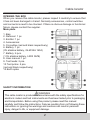 2
2
-
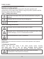 3
3
-
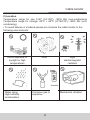 4
4
-
 5
5
-
 6
6
-
 7
7
-
 8
8
-
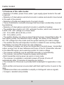 9
9
-
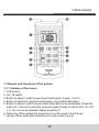 10
10
-
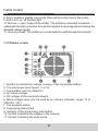 11
11
-
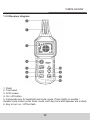 12
12
-
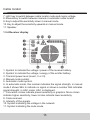 13
13
-
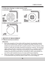 14
14
-
 15
15
-
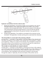 16
16
-
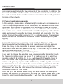 17
17
-
 18
18
-
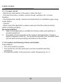 19
19
-
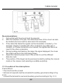 20
20
-
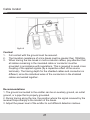 21
21
-
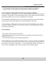 22
22
-
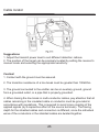 23
23
-
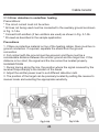 24
24
-
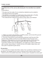 25
25
-
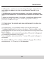 26
26
-
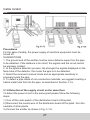 27
27
-
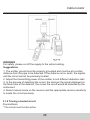 28
28
-
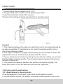 29
29
-
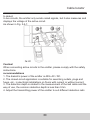 30
30
-
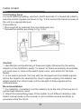 31
31
-
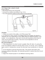 32
32
-
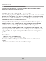 33
33
-
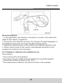 34
34
-
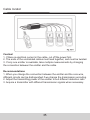 35
35
-
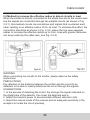 36
36
-
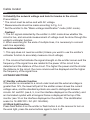 37
37
-
 38
38
-
 39
39
-
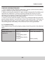 40
40
-
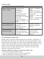 41
41
-
 42
42
-
 43
43
-
 44
44
-
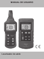 45
45
-
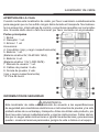 46
46
-
 47
47
-
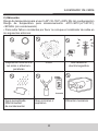 48
48
-
 49
49
-
 50
50
-
 51
51
-
 52
52
-
 53
53
-
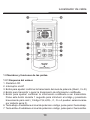 54
54
-
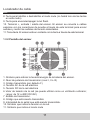 55
55
-
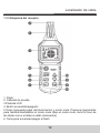 56
56
-
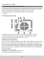 57
57
-
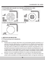 58
58
-
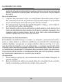 59
59
-
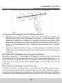 60
60
-
 61
61
-
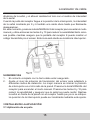 62
62
-
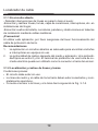 63
63
-
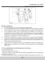 64
64
-
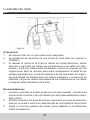 65
65
-
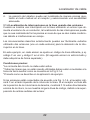 66
66
-
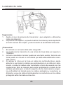 67
67
-
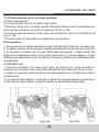 68
68
-
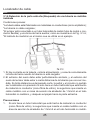 69
69
-
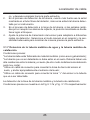 70
70
-
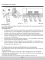 71
71
-
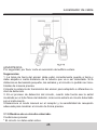 72
72
-
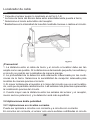 73
73
-
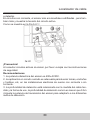 74
74
-
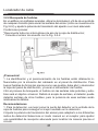 75
75
-
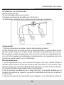 76
76
-
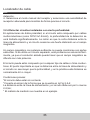 77
77
-
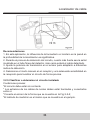 78
78
-
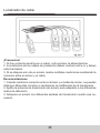 79
79
-
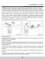 80
80
-
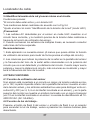 81
81
-
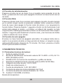 82
82
-
 83
83
-
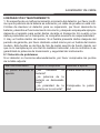 84
84
-
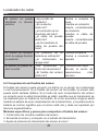 85
85
-
 86
86
-
 87
87
-
 88
88


KPS CC840 El manual del propietario
- Tipo
- El manual del propietario
- Este manual también es adecuado para
En otros idiomas
- English: KPS CC840 Owner's manual
Otros documentos
-
DirekTronik 20114258 Guía del usuario
-
koban KCL-01 Manual de usuario
-
Yamaha RX-V2090 Manual de usuario
-
ESAB M3® Plasma Smart Voltage Height Control Manual de usuario
-
-
-
Philips SRU4000 El manual del propietario
-
-
Marmitek GV580 Manual de usuario
-