Kichler Lighting 42589BK Manual de usuario
- Tipo
- Manual de usuario

Date Issued: 09/14/17 IS-42589-US
We’re here to help 866-558-5706
Hrs: M-F 9am to 5pm EST
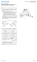
NOTE: Fixture may be installed as a ceiling mount or wall mount.
Adjust xture heads at swivels for desired direction.
1) Find the appropriate threaded holes on mounting strap[1]
that align with hole distance in canopy[2]. Thread mounting
screws[3] into threaded holes starting from outlet box[4] side.
2) Attach mounting strap to outlet box with strap mounting
screws[5]. Mounting strap can be adjusted to suit position of
xture.
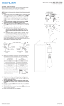
3) Grounding instructions: (See Illus. A or B)
A) On xtures where mounting strap is provided with a hole
and two raise dimples. Wrap ground wire from outlet box
around green ground screw, and thread into hole.
B) On xtures where a cupped washer is provided. Put
ground wire from outlet box under cupped washer and
green ground screw and thread screw into hole in mount-
ing strap.
If xture is provided with ground wire. Connect xture ground
wire to outlet box ground wire with wire connector, after follow-
ing the above steps. Never connect ground wire to black or
white power supply wires.
4) Make wire connections. Reference chart below for correct con-
nections and wire accordingly
GREEN GROUND
SCREW
CUPPED
WASHER
OUTLET BOX
GROUND
FIXTURE
GROUND
DIMPLES
WIRE CONNECTOR
OUTLET BOX
GROUND
GREEN GROUND
SCREW
FIXTURE
GROUND
A
B
Connect Black or
Red Supply Wire to:
Connect
White Supply Wire to:
Black White
*Parallel cord (round & smooth) *Parallel cord (square & ridged)
Clear, Brown, Gold or Black
without tracer
Clear, Brown, Gold or Black
with tracer
Insulated wire (other than green)
with copper conductor
Insulated wire (other than green)
with silver conductor
*Note: When parallel wires (SPT I & SPT II)
are used. The neutral wire is square shaped
or ridged and the other wire will be round in
shape or smooth (see illus.)
Neutral Wire
3
1
4
5
2
6
7
CAUTION – RISK OF SHOCK –
Disconnect Power at the main circuit breaker panel or main
fusebox before starting and during the installation.
5) Push xture to wall carefully passing mounting screws with
holes in canopy[2]. Make sure all wires are inside canopy and
do not get pinched between wall and canopy of xture.
6) Thread lockup knobs[6] and lockwashers[7] onto mounting
screws and tighten to secure xture to wall.
7) Insert recommended bulb (Not supplied).

Date Issued: 09/14/17 IS-42589-US
Estamos aquí para ayudarle 866-558-5706
Horario: Lunes-Viernes 9am a 5pm EST (hora ocial del este)
NOTA: El accesorio puede instalarse como montaje en techo o en
pared. Ajuste las cabezas de los accesorios en los giros para la
dirección deseada.
1) Encuentrelosoriciosroscadosadecuadosenlacorreade
montaje[1] que se alinean con la distancia del agujero en el
dosel[2] Enrosque los tornillos de montaje[3]enlosoricios
roscados desde el lado de la caja de salida[4].
2) Fije la correa de montaje a la caja de salida con los tornillos de
jacióndelacorrea[5]. La correa de montaje se puede ajustar
para adaptarse a la posición del aparato.
3) Instrucciones para poner a tierra: (Ver Ilustraciones A o B).
A) En artefactos donde se suministra la abrazadera de
montaje con un agujero y dos depresiones onduladas.
Envuelva el conductor de tierra de la caja de salida
alrededor del tornillo de tierra verde y atornille en el
agujero.
B) En artefactos donde se suministra una arandela
cóncava. Fije el conductor de tierra de la caja de salida
debajo de la arandela cóncava y el tornillo de tierra
verde y enrosque en la abrazadera de montaje.
Si se suministra el artefacto con conductor de tierra. Conecte
el conductor de tierra del artefacto al conductor de tierra de
la caja de salida con conector de tierra después de seguir los
pasos anteriores. Nunca conecte el conductor de tierra a los
alambres de alimentación eléctrica negros o blancos.
ARANDELA
CONCAVA
TIERRA DE LA
CAJA DE SALIDA
TORNILLO DE TIERRA,
VERDE
DEPRESIONES
TIERRA
ARTEFACTO
CONECTOR DE ALAMBRE
TIERRA DE LA
CAJA DE SALIDA
TORNILLO DE TIERRA,
VERDE
TIERRA
ARTEFACTO
A
B
PRECAUCIÓN – RIESGO DE DESCARGA ELÉCTRICA –
Desconecte la electricidad en el panel principal del interruptor
automático o caja principal de fusibles antes de comenzar y
durante la instalación.
3
1
4
5
2
6
7
4) Haga las conexiones de los alambres. Re érase a la tabla de
abajopararealizarlasconexionescorrectasdeloscables.
5) Empujelajaciónalaparedpasandocuidadosamentelostor-
nillosdemontajeconlosoricioseneldosel[2]. Asegúrese de
que todos los cables estén dentro del dosel y que no queden
atrapados entre la pared y el dosel del aparato.
6) Controles de bloqueo de rosca[6] y arandelas de seguridad[7]
enlostornillosdemontajeyaprieteparajarelaparatoala
pared.
7) Inserte la bombilla recomendada (No incluido).
Conectar el alambre de
suministro negro o rojo al
Conectar el alambre de
suministro blanco al
Negro Blanco
*Cordon paralelo (redondo y liso)
*Cordon paralelo (cuadrado y estriado)
Claro, marrón, amarillio o negro
sin hebra identificadora
Claro, marrón, amarillio o negro
con hebra identificadora
Alambre aislado (diferente del verde)
con conductor de cobre
Alambre aislado (diferente del
verde) con conductor de plata
*Nota: Cuando se utiliza alambre paralelo
(SPT I y SPT II). El alambre neutro es de forma
cuadrada o estriada y el otro alambre será de
forma redonda o lisa. (Vea la ilustracíón).
Hilo Neutral
-
 1
1
-
 2
2


Kichler Lighting 42589BK Manual de usuario
- Tipo
- Manual de usuario
En otros idiomas
- English: Kichler Lighting 42589BK User manual
Documentos relacionados
-
 Kichler Lighting 49893OZ Manual de usuario
-
 Kichler Lighting 45889NI Manual de usuario
-
 Kichler Lighting 49960AVI Manual de usuario
-
 Kichler Lighting 49874WZC Manual de usuario
-
 Kichler Lighting 49873WZC Manual de usuario
-
 Kichler Lighting 44100CLP Manual de usuario
-
 Kichler Lighting 43196BK Manual de usuario
-
 Kichler Lighting 44217CLP Manual de usuario
-
 Kichler Lighting 49875WZC Manual de usuario


