ACE 21D-64M1066 El manual del propietario
- Categoría
- Mini cultivadores
- Tipo
- El manual del propietario
Este manual también es adecuado para

Safe Operation Practices • Set-Up • Operation • Maintenance • Service • Troubleshooting • Warranty
®
ATORrS
ANUAL
Bronco, Super Bronco & Pro=Line CRT Tillers
TROY=BILT LLC, P.O. BOX 361131 CLEVELAND, OHiO 44136=0019
PrintedInUSA FormNo.769-07548
(December13,2011)

ToTheOwner
1
ThankYou
Thank you for purchasing a Troy-Bilt Tiller. It was carefully
engineered to provide excellent performance when properly
operated and maintained.
Please read this entire manual prior to operating the equipment.
It instructs you how to safely and easily set up, operate and
maintain your machine. Please be sure that you, and any other
persons who will operate the machine, carefully follow the
recommended safety practices at all times. Failure to do so could
result in personal injury or property damage.
All information in this manual is relative to the most recent
product information available at the time of printing. Review
this manual frequently to familiarize yourself with the machine,
its features and operation. Please be aware that this Operator's
Manual may cover a range of product specifications for various
models. Characteristics and features discussed and/or illustrated
in this manual may not be applicable to all models. We reserve
the right to change product specifications, designs and
equipment without notice and without incurring obligation.
If applicable, the power testing information used to establish
the power rating of the engine equipped on this machine can be
found at www.opei.org or the engine manufacturer's web site.
If you have any problems or questions concerning the machine,
phone a authorized Troy-Bilt service dealer or contact us directly.
Troy-Bilt's Customer Support telephone numbers, website
address and mailing address can be found on this page. We want
to ensure your complete satisfaction at all times.
Throughout this manual, all references to right and left side of the
machine are observed from the operating position
The engine manufacturer is responsible for all engine-related
issues with regards to performance, power-rating, specifications,
warranty and service. Please refer to the engine manufacturer's
Owner's/Operator's Manual, packed separately with your
machine, for more information.
1"able of Contents
Safe Operation Practices ........................................ 3
Assembly & Set-Up .................................................. 7
Control & Features ................................................. 10
Operation ................................................................ 11
Maintenance & Adjustment ................................. 13
Service ..................................................................... 17
Troubleshooting ..................................................... 19
Replacement Parts ................................................ 20
Warranty .................................................. Back Cover
EecordProduct information
Before setting up and operating your new equipment, please
locate the model plate on the equipment and record the
information in the provided area to the right. You can locate the
model plate by standing at the operator's position and looking
down at the front right corner of the tine shield. This information
will be necessary, should you seek technical support via our web
site, Customer Support Department, or with a local authorized
service dealer.
MODEL NUMBER
[3131313131313131313D
SERIALNUMBER
[3D[3D[3D[3D[3DD
CustomerSupport
Please do NOT return the machine to the retailer or dealer without first contacting the Customer Support Department.
If you have difficulty assembling this product or have any questions regarding the controls, operation, or maintenance of
this machine, you can seek help from the experts. Choose from the options below:
0 Visit us on the web at www.troybilt.com
See How-to Maintenance and Parts Installation Videos at www.troybilt.com/tutorials
0 Call a Customer Support Representative at (800) 828-5500 or (330) 558-7220
0 Write to Troy-Bilt LLC • RO. Box 361131 • Cleveland, OH • 44136-0019

ImportantSafeOperationPractices
2
WARNING! This symbol points out important safety instructions which, if not followed,
could endanger the personal safety and/or property of yourself and others. Read and follow
all instructions in this manual before attempting to operate this machine. Failure to comply
with these instructions may result in personal injury.
When you see this symbol. HEED ITS WARNING!
CALIFORNIA PROPOSITION 65
_1 ARNING! Engine Exhaust, some of its constituents, and certain vehicle components
contain or emit chemicals known to State of California to cause cancer and birth defects
or other reproductive harm.
_ ARNINGI Battery posts, terminals, and related accessories contain lead and lead
compounds, chemicals known to the State of California to cause cancer and reproductive
harm. Wash hands after handling
DANGER! This machine was built to be operated according to the safe operation practices in
this manual. As with any type of power equipment, carelessness or error on the part of the
operator can result in serious injury. This machine is capable of amputating fingers, hands,
toes and feet. Failure to observe the following safety instructions could result in serious
injury or death.
Training 2.
1. Read, understand, and follow all instructions on the
machine and in the manual(s) before attempting to
assemble and operate. Keep this manual in a safe place for
future and regular reference and for ordering replacement
parts.
2. Be familiar with all controls and their proper operation.
Know how to stop the machine and disengage them
quickly.
3. Never allow children under 14 years of age to operate this
machine. Children 14 and over should read and understand
the instructions and safe operation practices in this manual
and on the machine and be trained and supervised by an
adult.
4.
5.
Never allow adults to operate this machine without proper
instruction.
Keep the area of operation clear of all persons, particularly
small children and pets. Stop machine if anyone enters the
atea.
Preparation
1.
Thoroughly inspect the area where the equipment is to
be used. Remove all stones, sticks, wire, and other foreign
objects which could be tripped over and cause personal
injury.
Wear sturdy, rough-soled work shoes and close fitting
slacks and shirt. Loose fitting clothes or jewelry can be
caught in moving parts. Never operate this machine in bare
feet or sandals.
3. Disengage clutch levers and shift (if provided) into neutral
("N") before starting the engine.
4. Never leave this machine unattended with the engine
running.
5. Never attempt to make any adjustments while engine is
running, except where specifically recommended in the
operator's manual.
SafeHandling 0f Gas01ine:
To avoid personal injury or property damage use extreme care
in handling gasoline. Gasoline isextremely flammable and the
vapors are explosive. Serious personal injury can occur when
gasoline is spilled on yourself or your clothes which can ignite.
Wash your skin and change clothes immediately.
a. Use only an approved gasoline container.
b. Never fill containers inside a vehicle or on a truck
or trailer bed with a plastic liner. Always place
containers on the ground away from your vehicle
before filling.

d_
e_
f.
g.
When practical, remove gas-powered equipment
from the truck or trailer and refuel it on the ground.
If this is not possible, then refuel such equipment on
a trailer with a portable container, rather than from a
gasoline dispenser nozzle.
Keep the nozzle in contact with the rim of the fuel
tank or container opening at all times until fueling is
complete. Do not use a nozzle lock-open device.
Extinguish all cigarettes, cigars, pipes and other
sources of ignition.
Never fuel machine indoors.
Never remove gas cap or add fuel while the engine
is hot or running. Allow engine to cool at least two
minutes before refueling.
h. Never over fill fuel tank. Fill tank to no more than 1/2
inch below bottom of filler neck to allow space for
fuel expansion.
i. Replace gasoline cap and tighten securely.
j. If gasoline is spilled, wipe it off the engine and
equipment. Move unit to another area. Wait 5
minutes before starting the engine.
k. To reduce fire hazards, keep machine free of grass,
leaves, or other debris build-up. Clean up oil or fuel
spillage and remove any fuel soaked debris.
I. Never store the machine or fuel container inside
where there is an open flame, spark or pilot light
as on a water heater, space heater, furnace, clothes
dryer or other gas appliances.
Operation
1. Do not put hands or feet near rotating parts. Contact with
the rotating parts can amputate hands and feet.
2. Do not operate machine while under the influence of
alcohol or drugs.
3. Never operate this machine without good visibility or light.
Always be sure of your footing and keep a firm hold on the
handles.
4. Keep bystanders away from the machine while it is in
operation. Stop the machine if anyone enters the area.
5. Be careful when tilling in hard ground. The tines may catch
in the ground and propel the tiller forward. If this occurs,
letgo of the handle bars and do not restrain the machine.
6. Exercise extreme caution when operating on or crossing
gravel surfaces. Stay alert for hidden hazards or traffic. Do
not carry passengers.
7. Never operate the machine at high transport speeds on
hard or slippery surfaces.
8. Exercise caution to avoid slipping or falling.
9. Look down and behind and use care when in reverse or
pulling machine towards you.
10. Start the engine according to the instructions found in this
manual and keep feet well away from the tines at all times.
14.
15.
11. After striking a foreign object, stop the engine, disconnect
the spark plug wire and ground against the engine.
Thoroughly inspect the machine for any damage. Repair
the damage before starting and operating.
12. Disengage all clutch levers (if fitted) and stop engine
before you leave the operating position (behind the
handles). Wait until the tines come to a complete stop
before unclogging the tines, making any adjustments, or
inspections.
13. Never run an engine indoors or in a poorly ventilated area.
Engine exhaust contains carbon monoxide, an odorless
and deadly gas.
Muffler and engine become hot and can cause a burn. Do
not touch.
Use caution when tilling near fences, buildings and
underground utilities. Rotating tines can cause property
damage or personal injury.
16. Do not overload machine capacity by attempting to till soil
too deep at too fast of a rate.
17. If the machine should start making an unusual noise or
vibration, stop the engine, disconnect the spark plug wire
and ground it against the engine. Inspect thoroughly for
damage. Repair any damage before starting and operating.
18. Keep all shields, guards, and safety devices in place and
operating properly.
19. Never pick up or carry machine while the engine is running.
20. Use only attachments and accessories approved by the
manufacturer. Failure to do so can result in personal injury.
21. If situations occur which are not covered in this manual, use
care and good judgement. Contact Customer Support for
assistance and the name of you nearest servicing dealer..
Maintenance & Storage
1. Keep machine, attachments and accessories in safe
working order.
2. Allow a machine to cool at least five minutes before
storing. Never tamper with safety devices. Check their
proper operation regularly.
3. Check bolts and screws for proper tightness at frequent
intervals to keep the machine in safe working condition.
Also, visually inspect machine for any damage.
4. Before cleaning, repairing, or inspecting, stop the engine
and make certain the tines and all moving parts have
stopped. Disconnect the spark plug wire and ground it
against the engine to prevent unintended starting.
5. Do not change the engine governor settings or over-speed
the engine. The governor controls the maximum safe
operating speed of engine.
6. Maintain or replace safety and instruction labels, as
necessary.
7. Follow this manual for safe loading, unloading,
transporting, and storage of this machine.
8. Always refer to the operator's manual for important details
if the machine is to be stored for an extended period.
4 J SECTION 2 -- IMPORTANT SAFE OPERATION PRACTICES

9_
10.
11.
If the fuel tank has to be drained, do this outdoors.
Observe proper disposal laws and regulations for gas, oil,
etc. to protect the environment.
According to the Consumer Products Safety Commission
(CPSC) and the U.S. Environmental Protection Agency (EPA),
this product has an Average Useful Life of seven (7) years,
or 130 hours of operation. At the end of the Average Useful
Life have the machine inspected annually by an authorized
service dealer to ensure that all mechanical and safety
systems are working properly and not worn excessively.
Failure to do so can result in accidents, injuries or death.
Notice Regarding Emissions
Engines which are certified to comply with California and federal
EPA emission regulations for SORE (Small Off Road Equipment)
are certified to operate on regular unleaded gasoline, and
may include the following emission control systems: Engine
Modification (EM), Oxidizing Catalyst (OC), Secondary Air
Injection (SAI) and Three Way Catalyst (TWC) if so equipped.
SparkArrestor
WARNING! This machine is equipped with an
internal combustion engine and should not be used
on or near any unimproved forest-covered,
brushcovered or grass-covered land unless the
engine's exhaust system is equipped with a spark
arrestor meeting applicable local or state laws (if
any).
Ira spark arrestor is used, it should be maintained in effective
working order by the operator. In the State of California the
above is required by law (Section 4442 of the California Public
Resources Code). Other states may have similar laws. Federal laws
apply on federal lands.
A spark arrestor for the muffler is available through your
nearest engine authorized service dealer or contact the service
department, P.O.Box 361131 Cleveland, Ohio 44136-0019.
SECTION 2 -- IMPORTANT SAFE OPERATION PRACTICES S

SafetySymbols
This page depicts and describes safety symbols that may appear on this product. Read, understand, and follow all instructions on the
machine before attempting to assemble and operate.
A
READ THE OPERATOR'S MANUAL(S)
Read, understand, and follow all instructions in the manual(s) before attempting to
assemble and operate
WARNING-- ROTATING TINES
Do not put hands or feet near rotating parts. Contact with the rotating parts can amputate
hands and feet.
WARNING-- ROTATING TINES
Do not put hands or feet near rotating parts. Contact with the rotating parts can amputate
hands and feet.
WARNING--GASOLINE IS FLAMMABLE
Allow the engine to cool at least two minutes before refueling.
WARNING-- CARBON MONOXIDE
Never run an engine indoors or in a poorly ventilated area. Engine exhaust contains carbon
monoxide, an odorless and deadly gas.
WARNING-- HOT SURFACE
Engine parts, especially the muffler, become extremely hot during operation. Allow engine
and muffler to cool before touching.
WARNING! Your Responsibility--Restrict the use of this power machine to persons who read, understand and
follow the warnings and instructions in this manual and on the machine.
SAVETHESEINSTRUCTIONS!
6 I SECTION 2 -- IMPORTANT SAFE OPERATION PRACTICES

Assembly& Set-Up
3
Contents of Carton
OneTiller
One Operator's Manual
One 20 oz. Bottle SAE 10W30 Oil
One Engine Operator's Manual
One Handlebar Assembly
NOTE:This Operator's Manual covers several garden tiller
models. The tiller depicted may differ from yours.
WARNING! To prevent personal injury or property
damage, do not start the engine until all assembly
steps are complete and you have read and
understand the safety and operating instructions in
this manual.
RecommendedToolsfor Assembly
Two 1/2"open-end wrenches
Block of wood (to support tiller when removing wheels)
Tire pressure gauge
Clean oil funnel
Motor oil. Refer to the Engine Operator's Manual for oil
specifications and quantity required.
Assembly
UnpackingInstructions
NOTE:While unpacking, do not severely bend any of the control
cables.
1. The tiller is heavy, do not attempt to remove it from
the shipping platform until instructed to do so in these
Assembly steps.
2. Remove any packaging material from the carton. Remove
any staples from the bottom of the carton and remove the
carton from the shipping platform.
3. Remove all loose parts from the carton. Check that you
have the items listed in the Contents of Carton list (contact
your local dealer or the factory if items are missing or
damaged).
Handle
NOTE:All references to the right or left side of the tiller are from
the operator's position.
1. Remove two hex screws (sA6-18x 1.50), two flange lock
nuts (sA6-18),carriage bolt (sA6-18x 6.75), bell washer (.326 x
.875 x .145) and knob (sA6-18)from the lower handlebar and
support brackets. See Fig. 3-1.
Lower
Flange
Lock
Nuts
Hex Screw
Figure 34

2.
3.
Using two hex screws and two flange lock nuts, loosely
attach the handlebar support using the upper holes.
Tighten the two screws securely. See Fig. 3-2.
Upper Handle
He× Screw
eLock Nut
Figure 3-2
Loosely attach the support brackets to the outside of the
handlebar assembly using the carriage bolt, bell washer
and knob. Refer to Fig. 3-3.
Knob
Carriage Bolt Bell Washer
Figure 3-3
NOTE: If a support bracket will not move, loosen the
attaching hex screws (sA6-18x .75) and flange lock nuts (sA6-
18) at the base of the support brackets.
NOTE:The support brackets must be assembled to the
outside of the handlebar assembly.
4.
F
There are three height adjustment holes in the handlebar
support bracket. Use a setting that will position the
handlebars at approximately waist level when the tines are
3-4" into the soil. To adjust the height of the handlebars
loosen the knob on the handle, pull out on the carriage
screw, adjust to the desired setting, push the carriage
screw in until the square portion of the screw locks into
place and re-tighten the knob. See Fig. 3-4.
Carriage Screw
Figure 3-4
4. Tighten all the handlebar mounting hardware securely.
Move Tiller Off Crate
To roll the tiller off the shipping platform, put the wheels in
freewheel, as follows:
1. Place a sturdy block under the transmission to raise one
wheel about 1" off the ground.
2. Remove the wheel drive pin from the wheel hub and wheel
shaft. See Fig. 3-5.
f- -,_
Wheel Shaft
Wheel Drive Pin
Figure 3=5
8 I SECTION3-- ASSEMBLY& SET-UP

3.
Slide the wheel fully inward on the wheel shaft. Reinstall
the wheel drive pin through the wheel shaft only (not
through the wheel hub). See Fig. 3-5. The wheel should
now spin freely (freewheel) on the wheel shaft. Repeat with
the other wheel.
4. Use the handlebar to roll the tiller to a flat area.
NOTE: Before starting the engine, the wheels must be placed in
the WHEEL DRIVE position (pins through wheel hubs and wheel
shaft).
Forward ClutchCable
1.
Carefully unwrap the forward clutch cable from its shipping
)osition. Pull the cable up through the bottom hole of the
cable bracket and push the cable connector up through
the hole until the groove in the connector snaps into place.
See Fig, 3-6.
Z=Connector .............
2.
Figure 3-6
Place the Z-connector into the hole in the forward clutch
bail from the outside of the bail to the inside. See Fig. 3-6.
ReverseClutchCable(If s0equipped)
1. Carefully unwrap the reverse clutch cable (Red end fitting)
from its shipping position. Pull the cable up through the
top hole of the cable bracket and push the cable connector
up through the hole until the groove in the connector
snaps into place. See Fig. 3-7.
Z=Connector
2.
Figure 3-7
Place the Z-connector into the hole in the reverse clutch
handle assembly from the inside of the handle to the
outside. See Fig. 3-7.
Set-tip
TirePressure
Check the air pressure with a tire gauge. Deflate or inflate the
tires equally to between 15and 20 PSI.
NOTE: Be sure that both tires are inflated equally or the tiller will
pull to one side.
Gas& OilFill Up
WARNING! Use extreme care when handling
gasoline. Gasoline is extremely flammable and the
vapors are explosive. Never fuel the machine
• indoors or while the engine is hot or running.
Extinguish cigarettes, cigars, pipes and any other
sources of ignition.
Service the engine with gasoline and oil as instructed in the
Engine Operator's Manual packed separately with your tiller.
Read the instructions carefully.
SECTION 3 -- ASSEMBLY& SET-UP 9

Controls& Features
4
Reverse Handle Assembb
Forward Clutch
ulator Lever
ight Adjustment
Tines
Drive Pin
NOTE:This Operator's Manual covers several garden tiller
models. The tiller depicted may differ from yours.
EngineControLs
Figure 4=1
ReverseHandleAssembly(i[ soequipped)
The reverse handle assembly controls the engagement of the
reverse drive of the wheels and tines.
For detailed information on all engine controls refer to the
separate Engine Operator's Manual.
WheelDrive Pins
Each wheel is equipped with a wheel drive click pin that secures
the wheel to the wheel shaft. The wheels can be positioned in
either a wheel drive or a freewheel mode.
ForwardClutchBail
The forward clutch bail controls the engagement of the forward
drive of the wheels and tines.
Depth Regulator Lever
This lever controls the tilling depth of the tines.
Pull the lever back and slide it up or down to
engage the notched height settings.
Handlebar Height Adjustment
The handlebar height is adjustable to three different settings. In
general, adjust the handlebars so they are at waist level when the
tines are 3-4" in the ground.

Operation
WARNING! Before operating your machine,
carefully read and understand this manual and all of
its safety, operating and maintenance sections and
instructions, along with all of the decals on the
machine. Failure to follow these instructions can
result in serious personal injury.
Introduction
Read this Operation Section and the Engine Operator's Manual
before you start the engine. Then, take the time to familiarize
yourself with the basic operation of the tiller before using it in
the garden.
Find an open, level area and practice using the tiller controls
without the tines engaging the soil (put tines in "transport"
setting).
Only after you've become completely familiar with the tiller
should you begin using it in the garden.
Break-inOperation
Perform the following maintenance after the first five (5) hours of 1.
new operation (see Maintenance & Adjustments Section in this 2.
manual). 3.
1. Change engine oil.
2. Check for loose or missing hardware on the tiller. Tighten
or replace as needed.
3. Check transmission gear oil level. See the Maintenance &
Adjustments section.
Startingthe Engine
Pre-StartChecklist
3.
4.
5.
6.
With the spark plug wire disconnected from the spark plug,
perform the following checks and services before each use:
1. Read the Safe Operation Practices and the Features &
Controls Section in this manual. Read the separate Engine
Operator's Manual provided with the tiller.
2. Put the wheels in the WHEEL DRIVE position (wheel pins
must be through holes in wheel hubs and wheel shaft).
WARNING. Never allow either of the wheels to be
in the freewheel position when the engine is
running. Always put both wheels in the wheel drive
position before starting the engine. Failure to
comply could cause loss of tiller control, property
damage or personal injury.
Check the tiller for loose or missing hardware. Service as
required.
Check the engine oil level. See the Engine Operator's
Manual.
Check that all the safety guards and covers are in place.
Check the air cleaner and engine cooling system. See the
Engine Operator's Manual.
7. Fill the fuel tank with gasoline according to the directions
in the separate Engine Operator's Manual. Follow all
instructions and safety rules carefully.
8. If necessary, Attach the spark plug wire to the spark plug.
Starting the Engine
WARNING!To help prevent serious personal injury or
damage to equipment, put both wheels in the WHEEL
DRIVE position. Never have wheels in FREEWHEEL
position when the engine is running. When the wheels
are in FREEWHEEL, they do not hold back the tiller and
the tines could propel the tiller rapidly forward or
backward. Put the Forward Clutch Bail in neutral
(disengaged) positions by releasing the lever.
WARNING! Never run the engine indoors or in an
enclosed, poorly ventilated area. Engine exhaust
contains carbon monoxide, an odorless and deadly
gas. Avoid the engine muffler and nearby areas.
Temperatures in these areas may exceed 150° F.
Complete the Pre-Start Checklist above on this page.
Put the wheels in the WHEEL DRIVE position.
Move the depth regulator lever all the way down to the
"travel" position, so that the tines clear the ground. To
change the depth setting, pull back on the depth regulator
lever (A) and lift up or down (B), then release the lever (C) to
secure in the desired position. See Fig, 5-1.
Figure 5-1
4. Release all of the controls on the tiller.
5. Start the engine as instructed in the Engine Operator's Manual.
Stoppingthe Engine
I. To stop the wheels and tines, release the Forward Clutch Bail.
2. Refer to the Engine Operator's Manual for instructions on
stopping the engine.
11

12
EngageDrive& Tines
1. For forward motion ofthe wheels and power to the tines pull
the Forward Clutch Bail up against the handlebar. Release
the bail to stop the forward motion of the wheels and tines.
2. When tilling, relax and let the wheels pull the machine while
the tines dig. Walk behind and a little to one side of the tiller.
Use one hand, yet keep a light-- but secure -- grip on the
handlebar (while keeping your arm loose). See Fig. 5-2. Let
the tiller move at its own pace and do not push down on the
handlebars to try and force the tines to dig deeper-- this
takes weight offthe wheels and reduces traction.
Reverse Handle
Figure 5-2
WARNING! Donot pushdown onthe handlebarstotry
to makethe tillertill moredeeply.Thispreventsthewheels
from holdingthe tillerbackand canallowthetinesto
rapidlypropel thetillerforward,whichcould resultin lossof
control,propertydamage,or personalinjury.
3. To move in reverse:
a. On models with reverse handle:
Look behind and exercise caution when
operating in reverse. Do not till while in reverse.
Stop all forward motion. Lift the handlebar
with one hand until the tines are off the ground
and then pull the Reverse Handle back. To stop
reversing, let go of the Reverse Handle.
If longer distances need to be covered in reverse,
shut offthe engine, then place the two wheels in
freewheel.
b. On models without reverse handle:
Release the forward clutch bail. Then lift the
handlebar until the tines are off the ground.
Swing the handlebar to the left so the right
wheel takes a "step" backward. Next swing the
handlebar to the right so the left wheel "steps"
backward. Repeat as needed.
If longer distances need to be covered in
reverse, shut offthe engine, then place the two
wheels in freewheel.
I
SECTION S-- OPERATION
Turningthe Tiller
Practice turning the tiller in a level, open area. Be very careful to
keep your feet and legs away from the tines.
1. To begin a turn, lift the handlebars until the tines are out of
the ground and the engine and tines are balanced over the
wheels. See Fig. 5-3.
J
Figure 5-3
2. With the tiller balanced, push sideways on the handlebar
to steer in the direction of the turn. See Fig. 5-3.
3. After turning, slowly lower the tines into the soil to resume
tilling. See Fig. 5-3.
Clearingthe Tines
The tines have a self-clearing action which eliminates most tangling
of debris in the tines. However, occasionally dry grass, stringy stalks
or tough vines may become tangled. Follow these procedures to
help avoid tangling and to clean the tines, if necessary.
To reduce tangling, set the depth regulator deep enough to
get maximum "chopping" action as the tines chop the material
against the ground. Also, try to till under crop residues or cover
crops while they are green, moist and tender.
While tilling, try swaying the handlebars from side to side (about
6" to 12").This "fishtailing" action often clears the tines of debris.
If tangling occurs, lift the tines out of the soil and run the
tiller in reverse for a few feet. This reversing action should
unwind a good deal of debris.
WARNING! Before clearing the tines by hand, stop
the engine, allow all moving parts to stop and
disconnect the spark plug wire. Failure to follow this
warning could result in personal injury.
TillingTips& Techniques
TillingDepth
WARNING! Before tilling, contact your telephone or
utilities company and inquire ifunderground equipment
or lines are used on your property. Do not till near buried
__ electric cables, telephone lines, pipes or hoses.
This is a CRT (counter-rotating tine) tiller. As the wheels
pull forward, the tines rotate backward. This creates an
"uppercut" tine action which digs deeply, uprooting soil
and weeds. Don't overload the engine, but dig as deeply as
possible on each pass. On later passes, the wheels may tend
to spin in the soft dirt. Help them along by lifting up slightly
on the handlebar (one hand, palm up, works most easily).

Avoidthetemptationtopushdownonthehandlebarsinan
attempttoforcethetillertodigdeeper.Doingsotakesthe
weightoffthepoweredwheels,causingthemtolosetraction.
Withoutthewheelstoholdthetillerback,thetineswill
attempttopropelthetillerbackward,towardstheoperator.
Whencultivating(breakingupsurfacesoilaroundplantsto
destroyweeds,seeFig.5-4),Adjustthetinestodigonly1"
to2"deep.Usingshallowtillingdepthshelpspreventinjury
totheplantswhoserootsoftengrowclosetothesurface.
Ifneeded,liftuponthehandlebarsslightlytopreventthe
tinesfromdiggingtoodeeply.(Cultivatingonaregularbasis
notonlyeliminatesweeds,italsoloosensandaeratesthe
soilforbettermoistureabsorptionandfasterplantgrowth.)
Wateringthegardenareaafewdayspriortotillingwillmake
tillingeasier,aswilllettingthenewlyworkedsoilsetfora
dayortwobeforemakingafinal,deeptillingpass.
Whenfinishedinonedirection,makeasecondpassat
arightangle,asshowninFig.5-6.Overlapeachpassfor
bestresults(inveryhardground,itmaytakethreeorfour
passestothoroughlypulverizethesoil.)
_m
IIIimll _ mllmlm IImm
Imam
f
J
Figure 5-6
If the garden size will not permit lengthwise and then crosswise
tilling, overlap the first passes by one-half a tiller width, followed
by successive passes at one-quarter width. See Fig. 5-7.
Figure 5-4
SuggestedTilling Patterns
When preparing a seedbed, go over the same path twice in
the first row, then overlap one-half the tiller width on the
rest of the passes. See Fig. 5-5.
Figure 5-7
Figure 5-5 SECTION S -- OPERATION 13

Tilling ona Slope
WARNING! Do not operate the tiller on a slope too
steep for safe operation. Till slowly and be sure you
have good footing. Never permit the tiller to
freewheel down slopes. Failure to follow this
warning could result in personal injury.
1. Till only on moderate slopes, never on steep ground where
the footing is difficult.
2. Tilling up and down slopes is recommended rather than
terracing. Tilling vertically on a slope allows maximum
planting area and also leaves room for cultivating.
NOTE:when tilling on slopes, be sure the correct oil level
is maintained in the engine (check every one-half hour
of operation). The incline of the slope will cause the oil to
slant away from its normal level and this can starve engine
parts of the required lubrication. Keep the motor oil level at
the full point at all times.
Tilling Up& D0wna Slope
1. To keep soil erosion to a minimum, be sure to add enough
organic matter to the soil so that it has good moisture-holding
texture and try to avoid leaving footprints or wheel marks.
2. When tilling vertically, try to make the first pass uphill as the
tiller digs more deeply going uphill than it does downhill.
In soft soil or weeds, you may have to lift the handlebars
slightly while going uphill. When going downhill, overlap the
first pass by about one-half the width of the tiller.
TerraceGardening
1. To create a terrace, start at the top of the slope and work down.
Go backand forth across the first rowas shown in Fig. 5-8.
Figure 5-8
2. Each succeeding lower terrace is started by walking below
the terrace you're preparing. For added stability of the
tiller, always keep the uphill wheel in the soft, newly tilled
soil. Do not till the last 12" or more of the downhill outside
edge of each terrace. This untilled strip helps prevent the
terraces from breaking apart and washing downhill. It also
provides a walking path between rows.
Loading& Unloadingthe tiller
WARNING! Loading and unloading the tiller into a
vehicle is potentially hazardous and doing so is not
recommended unless absolutely necessary, as this
could result in personal injury or property damage.
If it is necessary to load or unload the tiller, follow these guidelines.
Stop the engine, wait for all parts to stop moving,
disconnect the spark plug wire and let the engine and
muffler cool.
The tiller is too heavy and bulky to be lifted safely by one
person. Two or more people should share the load.
Use sturdy ramps and manually -- with the engine shut
off-- roll the tiller into and out of the vehicle. Two or more
people are needed to do this.
The ramps must be strong enough to support the combined
weight of the tiller and any handlers. The ramps should
provide good traction to prevent slipping, they should have
side rails to guide the tiller along the ramps and they should
have a locking device to secure them to the vehicle.
The handlers should wear sturdy footwear that will help
prevent slipping.
Position the loading vehicle so that the ramp angle is as flat
as possible (the less incline to the ramp, the better). Turn
the vehicle's engine off and apply its parking brake.
When going up ramps, stand in the normal operating
position and push the tiller ahead of you. Have a person at
each side to turn the wheels.
When going down ramps, walk backward with the tiller
following you. Keep alert for any obstacles behind you. Position
a person at each wheel to control the speed of the tiller. Never
go down ramps tiller-first, asthe tiller could tip forward.
Place wooden blocks on the downhill side of the wheels
if you need to stop the tiller from rolling down the ramp.
Also, use the blocks to temporarily keep the tiller in place
on the ramps (if necessary), and to chock the wheels in
place after the tiller is in the vehicle.
After loading the tiller, prevent it from rolling by engaging
the wheels in the wheel drive position. Chock the wheels
with blocks and securely tie the tiller down.
SECTION S-- OPERATION

Maintenance&Adjustments
MaintenanceSchedule
Check After
first 2 hours
Before each
use
Every
5 Hours
Every
10 Hours
Every
30 Hours
See Engine
Manual
CheckMotorOilLevel _
CleanEngine _
CheckDriveBeltTension _
CheckNutsandBolts M/ M/
LubricateTiller
CheckGear0il LevelinTransmission V/
CheckTinesforWear VII
CheckAirPressureinTires V/
WARNING! Before inspecting, cleaning or servicing
the machine, shut off the engine, wait for all moving
parts to come to a complete stop, disconnect the
spark plug wire and move the wire away from the
spark plug. Failure to follow these instructions can
result in serious personal injury or property damage.
Maintenance
Engine
Refer to the Engine Operator's Manual packed with your tiller for
all engine maintenance.
TirePressure
Check the air pressure in both tires. The air pressure should be
between 1,5-20 PSI. Keep both tires equally inflated to help
prevent machine from pulling to one side.
Hardware
Checkfor loose or missing hardware after every 10 operating
hours and tighten or replace (asneeded) before using tiller
Besure to check the screws underneath the tiller hood that
secure the transmission cover and the Depth Regulator Lever to
the transmission.
Lubrication
After every 10 operating hours, oil or grease the lubrication
points shown in Fig. 6-1 and described below.
Handlebar / /
\ J
Figure 64
15

Use a clean lubricating oil (#30 weight motor oil is suitable)
and a clean general purpose grease (grease containing a metal
lubricant is preferred, if available).
Remove the wheels, clean the wheel shaft and apply a thin
coating of grease to the wheel shaft.
Grease the back, front and sides of the depth regulator lever.
Remove the tines and clean the tine shaft. Use a file or
sandpaper to gently remove any rust, burrs or rough spots
(especially around holes in the shaft). Apply grease to the
ends of the shaft before installing the tines.
Oil the threads on the handlebar height adjustment screws
and the handlebar attaching screws.
TransmissionGearOil
Check the transmission gear oil after every 30 hours of operation
or whenever you notice any oil leak. Operating the tiller when
the transmission is low on oil can result in severe damage.
To Check the Transmission Gear Oil Level:
1. Check the gear oil level when the transmission is cool. Gear
oil will expand in warm operating temperatures and this
expansion will provide an incorrect oil level reading.
2. With the tiller on level ground, pull the Depth Regulator
Lever all the way up.
3. Clean the area around the oil fill plug. See Fig. 6-2.
i ' i
i
/'
Off-SeasonStorage
When the tiller won't be used for an extended period, prepare it
for storage as follows:
1. Clean the tiller and engine.
2. Do routine tiller lubrication and check for loose parts and
hardware.
3. Protect the engine and perform recommended engine
maintenance by following the storage instructions found
in the Engine Operator's Manual. Be sure to protect the
fuel lines, carburetor and fuel tank from gum deposits
by removing fuel or by treating fuel with a fuel stabilizer
(follow the engine manufacturer's recommendations).
4. Store the tiller in a clean, dry area.
5. Never store the tiller with fuel in the fuel tank in an
enclosed area where gas fumes could reach an open flame
or spark, or where ignition sources are present (space
heaters, hot water heaters, furnaces, etc.).
Figure 6-2
4. Remove the oil fill plug from the transmission housing and
look inside the oil fill hole to locate the main drive shaft
situated below the hole. See Fig. 6-2.
5. The gear oil level iscorrect if the gear oil isapproximately
halfway up the side of the main drive shaft.
6. If the gear oil level is low, add gear oil asdescribed next. If
the gear oil level is okay, securely replace the oil fill plug.
7. When adding gear oil, use Mobil 1®Synthetic 75W 140.
8. While checking frequently to avoid overfilling, slowly add
gear oil into the oil fill hole until it reaches the halfway
point on the drive shaft.
9. Securely replace the oil fill plug.
SECTION 6-- MAINTENANCE & ADJUSTMENTS

Service
7
Belt Replacement
If the drive belt or reverse drive belt needs to be replaced, see your 1.
local authorized dealer or refer to the Replacement Parts Section
for ordering information. Use only a factory-authorized belt as 2.
an "over- the-counter" belt may not perform satisfactorily. The
procedure requires average mechanical ability and commonly
available tools.
NOTE:When reinstalling the belt cover, be sure to engage the
bail and hold it so that the drive belt is tight before attempting to
reinstall the belt cover. This will enable the belt to fall under the
belt keeping mechanism built into the belt cover. Failure to do so
could damage the belt and/or belt cover.
Tines
The bolo tines will wear with use and should be inspected
at the beginning of each tilling season and after every 30
operating hours. The tines can be replaced either individually
or asa complete set. See the Replacement Parts Section for tine
identification and part numbers.
TineInspection
With use, the tines will become shorter, narrower and pointed.
Badly worn tines will result in a loss of tilling depth, and reduced
effectiveness when chopping up and turning under organic matter.
Refer to Fig. 7-1 for the following tine procedures.
Fro_l_nt/Forward
Flange Lock Nut J_
Hex Lock
Figure 7=1
Removing/Installing aSingleTine
1. With the engine shut off and the spark plug wire
disconnected, remove the two hex screws (3/8-16x 1.00)
and hex lock nuts (3/8-16)that attach a single tine to a tine
holder. If needed, use penetrating oil on the nuts.
2. When installing a single tine, be sure to position it so that
its cutting edge (sharp) will enter the soil first as the tiller
moves forward.
Rem0ving/Installing aTineAssembly:
A tine assembly consists of eight tines mounted on a tine
holder.
3.
4.
If removing both tine assemblies, mark them "left" and
"right" before removal. Remove the hex screw (3/8-16x 1.75)
and flange lock nut (3/8-16) that secure the tine assembly to
the tine shaft. If necessary, use a rubber mallet to tap the tine
assembly outward offthe shaft.
Before reinstalling the tine assembly, inspect the tine
shaft for rust, rough spots or burrs. Lightly file or sand, as
needed. Apply a thin coat of grease to the shaft.
Install each tine assembly so that the cutting (sharp) edge
of the tines will enter the soil first when the tiller moves
forward. Secure the tine assembly to the tine shaft using
the screw and Iocknut.
ChangeTransmissionGearOil
NOTE:The transmission gear oil does not need to be changed
unless it has been contaminated with dirt, sand or metal
particles.
1. Drain the gasoline from the fuel tank or run the engine
until the fuel tank is empty.
2. Drain the oil from the engine.
3. Remove the hex washer screw (1/4-20x .500) and flat washer
(.28 x .74 x .500) from the left side of the belt cover and the
hex washer screw (1A-20 x .500) from the right side of the
belt cover. Remove the belt coven See Fig. 7-2.
F
Hex Washer Screw
t j,
He×Washer Screw
Figure 7-2
17

4. Remove all dirt and clean the area around the transmission
cover. See Fig. 7-3.
5_
6_
7_
8.
Figure 7-3
Remove the four hex screws (sA6-18x .75) securing the
transmission cover to the drive shaft and remove the cover.
See Fig. 7-3
Remove the left-side wheel. Tilt the left-side wheel shaft
into a drain pan and allow the gear oil to drain through the
top of the transmission.
Reinstall the wheel and reinstall the transmission cover.
Refill the transmission using Mobil 1®Synthetic 75W 140.
Refill the engine with motor oil and replenish the fuel tank
with gasoline.
9. Reinstall the belt cover.
SECTION7-- SERVICE

Troubleshooting
Problem Cause ! Remedy
Tines turn, but wheels don't
Poor tilling performance
1. Wheel Drive Pins notin WHEEL DRIVE.
2. Bolt loose in transmission pulley.
3. Internal transmission wear or damage.
1. Worn tines.
2. Improper Depth Regulator setting.
3. Forward Drive Belt slipping.
1. Inserts Drive Pins properly.
2. Tighten bolt.
3. Contact local authorized dealer.
1. Replace Tines.
2. See "Tilling Tips &Techniques."
3. See Maintenance & Adjustments Section.
19

ReplacementParts
9
Component l Part Number and Description
954-04090
9.54-04091
946-04413
946-04414
742-04227
742-04226
934-04232
934-04453
Forward Drive Belt
Reverse Drive Belt (If so equipped)
Forward Drive Cable
Reverse Drive Cable (If so equipped)
Bolo Tine, 10"(LT)
Bolo Tine, 10"(RT)
Wheels 13 x5 x 6 (65M &655 model)
Wheels 11 x4-4 (64M model)
Phone (800) 828-5500 to order replacement parts or a complete Parts Manual (have your full model number and serial number ready).
Parts Manual downloads are also available free of charge at www.troybilt.com.

1
21

SECTION10--NOTES

SECTION10- NOTES 23

MANUFACTURER'S LiMiTED WARRANTY FOR
®
The limited warranty set forth below is given by Troy-Bilt LLCwith
respect to new merchandise purchased andused in the United States
and/or its territories and possessions, and by MTDProducts Limited
with respectto new merchandise purchasedand used in Canadaand/
or its territories and possessions (either entity respectively, "Troy-
Bilt").
"Troy-Bilt" warrants this product (excluding its Belts,Transmission
andAttachmentsas described below) against defects in material and
workmanship for a period of two (2) years commencing onthe date
of original purchase and will, at its option, repair or replace,free of
charge, any part found to be defective in materials or workmanship.
This limited warranty shall only apply if this product has been
operated and maintained inaccordance with the Operator's Manual
furnished with the product, and has not beensubject to misuse,
abuse, commercial use, neglect, accident, improper maintenance,
alteration, vandalism, theft, fire, water, or damage because of other
peril or natural disaster. Damage resulting from the installation or use
of any part, accessory or attachment not approved byTroy-Bilt for use
with the product(s) covered bythis manual will void your warranty as
to any resulting damage.
Belts arewarranted to befree from defects in material and
workmanship for a period of thirty (30) daysfrom the date of
purchase.
Transmission-- Troy-Bilt warrants the transmission (including
all gears, shafts and housings) against defects in material and
workmanship for the life of the tiller, to the original purchaser only,
commencing on the date of original purchase or lease.
Attachments--Troy-Bilt warrants attachments for this product
against defects in material andworkmanship for a period of one (1)
year, commencing on the date of the attachment's original purchase
or lease.Attachments include, but are not limited to items such as:
grass collectors and mulch kits.
HOWTO OBTAINSERVICE:Warranty service is available, WITH
PROOFOFPURCHASE,through your local authorized service dealer.
Tolocate the dealer in your area:
Jnthe U.S.A.
Checkyour Yellow Pages,or contact Troy-Bilt LLCat P.O.Box 361131,
Cleveland,Ohio 44136-0019, or call 1-866-840-6483,
1-330-558-7220 or log onto our Web site at www.troybilt.com.
In Canada
Contact MTDProducts Limited, Kitchener, ON N2G4J1, or call
1-800-668-1238 or log on to our Website at www.mtdcanada.com.
This limited warranty does not provide coverage in the following
cases:
a. Theengine or component parts thereof. These items may carry a
separate manufacturer's warranty. Referto applicable manufac-
turer's warranty for terms andconditions.
b. Log splitter pumps, valves, and cylinders havea separate one-
yearwarranty.
c. Routine maintenance items such as lubricants, filters, blade
sharpening, tune-ups, brake adjustments, clutch adjustments,
deck adjustments, and normal deterioration of the exterior finish
dueto use or exposure.
d. Service completed by someone other than an authorized service
dealer.
e. Troy-Bilt does not extend any warranty for products sold or
exported outside ofthe United States and/or Canada,andtheir
respective possessions and territories, exceptthose sold through
Troy-Bilt's authorized channels of export distribution.
f. Replacement parts that are not genuine Troy-Bilt parts.
g. Transportation charges and service calls.
h. Troy-Bilt does not warrant this product for commercial use.
No implied warranty, includingany implied warranty of
merchantability or fitness for a particular purpose,applies after
the applicable periodof express written warranty above as to the
parts as identified. No other express warranty, whether written or
oral, except as mentioned above, given by any personor entity,
includinga dealer or retailer, with respect to any product,shall
bind Troy-Bill. Duringthe periodof the warranty, the exclusive
remedy is repair or replacement of the productas set forth above.
The provisionsasset forth inthis warranty providethe sole and
exclusive remedy arising from the sale. Troy-Bill shall not be liable
for incidental orconsequential loss or damage including, without
limitation, expenses incurred for substitute or replacement lawn
careservices or for rental expenses to temporarily replace a
warranted product.
Some states do not allow the exclusion or limitation of incidental
or consequential damages, or limitations on how long an implied
warranty lasts, so the above exclusions or limitations may not apply
to you.
In no eventshall recovery of any kind begreater than the amount of
the purchase price of the product sold. Alteration of safety features of
the product shall void this warranty. You assume the risk and liability
for loss, damage, or injury to you and your property and/or to others
andtheir property arising out of the misuse or inability to use the
product.
This limited warranty shall not extend to anyone otherthan the
original purchaser or to the person for whom it was purchased as a
gift.
HOWSTATELAW RELATESTOTHISWARRANTY: This limited
warranty givesyou specific legal rights, and you may also haveother
rights which vary from stateto state.
IMPORTANT:Owner must present Original Proof of Purchase to
obtain warranty coverage.
Troy=Bilt LLC, P.O. BOX 361131 CLEVELAND, OHIO 44136-0019; Phone: 1=866-840=6483, 1=330=558W220
MTD Canada Limited = KITCHENER, ON N2G 4J1; Phone 1=800=668=1238
GD00-100023 REV.C

IVledidasimportantesdeseguridad•Conf_guraci6n• Funcionamiento• IVlantenimiento• Servicio• Soluci6ndeproblemas• Garantia
®
ANUAL EL
Bronco, Super Bronco & Pro-Line
Cuitivaclora de clientes traseros
TROY=BILT LLC, P.O. BOX 361131 CLEVELAND, OHiO 44136-0019
ImpresoenEstadosUnidosdeAm_rka
FormularioNo.769-07548
(Didembre13,2011)

A!propietario
1
Gracias
Gracias por comprar una Troy-Bilt cultivadora de jardin. La
misma ha sido dise_ada cuidadosamente para brindar excelente
rendimiento si se la opera y mantiene correctamente.
Pot favor lea todo este manual antes de operar el equipo.
Le indica c6mo configurar, operar y mantener la m_quina
con seguridad y f_cilmente. Pot favor asegOrese de seguir
cuidadosamente yen todo momento las pr_cticas de seguridad
recomendadas, y hac_rselas seguir a cualquier otra persona que
opere la m_quina. En caso de no hacerlo podrian producirse
lesiones personales o dahos materiales.
Toda la informaci6n contenida en este manual hace referencia
a la m&s reciente informaci6n de producto disponible en el
momento de la impresidn. Revise el manual frecuentemente para
familiarizarse con la unidad, sus caracteristicas y funcionamiento.
Por favor tenga en cuenta que este Manual del Operador puede
cubrir una gama de especificaciones de productos de diferentes
modelos. Las caracteristicas y funciones incluidas y/o ilustradas
en este manual pueden no set aplicables a todos los modelos.
Reservamos el derecho de modificar las especificaciones de los
productos, los diserqos y el equipo est_ndar sin previo aviso y sin
generar responsabilidad pot obligaciones de ningOn tipo.
En su caso, los datos de prueba de potencia utilizados para
establecer la m_xima potencia equipado en esta m_quina se
pueden encontrar en www.opei.org o sitio web del fabricante
del motor. Si tiene algOn problema o duda respecto a la unidad,
Ilame a un distribuidor de servicio MTD autorizado o p6ngase en
contacto directamente con nosotros. Los numeros de tel_fono,
direcci6n del sitio web y direcci6n postal de la Asistencia al
Cliente de MTD se encuentran en esta p&gina. Queremos
garantizar su entera satisfacci6n en todo momento.
En este manual, las referencias al lado derecho o izquierdo de la
m_quina se observan desde la posici6n del operador.
El fabricante del motor es el responsable de todas las
cuestiones relacionadas con el rendimiento, potencia de salida,
especificaciones, garantia y mantenimiento del motor. Para
obtener mayor informacidn consulte el Manual del Propietario /
Operador entregado pot el fabricante del motor, que se envia, en
un paquete pot separado, junto con su unidad.
indite
Medidas importantes de segufidad ...................... 3
Montaje y Configuracidn ........................................ 7
Controles y Caractefisticas .................................... 10
Funcionamiento ..................................................... 11
Mantenimiento y Ajustes ....................................... 16
Servicio .................................................................... 18
Soluci6n de Problemas ......................................... 20
Garanda .................................................... Back Page
Registrode informaci6ndeproducto
Antes de configurar y operar su equipo nuevo, por favor Iocalice
la placa del modelo en el equipo y registre la informaci6n en
el _rea situada a la derecha. Para encontrar la placa de modelo,
col6quese detr_s de la unidad en la posici6n del operador y
mire hacia abajo de la parte posterior de la cultivadora. Si tiene
que solicitar soporte t6cnico a trav6s de nuestro sitio web, el
Departamento de Asistencia al Cliente, o de un distribuidor de
servicio autorizado local, necesitar_ esta informaci6n.
_OMERO DE MODELO
[3131313131313131313D
NOMERO DE SERIE
DDDDDDDDDDD
AsistendaaiCiiente
Por favor,NOdevuelvala unidad al minorista odistfibuidorsinponerse en contactopfimero conel Departamento de
Asistencia al Cliente.
En caso de tener problemas para montar este producto o de tener dudas con respecto a los controles, funcionamiento o
mantenimiento del mismo, puede solicitar la ayuda de expertos. Elija entre las opciones que se presentan a continuaci6n:
0 Visite nuestro sitio web en www.mtdproducts.com
Ver Videos demostrativos de instalaci6n de mantenimiento y piezas en www'mtdparts'c°mlKnowledgeCenter
0 Llame a un representante de Asistencia al CIiente al (800) 800-7310 6 (330) 220-4683
0 Escribanos a MTD LLC • RO. Box 361131 • Cleveland, OH • 44136-0019

Medidasimportantes deseguridad
2
iADVERTENCIA! La presencia de este s[mbolo indica que se trata de instrucdones
importantes de seguridad que se deben respetar para evitar poner en peligro su seguridad
personal y/o material y la de otras personas. Lea y siga todas las instrucciones de este manual
antes de poner en fundonamiento esta m_quina. Si no respeta estas instrucdones puede
provocar lesiones personales.
Cuando vea este s[mbolo, iTENGA EN CUENTA [.AS ADVERTENCIAS!
F PROPOSICION 65 DE CALIFORNIA "_
iADVERTENCIA! El escape del motor de este producto, algunos de sus componentes y
algunos componentes del vehkulo contienen o liberan sustancias qu[micas que el estado
de California considera que pueden producir cSncer, defectos de nadmiento u otros
problemas reproductivos.
_ iADVERTENCIA! Los bornes de la bater[a y los accesorios afines contienen plomo y
compuestos de plomo, sustancias qu[micas que segOn Io estableddo pot el Estado de
California causan cSncer y daEos en el sistema reproductivo. Ldvese las manos despuds de
estar en contacto con estos componentes.
iPELIGRO! Esta m_quina est_ diseflada para ser utilizada respetando las normas de
seguridad contenidas en este manual. AI igual que con cualquier tipo de equipo motorizado,
un descuido o error pot parte del operador puede producir lesiones graves. Esta m_quina es
capaz de amputar dedos (de las manos y/o los pies), manos y pies. De no respetar las
instrucdones de seguridad siguientes se pueden produdr lesiones graves o la muerte.
Capacitaci6n
1. Lea, entienda y cumpla todas las instrucciones incluidas en
la m_quina yen el(los) manual(es) antes de intentar realizar
el montaje de la unidad y utilizarla. Guarde este manual
en un lugar seguro para consultas futuras y peri6dicas, asi
como para solicitar repuestos.
2. Familiaricese con todos los controles y con el uso adecuado
de los mismos. Sepa c6mo detener la m_quina y desactivar
los controles r_pidamente.
3. No permita nunca que los niflos menores de 14 aflos utilicen
esta m_quina. Los niEos de 14aflos en adelante deben
leery entender las instrucciones de operaci6n y normas
de seguridad contenidas en este manual yen la m_quina y
deben set entrenados y supervisados pot un adulto.
4. Nunca permita que los adultos operen esta m_quina sin
recibir antes la instrucci6n apropiada.
5. Mantenga el _rea de operaci6n despejada de personas,
particularmente de niflos pequeflos y mascotas. Detenga la
m_quina si alguien se acerca.
Preparativos
1. Inspeccione minuciosamente el _rea donde utilizar_ el
equipo. Quite las piedras, palos, alambres y otros objetos
extraflos con los que se pueda tropezar y provocar lesiones
personales.
2. Utilice zapatos de trabajo resistentes, de suela fuerte, asi
como pantalones y camisas ajustados. Las prendas sueltas
y las alhajas se pueden enganchar en las piezas m6viles.
Nunca opere la m_quina descalzo o con sandalias.
3. Antes de arrancar el motor, desenganche las palancas del
embrague y despl_celas (en caso de haber) a la posici6n
neutral ("N").
4.
5.
Nunca deje la m_quina en funcionamiento sin vigilancia.
Nunca intente realizar ajustes mientras el motor est_
en marcha excepto en los casos especificamente
recomendados en el manual del operador.

Manejosegurodelagasolina:
Para evitar lesiones personales o da_os materiales tenga mucho
cuidado cuando trabaje con gasolina. La gasolina es sumamente
inflamable y sus vapores pueden causar explosiones. Si se
derrama gasolina encima o sobre la ropa se puede lesionar
gravemente ya que se puede incendiar. L_ivese la piel y c_imbiese
de ropa de inmediato.
a. Utilice s61o los recipientes para gasolina autorizados.
b_
Nunca Ilene los recipientes en el interior de
un vehiculo o camidn o caja de remolque con
recubrimiento pl_istico. Antes de Ilenarlos, coloque
siempre los recipientes en el suelo y lejos del
vehiculo.
c. Cuando sea factible, retire el equipo a gasolina del
cami6n o remolque y II_nelo en el suelo. Siesto
no es posible, Ilene el equipo en un remolque con
un contenedor port_itil, en vez de hacerlo con una
boquilla dispensadora de gasolina.
d. Mantenga la boquilla de Ilenado en contacto con el
borde del dep6sito de combustible o con la abertura
del recipiente en todo momento, hasta terminar
la carga. No utilice un dispositivo de boquilla de
ape rtu ra/cie rre.
e. Apague todos los cigarrillos, cigarros, pipas y otras
fuentes de combusti6n.
fl Nunca cargue combustible en la m_fiquina en un
espacio cerrado.
g. Nunca saque la tapa de la gasolina ni agregue
combustible mientras el motor est,1 caliente o en
marcha. Deje que el motor se enfrie pot Io menos dos
minutos antes de volver a cargar combustible.
h. Nunca Ilene en exceso el dep6sito de combustible.
Llene el tanque no m_fisde 1/2pulgada pot debajo
de la base del cuello del tap6n de carga, para dejar
espacio para laexpansi6n del combustible.
i. Vuelva a colocar la tapa de la gasolina y ajustela bien.
j. Limpie el combustible que se haya derramado sobre
el motor y el equipo. Traslade la m_iquina a otra zona.
Espere 5 minutos antes de encender el motor.
k. Para reducir el riesgo de incendio, mantenga la
m_iquina limpia de pasto, hojas y de acumulaci6n
de otros residuos. Limpie los derrames de aceite o
combustible y saque todos los residuos embebidos
en combustible.
I. Nunca guarde la m_iquina o el recipiente de
combustible en un espacio cerrado donde haya
fuego, chispas o luz piloto, como pot ejemplo de
calentadores de agua, calefactores de ambientes,
hornos, secadores de ropa u otros aparatos a gas.
Fundonamiento
1. No coloque las manos ni los pies cerca de las piezas
giratorias. El contacto con la piezas giratorias puede resultar
en la amputaci6n de manos o pies.
2. No utilice la m_iquina bajo la influencia del alcohol o las
drogas.
3. Nunca opere esta m_iquina sin buena visibilidad o
iluminaci6n. Siempre debe estar seguro de que est.1 bien
afirmado y sujetando firmemente las manijas.
4. Mantenga a los transeuntes alejados de la m_iquina mientras
la misma est.1 en funcionamiento. Detenga la m_iquina si
alguien se acerca.
5. Tenga cuidado cuando labre tierras duras. Los dientes
pueden clavarse en la tierra e impulsar la cultivadora
hacia adelante. Si esto ocurre, suelte el manubrio y deje la
m_fiquina libre.
6. Sea sumamente precavido cuando opere la m_fiquina sobre
una superficie con grava o cuando la cruce. Mant6ngase
alerta pot si se presentan peligros ocultos o tr_finsito. No
transporte pasajeros.
7. Nunca utilice la m_fiquina a altas velocidades de
desplazamiento sobre superficies duras o resbaladizas.
8. Tenga cuidado para evitar resbalar o caerse.
9. Mire hacia abajo y hacia atr_is y tenga cuidado cuando se
desplace en marcha atr_fiso cuando jale de la m_fiquina hacia
usted.
10. Arranque el motor de acuerdo con las instrucciones del
manual y mantenga los pies alejados de los dientes en todo
momento.
] 1. Despu6s de golpear con algun objeto extraflo, detenga el
motor, desconecte el cable de la bujia y conecte el motor a
masa. Inspeccione minuciosamente la m_iquina para vet si
est,1 daflada. Repare el daflo antes de arrancar y utilizar la
m_fiquina.
12. Desenganche todas las palancas de embrague (en caso
de haber) y detenga el motor antes de dejar la posici6n
de operaci6n (detr_fis de las manijas). Espere hasta que los
dientes se detengan completamente antes de limpiarlos,
hacer algun ajuste o inspeccionarlos.
13. Nunca encienda el motor en espacios cerrados o en una
zona con poca ventilaci6n. El escape del motor contiene
mon6xido de carbono, un gas inodoro y letal.
14. El silenciador y el motor se calientan y pueden causar
quemaduras. No los toque.
15. Tenga precauci6n cuando labre terreno cerca de vallas,
edificios y servicios subterr_ineos. Los dientes rotatorios
pueden causar daflos materiales o lesiones personales.
16. No sobrecargue la capacidad de la m_iquina intentando
labrar el suelo a un nivel demasiado profundo o a una
velocidad demasiado r_ipida.
17. Si la m_iquina arranca haciendo un sonido o una vibraci6n
rata, detenga el motor, desconecte el cable de la bujia y
con6ctelo a masa contra el motor. Inspeccione la m_fiquina
minuciosamente para vet si est_fi daflada. Repare todos los
daflos antes de encender y operar la m_fiquina.
18. Mantenga todos los escudos, protectores y dispositivos de
seguridad en su lugary en correcto funcionamiento.
19. Nunca levante o transporte la m_fiquina cuando el motor
est,1 encendido.
20. Use s61o aditamentos y accesorios aprobados por el
fabricante. Si no Io hace, pueden producirse lesiones
personales.
21. Si se presentan situaciones que no est_fin previstas en este
manual, tenga cuidado y use el sentido comun. P6ngase en
contacto con Asistencia al Cliente para solicitar ayuda y el
nombre del distribuidor de servicio m_fiscercano.
MantenirnientoyAlmacenamiento
1. Mantenga la m_iquina, los aditamentos y accesorios en
condiciones de funcionamiento seguro.
2. Deje que la m_iquina se enfrie pot Io menos cinco minutos
antes de guardarla. Nunca altere los dispositivos de
seguridad. Controle peri6dicamente que funcionen
correctamente.
3. Controle frecuentemente que todos los pernos y tornillos
est_n bien ajustados para comprobar que la m_fiquina se
encuentra en condiciones seguras de funcionamiento.
Adem_is, haga una inspecci6n visual de la m_fiquina para
verificar si est.1 daffada.
4. J SECCION _ -- _V_EDIDAS IMPORTANTES DE SEGURIDAD

4. Antes de limpiar, reparar o inspeccionar la m_iquina,
detenga el motor y asegurese de que los dientes y todas
las partes mdviles se hayan detenido. Desconecte el cable
de la bujia y pdngalo haciendo masa contra el motor para
evitar que se encienda accidentalmente.
5. No cambie la configuraci6n del regulador del motor ni Io
opere a sobrevelocidad. El regulador del motor controla la
velocidad m_ixima de funcionamiento seguro del motor.
6. Mantenga o reemplace las etiquetas de seguridad e
instrucciones segun sea necesario.
7. Siga las instrucciones de este manual para cargar,
descargar, transportar y almacenar de manera segura esta
m_iquina.
8. Si la m_iquina se va a almacenar pot un periodo
prolongado, consulte siempre el manual del operador para
ver los detalles importantes que sean necesarios.
9. Si debe vaciar el tanque de combustible, h_igalo al aire
libre.
10. Respete las normas referentes a la disposicidn correcta de
residuos y las reglamentaciones sobre gasolina, aceite, etc.
para proteger el medio ambiente.
11. Seg0n la Comisi6n de Seguridad de Productos para el
Consumidor de los Estados Unidos (CPSC) y la Agencia
de Protecci6n Ambiental de los Estados Unidos (EPA),
este producto tiene una vide dtilmedio de siete (7) aflos
6 130 horas de funcionamiento. AI finalizar la vide dtil
media, adquiera una m_iquina nueva o haga inspeccionar
anualmente esta unidad pot un distribuidor de servicio
autorizado para cerciorarse de que todos los sistemas
mec_inicos y de seguridad funcionan correctamente y no
tienen excesivo desgaste. Si no Io hace, pueden producirse
accidentes, lesiones o la muerte.
Avisoreferidoa emisiones
Los motores que est,1 n certificados y cumplen con las
regulaciones de emisiones federales EPAy de California para
SORE (Equipos pequeflos todo terreno) est_in certificados para
operar con gasolina com0n sin plomo y pueden incluir los
siguientes sistemas de control de emisiones: Modificaci6n de
motor (EM) y catalizador de tres vias (TWC) si est_in equipados de
esa manera.
Amortiguadordechispas
iADVERTENCIA! Esta m_iquina est,1 equipada con
un motor de combusti6n interna y no debe ser
utilizada en un terreno agreste cubierto por bosque,
malezas o hierba ni cerca del mismo excepto que el
sistema de escape del motor est_ equipado con un
amortiguador de chispas que cumpla con las leyes
locales o estatales correspondientes (en caso de
haber).
Si se utiliza un amortiguador de chispas el operador Io debe
mantener en condiciones de uso adecuadas. En el Estado
de California las medidas anteriormente mencionadas son
exigidas por ley (Articulo 4442 del C6digo de Recursos P0blicos
de California). Es posible que existan leyes similares en otros
estados. Las leyes federales se aplican en territorios federales.
Puede conseguir el amortiguador de chispas para el silenciador
a trav_s de su distribuidor de mantenimiento de motores
autorizado m_is cercano o poni_ndose en contacto con el
departamento de servicios, Apartado Postal 361131 Cleveland,
Ohio 44136-0019.
SECCION _ -- _V_EDIDAS IMPORTANTES DE SEGURIDAD

Simbolosde SeguridM
Esta p_igina describe los simbolos y figuras de seguridad internacionales que pueden aparecer en este producto. Lea el manual del
operador para obtener la informaci6n terminada sobre seguridad, reunirse, operaci6n y mantenimiento y reparaci6n.
LEA ELMANUAL DEL OPERADOR (S)
Lea, entienda, y siga todas las instrucciones en el manual (es) antes de intentar reunirse y
funcionar.
LA ADVERTENCIA- LOS DIENTES ROTATIVO
No ponga manos o pies cerca del giro de partes. Contacto con las partes rotativas puede
amputar manos y pies.
LA ADVERTENCIA- LOS DIENTES ROTATIVO
No ponga manos o pies cerca del giro de partes. Contacto con las partes rotativas puede
amputar manos y pies.
GASOLINA DE ADVERTENClA ESINFLAMABLE
Permita que el motor se enfrie al menos dos minutos antes del reabastecimiento de
combustible.
ADVERTENCIA-- MONOXIDO DECARBONO
Nunca dirijas un motor dentro o en un _irea mal ventilada. Los gases de combusti6n de motor
contienen el mon6xido de carbono, un gas inodoro y mortal.
ADVERTENCIA-- SUPERFICIECALIENTE
Las partes del motor, especialmente el silenciador, Ilega a set muy caliente durante la
operaci6n. Permita motor y silenciador para ponerse frio antes de tocar.
IADVERTENCIA! Su responsabilidad--Restrinja el uso de esta m_quina motorizada alas personas que lean,
comprendan y respeten las advertencias e instrucciones que figuran en este manual yen la m_quina.
GUARDEES'i'ASINSTRUCCIONB
I SECCION _ -- _EDIDAS IMPORTANTES DE SEGURIDAD

MontajeyConfiguraci6n
3
Contenidodeiacajadecart6n
. Una cultivadora
, Un Manual deloperador
, Un botella de 20 onzas de aceite SAE 10W30
. Un Manual del operador del motor
. Un montajedel manillar
NOTA: Este manual de operaci6n cubre distintos modelos de
cultivadora de jardin. La cultivadora que se exhibe aqui puede
diferir de la suya.
IADVERTENCIA! Para evitar lesiones personales
o dahos materiales, no arranque el motor hasta
despu_s de haber completado todos los pasos
de montaje y de haber leido y comprendido las
instrucciones de seguridad y funcionamiento de
este manual.
Herramientas recomendadasparael montaje
2 Ilaves de extremo abierto de 1/2"
Bloque de madera (para sostener la cultivadora al
quitar las ruedas)
Mandmetro para neum_ticos
Embudo limpio para aceite
Aceite de motor. Consulte en el manual del operador
del motor las espedficadones y cantidades de aceite
necesarias.
Montaje
Instrucd0nes para desembalar
NOTA: AI desembalar el equipo, no doble demasiado ningOn
cable de control.
1. TLa cultivadora es pesada, no intente retirarla de la
plataforma de embarque hasta el momento indicado
en estos pasos para el montaje.
2. Retire todo el material de embalaje de la caja. Retire
todas las grapas del rondo de la caja y quite la caja de la
plataforma de embarque.
3. Retire todas las piezas sueltas de la caja de cartdn. Verifique
que est_n todos los elementos enumerados en la lista
de Contenido de la caja (pdngase en contacto con el
distribuidor local o la f_fibrica respecto de los elementos
faltantes o dahados).
Mango
NOTA:Todas las referencias al lado derecho o izquierdo de la
cultivadora se hacen observando la misma desde la posici6n
del operador.
I. Retire los dos tornillos hexagonales (%o-18 x 1.50), las dos
tuercas de secjuridad con brida (%o-18), el perno del carro
(%o-18 x 6.75), la arandela de campana (.326 x .875 x .145) y
la perilla (5/16-18) del manillar inferior y de las m_nsulas de
soporte. Vea la Fig. 3-I.
t
Tuercas de
seguridad con
brida
Tornillo hexagonal
Tornillo
hexagonal
Perno del
Pedlla
Arandela de
/
\
Figura 3-1

2.
Utilizando los dos tornillos hexagonales y las dos tuercas
de seguridad con brida, acople sin apretar el soporte del
manillar utilizando los orificios superiores. Apriete los dos
tornillos con firmeza. Vea la Fig. 3-2.
Manillar superior
Tornillo
he×agonal
Tuerca de seguridad
con brida
3.
Acople sin apretar las m_nsulas de soporte a la parte exterior
del conjunto del manillar utilizando el perno del carro,
la arandela de campana y la perilla. Consulte la Fig. 3-3.
X
Perilla
Perno del
Arandela de
campana
Figura 3=3
NOTA: Si la m_nsula de soporte no se mueve, afloje los
tornillos hexagonales acoplados (sA6-18x .75) y las tuercas
de seguridad con brida (sA6-18)en la base de las m_nsulas
de soporte.
NOTA: Las m_nsulas de soporte se deben montar pot fuera
del montaje del manillar.
4.
F
Hay tres orificios de ajuste de la altura en las dos m_nsulas
de soporte del manillar. Use un ajuste que posicione los
manillares aproximadamente al nivel de la cintura cuando
los dientes se encuentran a 3"-4" dentro del suelo. Para
ajustar la altura de los manillares, afloje la perilla del
mango, extraiga el tornillo del carro, ajuste en el modo
deseado, empuje el tornillo del carro hasta que la porci6n
cuadrada del tornillo se fije en su lugar y vuelva a apretar la
perilla. Vea la Fig. 3-4.
Tornillodel
¢arro
Perilla
\
Figura 3=4
4.
Apriete con firmeza todas las piezas met_ilicas de montaje
del manillar.
Saquela cultivadora de lacajade embalaje.
Para deslizar la cultivadora fuera de la plataforma de embarque,
coloque las ruedas en posici6n "ruedas libres", segun se indica a
continuaci6n:
Coloque un bloque resistente debajo de la transmisi6n para
elevar una rueda aproximadamente a 1 pulgada del suelo.
Pasador de transmisi6n
en las ruedas
I
SECCION3-- MONTAJE Y CONFIGURACION
Figura 3=5
Eje de las ruedas

2. Retire el pasador de transmisi6n de la rueda del cubo de la
rueda y eje de la rueda. Vea la Fig. 3-5.
3. Deslice la rueda totalmente hacia adentro en el eje de la
rueda. Reinstale el pasador de transmisi6n en las ruedas
a trav_s del eje de la rueda unicamente (no a trav_s del
cubo de la rueda). Ver Fig. 3-5. Ahora, la rueda debe girar
libremente (ruedas libres) sobre el eje de la rueda. Repita el
procedimiento con la otra rueda.
4. Use el manillar para hacer rodar la cultivadora hasta un
_irea plana.
NOTA: Antes de arrancar el motor, las ruedas se deben colocar
en la posici6n TRANSMISION EN LAS RUEDAS (pasadores a trav_s
de los cubos de las ruedas y del eje de las ruedas).
Cabledeembrague de marchadirecta
1. Desenrolle cuidadosamente el cable del embrague de
marcha directa de la posici6n de embarque. Tire del cable
a trav&s del orificio inferior de la m_nsula y empuje el
conector del cable hacia arriba a trav_s del orificio hasta
que la ranura del conector calce en su lugar. Vea la Fig. 3-6.
2.
Figura 3=6
Coloque el conector Z dentro del orificio en el enganche
del embrague de marcha directa desde la parte exterior del
enganche hacia el interior. Vea la Fig. 3-6.
Cabledeembrague demarchaatr_s (Si10tiene)
1. Desenrolle cuidadosamente el cable del embrague de
marcha atr_is (accesorio extremo rojo) de la posici6n de
embarque. Tire del cable a trav_s del orificio superior de
la m_nsula y empuje el conector del cable hacia arriba a
trav_s del orificio hasta que la ranura del conector calce en
su lugar. Yea la Fig. 3-7.
Figura 3=7
2.
Coloque el conector Z dentro del orificio en el mango del
embrague de marcha atr_is desde el interior del mango
hacia el exterior. Vea la Fig. 3-7.
Configuraci6n
Presi6nde losneum_tic0s
Verifique la presidn de aire con un mandmetro para neum_iticos.
Infle o desinfle los neum_iticos en forma uniforme entre 15 y 20 PSI.
NOTA: Aseg0rese que los dos neum_iticos est_n inflados en
forma pareja o la cultivadora tirar_i hacia un lado.
Cargade gasy aceite
iADVERTENCIA! Tenga mucho cuidado al trabajar
con gasolina. La gasolina es sumamente inflamable
y sus vapores pueden causar explosiones. Nunca
agregue combustible a la m_iquina en interiores ni
mientras el motor est,1 caliente o en funcionamiento.
Apague cigarrillos, cigarros, pipas y otras fuentes
de combusti6n.
Cargue el motor con gasolina y aceite como se indica en el
manual del operador del motor que viene embalado por
separado con su cultivadora. Lea las instrucciones con atenci6n.
SECCI(SN3 -- MONTAJE Y CONFIGURACI()N 9

ControlesyCaractedsticas
4
Montaje del mango
de marcha arras
Gancho de embrag
de marcha directa
Palanca del regulador
de profundidad
Ajuste de la altura
del manillar
Dientes
Pasador de transmisi6n
e. las ruedas
Figura
NOTA: Este manual de operaci6n cubre distintos modelos de
cultivadora de jardin. La cultivadora que se exhibe aqui puede
diferir de la suya.
Controlesdeimotor
Para obtener informacidn detallada sobre todos los controles del
motor consulte el manual del operador del motor que se entrega
por separado.
Pasadoresdetransmisi6n eniasruedas
Cada rueda est_ equipada con una u_a de arrastre que sujeta
la rueda a su eje. Las ruedas se pueden posicionar ya sea en el
modo transmisi6n en las ruedas o ruedas libres.
Ganchode embraguedemarchadirecta
El gancho del embrague de marcha directa controla el
engranado de la marcha directa en las ruedas y dientes.
4=1
Montajedelmango demarchaarras(Siio tiene)
El gancho del embrague de marcha atr_s controla el engranado
de la marcha atr_s en las ruedas y dientes.
Palancadei reguladordeprofundidad
Esta palanca controla la profundidad de labranza
de los dientes. Tire la palanca hacia atr_s y
deslicela hacia arriba o hacia abajo para engranar
las muescas de los ajustes de altura.
_--TRANSPORTE
t"
__3"
7"
Ajustede ia altura del maniilar
La altura del manillar tiene tres ajustes diferentes. En general,
ajuste los manillares de modo que queden al nivel de la cintura
cuando los dientes est_n a 3"-4" dentro del suelo.

Funcionamiento
d_lb IADVERTENCIA! Antes de hacer funcionar la
m_quina, lea con atenci6n este manual y todas
las instrucciones de las secciones de seguridad,
funcionamiento y mantenimiento, adem_s de toclas
las calcomanias que se encuentran en la m_quina.
Si no se observan estas instrucciones se pueden
producir lesiones personales graves.
Introducd6n
Antes de arrancar el motor lea esta secci6n sobre Funcionamiento
y el Manual del Operador del Motor. Luego t6mese el tiempo
necesario para familiarizarse con el funcionamiento b_sico de la
cultivadora antes de usarla en eljardin.
Busque un _rea abierta y nivelada y practique el uso de los
controles de la cultivadora sin que los dientes engranen en el
suelo (coloque los dientes en la configuraci6n "transporte").
0nicamente despu_s de haberse familiarizado completamente
con la cultivadora podr_ comenzar a usarla en el jardin.
Funcionamientoinitial
Realice el siguiente mantenimiento despu_s de las primeras
cinco (5) horas de funcionamiento inicial (vea las secciones de
Mantenimiento y Ajustes de este manual).
1. Cambie el aceite del motor.
2. Verifique si hay alguna pieza suelta o faltante en la unidad.
Ajuste o reemplace segun sea necesario.
3. Verifique el nivel de aceite para engranajes de la
transmisi6n. Vea la secci6n Mantenimiento y Ajustes.
Encendidodei motor
Listadeverifkad6n previaal arranque
Con el cable de la bujia desconectado de la bujia, realice los
siguientes controles y servicios antes de usar la m_quina.
1. Lea las Medidas importantes de seguridad y la secci6n
Controles y caracteristicas de este manual. Lea el Manual
del operador del motor que se entrega con la cultivadora.
2. Coloque las ruedas en la posici6n transmisi6n en las ruedas
(los pasadores de las ruedas deben atravesar los orificios de
los cubos y del eje de las ruedas).
IADVERTENCIA! Nunca deje que ninguna de las
ruedas se encuentre en posici6n ruedas libres
mientras el motor est_ en funcionamiento. Siempre
coloque las dos ruedas en la posici6n transmisi6n en
las ruedas antes de arrancar el motor. Si no se
cumple esta indicaci6n, se podria producir la
p_rdida del control de la cultivadora, dahos
materiales o lesiones personales.
3. Verifique si la cultivadora tiene alguna pieza met_lica suelta
o faltante. Realice el mantenimiento segun sea necesario.
4. Revise el nivel de aceite del motor. Vea el Manual del
operador del motor.
5. Verifique que todas las guardas y cubiertas de seguridad se
encuentren en su lugar.
6. Verifique el filtro de aire y el sistema de enfriamiento del
motor. Vea el Manual del operador del motor.
7. Llene el tanque de gasolina de acuerdo con las
instrucciones del Manual del operador del motor que
seentrega pot separado. Sigatodas las instrucciones y
normas de seguridad atentamente.
8. Conecte el cable de la bujia a la misma, en caso de
ser necesario.
Encendidodel motor
IADVERTENClA! Para ayudara evitar lesiones
personales graves o dahos al equipo, coloque ambas
ruedas en la posici6n TRANSMISION EN LAS RUEDAS.
Nunca deje las ruedas en la posici6n RUEDAS LIBRES
mientras el motor est_ en funcionamiento. Cuando
las ruedas est_n en posici6n RUEDAS LIBRES,no
retienen a la cultivadora y los dientes pueden
propulsarla r_pidamente hacia adelante o hacia atr_s.
Ponga el gancho de embrague de marcha directa en
neutral (desengranado) soltando la palanca.
IADVERTENCIA! Nunca encienda el motor en
espacios cerrados o en una zona poco ventilada. El
escape del motor contiene mon6xido de carbono,
un gas inodoro y letal. Evite el silenciador del motor
y _reas cercanas. Las temperaturas de estas _reas
pueden exceder 150°F.
Complete la Lista de control previa al arranque que aparece
en esta p_gina.
Coloque las ruedas en la posici6n transmisi6n en las
ruedas.
1.
2.
3.
Mueva la palanca del regulador de profundidad totalmente
hacia abajo a la posici6n "de desplazamiento", de modo
que los dientes est6n separados del suelo. Para cambiar
el ajuste de profundidad, tire hacia atr_s la palanca del
regulador de profundidad (A) y coloque hacia arriba o hacia
abajo (B), luego libere la palanca (C) para asegurar en la
posici6n deseada. Vea la Fig. 5-1.
del Regulador de Profundidad_
\
4.
5.
Figure S-1
Suelte todos los controles de la cultivadora.
Encienda el motor, tal como se indic6 anteriormente en
este Manual del Operador del Motor.
11

12
Detenci6n del motor
1. Para detener las ruedas y los dientes, suelte el gancho del
embrague de marcha directa.
2. Consulte el Manual del Operador del Motor para m_s
instrucciones sobre cdmo detener el motor.
ParaDedicarla Impulsi6ny losDientes
1. Para el movimiento de las ruedas hacia adelante y la
potencia en los dientes Jale el gancho del embrague de
marcha directa hacia arriba contra la barra de control.
Suelte el gancho para detener el movimiento hacia
adelante de las ruedas y los dientes.
2. Cuando realiza la labranza, disti_ndase y deje que las
ruedas tiren de la unidad mientras los dientes cavan.
Camine detr_s, levemente hacia un lado de la unidad. Use
una mano, pero sujete la barra de control de forma ligera -
aunque firme (mientras deja el brazo flojo). Vea la Fig. 5-2.
Deje que la unidad se mueva a su propio ritmo y no empuje
hacia abajo en las barras de control para intentar forzar los
dientes para que caven m_s profundo - esto quita peso a
las ruedas y reduce la tracci6n.
Figura 5-2
3.
I
IADVERTENCIA! No empuje hacia abajo sobre las
barras de control para intentar hacer que la
cultivadora labre m_s profundo. Esto evita que las
ruedas retengan la cultivadora y puede permitir a
los dientes propulsar r_pidamente la cultivadora
hacia adelante, Io cual podria resultar en la p_rdida
de control, dahos materiales o lesiones personales.
Para moverse en sentido inverso:
a.
En los modelos con mango inversa:
Mire hacia atr_s y tenet precauci6n cuando se
opera a la inversa. No hasta que, mientras que
en sentido inverso.
Detener todo movimiento hacia adelante.
Levante el manillar con una mano hasta que los
dientes no toquen el suelo y luego tirar de la
manija de vuelta atr_s. Para detener la marcha
atr_s, dejar de lado el mango inversa.
Si distancias m_s largas deben set cubiertos a la
inversa, apague el motor, coloque las dos ruedas
en rueda libre.
SECCION5-- FUNCIONAMIENTO
b.
En los modelos sin mango inversa:
Liberar la fianza de embrague de marcha
adelante. A continuaci6n, levante el manillar
hasta que los dientes no toquen el suelo.
Gire el manillar hacia la izquierda para la rueda
derecha tiene un "paso" hacia atr_s. Siguiente
golpe del manillar a la derecha para la izquierda
de la rueda "pasos" hacia atr_s. Repita si es
necesario.
Si distancias m_s largas deben ser cubiertos
a la inversa, apague el motor, coloque las dos
ruedas en rueda libre.
Dar ia vueita conia cuitivadora
Practique dar la vuelta con la cultivadora en un _rea abierta y
nivelada. Tenga cuidado para mantener los pies y las piernas
lejos de los dientes.
1. Para comenzar a voltear, levante los manillares hasta que
los dientes se separen del suelo y el motor y los dientes
est_n balanceados pot encima de las ruedas. Vea la Fig. 5-3.
2. Con la cultivadora equilibrada, empuje hacia el costado
sobre el manillar en la direcci6n en que se est_ volteando.
Vea la Fig. 5-3.
F
Figura 5=3
3.
Luego de dar la vuelta, introduzca lentamente los dientes
en el suelo para reiniciar la labranza.Vea la Fig. 5-3.
Limpieza de10sdientes
Los dientes tienen una acci6n autolimpiante que elimina la mayor
parte de los desechos que se enredan en los mismos. Sin embargo,
a veces se pueden enredar pasto seco, tallos fibrosos o enredaderas
resistentes. Siga estos procedimientos para ayudar aevitar que se
formen marahas en los dientes y para limpiarlos, sies necesario.
Para reducir el enmarahado, ajuste el regulador de
profundidad con un valor de profundidad suficiente para
Iograr una m_xima acci6n de corte ya que los dientes "pican"
los materiales contra el suelo. Asimismo, trate de realizar la
labranza debajo de los residuos de cosecha o cultivos de
cobertura mientras est_n verdes, h0medos y tiernos.
Mientras realiza la labranza, trate de balancear los
manillares de un lado al otro (aproximadamente entre 6" y
12"). La acci6n de "coleado" a menudo despeja los dientes
desprendiendo los desechos.

Siseproduceenmara_ado,levantelosdientesdelsueloy
paselacultivadoramarchaatr_isduranteunoscuantospies.
Estaaccidndemarchaatr_isdebedesprenderunabuena
cantidaddedesechos.
i_ IADVERTENCIA! Antes de despejar los dientes a
mano, detenga el motor, deje que todas las partes
en movimiento se detengan y desconecte el cable
de la bujia. Si no se observa esta advertencia se
pueden producir lesiones personales.
Sugerenciasy t_cnicas para ia iabranza
la profundidad dela labranza
iADVERTENCIA! Antes de la labranza, p6ngase en
contacto con la compaEia telef6nica o de servicios y
pregunte si se encuentra equipamiento o lineas
subterr_ineas en su terreno. No realice labranza cerca
de donde hay cables el_ctricos, lineas telef6nicas,
caffos o mangueras enterrados.
Esta es una cultivadora de'dientes que rotan en sentido
contrario" (CRT).A medida que las ruedas tiran hacia adelante,
los dientes rotan hacia atr_is. Esto crea una acci6n de "gancho"
de los dientes que cavan en profundidad, arrancando de raiz
suelo y malezas. No sobrecargue el motor, pero cave Io m_is
profundo posible en cada pasada. En pasadas posteriores, las
ruedas pueden tender a girar en el fango blando. Ay0delas
levantando ligeramente el manillar (una mano, la palma hacia
arriba, funciona con mucha facilidad).
Evite la tentaci6n de hacer presi6n sobre los manillares para
forzar a la cultivadora a cavar m_is profundo. Esto quita peso
alas ruedas con potencia, haci_ndoles perder tracci6n. Sin
las ruedas para retener la cultivadora, los dientes intentar_in
propulsar la cultivadora hacia atr_is, hacia el operador.
AI realizar tareas de labranza (rompiendo la superficie de
suelo alrededor de las plantas para destruir las malezas,
vea la Fig. 5-4), ajuste los dientes para cavar 0nicamente a
una profundidad de 1" a 2". La labranza a poca profundidad
ayuda a evitar lesiones alas plantas cuyas raices a menudo
crecen cerca de la superficie. Si es necesario, levante los
manillares ligeramente para evitar que los dientes caven
demasiado profundo. (La labranza regular no s61o elimina
malezas, sino que adem_is afloja y airea el suelo para mejor
absorci6n de la humedad y crecimiento m_is r_ipido de las
plantas). Si se riega el _irea del jardin unos cuantos dias antes
de la labranza se facilitate1 esta tarea; tambi_n se contribuye
permitiendo al suelo reci_n trabajado asentarse por uno o
dos dias antes de la pasada final, profunda, de la cultivadora.
F
J
Figura 5=4
Modelosde labranzasugeridos
AI preparar el lecho de siembra, recorra la misma senda
dos veces en la primera hilera, luego traslape la mitad del
ancho de la cultivadora en el resto de las pasadas. Vea la
Fig. 5-5.
Figura 5=5
Cuando termine en una direccidn, realice una segunda
pasada en _ingulo recto, segun se muestra en la Fig. 5-6.
Traslape cada pasada para obtener mejores resultados
(en terreno muy duro, puede ser necesario realizar tres o
cuatro pasadas para pulverizar el suelo a rondo).
V
mmI
Figura 5=6
SECCION 5 -- FUNCIONAMIENTO 13

Si las dimensiones del jardin no permiten la labranza
en sentido longitudinal y luego en sentido transversal,
traslape las primeras pasadas por la mitad del ancho de
la cultivadora, continuando con sucesivas pasadas a un
cuarto del ancho. Vea la Fig. 5-7.
Figura 5=7
Labranzaen pendiente
iADVERTENCiA! No opere la cultivadora en una
pendiente demasiado empinada para una operaci6n
segura. Realice la labranza lentamente y asegurese
de estar firmemente parado. Nunca permita que la
cultivadora se desplace con las ruedas libres cuesta
abajo. Si no se observa esta advertencia se pueden
producir lesiones personales.
1. Realice la labranza unicamente en pendientes moderadas,
nunca en terreno demasiado empinado donde sea dificil
mantener la estabilidad.
2.
Serecomienda realizar lalabranza subiendo y bajando
las pendientes en lugar de hacerlo segun un patr6n de
terrazas. La labranza vertical en una pendiente permite
un _rea m_xima de plantaci6n y adem_s deja espacio
para el cultivo.
Nora: Cuando realice la labranza en pendientes,
asegurese de mantener el nivel de aceite correcto en el
motor (controle cada media hora de funcionamiento). La
inclinaci6n de la pendiente hace que el aceite semueva
en sentido oblicuo respecto de sunivel normal y esto
puede subalimentar ciertas partes del motor que requieren
lubricaci6n. Mantenga el nivel de aceite de motor en el
punto m_s alto en todo momento.
Labranzacuestaarriba y cuestaabaj0
1. Para mantener la erosi6n del suelo al minimo, asegurese de
agregar suficiente materia org_nica al suelo de modo que
tenga una textura con adecuado nivel de humedad y trate
de evitar dejar huellas de pisadas o marcas de ruedas.
2. AI realizar la labranza verticalmente, trate de hacer la
primera pasada hacia arriba ya que la cultivadora cava
con mayor profundidad cuando sube que cuando baja. En
suelo blando o donde hay malezas, puede ser necesario
que levante los manillares levemente al ir cuesta arriba. AI
realizar la labranza cuesta abajo, traslape la primera pasada
en aproximadamente la mitad del ancho de la cultivadora.
Jardinedaen terrazas
1. Para crear una terraza, comience en la cima de la pendiente
y trabaje hacia abajo. Recorra la primera hilera hacia atr_s y
hacia adelante como se muestra en la Fig. 5-8.
0
EPITA
2.
J
Figura 5=8
El trabajo en cada terraza inferior sucesiva comienza
caminando en la terraza debajo de la que est_ preparando.
Para mayor estabilidad de la cultivadora, siempre
mantenga la rueda cuesta arriba en el suelo blando, reci_n
labrado. No realice la labranza en las ultimas 12" o m_s del
borde exterior cuesta abajo de cada terraza. Esta franja
sin labrar ayuda a evitar que las terrazas se quiebren y
desintegren cuesta abajo. Tambi_n proporciona una senda
para caminar entre las hileras.
SECCION 5-- FUNCIONAMIENTO

Cargay descargade lacultivadora
IADVERTENCIA! La carga y descarga de la
cultivadora en un vehiculo es potencialmente
peligrosa y no se recomienda a menos que sea
absolutamente necesario, ya que esto podria
resultar en lesiones personales o dahos materiales.
Sin embargo, si debe cargar o descargar la cultivadora, siga las
pautas que se suministran a continuaci6n.
Antes de cargarla o descargarla, apague el motor, espere a
que todas las partes se detengan, desconecte el cable de la
bujia y deje que el motor y el silenciador se enfrien.
La cultivadora es demasiado pesada y voluminosa para que
una persona la levante con seguridad. Dos o m_s personas
deben repartirse la carga.
Use rampas resistentes y haga rodar la cultivadora
manualmente (con el motor apagado) para subirla
o bajarla del vehiculo. Para realizar esto se necesitan
dos o m_s personas.
Las rampas deben ser Io suficientemente fuertes como
para soportar el peso combinado de la cultivadora y de
los cargadores. Las rampas deben proporcionar buena
tracci6n para evitar resbalones, deben tener rieles laterales
para guiar la cultivadora a Io largo de las mismas y deben
estar equipadas con un dispositivo de sujeci6n que las
sujete al vehiculo.
Los cargadores deben usar calzado resistente que los
ayude a evitar resbalones.
Posicione el vehiculo de carga de modo que el _ngulo de
la rampa sea Io m_s piano posible (cuanto menos inclinada
sea la rampa, mejor). Apague el motor del vehiculo y ponga
el freno de estacionamiento.
AI subir rampas, p_rese en posici6n de funcionamiento
normal detr_s de la cultivadora y empujela. Una persona a
cada lado debe hacer girar las ruedas.
AI bajar rampas, camine hacia atr_s con la cultivadora en
retaguardia. Mant6ngase alerta pot si hay algun obst_culo
detr_s. Posicione una persona en cada rueda para controlar
la velocidad de la cultivadora. Nunca baje la tampa con
la cultivadora en primer lugar, ya que la m_quina podria
voltearse hacia adelante.
Coloque bloques de madera del lado de las ruedas
pendiente abajo si necesita detener la cultivadora mientras
baja pot la tampa. Adem_s, use los bloques para mantener
la cultivadora temporariamente en su lugar en las rampas
(en caso de set necesario), y para calzar las ruedas
en su lugar una vez que la cultivadora se encuentre
en el vehiculo.
Despu6s de cargar la cultivadora, evite que la misma
ruede engranando las ruedas en la posici6n transmisi6n
en las ruedas. Calce las ruedas con bloques y amarre la
cultivadora con firmeza.
SECCION 5 -- FUNCIONAMIENTO 13

MantenimientoyAjustes
Programademantenimiento
Antes tie
carla uso
Consulte el
Cada Cada
10 horas 30 horas Manualdel
Motor
Verifique
despu_s de las
primeras
2horas
Verifiqueelniveldeaceite
Limpieelmotor
Verifique lastuercasy lospernos
Lubrique lacultivadora
Realiceel mantenimiento delflltrodeaire delmotor
Verifiqueeldesgastede losdientes
Verifique la presi6nde aire de losneum_ticos
Cada
5 horas
iADVERTENCIA! Antes de inspeccionar, limpiar o
realizar el mantenimiento de la m_quina, apague el
motor, espere a que todas las partes en movimiento
se detengan completamente, desconecte el cable
de la bujia y aleje el cable de la bujia. Si no se
observan estas instrucciones se pueden producir
lesiones personales graves o da_os materiales.
Mantenimiento
P0lea
Consulte el manual de operaci6n del motor embalado con la
m_quina para ver el mantenimiento del motor.
Presi6nde 10sneum_tic0s
Verifique la presi6n de aire en los dos neum_ticos. La presi6n de
aire se debe encontrar entre 15 PSIy 20 PSI. Mantenga los dos
neum_ticos inflados de forma pareja para evitar que la m_quina
tire hacia un lado.
Piezasmet_licas
Verifique si hay piezas met_licas sueltas o faltantes cada 10 horas
de operaci6n y ajustelas o c_mbielas (segun sea necesario) antes
de volver a usar la cultivadora
Asegurese de inspeccionar los tornillos que est_n debajo
de la cubierta de la cultivadora que sujetan la cubierta de
la transmisi6n y la palanca del regulador de profundidad
a la transmisi6n.
Lubricaci6n
Despu_s de cada 10 horas de funcionamiento, aceite o engrase
los puntos de lubricaci6n que se muestran en la Fig. 6-1 y que se
describen a continuaci6n.
Eje de las ruedas Eje de
\
Figura 6=1

Useaceitelubricantelimpio(esadecuadoelaceiteparamotores
depeso#30)ygrasadeusogenerallimpia(espreferiblegrasa
quecontengaunlubricantedemetal,siIohay).
Retirelasruedas,limpieelejedelasruedasyapliquele
unacapadelgadadegrasa.
Engraselaparteposterior,elfrenteylosladosdelapalanca
delreguladordeprofundidad.
Retirelosdientesylimpieelejedelosdientes.Useuna
limaopapeldelijaparaquitarsuavementecualquier
6xido,rebabasoasperezas(especialmentealrededordelos
orificiosdeleje).Apliquegrasaalosextremosdelejeantes
deinstalarlosdientes.
Aceitelasroscasdelostornillosdeajustedealturadel
manillarylostornillosdesujeci6ndelmanillar.
Aceiteparaengranajesde la transmisi6n
Verifique el aceite del engranaje de la transmisi6n cada 30 horas
de funcionamiento o cada vez que advierta una p@rdida de
aceite. Si se opera la cultivadora cuando el nivel de aceite de la
transmisi6n es bajo se pueden producir dahos graves.
Para verificar el nivel de aceite del engranaje de la transmisi6n:
1. Verifique el nivel de aceite del engranaje cuando la
transmisi6n est,1 fria. El aceite del engranaje se expande
con el calory esta expansi6n distorsiona la lectura del
nivel de aceite.
2. Con la cultivadora nivelada, tire de la palanca del regulador
de profundidad totalmente hacia arriba.
3. Limpie el _irea alrededor del tap6n de Ilenado de aceite.
Vea la Fig. 6-2.
Tap6n para Ilenado
de aceite
/
/
/
/
\
\
6.
Si el nivel de aceite del engranaje est,1 bajo, agregue aceite
como se describe a continuaci6n. Si el nivel de aceite
del engranaje es correcto, vuelva a colocar el tap6n de
Ilenado de aceite.
7.
AIagregar aceite de engranaje, utilice Mobil 1®Synthetic
75W 140.
8. Mientras controla frecuentemente para evitar
sobrellenado, agregue el aceite para engranajes por el
orificio de Ilenado hasta que alcance el punto medio del
eje de transmisi6n.
9. Vuelva a colocar y ajustar el tap6n de Ilenado de aceite.
Aimacenamiente fuera de temporada
Si la cultivadora no se va a usar durante un periodo prolongado,
prep_irela para el almacenamiento de la siguiente forma:
1. Limpie la cultivadora y el motor.
2. Realice la lubricaci6n de rutina de la cultivadora y verifique
si hay partes o piezas met_ilicas sueltas.
3. Proteja el motor y realice el mantenimiento de motor
recomendado de acuerdo con las instrucciones para el
almacenamiento que se encuentran en el manual de
operaci6n del motor. Aseg0rese de proteger las lineas de
combustible, el carburador y el tanque de combustible
contra los dep6sitos de goma, retirando el combustible o
tratando el mismo con un estabilizador de combustible
(siga las recomendaciones del fabricante del motor).
4. Almacene la cultivadora en un _irea limpia y seca.
5. Nunca almacene la cultivadora con combustible en el
tanque en un _irea cerrada donde las emanaciones de la
gasolina pueden alcanzar una llama expuesta o chispas,
o donde hubiere fuentes de encendido (calefactores,
calentadores de agua, hornos, etc.).
Figura 6-2
4.
5.
Saque el tap6n de Ilenado de aceite del alojamiento de
la transmisi6n y mire adentro del orificio de Ilenado para
ubicar el eje de la transmisi6n princtpal situado debajo del
orificio. Vea la Fig. 6-2.
El nivel de aceite del engranaje es el correcto si alcanza
aproximadamente hasta la mitad del lado del eje de
transmisi6n principal.
SECCION 6 -- MANTENIMIENTO Y AJUSTES 17

Servkio
7
Cambiode ¢orrea
Si es necesario cambiar la correa de transmisidn de marcha atr_s,
vea al distribuidor local autorizado o consulte la seccidn de piezas
de reemplazo para obtener la informaci6n y realizar el pedido.
Use Onicamente correas autorizadas por el fabricante, ya que las
correas gen_ricas pueden no desempeffarse satisfactoriamente.
El procedimiento requiere habilidad mec_nica media y
herramientas habitualmente disponibles.
NOTA: Cuando reinstale la cubierta de la correa, asegurese
de acoplar el gancho y retenerlo para que la correa de
transmisidn est_ ajustada antes de intentar reinstalar la cubierta.
De este modo la correa se encontrar_ debajo del mecanismo
guardacorrea incorporado a la cubierta. De Io contrario se puede
daffar la correa y/o la cubierta de la correa.
Dientes
Los dientes bolo se desgastan con el usoy se los debe
inspeccionar al comienzo de cada temporada de labranza y a
intervalos de 30 horas de funcionamiento. Los dientes se pueden
cambiar individualmente o comojuego completo. Vea la secci6n
de piezas de reemplazo para identificar los dientes y sus numeros
de piezas.
Inspecd6nde losdientes
Con el uso, los dientes se acortan, se angostan y vuelven
puntiagudos. El uso de dientes muy desgastados resultar_ en
p6rdida de profundidad de la labranza yen menor eficacia para
cortar y girar debajo de la materia org_nica.
Consulte la Fig. 7-1 para ver los siguientes procedimientos de los
dientes.
Frente/Delante
PosteriorlOperador
exagonal
Tornillo
hexagonal J@
Tuerca de seguridad
con brida
hexagonal
Figura 7-1
Retir0/lnstalad6n de un s010diente
1. Con el motor apagado y el cable de la bujia desconectado,
retire los dos tornillos hexagonales (3/8-16x 1.00) y las
tuercas de seguridad hexagonales (3/8-16)que unen un solo
diente al soporte de dientes. De ser necesario, use aceite
penetrante en las tuercas.
2. Cuando instale un solo diente, asegurese que Io posicione
de modo que su borde cortante (filoso) penetre el
suelo primero a medida que la cultivadora se mueve
hacia adelante.
Retir0/lnstalad6n de un c0njunt0de dientes:
1. Un conjunto de dientes comprende ocho dientes
montados en un soporte de dientes.
2. Si retira los dos conjuntos de dientes, antes de hacerlo
m_rquelos para identificarlos como "izquierdo" y "derecho".
Retire el tornillo hexagonal (3/8-16x 1.75) y tuerca de
seguridad de brida (3/8-16) que aseguran el conjunto de
dientes al eje del diente. De set necesario, use una maza
de goma para golpear el conjunto de dientes y desplazarlo
hacia afuera del eje.
3. Antes de volver a instalar el conjunto de dientes, inspeccione
el eje de los dientes para verificar si hay 6xido, asperezas
o rebabas. Lime o lije ligeramente, segun sea necesario.
Aplique al eje una capa delgada de grasa.
4. Instale cada conjunto de dientes de modo que el borde
cortante (filoso) de los dientes penetre el suelo primero
cuando la cultivadora se mueva hacia adelante. Fije el
conjunto de dientes al eje de dientes usando el tornillo y la
tuerca de seguridad.
F
j ZIIIIIIIIIZIIIIi
...........,(IIZIZ I
Tornillo para
arandela hexagonal
i
plana
//
//
//' /_
//
,/
Tornillo para
arandela hexagonal
Figura 7-2
J

Cambiode aceitedei engranaje de iatransmisi6n
NOTA: El aceite del engranaje de la transmisi6n no necesita ser
cambiado a menos que se contamine con suciedad, arena o
particulas de metal.
1. Vacie la gasolina del tanque o haga funcionar el motor
hasta que el tanque de combustible est_ vacio.
2. Drene el aceite del motor.
3. Retire el tornillo de la arandela hexagonal (V4-20 x .500) y
la arandela plana (.28 x .74 x .500) del lado izquierdo de la
cubierta de la correa y el tornillo de la arandela hexagonal
(1/4-20x .500) del lado derecho de la cubierta de la correa.
Extraiga la cubierta de la correa. Vea la Fig. 7-2.
4. Retire toda la suciedad y limpie el _irea alrededor de la cubierta
de transmisi6n. Vea la Fig.7-3.
Figura 7-3
5. Retire los cuatro tornillos hexagonales (_6-18 x .75)
asegurando la cubierta de la transmisi6n al eje de la
transmisi6n y retire lacubierta. Vea la Fig. 7-3
6. Retire la rueda del lado izquierdo. Incline el eje de la rueda
del lado izquierdo sobre una cubeta de drenaje y deje que
el aceite de engranajes drene a trav_s de la parte superior
de la transmisi6n.
7_
8.
9_
Vuelva a instalar la rueda y reinstale la cubierta de
transmisidn.
Vuelva a Ilenar la transmisidn utilizando Mobil 1®Synthetic
75W 140.Vuelva aIlenar el motor con aceite del motor
y Ilene por completo el depdsito de combustible con
gasolina.
Reinstale la cubierta de la correa.
SEGCION7 -- SERVlCIO 19

Soluci6ndeProblemas
Problema
Losdientes giran, lasruedas no.
Rendimiento deficiente
de la labranza
Causa
1. Los pasadoresde transmisi6n en las
ruedas no seencuentran en la posici6n
TRANSMISIONENLASRUEDAS.
2. Perno suelto en la polea de transmisi6n.
3. Trasmisi6n interna desgastada o dahada.
1. Dientes desgastados.
2. Configuraci6n incorrecta del regulador
de profundidad.
3. Deslizamiento de la correa de transmisi6n
de marcha directa.
Solud6n
1. Inserte los pasadores de transmisidn
correctamente.
2. Ajuste el perno.
3. Contacte con su distribuidor local autorizado.
1. Reemplace los dientes.
2. Vea "Sugerencias y t_cnicas para la labranza".
3. Yea la secci6n Mantenimiento y Ajustes.

Notas
9
21

SECCION 9-- NOTAS

SECCION 9 -- _OTAS 23

GARANTiA LllVlITADA DEL FABRICANTE PARA
®
La siguiente garantia limitada es otorgada per Troy-Bilt LLCcon
respecto a nuevos productos adquiridos y utilizados en Estados
Unidos y/o sus territories y posesiones, y per MTD Products Limited
con respecto a nuevos productos adquiridos y utilizados en Canada
y/o sus territories y posesiones (cualquiera de lasdos entidades,
respectivamente, "Troy-Bilt").
"Troy-Bilt" garantiza este producto (excluidas las Correas,
transmisi6n y Accesorios seg_n se describe m_,sabajo) contra
defectos en los materiales y mane de obra per un periodo de dos (2)
a_osa partir de lafecha de compra original y, a suopci6n, reparar_,o
reemplazar_,,sin costo alguno, cualquier pieza que presente defectos
en los materiales o de mane de obra. Esta garantia limitada s61ose
aplicar_,si el producto haside operado y mantenido de acuerdo con
las instrucciones del Manual del Operador que se proporciona con el
producto y no haside sujeto a use inapropiado, abuse, use comercial,
abandono, accidente, mantenimiento incorrecto, alteraci6n,
vandalismo, robe, incendio, inundaci6n o alg_n da_o debido a otro
peligro o desastre natural. Elda_o resultante per la instalaci6n oel
use de piezas, accesorios o aditamentos no aprobados per Troy-Bilt
para su use con el(los) producto(s) incluido(s) eneste manual
anularAla garantia en Io que respecta aesos da_os.
Las correas segarantiza para estar libres de defectos en material y la
ejecuci6n per un periodo de treinta (30) dias apartir de la fecha de la
compra.
Transmisi6n - Troy-Bilt garantiza la transmisi6n (todos losengranajes
incluyendo, los ejesy las cubiertas) contra defectos en material y la
ejecuci6n para lavida de la sierpe, al comprador original solamente,
comenzando lafecha de lacompra o delarriendo original.
Accesorios -- Troy-Bilt garantiza que los accesorios de este
producto est_,nlibres de defectos de material y mane de obra
durante un periodo de un (1)a_o a partir de lafecha decompra o
arrendamiento original del accesorio. Los accesorios incluyen, pero
no se limitan a: colectores de c_sped y kits paraabono.
COMOSOLIClTARY OBTENERSERVlClOTECNICO: Elservicio de
la garantia est,, disponible, CONPRUEBADECOMPRA,a trav_s del
distribuidor de servicio local autorizado. ParaIocalizar al distribuidor
de suzona:
En Estados Unities de America
Consulte las p_,ginasamarillas, o p6ngase encontacto con Troy-Bilt
LLCen P.O.Box361131, Cleveland,Ohio 44136-0019, Ilame al 1-
866-840- -6483, 1-330-558-7220 6visite nuestro sitio web enwww.
troybilt.com.
EnCanad_
P6ngaseen contacto con MTD Products Limited, Kitchener, ON N2G
4J1, Ilameal 1-800-668-1238 6 visite nuestro sitio web en www.
mtdcanada.com.
Esta garantia limitada no suministra cobertura en lossiguientes
cases:
a. El motor o las piezas que Io componen. Estos productos pueden
tener garantia del fabricante per separado. Consulte los t_rminos y
condiciones en la garanfia correspondiente del fabricante.
b. Las bombas, v_,lvulasy cilindros del rompetroncos tienen una
C.
d.
e.
garantia separada de un aSo.
Los articulos necesarios para el mantenimiento de rutina come
per ejemplo lubricantes, filtros, afiladores de cuchillas, sincroni-
zaci6n del motor, los ajustes de los frenos, del embrague ode la
plataforma y el deterioro normal del acabado exterior debido al
use oexposici6n.
Mantenimiento no realizado per el distribuidor de servicio
autorizado.
Troy-Bilt no extiende ninguna garantia para los productos
vendidos o exportados fuera de los Estados Unidos deAmerica
y/o Canada,,y sus respectivas posesiones y territories, excepto
para aquellos vendidos a trav_s de los canalesautorizados de
distribuci6n deexportaciones de Troy-Bilt.
f. Piezas de reemplazoque no son piezas originales deTroy-Bilt.
g. Gastosde transporte y visitas t_cnicas.
h. Troy-Bilt no garantiza este producto para use comercial.
No existe ninguna garantia implicita, incluyendocualquier
garantia implicita de comerciabilidad o adaptabilidad para un
prop6sitoen particuJar,una veztranscurrido el periodo apJicable
de garantia escrita seg_n Io antedicho en relaci6n conlas piezas
identificadas. Ninguna otra garantia expresa, ni oral ni escrita,
excepto la meneionada anteriormente, extendida per personas
reales o juridicas, incluidos losdistribuidores e los minoristas
con respecto a cuaJquierproducto,obligar_ a Troy-gilt. Durante eJ
plazode la garantia el _nico recurso es la reparaci6n o reemplazo
deJproductocome se indic6 anteriormente.
Las disposiciones de esta garantia cubrenel recurso de reparaci6n
_nica y exciusiva que surgede Javenta. Troy-gilt no se har_
responsable de ninguna p_rdida oda_o incidental o resultante,
incluyendosin limitaci6n, los gastos incurridos para losservicios
de mantenimiento del c_sped, o los gastos de arrendamiento para
reemplazar de manera transitoria un preductobajo garantia.
Algunos estados no permiten laexclusi6n o limitaci6n de los daSosy
perjuicios incidentales odirectos, o las limitaciones sobre la duraci6n
de las garanfias implicitas, per Io que lasexclusiones o limitaciones
mencionadas anteriormente pueden no serle deaplicaci6n.
En ning_n case seobtendr_,unacompensaci6n de ning_n tipo per un
monte mayor al precio de compra del producto vendido. LaalteraciSn
de lasearactefisticas de seguridaddel produetoanular_ esta garantia.
Usted asume el riesgo y la responsabilidad de las p_rdidas, daSos
o lesiones que sufran usted y sus bienes y / u otras personas y sus
bienes come resultado del use incorrecto o de lafalta de capacidad
para usar este producto.
Esta garantia limitada cubre solamente al comprador original, oa la
persona que recibi6 el producto de regale.
COMOSERELACIONALA LEGISLACIONESTATALCONESTA
GARANTfA: Estagarantia limitada le otorga derechos legales
especificos y ustedtambi_n puede contar con otros derechos que
varian de un estado aotro.
IMPORTANTE: El propietario debe presentar prueba de compra
original para obtener la cobertura de la garantia.
Troy=gilt LLC, P.O. BOX 361131 CLEVELAND, OHiO 44136-0019, Tel_fono: 1-866-840=6483,
1=330=558=7220 MTD Canada Limited = KITCHENER, ON N2G 4J1; Tel_fono 1-800=668=1238
GDOC-100020 REV.A
-
 1
1
-
 2
2
-
 3
3
-
 4
4
-
 5
5
-
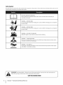 6
6
-
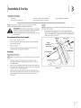 7
7
-
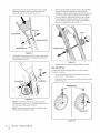 8
8
-
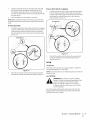 9
9
-
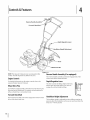 10
10
-
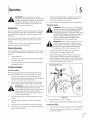 11
11
-
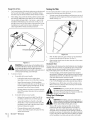 12
12
-
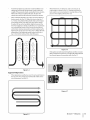 13
13
-
 14
14
-
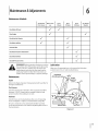 15
15
-
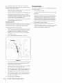 16
16
-
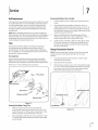 17
17
-
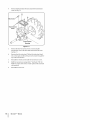 18
18
-
 19
19
-
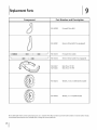 20
20
-
 21
21
-
 22
22
-
 23
23
-
 24
24
-
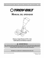 25
25
-
 26
26
-
 27
27
-
 28
28
-
 29
29
-
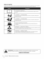 30
30
-
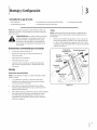 31
31
-
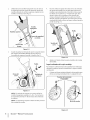 32
32
-
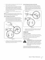 33
33
-
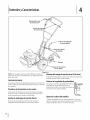 34
34
-
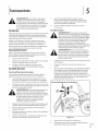 35
35
-
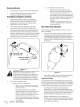 36
36
-
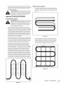 37
37
-
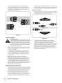 38
38
-
 39
39
-
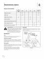 40
40
-
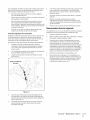 41
41
-
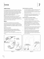 42
42
-
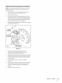 43
43
-
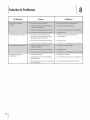 44
44
-
 45
45
-
 46
46
-
 47
47
-
 48
48


ACE 21D-64M1066 El manual del propietario
- Categoría
- Mini cultivadores
- Tipo
- El manual del propietario
- Este manual también es adecuado para
en otros idiomas
- English: ACE 21D-64M1066 Owner's manual
Artículos relacionados
Otros documentos
-
MTD 21AA40M1052 El manual del propietario
-
-
Troy-Bilt 643B Manual de usuario
-
-
Troy-Bilt 21D64M1066 Manual de usuario
-
-
-
-
-