
MANUAL CODE: 14460049
MANUAL VERSION: V1209
LINEAR ENCODER MODEL: SVA
ENCODER LINEAL MODELO: SVA
Fagor Automation

Page 2/16 - "SVA" - V1209
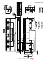
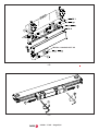
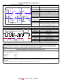
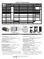
Dimensions in mm
Dimensiones en mm
DISTANCE-CODED I0
INCREMENTAL I0

V1209 - "SVA" - Page 3/16
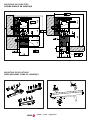
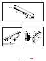
MOUNTING POSSIBILITIES
POSIBILIDADES DE MONTAJE
MOUNTING PRECAUTIONS
PRECAUCIONES PARA EL MONTAJE

Page 4/16 - "SVA" - V1209
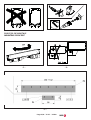
PROCESO DE MONTAJE
MOUNTING PROCESS
- 1 - - 2 -
- 3 -

V1209 - "SVA" - Page 5/16
- 4 -
Washer / Arandela: AET 4.3
- 5 -

Page 6/16 - "SVA" - V1209
- 7 - - 8 -
- 6 -
After mounting it on the machine
Tras montarla en la máquina

V1209 - "SVA" - Page 7/16
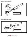
Option. Air intake on the endblock
Opción. Entrada de aire en la regla
Option. Air intake on the reader head
Opción. Entrada de aire en la cabeza
ISO 8573-1
Class 1 - Max. Particle 0.1μ
Class 4 (7 bar) - Dewpoint / Punto rocío 3ºC
Class 1 - Max. Oil concentration: 0.01 mg/m
3
Quitar cierre / Remove lock screw: Allen SW 1.5
ISO 8573-1
Class 1 - Max. Particle 0.1μ
Class 4 (7 bar) - Dewpoint / Punto rocío 3ºC
Class 1 - Max. Oil concentration: 0.01 mg/m
3

Page 8/16 - "SVA" - V1209
ELECTRICAL CHARACTERISTICS
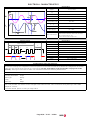
1 Vpp incremental signals
Signals A, B, /A & /B
V
A
pp
1V +20%, -40%
V
B
pp
1V +20%, -40%
DC offset 2.5V
0.5V
Signal period 20
m
Phase Shift A & B 90º
10%
V
A
/
V
B
0.8V to 1.25V
Freq@120m/min 100kHz
Power supply V 5V
10%,
Power supply Imax 250mA (no load) (sense possible)
Max cable length
150 meters. For lengths over 9 meters, a 1m
cable and an extension cable must be used
whose characteristics are:
(4x2x0.14+4x0.5+(4x0.14)) mm2
Absolute signals
Transmission SSI synchronous serial data transfer via RS 485
Levels EIA RS 485
Clock frequency 100kHz - 500kHz
Max bits (n) 32 (configurable)
T1
s to 10
s
t
1
> 1
s
t
2
20
s to 35
s
SSI Grey or binary (configurable)
Parity Fully configurable
Specification
Specification
V
A
V
B
90º
20
m
1V
pp
1V
pp
T
MSB LSB
1 2 3 n-1
n
t
1
t
2
Clock sequence
Number of Bits 32
Counting Resolution 0.1µm
Data Type Binary
Parity NO
Time Out 450µs
Normally it is possible to match these values by adjusting them in the unit the linear encoder is connected to. However, if
this is not possible, the values can be changed in the linear encoder. This can be done using the Fagor PD-U-ENC
adapter to connect
For further details please consult you Fagor office.
To function correctly the configuration of the SSI protocol in the linear encoder must match the configuration of the SSI
protocol in the unit the linear encoder is connected to (see the description of the parameters on page 10 of this
manual). The Fagor SVA linear encoders are manufactured with the following default values.
Default values for SSI protocol in Fagor linear encoders (scales)
Configuration of the SSI protocol

V1209 - "SVA" - Page 9/16
CARACTERISTICAS ELECTRICAS
Señales 1 Vpp incrementales
Señales A, B, /A & /B
V
A
pp
1V +20%, -40%
V
B
pp
1V +20%, -40%
DC offset 2.5V
0.5V
Período de señal 20
m
Desfase A & B 90º
10%
V
A
/
V
B
0.8V to 1.25V
Frec. @120m/min 100kHz
Alimentación V 5V
10%,
Imáx de
alimentación
250mA (sin carga) (sense posible)
Máx. longitud cable
150 metros. Para longitudes mayores de 9
metros se debe utilizar un cable de 1m y la
alargadera correspondiente con cable de
(4x2x0.14+4x0.5+(4x0.14)) mm2
Señales a bsoluta s
Transmisión SSI transferencia serie síncrona via RS 485
Niveles EIA RS 485
Frecuencia reloj 100kHz - 500kHz
Max bits (n) 32 (configurable)
T1
s a 10
s
t
1
> 1
s
t
2
20
s a 35
s
SSI Grey o binario (configurable)
Paridad Totalmente configurable
Especificaciones
Especificaciones
T
MSB LSB
1 2 3 n-1
n
t
1
t
2
Clock sequence
VA
V
B
90º
20
m
1V
pp
1V
pp
Número de bits 32
Resolución de contaje 0.1µm
Tipo de datos Binario
Paridad NO
Time Out 450µs
Normalmente, estos valores se pueden ajustar en el equipo al que se conecta la regla. Sin embargo, si esto no es posible,
se pueden cambiar los valores en la regla utilizando el adaptador Fagor PD-U-ENC conectándolo a un PC a través del
puerto USB.
Para más información, consulte con la oficina de Fagor Automation más cercana.
Para que funcione correctamente, la configuración del protocolo SSI de la regla debe coincidir con la configuración del
protocolo SSI del equipo al que se conecta la regla
(ver la descripción de los parámetros en la página 11 de este
manual)
. Las reglas SVA de Fagor salen de fábrica los siguientes valores por defecto:
Valores por defecto en reglas Fagor para el protocolo SSI
Configuración del protocolo SSI

Page 10/16 - "SVA" - V1209
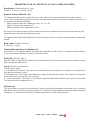
PARAMETERS FOR SSI PROTOCOL IN "SVA" LINEAR ENCODERS
Resolution: (Default value = 0.1μm)
Options: 0.1μm, 1 µm and 10 µm
Number of bits: (Default = 32)
This parameter can only be set to an even value and it is recommended that it only be used as
such. If the system that is going to read the encoder works with a defined odd number of bits then it
is necessary to do the following:
- Add one bit to make the number to even. 23 + 1 = 24
- Select “Transmit the last bit as 0” .
- Adjust the time out to a desirable value
By doing this the transmission will end with the time out condition because the pulses given by the
master are less than needed by the encoder
The appropriate data length depends on the resolution of the encoder and the encoders measuring
length.
Data code: (Default = Binary)
0 = binary, 1 = gray
Transmit the last bit as 0: (Default = 0)
When set to “1” the data output is shifted to the left and the LSB is set to 0 to adjust the data output
to an odd number of pulses. See also “Number of bits”
Parity Bit: (Default = NO)
If parity option is specified the parity bit is sent after the LSB. It must be set to odd or even to comply
with subsequent electronics.
Latch: (Default = continuous)
Three options exist:
1: Calculate continuously: The value is calculated continuously and upon receipt of clock pulses the
last value calculated is sent.
2: Calculate once: The value is calculated on receipt of the last clock pulse. This value is not transmit-
ted until the next clock pulses are received.
3: Timed calculation: The value is calculated a specified time after the first clock pulse is received.
The time period is introduced in μs.
SSI time out
This is the time out value in microseconds. It sets the period of time before a reset will occur should all
data bits not be received during a transmission. The time out value defines the lowest communication
frequency, i.e. maximum time from the beginning to the end of the transmission.

V1209 - "SVA" - Page 11/16
PARÁMETROS PARA EL PROTOCOLO SSI DE LOS ENCODERS LINEALES "SVA"
Resolución: (Valor por defecto = 0.1μm)
Opciones: 0.1μ m, 1 µm y 10 µm
Número de bits: (Por defecto = 32)
Este parámetro sólo puede tener un valor par y se recomienda utilizarlo sólo como tal. Si el siste-
ma al que se va a conectar el encoder funciona con un número de bits impar, será necesario hacer
lo siguiente:
- Añadir un bit para que el número sea par. 23 + 1 = 24
- Seleccionar “Transmitir el último bit como 0”.
- Ajustar el “time-out” a un valor deseable
Al hacer esto, la transmisión finalizará con la condición de “time-out” porque los impulsos propor-
cionados por el master son menos que los que el encoder necesita.
La longitud de datos correcta depende de la resolución de la regla y el curso de medición de las
reglas.
Código de datos: (Por defecto = binario)
0 = binario, 1 = gray
Transmitir el último bit como 0: (Por defecto = 0)
Cuando se pone a “1”, la salida de datos se desplaza a la izquierda y el bit menos significativo
(LSB) se pone a 0 para ajustar la salida de datos a un número impar de impulsos. Ver también
“Número de bits”
Bit de paridad: (Por defecto = NO)
Si se indica la opción de paridad, el bit de paridad se envía después del bit menos significativo
(LSB). Debe fijarse como impar para coincidir con el equipo al que se conecte la regla.
Anclaje (Latch): (Por defecto = continuo)
Hay tres opciones:
1: Calcular continuamente: El valor se calcula continuamente y se envía el último valor calculado al
recibir los impulsos de reloj.
2: Calcular una vez: El valor se calcula al recibir el último impulso de reloj. El valor no se transmite
hasta que se reciban los siguientes impulsos de reloj.
3: Cálculo temporizado: El valor se calcula después de un período de tiempo determinado tras
recibir el primer impulso de reloj. El período de tiempo se introduce en μs.
“Time-out” de SSI
Es el valor de “time-out” en microsegundos. Fija el período de tiempo antes de que se produzca un
reset si no se reciben todos los bits durante una transmisión. El valor de “time-out” define la mínima
frecuencia de comunicación; o sea: el máximo tiempo desde el comienzo hasta el final de la transmi-
sión.

Page 12/16 - "SVA" - V1209
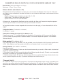
EXTENSION CABLES / ALARGADERAS
Extension Cable
Alargadera
Connector C8 C9 C8 SubD-15HD-M
COLOR CABLE COLOR CABLE
[(4x0,14mm2)+2x
4x0,14mm2+4x0,
5mm2]
[(4x0,14mm2)+2x
4x0,14mm2+4x0,
5mm2]
Verde/Negro Verde/Negro
Green/Black Green/Black
Amarillo/Negro Amarillo/Negro
Yellow/Black Yellow/Black
Azul/Negro Azul/Negro
Blue/Black Blue/Black
Rojo/Negro Rojo/Negro
Red/Black Red/Black
DATA 14 Gris / Gray 14 14 Gris / Gray 5
/DATA 17 Rosa / Pink 17 17 Rosa / Pink 6
CLOCK 8 Violeta / Purple 8 8 Violeta / Purple 7
/CLOCK 9 Amarillo/Yellow 9 9 Amarillo/Yellow 8
Marrón/Verde Marrón/Verde
Brown/Green Brown/Green
+5V_SENSE 1 Azul / blue 1 1 Azul / blue 10
Blanco/Verde Blanco/Verde
White/Green White/Green
GND_SENSE 4 Blanco/White 4 4 Blanco/White 12
13
14
Internal SHIELD 11 Int Shield 11 11 Int Shield 15
CARCASA PANTALLA
HOUSING SHIELD
PANTALLA
SHIELD
CARCASA
HOUSING
3
4
9
11
7
10
15
16
12
13
7
10
12
13
7
10
B
+5V
GND
External SHIELD
PINSIGNAL / SEÑAL
A
/A
15
16
1
2
XC-C8-xF-C9 XC-C8-xF-D
/B
15
16
12
13
PIN PIN PIN
* 150 m grantizando que la Vcc en el captador sea
5V ±10%.
* 150 m guaranteeing that the Vdc of the linear
encoder remains at 5V ±10%.
TOTAL LENGTH
Reference Connector Connector Reference Connector LONGITUD TOTAL
EC-xPA-DA
EC-xPA-DA-N
EC-xB-D
EC-xB-D-N
EC-xB-C9 C9 C8 XC-C8-xF-D SubD-15 HD-M
EC-xB-C9-N Round 17-PM/RM Round 17-PH/RH XC-C8-xF-C9 C9 - Round 17-PM/RM
EC-xB-O
EC-xB-O-N
PM = Pines macho, RM= Rosca macho, PH= Pines hembra, RH = Rosca hembra, M = Macho, H = Hembra
Round = Circular, PM = Male pins, RM= Male thread, PH= Female pins, RH = Female thread, M = Male, H = Female
CABLE EXTENSION CABLE / ALARGADERA
No connector 9 m
SubD-15 HD-M
* 150 m
9 m

V1209 - "SVA" - Page 13/16
CARACTERISTICAS MECANICAS
Velocidad máxima: 120 m/min
60 m/min para 1µm de resolución
Vibración máxima (55 a 2000 Hz): 200 m/s² (20g)
Shock (11 ms): 300 m/s
2
(30g)
Fuerza de desplazamiento: < 4 N
Estanqueidad: IP53
Si se utiliza un dispositivo de entrada de aire la es-
tanqueidad es IP64 (DIN 40050)
Temperatura de trabajo: 0 ... 50°C
Temperatura almacenamiento -20° ... +70°C
Humedad relativa: 20 ... 80%
Peso (guía incluida): 0.25kg + 1.55kg/m
Escala: Vidrio grabado con un periodo 20 µm
Radio de curvatura del cable: > 75 mm
Referencia absoluta:
La posición de referencia entre cabeza y regla se
determina sin necesidad de realizar ningún
movimiento. El controlador puede solicitar en
cualquier momento la posición de la regla.
MECHANICAL CHARACTERISTICS
Maximum speed: 120 m/min
60 m/min for 1µm resolution
Maximum vibration (55 to 2000 Hz): 200 m/s² (20g)
Shock (11 ms): 300 m/s
2
(30g)
Moving force: < 4 N
Sealing protection: IP53
When using an air inlet: IP64 (DIN 40050)
Working temperature: 0°C .. 50°C(32°F .. 122°F)
Storage temperature: -20°C ..+70°C (-4°F.. 158°F)
Relative Humidity: 20 ... 80%
Weight (guide included): 0.25kg + 1.55kg/m
Scale: 20 µm-pitch graduated glass.
Cable bending radius: > 75 mm
Absolute reference:
The reference position beteween the reader head and
the linear encoder is determined without having to
move the axis. The CNC can request the position of
the linear encoder at any time.
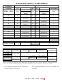
EC-B-D EC-B-C9 EC-B-0
SEÑAL SUBD-15HD (M) ROUND / CIRCULAR 17 (M) -
SIGNAL COLOR (mm2) PIN PIN PIN PIN COLOR mm2
A
Verde/Green 1 15 - 1
/A
A
marillo/Yellow 2 16 - 2
B
A
zul/Blue 3 12 - 3
/B Ro
j
o/Red 4 13 - 4
DATA Gris/Gra
y
5 14 - 5 Verde/Green
/DATA Rosa/Pink 6 17 - 6
A
marillo/Yellow
CLOCK Ne
g
ro/Black 7 8 - 7
A
zul/Blue
/CLOCK Violeta/Pur
p
le 8 9 - 8 Ro
j
o/Red
+5V Marrón/Brown 9 7 - 9 Marrón/Brown
Rojo-Azul /
Verde-claro
-Gris/Gray
Red-Blue / Li
g
ht
green
-
0V Blanco/White 11 10 - 11 Blanco/White
Gris-Rosa /
Naran
j
a
-
Grey-Pink /
Oran
g
e
-
13 - 13
14 - 14
GND Int. Shield 15 Int Shield Internal SHIELD
CARCASA PANTALLA CARCASA PANTALLA
HOUSING SHIELD HOUSING SHIELD
External SHIELD
CABLE [4x2x0,14mm2]
1
4
CABLE [(4x0,08mm2)+4x0,08mm2+4x0,14mm2]
0.08
0.14
12
EC-PA-DA
SUBD-15HD (M)
0V_SENSE
+5V_SENSE 10
0.14
Rosa/Pink12
10
REF. / Name :
Connector:
C9 = terminales macho, rosca machoC9 = male pins, male thread
CABLES / MANGUERAS
Front view
10.4
SUB-D 15 HD (M)
19
25
38
53
31

Page 14/16 - "SVA" - V1209
Mondragón a 1 de Septiembre de 2009Mondragón September 1st 2009
The information described in this manual may be
subject to variations due to technical modifications.
FAGOR AUTOMATION, S. Coop. Ltda. reserves the
right to modify the contents of this manual without
prior notice.
* Term: 12 months from factory invoice date.
* It covers parts and labor at FAGOR AUTOMATION.
* Travel expenses are payable by the customer.
* Damages due to causes external to FAGOR
AUTOMATION, such as unauthorized manipulation,
blows, etc. are not covered.
WARRANTY
La información descrita en este manual puede estar
sujeta a variaciones motivadas por modificaciones
técnicas.
FAGOR AUTOMATION S. Coop. Ltda. se reserva el
derecho de modificar su contenido, no estando
obligada a notificar las variaciones.
* 12 meses desde fecha de expedición de fábrica.
* Cubre gastos de Materiales y Mano de Obra de repa-
ración en FAGOR AUTOMATION.
* Gastos de desplazamiento a cargo del cliente.
* No cubre averías por causas ajenas a FAGOR
AUTOMATION, como: golpes, manipulación por per-
sonal no autorizado, etc.
GARANTIA
DECLARATION OF CONFORMITY
Manufacturer: Fagor Automation, S. Coop.
Barrio de San Andrés s/n, C.P. 20500, Mondragón -
Guipúzcoa- (SPAIN)
We declare under our exclusive responsibility the
conformity of the product referred to in this manual.
Note. Some additional characters may follow the model
references indicated in this manual. They all comply with
the following regulations:
ELECTROMAGNETIC COMPATIBILITY:
EN 61000-6-2:2005 Standard on immunity in industrial
environments
EN 61000-6-4:2007 Standard on emission in industrial
environments
According to the European Directive:
2004/108/CE on electromagnetic compatibility.
DECLARACION DE CONFORMIDAD
Fabricante: Fagor Automation, S. Coop.
Barrio de San Andrés s/n, C.P. 20500, Mondragón -
Guipúzcoa- (ESPAÑA)
Declaramos bajo nuestra exclusiva responsabilidad la
conformidad del producto al que hace referencia este
manual
Nota. Algunos caracteres adicionales pueden seguir a
las referencias de los modelos indicados en este manual.
Todos ellos cumplen con las siguientes normas:
COMPATIBILIDAD ELECTROMAGNÉTICA:
EN 61000-6-2:2005 Norma de Inmunidad en entornos
industriales
EN 61000-6-4:2007 Norma de Emisión en entornos
industriales
De acuerdo con las disposiciones de la Directiva
Comunitaria:
2004/108/CE de Compatibilidad Electromagnética.

V1209 - "SVA" - Page 15/16

Fagor Automation S. Coop.
Bº San Andrés Nº19
Apdo Correos 144
20500 - Arrasate/Mondragón
- Spain -
Web: www.fagorautomation.com
Email: [email protected]
Tel.: (34) 943 719200
Fax: (34) 943 791712
-
 1
1
-
 2
2
-
 3
3
-
 4
4
-
 5
5
-
 6
6
-
 7
7
-
 8
8
-
 9
9
-
 10
10
-
 11
11
-
 12
12
-
 13
13
-
 14
14
-
 15
15
-
 16
16


Fagor SVA Series El manual del propietario
- Tipo
- El manual del propietario
- Este manual también es adecuado para
en otros idiomas
- English: Fagor SVA Series Owner's manual
Artículos relacionados
-
Fagor SVA Series El manual del propietario
-
-
-
Fagor HA-D200 Series El manual del propietario
-
Fagor MM/MM2 Series El manual del propietario
-
-
-
-
-
Fagor GA Series El manual del propietario