Air King 4TM61C Manual de usuario
- Categoría
- Ventiladores domésticos
- Tipo
- Manual de usuario
Este manual también es adecuado para

READ AND SAVE THESE INSTRUCTIONS
READ CAREFULLY BEFORE ATTEMPTING TO ASSEMBLE, INSTALL, OPERATE OR MAINTAIN THE PRODUCT DESCRIBED. PROTECT
YOURSELF AND OTHERS BY OBSERVING ALL SAFETY INFORMATION. FAILURE TO COMPLY WITH
INSTRUCTIONS COULD RESULT IN PERSONAL INJURY AND/OR PROPERTY DAMAGE!
RETAIN INSTRUCTIONS FOR FUTURE REFERENCE.
1
2084796Rev. E 4/01
20" WALLMOUNT FAN
20" (50.8 cm) MODEL 4TM61C/9020C
OPERATING INSTRUCTIONS & PARTS MANUAL
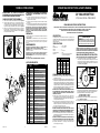
DESCRIPTION
The AirKing 20" (50.8 cm) wallmount fan features 3-speed pull cord
operation and a 3-paddle fan blade. This fan has a permanently lubricated
motor with a 9 ft. (2.74 m) 18/3 cord set and is constructed of sturdy,
powder coated steel.
SPECIFICATIONS
Motor.......................................120V, 50/60 Hz
Blade diameter .......................20" (50.8 cm)
Speeds....................................3
Control ....................................Pull Cord
Air flow distribution .................360°
Approvals................................UL Listed. Close mesh fan guard
................................................
meets OSHA requirements.
WARNING: BECAUSE OF SIZE AND WEIGHT OF THIS FAN, MAKE
SURE ALL PARTS ARE COMPLETELY ASSEMBLED ACCORDING TO
INSTRUCTIONS. FAILURE TO DO SO COULD RESULT IN FAN COMING
APART DURING OPERATION AND/OR PERSONAL INJURY.
WALL/CEILING BRACKET INSTALLATION
NOTE: ALWAYS INSTALL THE BRACKET TO A MINIMUM OF 2 X 4 STUDDING.
1. Lay Fan Head on flat surface, so the front side is facing down.
Loosely attach one Grill Knob and one Rubber Spacer to the Head
Assembly. Attach the other Grill Knob and Rubber Spacer to the
Head Assembly and FIRMLY tighten. Return to the first Grill Knob
and FIRMLY tighten. (Figure 1)
GENERAL SAFETY INFORMATION
1. Make certain that the power source conforms to the electrical
requirements of the fan.
2. The power cord is equipped with a three-prong grounded plug that must
be inserted into a matching receptacle. Under no circumstances must the
grounding prong be cut off the plug. Where a two-prong wall receptacle
is encountered, it must be replaced with a properly grounded three-prong
receptacle installed in accordance with the National Electrical Code
(NEC) and all applicable local codes and ordinances. This work must be
done only by a qualified electrician, using copper wire only.
WARNING: USE OF A THREE-PRONG TO TWO-PRONG ADAPTER IS
NOT RECOMMENDED. IMPROPER CONNECTION MAY CREATE
THE RISK OF ELECTROCUTION. USE OF SUCH ADAPTERS IS NOT
PERMITTED IN CANADA.
3. Where possible, avoid the use of extension cords. If they must be
used, minimize the risk of overheating by ensuring that they are UL
listed and of the proper gage and length. Never use a single extension
cord to operate more than one fan.
4. Do not insert fingers or foreign objects into the fan. Do not block or
tamper with the fan in any manner while it is in operation. Do not touch
the fan while in operation or just after it has been turned off, as some
parts may be hot enough to cause injury.
5. Unplug power cord before installing or servicing the fan.
WARNING: DO NOT DEPEND UPON THE ON-OFF SWITCH AS THE
SOLE MEANS OF DISCONNECTING POWER WHEN INSTALLING OR
SERVICING THE FAN. ALWAYS UNPLUG THE POWER CORD.
6. This fan is intended for general use ONLY. It must NOT be used in
potentially dangerous locations such as flammable, explosive, chemical-
laden or wet atmospheres.
WARNING: TO REDUCE THE RISK OF FIRE OR ELECTRIC SHOCK, DO
NOT USE THIS FAN WITH ANY SOLID STATE SPEED CONTROL DEVICE.
7. DO NOT use fan in a window. Rain may create an electrical hazard.
8. Completely reassemble fan, according to instructions before
reconnecting to power supply.
Figure 2 (Wall Mount Assembly)
Fan Head
Nut
Wall Stud
Figure 3 (Ceiling Mount Assembly)
Fan Head
Bolt
2. Locate the wall or ceiling stud nearest to the desired Fan location.
Following the proper mounting diagram, attach the Bracket to the stud
using three (3) 5/16" diameter x 2" long Lag Screws (Not Supplied) or
appropriately sized Bolts and Nuts if attaching to "I" beams.
Wall Mount Assembly (Figure 2)
Ceiling Mount Assembly (Figure 3)
3. Insert Bolt through Yoke, Bracket, Pivot Hole, Flatwasher, and into
Locknut. (Figure 2) or (Figure 3)
4. While holding Fan in the desired position, firmly tighten the 7/16" Bolt.
Yoke
Bracket
Yoke
Bracket
Flatwasher
Pivot
Hole
Pivot
Hole
Flatwasher
Ceiling Stud
4
2084796Rev. E 4/01
MODELO 4TM61C/9020C
LISTA DE REPUESTOS
Ref No. de
Descripción Cant.
No. Parte
Cable de
Soporte
Secundario
Horqueta
Lazo Firme
en el Cable
Cola de 1"-2"
Figura 4 Figura 5
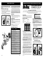
ADVERTENCIA: EL CABLE DE SOPORTE
SECUNDARIO QUE SE PROPORCIONA DEBE SER
USADO PARA SEGURIDAD ADICIONAL.
CABLE DE SOPORTE SECUNDARIO
1. Forme un lazo con el extremo del cable alrededor de la Horqueta. (Figura 5)
2. Coloque una Grapa de Cable con la "U" en la cola del lazo, dejando una
cola de aproximadamente 1 a 2 pulgadas. Apriete las tuercas de la grapa
a un esfuerzo de torsión de 32 pulgadas-libra, formando un lazo firme.
Asegúrese que ninguna parte del cable interfiera con la hélice. (Figura 5)
3. Envuelva el otro extremo del cable alrededor de una viga o armadura
segura del edificio, o de otro soporte cerca del Ventilador. Si ninguno de
ellos está disponible, envuelva el cable alrededor de la ménsula. (Figura 4)
Recoja las partes sobrantes del cable.
ADVERTENCIA: USE SOLAMENTE LOS ELEMENTOS
DE MONTAJE RECOMENDADOS PARA ESTE
VENTILADOR.
4. Coloque la Grapa de Cable restante, tal como se indica en el paso 2. El
exceso de la cola debe ser cortado de modo que se extienda 1 a 2
pulgadas más allá de la Grapa.
5. Verifique el conjunto para asegurar que la hélice esté libre de cualquier
obstrucción.
6. Enchufe el cable de conexión eléctrica dentro de un tomacorriente de tres
hojas conectado ampropiadamente a tierra. La unidad está lista para funcionar.
ADVERTENCIA: EL USO DEL CABLE DE SOPORTE SECUNDARIO NO
GARANTIZA LA PROTECCIÓN CONTRA LESIONES PERSONALES; EL
MONTAJE TANTO DEL CIRCULADOR COMO DEL CABLE PODRÍA
FALLAR SI SE LO SOMETE A ABUSOS, NEGLIGENCIA O INSTALACIÓN
NO APROPIADA.
OPERACIÓN
1.Conecte el cable y seleccione la velocidad de funcionamiento deseada con
el cordón accionador.
2. ADVERTENCIA: Este ventilador debe ser usa do solmente en unambiente
limpio y seco. Si producto esta montado de alguna otra manera espec´ifica que
indica la hoja de instrucción, purdiera anularse y no tener valor la garantia del
fabricante
MANTENIMIENTO
ADVERTENCIA: DESCONECTE SIEMPRE EL CORDÓN ANTES DE
INTENTAR REALIZAR CUALQUIER FUNCIÓN DE SERVICIO.
LIMPIEZA: Use un trapo y una solución de jabón suave, tal como detergente
líquido para lavar trastes.
ADVERTENCIA: No use gasolina, bencina, diluyente de pintura ni
limpiadores fuertes en aerosol, ya que éstos dañarán el ventilador.
ALMACENAMIENTO: Cuando no lo utilice, mantenga el aparato en un
lugar limpio y seco.
EL MOTOR HA SIDO PERMANENTEMENTE LUBRICADO.
******* Suministros por Bolso de Piezas Componentes Físicas (5098008)
Nut
Bolt
Commercial Style fan
WARNING:
This fan should be used only in a
clean, dry environment. Mounting of this product
in any way other than specified in the instruction
sheet will null and void the manufacturers warranty.
MODEL
4TM61C/9020C
SPEED
HIGH MED LOW
CFM 7510 5010 3735
M
3
/s 3.54 2.36 1.76
RPM 1560 1041 776
Amps 1.78 1.46 1.02
Watts 207 167 115
dB A 62 55 48
Grill Knob
Rubber Spacer
Rubber Spacer
Grill Knob
Figure 1
Yoke
14
12
11
10
13
8
7
5
6
2
4
3
11
10
18
17
16
15
20
19
21
22
23
25
24
25
24
8
1
9
26
26
1 2065510 Placa de Identificación 1
2 2050015 Cordón Eléctrico 1
3 2010636 Cubierta del Motor (Trasera) 1
4 2055001 Interruptor del Cordón Accionador 1
5 ******* Cordón Accionador con Colgante 1
6 2090552 Tuerca para el Alambre 2
7 5096037A Rejilla Trasera 1
8 2091126B Tornillo de #6 x 5/8 Tipo 25 PTH 3
9 2030021SB Motor 1
10 ******* Perilla de la Rejilla 2
11 ******* Espaciador de Caucho 2
12 2011604 Horqueta 1
13 5082075BK Hélice 1
14 5090044 Tornillo Prisionero de 1/4-28 x 3/8" 1
15 ******* Perno de 7/16" -18 x 5" (Negro) 1
16 ******* Arandelas Planas 7/16" (Negro) 1
17 2060016 Soporte 1
18 5096038A Rejilla Delantera 1
19 2091143 Tornillo de #8 x 3/8 Tipo F PPH 8
20 2070004A Ojo de Buey 1
21 ******* Cable de Seguridad 1
22 ******* Grapa de Cable 2
23 ******* Tuerca de Seguridad 7/16-18 1
24 2091162 Tornillo de #8 x 1/2 Tipo F PPH 4
25 5060016 Placa de Pivote con Hexagonal 2
26 5090045 #10-32 x 1/2 HWH SERR F-ZP 3

MODEL 4TM61C/9020C
2084796Rev. E 4/01
2
Secondary
Support
Cable
Yoke
Tight Loop
In Cable
1" - 2" Tail
Figure 4 Figure 5
CAUTION: THE SECONDARY SUPPORT CABLE
PROVIDED SHOULD BE USED FOR ADDITIONAL
SAFETY.
SECONDARY SUPPORT CABLE
1. Loop one end of cable around the Yoke. (Figure 5)
2. Attach a Cable Clamp with the "U" on the tail side of the loop leaving
a tail approximately 1 to 2 inches. Tighten clamp nuts to 32 inch-
pounds torque forming a tight loop. Make sure no part of the cable
interferes with the blade. (Figure 5)
3. Wrap the other end of the cable around a secure building joist, truss, or
other support near the Fan. If none of these are available wrap cable
around the bracket. (Figure 4) Take up excess slack in the cable.
CAUTION: USE ONLY THE MOUNTING HARDWARE
WHICH IS RECOMMENDED FOR USE ON THIS FAN.
4. Attach the remaining Cable Clamp as indicated in step 2. The excess
tail should be trimmed to extend 1 to 2 inches past the Clamp.
5. Check the assembly to assure the Blade is free of all obstructions.
6. Plug the power cord into a properly grounded three-prong receptacle.
CAUTION: USE OF THE SECONDARY SUPPORT CABLE DOES NOT
GUARANTEE PROTECTION AGAINST INJURY OF PERSONS,
MOUNTING OF BOTH THE CIRCULATOR AND CABLE COULD FAIL IF
SUBJECTED TO ABUSE, NEGLECT OR IMPROPER INSTALLATION.
OPERATION
1.Plug in cord and select desired operating speed with pull cord.
2. WARNING: This fan should be used only in a clean, dry environment.
Mounting of this product in any way other then specified in the instruction
sheet will null and void the manufacturers warranty
.
MAINTENANCE
WARNING: ALWAYS UNPLUG THE CORD BEFORE SERVICING.
CLEANING: Use a soft cloth and a mild soap solution such as liquid dish
washing detergent.
CAUTION: Do not use gasoline, benzine, thinner, harsh cleaners,
etc. which will damage the fan.
Dry all parts with a soft cloth completely before reconnecting to power
supply.
STORAGE: When not in use, keep unit in a clean dry place.
MOTOR IS PERMANENTLY LUBRICATED.
REPLACEMENT PARTS LIST
Key Part No. Description Qty.
******* Supplied in Hardware Bag (5098008)
LEA Y GUARDE ESTAS INSTRUCCIONES
LÉALAS CUIDADOSAMENTE ANTES DE INTENTAR ARMAR, INSTALAR, OPERAR O DAR MANTENIMIENTO AL PRODUCTO DESCRITO.
PROTÉJASE A SÍ MISMO Y A LOS DEMÁS OBSERVANDO TODA LA INFORMACIÓN SOBRE SEGURIDAD. ¡NO SEGUIR LAS INSTRUCCIONES
PODRÍA RESULTAR EN LESIONES PERSONALES Y/O DAÑOS A LA PROPIEDAD!
GUARDE LAS INSTRUCCIONES PARA REFERENCIAS FUTURAS.
INFORMACIÓN GENERAL SOBRE SEGURIDAD
1. Cerciórese de que la fuente de electricidad se adapte a los requerimientos
eléctricos del ventilador.
2. El cordón eléctrico está equipado con una clavija a tierra de tres espigas
que tiene que ser enchufada a un receptáculo del mismo diseño. Bajo
ninguna circunstancia deberá cortarse la espiga a tierra de la clavija. De
existir un receptáculo de pared de dos espigas, deberá reemplazarse por
uno de tres espigas debidamente puesto a tierra e instalado de conformidad
con el Código Nacional de Electricidad y todos los códigos y ordenanzas
locales aplicables. El trabajo deberá hacerlo un electricista calificado,
utilizando exclusivamente alambre de cobre.
ADVERTENCIA: NO SE RECOMIENDA EL USO DE UN ADAPTADOR DE
TRES A DOS ESPIGAS. LA CONEXIÓN INDEBIDA PODRÍA CREAR EL
RIESGO DE SER ELECTROCUTADO. EL USO DE TALES ADAPTADORES
NO ESTÁ PERMITIDO EN CANADÁ.
3. Siempre que sea posible, evite el uso de extensiones eléctricas. Si tienen
que usarse, minimice el riesgo de sobrecalentamiento asegurándose de
que sean de catalogación UL y del calibre y la longitud adecuadas. Nunca
use una sola extensión para operar más de un ventilador.
4. No introduzca los dedos ni objetos extraños en el ventilador. No obstruya
ni manipule indebidamente el ventilador mientras esté en operación. No
toque el ventilador mientras esté en operación ni inmediatamente después
de haberlo apagado, ya que ciertas partes podrían estar lo suficientemente
calientes como para causar una lesión.
5. Desenchufe el cordón eléctrico antes de instalar o dar servicio al ventilador.
ADVERTENCIA: NO DEPENDA DEL INTERRUPTOR DE ENCENDIDO Y
APAGADO COMO EL ÚNICO MEDIO PARA INTERRUMPIR LA
ALIMENTACIÓN ELÉCTRICA CUANDO INSTALE O DÉ SERVICIO AL
VENTILADOR. SIEMPRE DESENCHUFE EL CORDÓN ELÉCTRICO.
6. Este ventilador es para uso general EXCLUSIVAMENTE. NO deberá
usarse en localidades potencialmente peligrosas tales como atmósferas
inflamables, explosivas, cargadas de gases o húmedas.
ADVERTENCIA: PARA REDUCIR EL RIESGO DE INCENDIOS O
DESCARGAS ELÉCTRICAS, NO USE ESTE VENTILADOR CON NINGÚN
DISPOSITIVO DE CONTROL DE VELOCIDAD DE ESTADO SÓLIDO.
7. NO utilice el ventilador en una ventana, ya que la lluvia podría crear un
peligro eléctrico.
8. Vuelva a armar completamente el ventilador, de acuerdo con las
instrucciones, antes de volver a conectarlo a la alimentación eléctrica.
3
MANUAL DE INSTRUCCIONES DE OPERACIÓN Y PARTES
2084796
ADVERTENCIA: DEBIDO AL TAMANO Y PESO DE ESTE VENTILADOR,
ASEGURESE DE QUE TODAS LAS PIEZAS ESTAN COMPLETAMENTE
MONTADAS DE ACUERDO CON LAS INSTRUCCIONES. UN FALLO
PODRIA CAUSAR LA DESUNION DE LAS PIEZAS DURANTE SU
FUNCIONAMIENTO Y/O DANOS PERSONALES.
INSTALACIÓN DE MÉNSULA EN PAREDES / TECHOS
NOTA: SIEMPRE INSTALE LA MÉNSULA EN MONTANTES DE 2X4
COMO MÍNIMO.
1. Ponga la Cabeza del Ventilador sobre una superficie plana de modo que
el frente esté hacia abajo. Coloque en forma aflojada una Perilla de la
Rejilla y un Espaciador de Caucho en el Conjunto de la Cabeza. Coloque
la otra Perilla de la Rejilla y el Espaciador de Caucho en el Conjunto de
la Cabeza y apriete FIRMEMENTE. Vuelva a la primera Perilla de la Rejilla
y apriete FIRMEMENTE. (Figura 1)
El VENTILADOR DE MONTAJE
EN PARED DE 20" (50.8 cm)
20" (50.8 cm) MODELO 4TM61C/9020C
DESCRIPCIÓN
El ventilador montaje en pared AirKing 20" (50.8 cm) ofrece una operación de
accionado por un cordón de 3 velocidades y 3 paletas de ventilador. Este
ventilador dispone de un motor de lubricación permanente con un cordón18/3
de 2.74 cm (9 pies) y está construido con acero pulverizado muy resistente.
ESPECIFICACIONES
Motor...................................................120V, 50/60Hz
Tarmano De Paletas ..........................20" (50.8 cm)
Velocidades ........................................3
Control ................................................Conjuntor rotatorio
Distribución del lujo de aire................360°
Aprobaciones................ Catalogación UL. El protector de malla cerrada
del ventilador satisface las normas OSHA.
2. Localice el montante de pared o techo más cercano a la ubicación
deseada para el Ventilador. Siguiendo el diagrama de montaje apropiado,
una la Ménsula al montante, usando tres (3) Tornillos de Retraso de 5/16"
de diámetro x 2" de longitud (no proporcionados) o Pernos y Tuercas de
tamaño apropiado si se lo monta a vigas "I".
Conjunto de Montaje en la Pared (Figura 2)
Conjunto de Montaje en el Techo (Figura 3)
3. Inserte el Perno a través de la Horqueta, Soporte, Orificio de Giro,
Arandela Plana, y dentro de la Tuerca. (Figura 2) o (Figura 3)
4. Mientras sostiene el Ventilador en la posición deseada, apriete firmemente
el perno de 7/16".
Figura 2
(Conjunto de Montaje en la Pared)
Montante de
Techo
Cabeza
de
Ventilador
Perno
Montante
de Pared
Figura 3
(Conjunto de Montaje en la Pared)
Soporte
Horqueta
Soporte
Arandela
Plana
Orificio
de Giro
Orificio
de Giro
Cabeza
de
Ventilador
Horqueta
Perno Arandela
Plana
Tuerca
Tuerca
MODELO
4TM61C/9020C
VELOC.
ALTA MEDIA BAJA
CFM 7510 5010 3735
M
3
/s 3.54 2.36 1.76
RPM 1560 1041 776
Amps 1.78 1.46 1.02
Watts 207 167 115
dB A 62 55 48
Ventilador Estilo Comercial
ADVERTENCIA: Este ventilador debe ser usa
do solamente en un ambiente limpio y seco. Si
producto esta montado de alguna otra manera
espec´ifica que indica la hoja de instrucción, purdiera
anularse y no tener valor la garantia del fabricante.
Perilla de
la Rejilla
Espaciador
de Caucho
Figura 1
Horqueta
Perilla de
la Rejilla
Espaciador
de Caucho
Rev. E 4/01
14
12
11
10
13
8
7
5
6
2
4
3
11
10
18
17
16
15
20
19
21
22
23
25
24
25
24
8
1
9
26
26
1 2065510 Name Plate 1
2 2050015 Cordset 1
3 2010636 Rear Motor Cover 1
4 2055001 Pull Cord Switch 1
5 ******* Pull Cord with Pendent 1
6 2090552 Wire Nut 2
7 5096037A Rear Grill 1
8 2091126B Screw #6 x 5/8 Type 25 PTH 3
9 2030021SB Motor 1
10 ******* Grill Knob 2
11 ******* Rubber Spacer 2
12 2011604 Yoke 1
13 5082075BK Blade 1
14 5090044 Set Screw 1/4-28 x 3/8" 1
15 ******* Bolt 7/16" -18 x 5" Black 1
16 ******* Flatwasher 7/16" Black 1
17 2060016 Bracket 1
18 5096038A Front Grill 1
19 2091143 Screw #8 x 3/8 Type F PPH 8
20 2070004A Bullseye 1
21 ******* Safety Chain 1
22 ******* Cable Chain Lock 2
23 ******* Locknut 7/16-18 1
24 2091162 Screw #8 x 1/2 Type F PPH 4
25 5060016 Pivot Plate w/Hex 2
26 5090045 #10-32 x 1/2 HWH SERR F-ZP 3
Transcripción de documentos
OPERATING INSTRUCTIONS & PARTS MANUAL MODELO 4TM61C/9020C ADVERTENCIA: USE SOLAMENTE LOS ELEMENTOS DE MONTAJE RECOMENDADOS PARA ESTE VENTILADOR. 4. Coloque la Grapa de Cable restante, tal como se indica en el paso 2. El exceso de la cola debe ser cortado de modo que se extienda 1 a 2 pulgadas más allá de la Grapa. 5. Verifique el conjunto para asegurar que la hélice esté libre de cualquier obstrucción. 6. Enchufe el cable de conexión eléctrica dentro de un tomacorriente de tres hojas conectado ampropiadamente a tierra. La unidad está lista para funcionar. ADVERTENCIA: EL USO DEL CABLE DE SOPORTE SECUNDARIO NO GARANTIZA LA PROTECCIÓN CONTRA LESIONES PERSONALES; EL MONTAJE TANTO DEL CIRCULADOR COMO DEL CABLE PODRÍA FALLAR SI SE LO SOMETE A ABUSOS, NEGLIGENCIA O INSTALACIÓN NO APROPIADA. CABLE DE SOPORTE SECUNDARIO 1. Forme un lazo con el extremo del cable alrededor de la Horqueta. (Figura 5) 2. Coloque una Grapa de Cable con la "U" en la cola del lazo, dejando una cola de aproximadamente 1 a 2 pulgadas. Apriete las tuercas de la grapa a un esfuerzo de torsión de 32 pulgadas-libra, formando un lazo firme. Asegúrese que ninguna parte del cable interfiera con la hélice. (Figura 5) 3. Envuelva el otro extremo del cable alrededor de una viga o armadura segura del edificio, o de otro soporte cerca del Ventilador. Si ninguno de ellos está disponible, envuelva el cable alrededor de la ménsula. (Figura 4) Recoja las partes sobrantes del cable. OPERACIÓN Figura 4 1.Conecte el cable y seleccione la velocidad de funcionamiento deseada con el cordón accionador. 2. ADVERTENCIA: Este ventilador debe ser usa do solmente en unambiente limpio y seco. Si producto esta montado de alguna otra manera espec´ifica que indica la hoja de instrucción, purdiera anularse y no tener valor la garantia del fabricante Figura 5 Cola de 1"-2" Cable de Soporte Secundario Lazo Firme en el Cable MANTENIMIENTO ADVERTENCIA: DESCONECTE SIEMPRE EL CORDÓN ANTES DE INTENTAR REALIZAR CUALQUIER FUNCIÓN DE SERVICIO. LIMPIEZA: Use un trapo y una solución de jabón suave, tal como detergente líquido para lavar trastes. ADVERTENCIA: No use gasolina, bencina, diluyente de pintura ni limpiadores fuertes en aerosol, ya que éstos dañarán el ventilador. ALMACENAMIENTO: Cuando no lo utilice, mantenga el aparato en un lugar limpio y seco. EL MOTOR HA SIDO PERMANENTEMENTE LUBRICADO. Horqueta 20" WALLMOUNT FAN 20" (50.8 cm) MODEL 4TM61C/9020C READ AND SAVE THESE INSTRUCTIONS READ CAREFULLY BEFORE ATTEMPTING TO ASSEMBLE, INSTALL, OPERATE OR MAINTAIN THE PRODUCT DESCRIBED. PROTECT YOURSELF AND OTHERS BY OBSERVING ALL SAFETY INFORMATION. FAILURE TO COMPLY WITH INSTRUCTIONS COULD RESULT IN PERSONAL INJURY AND/OR PROPERTY DAMAGE! RETAIN INSTRUCTIONS FOR FUTURE REFERENCE. DESCRIPTION 23 21 16 17 12 22 15 10 26 24 25 19 11 18 14 11 9 8 26 13 24 4 3 10 MODEL 25 8 1 7 6 2 5 4 HIGH MED LOW CFM M3/s RPM Amps Watts dB A 7510 3.54 1560 1.78 207 62 5010 2.36 1041 1.46 167 55 3735 1.76 776 1.02 115 48 1 2065510 Placa de Identificación 1 2 2050015 Cordón Eléctrico 1 3 2010636 Cubierta del Motor (Trasera) 1 4 2055001 Interruptor del Cordón Accionador 1 GENERAL SAFETY INFORMATION 5 ******* Cordón Accionador con Colgante 1 6 2090552 Tuerca para el Alambre 2 7 5096037A Rejilla Trasera 1 8 2091126B Tornillo de #6 x 5/8 Tipo 25 PTH 3 9 2030021SB Motor 1 10 ******* Perilla de la Rejilla 2 11 ******* Espaciador de Caucho 2 Horqueta 1 1. Make certain that the power source conforms to the electrical requirements of the fan. 2. The power cord is equipped with a three-prong grounded plug that must be inserted into a matching receptacle. Under no circumstances must the grounding prong be cut off the plug. Where a two-prong wall receptacle is encountered, it must be replaced with a properly grounded three-prong receptacle installed in accordance with the National Electrical Code (NEC) and all applicable local codes and ordinances. This work must be done only by a qualified electrician, using copper wire only. WARNING: USE OF A THREE-PRONG TO TWO-PRONG ADAPTER IS NOT RECOMMENDED. IMPROPER CONNECTION MAY CREATE THE RISK OF ELECTROCUTION. USE OF SUCH ADAPTERS IS NOT PERMITTED IN CANADA. 3. Where possible, avoid the use of extension cords. If they must be used, minimize the risk of overheating by ensuring that they are UL listed and of the proper gage and length. Never use a single extension cord to operate more than one fan. 4. Do not insert fingers or foreign objects into the fan. Do not block or tamper with the fan in any manner while it is in operation. Do not touch the fan while in operation or just after it has been turned off, as some parts may be hot enough to cause injury. 5. Unplug power cord before installing or servicing the fan. WARNING: DO NOT DEPEND UPON THE ON-OFF SWITCH AS THE SOLE MEANS OF DISCONNECTING POWER WHEN INSTALLING OR SERVICING THE FAN. ALWAYS UNPLUG THE POWER CORD. 6. This fan is intended for general use ONLY. It must NOT be used in potentially dangerous locations such as flammable, explosive, chemicalladen or wet atmospheres. WARNING: TO REDUCE THE RISK OF FIRE OR ELECTRIC SHOCK, DO NOT USE THIS FAN WITH ANY SOLID STATE SPEED CONTROL DEVICE. 7. DO NOT use fan in a window. Rain may create an electrical hazard. 8. Completely reassemble fan, according to instructions before reconnecting to power supply. 2011604 5082075BK 14 5090044 15 ******* Perno de 7/16" -18 x 5" (Negro) 1 16 ******* Arandelas Planas 7/16" (Negro) 1 17 2060016 18 5096038A 19 2091143 20 2070004A 21 22 Hélice 1 Tornillo Prisionero de 1/4-28 x 3/8" 1 Soporte 1 Rejilla Delantera 1 Tornillo de #8 x 3/8 Tipo F PPH 8 Ojo de Buey 1 ******* Cable de Seguridad 1 ******* Grapa de Cable 2 23 ******* Tuerca de Seguridad 7/16-18 1 24 2091162 Tornillo de #8 x 1/2 Tipo F PPH 4 25 5060016 Placa de Pivote con Hexagonal 2 26 5090045 #10-32 x 1/2 HWH SERR F-ZP 3 ******* Suministros por Bolso de Piezas Componentes Físicas (5098008) Rev. E 4/01 SPEED Descripción Cant. 2084796 Rev. E 4/01 WARNING: BECAUSE OF SIZE AND WEIGHT OF THIS FAN, MAKE SURE ALL PARTS ARE COMPLETELY ASSEMBLED ACCORDING TO INSTRUCTIONS. FAILURE TO DO SO COULD RESULT IN FAN COMING APART DURING OPERATION AND/OR PERSONAL INJURY. WALL/CEILING BRACKET INSTALLATION NOTE: ALWAYS INSTALL THE BRACKET TO A MINIMUM OF 2 X 4 STUDDING. 1. Lay Fan Head on flat surface, so the front side is facing down. Loosely attach one Grill Knob and one Rubber Spacer to the Head Assembly. Attach the other Grill Knob and Rubber Spacer to the Head Assembly and FIRMLY tighten. Return to the first Grill Knob and FIRMLY tighten. (Figure 1) 4TM61C/9020C No. de Parte 13 clean, dry environment. Mounting of this product in any way other than specified in the instruction sheet will null and void the manufacturers warranty. Motor ....................................... 120V, 50/60 Hz Blade diameter ....................... 20" (50.8 cm) Speeds .................................... 3 Control .................................... Pull Cord Air flow distribution ................. 360° Approvals ................................ UL Listed. Close mesh fan guard ................................................ meets OSHA requirements. Ref No. 12 WARNING: This fan should be used only in a SPECIFICATIONS LISTA DE REPUESTOS 20 Commercial Style fan The AirKing 20" (50.8 cm) wallmount fan features 3-speed pull cord operation and a 3-paddle fan blade. This fan has a permanently lubricated motor with a 9 ft. (2.74 m) 18/3 cord set and is constructed of sturdy, powder coated steel. Yoke Grill Knob Grill Knob Rubber Spacer Rubber Spacer Figure 1 2. Locate the wall or ceiling stud nearest to the desired Fan location. Following the proper mounting diagram, attach the Bracket to the stud using three (3) 5/16" diameter x 2" long Lag Screws (Not Supplied) or appropriately sized Bolts and Nuts if attaching to "I" beams. Wall Mount Assembly (Figure 2) Ceiling Mount Assembly (Figure 3) 3. Insert Bolt through Yoke, Bracket, Pivot Hole, Flatwasher, and into Locknut. (Figure 2) or (Figure 3) 4. While holding Fan in the desired position, firmly tighten the 7/16" Bolt. Figure 2 (Wall Mount Assembly) Nut Bracket Flatwasher Pivot Hole Wall Stud ADVERTENCIA: EL CABLE DE SOPORTE SECUNDARIO QUE SE PROPORCIONA DEBE SER USADO PARA SEGURIDAD ADICIONAL. Bolt Figure 3 (Ceiling Mount Assembly) Ceiling Stud Nut Bracket Pivot Hole Bolt Flatwasher Yoke Yoke Fan Head 1 Fan Head 2084796 MANUAL DE INSTRUCCIONES DE OPERACIÓN Y PARTES MODEL 4TM61C/9020C 4. Attach the remaining Cable Clamp as indicated in step 2. The excess tail should be trimmed to extend 1 to 2 inches past the Clamp. 5. Check the assembly to assure the Blade is free of all obstructions. 6. Plug the power cord into a properly grounded three-prong receptacle. CAUTION: USE OF THE SECONDARY SUPPORT CABLE DOES NOT GUARANTEE PROTECTION AGAINST INJURY OF PERSONS, MOUNTING OF BOTH THE CIRCULATOR AND CABLE COULD FAIL IF SUBJECTED TO ABUSE, NEGLECT OR IMPROPER INSTALLATION. SECONDARY SUPPORT CABLE 1. Loop one end of cable around the Yoke. (Figure 5) 2. Attach a Cable Clamp with the "U" on the tail side of the loop leaving a tail approximately 1 to 2 inches. Tighten clamp nuts to 32 inchpounds torque forming a tight loop. Make sure no part of the cable interferes with the blade. (Figure 5) 3. Wrap the other end of the cable around a secure building joist, truss, or other support near the Fan. If none of these are available wrap cable around the bracket. (Figure 4) Take up excess slack in the cable. Figure 4 20" (50.8 cm) MODELO 4TM61C/9020C LEA Y GUARDE ESTAS INSTRUCCIONES LÉALAS CUIDADOSAMENTE ANTES DE INTENTAR ARMAR, INSTALAR, OPERAR O DAR MANTENIMIENTO AL PRODUCTO DESCRITO. PROTÉJASE A SÍ MISMO Y A LOS DEMÁS OBSERVANDO TODA LA INFORMACIÓN SOBRE SEGURIDAD. ¡NO SEGUIR LAS INSTRUCCIONES PODRÍA RESULTAR EN LESIONES PERSONALES Y/O DAÑOS A LA PROPIEDAD! GUARDE LAS INSTRUCCIONES PARA REFERENCIAS FUTURAS. OPERATION Figure 5 1" - 2" Tail Tight Loop In Cable Secondary Support Cable El VENTILADOR DE MONTAJE EN PARED DE 20" (50.8 cm) CAUTION: USE ONLY THE MOUNTING HARDWARE WHICH IS RECOMMENDED FOR USE ON THIS FAN. Ventilador Estilo Comercial DESCRIPCIÓN MAINTENANCE ESPECIFICACIONES WARNING: ALWAYS UNPLUG THE CORD BEFORE SERVICING. CLEANING: Use a soft cloth and a mild soap solution such as liquid dish washing detergent. CAUTION: Do not use gasoline, benzine, thinner, harsh cleaners, etc. which will damage the fan. Dry all parts with a soft cloth completely before reconnecting to power supply. STORAGE: When not in use, keep unit in a clean dry place. MOTOR IS PERMANENTLY LUBRICATED. Yoke Key 20 21 16 17 12 22 15 10 26 24 25 19 11 18 14 11 9 8 26 13 24 4 3 10 25 8 1 7 6 2 5 Part No. Description 2065510 Name Plate 1 2 2050015 Cordset 1 3 2010636 Rear Motor Cover 1 4 2055001 Pull Cord Switch 1 Pull Cord with Pendent 1 5 ******* 6 2090552 Wire Nut 2 7 5096037A Rear Grill 1 8 2091126B Screw #6 x 5/8 Type 25 PTH 3 9 2030021SB 10 ******* Grill Knob Motor 1 2 11 ******* Rubber Spacer 2 12 2011604 Yoke 1 13 5082075BK Blade 1 14 5090044 Set Screw 1/4-28 x 3/8" 1 15 ******* Bolt 7/16" -18 x 5" Black 1 16 ******* 17 2060016 Flatwasher 7/16" Black 1 Bracket 1 18 5096038A Front Grill 1 19 2091143 Screw #8 x 3/8 Type F PPH 8 20 2070004A 21 ******* Bullseye 1 Safety Chain 1 22 ******* Cable Chain Lock 2 23 ******* Locknut 7/16-18 1 24 2091162 Screw #8 x 1/2 Type F PPH 4 25 5060016 Pivot Plate w/Hex 2 26 5090045 #10-32 x 1/2 HWH SERR F-ZP 3 ******* Supplied in Hardware Bag (5098008) Rev. E 4/01 2 2084796 ADVERTENCIA: DEBIDO AL TAMANO Y PESO DE ESTE VENTILADOR, ASEGURESE DE QUE TODAS LAS PIEZAS ESTAN COMPLETAMENTE MONTADAS DE ACUERDO CON LAS INSTRUCCIONES. UN FALLO PODRIA CAUSAR LA DESUNION DE LAS PIEZAS DURANTE SU FUNCIONAMIENTO Y/O DANOS PERSONALES. Motor ................................................... 120V, 50/60Hz Tarmano De Paletas .......................... 20" (50.8 cm) Velocidades ........................................ 3 Control ................................................ Conjuntor rotatorio Distribución del lujo de aire ................ 360° Aprobaciones ................ Catalogación UL. El protector de malla cerrada del ventilador satisface las normas OSHA. MODELO Qty. 1 do solamente en un ambiente limpio y seco. Si producto esta montado de alguna otra manera espec´ifica que indica la hoja de instrucción, purdiera anularse y no tener valor la garantia del fabricante. El ventilador montaje en pared AirKing 20" (50.8 cm) ofrece una operación de accionado por un cordón de 3 velocidades y 3 paletas de ventilador. Este ventilador dispone de un motor de lubricación permanente con un cordón18/3 de 2.74 cm (9 pies) y está construido con acero pulverizado muy resistente. REPLACEMENT PARTS LIST 23 ADVERTENCIA: Este ventilador debe ser usa 1.Plug in cord and select desired operating speed with pull cord. 2. WARNING: This fan should be used only in a clean, dry environment. Mounting of this product in any way other then specified in the instruction sheet will null and void the manufacturers warranty. INSTALACIÓN DE MÉNSULA EN PAREDES / TECHOS NOTA: SIEMPRE INSTALE LA MÉNSULA EN MONTANTES DE 2X4 COMO MÍNIMO. 1. Ponga la Cabeza del Ventilador sobre una superficie plana de modo que el frente esté hacia abajo. Coloque en forma aflojada una Perilla de la Rejilla y un Espaciador de Caucho en el Conjunto de la Cabeza. Coloque la otra Perilla de la Rejilla y el Espaciador de Caucho en el Conjunto de la Cabeza y apriete FIRMEMENTE. Vuelva a la primera Perilla de la Rejilla y apriete FIRMEMENTE. (Figura 1) 4TM61C/9020C VELOC. ALTA MEDIA BAJA CFM M3/s RPM Amps Watts dB A 7510 3.54 1560 1.78 207 62 5010 2.36 1041 1.46 167 55 3735 1.76 776 1.02 115 48 Horqueta Perilla de la Rejilla INFORMACIÓN GENERAL SOBRE SEGURIDAD 1. Cerciórese de que la fuente de electricidad se adapte a los requerimientos eléctricos del ventilador. 2. El cordón eléctrico está equipado con una clavija a tierra de tres espigas que tiene que ser enchufada a un receptáculo del mismo diseño. Bajo ninguna circunstancia deberá cortarse la espiga a tierra de la clavija. De existir un receptáculo de pared de dos espigas, deberá reemplazarse por uno de tres espigas debidamente puesto a tierra e instalado de conformidad con el Código Nacional de Electricidad y todos los códigos y ordenanzas locales aplicables. El trabajo deberá hacerlo un electricista calificado, utilizando exclusivamente alambre de cobre. ADVERTENCIA: NO SE RECOMIENDA EL USO DE UN ADAPTADOR DE TRES A DOS ESPIGAS. LA CONEXIÓN INDEBIDA PODRÍA CREAR EL RIESGO DE SER ELECTROCUTADO. EL USO DE TALES ADAPTADORES NO ESTÁ PERMITIDO EN CANADÁ. 3. Siempre que sea posible, evite el uso de extensiones eléctricas. Si tienen que usarse, minimice el riesgo de sobrecalentamiento asegurándose de que sean de catalogación UL y del calibre y la longitud adecuadas. Nunca use una sola extensión para operar más de un ventilador. 4. No introduzca los dedos ni objetos extraños en el ventilador. No obstruya ni manipule indebidamente el ventilador mientras esté en operación. No toque el ventilador mientras esté en operación ni inmediatamente después de haberlo apagado, ya que ciertas partes podrían estar lo suficientemente calientes como para causar una lesión. 5. Desenchufe el cordón eléctrico antes de instalar o dar servicio al ventilador. ADVERTENCIA: NO DEPENDA DEL INTERRUPTOR DE ENCENDIDO Y APAGADO COMO EL ÚNICO MEDIO PARA INTERRUMPIR LA ALIMENTACIÓN ELÉCTRICA CUANDO INSTALE O DÉ SERVICIO AL VENTILADOR. SIEMPRE DESENCHUFE EL CORDÓN ELÉCTRICO. 6. Este ventilador es para uso general EXCLUSIVAMENTE. NO deberá usarse en localidades potencialmente peligrosas tales como atmósferas inflamables, explosivas, cargadas de gases o húmedas. ADVERTENCIA: PARA REDUCIR EL RIESGO DE INCENDIOS O DESCARGAS ELÉCTRICAS, NO USE ESTE VENTILADOR CON NINGÚN DISPOSITIVO DE CONTROL DE VELOCIDAD DE ESTADO SÓLIDO. 7. NO utilice el ventilador en una ventana, ya que la lluvia podría crear un peligro eléctrico. 8. Vuelva a armar completamente el ventilador, de acuerdo con las instrucciones, antes de volver a conectarlo a la alimentación eléctrica. Rev. E 4/01 Perilla de la Rejilla Espaciador de Caucho Espaciador de Caucho Figura 1 2. Localice el montante de pared o techo más cercano a la ubicación deseada para el Ventilador. Siguiendo el diagrama de montaje apropiado, una la Ménsula al montante, usando tres (3) Tornillos de Retraso de 5/16" de diámetro x 2" de longitud (no proporcionados) o Pernos y Tuercas de tamaño apropiado si se lo monta a vigas "I". Conjunto de Montaje en la Pared (Figura 2) Conjunto de Montaje en el Techo (Figura 3) 3. Inserte el Perno a través de la Horqueta, Soporte, Orificio de Giro, Arandela Plana, y dentro de la Tuerca. (Figura 2) o (Figura 3) 4. Mientras sostiene el Ventilador en la posición deseada, apriete firmemente el perno de 7/16". Figura 2 Figura 3 (Conjunto de Montaje en la Pared) (Conjunto de Montaje en la Pared) Tuerca Soporte Arandela Plana Orificio de Giro Montante de Pared CAUTION: THE SECONDARY SUPPORT CABLE PROVIDED SHOULD BE USED FOR ADDITIONAL SAFETY. Tuerca Soporte Orificio de Giro Perno Horqueta Cabeza de Ventilador 3 Montante de Techo Perno Arandela Plana Cabeza de Ventilador Horqueta 2084796-
 1
1
-
 2
2


Air King 4TM61C Manual de usuario
- Categoría
- Ventiladores domésticos
- Tipo
- Manual de usuario
- Este manual también es adecuado para
en otros idiomas
- English: Air King 4TM61C User manual
Artículos relacionados
-
Air King 4TM63C/9420C Manual de usuario
-
Air King 9314 Manual de usuario
-
-
Air King 9020 Manual de usuario
-
-
-
Air King 9518 Manual de usuario
-
-
-