
Baumer Electric AG
Hummelstrasse 17 · 8501 Frauenfeld · Switzerland
Phone +41 52 728 11 22 · Fax +41 52 728 11 44
sales.ch@baumer.com · www.baumer.com
Printed in Switzerland · 12.20 · 81327743
Version 02
DE Montageanleitung
EN Assembly Instructions
FR Notice de montage
IT Istruzioni di montaggio
ES Instrucciones de montaje
RU Руководство по монтажу и
эксплуатации
MAGRES - EAM300 CANopen
®
Absolute Drehgeber, Absolute encoder,
Codeur absolu, Encoder assoluto, Encoder ab-
solutos, Абсолютный датчик угла поворота
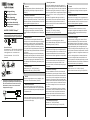
1. Empfohlenes Erdungskonzept/Recommended
grounding concept/Concept recommandé pour la
mise à la terre/Sistema di messa a terra consig-
liato/istema de puesta a tierra recomendado/
Экранирование корпуса
DE
2. Allgemein
Bestimmungsgemässer Gebrauch, Inbetriebnahme, Mon-
tage, Entsorgung siehe Beileger «Allgemeine Hinweise»
(11042373).
3. Zusätzliche Informationen
Diese Montageanleitung ist eine produktspezische Ergän-
zung zu den allgemeinen Dokumenten. Für den Einsatz als
Standardkomponente in Sicherheitsfunktionen, fordern Sie
bitte die mitgeltende «Application Note» an.
4. Wartung
Der Drehgeber ist wartungsfrei und darf nicht geöffnet
beziehungsweise mechanisch oder elektrisch verändert
werden. Ein Öffnen des Drehgebers kann zu Verletzungen
führen.
5. Montagehinweise
Auf korrekten Anbau und störungsfreien Betrieb achten.
Fremdkörper sind in ausreichendem Abstand zur Kupplung/
Statorkupplung zu halten. Antriebs- und Drehgeberwelle
über eine geeignete Kupplung, Drehmomentstütze verbin-
den (siehe Zubehör). Keine starre Verbindung vornehmen,
es ist in jedem Fall ein Ausgleichselement vorzusehen. Die
Montage mit nach oben gerichteter Welle bzw. Anschluss ist
zu vermeiden.
Hohlwelle: Bei Anwendungen mit hoher Schockbelastung
wird empfohlen den Drehgeber mit Loctite an der Welle zu
befestigen. Ein Betrieb an den Grenzen der Spezikation
kann zu einer Verringerung der Lebensdauer führen. Zen-
trische Montage ohne Krafteinwirkung sicherstellen (Siehe
Kapitel 8/9).
6. Technische Daten
Betriebsspannung:
10...30 VDC (UL Class 2)
Betriebsstrom ohne Last: typ. 20 mA (24 VDC)
EN
2. General
Instructions for appropriate use, set-up, installation, dispo-
sal see insert «General Information» (11042373).
3. Additional informations
These assembly instructions are a product-specic sup-
plement to the general documents. For usage as standard
component in safety functions, please request the applica-
ble «Application note».
4. Maintenance
The encoder is maintenance-free and must not be opened
up nor mechanically or electronically modied. Opening up
the encoder can lead to injury.
5. Mounting instructions
Ensure correct installation and trouble-free operation. Fo-
reign objects must be kept at a sufcient distance from the
coupling / stator coupling. Connect drive and encoder shaft
with a suitable coupling (see accessories). Avoid rigid con-
nection. In any case the use of a torque element is required.
Mounting with shaft or connector pointing upwards has to
be avoided.
Hollow shaft: For applications with high shock load it is
recommended to x the encoder with Loctite to the shaft.
Operation at the limits of the specication can lead to a
reduction in service life. Ensure centric installation without
force (see chapter 8/9).
6. Technical data
Voltage supply:
10...30 VDC (UL Class 2)
Consumption w/o load: typ. 20 mA (24 VDC)
FR
2. Générales
Instructions pour une utilisation appropriée, Mise en
service, Installation/Montage, Éliminatión voir les annexes
«Informations générales» (11042373).
3. Informations supplémentaires
Ces instructions de montage sont un complément spéci-
que aux documents généraux. Pour une utilisation en tant
que composant standard dans les fonctions de sécurité,
veuillez demander la «Note d‘application» correspondante.
4. Maintenance
Le codeur est sans entretien et ne doit pas être ouvert
ni mécaniquement ou électriquement modié. En cas
d‘ouverture du codeur, les ressorts risquent de provoquer
des blessures
5. Instructions de montage
Veiller à une installation correcte et à un fonctionnement
parfait. Maintenir les corps étrangers à distance sufsante
de l’accouplement. Raccorder les arbres d’entraînement et
du codeur au moyen d’un accouplement / ressort anti-rota-
tion approprié (voir accessoires). Ne pas raccorder l’arbre
du codeur et l’arbre d’entraînement de manière rigide. Dans
tous les cas, il convient de prévoir un élément de compen-
sation. Éviter le montage avec l’axe ou le raccord orienté
vers le haut.
Axe creux: en cas d’applications exigeant une résistance
aux chocs élevée, nous recommandons de xer le codeur
à l’axe à l’aide de Loctite. Une opération à la limite de la
spécication peut conduire à une réduction de la durée
de vie. Assurer une installation centrée sans force (voir le
chapitre 8/9).
6. Caractéristiques techniques
Alimentation:
10...30 VDC (UL Class 2)
Courant de service sans charge: typ. 20 mA (24 VDC)
IT
2. Generali
Istruzioni per un uso conforme, messa in funzione, mon-
taggio, smaltimento vedi allegati «Informazioni generali»
(11042373).
3. Ulteriori informazioni
Queste istruzioni di montaggio sono un supplemento spe-
cico del prodotto ai documenti generali. Per l‘utilizzo come
componente standard in funzioni di sicurezza, si prega di
richiedere la «Nota applicativa» applicabile.
4. Manutenzione
L‘encoder non necessita di manutenzione, non deve
essere aperto e neppure essere sottoposto a modiche
meccaniche o elettriche. Un‘apertura dell‘encoder può
comportare delle lesioni.
5. Istruzioni di montaggio
Fare attenzione che il montaggio sia corretto e il funzio-
namento senza interferenze. Corpi estranei vanno tenuti
a debita distanza dal giunto di accoppiamento / accoppia-
mento dello statore. Albero motore e albero encoder vanno
collegati tramite apposito giunto di accoppiamento (vedi
accessori). Non eseguire alcun collegamento rigido. In ogni
caso va previsto un elemento di compensazione. Va evitato
il montaggio con l‘albero e/o il collegamento orientato verso
l‘alto.
Albero cavo: nelle applicazioni con elevata sollecitazione
improvvisa si consiglia di ssare l‘encoder all‘albero con
loctite. Un‘operazione ai limiti della specica può provocare
una riduzione della durata di vita. Garantire un‘installazione
centrica senza forzature (vedi il capitolo 8/9).
6. Dati tecnici
Tensione d’esercizio: 10...30 VDC (UL Class 2)
Corrente di esercizio senza carico: typ. 20 mA (24 VDC)

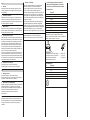
7.1 Standard Cable
CANopen
®
BN +Vs
WH 0 V
GN CAN_H
YE CAN_L
GY CAN_GND
PK n.c.
BU n.c.
RD n.c.
Kabelschirm: Schirm mit Gehäuse verbunden / Shield:
connected to housing / Blindage: Relié au boîtier
Schermo: collegato alla custodia / Escudo: conectado a la
carcasa / Экран: подключен к корпусу
E311
Absolute Encoder MAGRES
EAM580-SY6.7L4B.14130.A-11082567
4.5 – 30 VDC, SSI
ww
w.baumer.com Made in Switzerland
1 0 V 5 Data+
2
+Vs 6 Data-
3
Clock+ 7 SET
4
Clock- 8 Data-
7.2 Standard M12
Pin CANopen
®
1 CAN_GND
2 +Vs
3 0 V
4 CAN_H
5 CAN_L
1
2
3
4
5
kundenspezisch / customer specic
spéciques aux clients / specici del
cliente / especícos del cliente
Специализированный сайт
R
ø
8x0,09 mm
2
ø = 4,8 mm
R x ≥24 mm
5. Указания по монтажу
Обеспечьте правильный монтаж и бесперебойную
работу. Иностранные тела должны находиться
на достаточном расстоянии от муфты сцепления/
статора. Соедините валы привода и датчика с
помощью подходящей муфты, моментного рычага (см.
Принадлежности). Не делайте жесткого соединения;
всегда должен быть предусмотрен компенсирующий
элемент. Избегайте монтажа на валу или соединения,
направленного вверх.
Полый вал: Для применений с высокими ударными
нагрузками рекомендуется закрепить кодирующее
устройство на валу с помощью Loctite. Эксплуатация в
пределах спецификации может привести к сокращению
срока службы. Убедитесь в том, что центральный
монтаж выполнен без применения силы (см. главу 8/9).
6. Технические характеристики
Рабочее напряжение: 10...30 VDC (UL Class 2)
Рабочий ток без нагрузки: печатать. 20 mA (24 VDC)
ES
2. General
Instrucciones para el uso adecuado, puesta en servicio,
montaje, eliminación ver los adjuntos «Información gene-
ral» (11042373).
3. Información adicional
Estas instrucciones de montaje son un suplemento espe-
cíco de los documentos generales. Para usar como un
componente estándar en funciones de seguridad, solicite
la «Nota de aplicación» aplicable.
4. Mantenimiento
El encoder no necesita mantenimiento. No está permitido
abrirlo ni realizar cambios mecánicos o eléctricos. Abrir el
encoder puede provocar lesiones.
5. Instrucciones de montaje
Debe observarse un correcto montaje y funcionamiento sin
fallos. Debe mantenerse los cuerpos extraños a una distan-
cia suciente del acoplamiento / acoplamiento del estator.
Unir el árbol motor y el eje del encoder mediante un aco-
plamiento apropiado. (Véase los accesorios). No realizar
una unión rígida. En todo caso se deberá disponer de un
elemento de compensación. Debe evitarse el montaje con
el eje o la conexión orientados hacia arriba.
Eje hueco: en aplicaciones con una elevada carga de cho-
que se recomienda jar el encoder al eje con Loctite. Una
operación en los límites de la especicación puede resultar
en una reducción de la vida de servicio. Asegurar la instala-
ción céntrica sin fuerza (ver capitulo 8/9).
6. Especicaciones técnicas
Tensión de servicio:
10...30 VDC (UL Class 2)
Corriente de servicio sin carga
:
typ. 20 mA (24 VDC)
RU
2. Общие указания
Для использования по назначению, ввода в
эксплуатацию, монтажа, утилизации см. прилагаемые
документы «Общие указания» (11042373).
3. Дополнительная информация
Данные инструкции по монтажу являются дополнением
к общим документам, относящимся к конкретному
изделию. Для использования в качестве стандартного
компонента в защитных функциях запросите,
пожалуйста, соответствующее «Указание по
применению».
4. Техническое обслуживание
Энкодер не требует технического обслуживания и не
должен открываться или изменяться механически или
электрически. Открытие датчика может привести к
травмам.
7. Anschlussbelegung/Terminal assignment
Raccordement/Assegnazione dei connettori
Patillaje del conector/Размещение выводов

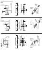
8. Montage / Mounting / Montage / Montaggio / Montaje / Mонтаж
EAM300-SM
EAM300-SM
EAM300-BF
lO0.3A BC
2x
37
TK
O
O
A
C
M2,5
3x 120°
B
10106004
M2,5 DIN 912 / 8.8
recom. torque
0,8
±
0,1Nm
3x M3 x L+5
DIN 912 / 8.8
recom. torque
1,2
±
0.2Nm
36
TK
O
lO0,5A B
A
B
A-A
L
5
+1
16 H7
O
A
1
+0,2
A
A
23
TK
O
lO0.3A BC
A
2x
O 3,4
3x 120°
O
C
A-A
16 H7O
L
A
1
+0,2
A
A
A-A
B
min. 0,1
min. ø 10
A
1x M2,5
A
A
Clamping Ring 10128621
M2,5 DIN 912 / 12.9
recom. torque
0,95
±0,1Nm
M2,5 DIN912 / 8.8
recom. torque
0,8
±0,1Nm

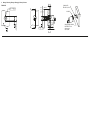
9. Montage / Mounting / Montage / Montaggio / Montaje / Mонтаж
EAM300-BN
B
9,5±0,5
11 ±1
min. O 10
A
min. 0,1
6,5
A
A
_ 0,1A
OD
A-A
Cylindrical Pin
DIN 6325
± 3,0 h6
10123815
Clamping Ring 10128621
M2,5 DIN 912 / 12.9
recom. torque
0,95
±
0,1Nm
27 ±1TK O
lO
0.5A B
A
B
-
 1
1
-
 2
2
-
 3
3
-
 4
4


Baumer EAM300-S - CANopen® Installation and Operating Instructions
- Tipo
- Installation and Operating Instructions
- Este manual también es adecuado para
en otros idiomas
- français: Baumer EAM300-S - CANopen®
- italiano: Baumer EAM300-S - CANopen®
- Deutsch: Baumer EAM300-S - CANopen®
Artículos relacionados
-
Baumer EAM300-S - SSI Installation and Operating Instructions
-
Baumer EAM360-K - CANopen® Installation and Operating Instructions
-
-
-
-
-
-
-
Baumer EAM580R-SC - Analog Installation and Operating Instructions
-