La página se está cargando...

ENGLISH
~
ESPANOL
1
2
3
4L
4R
5
6
7
8
9
A
B
C
K1
1
2
3
4L
4R
5
6
7
8
9
A
B
C
K1
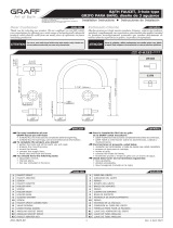
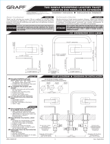
FAUCET SPOUT
BOLT
FAUCET ROSETTE
LEVER
LEVER
BOLT
CAP
HOLDER BASE
SLIDING WASHER
BOLT
FAUCET SPOUT CONNECTION
VALVE SPINDLE
LEVER FIXING SCREW
ANGULAR SOCKET DRIVE
CAÑO DEL GRIFO
PERNO
ROSETA DEL GRIFO
PALANCA
PALANCA
PERNO
TAPA
BASE DE SOPORTE
ARANDELA DE DESPLAZAMIENTO
PERNO
CONEXIÓN AL CAÑO DEL GRIFO
VÁSTAGO DE LA VÁLVULA
TORNILLO PARA FIJAR LA PALANCA
LLAVE DE TUBO ANGULAR
For easy installation of your Para la instalación fácil de su grifo
GRAFF faucet you will need: de la GRAFF usted necesitará:
to READ ALL the instructions completely before beginning, LEER TODAS las instrucciones completamente antes de comenzar,
to READ ALL the warnings, care and maintenance information. LEER TODA la información sobre las advertencias, cuidado y
To complete the project, you should: mantenimiento.
gather the tools and all the parts you will need, Para terminar el proyecto, usted debe:
prepare the mounting area, recolectar las herramientas y todas las piezas que usted necesitará,
mount the faucet, prepare el área para el montaje,
connect the supply lines, monte el grifo,
finally test and flush the faucet. conecte las líneas de fuente,
You should have the following tools: finalmente pruebe y limpie el grifo con un chorro de agua.
adjustable wrench, Usted debe tener las herramientas siguientes:
channel pliers, llave ajustable,
hex key (included in the box). alicates acanalados,
llave hexagonal (incluido en la caja).
ENGLISH
~
ESPANOL
IOG 2824.01 Rev. 1 August 2010
1
Dear Customer Estimado Cliente
Thank you for selecting our product. We are confident we can fully satisfy Muchas gracias por elegir nuestro producto. Estamos seguros que podemos
your expectations by offering you a wide range of technologically advanced satisfacer completamente sus expectativas ofreciéndole una amplia variedad
products which directly result from our many years of experience in faucet de productos tecnológicamente avanzados que resultan directamente de
and fitting production. muchos años de experiencia en grifos y su producción apropiada.
ENGLISH
~
ESPANOL
This faucet complies with NSF61/9, ASME/ANSI A112.18.1
and CSA B 125 Standards.
Este grifo se encuentra conforme con losestandares de NSF61/9,
de ASME/ANSI A112.18.1 y de CSA B 125. Installation Instructions Instrucciones de Instalación
BATH FAUCET, 3-hole type
GRIFO PARA BAÑO, diseño de 3 agujeros
Model
Modelo QUBIC TRE 6250-LM39B-**-T
For care, use soft towel with soap and water only! Under no
circumstances should you use any chemicals.
ATTENTION! ATENCIÓN! Para el cuidado, utilice solamente una toalla suave con jabón
y aqua! Bajo ninguna circunstancia no use productos químicos.
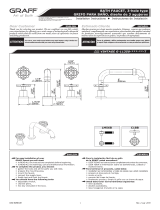
2-3/16"
(55mm)
□1-3/4"
(□45mm)
□1-3/4"
(□45mm)
□1-3/4"
(□45mm)
9-1/8" (231mm)
4-5/8" (118mm)
3/8" (10mm)
1/4" (6.5mm)
1-1/4"
(32mm)
8-1/2" (216mm)
1-3/16" ( 30mm)
□□
1-3/16"
(30mm)

IOG 2824.01 Rev. 1 August 2010
2
This faucet complies with NSF61/9, ASME/ANSI A112.18.1
and CSA B 125 Standards.
Este grifo se encuentra conforme con losestandares de NSF61/9,
de ASME/ANSI A112.18.1 y de CSA B 125. Installation Instructions Instrucciones de Instalación
BATH FAUCET, 3-hole type
GRIFO PARA BAÑO, diseño de 3 agujeros
QUBIC TRE
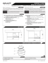
1
2.1 2.2 2.3
~
ESPANOL
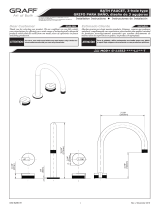
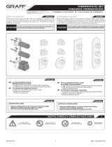
See fig. 2.1-2.3
1. Slide the faucet rosette (3) onto the installed faucet connector (A)
from above (fig. 2.1).
2. Slide the faucet spout (1) onto the faucet connector (A) (fig. 2.2).
3. Fit the bolt (2) using the key (K1) (fig. 2.3).
Ver las figs. 2.1-2.3
1. Deslice la roseta del grifo (3) en el conector del grifo instalado (A)
desde arriba (fig. 2.1)
2. Deslice el caño del grifo (1) en el conector del grifo (A) (fig. 2.2)
3. Ajuste el perno (2) con la llave (K1) (fig. 2.3)
ENGLISH
1
FAUCET INSTALLATION
INSTALACIÓN DEL GRIFO
K1
4L
9 9
4R
5
8 87 3 7
56 62
1
3
AA
1
2K1
1

IOG 2824.01 Rev. 1 August 2010
3
This faucet complies with NSF61/9, ASME/ANSI A112.18.1
and CSA B 125 Standards.
Este grifo se encuentra conforme con losestandares de NSF61/9,
de ASME/ANSI A112.18.1 y de CSA B 125. Installation Instructions Instrucciones de Instalación
BATH FAUCET, 3-hole type
GRIFO PARA BAÑO, diseño de 3 agujeros
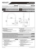
3.1
3.4
3.2
3.5
3.3
3.6
~
ESPANOL
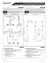
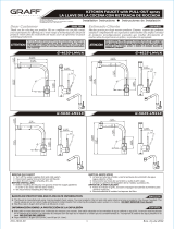
See fig. 3.1-3.6
1. Fit the lever base (7) with the seal already installed (8) from above
(fig. 3.1). Next, fit the bolt (9) using the key (K1) (fig. 3.2).
2. Make sure that the valve is fitted in the closed position. Turn the valve
spindle (B) located on the left of the faucet spout to the right (hot
water), and the spindle located on the right to the left until significant
resistance is felt. Install the lever (4L) (fig. 3.3).
3. If satisfactory alignment of the lever in relation to the bath edge is
impossible (a clear shift from the required position is required – as in
figure (fig. 3.4), remove the lever from the spindle (B), remove the
screw (C) and change the position of the valve spindle (B) by a single
tooth on the splined valve head and refit the bolt in (C) (fig. 3.6).
Attach the lever to the spindle (B) and check if the position is correct.
– If the lever (4L) position is correct, fit the screw (5) using the key
(K1) and fit the cap (6) (fig 3.5).
– If the lever (4L) position is still incorrect – move the valve spindle
(B) by one more tooth on the splined head and check again if the
lever (4L) position is now correct (fig. 3.6).
5. Repeat these steps for the second lever (4R).
Ver las figs. 3.1-3.6
1. Ajuste la base de la palanca (7) con el sello ya instalado (8) desde arriba
(fig. 3.1). Luego, ajuste el perno (9) con la llave (K1) (fig. 3.2).
2. Asegúrese de que la válvula esté ajustada en la posición cerrada. Gire
el vástago de la válvula (B) ubicado a la izquierda del caño del grifo
hacia la derecha (agua caliente), y el vástago ubicado a la derecha
hacia la izquierda hasta sentir una resistencia significativa. Instale la
palanca (4L) (fig. 3.3).
3. Si no es posible lograr una alineación satisfactoria de la palanca en
relación con el borde del baño (se requiere un cambio claro desde la
posición requerida, como en la figura (fig. 3.4) quite la palanca del
vástago (B), quite el tornillo (C) y cambie la posición del vástago de la
válvula (B) en un sólo diente de la cabeza de la válvula dentada y
vuelva a ajustar el perno en (C) (fig.3.6). Conecte la palanca al
vástago (B) y revise si la posición es correcta.
– Si la posición de la palanca (4L) es correcta, ajuste el tornillo (5)
con la llave (K1) y ajuste la tapa (6)
– Si la posición de la palanca (4L) aún es incorrecta - mueva el
vástago de la válvula (B) en un diente más de la cabeza dentada y
revise nuevamente si la posición de la palanca (4L) es correcta
(rys.3.6).
5. Repita estos pasos para la segunda palanca (4R).
(fig 3.5).
ENGLISH
2
LEVER INSTALLATION
INSTALACIÓN DE LA PALANCA
8
7
B8
7
9
K1
4L
Δ Δ
4L K1
5 6
C
B

IOG 2824.01 Rev. 1 August 2010
4
This faucet complies with NSF61/9, ASME/ANSI A112.18.1
and CSA B 125 Standards.
Este grifo se encuentra conforme con losestandares de NSF61/9,
de ASME/ANSI A112.18.1 y de CSA B 125. Installation Instructions Instrucciones de Instalación
BATH FAUCET, 3-hole type
GRIFO PARA BAÑO, diseño de 3 agujeros
~
ESPANOL
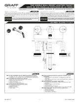
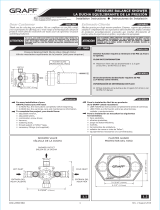
The levers (items 4L and 4R, fig. 1) are designed for full control of the
water stream. Full opening is achieved by opening the lever through 90°:
– clockwise – cold water lever located on the right,
– counterclockwise – hot water lever located on the left).
Water flow adjustment is made over the range 0° - 90°.
Las palancas (puntos 4L y 4R, fig. 1) están diseñadas para el control
completo del flujo de agua. La abertura completa se logra al abrir la
palanca hasta los 90°:
– en el sentido de las agujas del reloj: palanca de agua fría ubicada a
la derecha,
– en sentido contrario a las agujas del reloj: palanca de agua caliente
ubicada a la izquierda.
El ajuste del flujo de agua se realiza sobre el intervalo de 0° a 90°.
ENGLISH
3
METHOD OF OPERATION
MÉTODO DE OPERACIÓN
All dimensions and drawings are for reference only. For details, please refer to actual products.
Todas las dimensiones y dibujos sirven únicamente de referencia. Para consultar detalles, ver los productos.
ENGLISH
~
ESPANOL
4
CARE AND MAINTENANCE
CUIDADO Y MANTENIMIENTO
ENGLISH
~
ESPANOL
WARRANTY
GARANTÍA
Your Graff product is designed and engineered in accordance with the
highest quality and performance standards. Be sure not to damage the
finish during installation. Care should be given to the cleaning of this
product. Although its finish is extremely durable, it can be damaged by
harsh abrasives or polish. Never use abrasive cleaners, acids,
solvents, etc. to clean any Graff product. To clean, simply wipe
gently with a damp cloth and blot dry with a soft towel.
Warranty conditions and warranty registration card are outlined on a
separate sheet.
Su producto de la Graff esta diseńado y dirigido acuerdo con los estándares
de funcionamiento y calidad más altos. Este seguro no dańar las
terminaciones del grifo durante la instalación. Cuide el producto
manteniendolo siempre limpio. Aunque su acabado es extremadamente
durable, puede ser dańado por los abrasivos o pulientes ásperos. Nunca
utilice limpiadores abrasivos, ácidos, solventes, el etc. para limpiar
cualquier producto de la Graff. Para limpiar, simplemente use un
pańo húmedo y seque con una toalla suave.
Las condiciones de la garantía y la tarjeta del registro de la garantía se
encuentran en una pagina separada.
www.graff-designs.com

ENGLISH
~
ESPANOL
1
2
3
4
5
6
7
8
9
10
11
12
13
14
15
1
2
3
4
5
6
7
8
9
10
11
12
13
14
15
HANDLE BASE
BOLT
SLIDING WASHER
LEVER BODY
BOLT WITH HEXAGONAL SOCKET
LEVER ARM
LEVER ASSY
FLAT WASHER
SHOWER HOSE G1/2” FT - M15x1 MT, 59” (1500mm) LENGTH
HOSE NUT CASING
HAND SHOWER BASE
BOLT
SECURING INSERT
FLAT WASHER
HAND SHOWER WITH CHECK-LIMITING VALVE
BASE DEL MANDO
TORNILLO
ARANDELA DESLIZANTE
CUERPO DE LA MANILLA
TORNILLO CON ASIENTO HEXAGONAL
BRAZO DE LA MANILLA
ENSAMBLE DE LA MANILLA
JUNTA PLANA (2 PIEZAS)
MANGUERA DE LA DUCHA R1/2” RI - M15x1 RE, LONGITUD DE
59” (1500mm)
TAPA DE LA TUERCA DE LA MANGUERA
BASE DE LA REGADERA
TORNILLO
INSERTAR DE PROTECCIÓN
JUNTA PLANA
REGADERA CON VÁLVULA DE RETORNO Y RETENCIÓN
IOG 2818.80 1
Dear Customer Estimado Cliente
Thank you for selecting our product. We are confident we can fully satisfy Muchas gracias por elegir nuestro producto. Estamos seguros que podemos
your expectations by offering you a wide range of technologically advanced satisfacer completamente sus expectativas ofreciéndole una amplia variedad
products which directly result from our many years of experience in faucet de productos tecnológicamente avanzados que resultan directamente de
and fitting production. muchos años de experiencia en grifos y su producción apropiada.
ENGLISH
~
ESPANOL
This faucet complies with NSF61/9, ASME/ANSI A112.18.1
and CSA B 125 Standards.
Este grifo se encuentra conforme con losestandares de NSF61/9,
de ASME/ANSI A112.18.1 y de CSA B 125. Installation Instructions Instrucciones de Instalación
SHOWER AND DIVERTER TRIM SET
EL ACABADO DE LA DUCHA Y DE LA VÁLVULA DEL DESVIADOR
Model
Modelo Model
Modelo
M.E.25 6156-LM41B-T QUBIC TRE 6255-LM39B-T
Ø1-1/8"
(Ø28mm)
Ø2"
(Ø50mm)
Ø2"
(Ø50mm)
1-5/16" (34mm)
1/4" (6.5mm)
1-13/16"
(46.5mm)
Ø5/16" (Ø8mm)
8-3/8" (212mm)
~ 9-1/2" (~ 242mm)
Ø
1-1/4" (32mm)
1/4" (6.5mm)
7/16" (12mm)
2-3/16"
(55mm)
1-3/4"
Ø
( 45mm)
Ø
1-3/4"
Ø
( 45mm)
Ø
~ 8-1/8" (~ 207mm)
For easy installation of your Para la instalación fácil de su grifo
GRAFF faucet you will need: de la GRAFF usted necesitará:
to READ ALL the instructions completely before beginning, LEER TODAS las instrucciones completamente antes de comenzar,
to READ ALL the warnings, care and maintenance information. LEER TODA la información sobre las advertencias, cuidado y
To complete the project, you should: mantenimiento.
gather the tools and all the parts you will need, Para terminar el proyecto, usted debe:
prepare the mounting area, recolectar las herramientas y todas las piezas que usted necesitará,
mount the faucet, prepare el área para el montaje,
connect the supply lines, monte el grifo,
finally test and flush the faucet. conecte las líneas de fuente,
You should have the following tools: finalmente pruebe y limpie el grifo con un chorro de agua.
adjustable wrench, Usted debe tener las herramientas siguientes:
channel pliers, llave ajustable,
hex key (included in the box). alicates acanalados,
llave hexagonal (incluido en la caja).
ENGLISH
~
ESPANOL
For care, use soft towel with soap and water only! Under no
circumstances should you use any chemicals.
ATTENTION! ATENCIÓN! Para el cuidado, utilice solamente una toalla suave con jabón
y aqua! Bajo ninguna circunstancia no use productos químicos.
(Ø 25mm)
1"
(190,5mm)
7-1/2"
Rev. 4 June 2017

K1
K2
K1
K2
5/64” (2mm) HEX KEY
3/32” (2.5mm) HEX KEY
MT – male thread
FT – female thread
LLAVE ALLÉN
LLAVE ALLÉN 3/32” (2,5mm)
RE – rosca exterior
RI – rosca interior
5/64” (2mm)
IOG 2818.80 2
This faucet complies with NSF61/9, ASME/ANSI A112.18.1
and CSA B 125 Standards.
Este grifo se encuentra conforme con losestandares de NSF61/9,
de ASME/ANSI A112.18.1 y de CSA B 125. Installation Instructions Instrucciones de Instalación
SHOWER AND DIVERTER TRIM SET
EL ACABADO DE LA DUCHA Y DE LA VÁLVULA DEL DESVIADOR
1.2
M.E.25 6156-LM41B-T
15
14
9
13
11
10
9
8
65
4
3
1
12K12
K2
QUBIC TRE 6255-LM39B-T
1.1
K2
15
14
9
13
11
10
9
8
7
3
1
12K12
Rev. 4 June 2017

IOG 2818.80 3
This faucet complies with NSF61/9, ASME/ANSI A112.18.1
and CSA B 125 Standards.
Este grifo se encuentra conforme con losestandares de NSF61/9,
de ASME/ANSI A112.18.1 y de CSA B 125. Installation Instructions Instrucciones de Instalación
SHOWER AND DIVERTER TRIM SET
EL ACABADO DE LA DUCHA Y DE LA VÁLVULA DEL DESVIADOR
2.1
2.5
2.2
2.6
2.3
2.7
2.4
2.8
1
L
R1
1
R2
31
1
4 5 6
1
L
2
K1
1
Δ
Δ
1
R3
R4
Rev. 4 June 2017

~
ESPANOL
~
ESPANOL
See fig. 2.1-2.11
1. Remove the protective cap (R1) of the collar (R2).
2. Set the knob base (1) with sliding washer (3) on the installation
surface. Place the base in the correct position in relation to the collar
(R2) and secure with a setting screw (2) using the provided hex key
(K1) - figs. 2.2-2.3.
3. Turn the valve spindle to the left as far as possible (to the left). If you
should find it difficult to turn the spindle using your fingers, put the
lever body (4) on the spindle and turn the body to the left as far as
possible and remove the lever body from the spindle.
4. Put the lever body (4) with the screw (5) on the valve spindle
extension (R3) and screw the lever arm (6) - fig. 2.4. Check if it is
possible to obtain the lever position as shown in the picture 2.8. If you
cannot obtain satisfactory position of the lever (A) in relation to the
edge of the installation surface (a clear shift by the angle Δ from the
required position is visible – as shown in the fig. 2.5), take off the lever
(A) from the valve spindle extension (R3) - fig. 2.6. Unscrew the bolt
(R4) and switch the valve spindle extension (R3) by one tooth on the
splines of the valve head and screw in the bolt back (R4) - fig. 2.7 . Put
the lever (A) back on the valve spindle extension (R3) and check if the
lever is set correctly (A) - fig. 2.8.
– If the lever (A) position is correct, unscrew the lever arm (6) and
tighten the screw (5) with the hex key (K2) as shown in fig. 2.9-
2.10. Screw back the lever arm (6) onto the bolt (5) until
resistance is felt - fig. 2.11.
– If the lever (A) position is still incorrect – move the valve spindle
extension (R3) by one more tooth on the splines of the valve head
and check again if the lever (A) position is correct.
See fig. 3.1-3.5
Ver las figs. 2.1-2.11
1. Retire la tapa protectora (R1) de la brida (R2).
2. En la superficie de montaje coloque la base del mando (1) con la
arandela deslizante (3). Posicione la base en relación a la brida (R2) y
asegúrela con el tornillo de fijación (2) usando la llave allén adjunta
(K1) - figs.2.2-2.3.
3. Gire el fuso de la válvula a la izquierda, alcanzando su máximo (en el
sentido antihorario). Si es difícil girar el fuso con los dedos, meta el
fuso en el cuerpo de la manilla (4) y gire el cuerpo a la izquierda y quite
del fuso el cuerpo de la manilla.
4. En la extensión del fuso de la válvula (R3) meta el cuerpo de la manilla
(4) con el tornillo (5), y enrosque el brazo de la manilla (6) - fig. 2.4.
Compruebe si es capaz de posicionar la manilla según la fig. 2.8. Si no
es capaz de obtener la posición adecuada de la manilla (A) en relación
al borde de la superficie de montaje (perciirá un desplazamiento
significativo en el ángulo Δ en relación a la posición requerida – como
en la fig. 2.5), quite la manilla (A) de la extensión del fuso de la válvula
(R3) - fig. 2.6. Desenrosque el tornillo (R4) y desplace la extensión
del fuso de la válvula (R3) por un diente en la multichaveta del cabezal
de la válvula y vuelva a enroscar el tornillo (R4) - fig. 2.7. Vuelva a
meter la manilla (A) en la extensión del fuso de la válvula (R3) y
compruebe la posición de la manilla (A) - fig. 2.8.
– Si la posición de la manilla (A) es correcta, desenrosque el brazo de
la manilla (6) y apriete el tornillo (5) con la llave allén (K2), según
las figs. 2.9-2.10. Vuelva a enroscar el brazo de la manilla (6) en el
tornillo (5) hasta sentir la resistencia - fig. 2.11.
– Si la posición de la manilla (A) sigue siendo incorrecta - desplace la
extensión del fuso de la válvula (R3) por el diente siguiente en la
multichaveta del cabezal de la válvula y vuelva a comprobar la
posición de la manilla (A).
Ver las figs. 3.1-3.5
ENGLISH
ENGLISH
1
2
DIVERTER VALVE TRIM INSTALLATION
INSTALACIÓN EL ACABADO DE LA VÁLVULA DE DESVIADOR
HAND SHOWER TRIM INSTALLATION
INSTALACIÓN EL ACABADO DE LA DUCHA
IOG 2818.80 4
This faucet complies with NSF61/9, ASME/ANSI A112.18.1
and CSA B 125 Standards.
Este grifo se encuentra conforme con losestandares de NSF61/9,
de ASME/ANSI A112.18.1 y de CSA B 125. Installation Instructions Instrucciones de Instalación
SHOWER AND DIVERTER TRIM SET
EL ACABADO DE LA DUCHA Y DE LA VÁLVULA DEL DESVIADOR
2.9 2.10 2.11
5 6 5 65 K2
1. Remove the protective cap (R1) of the collar (R2).
2. Slide the conic nut G1/2” GW on the shower hose (9) and then slide the
shower hose from the thinner end side with thread M15x1 GZ through
the hand base (11) and slide casing (10) over the hose (9) as shown
in fig. 3.2. Connect the hoses (R3) and (9) and remember to install a
flat washer (8) - fig. 3.2.
3. Slide the casing (10) over the place of hose connection (R3) and (9),
remove the lock (R4) from the hose (R3). Move the connected hoses
in the threaded connector (R5) so that the hose connection point
secured with the casing (10) is located under the installation surface -
see fig. 3.3.
1. Retire la tapa protectora (R1) de la brida (R2).
2. Meta la tuerca cónica R1/2” RI en la manguera de ducha (9), luego
meta la manguera de ducha por el extremo más estrecho con rosca
M15x1 RE a través de la base de la regadera (11) y meta en la
manguera (9) la tapa (10), según la fig. 3.2. Una las mangueras (R3)
y (9) sin olvidar de poner la junta plana (8) - fig. 3.2.
3. Metal la tapa (10) donde se unen las mangueras (R3) y (9), quite el
bloqueo (R4) de la manguera (R3). Desplace las mangueras unidas
en el racor roscado (R5) del modo que la zona de unión entre las
mangueras protegida con la tapa (10) se encuentre debajo de la
superficie de montaje - fig. 3.3.
Rev. 4 June 2017

All dimensions and drawings are for reference only. For details, please refer to actual products.
Todas las dimensiones y dibujos sirven únicamente de referencia. Para consultar detalles, ver los productos.
IOG 2818.80 5
This faucet complies with NSF61/9, ASME/ANSI A112.18.1
and CSA B 125 Standards.
Este grifo se encuentra conforme con losestandares de NSF61/9,
de ASME/ANSI A112.18.1 y de CSA B 125. Installation Instructions Instrucciones de Instalación
SHOWER AND DIVERTER TRIM SET
EL ACABADO DE LA DUCHA Y DE LA VÁLVULA DEL DESVIADOR
3.1 3.2 3.3 3.4
R1
11
10
R4
11
9
R4
R5
10
R3
9
11
10
9
8
R3
4. Meta el bloqueo (R4) en la manguera de ducha (9) y asiéntelo en el
racor roscado (R5) - fig. 3.4. En la superficie de montaje posicione la
base de la regadera (11) en relación a la brida (R2) y asegúrela con el
tornillo de fijación (12) usando la llave allén adjunta (K1) -
figs. 3.4-3.5.
5. Una la regadera (15) con la manguera de ducha (9), prestando
atención en la posición correcta de la junta plana (14) en la tuerca
cónica de la manguera - ver la fig. 3.5.
4. Place the lock (R4) on the shower hose (9) and seat it in the threaded
connector (R5) - fig. 3.4. Place the hand shower base (11) in the
correct position on the installation surface in relation to the collar (R2)
and secure with a setting screw (12) using the provided hex key (K1)
- figs. 3.4-3.5.
5. Connect the hand shower (15) with shower hose (9), paying attention
to the correct placement of the flat washer (14) in the hose's conic nut
– see fig. 3.5.
Rev. 4 June 2017
www.graff-designs.com

ENGLISH
~
ESPANOL
4
CARE AND MAINTENANCE,
CUIDADO Y MANTENIMIENTO, WARRANTY GARANTÍA
Your Graff faucet is designed and engineered in accordance with the
highest quality and performance standards. Be sure not to damage the
finish during installation. Care should be given to the cleaning of this
product. Although its finish is extremely durable, it can be damaged by
harsh abrasives or polish. Never use abrasive cleaners, acids,
solvents, etc. to clean any Graff product. To clean, simply wipe
gently with a damp cloth and blot dry with a soft towel.
Warranty conditions and warranty registration card are outlined on a
separate sheet.
Su grifo de la Graff esta diseńado y dirigido acuerdo con los estándares de
funcionamiento y calidad más altos. Este seguro no dańar las terminaciones
del grifo durante la instalación. Cuide el producto manteniendolo siempre
limpio. Aunque su acabado es extremadamente durable, puede ser dańado
por los abrasivos o pulientes ásperos. Nunca utilice limpiadores
abrasivos, ácidos, solventes, el etc. para limpiar cualquier producto
de la Graff. Para limpiar, simplemente use un pańo húmedo y seque
con una toalla suave.
Las condiciones de la garantía y la tarjeta del registro de la garantía se
encuentran en una pagina separada.
~
ESPANOL
See fig. 4.1-4.2
When the lever is set as recommended in the manual: Turning the lever by
180° to the left results in outflow of water through the hand shower,
returning the lever to the starting setpoint results in the outflow of water
through the spout.
Ver la fig. 4.1-4.2
Para la posición de la manilla recomendada en el manual: Girar la manilla
en 180° a la izquierda causa la salida del agua por la regadera, volver con la
manilla a la posición inicial causa la salida del agua por el caño.
ENGLISH
3
DESCRIPTION OF THE OPERATION
DESCRIPCIÓN DEL FUNCIONAMIENTO
IOG 2818.80 6
This faucet complies with NSF61/9, ASME/ANSI A112.18.1
and CSA B 125 Standards.
Este grifo se encuentra conforme con losestandares de NSF61/9,
de ASME/ANSI A112.18.1 y de CSA B 125. Installation Instructions Instrucciones de Instalación
SHOWER AND DIVERTER TRIM SET
EL ACABADO DE LA DUCHA Y DE LA VÁLVULA DEL DESVIADOR
3.5
4.1
4.2
Recommended lever position for the setting point:
water flows out of the shower head
La posición sugerida de la palanca para el ajuste:
salida del agua por la regadera
Recommended lever position for the setting point:
water flows out of the spout
La posición sugerida de la palanca para el ajuste:
salida del agua por el caño
15
14
9
11
12
K1
Rev. 4 June 2017
/