LG Electronics LW8016HR Guía de instalación
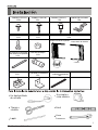
- Tipo
- Guía de instalación

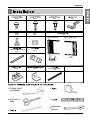
Adjustable
Wrench
Left Guide Panel
Right Guide Panel
Curtain
13 EA
2 EA
3 EA 5 EA
2 EA
2 EA
2 EA
1EA
2 EA
1 EA
1 EA
1 EA
(Not adhesive backed)
( Adhesive backed)
Phillips head
screwdriver
Scissors or
knife
Owner’s Manual 11

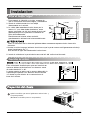
How to Install the Unit
All supporting parts should be secured to firm wood,
masonry, or metal.
This unit is designed for installation in standard double hung
windows with actual opening widths from 22" to 36".
The top and bottom window sash must open sufficiently to
allow a clear vertical opening of 14" from the bottom of the
upper sash to the window stool.
NOTICE
About
1
/2"
30"~60"
Awning
Cooled air
Fence
Over 20"
Heat
radiation
14
3622
12
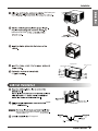
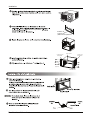
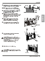
Shipping
Screws
(Keep the screws for later use.)
Remove 4 screws which fasten the cabinet at both
sides and at the back.
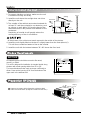
Preparation Of Chassis
1.To prevent vibration and noise, make sure the unit
is installed securely and firmly
2. Install the unit where the sunlight does not shine
directly on the unit.
3.The outside of the cabinet must extend outward for
at least 11" and there should be no obstacles, such
as a fence or wall, within 20" from the back of the
cabinet because it will prevent heat radiation of the
condenser.
Restriction of outside air will greatly reduce the
cooling efficiency of the air conditioner.
All side louvers of the cabinet must remain exposed to the outside of the structure.
4. Install the unit slightly tilted so the back is slightly lower than the front (about
1
/2
").
This will force condensed water to flow to the outside.
5. Install the unit with the bottom between 30"~60" above the floor level.

13
hole
Center hole
the base pan
Adhesive backed
(adhesive backed)
upper
guide
sill support.
frame curtain
8
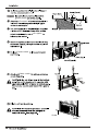
Right Guide Panel
Upper guide
(Type A)
Screws
Frame guide
Left Guide panel

14
Screw
Screw
(removed from the cabinet) at
See page 12.
frame guides
sill support
sill support
frame curtain
frame curtain

slots
14
15
16
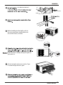
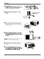
Guide the lever carefully through the grille as
you push it in.
15
16
A screw through the front grille.
Before installing the front grille, pull out
the vent control lever located above the
unit control knobs, as shown.
Lift the inlet grille and secure it with a Type
not adhesive backed
15
Not adhesive backed
Type C

Llave
Francesa
Una regla o
cinta metrica
Nivel
13 EA
2 EA
3 EA 5 EA
2 EA
2 EA
2 EA
1EA
2 EA
1 EA
1 EA
1 EA
(No adhesivo respaldado)
( Adhesivo respaldado)
TORNILLO (TIPO A)
TORNILLO (TIPO B) TORNILLO (TIPO C) DINTEL DE SOPORTE
PERNO
TUERCA MARCO DE LA CORTINA
BURLETE DE ESPUMA
CANO DE DRENAJE
GUIA DEL MARCO
ABRAZADERA DE
FIJACIONA LA VENTANA
BURLETE DE ESPUMA-PE
Grupo Guía de la izquierda
Grupo Guía de derecho
Cortina
Lapiz
Un destornillador
de estrella
Tijeras o
cuchilla
32 Aire Acondicionador

ESPAÑOL
Instalacion
Instalacion
Elija el major lugar
1. Para prevenir la vibración y el ruido, asegure de
que la unidad esté instaalada segura y firmemente.
2. Instale la unidad donde el sol no refleje
directamente en la unidad.
3. La salida debe extenderse hacia afuera por lo
menos 11" y no debe haber obstáculos, como
cercas o paredes, en 20" de la parte de atrás del
gabinete porque va ha prevenir la rediación de
calor del condensador.
Restriciones del aire de afuera reducirá
grandemente la eficiencia del aire acondicionado.
Todas las ventanillas de los lados del gabinete deben mantenerse expuestas hacia afuera de la
estructura.
4 Instale la unidad un poco inclinada de tal forma que la parte trasera esté ligeramente más baja
que el frente(cerca de
1
/2").
Esto forzará el agua del condensador hacia afuera.
5. Instale la unidad con la parte inferior cerca de 30"~60" arriba nivel de suelo.
Esta unidad está diseñada para que sea instalada en
ventanas dobles estándares con una abertura actual
de ancho desde 22" a 36".
La parte superior e inferiro de la ventana debe abrir lo
suficiente para permitir una abertura vertical libre de
14" desde la parte inferior de la ventana hasta la
base de la misma.
Aproximamente
1
/2"
30"~60"
Pabellón
Aire frio
Cerca
Over 20"
Radiacion
de calor
Requistios de ventana
14
3622
Preparcion del chasis
Tornillos
de fijacion
(Mantener los tornillos para su uso posterior.)
Quite los tornillos que unen el gabinete a ambos lados y
a la parte posterior.
Manual del Propietario 33

Instalacion
(Adhesivo respaldado)
Burlete de
espuma-pe
(Adhesivo respaldado)
8
34 Aire Acondicionador
Guia del marco
Grupo Guía
de derecho
Guia superior
(Tipo A)
Tornillos
Grupo Guía de
la izquierda

35
Tipo C
Tipo C
Tipo C
Tipo C
Tornillo
Tornillo

36 Aire Acondicionador
Instalacion
Levante la parrilla de entrada y ajústela
con tornillos Tipo A, através de la parrilla
frontal.
Antes de instalar la parrilla frontal tire hacia
afuera de la control de ventilacion localizada
encima de los botones de control de la unidad,
como se muestra.
(No adhesivo respaldado)
(No adhesivo
respaldado)
14
Guie la palanca cuidadosamente a traves
de la parrilla mientras la empuja.
NOTA
15
16
-
 1
1
-
 2
2
-
 3
3
-
 4
4
-
 5
5
-
 6
6
-
 7
7
-
 8
8
-
 9
9
-
 10
10


