Kichler Lighting 49861BKT Manual de usuario
- Tipo
- Manual de usuario

CAUTION – RISK OF SHOCK – Disconnect Power at the main
circuit breaker panel or main fuse box before starting and during
the installation.
Before Installing:
All installations should comply with National and
local electrical codes. If you have any doubts concerning
installation, contact a qualified licensed electrician.
1) Find the appropriate threaded holes on mounting strap.
Assemble mounting screws into threaded holes.
2) Attach mounting strap to outlet box. (Screws not provided).
Mounting strap can be adjusted to suit position of fixture.
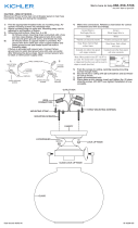
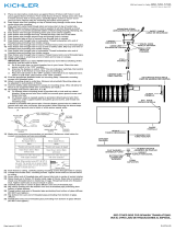
3) Grounding instructions: (See Illus. A or B).
A) On fixtures where mounting strap is provided with a
hole and two raised dimples. Wrap ground wire from
outlet box around green ground screw, and thread into
hole.
B) On fixtures where a cupped washer is provided. Attach
ground wire from outlet box under cupped washer and
green ground screw, and thread into mounting strap.
If fixture is provided with ground wire. Connect fixture
ground wire to outlet box ground wire with wire connector.
(Not provided.) After following the above steps. Never
connect ground wire to black or white power supply wires.
GREEN GROUND
SCREW
CUPPED
WASHER
OUTLET BOX
GROUND
FIXTURE
GROUND
DIMPLES
WIRE CONNECTOR
OUTLET BOX
GROUND
GREEN GROUND
SCREW
FIXTURE
GROUND
A
B
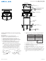
Connect Black or
Red Supply Wire to:
Connect
White Supply Wire to:
Black White
*Parallel cord (round & smooth) *Parallel cord (square & ridged)
Clear, Brown, Gold or Black
without tracer
Clear, Brown, Gold or Black
with tracer
Insulated wire (other than green)
with copper conductor
Insulated wire (other than green)
with silver conductor
*Note: When parallel wires (SPT I & SPT II)
are used. The neutral wire is square shaped
or ridged and the other wire will be round in
shape or smooth (see illus.)
Neutral Wire
Date Issued: 07/28/17
IS-49861-US
SEE OTHER SIDE FOR SPANISH TRANSLATIONS.
VEA EL OTRO LADO DE TRADUCCIONES AL ESPAÑOL.
We’re here to help 866-558-5706
Hrs: M-F 9am to 5pm EST
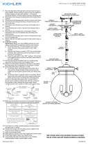
4) Make wire connections (connectors not provided.) Reference
chart below for correct connections and wire accordingly.
5) Push fixture to ceiling, carefully passing mounting screws
through holes in canopy.
6) Thread knurl knobs onto ends of mounting screws. Tighten
knurl knobs to secure fixture to ceiling.
7) Insert recommended bulbs.
8) Raise the glass up through trim into fixture, passing over the
socket.
9) Turn glass to secure glass in place. (DO NOT over tighten)
10) Raise the lower trim over the glass and align the holes to pass
over the studs. Rest lower trim against the upper trim.
11) Slip a washer onto the stud, followed by threading on a finial.
Repeat for remaining studs. Tighten all finials to secure the
trim.
OUTLET BOX
CAJA DE SALIDA
WIRE
CONNECTORS
CONECTORES DE ALAMBRE
(2) STRAP MOUNTING SCREWS
TORNILLOS DE MONTAJE DE LA ABRAZADERA
MOUNTING STRAP
ABRAZADERA DE MONTAJE
FINIAL
CAPUCHÓN
WASHER
ARANDELAS
LOWER TRIM
ADORNO INFERIOR
(2) MOUNTING SCREWS
TORNILLO DE MONTAJE
(2) LOCK-UP KNOBS
PERILLAS DE SUJECIÓN
GLASS
VIDRIO
STUD
CLAVO

PRECAUCIÓN – RIESGO DE DESCARGA ELÉCTRICA – Desco-
necte la electricidad en el panel principal del interruptor automáti-
co o caja principal de fusibles antes de comenzar y durante la
instalación.
Antes de instalar:
Todas las instalaciones deben cumplir con las normas nacionales
y locales Códigos. Si tiene alguna duda sobre la instalación, pón
gase en contacto con un Electricista con licencia.
1) Ensamble los tornillos de montaje en los orificios roscados
en la barra de montaje.
2) Unir la abrazadera de montaje a la caja de conexiones. (No
se proveen tornillos). La abrazadera de montaje puede
ajustarse para acomodar la posición del artefacto.
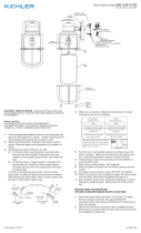
3) Instrucciones de conexión a tierra solamente para los
Estados Unidos.
(Vea la ilustracion A o B).
A) En las lámparas que tienen el fleje, de montaje con un
agujero y dos hoyue los realzados. Enrollar el alambre a
tierra de la caja tomacorriente alrededor del tornillo
verde y pasarlo por el aquiero.
B) En las lámparas con una arandela acopada. Fijar el
alambre a tierra de la caja tomacorriente del ajo de la
arandela acoada y tornillo verde, y paser por el fleje de
montaje.
Si la lámpara viene con alambre a tierra. Conecter el
alambre a tierra de la lámpara al alambre a tierra de la caja
tomacorriente con un conector de alambres (no incluido)
espués de seguir los pasos anteriores. Nunca conectar el
alambra a tierra a los alambres eléctros negro o blanco.
Date Issued: 07/28/17
IS-49861-US
ARANDELA
CONCAVA
TIERRA DE LA
CAJA DE SALIDA
TORNILLO DE TIERRA,
VERDE
DEPRESIONES
TIERRA
ARTEFACTO
CONECTOR DE ALAMBRE
TIERRA DE LA
CAJA DE SALIDA
TORNILLO DE TIERRA,
VERDE
TIERRA
ARTEFACTO
A
B
Conectar el alambre de
suministro negro o rojo al
Conectar el alambre de
suministro blanco al
Negro Blanco
*Cordon paralelo (redondo y liso)
*Cordon paralelo (cuadrado y estriado)
Claro, marrón, amarillio o negro
sin hebra identificadora
Claro, marrón, amarillio o negro
con hebra identificadora
Alambre aislado (diferente del verde)
con conductor de cobre
Alambre aislado (diferente del
verde) con conductor de plata
*Nota: Cuando se utiliza alambre paralelo
(SPT I y SPT II). El alambre neutro es de forma
cuadrada o estriada y el otro alambre será de
forma redonda o lisa. (Vea la ilustracíón).
Hilo Neutral
SEE OTHER SIDE FOR ENGLISH TRANSLATIONS.
VEA EL OTRO LADO DE TRADUCCIONES AL INGLÉS.
We’re here to help 866-558-5706
Hrs: M-F 9am to 5pm EST
4) Haga les conexiones de los alambres (no se proveen los
connectores.) La tabla de referencia de abajo indica las
conexiones correctas y los alambres correspondientes.
5) Empuje el artefacto hacia el techo, pasando cuidadosamente
los tornillos de montaje a través de los orificios en el
escudete.
6) Atornille las perillas estriadas en los tornillos de montaje.
Ajuste las perillas estriadas para fijar el artefacto en el techo.
7) Inserte la bombilla que se recomienda.
8) Levante el vaso a través de la guarnición en el accesorio,
pasando sobre el zócalo.
9) Gire el cristal para asegurar el vidrio en su lugar. (NO apriete
demasiado)
10) Levante el revestimiento inferior sobre el vidrio y alinee los
orificios para pasar sobre los pernos. Descanse el ajuste inferior
contra el borde superior.
11) Deslice una arandela sobre el perno, seguido de roscado en
una flor. Repita para los pernos restantes. Apriete todos los
remates para asegurar el ajuste.
OUTLET BOX
CAJA DE SALIDA
WIRE
CONNECTORS
CONECTORES DE ALAMBRE
(2) STRAP MOUNTING SCREWS
TORNILLOS DE MONTAJE DE LA ABRAZADERA
MOUNTING STRAP
ABRAZADERA DE MONTAJE
FINIAL
CAPUCHÓN
WASHER
ARANDELAS
LOWER TRIM
ADORNO INFERIOR
(2) MOUNTING SCREWS
TORNILLO DE MONTAJE
(2) LOCK-UP KNOBS
PERILLAS DE SUJECIÓN
GLASS
VIDRIO
STUD
CLAVO

CAUTION – RISK OF SHOCK – Disconnect Power at the main
circuit breaker panel or main fuse box before starting and during
the installation.
Before Installing:
All installations should comply with National and
local electrical codes. If you have any doubts concerning
installation, contact a qualified licensed electrician.
1) Find the appropriate threaded holes on mounting strap.
Assemble mounting screws into threaded holes.
2) Attach mounting strap to outlet box. (Screws not provided).
Mounting strap can be adjusted to suit position of fixture.
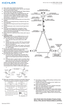
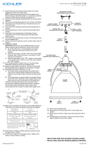
3) Grounding instructions: (See Illus. A or B).
A) On fixtures where mounting strap is provided with a
hole and two raised dimples. Wrap ground wire from
outlet box around green ground screw, and thread into
hole.
B) On fixtures where a cupped washer is provided. Attach
ground wire from outlet box under cupped washer and
green ground screw, and thread into mounting strap.
If fixture is provided with ground wire. Connect fixture
ground wire to outlet box ground wire with wire connector.
(Not provided.) After following the above steps. Never
connect ground wire to black or white power supply wires.
GREEN GROUND
SCREW
CUPPED
WASHER
OUTLET BOX
GROUND
FIXTURE
GROUND
DIMPLES
WIRE CONNECTOR
OUTLET BOX
GROUND
GREEN GROUND
SCREW
FIXTURE
GROUND
A
B
Connect Black or
Red Supply Wire to:
Connect
White Supply Wire to:
Black White
*Parallel cord (round & smooth) *Parallel cord (square & ridged)
Clear, Brown, Gold or Black
without tracer
Clear, Brown, Gold or Black
with tracer
Insulated wire (other than green)
with copper conductor
Insulated wire (other than green)
with silver conductor
*Note: When parallel wires (SPT I & SPT II)
are used. The neutral wire is square shaped
or ridged and the other wire will be round in
shape or smooth (see illus.)
Neutral Wire
Date Issued: 07/28/17
IS-49861-CB
We’re here to help 866-558-5706
Hrs: M-F 9am to 5pm EST
4) Make wire connections (connectors not provided.) Reference
chart below for correct connections and wire accordingly.
5) Push fixture to ceiling, carefully passing mounting screws
through holes in canopy.
6) Thread knurl knobs onto ends of mounting screws. Tighten
knurl knobs to secure fixture to ceiling.
7) Insert recommended bulbs.
8) Raise the glass up through trim into fixture, passing over the
socket.
9) Turn glass to secure glass in place. (DO NOT over tighten)
10) Raise the lower trim over the glass and align the holes to pass
over the studs. Rest lower trim against the upper trim.
11) Slip a washer onto the stud, followed by threading on a finial.
Repeat for remaining studs. Tighten all finials to secure the
trim.
OUTLET BOX
BOÎTE À PRISES
WIRE
CONNECTORS
CONNECTEURS DE FIL
(2) STRAP MOUNTING SCREWS
VIS DE L'ÉTRIER DE MONTAGE
MOUNTING STRAP
ÉTRIER DE MONTAGE
FINIAL
ORNEMENT
WASHER
RONDELLE
LOWER TRIM
MOULURE INFÉRIEUR
(2) MOUNTING SCREWS
VIS DE MONTAGE
(2) LOCK-UP KNOBS
BOULES DE BLOCAGE
GLASS
VERRE
STUD
CLOU

ATTENTION – RISQUE DE DÉCHARGES ÉLECTRIQUES –
Couper le courant au niveau du panneau du disjoncteur du
circuit principal ou de la boîte à fusibles principale avant de
procéder à l’installation.
Avant d’installer:
Toutes les installations doivent être conformes aux normes nation
ales et Codes électriques locaux. Si vous avez des doutes concer
nant Installation, contactez un électricien qualifié agréé.
1) Trouver les trous filetés appropriés sur la barrette de montage.
Vissez les vis de montage dans les trous filetés.
2) Visser la barrette de montage à la boite de jonction. (Vis non
fournies). La barrette de montage peut etre ajustée pour
convenir à la position de l’applique.
3) Connecter les fils (connecteurs non fournis). Se reporter au
tableau ci-dessous pour faire les connexions.
Date Issued: 07/28/17
IS-49861-CB
Connecter le fil noir ou
rouge de la boite
Connecter le fil blanc de la boîte
A Noir A Blanc
*Au cordon parallèle (rond et lisse)
*Au cordon parallele (à angles droits el strié)
Au bransparent, doré, marron, ou
noir sans fil distinctif
Au transparent, doré, marron, ou
noir avec un til distinctif
Fil isolé (sauf fil vert) avec
conducteur en cuivre
Fil isolé (sauf fil vert) avec
conducteur en argent
*Remarque: Avec emploi d’un fil paralléle
(SPT I et SPT II). Le fil neutre est á angles
droits ou strié et l’autre fil doit étre rond ou
lisse (Voir le schéma).
Fil Neutre
We’re here to help 866-558-5706
Hrs: M-F 9am to 5pm EST
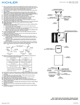
4) Pousser le luminaire vers le plafond en passant soigneusement
les vis de montage par les trous dans le cache.
5) Visser les boutons moletés sur les vis de fixation. Resserrer les
boutons moletés pour fixer le luminaire au plafond.
6) Introduire l’ampoule recommandée.
7) Soulever le verre à travers la garniture dans le luminaire, en
passant sur la prise.
8) Tournez le verre pour sécuriser le verre en place. (NE PAS
serrer trop)
9) Relevez la garniture inférieure sur le verre et alignez les trous
pour passer sur les goujons. Reposez la garniture inférieure
contre la garniture supérieure.
10) Glisser une rondelle sur le goujon, suivie d’un filetage sur un
bout. Répétez pour les goujons restants. Serrez tous les finials
pour fixer la garniture.
OUTLET BOX
BOÎTE À PRISES
WIRE
CONNECTORS
CONNECTEURS DE FIL
(2) STRAP MOUNTING SCREWS
VIS DE L'ÉTRIER DE MONTAGE
MOUNTING STRAP
ÉTRIER DE MONTAGE
FINIAL
ORNEMENT
WASHER
RONDELLE
LOWER TRIM
MOULURE INFÉRIEUR
(2) MOUNTING SCREWS
VIS DE MONTAGE
(2) LOCK-UP KNOBS
BOULES DE BLOCAGE
GLASS
VERRE
STUD
CLOU
-
 1
1
-
 2
2
-
 3
3
-
 4
4


Kichler Lighting 49861BKT Manual de usuario
- Tipo
- Manual de usuario
en otros idiomas
Artículos relacionados
-
 Kichler Lighting 42296NI Manual de usuario
-
 Kichler Lighting 49857BKT Manual de usuario
-
 Kichler Lighting 42474PN Manual de usuario
-
Kichler Lighting 43194MIZ Manual de usuario
-
 Kichler Lighting 43754AUB Manual de usuario
-
 Kichler Lighting 42588OZ Manual de usuario
-
 Kichler Lighting 43737CLP Manual de usuario
-
 Kichler Lighting 42879NI Manual de usuario
-
 Kichler Lighting 43755AUB Manual de usuario
-
 Kichler Lighting 44033NI Guía de instalación


