GE ZSB9231NSS Guía de instalación

Categoría
Cocinas
Tipo
Guía de instalación

Este manual también es adecuado para

INSTALLATION
INSTRUCTIONS
Advantium
®
Built-In Wall Oven
240V 30”
MONOGRAM.COM
MFL59060933
Para consultar una version en español de este manual
de instrucciones, visite nuestro sitio de internet Monogram.com.
2 31-7000080 Rev. 2
Safety Information
CONTENTS
Design Information
Models Available
...............................................2
Product Dimensions and Clearances
................3
Tools and Parts Required
.................................3
Advance Planning
.............................................3
Installation Preparation
Electrical Requirements
....................................4
Install Junction Box
...........................................4
Preparing the Opening (Installation without
an accessory storage drawer)
........................5
Flush Mount
......................................................7
With Accessory Storage Drawer
.......................8
Installation Instructions
Step 1, Remove Packaging and Parts
.............. 9
Step 2, Route Conduit
.....................................10
Step 3, Install Bottom Trim
..............................11
Step 4, Install Mounting Screws
......................11
Step 5, Finalize Installation
.............................11
MODELS AVAILABLE
ZSB9231NSS – Stainless Steel
ZSB9232NSS – Stainless Steel
BEFORE YOU BEGIN
Read these instructions completely and
carefully.
IMPORTANT
Save these instructions
for local inspector’s use.
IMPORTANT
Observe all governing codes and
ordinances.
Note to Installer
Be sure to leave these
instructions with the Consumer.
Note to Consumer
Keep these instructions
with your Owner’s Manual for future reference.
Skill Level Installation of this appliance
requires basic mechanical and electrical skills.
Completion Time
1 Hour.
Proper installation is the responsibility
of the installer. Product failure due to improper
installation is not covered under the warranty.
See Owner’s Manual for warranty information.
IMPORTANT
Use this oven only for its
intended purpose. Never use the oven for warming or
heating a room. Prolonged use of the oven without
proper ventilation can be hazardous.
CAUTION
For personal safety, remove
house fuse or oven circuit breaker before beginning
installation to avoid severe or fatal shock injury.
CAUTION
For personal safety, the
mounting surface must be capable of supporting the
cabinet load, in addition to the added weight of the
oven and drawer, plus additional oven loads.
31-7000080 Rev.2 3
Design Information
PRODUCT DIMENSIONS AND CLEARANCES NOTE: Appearance will vary by model.
TOOLS AND PARTS REQUIRED
(NOT SUPPLIED)
#2 Phillips screwdriver
Hand held drill
High speed drill bit, 3/32" diameter
3/8" slot head screwdriver
Level
Saw
2x4 or 2x2 lumber for installing runners
or 3/8" plywood for floor (if required)
Wood screws or other hardware for installing runner or
shelf to support oven (if required)
Safety glasses or goggles
ELECTRICAL TOOLS AND PARTS
REQUIRED (NOT SUPPLIED)
Junction box
Electrical cable (3-conductor or 4-conductor wire as
required by local codes)
UL-listed conduit connectors
Wire cutters and wire strippers
ADVANCE PLANNING
These ovens may be installed directly into a 30”
wide oven cabinet.
Cutout dimensions are NOT the same for
installation with or without an accessory storage
drawer. Make sure to use the correct cutout when
preparing the opening.
IMPORTANT This oven is not
approved for use above another built-in Advantium
Speedcook oven, a side by side installation or below
a countertop.
For personal safety, this oven cannot be installed
in a cabinet arrangement such as an island or
peninsula.
The oven must be installed at least 36-3/4” above
the floor.
Allow for clearance to adjacent corners, walls,
drawers, etc.
Cabinets installed adjacent to wall ovens must have
an adhesion spec of at least 194ºF temperature rating.
The oven must be securely installed in a cabinet that
is firmly attached to the house structure. Weight on
the oven door could cause the oven
to tip and result in injury. Never allow anyone to
climb, sit, stand or hang on the oven door.
If installing the drawer accessory, the drawer must
be assembled to the oven prior to installation into
the cabinet. See the Accessory Storage Drawer
Assembly Instructions.
FLUSH MOUNT INSTALLATION
This installation method allows for the unit face to be
inline with the cabinet face.
IMPORTANT: HIGH SKILL LEVEL IN CARPENTRY
IS REQUIRED. Non-standard cabinetry may be
required.
Flush installation of the oven will lead to the exposure
of the cabinet face frame edges.
Side cleats may be visible and should be a finished
surface.
Model Door Depth
ZSB9231NSS 1-3/8”
ZSB9232NSS 1-7/16”
20-1/4”
29-3/4”
21-1/2Ǝ
1Ǝ
13 1/4Ǝ
2-1/4Ǝ
Door Depth
See table
below
4 31-7000080 Rev. 2
Installation Preparation
INSTALL JUNCTION BOX
The conduit is located at the top right on the back of the
oven.
Locate and install the junction box within reach of the
oven conduit.
Through the left or right sides of the cabinet wall
and into adjacent cabinet.
Or, through the cutout floor.
Or, in the upper cabinet.
Cutout
Height
ELECTRICAL REQUIREMENTS
Single Advantium Installation
Product rating is 120/208 or 120/240 volt, 60 Hz,
30 amps. This product must be connected to a supply
circuit of the proper voltage and frequency and protected
by a time delay fuse or circuit breaker. Power should be
supplied from a separate, dedicated 30-ampere branch
circuit. Wire size must conform to the requirements of the
National Electrical Code or the prevailing local code.
Combined Advantium and Wall Oven Installation
When installed in combination with a single wall oven, use
separate electrical junction boxes.
Refer to single oven installation instructions for electrical
requirements of that product.
These connections must be made by a qualified
electrician. All electrical connections must meet National
Electrical Code or prevailing local codes.
Combined Advantium and Warming Drawer
Installation
When installing the Advantium oven over an electric
warming drawer, a separate 120V, 60Hz, properly
grounded receptacle must be installed. See instructions
packed with the warming drawer.
WARNING
The electrical power to the oven branch circuit must
be shut off while line connections are being made.
Use copper wiring only.
Electrical ground is required on this appliance. The
free end of the green wire (ground wire) must be
connected to a suitable ground. This wire must remain
grounded to the oven.
If cold water pipe is interrupted by plastic,
non-metallic gaskets, union connections or other
insulating materials, DO NOT use for grounding.
DO NOT ground to a gas pipe.
DO NOT have a fuse in the NEUTRAL or
GROUNDING circuit. A fuse in the NEUTRAL or
GROUNDING circuit could result in an electrical shock.
Check with a qualified electrician if you are in doubt
as to whether the appliance is properly grounded.
Failure to follow these instructions could result in
serious injury or death.
GROUNDING INSTRUCTIONS
WARNING
Improper use of the grounding plug can result in a risk of electric shock.
This appliance must be connected to a grounded, metallic, permanent wiring system, or an equipment
grounding conductor should be run with the circuit conductors and connected to the equipment grounding
terminal or lead on the appliance.
31-7000080 Rev.2 5
Standard Installation Preparation
PREPARE THE OPENING
The Advantium 240V can be installed in combination
with other Monogram Built-In appliances. Always
follow each product’s Installation Instructions to
complete the installation.
Single Advantium 240V Installation:
Order a 30” wide single oven cabinet or cut the
opening in a wall to the dimensions shown.
30”
23-1/2”
25-1/4”
17-1/2”
Construct
Base
Min. 3/8”
Plywood
Supported
by 2x4
or 2x2
Runners all
Four Sides
36-3/4”
Min.
Always maintain 36-3/4” minimum height from the floor
to the cutout in any single or combined installation.
Allow the following clearances around the cutout on the
IURQWVXUIDFHRIWKHFDELQHWí´IURPWKHWRSí´
IURPWKHVLGHHGJHVDQGí´IURPWKHERWWRP1RWH
these refer to minimum clearances required for installation
and do not reflect actual product dimensions.)
Oven overlaps will conceal cut edges on all sides of
the opening.
When installed over a single oven or a warming
drawer, allow at least 2” between the two openings.
This separation will provide clearance for bottom
overlap of the Advantium 240V and the other
appliance overlaps.
Construct a solid oven floor of 3/8” min. thick plywood
supported by 2 x 4 or 2 x 2 runners on all sides.
The support must be level and rigidly mounted, flush
with the bottom edge of the cutout.
PREPARE THE OPENING (CONT.)
Installation over a Warming Drawer:
30”
23-1/2”
25-1/4”
17-1/2”
36-3/4”
Min.
2” Min.
(3”
recommended)
Per warming
drawer
requirement
Construct
Solid Bottom
Min. 3/8”
Plywood
Supported
by 2x4 or 2x2
Runners all
Four Sides
NOTE: Additional clearances between the cutouts
may be required. Check to be sure the oven supports
above the Warming Drawer location do not obstruct
the required interior depth and height. See Warming
Drawer installation instructions for details.
IMPORTANT: Always maintain 36-3/4” minimum height from the floor to the cutout in any single or combined
installation.
6 31-7000080 Rev. 2
Standard Installation Preparation
PREPARE THE OPENING (CONT.)
Installation over a Wall Oven and
Warming Drawer:
Construct
Solid Bottom
Min. 3/8”
Plywood
Supported
by
2x4 or 2x2
Runners all
Four Sides
30”
23-1/2”
25-1/4”
17-1/2”
2” Min.
Per Oven
Requirement
45-1/4”
Min.
Per warming drawer requirement
2” Min.
(3” recommended)
NOTE: Additional clearances between the cutouts
may be required. Check to be sure the oven supports
above the Warming Drawer location do not obstruct
the required interior depth and height. See Warming
Drawer installation instructions for details.
CAUTION
For personal safety, the mounting
surface must be capable of supporting the cabinet
load, in addition to the added weight of the oven and
drawer, plus additional oven loads.
PREPARE THE OPENING (CONT.)
Installation over a Wall Oven:
30”
23-1/2”
25-1/4”
17-1/2”
2” Min.
(3” recommended)
45-1/4”
Min.
Construct
Solid Bottom
Min. 3/8”
Plywood
Supported by
2x4 or 2x2
Runners all
Four Sides
Per Oven
Requirement
• If you are replacing an electric double oven with the
combined installation of an Advantium 240V and a
single oven, use the dimensions shown. The middle
rail separating the two openings may need to be
larger than the 2” minimum shown.
IMPORTANT: Always maintain 36-3/4” minimum height from the floor to the cutout in any single or combined
installation.
31-7000080 Rev.2 7
Flush Mount Installation Preparation
PREPARE THE INTERIOR
Cut and install side cleats:
Cut side wood cleats to height of cabinet opening
and approx. 2-1/2” in depth. Install, on each side,
Dim. E (See table below) from the front face of the
cabinet.
Cut and install bottom cleat:
Cut bottom wood cleat to a height of 1-1/8”, a depth
of the cabinet minus Dim. E (See table below) and
a width of 25-1/4” to fit between side cleats. Install
onto the cabinet floor between the side cleats, push
it all the way back against cabinet wall and make
sure its front face aligns with the front faces of the
side cleats (Dim. E, from the table below, gap from
the front cabinet face).
E
C
B
D
A
A
A Side and top cleats depth 2-1/2” min.
B Bottom cleat height 1-1/8”
C Bottom cleat depth Cabinet depth minus Dim E.”
D Bottom cleat width 25-1/4”
E All four cleats inset depth ZSB9231NSS: 1-3/8”
ZSB9232NSS: 1-7/16”
TOP
VIEW
Front Face of Cabinet
EE
A A
C
D
PREPARE THE OPENING
The Advantium Built-In Oven can be installed
in combination with other Monogram Built-In
ovens. Always follow each product’s Installation
Instructions to complete the installation.
Single Advantium Built-In Oven
Installation:
Cut the opening in a cabinet to the dimensions
shown.
**20 1/2”
Construct
solid bottom
- Min. 3/8”
plywood
supported on
all four sides.
Must be able to
support weight
of oven and
contents.
36-3/4”
Min.
F *
23-1/2” min.
• The support must be level and rigidly mounted,
flush with the bottom edge of the cutout.
Approved Flush Installation
Dimension F
1/8” Reveal 1/4” Reveal
Single Advantium 30” 30-
1
/4
Over Warming Drawer 30” 30-
1
/4
Over Oven
30” 30-
1
/4
Over Oven and Warming Drawer
30” 30-
1
/4
** Top and bottom reveals are set to
1
/8”.
2” min.
(3” recommended)
Per appliance
specs.
Oven or
warming drawer
8 31-7000080 Rev. 2
Installation Preparation with Accessory Storage Drawer
PREPARE THE OPENING (cont.)
The Advantium Built-In Oven can be installed in combination with other Monogram appliances. Always follow each
product’s Installation Instructions to complete the installation.
Single Advantium Built-In Oven Installation:
Order a 30Ǝ wide single oven cabinet or cut the opening in a wall to the dimensions shown.
Dimension 1/8”
Reveal
1/4”
Reveal
K 30” 30-1/4”
Preparation with an Accessory Storage Drawer
As needed, see the Standard Mount Installation Preparation OR Flush Mount Installation Preparation for
configuration details. Note the modified cutout height below.
30Ǝ
23-1/2Ǝ
25-1/4Ǝ
Min.
21Ǝ
36-3/4Ǝ
Min.
Construct
solid bottom - Min.
3/8” plywood
supported
on all four sides.
Must be able to
support weight
of oven and
contents.
STANDARD MOUNT:
23-1/2Ǝ
K*
23-5/8Ǝ
36-3/4Ǝ
Min.
Construct
solid bottom - Min.
3/8” plywood
supported
on all four sides.
Must be able to
support weight
of oven and
contents.
FLUSH MOUNT:
For flush installation, make the bottom cleat height 3/4” when installed over a storage drawer.
$OORZWKHIROORZLQJFOHDUDQFHVDURXQGWKHFXWRXWRQWKHIURQWVXUIDFHRIWKHFDELQHWí´IURPWKHWRSí´
from the side edges, and 3/4” from the bottom. (Note: these refer to minimum clearances required for installation
and do not reflect actual product dimensions.)
Oven overlaps will conceal cut edges on all sides of the opening.
When installed over a single oven or a warming drawer, allow at least 2Ǝ between the two openings. This
separation will provide clearance for bottom overlap of the Advantium Built-In Oven and the other appliance
overlaps.
The support must be level and rigidly mounted, flush with the bottom edge of the cutout.
31-7000080 Rev.2 9
Installation Instructions
1
REMOVE THE PACKAGING AND PARTS
• Remove all packing material and tape.
• Locate parts package containing mounting
screws.
• Remove the oven from the carton. Do not lift unit
by handle or conduit. Two people are required to
lift this oven.
• Open the door and remove any packaging in
oven.
Owner’s
Manual
Owner’s Manual
Installation
Instructions
Glass Tray
Metal Grill Tray
Turntable Ring
Rack
Cooking Guide
Cooking
Guide
Metal Tray
Bottom Trim
IMPORTANT: If installing the Advantium Built-In
Oven with an accessory storage drawer, read the
storage drawer assembly instructions to assemble
the products together before proceeding to Step 2.
5 Color-Matched Screws
(4 required, 1 extra)
8 Brass Screws for the
Bottom Trim
(3 required, 5 extra)
Flat-Head Screws (4 extra)
10 31-7000080 Rev. 2
Installation Instructions
2
ROUTE CONDUIT THROUGH
CUTOUT
CAUTION
Two people are required to lift
the oven into the opening.
Grasp the bottom at front and rear. Discard foam
base. DO NOT USE HANDLE OR CONDUIT TO
LIFT THE OVEN. DAMAGE WILL OCCUR.
With oven in front of the cabinet opening:
Insert conduit into cabinet opening. Connect oven
wiring and branch circuit.
Lift the oven into the opening while continuing to feed
the conduit in the direction of the installed junction
box. Be sure the conduit does not get pinched
between the back of the oven and the cabinet wall.
Leave oven a few inches forward of the cabinet
front frame. Do not push the unit all of the way into
the cutout.
(Oven shown without
accessory storage drawer.)
WARNING
Disconnect power to the junction box before
making the electrical connection.
Electrical ground is required on this appliance.
Do not connect the electrical supply until appliance
is permanently grounded.
2
ROUTE CONDUIT THROUGH
CUTOUT (CONT.)
When connecting to a 3-conductor branch
circuit:
Connect oven red lead to branch circuit red lead.
Connect oven black lead to branch circuit black lead.
Connect oven green ground lead and white lead
to branch circuit neutral (white or gray).
When connecting to a 4-conductor branch
circuit:
Connect oven red lead to branch circuit red lead.
Connect oven black lead to branch circuit black lead.
Break connection between oven white lead and
oven green ground lead.
Connect oven white lead to branch circuit neutral
lead (white or gray).
Connect oven green ground lead to branch circuit
ground lead (green or bare copper).
31-7000080 Rev.2 11
Installation Instructions
3
INSTALL BOTTOM TRIM
NOTE: If installing the Advantium 240 Oven with
an accessory storage drawer, the bottom trim is
not required. Proceed to Step 4.
Align bottom trim tabs to slots in the bottom of the
oven.
Secure the bottom trim to the bottom of the
oven using 3 brass screws provided.
4
INSTALL MOUNTING SCREWS
Slide the oven the remaining way into the
opening so that the side flanges and control
panel are against the cabinet frame. Make sure
that the oven is centered in the opening.
Open the door, place a turntable tray in the oven
and make sure that the tray in the unit is level.
Drill pilot holes through the side flanges.
Drive the color matched screws into the side
flanges. It is recommended that the screws
be hand tightened.
If installing oven with an accessory storage
drawer:
Open the drawer.
Drill pilot holes through the side flanges.
Drive color match screws into the side flanges.
It is recommended that the screws be hand
tightened.
5
FINALIZE INSTALLATION
Turn power on at the source. The interior light
should come on when the door is opened.
Refer to Owner’s Manual for operating
instructions.
12 31-7000080 Rev. 2
Notes
31-7000080 Rev.2 13
Notes
14 31-7000080 Rev. 2
31-7000080 Rev. 2
04-21 GEA
Printed in China
INSTRUCCIONES
DE INSTALACIÓN
Horno Advantium
®
240V 30”
ESPAÑOL
MONOGRAM.COM
MFL59060933
2 31-7000080 Rev. 2
CONTENIDO
Información de Diseños
Modelos Disponibles
.......................................3
Dimensiones Y Espacios De Despeje
Del Producto
....................................................3
Herramientas Y Piezas Requeridas
................ 3
Planificación Anticipada
..................................3
Preparación de la Instalación
Requisitos Eléctricos
....................................... 4
Instrucciones De Conexión A Tierra
...............4
Instalar Caja de Conexiones
........................... 4
Preparación De La Abertura (Instalación sin un
cajón de almacenamiento de accesorios)
.......5
Montaje al Ras
................................................7
Preparación con un cajón de almacenamiento
de accesorios
..................................................8
Instrucciones de Instalación
Step 1
............................................................. 9
Step 2
............................................................ 10
Step 3
............................................................ 11
Step 4
............................................................ 11
Step 5
............................................................ 11
MODELOS DISPONIBLES
ZSB9231NSS – Acero Inoxidable
ZSB9232NSS – Acero Inoxidable
ANTES DE COMENZAR
Lea estas instrucciones en su totalidad y
atentamente.
IMPORTANTE
Conserve estas instrucciones
para uso del inspector local.
IMPORTANTE
Cumpla con todos los códigos
y ordenanzas gubernamentales.
Nota para el Instalador
Asegúrese de que
el Comprador conserve estas instrucciones.
Nota para el Consumidor
Guarde estas
instrucciones con su Manual del Propietario para
referencia futura.
Nivel de habilidad La instalación de este
electrodoméstico requiere un nivel básico de
habilidades mecánicas y eléctricas.
Tiempo de Compleción
1 Hora.
Es responsabilidad del instalador realizar una
instalación adecuada. Si se producen fallas en el
producto debido a una instalación inadecuada,
la garantía no cubrirá las mismas. Para obtener
información sobre la garantía, consulte el Manual
del Propietario.
NOTA: Sólo se aprueba la instalación de este horno
de acuerdo con los modelos específicos que aparecen
etiquetados en esta unidad.
IMPORTANTE
Use este electrodoméstico
sólo para su propósito original. Nunca use el
electrodoméstico para calentar o calefaccionar una
habitación. El uso prolongado del horno sin una
ventilación adecuada puede ser riesgoso.
PRECAUCIÓN
Para su seguridad personal,
retire el fusible del hogar o el
disyuntor abierto antes de comenzar la instalación, a
fin de evitar lesiones graves o una descarga mortal.
PRECAUCIÓN
Para su seguridad personal, la
superficie de instalación deberá
poder soportar la carga del gabinete, además del
peso agregado del horno y el cajón, sumado esto a
las cargas adicionales del horno.
Información sobre Seguridad
31-7000080 Rev.2 3
HERRAMIENTAS Y
PIEZAS REQUERIDAS (NO
SUMINISTRADAS)
Destornillador Phillips nº 2
Perforadora manual
7DODGURGHDOWDYHORFLGDGGLiPHWURGHƎ
'HVWRUQLOODGRUFRQSXQWD3KLOOLSVGHƎ
Nivel
Sierra
&RQWUDFKDSDGRSDUDSLVRGHXQPtQGHƎVLVH
requiere)
Tornillos de madera y otras herramientas para instalar el
riel o el estante para sostener el horno (si se requiere)
Anteojos o gafas de seguridad
Caja de conexiones
Cable eléctrico (cable de 3 o 4 conductores según lo
exijan los códigos locales)
Conectores de conducto con certificación UL
Cortadores de alambre y pelacables
PLANIFICACIÓN ANTICIPADA
Estos hornos pueden ser instalados directamente en un
gabinete para horno de 30” de ancho, utilizando la instalación
estándar.
Las dimensiones de altura de la abertura son diferentes
para las instalaciones con un cajón de almacenamiento de
accesorios. Asegúrese de usar el recorte correcto al preparar la
abertura.
IMPORTANTE: este horno no está aprobado para
su uso por encima de otro horno Advantium Speedcook
incorporado, una instalación de lado a lado o debajo de una
encimera.
Para seguridad personal, este horno no se puede instalar en
un gabinete como una isla o península.
El horno debe instalarse al menos a 36-3 / 4 ”sobre el piso.
Deje espacio para esquinas, paredes, cajones, etc.
adyacentes.
Los gabinetes instalados adyacentes a los hornos de pared
deben tener una especificación de adhesión de al menos
194 ° F de temperatura.
Deje espacio en relación a las esquinas adyacentes,
paredes, cajones, etc.
Las alacenas instaladas al lado de hornos de pared deben
tener una especificación de adhesión de potencia de
temperatura de por lo menos 194°F.
El horno debe ser instalado de forma segura en un gabinete
que esté adherido de manera firme a la estructura de la casa.
Cualquier peso sobre la puerta del horno podrá hacer que
éste se incline y se produzcan lesiones. Nunca permita que
nadie se trepe, siente, pare ni cuelgue de la puerta del horno.
Si instalará el accesorio para cajones, el cajón deberá ser
ensamblado al horno antes de la instalación en el gabinete.
Consulte las Instrucciones de Ensamble del Cajón de
Almacenamiento de Accesorios.
INSTALACIÓN DEL MONTAJE AL RAS
(Monogram únicamente)
Este método de instalación permite que la cara de la unidad
quede alineada con la cara del gabinete.
IMPORTANTE: SE REQUIERE UN NIVEL DE HABILIDAD
ALTO EN CARPINTERÍA. Se podrán adquirir gabinetes
no estándares.
La instalación al ras del horno hará que se expongan los
extremos del marco de la cara del gabinete.
Los ristreles laterales podrán quedar visibles y deberán
poseer una superficie acabada.
DIMENSIONES Y ESPACIOS DE DESPEJE DEL PRODUCTO
NOTA: La apariencia variará según el modelo
Información de Diseños
Modelo Profundidad de la puerta
ZSB9231NSS 1-3/8”
ZSB9232NSS 1-7/16”
20-1/4”
29-3/4”
21-1/2Ǝ
1Ǝ
13 1/4Ǝ
2-1/4Ǝ
Profundidad
de la puerta
Vea la tabla
de abajo
4 31-7000080 Rev. 2
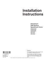
INSTALAR CAJA DE CONEXIONES
El conducto se encuentra en la parte superior derecha en
la parte posterior del horno.
Ubique e instale la caja de conexiones al alcance del
conducto del horno.
A través de los lados izquierdo o derecho de la pared del
gabinete y en el gabinete adyacente.
• O bien, a través del piso recortado.
• O bien, en el armario superior.
altura de
corte
REQUISITOS ELÉCTRICOS
Instalación única de advantium
La calificación del producto es 120/208 o 120/240 voltios, 60 hz,
30 Amperios. Este producto debe estar conectado a un circuito
de alimentación con el voltaje y la frecuencia adecuados y estar
protegido por un fusible de retardo de tiempo o un disyuntor.
La energía se debe suministrar desde un circuito derivado
separado de 30 amperios. El tamaño del cable debe cumplir
con los requisitos del código eléctrico nacional o el código local
vigente.
Instalación combinada de advantium y horno de pared
Cuando se instale en combinación con un horno de pared
simple, use cajas de conexiones eléctricas separadas.
Consulte las instrucciones de instalación del horno individual
para conocer los requisitos eléctricos de ese producto.
Estas conexiones deben ser realizadas por un electricista
calificado. Todas las conexiones eléctricas deben cumplir con el
código eléctrico nacional o los códigos locales vigentes.
Instalación combinada de cajones advantium y warming
Al instalar el horno advantium sobre un cajón de calentamiento
eléctrico, debe instalarse un receptáculo separado con conexión
a tierra de 120v, 60hz. Vea las instrucciones incluidas con el
cajón calentador.
ADVERTENCIA
El encendido eléctrico al circuito paralelo deberá estar
apagado mientras se realizan las conexiones de línea.
Use conductores de cobre únicamente.
Este electrodoméstico requiere que se realice una conexión
a tierra. El extremo libre del cable verde (cable a tierra)
debe estar conectado a una conexión a tierra adecuada.
Este cable debe permanecer conectado a la conexión a
tierra del horno.
Si la tubería de agua fría presenta interrupciones por
plásticos, juntas, conexiones de uniones u otros materiales
aislantes, NO use la misma como conexión a tierra.
NO se debe conectar a tierra en una tubería de suministro
de gas.
REQUISITOS ELÉCTRICOS (Cont)
NO posee un fusible en el circuito neutro o de conexión a
tierra. Un fusible en el circuito neutro o de conexión a tierra
podría ocasionar una descarga eléctrica.
Consulte a un electricista calificado o personal del servicio
si tiene dudas de que el electrodoméstico se encuentre
conectado a tierra apropiadamente.
Si no se siguen estas instrucciones, se podrán producir
lesiones graves o la muerte.
Preparación de la Instalación
INSTRUCCIONES DE CONEXIÓN A TIERRA
ADVERTENCIA
El uso inadecuado del enchufe de conexión a tierra puede provocar un riesgo de descarga
eléctrica.
Este electrodoméstico debe estar conectado a un sistema de
cableado de metal permanente con conexión a tierra o se debe
tender un conducto para la conexión a tierra del equipo con los
conductores del circuito y conectado al terminal de tierra del
equipo o al conductor de suministro del electrodoméstico.
31-7000080 Rev.2 5
PREPARACIÓN DE LA
ABERTURA
El Advantium 240V se puede instalar en combinación con
otros dispositivos integrados de Monogram. Siga siempre
las instrucciones de instalación de cada producto para
completar la instalación.
Instalación única de Advantium 240V:
Solicite un gabinete de un horno de 30 ”de ancho o corte la
abertura en una pared a las dimensiones que se muestran.
30”
23-1/2”
25-1/4”
17-1/2”
Construct
Base
Min. 3/8”
Plywood
Supported
by 2x4
or 2x2
Runners all
Four Sides
36-3/4”
Min.
Mantenga siempre una altura mínima de 36-3 / 4 ”desde
el piso hasta el recorte en cualquier instalación individual o
combinada.
• Deje los siguientes espacios libres alrededor de la
abertura sobre la superficie frontal del gabinete: 1 7/8”
desde la parte superior, 2 3/8” desde los extremos
laterales, y 1 1/8” desde la parte inferior.
(Nota: los
mismos se refieren a los espacios libres mínimos
requeridos para la instalación y no reflejan las
dimensiones reales del producto).
• Las superposiciones del horno ocultarán los bordes
cortados en todos los lados de la abertura.
Cuando se instale sobre un solo horno o un cajón
calentador, deje al menos 2 “entre las dos aberturas.
Esta separación proporcionará espacio libre para la
superposición de la parte inferior del Advantium 240V y las
otras superposiciones del dispositivo.
Construya un piso de horno sólido de 3/8 ”min. madera
contrachapada gruesa soportada por 2 x 4 o 2 x 2
corredores en todos los lados.
• El soporte debe estar nivelado y rígidamente montado, al
ras con el borde inferior del recorte.
PREPARACIÓN DE LA
ABERTURA
(CONT.)
Instalación sobre un Cajón para Calentar:
30”
23-1/2”
25-1/4”
17-1/2”
36-3/4”
Min.
2” Min.
(3”
recommended)
Per warming
drawer
requirement
Construct
Solid Bottom
Min. 3/8”
Plywood
Supported
by 2x4 or 2x2
Runners all
Four Sides
NOTA: Se podrán requerir despejes adicionales
entre los recortes. Asegúrese de que los soportes del
horno sobre la ubicación del Cajón para Calentar no
obstruyan la profundidad y altura internas requeridas.
Para más detalles, consulte las instrucciones de
instalación del Cajón para Calentar.
Preparación para la Instalación Estándar
IMPORTANTE: Mantenga siempre una altura mínima de 36-3 / 4 ”desde el piso hasta el recorte en cualquier
instalación individual o combinada.
6 31-7000080 Rev. 2
Preparación para la Instalación Estándar
IMPORTANTE: Mantenga siempre una altura mínima de 36-3 / 4 ”desde el piso hasta el recorte en cualquier
instalación individual o combinada.
PREPARACIÓN DE LA
ABERTURA
(CONT.)
Instalación sobre un horno de pared y un
cajón calentador:
NOTA: Se podrán requerir despejes adicionales
entre los recortes. Asegúrese de que los soportes del
horno sobre la ubicación del Cajón para Calentar no
obstruyan la profundidad y altura internas requeridas.
Para más detalles, consulte las instrucciones de
instalación del Cajón para Calentar.
PRECAUCIÓN
Por seguridad personal, la
superficie de montaje debe ser
capaz de soportar la carga del gabinete, además del
peso adicional del horno y el cajón, además de las
cargas adicionales del horno.
PREPARACIÓN DE LA
ABERTURA
(CONT.)
Instalación sobre un horno de pared:
* Si reemplazará un horno eléctrico doble por la
instalación combinada de un Advantium y un horno
simple, use las dimensiones mostradas. Es posible
que el riel intermedio que separa las dos aberturas
deba ser más largo que el de un mínimo de 2”
mostrado.
Construya un
fondo sólido,
sostenido por un
contrachapado
de un mínimo
de 3/8” sobre
los cuatro lados.
Deberá poder
sostener el peso
del horno y sus
contenidos.
30”
23-1/2”
25-1/4”
17-1/2”
Mín. de 2”
(3” Recomendado)
De Acuerdo con
los Requisitos del
Horno
45-1/4”
Mín. de 2”
(3” Recomendado)
De acuerdo con
los requisitos
sobre el Cajón
para Calentar
30”
23-1/2”
25-1/4”
17-1/2”
Mín. de 2”
(3” Recomendado)
Mín. de
45 ¼”
Construya un
fondo sólido,
sostenido por un
contrachapado de
un mínimo de 3/8”
sobre los cuatro
lados. Deberá
poder sostener el
peso del horno y
sus contenidos.
De Acuerdo con los
Requisitos del Horno
31-7000080 Rev.2 7
PREPARE EL INTERIOR
Corte e instale los ristreles laterales:
Corte los ristreles de madera laterales a la altura
de la abertura del gabinete y a aproximadamente 2
1/2” de profundidad. Instale, a cada lado, a Dim. E
desde la cara frontal del gabinete.
Corte e instale el ristrel inferior:
• Corte el ristrel de madera a una altura de 1 1/8”,
una profundidad del gabinete menos Dim. E y un
ancho de 25 ¼” para que coincida entre los ristreles
laterales. Instale en el piso del gabinete entre los
ristreles laterales, persione el mismo completamente
hacia atrás contra la pared del gabinete y asegúrese
de que su cara frontal se alinee con las caras
frontales de los ristreles laterales (brecha de Dim. E
desde la cara frontal del gabinete).
Preparación de la Instalación para el Montaje al Ras
(Monogram Únicamente)
A Profundidad de tacos
laterales y superiores
0tQGHƎ
B Altura del ristrel inferior 1-1/8”
C Profundidad del ristrel
inferior
Profundidad del gabinete
menos 1 3/8”
D Ancho del ristrel inferior 25-1/4”
E Los cuatro tacos de pro-
fundidad de inserción
ZSB9231NSS: 1-3/8”
ZSB9232NSS: 1-7/16”
VISTA
SUPERIOR
Cara Frontal del Gabinete
EE
A A
C
D
PREPARACIÓN DE LA
ABERTURA
El Advantium puede ser instalado junto con otros
electrodomésticos. Siempre siga las instrucciones de
instalación de cada producto, a fin de completar la
instalación.
Instalación Simple de Advantium
Corte la abertura en un gabinete siguiendo las
dimensiones mostradas.
• El soporte debe estar nivelado y montado de forma
rígida, al ras con el extremo inferior de la abertura.
**20-1/2”
Construya un
fondo sólido,
sostenido por un
contrachapado
de un mínimo
de 3/8” sobre
los cuatro lados.
Deberá poder
sostener el peso
del horno y sus
contenidos.
Mín. de
36 ¾”
F *
0tQGHƎ
Mín. de 2”
(3” Recomendado)
*Consulte la siguiente
tabla para conocer
las fugas deseadas a
los costados.
Especificaciones
por
electrodoméstico
Horno o
cajón para
calentar
Instalación al Ras Aprobada
Dimensión F
Fuga de 1/8” Fuga de 1/4”
Advantium Simple 30” 30-
1
/4
Sobre el Cajón para Calentar 30” 30-
1
/4
Sobre el Horno
30” 30-
1
/4
Sobre el Horno y el Cajón para
Calentar
30” 30-
1
/4
Sobre el Horno con Velocidad de
Cocción Incorporada
30” 30-
1
/4
** Las fugas superior e inferior están configuradas en
1/8”.
E
C
B
D
A
A
8 31-7000080 Rev. 2
Preparación de la Instalación
MONTAJE ESTÁNDAR
30Ǝ
23-1/2Ǝ
Mín. de
25-1/4Ǝ
21Ǝ
36-3/4Ǝ
Min.
Construya un
fondo sólido,
sostenido por un
contrachapado de
un mínimo de 3/8”
sobre los cuatro
lados. Deberá
poder sostener el
peso del horno y
sus contenidos.
INSTALACIÓN DEL MONTAJE AL RAS
(Monogram únicamente)
23-1/2Ǝ
K*
24Ǝ
Mín. de
36-3/4Ǝ
Construya un
fondo sólido,
sostenido por un
contrachapado de
un mínimo de 3/8”
sobre los cuatro
lados. Deberá
poder sostener el
peso del horno y
sus contenidos.
PREPARACIÓN DE LA ABERTURA (cont.)
El Advantium puede ser instalado junto con otros electrodomésticos. Siempre siga las instrucciones de instalación
de cada producto, a fin de completar la instalación.
Instalación Simple de Advantium:
Ordene un gabinete para horno simple de 30” de ancho o recorte la abertura en una pared siguiendo las
dimensiones mostradas.
Para una instalación nivelada, coloque el ristrel inferior a una altura de ¾” cuando se instale sobre un cajón de
almacenamiento.
'HMHXQHVSDFLROLEUHGHí´HQORVODGRVXQHVSDFLROLEUHGHí´HQODSDUWHVXSHULRU\XQHVSDFLROLEUH
GHí´HQODSDUWHLQIHULRUGHODDEHUWXUDSDUDWRGRVORVPRGHORV
Las superposiciones del horno ocultarán los extremos cortantes sobre todos los costados de la abertura.
Cuando se instale sobre un horno simple o sobre un cajón para calentar, deje por lo menos 2” entre las dos
aberturas. Esta separación brindará espacio para la superposición inferior del Advantium y las superposiciones de
los demás electrodomésticos.
El soporte debe estar nivelado y montado de forma rígida, al ras con el extremo inferior de la abertura.
Dimensión Fuga de
1/8”
Fuga de
1/4”
K 30” 30-1/4”
*Consulte la siguiente tabla para conocer las
fugas deseadas a los costados.
Preparación con un cajón de almacenamiento de accesorios
Según sea necesario, consulte la Preparación para la instalación del montaje estándar O la Preparación para
la instalación del montaje empotrado para obtener detalles de configuración. Tenga en cuenta la altura de corte
modificada a continuación
31-7000080 Rev.2 9
Instrucciones de Instalación
1
RETIRE EL EMBALAJE Y LAS PIEZAS
• Retire todo el material de embalaje y la cinta.
• Ubique el paquete de piezas que contiene los tornillos
de montaje.
• Retire el horno del cartón. No levante la unidad de la
manija ni del conducto. Es necesario que el horno sea
levantado por dos personas.
• Abra la puerta y retire cualquier embalaje que haya
dentro del horno.
Owner’s
Manual
Manual del
Propietario
Instrucciones
de Instalación
Bandeja de Vidrio
bandeja de parrilla de
metal
Anillo del Plato Giratorio
estante
Guía de Cocción
Cooking
Guide
Bandejas de Metal
IMPORTANTE: Si instalará el Horno Advantium
con un cajón de almacenamiento de accesorios, lea las
instrucciones de ensamble del cajón de almacenamiento
para ensamblar los productos juntos, antes de proceder al
paso 2.
5 Tornillos del Mismo
Color
(4 requeridos, 1
adicional)
8 Tornillos de Latón para la
Moldura Inferior
(3 requeridos,
5 adicionales)
Ajuste inferior
Tornillos de cabeza plana
(4 adicionales)
10 31-7000080 Rev. 2
Instrucciones de Instalación
2
CONDUCTO DE LA RUTA A
TRAVÉS DEL RECORTE
PRECAUCIÓN
Se requieren dos personas para
levantar el horno en la abertura.
Sujete la parte inferior en la parte delantera y trasera.
Deseche la base de espuma. No use la manija ni el
conducto para levantar el horno. se producirá daño
Con horno delante de la abertura del armario:
Inserte el conducto en la abertura del gabinete. Conecte
el cableado del horno y el circuito derivado.
Levante el horno en la abertura mientras continúa
alimentando el conducto en la dirección de la caja de
conexiones instalada. Asegúrese de que el conducto no
quede atrapado entre la parte posterior del horno y la
pared del gabinete.
Deje el horno unos centímetros por delante del marco
frontal del gabinete. No empuje la unidad por completo
en el corte.
(Se muestra el horno sin el
cajón de almacenamiento
de accesorios).
ADVERTENCIA
Desconecte la alimentación de la caja de
conexiones antes de realizar la conexión eléctrica.
Se requiere conexión a tierra eléctrica en este
aparato.
No conecte el suministro eléctrico hasta que
el aparato esté conectado a tierra de forma
permanente.
2
CONDUCTO DE LA RUTA A
TRAVÉS DEL RECORTE
(CONT.)
Cuando se conecta a un circuito derivado de 3
conductores:
Conecte el cable rojo del horno al cable rojo del
circuito derivado.
Conecte el cable negro del horno al cable negro del
circuito derivado.
Conecte el cable de tierra verde del horno y el cable
blanco.
Para derivar circuito neutro (blanco o gris).
Cuando se conecta a un circuito derivado de 4
conductores:
Conecte el cable rojo del horno al cable rojo del
circuito derivado.
Conecte el cable negro del horno al cable negro del
circuito derivado.
Interrumpa la conexión entre el cable blanco del
horno y el cable de tierra verde del horno.
Conecte el cable blanco del horno al cable neutro del
circuito derivado (blanco o gris).
Conecte el cable de tierra verde del horno al cable de
tierra del circuito derivado (verde o cobre desnudo).
31-7000080 Rev.2 11
Instrucciones de Instalación
3
INSTALE LA MOLDURA
INFERIOR
NOTA:
Si instala el horno Advantium 240 con un
cajón de almacenamiento de accesorios, no se
requiere el adorno inferior. Continúe con el paso 4.
Alinee las lengüetas del borde inferior con las ranuras
en la parte inferior del horno.
Asegure la moldura inferior a la parte inferior del horno
utilizando 3 tornillos de latón proporcionados
4
INSTALACIÓN DE LOS
TORNILLOS DE MONTAJE
Deslice el horno por el resto del recorrido hasta la
abertura, de modo que las pestañas laterales y el
panel de control queden contra la estructura del
gabinete. Asegúrese de que el horno quede centrado
en la abertura.
Abra la puerta, coloque una bandeja giratoria en el
horno y asegúrese de que la misma quede nivelada
en la unidad.
Haga agujeros piloto a través de las pestañas
laterales.
Coloque los tornillos del mismo color en las pestañas
laterales. Se recomienda que los tornillos sean
ajustados de forma manual.
Si instalará el horno con un cajón de
almacenamiento de accesorios:
Abra el cajón.
Haga agujeros piloto a través de las pestañas
laterales.
Coloque los tornillos del mismo color en las pestañas
laterales. Se recomienda que los tornillos sean
ajustados de forma manual.
5
FINALIZACIÓN DE LA
INSTALACIÓN
Presione el encendido. La luz interna se deberá
encender cuando la puerta se abra.
Para acceder a instrucciones de uso, consulte el
Manual del Propietario.
12 31-7000080 Rev. 2
Notas
31-7000080 Rev.2 13
Notas
14 31-7000080 Rev. 2
31-7000080 Rev. 2
04-21 GEA
Printed in China
  • Page 1 1
  • Page 2 2
  • Page 3 3
  • Page 4 4
  • Page 5 5
  • Page 6 6
  • Page 7 7
  • Page 8 8
  • Page 9 9
  • Page 10 10
  • Page 11 11
  • Page 12 12
  • Page 13 13
  • Page 14 14
  • Page 15 15
  • Page 16 16
  • Page 17 17
  • Page 18 18
  • Page 19 19
  • Page 20 20
  • Page 21 21
  • Page 22 22
  • Page 23 23
  • Page 24 24
  • Page 25 25
  • Page 26 26
  • Page 27 27
  • Page 28 28

GE ZSB9231NSS Guía de instalación

Categoría
Cocinas
Tipo
Guía de instalación
Este manual también es adecuado para

En otros idiomas