
APPLICATIONS
METRA. The World’s best kits.
™
metraonline.com1-800-221-0932
© COPYRIGHT 2014 METRA ELECTRONICS CORPORATION
REV. 9/18/2014 INST99-6523
CAUTION: Metra recommends disconnecting the
negative battery terminal before beginning any
installation. All accessories, switches, and especially
air bag indicator lights must be plugged in before
reconnecting the battery or cycling the ignition.
NOTE: Refer to the instructions included with the
aftermarket radio.
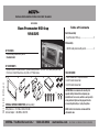
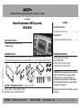
INSTALLATION INSTRUCTIONS FOR PART 99-6523
• ISO DIN radio provision with pocket
•
Custom texture
• A) Radio trim panel • B) Radio brackets • C) Radio mounting brackets • D) Pocket • E) (4) White plastic panel clips
• F) (4) 5mm x 12mm Phillips Screws • G) (2) #8 x 3/8” Phillips Screws
KIT FEATURES
KIT COMPONENTS
WIRING & ANTENNA CONNECTIONS (sold separately)
Wiring Harness: • 70-1784 or XSVI-6523-NAV
Antenna Adapter: • 40-VW10 or 40-EU10
• Panel removal tool • Phillips screwdriver
• 86-5618 radio removal tool
• 86-3528 radio removal tool
TOOLS REQUIRED
Ram Promaster 2014-up
99-6523
A
B C D E
Dash Disassembly
– Ram Promaster 2014-up ...................................... 2
Kit Assembly
– ISO DIN radio provision with pocket ...................... 3
Table of Contents
F G

99-6523
2
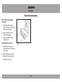
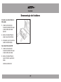
Dash Disassembly
With radio delete or Single DIN
factory radio:
1. Using Metra’s 86-5618 radio
removal tools pull the factory radio
from the dash. (Figure A)
2. Remove (2) Phillips screws in
bottom of dash opening.
3. Unclip and remove the factory
radio trim panel.
With Double Din factory radio:
1. Using Metra’s 86-3528 radio
removal tools pull the factory radio
from the dash.
2. Remove (2) Phillips screws from
the bottom of the dash opening.
Continue to kit assembly
(Figure A)

99-6523
3
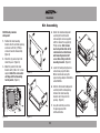
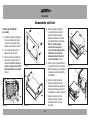
Kit Assembly
ISO DIN radio provision
with pocket
1. Position the radio mounting
brackets into the sub dash opening
and secure with the (2) Phillips
screws removed in disassembly.
(Figure A)
2. Attach the (4) panels clips to the
radio trim panel. (Figure B)
3. Mount the pocket to the radio
brackets with (2) #8 x 3/8” screws
supplied. Note: Pins on brackets
will align with front mounting
hole of pocket. (Figure C)
4. Attach the radio bracket/pocket
assembly to the aftermarket
radio using the screws supplied
with the radio or the supplied (4)
Phillips screws. Note: Screws
must not protrude from slot in
radio brackets as interference
with mounting bracket will
occur when sliding radio into
mounting brackets. (Figure D)
5. Locate the factory wiring harness
and antenna plug in the dash.
Metra recommends using the
proper mating adapters from Metra
and/or AXXESS.
6. Slide the aftermarket radio/pocket
assembly into the radio opening
between the radio mounting
brackets until it clips into the
opening. (Figure E)
7. Snap the radio trim panel into
the opening around the
aftermarket radio.
(Figure A)
(Figure C) (Figure E)
(Figure B) (Figure D)

METRA. The World’s best kits.
™
metraonline.com1-800-221-0932
© COPYRIGHT 2014 METRA ELECTRONICS CORPORATION
REV. 9/18/2014 INST99-6523
KNOWLEDGE IS POWER
Enhance your installation and fabrication skills by
enrolling in the most recognized and respected
mobile electronics school in our industry.
Log onto www.installerinstitute.com or call
800-354-6782 for more information and take steps
toward a better tomorrow.
Metra recommends MECP
certified technicians
INSTALLATION INSTRUCTIONS FOR PART 99-6523

INSTRUCCIONES DE INSTALACIÓN PARA LA PIEZA 99-6523
AplicAciones
METRA. The World’s best kits.
™
metraonline.com1-800-221-0932
© COPYRIGHT 2014 METRA ELECTRONICS CORPORATION
REV. 9/18/2014 INST99-6523
PRECAUCIÓN: Metra recomienda desconectar el terminal
negativo de la batería antes de comenzar cualquier
instalación. Todos los accesorios, interruptores y,
especialmente, las luces indicadoras de airbag deben
estar enchufados antes de volver a conectar la batería o
comenzar el ciclo de ignición.
Nota: Remítase a las instrucciones incluidas con el radio
de posventa.
Indice
• Herramienta para quitar paneles
• Destornillador Phillips
• 86-5618 Llave de remoción de radio
• 86-3528 Llave de remoción de radio
HerrAmientAs requeridAs
• Provisión de radio ISO DIN con cavidad
•
Textura especial
• A) Panel de moldura para radio • B) Soportes para radio • C) Soportes de montaje del radio • D) Cavidad
• E) (4) ganchos plásticos blancos para panel • F) (4) tornillos Phillips 5mm x 12mm • G) (2) tornillos Phillips #8 de 3/8”
cArActerísticAs del kit
componentes del kit
cABleAdo Y coneXiones de AntenA (se venden por separado)
Arnés de cables: • 70-1784 o XSVI-6523-NAV
Adaptador de antena: • 40-VW10 o 40-EU10
Desmontaje del tablero
– Ram Promaster 2014 y mas ................................. 2
Ensamble del kit
– Provisión de radio ISO DIN con cavidad .................. 3
Ram Promaster 2014 y mas
99-6523
A
B C D E
F G

99-6523
Desmontaje del tablero
2
Sin radio o con radio de fábrica de
DIN sencillo:
1. Usando las herramientas de
remoción del radio 86-5618 saque
el radio de fábrica del tablero.
(Figura A)
2. Quite los (2) tornillos Phillips de
abajo de la apertura del tablero.
3. Desenganche y quite el panel de la
moldura del radio de fábrica.
Con radio de fábrica doble DIN:
1. Usando las herramientas de
remoción del radio 86-3528 saque
el radio de fábrica del tablero.
2. Quite los (2) tornillos Phillips de
la parte inferior de la apertura del
tablero.
Continúe ensamble del kit
(Figura A)

99-6523
3
Ensamble del kit
Provisión de radio ISO DIN
con cavidad:
1. Posicione los soportes de montaje del
radio en la apertura del sub tablero
y sujete con los (2) tornillos Phillips
retirados al desensamblar. (Figura A)
2. Una los (4) ganchos de panel a la
moldura del radio. (Figura B)
3. Monte la cavidad en los soportes del
radio con los (2) tornillos #8 de 3/8”
suministrados. Nota: Los pins de los
soportes se alinearán con el orificio
de montaje delantero de la cavidad.
(Figura C)
4. Coloque el ensamble del soporte/
la cavidad del radio en el radio de
mercado secundario usando los
tornillos suministrados con el radio o
los (4) tornillos Phillips suministrados.
Nota: Los tornillos no deben
sobresalir de la ranura en los
soportes del radio, dado que habrá
interferencia con el soporte de
montaje al deslizar el radio en los
soportes de montaje. (Figura D)
5. Ubique el arnés de cableado de fábrica
y el conector de la antena en el tablero.
Metra recomienda que use adaptadores
adecuados de acoplamiento de Metra
y/o de AXXESS.
6. Deslice el ensamble de radio de
mercado secundario/cavidad en la
apertura del radio entre los soportes de
montaje del radio hasta que entre con
un chasquido en la apertura. (Figura E)
7. Coloque a presión el panel de la
moldura del radio en la apertura
alrededor del radio de mercado
secundario.
(Figura A)
(Figura C) (Figura E)
(Figura B) (Figura D)

INSTRUCCIONES DE INSTALACIÓN PARA LA PIEZA 99-6523
METRA. The World’s best kits.
™
metraonline.com1-800-221-0932
© COPYRIGHT 2014 METRA ELECTRONICS CORPORATION
REV. 9/18/2014 INST99-6523
KNOWLEDGE IS POWER
Enhance your installation and fabrication skills by
enrolling in the most recognized and respected
mobile electronics school in our industry.
Log onto www.installerinstitute.com or call
800-354-6782 for more information and take steps
toward a better tomorrow.
Metra recomienda técnicos
con certificación del Programa
de Certificación en Electrónica
Móvil (Mobile Electronics
Certification Program, MECP).
EL CONOCIMIENTO ES PODER
Mejore sus habilidades de instalación y fabricación
inscribiéndose en la escuela de dispositivos electrónicos
móviles más reconocida y respetada de nuestra industria.
Regístrese en www.installerinstitute.com o llame al
800-354-6782 para obtener más información y avance
hacia un futuro mejor.
Transcripción de documentos
INSTALLATION INSTRUCTIONS FOR PART 99-6523 APPLICATIONS Table of Contents Ram Promaster 2014-up 99-6523 Dash Disassembly – Ram Promaster 2014-up ...................................... 2 Kit Assembly – ISO DIN radio provision with pocket...................... 3 KIT FEATURES • ISO DIN radio provision with pocket • Custom texture KIT COMPONENTS • A) Radio trim panel • B) Radio brackets • C) Radio mounting brackets • D) Pocket • E) (4) White plastic panel clips • F) (4) 5mm x 12mm Phillips Screws • G) (2) #8 x 3/8” Phillips Screws REV. 9/18/2014 INST99-6523 A B C D F WIRING & ANTENNA CONNECTIONS (sold separately) Wiring Harness: • 70-1784 or XSVI-6523-NAV Antenna Adapter: • 40-VW10 or 40-EU10 METRA. The World’s best kits.™ E G TOOLS REQUIRED • Panel removal tool • Phillips screwdriver • 86-5618 radio removal tool • 86-3528 radio removal tool CAUTION: Metra recommends disconnecting the negative battery terminal before beginning any installation. All accessories, switches, and especially air bag indicator lights must be plugged in before reconnecting the battery or cycling the ignition. NOTE: Refer to the instructions included with the aftermarket radio. 1-800-221-0932 metraonline.com © COPYRIGHT 2014 METRA ELECTRONICS CORPORATION 99-6523 Dash Disassembly With radio delete or Single DIN factory radio: 1. Using Metra’s 86-5618 radio removal tools pull the factory radio from the dash. (Figure A) 2. Remove (2) Phillips screws in bottom of dash opening. 3. Unclip and remove the factory radio trim panel. With Double Din factory radio: (Figure A) 1. Using Metra’s 86-3528 radio removal tools pull the factory radio from the dash. 2. Remove (2) Phillips screws from the bottom of the dash opening. Continue to kit assembly 2 99-6523 Kit Assembly ISO DIN radio provision with pocket 4. Attach the radio bracket/pocket assembly to the aftermarket radio using the screws supplied with the radio or the supplied (4) Phillips screws. Note: Screws must not protrude from slot in radio brackets as interference with mounting bracket will occur when sliding radio into mounting brackets. (Figure D) 1. Position the radio mounting brackets into the sub dash opening and secure with the (2) Phillips screws removed in disassembly. (Figure A) 2. Attach the (4) panels clips to the radio trim panel. (Figure B) 3. Mount the pocket to the radio brackets with (2) #8 x 3/8” screws supplied. Note: Pins on brackets will align with front mounting hole of pocket. (Figure C) 5. Locate the factory wiring harness and antenna plug in the dash. Metra recommends using the proper mating adapters from Metra and/or AXXESS. (Figure B) (Figure D) 6. Slide the aftermarket radio/pocket assembly into the radio opening between the radio mounting brackets until it clips into the opening. (Figure E) 7. Snap the radio trim panel into the opening around the aftermarket radio. (Figure A) (Figure C) (Figure E) 3 INSTALLATION INSTRUCTIONS FOR PART 99-6523 KNOWLEDGE IS POWER REV. 9/18/2014 INST99-6523 Enhance your installation and fabrication skills by enrolling in the most recognized and respected mobile electronics school in our industry. Log onto www.installerinstitute.com or call 800-354-6782 for more information and take steps toward a better tomorrow. Metra recommends MECP certified technicians METRA. The World’s best kits.™ 1-800-221-0932 metraonline.com © COPYRIGHT 2014 METRA ELECTRONICS CORPORATION INSTRUCCIONES DE INSTALACIÓN PARA LA PIEZA 99-6523 AplicAciones Indice Ram Promaster 2014 y mas 99-6523 Desmontaje del tablero – Ram Promaster 2014 y mas ................................. 2 Ensamble del kit cArActerísticAs del kit • Provisión de radio ISO DIN con cavidad • Textura especial – Provisión de radio ISO DIN con cavidad .................. 3 componentes del kit • A) Panel de moldura para radio • B) Soportes para radio • C) Soportes de montaje del radio • D) Cavidad • E) (4) ganchos plásticos blancos para panel • F) (4) tornillos Phillips 5mm x 12mm • G) (2) tornillos Phillips #8 de 3/8” HerrAmientAs requeridAs • Herramienta para quitar paneles • Destornillador Phillips • 86-5618 Llave de remoción de radio • 86-3528 Llave de remoción de radio REV. 9/18/2014 INST99-6523 A B C D F cABleAdo Y coneXiones de AntenA (se venden por separado) Arnés de cables: • 70-1784 o XSVI-6523-NAV Adaptador de antena: • 40-VW10 o 40-EU10 METRA. The World’s best kits.™ 1-800-221-0932 E G PRECAUCIÓN: Metra recomienda desconectar el terminal negativo de la batería antes de comenzar cualquier instalación. Todos los accesorios, interruptores y, especialmente, las luces indicadoras de airbag deben estar enchufados antes de volver a conectar la batería o comenzar el ciclo de ignición. Nota: Remítase a las instrucciones incluidas con el radio de posventa. metraonline.com © COPYRIGHT 2014 METRA ELECTRONICS CORPORATION 99-6523 Desmontaje del tablero Sin radio o con radio de fábrica de DIN sencillo: 1. Usando las herramientas de remoción del radio 86-5618 saque el radio de fábrica del tablero. (Figura A) 2. Quite los (2) tornillos Phillips de abajo de la apertura del tablero. 3. Desenganche y quite el panel de la moldura del radio de fábrica. Con radio de fábrica doble DIN: (Figura A) 1. Usando las herramientas de remoción del radio 86-3528 saque el radio de fábrica del tablero. 2. Quite los (2) tornillos Phillips de la parte inferior de la apertura del tablero. Continúe ensamble del kit 2 99-6523 Ensamble del kit Provisión de radio ISO DIN con cavidad: 4. Coloque el ensamble del soporte/ la cavidad del radio en el radio de mercado secundario usando los tornillos suministrados con el radio o los (4) tornillos Phillips suministrados. Nota: Los tornillos no deben sobresalir de la ranura en los soportes del radio, dado que habrá interferencia con el soporte de montaje al deslizar el radio en los soportes de montaje. (Figura D) 1. Posicione los soportes de montaje del radio en la apertura del sub tablero y sujete con los (2) tornillos Phillips retirados al desensamblar. (Figura A) 2. Una los (4) ganchos de panel a la moldura del radio. (Figura B) 3. Monte la cavidad en los soportes del radio con los (2) tornillos #8 de 3/8” suministrados. Nota: Los pins de los soportes se alinearán con el orificio de montaje delantero de la cavidad. (Figura C) 5. Ubique el arnés de cableado de fábrica y el conector de la antena en el tablero. Metra recomienda que use adaptadores adecuados de acoplamiento de Metra y/o de AXXESS. (Figura B) (Figura D) 6. Deslice el ensamble de radio de mercado secundario/cavidad en la apertura del radio entre los soportes de montaje del radio hasta que entre con un chasquido en la apertura. (Figura E) (Figura A) 7. Coloque a presión el panel de la moldura del radio en la apertura alrededor del radio de mercado secundario. (Figura C) 3 (Figura E) INSTRUCCIONES DE INSTALACIÓN PARA LA PIEZA 99-6523 EL CONOCIMIENTO ESOWER PODER K NOWLEDGE IS P Mejore sus habilidades de instalación y fabricación REV. 9/18/2014 INST99-6523 Enhance your installation and fabrication skills by enrolling in the en most recognized and respected inscribiéndose la escuela de dispositivos electrónicos mobile school in our industry. móvileselectronics más reconocida y respetada de nuestra industria. Log onto www.installerinstitute.com or call Regístrese en www.installerinstitute.com o llame al 800-354-6782 for more information and take steps 800-354-6782 para obtener más información y avance toward a better tomorrow. hacia un futuro mejor. Metra recomienda técnicos con certificación del Programa de Certificación en Electrónica Móvil (Mobile Electronics Certification Program, MECP). METRA. The World’s best kits.™ 1-800-221-0932 metraonline.com © COPYRIGHT 2014 METRA ELECTRONICS CORPORATION-
 1
1
-
 2
2
-
 3
3
-
 4
4
-
 5
5
-
 6
6
-
 7
7
-
 8
8


Artículos relacionados
-
Metra 99-5830B Guía de instalación
-
Metra 99-7360B Guía de instalación
-
Metra 99-7359B Guía de instalación
-
-
-
Metra Electronics 99-5831G Manual de usuario
-
Metra 99-8721B Instrucciones de operación
-
-
-


