
1) TURN OFF POWER.
IMPORTANT: Before you start, NEVER attempt any work
without shutting off the electricity until the work is done.
a) Go to the main fuse, or circuit breaker, box in your
home. Place the main power switch in the “OFF” position.
b) Unscrew the fuse(s), or switch “OFF” the circuit breaker
switch(s), that control the power to the fixture or room
that you are working on.
c) Place the wall switch in the “OFF” position. If the fixture
to be replaced has a switch or pull chain, place those in
the “OFF” position.
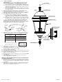
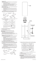
2) Find the appropriate threaded holes on mounting strap.
Assemble mounting screws into threaded holes.
3) Attach mounting strap to outlet box. (Screws not provided).
Mounting strap can be adjusted to suit position of fixture.
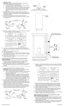
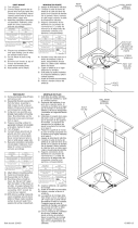
4) Grounding instructions: (See Illus. A or B).
A) On fixtures where mounting strap is provided with a
hole and two raised dimples. Wrap ground wire from
outlet box around green ground screw, and thread into
hole.
B) On fixtures where a cupped washer is provided. Attach
ground wire from outlet box under cupped washer and
green ground screw, and thread into mounting strap.
If fixture is provided with ground wire. Connect fixture
ground wire to outlet box ground wire with wire connector.
(Not provided.) After following the above steps. Never connect
ground wire to black or white power supply wires.
5) Make wire connections (connectors not provided.) Reference
chart below for correct connections and wire accordingly.
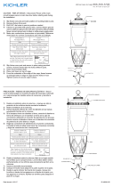
6) Push fixture to wall, carefully passing mounting screws
through holes in canopy.
7) Thread threaded balls onto mounting screws. Tighten
threaded balls to secure fixture to wall.
8) Insert recommended bulb.
9) Set roof down on top of fixture cage. Pass holes in roof over
threaded studs on top of cage.
10) Thread threaded balls onto threaded studs. Tighten threaded
balls to secure roof in place.
11) Thread top finial onto threaded pipe on top of roof. (DO NOT
over tighten.)
12) Thread bottom finial onto threaded pipe on bottom of
fixture. (DO NOT over tighten.)
INSTRUCTIONS FOR MOUNTING FIXTURE OUTDOORS AND/
OR IN WET LOCATIONS.
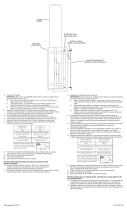
13) Mounting surface should be clean, dry, flat and 1/4” larger
that the canopy on all sides. Any gaps between the mounting
surface and canopy exceeding 3/16” should be corrected
as required.
14) With silicone caulking compound, caulk completely around
where back of canopy meets the wall surface to prevent
water from seeping into outlet box.
Connect Black or
Red Supply Wire to:
Connect
White Supply Wire to:
Black White
*Parallel cord (round & smooth) *Parallel cord (square & ridged)
Clear, Brown, Gold or Black
without tracer
Clear, Brown, Gold or Black
with tracer
Insulated wire (other than green)
with copper conductor
Insulated wire (other than green)
with silver conductor
*Note: When parallel wires (SPT I & SPT II)
are used. The neutral wire is square shaped
or ridged and the other wire will be round in
shape or smooth (see illus.)
Neutral Wire
Date Issued: 4/19/13 IS-9654-US
GREEN GROUND
SCREW
CUPPED
WASHER
A
B
OUTLET BOX
GROUND
FIXTURE
GROUND
DIMPLES
WIRE CONNECTOR
(NOT PROVIDED)
OUTLET BOX
GROUND
GREEN GROUND
SCREW
FIXTURE
GROUND
MOUNTING STRAP
PLANCHA PARA
MONTAR
THREADED BALL
BOLA ROSCADO
BOTTOM FINIAL
REMATE INFERIOR
THREADED PIPE
TUBO ROSCADO
THREADED STUD
ESPÁRRAGO ROSCADO
THREADED BALL
BOLA ROSCADO
ROOF
TECHO
TOP FINIAL
REMATE SUPERIOR
CAGE
JAULA

1) APAGAR LA ALIMENTACIÓN DE ENERGIE ELÈTRICA.
IMPORTANTE: Antes de comenzar, NUNCA trate de trabajar
sin antes desconectar la corriente hasta que el trabajo se
termine.
a) Vaya a la caja principal de fusibles, o interruptor o caja
de circuitos de su casa. Coloque el interruptor de la
corriente principal en posición de apagado “OFF”.
b) Desatornille el (los) fusible (s), o coloque el interruptor o
interruptores del breaker en posición de apagado
“OFF”, que controla (n) la corriente hacia el artefacto o
habitación donde está trabajando.
c) Coloque el interruptor de pared en posición de apagado
“OFF”. Si el artefacto que se va a reemplazar tiene un
interruptor o cadena que se jala, colóquelos en la posición
de apagado “OFF”.
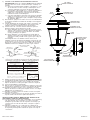
2) Encontrar los agujeros roscados correctos en la abrazadera
de montaje. Instalar los tornillos de montaje en los agujeros
roscados.
3) Unir la abrazadera de montaje a la caja de conexiones. (No
se proveen tornillos). La abrazadera de montaje puede
ajustarse para acomodar la posición del artefacto.
4) Instrucciones de conexión a tierra solamente para los
Estados Unidos. (Vea la ilustracion A o B).
A) En las lámparas que tienen el fleje, de montaje con un
agujero y dos hoyuelos realzados. Enrollar el alambre a
tierra de la caja tomacorriente alrededor del tornillo
verde y pasarlo por el aquiero.
B) En las lámparas con una arandela acopada. Fijar el
alambre a tierra de la caja tomacorriente del ajo de la
arandela acoada y tornillo verde, y paser por el fleje de
montaje.
Si la lámpara viene con alambre a tierra. Conecter el
alambre a tierra de la lámpara al alambre a tierra de la caja
tomacorriente con un conector de alambres. (No incluido)
Espués de seguir los pasos anteriores. Nunca conectar el
alambra a tierra a los alambres eléctros negro o blanco.
5) Haga les conexiones de los alambres (no se proveen los
connectores.) La tabla de referencia de abajo indica las
conexiones correctas y los alambres correspondientes.
6) Empuje el artefacto hacia a la pared, pasando cuidadosamente
los tornillos de montaje a través de los orificios en el escudete.
7) Atornille las bolas roscados en los tornillos de montaje.
Apriete las bolas roscados para fijar el artefacto al pared.
8) Inserte la bombilla recomendada.
9) Baje el techo en el artefacto. Pasando los agujeros en el techo
encima de los espárragos roscados, en el superior del artefacto.
10) Atornille las bolas roscados en los espárragos roscados.
Apriete las bolas roscados para sujetar el techo en el lugar.
(NO apriete excesivamente.)
11) Atornille el remate superior en el tubo roscado en la parte
superior de la techo.
12) Atornille el remate inferior en el extremo del tubo roscado en
la parte inferior del artefacto. (NO sobreapriete.)
INSTRUCCIONES PARA EL MONTAJE DEL ARTEFACTO AL
AIRE LIBRE Y/O EN UN LUGAR MOJADO.
13) La superficie de montaje debe estar limpia, seca, ser plana y
1/4” más grande que el esdudete en todos los bordes.
Cualquier espacio libre entre la superficie de montaje y el
escudete que exceda de 3/16” debe corregirse según se
requiera.
14) Calafatee totalmente con compuesto de calafatear de
silicona alrededor donde el escudete sienta en la superficie
de la pared para impedir la entrada de agua en la caja de
conexiones.
Date Issued: 4/19/13 IS-9654-US
MOUNTING STRAP
PLANCHA PARA
MONTAR
THREADED BALL
BOLA ROSCADO
Conectar el alambre de
suministro negro o rojo al
Conectar el alambre de
suministro blanco al
Negro Blanco
*Cordon paralelo (redondo y liso)
*Cordon paralelo (cuadrado y estriado)
Claro, marrón, amarillio o negro
sin hebra identificadora
Claro, marrón, amarillio o negro
con hebra identificadora
Alambre aislado (diferente del verde)
con conductor de cobre
Alambre aislado (diferente del
verde) con conductor de plata
*Nota: Cuando se utiliza alambre paralelo
(SPT I y SPT II). El alambre neutro es de forma
cuadrada o estriada y el otro alambre será de
forma redonda o lisa. (Vea la ilustracíón).
Hilo Neutral
ARANDELA
CONCAVA
A
B
TIERRA DE LA
CAJA DE SALIDA
TORNILLO DE TIERRA,
VERDE
DEPRESIONES
TIERRA
ARTEFACTO
CONECTOR DE ALAMBRE
(NO SE PROVEE)
TIERRA DE LA
CAJA DE SALIDA
TORNILLO DE TIERRA,
VERDE
TIERRA
ARTEFACTO
BOTTOM FINIAL
REMATE INFERIOR
THREADED PIPE
TUBO ROSCADO
THREADED STUD
ESPÁRRAGO ROSCADO
THREADED BALL
BOLA ROSCADO
ROOF
TECHO
TOP FINIAL
REMATE SUPERIOR
CAGE
JAULA

1) TURN OFF POWER.
IMPORTANT: Before you start, NEVER attempt any work
without shutting off the electricity until the work is done.
a) Go to the main fuse, or circuit breaker, box in your
home. Place the main power switch in the “OFF”
position.
b) Unscrew the fuse(s), or switch “OFF” the circuit breaker
switch(s), that control the power to the fixture or room that
you are working on.
c) Place the wall switch in the “OFF” position. If the fixture
to be replaced has a switch or pull chain, place those in
the “OFF” position.
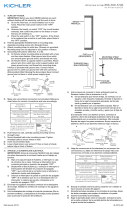
2) Find the appropriate threaded holes on mounting strap.
Assemble mounting screws into threaded holes.
3) Attach mounting strap to outlet box. (Screws not provided).
Mounting strap can be adjusted to suit position of fixture.
4) Make wire connections (connectors not provided.) Reference
chart below for correct connections and wire accordingly.
5) Push fixture to wall, carefully passing mounting screws
through holes in canopy.
6) Thread threaded balls onto mounting screws. Tighten
threaded balls to secure fixture to wall.
7) Insert recommended bulb.
8) Set roof down on top of fixture cage. Pass holes in roof over
threaded studs on top of cage.
9) Thread threaded balls onto threaded studs. Tighten threaded
balls to secure roof in place.
10) Thread top finial onto threaded pipe on top of roof. (DO NOT
over tighten.)
11) Thread bottom finial onto threaded pipe on bottom of
fixture. (DO NOT over tighten.)
INSTRUCTIONS FOR MOUNTING FIXTURE OUTDOORS AND/
OR IN WET LOCATIONS.
12) Mounting surface should be clean, dry, flat and 1/4” larger
that the canopy on all sides. Any gaps between the mounting
surface and canopy exceeding 3/16” should be corrected
as required.
13) With silicone caulking compound, caulk completely around
where back of canopy meets the wall surface to prevent
water from seeping into outlet box.
1) COUPER L’ALIMENTATION SECTEUR.
IMPORTANT: TOUJOURS couper l’électricité avant de
commencer le travail.
a) Localiser le coffret à fusibles ou le disjoncteur du
domicile. Mettre l’interrupteur principal en position
d’Arrêt.
b) Dévisser le ou les fusibles (ou mettre le disjoncteur sur
Arrêt) qui contrôlent l’alimentation vers le luminaire ou la
pièce dans laquelle le travail est effectué.
c) Mettre l’interrupteur mural en position d’Arrêt. Si le luminaire
à remplacer est doté d’un interrupteur ou d’une chaîne
connectée à l‘interrupteur, placer ces éléments en
position d’Arrêt.
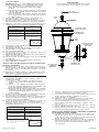
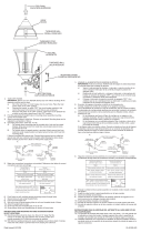
2) Trouver les trous filetés appropriés sur la barrette de montage.
Vissez les vis de montage dans les trous filetés.
3) Visser la barrette de montage à la boite de jonction. (Vis non
fournies). La barrette de montage peut etre ajustée pour
convenir à la position de l’applique.
4) Connecter les fils (connecteurs non fournis). Se reporter au
tableau ci-dessous pour faire les connexions. Plaquer
l’applique contre le mur, en passant soigneusement les vis
de montage dans les trous.
Connect Black or
Red Supply Wire to:
Connect
White Supply Wire to:
Black White
*Parallel cord (round & smooth) *Parallel cord (square & ridged)
Clear, Brown, Gold or Black
without tracer
Clear, Brown, Gold or Black
with tracer
Insulated wire (other than green)
with copper conductor
Insulated wire (other than green)
with silver conductor
*Note: When parallel wires (SPT I & SPT II)
are used. The neutral wire is square shaped
or ridged and the other wire will be round in
shape or smooth (see illus.)
Neutral Wire
Date Issued: 4/19/13 IS-9654-CB
MOUNTING STRAP
BARRETTE DE
MONTAGE
INSTRUCTIONS
For Assembling and Installing Fixtures in Canada
Pour L’assemblage et L’installation Au Canada
THREADED BALL
BOULE FILETÉ
5) Pousser le luminaire vers le mur en passant soigneusement
les vis de montage par les trous dans le cache..
6) Visser les boules filetées sur les vis de fixation. Resserrer les
boules filetées pour fixer le luminaire au plafond.
7) Insérez la lampe recommandée.
8) Abaisser le toit sur le luminaire. Passant les trous dans le
toit sur les goujons filetés du supérieur de la cage.
9) Visser les boules filetées sur les goujons filetés. Serrez les
boules filetées pour fixer le toit en place. (NE PAS serrer
avec excès).
10) Vissez l’ornement supérieure sur le tube fileté sur le dessus
du toit. (NE PAS serrer avec excès).
11) Vissez l’ornement inférieure sur le tube fileté sur l’extrémité
inférieure du luminaire. (NE PAS serrer avec excès).
INSTRUCTIONS DE MONTAGE DE LUMINAIRE À L’EXTÉRIEUR
ET/OU DANS DES LIEUX HUMIDES.
12) La surface de montage doit être propre, sèche, plate et de
0,6 cm plus épaisse que le cache sur tous les côtés. Tout
écart entre la surface de montage et le cache dépassant de
0,5 cm doit être rectifié selon les besoins.
13) À l’aide de matériaux d’étanchéité à la silicone, calfeutrer
bien autour où l’arrière du cache entre en contact avec le
mur pour empêcher l’eau de passer dans la boîte de
raccordement.
Connecter le fil noir ou
rouge de la boite
Connecter le fil blanc de la boîte
A Noir A Blanc
*Au cordon parallèle (rond et lisse)
*Au cordon parallele (à angles droits el strié)
Au bransparent, doré, marron, ou
noir sans fil distinctif
Au transparent, doré, marron, ou
noir avec un til distinctif
Fil isolé (sauf fil vert) avec
conducteur en cuivre
Fil isolé (sauf fil vert) avec
conducteur en argent
*Remarque: Avec emploi d’un fil paralléle
(SPT I et SPT II). Le fil neutre est á angles
droits ou strié et l’autre fil doit étre rond ou
lisse (Voir le schéma).
Fil Neutre
BOTTOM FINIAL
ORNEMENT
INFÉRIEURE
THREADED PIPE
TUBE FILETÉ
THREADED STUD
GOUJON FILETÉ
THREADED BALL
BOULE FILETÉ
ROOF
TOIT
TOP FINIAL
ORNEMENT SUPÉRIEURE
CAGE
CAGE
-
 1
1
-
 2
2
-
 3
3


Kichler Lighting 9654BK Manual de usuario
- Tipo
- Manual de usuario
- Este manual también es adecuado para
En otros idiomas
- français: Kichler Lighting 9654BK Manuel utilisateur
- English: Kichler Lighting 9654BK User manual
Documentos relacionados
-
Kichler Lighting 9707BK Manual de usuario
-
 Kichler Lighting 49122AVI Manual de usuario
-
 Kichler Lighting 49119AVI Manual de usuario
-
 Kichler Lighting 49476RZ Manual de usuario
-
 Kichler Lighting 43716PN Manual de usuario
-
 Kichler Lighting 49185BK Manual de usuario
-
Kichler Lighting 9956BK Manual de usuario
-
 Kichler Lighting 49849BKT Manual de usuario
-
 Kichler Lighting 9953CV Manual de usuario
-
Kichler Lighting 11077BKT Manual de usuario


