Signature Kitchen Suite SKSPH4802S Guía de instalación
- Categoría
- Campanas de cocina
- Tipo
- Guía de instalación
Este manual también es adecuado para

ENGLISH ESPAÑOL
MFL70208703_01
INSTALLATION GUIDE
HOOD
Read these instructions thoroughly before installing and operating the
hood.
www.signaturekitchensuite.com
SKSPH3602S
SKSPH4802S
Copyright © 2017 - 2018 Signature Kitchen Suite. All Rights Reserved.

2TABLE OF CONTENTS
TABLE OF CONTENTS
3 BEFORE YOU BEGIN
4 IMPORTANT SAFETY
INSTRUCTIONS
7 PRODUCT SPECIFICATIONS
7 General Specifications
8 Dimensions
9 PRODUCT OVERVIEW
9 Parts
9 Accessories
10 PLANNING THE INSTALLATION
10 Cabinet Layout
11 Ducting Options
12 Ducting Calculation Sheet
13 Power Supply
13 Verify the Package Contents
14 INSTALLATION INSTRUCTIONS
14 Rotating the Blower
16 Mounting the Range Hood
17 WIRING DIAGRAM

3
BEFORE YOU BEGIN
ENGLISH
BEFORE YOU BEGIN
IMPORTANT:
%Installer: In the interest of safety and to minimize problems, read these installation
instructions completely and carefully before you begin the installation process. Leave
these installation instructions with the customer.
%Customer: Keep these installation instructions for future reference and the local electrical
inspector’s use.
APPLIANCE DATA PLATE
%The appliance data plate contains the model and serial number information and the
electrical requirements.
%It is located inside the hood behind the filters on the back side of the chassis.
Remove the filters to view it.
All specifications subject to change without notice. SIGNATURE KITCHEN SUITE
assumes no liability for changes to specifications.

4IMPORTANT SAFETY INSTRUCTIONS
IMPORTANT SAFETY INSTRUCTIONS
Read and follow all instructions when using the range to prevent the risk of fire, electric
shock, personal injury, or damage. This guide does not cover all possible conditions that
may occur. Always contact your service agent or manufacturer about problems that you do
not understand.
Download this owner's manual at: www.signaturekitchensuite.com
This is the safety alert symbol. This symbol alerts you to potential hazards that
can result in property damage and/or serious bodily harm or death.
All safety messages will follow the safety alert symbol and either the word
WARNING or CAUTION. These words mean:
WARNING - Indicates a hazardous situation which, if not avoided, could result
in death or serious injury.
CAUTION - Indicates a hazardous situation which, if not avoided, could result
in minor or moderate injury.
WARNING
%To avoid the possibility of explosion or fire, do not store or use combustible, flammable
or explosive vapors and liquids (such as gasoline) inside or in the vicinity of this or
any other appliance. Also keep items that could explode, such as aerosol cans away
from cooktop burners, ovens and range hoods. Do not store flammable or explosive
materials in adjacent cabinets or areas.
%If the information in this manual is not followed exactly, a fire or explosion may result
causing property damage, personal injury or death.
%Do not use an additional speed control device with this unit.
%To avoid motor bearing damage and noisy and/or unbalanced impellers, keep
drywall spray, construction dust, etc. off power unit.
%Your ventilator motor has a thermal overload which will automatically shut off
the motor if it becomes overheated. The motor will restart when it cools down. If
the motor continues to shut off and restart, have the product serviced.
%TO REDUCE THE RISK OF FIRE, ELECTRIC SHOCK, OR INJURY TO PERSONS,
OBSERVE THE FOLLOWING:
– Use this unit only in the manner intended by the manufacturer. If you have questions,
contact the manufacturer.
– Before servicing or cleaning unit, switch power off at service panel and lock the
electrical panel door to prevent power from being switched on accidentally. When the
electrical panel door cannot be locked, securely fasten a prominent warning device,
such as a tag, to the service panel.

5
IMPORTANT SAFETY INSTRUCTIONS
ENGLISH
WARNING
%TO REDUCE THE RISK OF FIRE, ELECTRIC SHOCK, OR INJURY TO PERSONS,
OBSERVE THE FOLLOWING:
– Installation work and electrical wiring must be done by qualified person(s) in
accordance with all applicable codes and standards, including fire-rated construction.
– Sufficient air is needed for proper combustion and exhausting of gases through the
flue(chimney) of fuel burning equipment to prevent back drafting. Follow the heating
equipment manufacturer’s guidelines and safety standards such as those published
by the National Fire Protection Association (NFPA), and the American Society for
Heating, Refrigeration and Air Conditioning Engineers (ASHRAE), and the local code
authorities.
– When cutting or drilling into wall or ceiling, do not damage electrical wiring and other
hidden utilities.
– Ducted fans must always be vented to the outdoors.
CAUTION
For general ventilating use only. Do not use to exhaust hazardous or explosive materials
and vapors.
GENERAL SAFETY PRECAUTIONS
To reduce the risk of fire, electric shock, serious injury or death when using the appliance,
follow basic safety precautions, including the following:
WARNING
%Do not install or operate this hood if it has been damaged, dropped, has damaged
electrical wires or is not working properly. If the product is damaged when received,
immediately contact the dealer or builder.
%This range hood must be installed and grounded by a qualified installer according to
these installation instructions.
%Install or locate this appliance only in accordance with these installation instructions
and the requirements specified by the manufacturer of the cooktop or range. Improper
installation, adjustment, alteration, service or maintenance can cause serious personal
injury or property damage.
%The customer should not install, repair or replace any part of the range hood unless
specifically recommended in the literature accompanying it. A qualified service
technician should perform all other service.
%Keep all packaging materials away from children. Plastic bags can cause suffocation.
%Do not use an extension cord or adapter plug with this appliance.
%The installer must show the customer the location of the fuse box or circuit breaker
panel box so that the customer knows where and how to turn the power off.
%Before installing or servicing the range hood, switch power off at the fuse box circuit
breaker and lock the electrical panel door to prevent power from being switched on
accidentally. When the electrical panel cannot be locked, securely fasten a prominent
warning device, such as a tag, to the electrical panel.
%Read the owner's manual completely before using the appliance. Clean the appliance
only as instructed in the owner's manual. Use only the cleaners specified.
%Do not tamper with the controls.

6IMPORTANT SAFETY INSTRUCTIONS
WARNING
%Never allow the filter(s) to become blocked or clogged. Do not allow foreign objects,
such as cigarettes or napkins, to be sucked into the hood.
%Clean the filter(s) and all grease-laden surfaces often to prevent grease fires and
maintain performance.
%If the cooktop and range hood are near a window, use an appropriate window
treatment. Avoid long drapes or other window coverings that could blow over the
cooktop and hood, resulting in a fire hazard.
%Always run the fan(s) whenever the cooktop is operating.
%Never leave the range or cooktop unattended when a burner (or element) is in use.
Boil-overs and greasy spills may smoke and/or ignite.
%Do not leave children alone or unattended in the area where the cooktop and range
hood are in use. Never allow children to sit or stand on an appliance. Do not let children
play with a range, cooktop or range hood. Do not store items of interest to children
above or around the cooktop, range or range hood.
%The minimum vertical distance between the cooktop surface and the exterior part of
the hood must be no less than 26" (66 cm). The vertical distance required may be
longer for the range or cooktop being used. Consult the range or cooktop installation
instructions for the minimum and maximum vertical distance from the appliance being
used.
%TO REDUCE THE RISK OF FIRE, USE ONLY METAL DUCT WORK.
READ AND SAVE THESE INSTRUCTIONS

7
PRODUCT SPECIFICATIONS
ENGLISH
PRODUCT SPECIFICATIONS
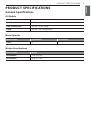
General Specifications
All Models
Fan Speeds 5
Filters Baffle type, dishwasher safe
Total Connect Load 120 VAC, 60 Hz, 4 Amp.
Lights 120 VAC, 8 W LED light strip
0RGHO6SHFL¿F
Model Number SKSPH4802S SKSPH3602S
Filters 43
:HLJKW6SHFL¿FDWLRQV
Model Number Weight
SKSPH4802S 71 lb. (32.5 kg)
SKSPH3602S 60 lb. (27.2 kg)

8PRODUCT SPECIFICATIONS
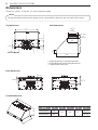
Dimensions
Tolerances: +1/16", -0 (1.6 mm, -0), unless otherwise stated.
NOTE
The exhaust duct(s) and electrical wiring can be connected from either the top or the back of the hood.
Top Dimensions Side Dimensions
2 5/8"
1 11/16"
8 9/16"
6 3/8"1 7/8"
E
D
**7 7/8"
or
***10 3/8"
**1 15/16"
or
***4 5/16"
12"
18"
24"
4"
* Single Blower Rect. Ducting Dimension
** Single Blower Round Ducting Dimension
*** Dual Blower Dimension
Back Dimensions
1 11/16"
9 1/8"
10 3/4"
Overall Dimensions
B
A
C
Model A B C D E
SKSPH4802S 48" 18" 24" 6" 45 7/8"
SKSPH3602S 36" 33 7/8"

9
PRODUCT OVERVIEW
ENGLISH
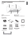
PRODUCT OVERVIEW
Parts
1
4 3
2
Accessories
Included Accessories
Manual
8" round collar Top cover plate 3 1/4"x10"
rectangular duct collar Manual
M6 x 1" (4) M6 x 1-1/2" (4) M6 x 2" (4) M3.5 x 8 (4)
3/16 x 3/8 (4) Wire Caps (3) Washers (4)
Optional Accessories
36", 48"
1
HOOD
2
ICON TOUCH CONTROL PANEL
3
LED STRIP LIGHT
4
BAFFLE FILTER
(SKSPH4802S: 4pcs, SKSPH3602S: 3pcs)

10 PLANNING THE INSTALLATION
PLANNING THE
INSTALLATION
WARNING
Observe all governing codes and ordinances
during planning and installation. Contact your
local building department for further information.
Use only duct work deemed acceptable by state,
municipal and local codes.
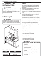
Cabinet Layout
WARNING
To reduce the risk of personal injury caused by
reaching over a hot appliance, cabinet storage
space located directly above the range should be
avoided.
36″
26″ min.
36″ max.
Minimum Cabinet Width
Models Width
SKSPH4802S 48" (121.9 cm)
SKSPH3602S 36" (91.5 cm)
Ducting
$PLQLPXPRI´URXQGRUƎ[ƎUHFWDQJXODU
duct must be used to maintain maximum air flow
efficiency for single blower and 10” round duct for
dual blower.
Always use rigid metal ducts only. Flexible ducts
could restrict air flow by up to 50%.
Also use calculation (on page 12) to compute total
available duct run when using elbows, transitions and
caps.
ALWAYS, when possible, reduce the number of
transitions and turns. If long duct run is required,
LQFUHDVHGXFWVL]HIURPƎWRƎ
If turns or transitions are required, install as far away
from hood duct output and as far apart as possible.
Minimum mount height between range top to hood
ERWWRPVKRXOGEHQROHVVWKDQƎ
Maximum mount height should be no higher than 36”.
It is important to install the hood at the proper
mounting height. Mounting the hood too low could
result in heat damage and fire hazard. Mounting the
hood too high will make it hard to reach and reduce
its performance and efficiency.
If available, also refer to the range manufacturer’s
height clearance requirements and recommended
hood mounting height above range.
Vertical Ducting:
%ƎURXQGPLQLPXPVLQJOHEORZHU
%ƎURXQGPLQLPXPGXDOEORZHU
Horizontal Ducting:
%Ǝ[ƎPLQLPXPVLQJOHEORZHU
%ƎURXQGPLQLPXPVLQJOHEORZHU
%ƎURXQGPLQLPXPGXDOEORZHU
CAUTION
DAMAGE DURING SHIPPING / INSTALLATION:
%Please fully inspect unit for damage before
installation.
%If the unit is damaged in shipment, return the
unit to the store in which it was bought for
repair or replacement.
%If the unit is damaged by the customer, repair
or replacement is the responsibility of the
customer.
%If the unit is damaged by the installer (if other
than the customer), repair or replacement must
be made by arrangement between customer
and installer.

11
PLANNING THE INSTALLATION
ENGLISH
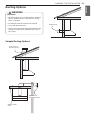
Ducting Options
WARNING
Fire Hazard
%NEVER exhaust air or terminate duct work into
spaces between walls, crawl spaces, ceiling,
attics or garages.
%All exhaust must be ducted to the outside.
%Use metal ductwork only.
%Fasten all connections with sheet metal screws
and tape all joints with certified Silver Tape or
Duct Tape.
Sample Ducting Options
Roof Pitch w/
Flashing & Cap
6RI¿WRUFUDZO
space
Side wall cap
w/ gravity damper
Rear Ducting

12 PLANNING THE INSTALLATION
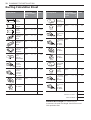
Ducting Calculation Sheet
Duct pieces
Equivalent
length x number
used =
Total
3-1/4" x 10"
Rect.,
straight
1 Ft. x ( ) = Ft.
6" Round,
straight 1 Ft. x ( ) = Ft.
7"-10"
Round,
straight
1 Ft. x ( ) = Ft.
3-1/4" x 10"
5HFWÛ
elbow
15 Ft. x ( ) = Ft.
3-1/4" x 10"
5HFWÛ
elbow
9 Ft. x ( ) = Ft.
3-1/4" x 10"
5HFWÛ
ÀDWHOERZ
24 Ft. x ( ) = Ft.
3-1/4" x 10"
Rect.
wall cap
with damper
30 Ft. x ( ) = Ft.
3-1/4" x 10"
Rect.to
6" round
transition
5 Ft. x ( ) = Ft.
3-1/4" x 10"
Rect.to
6" round
transition
ÛHOERZ
20 Ft. x ( ) = Ft.
6" Round,
ÛHOERZ 15 Ft. x ( ) = Ft.
6" Round,
ÛHOERZ 9 Ft. x ( ) = Ft.
Subtotal column 1 = Ft.
Duct pieces
Equivalent
length x number
used =
Total
6" Round
wall cap
with damper
30 Ft. x ( ) = Ft.
6" Round,
roof cap 30 Ft. x ( ) = Ft.
6" round to
3-1/4" x 10"
rect.
transition
1 Ft. x ( ) = Ft.
6" round to
3-1/4" x 10"
rect.
transition
ÛHOERZ
16 Ft. x ( ) = Ft.
7" - 10"
Round,
ÛHOERZ
15 Ft. x ( ) = Ft.
7" - 10"
Round,
ÛHOERZ
9 Ft. x ( ) = Ft.
7" - 10"
Round wall
cap with
damper
30 Ft. x ( ) = Ft.
7" - 10"
Round,
roof cap
30 Ft. x ( ) = Ft.
7" round to
3-1/4" x 10"
rect.
transition
8 Ft. x ( ) = Ft.
7" round to
3-1/4" x 10"
rect.
transition
ÛHOERZ
23 Ft. x ( ) = Ft.
Subtotal column 2 = Ft.
Subtotal column 1 = Ft.
Total ductwork = Ft.
Maximum Duct Length: For satisfactory air
movement, the total duct length should not exceed
100 equivalent feet.

13
PLANNING THE INSTALLATION
ENGLISH
Ductwork Design Tips
Wherever possible, reduce the number of transitions
and turns to as few sharp angles as possible. Two
staggered 45° angles are better than one 90°.
Keep turns as far away from the hood exhaust as
possible, and allow as much space between bends
as possible.
For best performance, use round ducts instead of
rectangular, especially when elbows are required.
If multiple elbows are used, try to keep a minimum of
24" of straight duct between them.
Avoid “S” or “back to back” use of adjacent elbows.
In regions where the weather gets extremely cold,
use thermal breaks, such as a short section of non-
metallic duct, to avoid indoor heat loss. Locate the
break as close as possible to the outside pass-
through point.
Do not use flexible metal duct.
Do not use ductwork that is smaller in cross-sectional
area than the recommended types above.
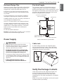
Power Supply
WARNING
%The information in this manual should be
followed exactly. Failure to do so could result
in fire or electrical shock, causing property
damage, personal injury or death.
%All electrical work must by performed by
qualified electrician or person with similar
technical knowledge and background.
%For personal safety, remove house fuse or open
circuit breaker before beginning installation. Do
not use extension cord or adapter plug with this
appliance.
%Follow national electrical codes or
prevailing local codes and ordinances.
Electrical Supply
This appliance requires a 120V 60Hz electrical
supply, and must be connected to an individual,
properly grounded branch circuit, protected by a 15 or
20 ampere circuit breaker or time delay fuse. Wiring
must be 2 wire w/ ground. Please also refer to the
Electrical Diagram label on product.
GREEN
WHITE
WHITE
BLACK
BLACK
GREEN
Wire cap,
3 places
Junction box
To house circuit breaker
panel or fuse box
UL/CSA approved
NEMA strain relief To range hood
3 Wire Connection to Junction Box
Cable Lock
A cable locking connector (not supplied) might
also be required by local codes. Check with local
requirements and codes, and purchase and install
appropriate connector if necessary.
Cable Lock
Verify the Package Contents
Unpack the parts box and verify that all parts and
accessories have been included. If any item is
missing or damaged, please contact the dealer
immediately. Do not install a damaged or incomplete
appliance.
Make sure you have everything necessary for proper
installation before proceeding.

14 INSTALLATION INSTRUCTIONS
INSTALLATION
INSTRUCTIONS
WARNING
%Do not install the range hood unless the
electrical service provided meets the range
hood specifications.
%Observe all governing codes and ordinances
during installation. Contact your local building
department for further information.
%A qualified technician must complete the
installation of this built-in appliance. More than
one person is required to raise the hood into
place. The owner is responsible to make sure
the hood is properly installed.
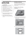
1Start by removing the baffle filters from the
bottom of the hood. Put them in a safe location
so that they will not be damaged.
2If the hood will be installed so that air will
exhaust out of the back, the blowers must be
rotated into the correct position before hanging
the hood.
Rotating the Blower
This range hood is equipped standard with a 8”
round vertical duct option. To convert from 8” round
vertical to 8” round horizontal ducting or 3-1/4” x 10”
rectangular horizontal ducting please following the
instructions below.
Vertical to Horizontal Ducting
Conversion
1Disconnect the blower plug.
2Remove the 4 screws on the interior of the hood
body which attach the single blower plate to the
top of the hood body. Remove the single blower
and blower plate.
3At the back, knock out plate B for rectangular
ducting, or plate C for 8-inch round ducting.
C
B

15
INSTALLATION INSTRUCTIONS
ENGLISH
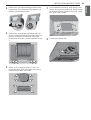
4Remove the 4 screws holding the blower to the
blower plate. Turn the blower 180 degrees and
reattach it to the blower plate.
5Position the single blower and blower plate as
shown, tucking the back of the blower plate into
the tabs at the back of the hood. Secure the
blower plate using the 4 screws removed in step
2.
6Attach an 8" round duct collar or 3 1/4" x 10"
rectancular duct collar to the back of the hood
body using four M3.5 x 8 screws.
7From inside the hood body, align the top cover
plate to the top of the hood body. Attach the top
cover plate from the outside of the hood, using
four 3/16" x 3/8" screws.
8Connect the blower plug.

16 INSTALLATION INSTRUCTIONS
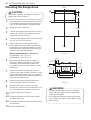
Mounting the Range Hood
CAUTION
%At least two installers are required due to the
weight and size of the hood.
1Select the preferred ducting application (vertical
or horizontal) and prepare the hood. Refer to
page 14 for single blower horizontal ducting.
2Plumb and mark center line.
3Choose the desired height above the cooking
surface (26" minimum). Level and mark the
hood bottom (line A in Fig. 1).
4Level and mark the top of the wood board (line
B in Fig. 1), 16 7/8" from line A.
5Draw a center line on the wood board as
shown. Align the center of the board with the
center line on the wall and align the top of the
board with line B. Attach the board to the wall
studs using four M6 wood screws.
Wood Board Dimensions : (W x D x H)
SKSPH3602S - 33" x 1/2" x 4"
SKSPH4802S - 45" x 1/2" x 4"
6Prepare the duct pipe and duct cutouts in
the upper cabinet if needed, or in the wall if
ducting the hood horizontally. Refer to the
hood specifications on page 8 for duct cutout
dimensions.
7Prepare the electrical wiring and electrical
cutouts in the upper cabinet if needed, or in the
wall if horizontal electrical hook up is required.
Refer to the hood specifications on page 8 for
electrical cutout dimensions.
8Mount the hood onto the wood board and
secure it using four M6 wood screws.
9Insert two M6 wood screws into the wall
through the screw holes in the lower body. See
Fig. 2 for dimensions between screw holes.
10 Install the electrical connection.
11 Install the ductwork and seal it with certified
aluminum duct tape.
12 Power up the hood and check for leaks around
the duct tape.
13 Install the baffle filters.
C/L
C/L
A
B
16 7/8"
min 26"
4"
wood board
FIG. 1
3 5/16"
21 1/4"
5 5/16"
16 7/8"
27 3/8" (36" & 42"),
35 1/4" (48" & 54")
1 11/16"
16 1/8"
13 5/8"
FIG. 2
WARNING
%Electrical wiring must be done by qualified
personnel in accordance with all applicable
codes and standards.
%This range hood must be properly grounded.
Turn off electrical power at main power supply
before wiring.

17
WIRING DIAGRAM
ENGLISH
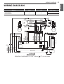
WIRING DIAGRAM
Models Volts HZ MAX Amps
SKSPH4802S
SKSPH3602S 120 60 Single Motor 4
Dual Motor 7
MOTOR
BLUE
BROWN
GRAY
AC N
TRANSFORMER
WHITE
GREEN
BLACK
WHITE
BODY
BLACK
REMARKS:CONDENSER 11+11uF 250VAC 2 FIT AC120V 60Hz
AC L
GRAY
BLUE
BROWN
GREEN
LO
MID
HI
YELLOW
YELLOW
YELLOW
YELLOW
COM
FUSE
YELLOW
RED
WHITE
MOTOR
GREEN
YELLOW
RED
WHITE
RED
RED
CONTROL PC
GRAY
BLUE
BROWN
Wi-Fi PCB
BLACK
WHITE
GREEN
Wi-Fi PCB

18 MEMO
MEMO

ESPAÑOL
MFL70208703_01
GUÍA DE INSTALACIÓN
CAMPANA
Lea atentamente estas instrucciones antes de instalar y poner la campana
en funcionamiento.
www.signaturekitchensuite.com
SKSPH3602S
SKSPH4802S
Copyright © 2017 - 2018 Signature Kitchen Suite. Todos los Derechos Reservados.

2ÍNDICE
ÍNDICE
3 ANTES DE COMENZAR
4 INSTRUCCIONES IMPORTANTES DE
SEGURIDAD
7 ESPECIFICACIONES DEL PRODUCTO
7 Especificaciones generales
8 Dimensiones
9 DESCRIPCIÓN GENERAL DEL
PRODUCTO
9 Piezas
9 Lista de piezas
10 PLANIFICACIÓN DE LA INSTALACIÓN
10 Disposición de alacenas
11 Opciones de conducto
12 Hoja de cálculo de conducto
13 Suministro de energía
13 Verifique el contenido del embalaje
14 INSTRUCCIONES DE INSTALACIÓN
14 Posicionamiento del extractor
16 Montaje de la campana extractora
17 DIAGRAMA DE CABLEADO

3
ANTES DE COMENZAR
ESPAÑOL
ANTES DE COMENZAR
IMPORTANTE:
%Instalador: Para preservar la seguridad y reducir los posibles problemas, lea estas instrucciones
para la instalación por completo antes de comenzar el proceso de instalación. Deje estas
instrucciones al cliente.
%Cliente: Conserve estas instrucciones de instalación para referencia futura y para que las consulte
el inspector
PLACA DE DATOS DEL ARTEFACTO
%La placa de datos de este artefacto contiene información del número de serie y el modelo, y los
requisitos eléctricos.
%Se encuentra ubicada dentro de la campana, detrás de los filtros, en la parte posterior del chasis.
Retire los filtros para verla.
Todas las especificaciones están sujetas a cambios sin previo aviso. SIGNATURE KITCHEN
SUITE no se hace responsable por cambios en las especificaciones.

4INSTRUCCIONES IMPORTANTES DE SEGURIDAD
INSTRUCCIONES IMPORTANTES DE
SEGURIDAD
Lea y siga todas las instrucciones cuando utilice la cocina para evitar riesgos de incendios, descargas
eléctricas, lesiones personales o daños. Esta guía no incluye todas las situaciones posibles que
podrían ocurrir. Siempre comuníquese con su agente de servicio técnico o con el fabricante cuando
haya problemas que no comprenda.
Descargue este manual en: www.signaturekitchensuite.com
Este es el símbolo de alerta de seguridad. Este símbolo le advierte sobre posibles riesgos
que pueden ocasionar daños materiales, lesiones personales graves o la muerte.
El símbolo de alerta de seguridad siempre estará acompañado de las palabras
"ADVERTENCIA" o "PRECAUCIÓN". Estos términos significan lo siguiente:
ADVERTENCIA
- Indica una situación peligrosa que, de no evitarse, podría
causar lesiones graves o la muerte.
PRECAUCIÓN
- Indica una situación peligrosa que, de no evitarse, podría
causar lesiones leves o moderadas.
ADVERTENCIA
%Para evitar que se produzcan explosiones o incendios, no almacene ni use líquidos o vapores
combustibles, inflamables o explosivos (como por ejemplo, gasolina) dentro o cerca de este o
cualquier otro artefacto. Además, mantenga cualquier artículo que pueda explotar, como, por
ejemplo, latas de aerosol, alejado de los quemadores de la cocina, del horno y de la campana
extractora. No almacene materiales explosivos o inflamables en áreas o alacenas cercanas.
%Si no sigue con exactitud la información de este manual, podrían producirse un incendio o
descarga eléctrica, daños a la propiedad, lesiones personales o la muerte.
%No utilice un dispositivo adicional de control de velocidad con esta unidad.
%Para evitar daños en los rodamientos del motor y rotores ruidosos y/o desequilibrados,
mantenga la unidad de potencia alejada de polvo de construcción, de yeso, etc.
%El motor del ventilador cuenta con una protección de sobrecarga térmica que apagará
automáticamente el motor en caso de que este se sobrecaliente. El motor volverá a
arrancar cuando se enfríe. Si el motor continúa apagándose y reiniciándose, se le debe
realizar mantenimiento al producto.
%PARA REDUCIR EL RIESGO DE INCENDIO, DESCARGAS ELÉCTRICAS O LESIONES
PERSONALES, TENGA EN CUENTA LO SIGUIENTE:
– Use esta unidad solamente del modo previsto por el fabricante. Si tiene alguna pregunta,
póngase en contacto con el fabricante.
– Antes de limpiar o realizarle mantenimiento a la unidad, apáguela desde el panel de servicio
y bloquee la puerta del panel eléctrico para evitar que la unidad se encienda por accidente.
En caso de que la puerta del panel eléctrico no se pueda bloquear, coloque un dispositivo de
advertencia bien visible y firmemente sujeto, como, por ejemplo, una etiqueta, en el panel de
servicio.

5
INSTRUCCIONES IMPORTANTES DE SEGURIDAD
ESPAÑOL
ADVERTENCIA
%PARA REDUCIR EL RIESGO DE INCENDIO, DESCARGAS ELÉCTRICAS O LESIONES
PERSONALES, TENGA EN CUENTA LO SIGUIENTE:
– El trabajo de instalación y el cableado eléctrico deben ser realizados por personal
calificado en conformidad con todos los códigos y las normas aplicables, incluso respecto a
construcciones a prueba de fuego.
– Se necesita aire suficiente para que la combustión y el escape de gases se realicen de
manera correcta a través del conducto (chimenea) del equipo que quema combustible a fin
de prevenir el tiro invertido. Siga las instrucciones del fabricante del equipo de calefacción
y las medidas de seguridad, tales como las publicadas por la Asociación Nacional de
Protección contra Incendios (NFPA, por sus siglas en inglés), la Sociedad Americana de
Aire Acondicionado, Refrigeración y Calefacción (ASHRAE, por sus siglas en inglés) y las
autoridades locales.
– Al cortar o perforar la pared o el cielorraso, no dañe el cableado eléctrico ni otros pasos de
servicios que estén ocultos.
– Los ventiladores con conductos siempre deben tener salida al exterior.
PRECAUCIÓN
Solo para uso de ventilación general. No lo utilice para la extracción de materiales y vapores
peligrosos o explosivos.
PRECAUCIONES GENERALES DE SEGURIDAD
Para reducir el riesgo de incendio, descargas eléctricas, lesiones graves o muerte al usar este equipo,
siga las precauciones de seguridad básicas, incluidas las siguientes:
ADVERTENCIA
%No instale ni utilice la campana si se ha dañado, caído, se han dañado los cables eléctricos o si
no está funcionando correctamente. Si el producto está dañado cuando lo recibe, póngase en
contacto inmediatamente con el distribuidor o constructor.
%Esta campana extractora debe ser instalada y conectada a tierra de acuerdo con las
instrucciones de instalación por un instalador calificado.
%Instale o coloque este aparato siguiendo solamente estas instrucciones de instalación y
los requisitos especificados por el fabricante de la cocina o de la superficie de cocción. La
instalación, los ajustes, las modificaciones, las reparaciones y el mantenimiento mal realizados
pueden causar lesiones personales graves o daños materiales.
%El cliente no debe instalar, reparar ni reemplazar ninguna pieza de la campana extractora, salvo
que esto se recomiende específicamente en la documentación suministrada. Toda otra tarea de
mantenimiento debe ser realizada por un técnico calificado.
%Mantenga todos los envoltorios alejados de los niños. Las bolsas plásticas pueden causar
asfixia.
%No use un cable de extensión ni un adaptador con este artefacto.
%El instalador debe mostrar al cliente la ubicación del panel de interruptores de circuitos o la caja
de fusibles para que el cliente sepa dónde y cómo cortar la energía.
%Antes de instalar o realizarle mantenimiento a la campana extractora, apáguela desde el
interruptor de circuitos de la caja de fusibles y bloquee la puerta del panel eléctrico para evitar
que la unidad se encienda por accidente. En caso de que el panel del panel eléctrico no se
pueda bloquear, coloque un dispositivo de advertencia bien visible y firmemente sujeto, como,
por ejemplo, una etiqueta, en el panel eléctrico.

6INSTRUCCIONES IMPORTANTES DE SEGURIDAD
ADVERTENCIA
%Lea el manual del propietario por completo antes de usar el aparato. Limpie el aparato
solamente como se indica en el manual del propietario. Use únicamente los productos de
limpieza especificados.
%No manipule indebidamente los controles.
%Nunca permita que el/los filtro(s) se bloquee(n) u obstruya(n). No permita que objetos extraños,
tales como cigarrillos o servilletas, sean aspirados por la campana.
%Limpie con frecuencia los filtros y todas las superficies que se cubren de grasa para evitar que
se produzcan incendios y para mantener el rendimiento.
%Si la cocina y la campana extractora se encuentran cerca de una ventana, asegúrese de que
la ventana cumpla con las condiciones adecuadas. Evite que la ventana tenga cortinas largas
u otras cubiertas que podrían volar sobre la superficie de cocción y la campana, ya que esto
puede significar un riesgo de incendio.
%Siempre ponga en funcionamiento el/los ventilador(es) cuando esté utilizando la superficie de
cocción.
%Nunca deje la cocina o la superficie de cocción sin vigilancia cuando un quemador (u hornalla)
esté siendo utilizado. Los derramamientos por ebullición o los derrames de grasa pueden emitir
humo y/o arder.
%No deje niños solos o sin vigilancia en el área donde se estén utilizando la superficie de cocción
y la campana extractora. Nunca permita que los niños se sienten en un artefacto o se suban a
él. No permita que los niños jueguen con una cocina, una superficie de cocción o una campana
extractora. No almacene artículos de interés para los niños encima o alrededor de la superficie
de cocción, la cocina o la campana extractora.
%La distancia vertical mínima entre la superficie de la cocina y la parte exterior de la campana no
debe ser menor de 26" (66 cm). La distancia vertical puede tener que ser mayor según la cocina
o la superficie de cocción que se esté utilizando. Consulte las instrucciones de instalación de la
cocina o la superficie de cocción para conocer la distancia mínima y máxima vertical desde el
artefacto que se utilice.
%PARA REDUCIR EL RIESGO DE INCENDIO, UTILICE SOLAMENTE CONDUCTOS DE METAL.
LEA Y GUARDE ESTAS INSTRUCCIONES

7
ESPECIFICACIONES DEL PRODUCTO
ESPAÑOL
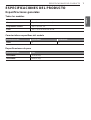
ESPECIFICACIONES DEL PRODUCTO
Especificaciones generales
Todos los modelos
Velocidades del ventilador 5
Filtros Tipo deflector, aptos para lavavajillas
Carga total de conexión 120 V CA, 60 Hz, 4 A.
Luces 120 V CA, tira de luces LED de 8 W
&DUDFWHUtVWLFDVHVSHFt¿FDVGHOPRGHOR
Número de modelo SKSPH4802S SKSPH3602S
Filtros 43
(VSHFL¿FDFLRQHVGHSHVR
Número de modelo Peso
SKSPH4802S 71 lb (32,5 kg)
SKSPH3602S 60 lb (27,2 kg)

8ESPECIFICACIONES DEL PRODUCTO
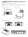
Dimensiones
Tolerancias: +1/16", -0 (1.6 mm, -0), a menos que se especifique lo contrario.
NOTA
El/los conducto(s) de escape y el cableado eléctrico se pueden conectar desde la parte superior o posterior de la
campana.
Dimensiones de la parte superior Dimensiones laterales
2
5
/
8
"
1
11
/
16
"
8
9
/
16
"
6
3
/
8
"
1
7
/
8
"
E
D
**7
7
/
8
"
or
***10
3
/
8
"
**1
15
/
16
"
o
***4
5
/
16
"
12"
18"
24"
4"
* Dimensión ventilador individual de rectangular
** Dimensión ventilador individual de redondo
*** Dimensión ventilador doble
Dimensiones de la parte posterior
1
11
/
16
"
9
1
/
8
"
10
3
/
4
"
Dimensiones generales
B
A
C
Modelo A B C D E
SKSPH4802S 48" 18" 24" 6" 45 7/8"
SKSPH3602S 36" 33 7/8"

9
DESCRIPCIÓN GENERAL DEL PRODUCTO
ESPAÑOL
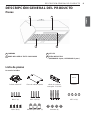
DESCRIPCIÓN GENERAL DEL PRODUCTO
Piezas
1
4 3
2
Lista de piezas
Accesorios incluidos
Manual
Collarín redondo 8" Placa de cubierta superior collarín de conducto
rectangular 3 1/4"x10" Manual
M6 x 1" (4) M6 x 1-1/2" (4) M6 x 2" (4) M3.5 x 8 (4)
3/16 x 3/8 (4) Remates para cables (3) Arandelas (4)
1 CAMPANA
2 PANEL DE CONTROL TÁCTIL CON ICONOS
3 LUZ LED
4 FILTRO DEFLECTOR
(SKSPH4802S: 4 pzas., SKSPH3602S: 3 pzas.)

10 PLANIFICACIÓN DE LA INSTALACIÓN
PLANIFICACIÓN DE LA
INSTALACIÓN
ADVERTENCIA
Respete todos los códigos y las ordenanzas vigentes
durante la planificación y la instalación. Póngase en
contacto con el departamento de construcción de
su localidad para obtener más información. Utilice
solamente conductos considerados aceptables por las
normas estatales, municipales y locales.
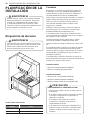
Disposición de alacenas
ADVERTENCIA
Para reducir el riesgo de daños personales causados
por estirar el cuerpo sobre un artefacto caliente, debe
evitarse usar el espacio de almacenamiento de la
alacena ubicada justo encima de la cocina.
36″
26″ min.
36″ max.
Ancho mínimo de la alacena
Modelos Ancho
SKSPH4802S 48" (121,9 cm)
SKSPH3602S 36" (91,5 cm)
Conducto
Debe usarse un conducto rectangular de un mínimo de
ƎUHGRQGRRƎ[ƎUHFWDQJXODUSDUDPDQWHQHUOD
máxima eficiencia de flujo de aire para un ventilador y un
FRQGXFWRUHGRQGRGHƎSDUDXQYHQWLODGRUGREOH
Utilice siempre conductos de metal solamente. Los conductos
flexibles podrían restringir el flujo de aire en hasta un 50 %.
Utilice un cálculo (en la página 12) para calcular el
conducto total disponible cuando se utilicen codos,
transiciones y casquetes.
SIEMPRE, cuando sea posible, reduzca el número de
transiciones y giros. Si se requiere un conducto largo,
DXPHQWHHOWDPDxRGHOFRQGXFWRGHƎDƎ
Si se requieren giros o transiciones, instálelas tan lejos
como sea posible de la salida del conducto a la campana y
tan separados como sea posible.
La altura de montaje mínima entre la placa y la parte
LQIHULRUGHODFDPSDQDQRGHEHUtDVHULQIHULRUDƎ
La altura máxima de montaje no debería ser superior a las
Ǝ
Es importante instalar la campana a una altura de montaje
adecuada. Instalar la campana demasiado bajo podría
resultar en daños por calor y riesgo de fuego. Si se monta
demasiado alta, será difícil llegar a ella y se reduce su
rendimiento y eficiencia.
Si está disponible, consulte los requisitos de espacio de
altura del fabricante de la placa y la altura recomendada de
montaje de la campana sobre la placa.
Conducto vertical:
%0tQLPRƎUHGRQGRYHQWLODGRULQGLYLGXDO
%0tQLPRƎUHGRQGRYHQWLODGRUGREOH
Conducto horizontal:
%0tQLPRƎ[ƎYHQWLODGRULQGLYLGXDO
%0tQLPRƎUHGRQGRYHQWLODGRULQGLYLGXDO
%0tQLPRFRQGXFWRFLUFXODUGHƎVRSODGRUGXDO
PRECAUCIÓN
DAÑOS DURANTE EL ENVÍO/INSTALACIÓN:
%Inspeccione la unidad en busca de daños antes de
la instalación.
%Si la unidad se daña durante en transporte, devuelva
la unidad a la tienda donde la compró para su
reparación o sustitución.
%Si la unidad ha sido dañada por el cliente,
la reparación o sustitución de la misma es
responsabilidad del cliente.
%Si la unidad ha sido dañada por el instalador (si es
distinto al cliente), la reparación o sustitución debe
realizarse mediante acuerdo entre el cliente y el
instalador.

11
PLANIFICACIÓN DE LA INSTALACIÓN
ESPAÑOL
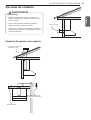
Opciones de conducto
ADVERTENCIA
Riesgo de fuego
%NUNCA extraiga aire o termine el conducto en
espacios entre paredes, espacios angostos, techos,
áticos o garajes.
%Toda la extracción debe realizarse al exterior.
%Utilice únicamente conductos de metal.
%Fije todas las conexiones con tornillos para metal y
cubra todas las juntas con cinta plateada o cinta de
conducto certificada.
Ejemplos de opciones de conducto
Inclinación del tejado con
vierteaguas y tope
6R¿WRRHQWUHSLVR
Tapa lateral de pared con
amortiguador de gravedad
Conducto trasero

12 PLANIFICACIÓN DE LA INSTALACIÓN
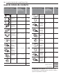
Hoja de cálculo de conducto
Piezas de conducto Longitud
equivalente x
número usado
=
Total
Rectangular,
recto
3-1/4" x 10"
1 Ft. x ( ) = Ft.
6" redondo,
recto 1 Ft. x ( ) = Ft.
7"-10"
redondo, recto 1 Ft. x ( ) = Ft.
3-1/4" x 10"
rectangular,
FRGRGHÛ
15 Ft. x ( ) = Ft.
3-1/4" x 10"
Rectangular,
FRGRGHÛ
9 Ft. x ( ) = Ft.
3-1/4" x 10"
Rectangular,
codo plano de
Û
24 Ft. x ( ) = Ft.
3-1/4" x 10"
Rect. Tope
de pared con
compuerta
30 Ft. x ( ) = Ft.
3-1/4" x 10"
Rect.
transición
redonda de 6"
5 Ft. x ( ) = Ft.
3-1/4" x 10"
Rect.
transición
redonda de 6"
FRGRGHÛ
20 Ft. x ( ) = Ft.
6" redondo,
FRGRGHÛ 15 Ft. x ( ) = Ft.
6" redondo,
FRGRGHÛ 9 Ft. x ( ) = Ft.
Subtotal columna 1 = Ft.
Piezas de conducto Longitud
equivalente x
número usado
=
Total
6" tope de
pared redondo
con compuerta
30 Ft. x ( ) = Ft.
6" redondo,
tope de tejado 30 Ft. x ( ) = Ft.
6" redondo
para transición
rectangular
3-1/4" x 10"
1 Ft. x ( ) = Ft.
6" redondo
para transición
rectangular,
3-1/4" x 10"
codo de 90º
16 Ft. x ( ) = Ft.
7" - 10"
redondo, codo
de 90º
15 Ft. x ( ) = Ft.
7" - 10"
redondo,
codo de 45º
9 Ft. x ( ) = Ft.
7" - 10"
Tope de pared
redondo con
apertura
30 Ft. x ( ) = Ft.
7" - 10"
redondo, tope
de tejado
30 Ft. x ( ) = Ft.
7" redondo
a transición
rectangular
3-1/4" x 10"
8 Ft. x ( ) = Ft.
7" round to
3-1/4" x 10"
rect. transition
ÛHOERZ
23 Ft. x ( ) = Ft.
Subtotal columna 2 = Ft.
Subtotal columna 1 = Ft.
Total conducto = Ft.
Longitud máx. del conducto: Para un movimiento de
aire satisfactorio, la longitud total del conducto no debería
superar el equivalente a 100 pies.

13
PLANIFICACIÓN DE LA INSTALACIÓN
ESPAÑOL
Consejos para el diseño del conducto
Siempre que sea posible, reduzca el número de
transiciones y curvas al menor número de ángulos agudos
que sea posible. Dos instancias de ángulos de 45° son
mejores que una de 90°.
Las curvas deben encontrarse tan lejos del escape de
la campana como sea posible y debe permitirse todo el
espacio que sea posible entre las curvas.
Para un mejor rendimiento, utilice conductos redondos en
lugar de rectangulares, especialmente cuando se necesiten
codos.
Si se utilizan varios codos, trate de mantener un mínimo de
24" de conducto recto entre ellos.
Evite el uso de codos adyacentes en “S” o pegados.
En las regiones donde el clima sea extremadamente
frío, utilice barreras térmicas, como una sección corta de
conducto no metálico, para evitar la pérdida de calor del
interior. Ubique la barrera lo más cerca posible del punto de
paso al exterior.
No utilice conductos de metal flexible.
No use conductos que sean más pequeños en el área
de la sección transversal que los tipos recomendados
anteriormente.
Suministro de energía
ADVERTENCIA
%La información de este manual se debe seguir
exactamente. Si no lo hace, podría provocar un
incendio o una descarga eléctrica, causando daños
a la propiedad, lesiones personales o la muerte.
%Todo el trabajo eléctrico debe ser realizado por
un electricista cualificado o una persona con
conocimiento y experiencia técnica similar.
%Para su seguridad persona, extraiga el fusible o
abra el interruptor de circuitos antes de comenzar
la instalación. No utilice un extensor de cables o
enchufe adaptador con este aparato.
%Siga los códigos eléctricos nacionales o los
códigos y ordenanzas locales.
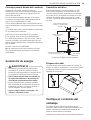
Suministro eléctrico
Este aparato requiere un suministro eléctrico de 120V
60Hz, y debe conectarse a un circuito ramal con una
conexión a tierra adecuada, protegido por un interruptor
de circuitos de 15 o 20 amperios o un fusible de acción
retardada. El cableado debe ser un cable de 2 cables
con tierra. Consulte la etiqueta Diagrama eléctrico en el
producto.
VERDE
BLANCO
BLANCO
NEGRO
NEGRO
VERDE
Remates para cables,
3 ubicaciones
Caja de empalmes
Al panel de interruptores de
circuitos o la caja de fusibles
del hogar.
Alivio de tensión NEMA con
aprobación de UL/CSA A la campana
extractora
Conexión de 3 cables a caja de empalmes
Bloqueo de cable
Las ordenanzas locales pueden requerir un conector de
bloqueo de cable (no suministrado). Consulte los requisitos
y ordenanzas locales y compre e instale el conector
apropiado si es necesario.
Bloqueo de cable
Verifique el contenido del
embalaje
Desembale la caja y verifique que todas las piezas y
accesorios están incluidos. Si falta algún elemento o está
dañado, contacte con el distribuidor de inmediato. No
instale un aparato dañado o incompleto.
Asegúrese de que tiene todo lo necesario para la instalación.

14 INSTRUCCIONES DE INSTALACIÓN
INSTRUCCIONES DE
INSTALACIÓN
ADVERTENCIA
%No instale la campana extractora, a menos que el
suministro de energía eléctrica del domicilio cumpla
con las especificaciones de la campana.
%Respete todos los códigos y las ordenanzas vigentes
durante la instalación. Póngase en contacto con el
departamento de construcción de su localidad para
obtener más información.
%La instalación de este artefacto empotrable debe ser
realizada por un técnico calificado. Hace falta más de
una persona para levantar la campana en su lugar.
El propietario es responsable de que la campana se
instale correctamente.
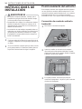
1Comience quitando los filtros de la parte inferior de la
campana. Colóquelos en un lugar seguro para que no
se dañen.
2Si se va a instalar la campana para que evacue el aire
por la parte posterior, los extractores deben girarse a
la posición correcta antes de colgar la campana.
Posicionamiento del extractor
Esta campana extractor está equipada de forma estándar
con una opción de conducto vertical redondo de 8". Para
convertir el conducto vertical redondo de 8" a un conducto
horizontal redondo de 8" o un conducto rectangular
horizontal de 3-1/4" x 10" siga las instrucciones siguientes.
Conversión de conducto vertical a
horizontal
1Desconecte el enchufe del soplador.
2Quite los 4 tornillos en el interior de la campana
que unen la placa del soplador individual a la parte
superior del cuerpo de la campana. Retire el soplador
individual y la placa del soplador.
3En la parte posterior, remueva la placa B para
conductos rectangulares, o la placa C para conductos
circulares de 8 pulgadas.
C
B

15
INSTRUCCIONES DE INSTALACIÓN
ESPAÑOL
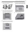
4Quite los 4 tornillos que sujetan el soplador a la placa
del soplador. Gire el soplador 180 grados y vuelva a
ajustarlo a la placa del soplador.
5Coloque el soplador individual y la placa del soplador
tal como se muestra, colocando la parte posterior
de la placa del soplador en las lengüetas de la
parte posterior de la campana. Asegure la placa del
soplador usando los 4 tornillos del paso 2.
6Fije un collar de conducto circular de 8" o un collar
rectangular de 3 1/4" x 10" a la parte posterior del
cuerpo de la campana utilizando cuatro tornillos M3.5
x 8.
7Desde el interior del cuerpo de la campana, alinee la
placa superior con la parte superior del cuerpo de la
campana. Fije la cubierta superior desde el exterior
de la campana, utilizando cuatro tornillos de 3/16 "x
3/8".
8Conecte el enchufe del soplador.

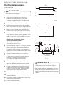
16 INSTRUCCIONES DE INSTALACIÓN
Montaje de la campana
extractora
PRECAUCIÓN
%Se requieren al menos dos instaladores debido al
peso y tamaño de la campana.
1Seleccione la orientación del conducto de su
preferencia (vertical u horizontal) y prepare la
campana. Consulte la página 14 en referencia al
conducto horizontal de un soplador individual.
2Compruebe el nivel y marque la línea central.
3Elija la altura deseada por encima de la superficie
de la cocina (mínimo 26"). Nivele y marque ela parte
inferior de la campana (línea A en la figura 1).
4Nivele y marque la parte superior del tablero de
madera (línea B en la figura 1), 16 7/8" de la línea A.
5Dibuje una línea central en el tablero de madera tal
como se muestra. Alinee el centro del tablero con la
línea central en la pared y alinee la parte superior del
tablero con la línea B. Sujete el tablero a los clavos
de la pared usando cuatro tornillos para madera M6.
Dimensiones del tablero de madera:
(Ancho x Profundidad x Altura)
SKSPH3602S - 33" x 1/2" x 4"
SKSPH4802S - 45" x 1/2" x 4"
6Prepare el tubo de conducto y los cortes de conducto
en el armario superior si fuera necesario, o en la
pared si conectará la campana horizontalmente.
Consulte las especificaciones de la campana en la
página 8 para conocer las dimensiones de los cortes
de conducto.
7Prepare el cableado eléctrico y las conexiones
eléctricas en el armario superior si fuera necesario,
o en la pared si se requiere un montaje eléctrico
horizontal. Consulte las especificaciones de
la campana en la página 8 para conocer las
dimensiones de las conexiones eléctricas.
8Instale la campana sobre el tablero de madera y
asegúrela utilizando cuatro tornillos para madera
M6.
9Inserte dos tornillos para madera M6 en la pared
a través de los agujeros para tornillos en la parte
inferior del cuerpo. Vea la Fig. 2 para conocer las
dimensiones entre los agujeros para tornillos.
10 Instale la conexión eléctrica.
11 Instale el conducto y séllelo con cinta adhesiva de
aluminio certificada.
12 Encienda la campana y verifique que no haya fugas
alrededor de la cinta adhesiva.
13 Instale los filtros deflectores.
C/L
C/L
A
B
16
7
/
8
"
min 26"
4"
tablero de madera
FIG. 1
3
5
/
16
"
21
1
/
4
"
5
5
/
16
"
16
7
/
8
"
27
3
/
8
" (36" & 42"),
35
1
/
4
" (48" & 54")
1
11
/
16
"
16
1
/
8
"
13
5
/
8
"
FIG. 2
ADVERTENCIA
%El cableado eléctrico debe ser realizado por personal
cualificado de acuerdo con todos los códigos y
normas aplicables.
%Esta campana debe estar debidamente conectada
a tierra. Desconecte la alimentación eléctrica de la
fuente de alimentación principal antes de realizar el
cableado.

17
DIAGRAMA DE CABLEADO
ESPAÑOL
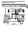
DIAGRAMA DE CABLEADO
Modelos Voltios Hz Amps Máx.
SKSPH4802S
SKSPH3602S 120 60 Motor individual 4
Motor doble 7
MOTOR
BLUE
BROWN
GRAY
AC N
TRANSFORMER
WHITE
GREEN
BLACK
WHITE
BODY
BLACK
REMARKS:CONDENSER 11+11uF 250VAC 2 FIT AC120V 60Hz
AC L
GRAY
BLUE
BROWN
GREEN
LO
MID
HI
YELLOW
YELLOW
YELLOW
YELLOW
COM
FUSE
YELLOW
RED
WHITE
MOTOR
GREEN
YELLOW
RED
WHITE
RED
RED
CONTROL PC
GRAY
BLUE
BROWN
Wi-Fi PCB
BLACK
WHITE
GREEN
Wi-Fi PCB

Customer Information Center
For inquires or comments, call:
1-855-790-6655 USA
-
 1
1
-
 2
2
-
 3
3
-
 4
4
-
 5
5
-
 6
6
-
 7
7
-
 8
8
-
 9
9
-
 10
10
-
 11
11
-
 12
12
-
 13
13
-
 14
14
-
 15
15
-
 16
16
-
 17
17
-
 18
18
-
 19
19
-
 20
20
-
 21
21
-
 22
22
-
 23
23
-
 24
24
-
 25
25
-
 26
26
-
 27
27
-
 28
28
-
 29
29
-
 30
30
-
 31
31
-
 32
32
-
 33
33
-
 34
34
-
 35
35
-
 36
36


Signature Kitchen Suite SKSPH4802S Guía de instalación
- Categoría
- Campanas de cocina
- Tipo
- Guía de instalación
- Este manual también es adecuado para