
04/15 2015 JM HEAT STAR, Inc., 4560 W. 160TH ST., CLEVELAND, OHIO 44135 • 866-447-2194
WARNING:
· Do not store or use gasoline or other flammable vapors and liquids in the vicinity of this or any
other appliance.
· An LP cylinder not connected for use shall not be stored in the vicinity of this or any other
appliance.
· WHAT TO DO IF YOU SMELL GAS
• Do not try to light appliance.
• Extinguish any open flame.
• Shut off gas to appliance.
· Service must be performed by a qualified service agency.
This is an un-vented gas-fired portable heater. It uses air (oxygen) from the area in which it is used.
Adequate combustion and ventilation must be provided. Refer to pages 4 & 5.
FORCED AIR DUAL-FUEL NOMAD
HEATER
If the information in this manual is not followed exactly, a fire or explosion
may result, causing property damage, personal injury or loss of life.
HS115TC
HS190TC
HS250TC
OPERATING INSTRUCTIONS
AND OWNER’S MANUAL
READ INSTRUCTIONS CAREFULLY: Read and follow all instructions. Place instructions in a safe place
for future reference. Do not allow anyone who has not read these instructions to assemble, light, adjust
or operate the heater.
Model #
LANGUAGES INCLUDED
•ENGLISH
•FRENCH
•SPANISH

2
Forced-Air Dual-Fuel NOMAD Construction Heater Operating Instructions and OwnerÊs Manual
CONTENTS
WARNINGS ..........................................................................2
SPECIFICATIONS ...................................................................3
OPERATING PRECAUTIONS ..................................................4
SAFETY PRECAUTIONS .........................................................4
ODOR FADE WARNING ........................................................5
ASSEMBLY AND PREPARATION FOR OPERATION ..................6
HOSE AND REGULATOR INFORMATION ...............................6
FUEL AND RATE SELECTION .................................................7
OPERATION .........................................................................7
USING THE ACCESSORIES ...................................................8
SHUT DOWN AND STORAGE ...............................................9
MAINTENANCE ....................................................................9
PROPANE TANK SIZE SELECTION ........................................10
TROUBLESHOOTING .......................................................... 11
WIRING DIAGRAM ............................................................. 12
PARTS LISTS AND EXPLODED VIEWS .................................. 13
WARRANTY INFORMATION ...............................................20
WARNING:
FIRE, BURN, INHALATION, AND EXPLOSION HAZARD.
KEEP SOLID COMBUSTIBLES, SUCH AS BUILDING
MATERIALS, PAPER OR CARDBOARD, A SAFE DISTANCE
AWAY FROM THE HEATER AS RECOMMENDED BY THE
INSTRUCTIONS. NEVER USE THE HEATER IN SPACES
WHICH DO OR MAY CONTAIN VOLATILE OR AIRBORNE
COMBUSTIBLES, OR PRODUCTS SUCH AS GASOLINE,
SOLVENTS, PAINT THINNER, DUST PARTICLES OR UN-
KNOWN CHEMICALS.
WARNING:
NOT FOR HOME OR RECREATIONAL VEHICLE USE
WARNING:
YOUR SAFETY IS IMPORTANT TO YOU AND TO OTHERS,
SO PLEASE READ THESE INSTRUCTIONS BEFORE YOU
OPERATE THIS HEATER.
GENERAL HAZARD WARNING:
FAILURE TO COMPLY WITH THE PRECAUTIONS AND
INSTRUCTIONS PROVIDED WITH THIS HEATER, CAN
RESULT IN DEATH, SERIOUS BODILY INJURY AND
PROPERTY LOSS OR DAMAGE FROM HAZARDS OF FIRE,
EXPLOSION, BURN, ASPHYXIATION, CARBON MONOX-
IDE POISONING, AND/OR ELECTRICAL SHOCK.
ONLY PERSONS WHO CAN UNDERSTAND AND FOLLOW
THE INSTRUCTIONS SHOULD USE OR SERVICE THIS
HEATER.
IF YOU NEED ASSISTANCE OR HEATER INFORMATION
SUCH AS AN INSTRUCTIONS MANUAL, LABELS, ETC.
CONTACT THE MANUFACTURER.
THE STATE OF CALIFORNIA REQUIRES THE FOLLOWING WARNINGS:
WARNING: Combustion by-products produced when using this product contain carbon monoxide, a chemical
known to the State of California to cause cancer and birth defects (or other reproductive harm).
WARNING: This product contains chemicals known to the State of California to cause cancer and birth defects
or other reproductive harm.
This NOMAD Forced Air Duel-fuel construction
heater was Assembled in the U.S.A. by:
Enerco Group Inc. 4560 West 160th Street
Cleveland, Ohio 44135
For Questions and Inquiries Contact us at:
CALL: 866-447-2194
FAX: 800-321-0552
VISIT: HEATSTARBYENERCO.COM.
Office hours are:
Monday - Friday 8:00am - 5:00pm

Operating Instructions and OwnerÊs Manual
3
Forced-Air Dual-Fuel NOMAD Construction Heater
MODEL# (Stock#) HS115TC (F109100) HS190TC (F109110) HS250TC (F109120)
PROPANE BTU/kW INPUT
HIGH LP (kW) 110,833 BTU/HR (32kW) 190,200 BTU/HR (56kW) 248,625 BTU/HR (73kW)
LOW LP (kW) 80,612 BTU/HR (24kW) 127,100 BTU/HR (37kW) 181,119 BTU/HR (53kW)
HIGH NG (kW) 107,586 BTU/HR (32kW) 183,600 BTU/HR (54kW) 248,625 BTU/HR (73kW)
LOW NG(kW) 77,124 BTU/HR (23kW) 128,700 BTU/HR (38kW) 172,252 BTU/HR (50kW)
OPERATINGS GAS PRESSURES (W.C./kPa)
MAX IN-LP TANK PRESSURE TANK PRESSURE TANK PRESSURE
MAX IN-NG (Kpa) 14" W.C. (3.49 Kpa) 14" W.C. (3.49 Kpa) 14" W.C. (3.49 Kpa)
MIN IN-LP (Kpa) 15 PSI (103.4 Kpa) 15 PSI (103.4 Kpa) 15 PSI (103.4Kpa)
MIN IN-NG (Kpa) 7" W.C. (1.74 Kpa) 7" W.C. (1.74 Kpa) 7" W.C. (1.74 Kpa)
MANIFOLD PRESSURE 4" W.C. (.99 Kpa) 4" W.C. (.99 Kpa) 4" W.C. (.99 Kpa)
FUEL CONSUMPTION PER HOUR
LP-HIGH LBS (Kg) 5.326 LBS/HR (2.41 Kg) 8.8 LBS/HR (3.99Kg) 12.042 LBS/HR (5.46 Kg)
LP-LOW LBS (Kg) 3.937 LBS/HR (1.78 Kg) 6.253 LBS/HR (2.83 Kg) 8.568 LB/HR (3.88 Kg)
NG-HIGH MCF .110 MCF .185 MCF .240 MCF
NG-LOW MCF .08 MCF .130 MCF .175 MCF
ELECTRICAL SPECIFICATIONS
ELEC. SUPPLY
(VOLTS/Hz/PHASE) 115V-60HZ- 1Ø 115V-60HZ-1Ø 115V-60HZ-1Ø
CONTINUOUS AMPS 3.5 AMPS 5.5 AMPS 8 AMPS
MOTOR H.P. 1/3HP 1/2HP 3/4HP
MOTOR WATTS 220 W 500 W 800 W
MOTOR R.P.M. 1100 1100 1035
HEATER DIMENSIONS/WEIGHTS
HEATER WEIGHT 91 LBS (40.3KG) 159 LBS (72 KG) 165 LBS (75 KG)
HEATER DIMENSIONS
(LxWxH)
30" x 23.75" x 15" 35.75" x 34.75" x 20.25" 35.75" x 34.75" x 20.25"
CARTON WEIGHT
(LBS/K.G.)
102 LBS (46.3KG) 176 LBS (79.8 KG) 182 LBS (83 KG)
CARTON DIMENSIONS
(LxWxH)
34.5" x 25.75" x 20" 39" x 36.75" x 24.25" 39" x 36.75" x 24.25"
SPECIFICATIONS
TOP SIDES BACK OUTLET
HS115TC 1' 1' 1' 6'
HS190TC 1' 1' 1' 6'
HS250TC 1' 1' 1' 6'
CLEARANCE TO COMBUSTIBLES

4
Forced-Air Dual-Fuel NOMAD Construction Heater Operating Instructions and OwnerÊs Manual
OPERATING PRECAUTIONS
This is a propane or natural gas, direct-fired, forced air
heater. It's intended use is primarily temporary heating of
buildings under construction, alteration or repair.
Propane is heavier than air. If the fuel leaks from a
connection or fitting, it sinks to the floor, collecting there
with the surrounding air, forming a potentially explosive
mixture. Obviously, fuel leaks should be avoided, so set up
the fuel supply with utmost care. Read the Odor Fade and
Propane warnings included in this manual for additional
information about detecting gas leaks. Leak check new
connections or re-connections with a soap and water
solution and follow all connection instructions herein. Also,
ask your propane dealer or natural gas supply company for
advice on the heater application and supply installation and
ask him to check it if there are any questions.
This heater was designed and certified for use as a
construction heater in accordance with ANSI Standard
Z83.7/CSA 2.14. Check with your local fire safety authority
if you have any questions about your applications. Other
standards govern the use of fuel gases and heat producing
products in specific applications. Your local authority can
advise you about these.
Direct-Fired means that all of the combustion products enter
the heated space. Even though this heater operates very
close to 100 percent combustion efficiency, it still produces
small amounts of carbon monoxide. Carbon monoxide
(called CO) is toxic. We can tolerate small amounts but not a
lot. CO can build up in a heated space and failure to provide
adequate ventilation could result in death. The symptoms of
inadequate ventilation are:
• headache
• dizziness
• burning eyes and nose
• nausea
• dry mouth or sore throat
So, be sure to follow advice about ventilation in these
operating instructions.
Forced Air means that a blower or fan pushes the air
through the heater. Proper combustion depends upon this
air flow; therefore, the heater must not be revised, modified
or operated with parts removed or missing. Likewise, safety
systems must not be circumvented or modified in order to
operate the heater.
When the heater is to be operated in the presence of other
people the user is responsible for properly acquainting those
present with the safety precautions and instructions, and of
the hazards involved.
SAFETY PRECAUTIONS
1. Check the heater thoroughly for damage. DO NOT
operate a damaged heater.
2. DO NOT modify the heater or operate a heater which has
been modified from its original condition.
3. Use only fuel types for which the heater has been
certified.
4. If using propane use only VAPOR WITHDRAWAL type
propane supply. If there is any question about vapor
withdrawal, ask your propane dealer.
5. Mount the propane cylinders vertically (shutoff valve
up). Secure them from falling or being knocked over and
protect them from damage.
6. Locate propane containers at least (USA) 7 ft. (2.13m),
(Canada) 10 ft. (3m) from the heater and do not direct
exhaust toward containers.
7. IMPORTANT Use only the hose and regulator assembly
provided with the heater. Inspect hose assembly before
each use of the heater. If there is excessive abrasion or
wear, or hose is cut, replace with hose assembly listed on
parts list in this manual before using heater.
8. For indoor or outdoor use where adequate ventilation has
been provided. Minimum openings of 1/2 sq. ft. (.046
m²) near the floor and 1/2 sq. ft. (.046 m²) near the
ceiling (also see "Operating Precautions").
9. If at any time gas odor is detected, IMMEDIATELY
DISCONTINUE operation until the source of gas has been
located and corrected. Read enclosed Odor fade and
Propane information for additional information about
detecting propane or natural gas leaks.
10. While this heater is designed to withstand a reasonable
about of harsh weather. It is best to install the heater such
that it is not directly exposed to water spray, rain and/or
dripping water.
11. Maintain minimum clearance from normal combustible
material like paper, canvas, plastic tarpaulins or similar
coverings and secure them to prevent flapping or
movement due to wind action.
12. Due to the high surface and exhaust temperatures, adults
and children must observe clearances to avoid burns or
clothing ignition.
13. Operate only on a stable, level surface.
14. For use with only approved duct lengths and materials.
15. Use only the electrical power specified. The electrical
connection and grounding must comply with National
Electrical Code - ANSI/NFPA 70 (USA) and CSA C22.1
Canadian Electrical Code, Part 1 (Canada).
16. Use only a properly grounded 3-prong receptacle or
extension cord (6 ft (1.83m) in length minimum).
17. Do not move, handle or service while hot or burning.
18. Use only in accordance with local codes or, in the absence
of local codes, with the Standard for the Storage and
Handling of Liquefied Petroleum Gases ANSI/NFPA 58 and
CSA B149.1, Natural Gas and Propane Installation Code.

Operating Instructions and OwnerÊs Manual
5
Forced-Air Dual-Fuel NOMAD Construction Heater
FUEL GAS ODOR
LP gas and natural gas have man-made odorants
added specifically for detection of fuel gas leaks.
If a gas leak occurs you should be able to smell
the fuel gas. Since these fuels are heavier than air
you should smell for the gas odor low to the floor.
ANY GAS ODOR IS YOUR SIGNAL TO GO INTO
IMMEDIATE ACTION!
• Do not take any action that could ignite the fuel gas.
Do not operate any electrical switches. Do not pull
any power supply or extension cords. Do not light
matches or any other source of flame. Do not use your
telephone.
• Get everyone out of the building and away from the
area immediately.
• Close all propane (LP) gas tank or cylinder fuel supply
valves, or the main fuel supply valve located at the
meter if you use natural gas.
• Propane (LP) gas is heavier than air and may settle in
low areas. When you have reason to suspect a propane
leak, keep out of all low areas.
• Use your neighborÊs phone and call your fuel gas
supplier and your fire department. Do not re-enter the
building or area.
• Stay out of the building and away from the area until
declared safe by the firefighters and your fuel gas
supplier.
• FINALLY, let the fuel gas service person and the
firefighters check for escaped gas. Have them air out
the building and area before you return. Properly
trained service people must repair any leaks, check for
further leakages, and then relight the appliance for
you.
ODOR FADING - NO ODOR DETECTED
• Some people cannot smell well. Some people cannot
smell the odor of the man-made chemical added to
propane (LP) or natural gas. You must determine if you
can smell the odorant in these fuel gases.
• Learn to recognize the odor of propane (LP) gas
and natural gas. Local propane (LP) gas dealers will
be more than happy to give you a scratch and sniff
pamphlet. Use it to become familiar with the fuel gas
odor.
• Smoking can decrease your ability to smell. Being
around an odor for a period of time can affect your
sensitivity to that particular odor. Odors present in
animal confinement buildings can mask fuel gas odor.
• The odorant in propane (LP) gas and natural gas
is colorless and the intensity of its odor can fade
under some circumstances.
• If there is an underground leak, the movement of gas
through the soil can filter the odorant.
• Propane (LP) gas odor may differ in intensity at
different levels. Since Propane (LP) gas is heavier than
air, there may be more odor at lower levels.
• Always be sensitive to the slightest gas odor. If
you continue to detect any gas odor, no matter how
small, treat it as a serious leak. Immediately go into
action as discussed previously.
ATTENTION- CRITICAL POINTS TO REMEMBER
• Propane (LP) gas has a distinctive odor. Learn to
recognize these odors. (Reference Fuel Gas Odor and
Odor Fading sections above.
• Even If you are not properly trained in the service and
repair of the heater, ALWAYS be consciously aware of
the odors of propane (LP) gas and natural gas.
• If you have not been properly trained in repair and
service of propane (LP) gas then do not attempt to
light heater, perform service or repairs, or make any
adjustments to the heater on the propane (LP) gas fuel
system.
• A periodic sniff test around the heater or at the
heaterÊs joints; i.e. hose, connections, etc., is a good
safety practice under any conditions. If you smell even
a small amount of gas, CONTACT YOUR FUEL GAS
SUPPLIER IMMEDIATELY. DO NOT WAIT!
UNPACKING (Tools needed: Box cutter)
Remove heater and all components from cardboard
container. Thoroughly inspect all packing material for
pieces that are not garbage. Next check the unit for
possible shipping damage. If any is found immediately
notify the factory.
ODOR FADE WARNING
WARNING- ASPHYXIATION HAZARD
Do not use this heater for heating human living quarters.
• Do not use in unventilated areas.
• The flow of combustion and ventilation air must not be obstructed.
• Proper ventilation air must be provided to support the combustion air requirements of the heater being used.
• Refer to the specification section of the heaterÊs manual, heater data-plate, or contact the Factory to determine
combustion air ventilation requirements of the heater.
• Lack of proper ventilation air will lead to improper combustion.
• Improper combustion can lead to carbon monoxide poisoning leading to serious injury or death. Symptom of carbon
monoxide poisoning can include headaches dizziness and difficulty in breathing.

6
Forced-Air Dual-Fuel NOMAD Construction Heater Operating Instructions and OwnerÊs Manual
Assembly
INSTALLING THE WHEELS & FOOT (Tools needed: Pliers)
Most units will be completely assembled. However if for
any reason you do need to assemble these components
follow the these instructions. Using the cardboard that
your heater was shipped in turn your heater on to one
of it sides or its top so that the bottom of the heater is
accessible. First, take the axel and insert it into one of the
wheels supplied. Then on the outside of the wheel place
the large washer over the axle. You can then insert one
of the cotter pins into the hole in the end of the axle and
bend over one or both of the tails of the pin so that it
cannot be removed. Then on the inside of that wheel run
one of the spacers over the other end of the axel so that
it is pressed against the back of the wheel. Then slide the
axle into the holes along the bottom edge of the heater.
Then install the other spacer followed by the other wheel
and washer. You can then insert and bend the other
cotter pin. Finally you can press the rubber hub caps over
the end of the axle. It is designed to press over the washer
to hold the cap in place once you are sure you have the
wheels and axle installed on your heater in the order
shown in figure 1.
INSTALLING THE HANDLE
Most units will be completely assembled. However if for
any reason you do need to assemble these components
follow the these instructions. First locate the metal "U"
shaped handle that was packed with your heater. (Does
not apply to model # HS115TC, If this is your model
move to hose and regulator setup). Next locate the two
handle bolts included in your hardware package. Then,
while looking at the outlet side of the heater open the
access panel opposite the control panel side by removing
the screws that hold it in place around its perimeter. Just
above the top edge of the door opening you should see
two holes close to the top edge of the heater. Align the threaded
holes in the handle up to the holes in the cover of the heater.
Then thread the two supplied bolts through the case into the
handle from inside of the case. Using a socket wrench tighten
down the bolts. Be sure not to over tighten.
Hose and Regulator setup
SETUP FOR PROPANE
First locate the hose and regulator assembly included with
your heater. Inspect the hose for cracks, breaks and any
signs of damage. If any damage is found, contact the factory
for a replacement. The regulator end is equipped with a
standard POL connection designed to fit most vertical vapor
draw propane tanks. Note: This is a reverse "left hand"
thread. Next attach the P.O.L. to an appropriately sized tank
for your application. This is a flared fitting and this type of
connection does not require any additional sealant or thread
tape. Check all connections with a mixture of soap and
water for leaks. Mix water and a small amount of dish soap
in a spray bottle and apply the solution on all connections, looking
for small bubbles to appear. If you see bubbles that is an indication
of a leak. Tighten your connection until the bubble are eliminated.
For proper tank sizing, refer to the sizing chart in the trouble
shooting section of this manual. (page 10)
SETUP FOR NATURAL GAS.
You must first determine if a regulator will be
required. When using NG a regulator will only be
required when the source of the gas has an output
pressure greater than 14" w.c. (3.48 Kpa).
First locate the hose and regulator assembly included with
your heater. Inspect the hose for any cracks breaks or signs
of damage. If any damage is found, contact the factory
for a replacement. The regulator end is equipped with
a standard POL connection designed to fit most vertical
vapor draw propane tanks. If you are using your unit with
Natural Gas and you have determined the regulator will
be needed, first the "P.O.L. fitting will have to be removed
and replaced with a connector/connectors that will allow
for connection to your Natural Gas supply. To remove the
P.O.L. fitting, secure the regulator body in a vice being
careful not to damage it. Then
using a socket wrench remove
he P.O.L. stem and nut from the
regulator. Then replace the POL
with the appropriate pieces to
make your connection. Be sure
to use an appropriate sealant
or thread tape when required.
Check all connections with a
mixture of soap and water for
leaks. Mix water and a small
amount of dish soap in a spray
bottle and apply the solution on
all connections, looking for small
bubbles to appear. If you see bubbles that is an indication
of a leak. Tighten your connection until the bubble are
eliminated.
1
2
3
5
2
3
4
4
# DESCRIPTION QTY
1 WHEELS 2
2 COTTER PINS 2
3 RETAINER WASHERS 2
4 WHEEL SPACERS 2
5 AXLE 1
FIGURE 1
POL
Remove for NG installation

Operating Instructions and OwnerÊs Manual
7
Forced-Air Dual-Fuel NOMAD Construction Heater
power switch). The male plug end of the heater will
go inside the female receptacle on the thermostat plug
end. Next plug in your properly grounded three pronged
extension cord into the other side of the thermostat
plug. You can now switch on your heater and return to
where you have your thermostat located and set the
temperature at which you would like your heater to cycle
on and off at. Once the temperature in the space to be
heated drops below the point at which your thermostat
is set, the green indicator light above the switch will
illuminate and the heat sequence will begin. The unit
will continue to run until the setting of the thermostat
is satisfied. If your heater shuts down for any reason
other than the operator turns it off or the thermostat
is satisfied, refer to the troubleshooting portion of this
manual on page 11.
RATE AND FUEL SELECTION
FUEL SELECTION
When setting up your Nomad heater you will need to
know which fuel you will be using and move the Rate/
Fuel selector switch to the correct settings before use. For
LP you will use the Red settings and rate. For NG you will
use the Blue settings and rates Refer to figure 5.
RATE SELECTION
Your Nomad heater is equipped with multi-rate and dual
fuel technology. During setup of your area to be heated
you have the option to use the heater on either the high
or low setting. In order to bring the heat in your space
up to your desired temperature as quickly as possible set
the heater on its high setting (refer to figure 5). Once
you have your space heated to the desired temperature,
you can then turn your setting to the low position to
maintain your desired temperature resulting in dramatic
cost savings from the lower fuel consumption during the
entire heating project.
OPERATION (NO THERMOSTAT)
Plug in your unit using an appropriately sized properly
grounded three pronged extension cord. Attach the small
length of power cord on the heater to your extension
cord. Once power is supplied to the heater you should
see the green indicator light above the switch light up.
Before you turn on your heater you will want to ensure
that you make your fuel and rate selection. Refer to the
"Rate and fuel selection" section for more information.
You can now flip your power switch to the ON position.
After a few seconds your heater will light and you should
feel hot air begin to emit from the outlet of the heater.
With this setup the heater will run continuously until
the operator flips the switch to the off position. If you
would like your heater to cycle on and off based on
the temperature of the space, you will need to use the
supplied remote thermostat.
OPERATION (WITH THERMOSTAT)
To operate your Nomad heater with a thermostat you will
need to place the thermostat in the environment to be
heated and turn the dial to the lowest temperature. Take
the "Piggy-Back" style plug end that was factory installed
on the thermostat and attach it to the small length of
power cord attached to the heater (located near the
FIGURE 5
INCLUDED THERMOSTAT
Cord to heater Extension cored to power
source
Cord to the
Thermostat
THERMOSTAT HOOKUP
PIGGY BACK PLUG

8
Forced-Air Dual-Fuel NOMAD Construction Heater Operating Instructions and OwnerÊs Manual
heated is needed or required. To use this setup you will
need the end diffuser and the 10' specially designed duct-
ing. To assemble attach one end of the 10' length of duct
to the duct adapter and the other to the end Diffuser.
Then place the end diffuser in the space to be heated.
USING NOMAD HEATER ACCESSORIES
The Nomad line of forced air heaters is designed to be
used as a stand alone gas fired heating appliance. It is
also designed and certified to be used with a collection
of useful accessories. For information on any additional
accessories that may be available for your model refer to
the list of accessories in this booklet or visit www.heat-
starbyenerco.com.
USING NOMAD HEATERS WITH DUCT & DIFFUSERS
When using this heater to heat a party tent or construc-
tion environment from out side of the space you will
need to employ the help of a few different diffuser at-
tachments.
Direct Diffuser & Duct Adapter
A direct diffuser allows the
user to duct the heat being
produced by the Nomad
heater into a space need-
ing heat without having the
heater in that space. To do
this you will need a duct
adapter. The duct adapter at-
taches to special connection
points on the heater that
match up to the connec-
tors on the adapter. Align
the tabs on the adapter to the holes on the heater and
turn clock wise to lock them in place. Next you will need
the flexible duct transition piece. The duct transition is a
short piece of special silicone lined ducting that attaches
the adapter to the End diffuser. With the duct adapter
attached to the heater, place the transition duct piece
over the outside of the adapter ring and tighten down the
strap. The other end of the Duct is then attached to the
diffuser see figure 6. The diffuser is an accessory designed
to help direct the air being discharged from the heater.
The air comes out of the diffuser and spreads out in
multiple directions to better fill the space and heat more
evenly. The channel on top of the diffuser is designed to
hold the tent material from falling in front of the diffuser.
The heater can be used without the diffuser but it is rec-
ommended for more effective and efficient use.
Long Duct & Diffuser
Nomad heaters are also designed to be used with 10'
of flexible duct for when distance from the area to be
DUCT ADAPTER
FIGURE 6
DIFFUSER
12" X 10' SILICONE LINED
FLEXIBLE HEATING DUCT
F109108
12" X 30" TRANSITION DUCT F109107 12" DUCT ADAPTER F109106
16" DUCT ADAPTER F10911616" X 30" TRANSITION DUCT F109117
16" X 10' SILICONE LINED
FLEXIBLE HEATING DUCT
F109118
12" UNIVERSAL DIFFUSER
F109105
16" UNIVERSAL DIFFUSER
F109115
FITS HS115TC
FITS HS115TC
FITS HS190TC & HS250TC
FITS HS115TC
FITS HS190TC & HS250TC
FITS HS190TC & HS250TC

Operating Instructions and OwnerÊs Manual
9
Forced-Air Dual-Fuel NOMAD Construction Heater
SHUTDOWN , STORAGE & MAINTENANCE
When your Nomad heater is no longer needed there are
a few steps you should take to ensure it is ready and in
working condition the next time you need it.
SHUTDOWN
While the heater is running, turn off the gas supply to
the heater and allow the fuel left in the system and in
the hose and regulator to burn off. This should only take
a few seconds. Then at the heater, flip the switch to the
middle or OFF position. You should allow your heater to
completely cool before placing your heater in storage or
before you per-
form any service
or maintenance.
Once the unit
has cooled verify
that the gas has
been shut off.
Then disconnect
the hose and
regulator from
the fuel source.
Next disconnect
the hose from
the inlet fitting
on the heater
and neatly wrap
up your hose
assembly. You
can then place
your hose into storage until it is needed again. On the
HS190TC and HS250TC Nomad units you can use the
optional top mounted storage box to store your heater
hose and regulator along with any other accessories or
tools needed for setup and tear down. Next unplug the
unit and wrap up the thermostat and return it to storage.
Your heater can now be stored.
STORAGE & MAINTENANCE
Before and after extended storage or if the heater was
used in dusty conditions you should thoroughly clean the
heater. With the heater unplugged, use soap, water and
a soft cloth to clean off any loose dust or dirt. While your
Nomad heater is certified to be used outdoor and can
withstand wet weather, water should not be used. This
can cause water to be forced into components where it
should not be. To clean off the inside, you will need a
standard flat head screwdriver to open the access panel.
To clean do not use water, use compressed air to blow
dust and debris from the insides. Once the unit is again
clean shut the door and secure the latch with the screw-
driver used to open it. You can now store your heater
until it is needed again. Be sure to make note of the stor-
age "do's and Don't" listed on this page. At least once a
year or the heater has been used in a dusty environment,
it is recommended that the blower wheel be thoroughly
cleaned. Start by removing the access panel cover on
the blower side of the heater. There are 8 screws on the
HS115 and 14 Screws on the larger HS190 and HS250
(4 and 7 on each side respectively) holding the panel in
place.
Once you have access to the blower motor mounting
plate remove the motor and wheel then use compressed
air to blow off the wheel. If a more aggressive clean-
ing method is required to get the wheel clean you can
remove the wheel from the motor by loosening the set
screw. Water solvents and cleaners can then be utilized to
complete the cleaning. Re install the blower in the reverse
it was removed.
DO NOT....
• Do not store the unit outside.
• Do not lose the components shipped with your
heater.
• Do not store your heater in an area prone to rodents.
They can damage internal wiring and the nesting
material is a fire hazard. Always open and inspect
your heater for signs of insect and rodents before
use especially after long bouts of storage.
SERVICE & REPAIR
A hazardous condition may result if a heater is used that
has been modified or is not functioning properly.
When the heater is working properly:
STORAGE UNIT AVAILABLE FOR THE HS190TC
& HS250TC
1
2
3
4
5
6
7
8
9
8 SCREWS
4 ON EACH SIDE
8
SCREWS
4
ON
E
AC
H
SI
DE
1
1
2
2
3
3
4
4

10
Forced-Air Dual-Fuel NOMAD Construction Heater Operating Instructions and OwnerÊs Manual
PROPANE TANK SIZE SELECTION
Below are a few quick points of reference for when you
need to select propane cylinders for your applications.
There are two major points to consider. What is the
temperature outside? & What are the BTU requirements
of the heater I will be using. While 20lb, 40lb and 100lb
tanks are the most common tank sizes, there are various
other options available. Contact you propane supplier for
details.
LBS OF LP IN THE CYLINDER
MAXIMUM CONTINUOUS BTU OUTPUT PER HOUR
@ VARIOUS TEMPERATURES
0°F (-18°C) 20°F(-7°C) 40°F (4°C)
200 (2 x 100's) 226,000 334,000 428,000
100 113,000 167,000 214,000
80 (2 x 40's) 94,000 137,000 180,000
40 55,000 79,000 105,000
20 36,000 51,000 69,000
PROPANE TANK SELECTION @ 20°F (-7°C)
HIGH SETTING LOW SETTING
HS115TC 110,833 BTU/HR 80,612 BTU/HR
2 X 40LB TANKS 1 X 40LB TANK
HS190TC 190,200 BTU/HR 127,100 BTU/HR
2 X 100LB TANKS 2 X 40LB TANKS
HS250TC 248,625 BTU/HR 181,119 BTU/HR
2 X 100LB TANKS 2 X 100LB TANKS
EXAMPLE TANK SELECTION
20LBS 40LBS 100LBS
18”
29”
48”
12.5”
12.5”
14.5”
• The flame is contained within the heater.
• The flame is essentially blue with perhaps some yel-
low tipping.
• There is no strong disagreeable odor, eye burning or
other physical discomfort.
• There is no smoke or soot internal or external to the
heater.
• There are no unplanned or unexplained shut downs
of the heater.
• The parts lists and wiring diagram show the heater
as it was constructed. Do not use a heater which is
different from that shown. In this regard, use only
the hose, regulator and cylinder connection fitting
(called a POL fitting) supplied with the heater.
For this heater, the regulator must be set as shown in
„SPECIFICATIONS‰. If there is any uncertainty about the
regulator setting, have it checked. A heater which is not
working right must be repaired, but only by a trained,
experienced service person. The heater is equipped with
a 1 year Limited Warranty, for full warranty information
please read page 20. Please include a brief statement
indicating date, place of purchase, the nature of the
problem and proof of purchase for warranty inquiries.
Out-of-warrranty products can be repaired with a charge
for parts and labor. Contact customer service for a list of
certified repair centers near you.

Operating Instructions and OwnerÊs Manual
11
Forced-Air Dual-Fuel NOMAD Construction Heater
Symptom Troubleshooting
Blower does not come on 1. Make sure the switch is either in the on or fan only posi-
tion
2. Verify the extension cord being used is not too long
3. Check power source is 110v
4. Verify the setting on the thermostat is higher than the
temperature in the space to be heated
Blower runs but the burner does not ignite 1. Make sure the switch is in the on position not in the fan
only position
2. Verify that the fuel connected to the unit is turned on and
flowing. It may take a few cycles to get all the air out of
the lines.
3. Make sure the rate and fuel switch are in the desired posi-
tion for the fuel you are using and the setting (high or
low) that you desire.
Unit producing little heat or no heat. 1. Make sure the switch is in the on position not the fan only
position
2. Make sure the rate and fuel switch are in the desired posi-
tion for the fuel you are using and the setting (high or
low) that you desire.
3. Verify that the fuel pressure being supplied to the heater is
adequate. Refer to the specification table in this manual for
required pressures.
4. Make sure the factory supplied hose and regulator are be-
ing used.
Heater will not shut down 1. Verify the switch is in the off position not on or fan only.
2. Check current setting on the thermostat. Is it set to a tem-
perature higher than the space being heated?
3. Heater will only cycle on and off when optional thermostat
is installed.
Unit will not turn on with thermostat installed 1. Verify that the thermostat is installed correctly. Heater will
only cycle on and off when the optional thermostat is
installed.
2. Verify the setting on the thermostat is higher than the
temperature in the space to be heated
3. Check that the power switch is in the "on" position. The
thermostat will only cycle on and off if the power switch is
in the on position
Unit will not turn off with thermostat installed. 1. Verify the setting of the thermostat is lower than the tem-
perature in the space being heated.
2. Verify that the thermostat is installed correctly, the unit
may just be on the on position.
3. Heater may be undersized or for the space being heated.
Red HLS fault light is on 1. Verify that the path of heat is not obstructed.
2. Check for blockage in the duct and at the end diffuser
3. Check the fuel and rate selections are accurate. If the
wrong fuel is selected the unit will over heat.
FOR FURTHER ASSISTANCE
If after you have reviewed the trouble shooting in this
manual and you still require assistance please use any of
the following methods to contact our technical service
department. We will do our absolute best to resolve any
issues or problems that arise. Most problems can be solved in
just a few minutes.
HOURS ARE: Monday- Friday 8:00am until 5:00pm
CALL: 866-447-2194
FAX: 800-321-0552
VISIT: HEATSTARBYENERCO.COM
INQUIRIES IN CANADA ONLY
PLEASE CALL: 877-477-3353
VISIT IPSPOWER.COM

12
Forced-Air Dual-Fuel NOMAD Construction Heater Operating Instructions and OwnerÊs Manual
SW1
L
1
2
2A
1B
1A
2B
ign
n/c
n/c
6
5
4
3
2
1
G
VP
N
L
N
led 2
chassis
ground
G
T1
24vac
sail
switch
SW4
hls
led 4
led 5
Gas
Valve
GV1
M
M1
led 1
SW2
3
2
1
1
5
9
3
1
13
15
11
7
2
14
16
12
8
4
10
2
6
SV1
S
SV2
S
Position
1
2
3
Valve(s) Open
SV1 & SV2
SV2
SV1
Chassis wiring is stranded 18 AWG / 105 C / @ 600 Volts
Igniter wiring is16 AWG / 25KVDC / 10 KVAC
(replace with same ratings)
(all quick connects fully insulated)
SW3
WIRING DIAGRAM-ALL UNITS

Operating Instructions and OwnerÊs Manual
13
Forced-Air Dual-Fuel NOMAD Construction Heater
1
23
511
4
9
10
8
6
11
7
12
13
14
15
16
17
19
18
20
22
21
23
24
25
26
27
29
28
41
42
39
40
30
31
32
34
35
33
38
36
37
# P/N PART DESCRIPTION QTY
1 60801 HEATER FOOT 2
2 60800 HEATER BASE 1
3 60802 SOLENOID SUPPORT 1
4 60818 COMBUSTION CHAMBER -RIGHT 1
5 60820 COMBUSTION CHAMBER -BACK 1
6 60817 COMBUSTION CHAMBER -LEFT 1
7 60819 COMBUSTION CHAMBER -TOP 1
8 60822 COMBUSTION CHAMBER -UPPER FLANGE 1
9 60821 COMBUSTION CHAMBER -LOWER FLANGE 1
10 60823 LOWER BURNER COVER 1
11 60824 COMBUSTION CHAMBER -HEAT SHIELD 2
12 60813 INSIDE BLOWER PANEL 1
13 60815 BLOWER TUBE 1
14 60816 115 BLOWER WHEEL 1
15 60812 OUTSIDE BLOWER PANEL 1
16 60814 MOTOR MOUNTING PLATE 1
17 60843 115 MOTOR - 1/3HP 1
18 60830 SAIL SWITCH 1
19 60938 SAIL SWITCH BRACKET 1
20 60958 HIGH LIMIT SWITCH 1
21 60833 HEATER COVER 1
# P/N PART DESCRIPTION QTY
22 60835 MOTOR DOOR 1
23 60834 CONTROLS DOOR 1
24 60837 DOOR HINGE 1
25 60839 D-RING LATCH/LOCK 1
26 60847 24V RED LED LAMP - FAULT INDICATOR 1
27 60846 24V GREEN LED LAMP - GAS VALVE ON INDICATOR 1
28 60845 120V LED LAMP - GREEN 2
29 60841 MAIN POWER ROCKER SWITCH 1
30 60883 SELECTOR SWITCH BRACKET 1
31 60842 SELECTOR SWITCH 1
32 27808 FLAME CONTROL BOARD 1
33 60810 115 BURNER 1
34 60827 115 IGNITER BURNER PLATE-FRONT 1
35 60139 IGNITER/FLAME SENSE ASSY. 1
36 60831 115 BURNER CLAMP 1
37 60832 115 BURNER CLAMP BASE 1
38 60826 115 IGNITER BURNER PLATE-BACK 1
39 00600 GAS TRAIN ASSY. 1
40 60129 GAS VALVE 1
41 60848 SOLENOID VALVE 2
42 60809 ORIFICE HOLDER 1
EXPLODED VIEW HS115TC

14
Forced-Air Dual-Fuel NOMAD Construction Heater Operating Instructions and OwnerÊs Manual
NOTES:

Operating Instructions and OwnerÊs Manual
15
Forced-Air Dual-Fuel NOMAD Construction Heater
17
29
16
38
36
35
32
34
33
31
11
10
28
27
13
14
12
19
22
24
23
25
26
18
30
21 20
2
67
8
19
3
45
15
37
# P/N PART DESCRIPTION QTY
1 60973 190 COVER 1
2 60904 ELECTRICAL DOOR 1
3 60905 MOTOR DOOR 1
4 60906 FIXED PIECE HANDLE MOUNT 1
5 60908 HANDLE 1
6 60916 DOOR HANDLE 1
7 60913 DOOR HANDLE SPACER 1
8 60917 DOOR LATCH 1
9 60915 HOIST RINGS 4
10 60884 BASE 1
11 60901 BASE FOOT 1
12 60802 SOLENOID SUPPORT 1
13 40940 WHEEL 2
14 60902 AXEL 1
15 28787 WHEEL HARDWARE KIT 1
16 60851 SAIL SWITCH 1
17 60938 SAIL SWITCH BRACKET 1
18 60922 COMBUSTION CHAMBER-TOP 1
19 60891 COMBUSTION CHAMBER-LEFT 1
20 60890 COMBUSTION CHAMBER-RIGHT 1
21 60923 COMBUSTION CHAMBER-RIGHT HEAT SHIELD 1
# P/N PART DESCRIPTION QTY
22 90924 COMBUSTION CHAMBER-LEFT HEAT SHIELD 1
23 60892 COMBUSTION CHAMBER-TOP FLANGE 1
24 60893 COMBUSTION CHAMBER-BOTTOM FLANGE 1
25 60925 BURNER STAND-OFF 1
26 60885 COMBUSTION CHAMBER-LOWER HEAT SHIELD 1
27 60974 BLOWER SHELF 1
28 60975 BLOWER SHELF SUPPORT 1
29 60962 HIGH LIMIT SWITCH 1
30 60894 COMBUSTION CHAMBER SUPPORT 2
31 60977 HOUSING RIGHT SIDE 1
32 60978 BLOWER TUBE 1
33 60981 HOUSING DEFLECTOR ATTACHMENT 1
34 60980 HOUSING INLET ADAPTER 1
35 60976 HOUSING LEFT SIDE 1
36 60979 MOTOR MOUNT 1
37 60998 190 BLOWER WHEEL 1
38 60971 1/2HP MOTOR 190 1
EXPLODED VIEW HS190TC

16
Forced-Air Dual-Fuel NOMAD Construction Heater Operating Instructions and OwnerÊs Manual
NOTES:

Operating Instructions and OwnerÊs Manual
17
Forced-Air Dual-Fuel NOMAD Construction Heater
194
5
3
7
6
2
8
21
20
18
26
23
24
19
2227
28
12 14
13 11
10
31
34
32
35
16
17
29
37
36
33
30
15
38
EXPLODED VIEW HS250TC
# P/N PART DESCRIPTION QTY
1 60903 250 COVER 1
2 60904 ELECTRICAL DOOR 1
3 60905 MOTOR DOOR 1
4 60906 FIXED PIECE HANDLE MOUNT 1
5 60908 HANDLE 1
6 60916 DOOR HANDLE 1
7 60913 DOOR HANDLE SPACER 1
8 60917 DOOR LATCH 1
9 60915 HOIST RINGS 4
10 60900 BASE 1
11 60901 BASE FOOT 1
12 60802 SOLENOID SUPPORT 1
13 40940 WHEEL 2
14 60902 AXEL 1
15 28787 WHEEL HARDWARE KIT 1
16 60851 SAIL SWITCH 1
17 60938 SAIL SWITCH BRACKET 1
18 60922 COMBUSTION CHAMBER-TOP 1
19 60919 COMBUSTION CHAMBER-LEFT 1
20 60918 COMBUSTION CHAMBER-RIGHT 1
21 60923 COMBUSTION CHAMBER-RIGHT HEAT SHIELD 1
# P/N PART DESCRIPTION QTY
22 60924 COMBUSTION CHAMBER-LEFT HEAT SHIELD 1
23 60920 COMBUSTION CHAMBER-TOP FLANGE 1
24 60921 COMBUSTION CHAMBER-BOTTOM FLANGE 1
25 60925 BURNER STAND-OFF 1
26 60885 COMBUSTION CHAMBER-LOWER HEAT SHIELD 1
27 60930 BLOWER SHELF 1
28 60931 BLOWER SHELF SUPPORT 1
29 HIGH LIMIT SWITCH 1
30 60894 COMBUSTION CHAMBER SUPPORT 2
31 60933 HOUSING RIGHT SIDE 1
32 60934 BLOWER TUBE 1
33 60937 HOUSING DEFLECTOR ATTACHMENT 1
34 60936 HOUSING INLET ADAPTER 1
35 60932 HOUSING LEFT SIDE 1
36 60935 MOTOR MOUNT 1
37 60940 250 BLOWER WHEEL 1
38 60960 3/4 HP MOTOR 190 1

18
Forced-Air Dual-Fuel NOMAD Construction Heater Operating Instructions and OwnerÊs Manual
NOTES:

Operating Instructions and OwnerÊs Manual
19
Forced-Air Dual-Fuel NOMAD Construction Heater
# P/N PART DESCRIPTION QTY
1 60129 HONEYWELL GAS VALVE 1
2 60848 SOLENOID VALVE 2
3 70597 3/8" FPT X 3/8" MPT - STREET ELBOW 1
4 60804 3/8" PIPE CLOSE NIPPLE 1
5 60948 ORIFICE HOLDER 1
6 60949 GAS VALVE BRACKET 1
7 60805 3/8" X 3 PIPE NIPPLE 1
8 60955 1/2" FPT X 3/8" MPT - STREET ELBOW 1
9 60954 1/2" PIPE CLOSE NIPPLE 1
10 60956 1/2" X 10" PIPE NIPPLE 1
# P/N PART DESCRIPTION QTY
11 02724 1/2" X 4" PIPE NIPPLE 1
12 60957 1/2" X 1/2" ELBOW 1
13 02744 1/2" MALE FLARE 1
14-A 60881 250 BYPASS ORIFICE 1 1
15-A 60882 250 BYPASS ORIFICE 2 1
16-A 60880 250 MAIN ORIFICE 1
14-B 60878 190 BYPASS ORIFICE 1 1
15-B 60879 190 BYPASS ORIFICE 2 1
16-B 60887 190 BYPASS ORIFICE 2 1
16
57
3
14
2
415 2
8
9
6
1
10
12
11
13
WARNING:
USE ONLY MANUFACTURERÊS REPLACEMENT PARTS. USE OF ANY
OTHER PARTS COULD CAUSE INJURY OR DEATH. REPLACEMENT
PARTS ARE ONLY AVAILABLE DIRECT FROM THE FACTORY AND
MUST BE INSTALLED BY A QUALIFIED SERVICE AGENCY.
FOR SERVICE OR PARTS INQUIRIES
PLEASE CALL: 866-447-2194 OR 216-916-3000
VISIT: WWWHEATSTARBYENERCO.COM
INQUIRIES IN CANADA ONLY
PLEASE CALL: 877-477-3353
VISIT IPSPOWER.COM
COROPORATE ADDRESS
HEATSTAR BY ENERCO
4560 WEST 160TH STREET
CLEVELAND, OHIO 44135
OUR OFFICE HOURS ARE 8:00 AM -5:00 PM EST MONDAY-FRIDAY
WHEN CONTACTING US:
PLEASE HAVE YOUR SERIAL NUMBER AND MODEL NUMBER HANDY.
THESE CAN BOTH BE LOCATED ON THE RATING LABEL LOCATED ON
THE INSIDE OF THE ACCESS PANEL.
RETAIN THIS MANUAL FOR FUTURE REFERENCE.
Gas Train for HS190TC & HS250TC

WARNING:
USE ONLY MANUFACTURERÊS REPLACEMENT PARTS. USE OF ANY OTHER PARTS
COULD CAUSE INJURY OR DEATH. REPLACEMENT PARTS ARE ONLY AVAILABLE DIRECT
FROM THE FACTORY AND MUST BE INSTALLED BY A QUALIFIED SERVICE AGENCY.
PARTS ORDERING INFORMATION:
PURCHASING: Accessories may be purchased at any HEAT STAR local dealer or direct
from the factory
FOR INFORMATION REGARDING SERVICE
Please call Toll-Free 866-447-2194 • HEATSTARBYENERCO.COM
Our office hours are 8:00 AM – 5:00 PM, EST, Monday through Friday.
Please include the model number, date of purchase, and description of problem in all
communication.
LIMITED WARRANTY
The company warrants this product to be free from imperfections in material or
workmanship, under normal and proper use in accordance with instructions of
The Company, for a period of one year from the date of delivery to the buyer. The
Company, at its option, will repair or replace products returned by the buyer to the
factory, transportation prepaid within said one year period and found by the Company
to have imperfections in material or workmanship.
If a part is damaged or missing, call our Technical Support Department at 866-447-2194.
Address any Warranty Claims to the Service Department, HEAT STAR Group, Inc.,
4560 W. 160th St., Cleveland, Ohio 44135. Include your name, address and telephone
number and include details concerning the claim. Also, supply us with the purchase
date and the name and address of the dealer from whom you purchased our product.
The foregoing is the full extent of the responsibility of the Company. There are no
other warranties, express or implied. Specifically there is no warranty of fitness for a
particular purpose and there is no warranty of merchantability. In no event shall the
Company be liable for delay caused by imperfections, for consequential damages, or
for any charges of the expense of any nature incurred without its written consent. The
cost of repair or replacement shall be the exclusive remedy for any breach of warranty.
There is no warranty against infringement of the like and no implied warranty arising
from course of dealing or usage of trade. This warranty will not apply to any product
which has been repaired or altered outside of the factory in any respect which in our
judgment affects its condition or operation.
Some states do not allow the exclusion or limitation of incidental or consequential
damages, so the above limitation or exclusion may not apply to you. This Warranty gives
you specific legal rights, and you may have other rights which vary from state to state.
HEAT STAR Group, Inc. reserves the right to make changes at any time, without notice or
obligation, in colors, specifications, accessories, materials and models.
HEAT STAR, INC., 4560 W. 160TH ST., CLEVELAND, OHIO 44135 • 866-447-2194
ANSI Z83.7b-2009/CSA 2.14b-2009
OPERATING INSTRUCTIONS
AND OWNER’S MANUAL
READ INSTRUCTIONS CAREFULLY: Read and follow all instructions. Place instructions in a safe
place for future reference. Do not allow anyone who has not read these instructions to assemble,
light, adjust or operate the heater.
Model #
PRODUCT REGISTRATION: Thank you for your purchase.
Please log in to HEATSTARBYENERCO.COM to register your product.
HS115TC
HS190TC
HS250TC

04/15 2015 JM HEAT STAR, Inc., 4560 W. 160TH ST., CLEVELAND, OHIO 44135 • 866-447-2194
AVERTISSEMENT :
· NÊentreposez et nÊutilisez pas dÊessence ou dÊautres liquides ou vapeurs inflammables à proximité
de ce type dÊappareil ou de tout autre appareil.
· Un cylindre de gaz propane (liquéfié) non branché pour utilisation ne devrait pas être entreposé
près de cet appareil ou de tout autre appareil.
· QUOI FAIRE SI VOUS SENTEZ DU GAZ
• NÊessayez pas dÊallumer lÊappareil.
• Éteignez toute flamme nue.
• Fermez l'entrée de gaz allant vers l'appareil.
· L'entretien doit être effectué par une entreprise d'entretien accréditée.
Il s'agit d'une fournaise portable alimentée au gaz et non aérée. L'appareil utiliser de l'air (oxygène) de l'endroit où
il est utilisé. Une combustion et une ventilation adéquates doivent être fournies. Référez-vous à aux pages 4 et 5.
FOURNAISE NOMAD À DEUX
COMBUSTIBLES ET À AIR PULSÉ
Si l'information dans ce manuel n'est pas suivie exactement, un incendie
ou une explosion pourrait se produire causant des dommages aux biens,
des blessures personnelles ou un décès.
HS115TC
HS190TC
HS260TC
INSTRUCTIONS D'UTILISATION
ET MANUEL DU PROPRIÉTAIRE
VEUILLEZ LIRE ATTENTIVEMENT LES INSTRUCTIONS : Lire et observer toutes les instructions.
Conserver ces instructions dans un endroit sécuritaire pour vous y référer ultérieurement. Interdisez
à quiconque nÊayant pas lu les présentes instructions d'assembler, d'allumer, de régler ou de faire
fonctionner cette fournaise.
No de modèle
LANGUES INCLUSES
• ANGLAIS
• FRANÇAIS
• ESPAGNOL

22
Forced-Air Dual-Fuel NOMAD Construction Heater Operating Instructions and OwnerÊs Manual
CONTENU
AVERTISSEMENTS ..........................................................................2
SPÉCIFICATIONS ............................................................................ 3
PRÉCAUTIONS LIÉES AU FONCTIONNEMENT ................................. 4
PRÉCAUTIONS DE SÉCURITÉ ..........................................................4
MISE EN GARDE LIÉE AUX SUBSTANCES ODORANTES ................... 5
ASSEMBLAGE ET PRÉPARATION POUR L'UTILISATION .....................6
INFORMATION SUR LE TUYAU ET LE RÉGULATEUR ........................6
SÉLECTION DU COMBUSTIBLE ET DU TAUX ................................... 7
FONCTIONNEMENT .......................................................................7
UTILISATION DES ACCESSOIRES .................................................... 8
ARR¯T ET ENTREPOSAGE .......... ............ ........................................9
ENTRETIEN .....................................................................................9
SÉLECTION DE LA GRANDEUR DU CYLINDRE AU PROPANE ......... 10
DÉPANNAGE .................................................................................11
SCHÉMA DU C˜BLAGE .................................................................12
LISTES DES PI˚CES ET VUES ÉCLATÉES ..........................................13
INFORMATION SUR LA GARANTIE ............................................... 20
AVERTISSEMENT :
DANGER D'INCENDIE, D'INHALATION ET D'EXPLOSION.
GARDEZ LES COMBUSTIBLES SOLIDES TELS QUE LES
MATÉRIAUX DE CONSTRUCTION LE PAPIER ET LE
CARTON ¤ UNE DISTANCE SÉCURITAIRE DE L'APPAREIL
DE CHAUFFAGE TEL QUE RECOMMANDÉ DANS LES
INSTRUCTIONS. N'UTILISEZ JAMAIS LA FOURNAISE
DANS UN ENDROIT QUI CONTIENT OU RISQUE DE
CONTENIR DES COMBUSTIBLES VOLATILES OU EN
SUSPENSION DANS L'AIR, OU DES PRODUITS TELS
QUE DE L'ESSENCE, DES SOLVANTS, DU DILUANT ¤
PEINTURE, DES PARTICULES DE POUSSI˚RE OU DES
PRODUITS CHIMIQUES INCONNUS.
AVERTISSEMENT :
NON CONÇU POUR UNE UTILISATION ¤ L'INTÉRIEUR DE
LA MAISON OU DANS UN VÉHICULE RÉCRÉATIF.
AVERTISSEMENT :
VOTRE SÉCURITÉ EST IMPORTANTE POUR VOUS ET POUR LES
AUTRES, PAR CONSÉQUENT VEUILLEZ LIRE CES DIRECTIVES
AVANT DE FAIRE FONCTIONNER CET APPAREIL DE CHAUFFAGE.
AVERTISSEMENT GÉNÉRAL DE DANGER :
LE NON-RESPECT DES MESURES DE PRÉVENTION ET DES
INSTRUCTIONS FOURNIES AVEC CET APPAREIL DE CHAUFFAGE
RISQUE DE CAUSER LA MORT, DES BLESSURES GRAVES ET
DES DOMMAGES OU DES PERTES MATÉRIELLES RÉSULTANT
D'INCENDIE, D'EXPLOSION, DE BRðLURE, D'ASPHYXIE,
D'INTOXICATION AU MONOXYDE DE CARBONE ET/
OU D'ÉLECTROCUTION. SEULES LES PERSONNES APTES
¤ COMPRENDRE ET ¤ RESPECTER LES INSTRUCTIONS
DEVRAIENT UTILISER OU EFFECTUER LE SERVICE DE CET
APPAREIL DE CHAUFFAGE. SI VOUS AVEZ BESOIN D'AIDE OU
D'INFORMATION CONCERNANT LA FOURNAISE TELS QUE
MANUEL D'INSTRUCTIONS, ÉTIQUETTES, ETC., VEUILLEZ
COMMUNIQUER AVEC LE FABRICANT.
L'ÉTAT DE CALIFORNIE EXIGE QUE L'AVERTISSEMENT SUIVANT SOIT FOURNI :
AVERTISSEMENT :
Les sous-produits de combustion émis lors de l'utilisation de cet appareil contiennent du
monoxyde de carbone, un produit chimique reconnu par l'état de Californie comme pouvant causer le cancer et des malformations
congénitales (ou autres dommages au système reproducteur).
AVERTISSEMENT : Cet appareil contient des produits chimiques reconnus par l'état de Californie comme
pouvant causer le cancer et des malformations congénitales ou autres dommages au système reproducteur.
Cette fournaise NOMAD à deux combustibles et
et air forcé a été assemblée aux États-Unis par :
Enerco Group Inc. 4560 West 160th Street
Cleveland, Ohio 44135 États-Unis
Pour des questions ou des demandes, nous
contacter au :
TÉLÉPHONE : 866-447-2194
TÉLÉCOPIEUR : 800-321-0552
SITE WEB : HEATSTARBYENERCO.COM.
Nos heures de bureau sont les suivantes :
Du lundi au vendredi entre 8 h et 17 h

Operating Instructions and OwnerÊs Manual
23
Forced-Air Dual-Fuel NOMAD Construction Heater
No DE MODÈLE (No de stock) HS115TC (F109100) HS190TC (F109110) HS250TC (F109120)
ENTRÉE BTU/kW DU PROPANE
GPL ÉLEVÉ (kW) 110 833 BTU/H (32 kW) 190 200 BTU/H (56 kW) 248 625 BTU/H (73 kW)
GPL BAS (kW) 80 612 BTU/H (24 kW) 127 100 BTU/H (37 kW) 181 119 BTU/H (53 kW)
GN ÉLEVÉ (kW) 107 586 BTU/H (32 kW) 183 600 BTU/H (54 kW) 248 625 BTU/H (73 kW)
GN BAS (kW) 77 124 BTU/H (23 kW) 128 700 BTU/H (38 kW) 172 252 BTU/H (50 kW)
PRESSIONS DE FONCTIONNEMENT DU GAZ (COLONNE D'EAU/kPa)
GPL D'ENTRÉE MAX. PRESSION DU CYLINDRE PRESSION DU CYLINDRE PRESSION DU CYLINDRE
GN D'ENTRÉE MAX (Kpa) 14 po C.A. (3,49 kPa) 14 po C.A. (3,49 kPa) 14 po C.A. (3,49 kPa)
GPL D'ENTRÉE MIN (Kpa) 15 PSI (103,4 kPa) 15 PSI (103,4 kPa) 15 PSI (103,4 kPa)
GN D'ENTRÉE MIN (Kpa) 7 po C.A. (1,74 kPa) 7" C.A. (1,74 kPa) 7 po C.A. (1,74 kPa)
PRESSION DE LA RAMPE À GAZ
4 po C.A. (0,99 kPa) 4 po C.A. (0,99 kPa) 4 po C.A. (0,99 kPa)
CONSOMMATION DE COMBUSTIBLE À L'HEURE
KG/LB GPL ÉLEVÉ 5,326 LB/H (2,41 Kg) 8,8 LB/H (3,99 Kg) 12,042 LB/H (5,46 Kg)
KG/LB GPL BAS 3,937 LB/H (1,78 Kg) 6,253 LB/H (2,83 Kg) 8,568 LB/H (3,88 Kg)
MCF GN ÉLEVÉ 0,110 MPC 0,185 MPC 0,240 MPC
MCF GN BAS 0,08 MPC 0,130 MPC 0,175 MPC
SPÉCIFICATIONS ÉLECTRIQUES
ÉLEC. ALIMENTATION
(VOLTS/Hz/PHASE) 115 V - 60 HZ - 1 Ø 115 V - 60 HZ - 1 Ø 115 V - 60 HZ - 1 Ø
AMPÈRES EN CONTINU 3,5 AMPS 5,5 AMPS 8 AMPS
H.P. DU MOTEUR 1/3 H.P. 1/2 H.P. 3/4 H.P.
WATTS DU MOTEUR 220 W 500 W 800 W
T/M DU MOTEUR 1100 1100 1035
DIMENSIONS/POIDS DE LA FOURNAISE
POIDS DE LA FOURNAISE 91 LB (40,3 kg) 159 LB (72 kg) 165 LB (75 kg)
DIMENSIONS DE LA FOUR-
NAISE (LxlxH)
30 po x 23,75 po x 15 po 35,75 po x 34,75 po x 20,25
po
35,75 po x 34,75 po x 20,25 po
POIDS DE LA BOÎTE (LB/KG) 102 LB (46,3 kg) 176 LB (79,8 kg) 182 LB (83 kg)
DIMENSIONS DE LA BOÎTE
(LxlxH)
34,5 po x 25,75 po x 20 po 39 po x 36,75 po x 24,25 po 39 po x 36,75 po x 24,25 po
SPÉCIFICATIONS
SUPÉRIEUR CÔTÉS ENDOS SORTIE
HS115TC 1 pi 1 pi 1 pi 6 pi
HS190TC 1 pi 1 pi 1 pi 6 pi
HS250TC 1 pi 1 pi 1 pi 6 pi
DISTANCE DE DÉGAGEMENT DES MATÉRIAUX COMBUSTIBLES

24
Forced-Air Dual-Fuel NOMAD Construction Heater Operating Instructions and OwnerÊs Manual
PRÉCAUTIONS LIÉES AU
FONCTIONNEMENT
C'est une fournaise à air pulsé, à feu direct, au propane ou
au gaz naturel. Son utilisation voulue est premièrement le
chauffage temporaire d'édifices en construction, modification
ou réparation.
Le propane est plus lourd que l'air. Si le combustible s'échappe
d'une connexion ou d'un raccord, il tombe au plancher, se
ramassant là avec l'air environnant, formant un mélange explosif
potentiel. Évidemment, les fuites de combustible doivent être
évitées, donc fixez l'alimentation du combustible avec le plus
grand soin. Lisez les avertissements sur Substances odorantes
et propane inclus dans ce manuel pour plus d'informations sur
la détection de fuites de gaz. Vérifiez toute nouvelle connexion
ou re-connexion pour toute fuite avec une solution de savon et
d'eau et suivez toutes les instructions de connexion du présent
document. Également, demandez des avis à votre revendeur de
propane ou votre fournisseur de gaz naturel sur l'installation de
l'alimentation et de l'application de la fournaise et demandez-lui
de vérifier le tout si vous avez des questions à ce sujet.
Cette fournaise a été conçue et homologuée pour être utilisée
comme appareil de chauffage (fournaise) pour chantier de
construction, conformément à la norme ANSI Z83,7/CSA 2,14.
Veuillez vérifier auprès de votre autorité locale en sécurité et
incendie si vous avez des questions concernant vos applications.
D'autres normes régissent l'utilisation des gaz combustibles et
des produits de combustion lors d'applications spécifiques. Votre
autorité locale saura vous conseiller à cet égard.
¤ feu direct signifie que l'ensemble des produits de combustion
entre l'espace de chauffage. Même si cette fournaise fonctionne
très près d'une efficacité de combustion de 100 pour cent,
elle produit quand même de petites quantités de monoxyde
de carbone. Le monoxyde de carbone (CO) est toxique. Nous
pouvons tolérer de petites quantités mais pas trop. Le CO peut
s'amasser dans un espace chauffé et un échec à fournir une
ventilation adéquate peut causer la mort. Les symptômes d'une
ventilation inadéquate incluent :
• maux de tête
• étourdissement
• yeux et nez qui piquent
• nausée
• bouche sèche ou maux de gorge
Donc, assurez-vous de suivre les conseils de ces instructions de
fonctionnement concernant la ventilation .
¤ air pulsé signifie qu'une souffleuse ou un ventilateur pousse
l'air à travers la fournaise. Une combustion correcte dépend du
flux d'air; ainsi, la fournaise ne doit pas être corrigée, modifiée
ou en fonctionnement avec des pièces enlevées ou manquantes.
De même, les systèmes de sécurité ne doivent pas être
contournés ou modifiés afin de faire fonctionner la fournaise.
Lorsque la fournaise doit fonctionner en présence de
d'autres personnes, l'utilisateur est responsable de renseigner
adéquatement les gens présents avec les précautions et
instructions de sécurité, ainsi que les dangers impliqués.
PRÉCAUTIONS DE SÉCURITÉ
1. Bien vérifier la fournaise pour tout dommage. NÊUTILISEZ PAS une
fournaise endommagée.
2. NE PAS modifier la fournaise ou faire fonctionner une fournaise qui
a été modifiée par rapport à sa condition originale.
3. Utilisez seulement les types de combustible pour lesquels la
fournaise a été certifiée.
4.
Si vous utilisez du propane, utilisez seulement une alimentation au
propane de type RETRAIT DE VAPEUR. S'il y a des questions sur le
système de retrait de vapeurs, posez-les à votre revendeur de propane.
5. Montez verticalement les cylindres de propane (la valve d'arrêt vers
le haut). Bien les fixer afin de les empêcher de tomber ou d'être
renversés et protégez-les de tout dommage.
6. Placez les bonbonnes de propane à au moins 2,13 m (7 pi) (É.-U.),
3 m (10 pi) (Canada) de la fournaise et ne dirigez pas la sortie de
cette dernière vers les bonbonnes.
7. IMPORTANT Utilisez uniquement l'assemblage de tuyau et de
régulateur fournis avec la fournaise. Inspectez le tuyau lors de
chaque utilisation de la fournaise. S'il y a une abrasion ou une usure
excessive, ou si le tuyau est coupé, remplacez-le avec l'assemblage
de tuyau énuméré sur la liste des pièces dans ce manuel avant toute
utilisation de la fournaise.
8. Pour une utilisation à l'intérieur ou à l'extérieur lorsqu'une aération
adéquate a été fournie. Espaces libres minimum de 0,046 m² (0,5pi
ca) près du plancher et 0,046 m² (0,5 pi ca) près du plafond (voir
également ÿ Précautions de fonctionnement Ÿ).
9.
Si, à tout moment, une odeur de gaz est détectée, ARR¯TEZ
IMMÉDIATEMENT le fonctionnement jusqu'à ce que la source du gaz
soit trouvée et corrigée. Lisez l'information jointe sur les Substances
odorantes et le propane pour de l'informations supplémentaires sur
la détection de fuites de propane ou de gaz naturel.
10. Bien que cette fournaise soit conçue pour résister une quantité
raisonnable d'intempéries. Il est mieux d'installer la fournaise de
façon à ce qu'elle ne soit pas exposée à une vaporisation d'eau, à
de la pluie ou à de l'eau qui dégoutte.
11. Maintenez un espace minimum de tout matériau combustible
normal, tel le papier, les bâches, les toiles de plastiques ou
recouvrements similaires, puis fixez-les pour les empêcher de battre
ou de bouger sous l'effet du vent.
12. ¤ cause des températures élevées de surface et de sortie, les
adultes et les enfants doivent respecter l'espace libre recommandé
afin d'éviter les brûlures ou l'inflammation des vêtements.
13. Faites fonctionner seulement sur une surface stable et à niveau .
14. Pour utilisation avec seulement des longueurs de conduites et des
matériaux approuvés.
15. Utilisez seulement la tension électrique spécifiée. La connexion et la
mise à la terre électrique doit respecter le Code électrique national
- ANSI/NFPA 70 (États-Unis) et le Code électrique canadien CSA
C22.1, Partie 1 (Canada).
16. Utilisez seulement un cordon d'extension ou une prise à 3 fiches
correctement mise à la terre (longueur minimum de 1,83 m [6 pi]).
17. Ne pas déplacer, manipuler ou entretenir l'appareil lorsqu'il est
chaud ou brûlant.
18. Utilisez seulement selon les codes locaux ou, en l'absence de codes
locaux, avec le Standard pour l'entreposage et la manipulation
de gaz de pétrole liquéfié ANSI/NFPA 58 et CSA B149.1, Code
d'installation du propane et du gaz naturel.

Operating Instructions and OwnerÊs Manual
25
Forced-Air Dual-Fuel NOMAD Construction Heater
ODEUR DU GAZ DE COMBUSTION
Le GPL et le gaz naturel contiennent des substances
odorantes artificielles ajoutées spécifiquement pour la
détection de fuites de gaz de combustion. Si une fuite
de gaz survient, vous devriez pouvoir sentir le gaz de
combustion. Puisque ces combustibles sont plus lourds
que l'air, l’odeur de gaz se détecte plus facilement près
du sol. TOUTE ODEUR DE GAZ EST UN SIGNAL QU’IL
FAUT INTERVENIR IMMÉDIATEMENT!
• Ne pas entreprendre une action qui pourrait enflammer
le gaz de combustion. Ne pas basculer des interrupteurs
électriques. Ne tirez sur aucune source dÊalimentation
électrique ou rallonge électrique. NÊallumez pas dÊallumettes
ni aucune source de flamme. NÊutilisez pas votre téléphone.
• Faire sortir tout le monde du bâtiment et s'éloigner de la
zone tout de suite.
• Fermer tous les cylindres de gaz propane (liquéfié) ou les
vannes d'alimentation des cylindres de carburant ou la vanne
d'alimentation principale de carburant située au compteur si
vous utilisez du gaz naturel.
• Le gaz propane (liquéfié) est plus lourd que l'air et peut
séjourner dans les zones basses. Quand vous avez toutes les
raisons pour soupçonner une fuite de propane, empêchez
l'accès à toutes les zones basses.
•
Utiliser le téléphone de votre voisin et appeler votre
fournisseur de gaz de combustion et les pompiers de votre
secteur. Ne retournez pas dans lÊimmeuble ou dans le secteur.
• Vous tenir hors du bâtiment et loin de la zone jusqu'à
ce qu'elle soit déclarée sûre par les pompiers et par le
fournisseur de votre gaz de combustion .
• ENFIN, laisser le personnel d'entretien du gaz de combustion
et les pompiers vérifier si du gaz s'est échappé. Leur
faire aérer le bâtiment et la zone avant d'y retourner. Les
personnels d'entretien correctement formés doivent réparer
toutes les fuites, vérifier qu'il n'y ait pas d'autres fuites
possibles et ensuite rallumer l'appareil pour vous.
SUBSTANCE ODORANTE AUCUNE ODEUR DÉCELÉE
• Certaines personnes ne peuvent pas bien sentir les odeurs.
Certaines personnes ne peuvent détecter l'odeur du produit
chimique synthétique ajouté au gaz propane (liquéfié) ou
au gaz naturel. Vous devez déterminer si vous pouvez sentir
cette substance odorante dans ces gaz combustibles.
• Apprenez à reconnaître l'odeur du gaz propane (liquéfié) et du
gaz naturel. Les revendeurs locaux de gaz propane (liquéfié) seront plus
qu'heureux de vous donner une brochure que vous grattez et sentez. Utilisez-
la pour vous familiariser avec l'odeur du gaz de combustion.
• Fumer peut diminuer votre capacité à sentir les odeurs. Se trouver
alentour d'une odeur pour une certaine période de temps peut
affecter votre sensibilité à cette odeur particulière. Les odeurs
présentes dans les bâtiments où sont enfermés des animaux peuvent
masquer l'odeur de gaz de carburant.
• La substance odorante dans le gaz propane (liquéfié) et dans le
gaz naturel n'a pas de couleur et l'intensité de son odeur peut
se dissiper dans certaines circonstances.
• S'il y a une fuite souterraine, le passage du gaz à travers le sol peut
filtrer la substance odorante.
• L'odeur de gaz propane (liquéfié) peut différer dans son intensité à
différents niveaux. Du fait que le gaz propane (liquéfié) est plus lourd que
l'air, il peut y avoir plus d'odeurs à des niveaux inférieurs.
• Soyez toujours être en alerte pour l'odeur de gaz la plus
insignifiante. Si vous continuez à détecter n'importe quelle odeur de
gaz, aussi faible soit-elle, traitez-la comme une fuite sérieuse. Mettez-
vous tout de suite en action comme il a été discuté précédemment.
ATTENTION - POINTS ESSENTIELS À RETENIR
•
Le gaz propane (liquéfié) a une odeur reconnaissable. Apprenez
à reconnaître ces odeurs. (Consultez les sections ÿ Odeur du gaz
combustible Ÿ et ÿ Substance odorante Ÿ ci-dessus.)
•
Même si vous n'êtes pas correctement formé dans l'entretien et la
réparation de la fournaise, il faut TOUJOURS être consciemment averti
des odeurs du gaz propane (liquéfié) et du gaz naturel.
• Si vous n'avez pas été correctement formé dans la réparation et
l'entretien du gaz propane (liquéfié), alors ne tenter pas d'allumer
la fournaise, de faire l'entretien ou les réparations ou de faire des
réglages du système de combustion de gaz propane (liquéfié) de
la fournaise .
• Un test périodique de reniflage autour de la fournaise ou aux
raccords de l'appareil de chauffage ; c.-à-d. tuyauterie, connexions,
etc., est une bonne pratique de sécurité sous n'importe quelles
conditions. Si vous sentez l'odeur de même une petite quantité de
gaz, CONTACTEZ VOTRE FOURNISSEUR DE GAZ DE COMBUSTION
IMMÉDIATEMENT. NÊATTENDEZ PAS!
DÉBALLAGE (Outils requis : couteau polyvalents)
Enlevez la fournaise et tous les composants du contenant en
carton. Inspectez à fond tout le matériel d'emballage pour des
pièces qui ne sont pas des déchets. Ensuite, vérifiez l'unité pour
des dommages possibles encourus lors du transport. Si vous en
trouvez, contactez immédiatement le fabricant.
MISE EN GARDE LIÉE AUX SUBSTANCES ODORANTES
MISE EN GARDE : DANGER D'ASPHYSIATION
N'utilisez pas cette fournaise pour réchauffer un espace habité par les humains.
• NÊutilisez pas lÊappareil dans des endroits sans ventilation.
• Le débit de combustion et l'air de ventilation ne doivent pas être obstrués.
• Un apport d'air de ventilation adéquat doit être fourni pour supporter les exigences en apport d'air de combustion de la
fournaise utilisée.
• Référez-vous à la section des spécifications du manuel de la fournaise, à la plaque de données de l'appareil ou communiquez
avec le fabricant pour obtenir les renseignements relatifs aux exigences en apport d'air de ventilation de l'appareil.
• Un apport d'air de ventilation inapproprié occasionnera une combustion inadéquate.
• Une combustion inadéquate peut provoquer une asphyxie par le monoxyde de carbone causant de sérieuses blessures
ou la mort. Les symptômes d'empoisonnement par le monoxyde de carbone peuvent inclure des maux de tête, des
étourdissements et des difficultés respiratoires.

26
Forced-Air Dual-Fuel NOMAD Construction Heater Operating Instructions and OwnerÊs Manual
Assemblage
INSTALLATION DES ROUES ET DU PIED (Outils requis :
pinces) La plupart des unités sont complètement assemblées.
Par contre, si pour toute raison vous devez assembler ces
composants, suivre ces instructions. ¤ l'aide du carton dans
lequel a été expédiée votre fournaise, placez votre fournaise
sur un côté ou sur le dessus afin de pouvoir accéder à son
bas. Premièrement, prenez l'axe et l'insérez dans l'une des
roues fournies. Puis, à l'extérieur de la roue, placez la grande
rondelle sur l'axe. Vous pouvez insérer l'une des goupilles
fendues dans le trou à l'extrémité de l'axe et pliez par-dessus
l'une (ou les deux) extrémités de la goupille afin qu'elle
ne puisse être retirée. Puis, à l'intérieur de la roue, faites
passer l'un des espaceurs sur l'autre extrémité de l'axe afin
qu'elle soit appuyée contre l'arrière de la roue. Puis, glissez
l'axe dans les trous le long du bord du bas de la fournaise.
Puis, installez l'autre espaceur suivie par l'autre roue et
rondelle. Vous pouvez alors insérer et plier l'autre goupille
fendue. Finalement, vous pouvez mettre le cache-moyeu
en caoutchouc sur l'extrémité de l'axe. Il est conçu pour
s'appuyer contre la rondelle pour tenir le capuchon en place
une fois que vous êtes certain que les roues et l'axe sont
installés sur votre fournaise dans l'ordre illustré à la Fig. 1.
INSTALLATION DE LA POIGNÉE
La plupart des unités sont complètement assemblées.
Par contre, si pour toute raison vous devez assembler ces
composants, suivre ces instructions. Premièrement, trouvez
la poignée métallique en U emballée avec votre fournaise.
(Ne s'applique pas au modèle no HS115TC. S'il s'agit de votre
modèle, passez à la configuration du tuyau et du régulateur).
Ensuite, trouvez les deux boulons de poignée inclus dans
votre ensemble de quincaillerie. Puis, tout en regardant le
côté de sortie de la fournaise, ouvrez le panneau d'accès
opposé au côté du panneau de commande en retirant les vis
le maintenant en place autour de son périmètre. Juste au-
dessus du bord supérieur de l'ouverture de la porte, vous devriez
voir deux trous près du bord supérieur de la fournaise. Alignez
les trous filetés dans la poignée jusqu'aux trous dans le couvercle
de la fournaise. Puis, filetez les deux boulons fournis à travers le
boîtier dans la poignée depuis l'intérieur du boîtier. ¤ l'aide d'une
clé à douilles, serrez les boulons. Faites attention de ne pas trop
serrer.
Configuration du tuyau et du régulateur
CONFIGURATION POUR LE PROPANE
Premièrement, situez l'assemblage de tuyau et du régulateur
inclus avec votre fournaise. Inspecter le tuyau pour des fissures,
des bris ou tout dommage possible. Si vous en trouvez, contactez
le fabricant pour une pièce de rechange. L'extrémité du
régulateur est équipée d'un raccord POL standard conçu pour la
plupart des cylindres de propane tirant les vapeurs à la verticale.
Remarque : Il s'agit d'un filetage inversé de la main gauche.
Ensuite, fixez le POL à un cylindre de dimensions adéquates pour
votre application. C'est un raccord évasé et ce type de raccord ne
nécessite aucun scellant supplémentaire ou ruban de filetage.
Vérifiez tous les raccords pour une fuite possible à l'aide d'une
solution d'eau savonneuse. Mélangez l'eau et une petite quantité
de savon à vaisselle dans une bouteille à pulvériser, et appliquer
la solution sur tous les raccords, prenant note de toute bulle se
formant. Si vous en voyez, cela indique une fuite. Resserrez votre
raccord jusqu'à ce que les bulles disparaissent. Pour les bonnes
dimensions du cylindrer, consultez le tableau des dimensions dans
la section de dépannage de ce manuel. (page 10).
CONFIGURATION POUR LE GAZ NATUREL
Vous devez premièrement déterminer si un régulateur
est requis. Lors de l'utilisation du GN, un régulateur est
seulement requis lorsque la source de gaz possède une
pression de sortie de 3,48 kPa (14 po de colonne d'eau)
ou plus.
Premièrement, situez l'assemblage de tuyau et du régulateur
inclus avec votre fournaise. Inspecter le tuyau pour des fissures,
des bris ou tout dommage possible. Si vous en trouvez, contactez
le fabricant pour une pièce de rechange. L'extrémité du
régulateur est équipée d'un raccord POL standard conçu pour la
plupart des cylindres de propane tirant les vapeurs à la verticale.
Si vous utilisez votre unité avec du gaz naturel et que vous avez
déterminé le régulateur requis, premièrement, vous devez enlever
le raccord POL et le remplacer
avec un ou des connecteurs qui
permettent une connexion à votre
alimentation de gaz naturelle.
Pour enlever le raccord POL, fixez
le corps du régulateur dans un
étau en prenant soin de ne pas
l'endommager. Puis, à l'aide d'une
clé à douilles, enlevez la tige et
l'écrou du POL du régulateur. Puis,
remplacez le POL avec les pièces
appropriées pour effectuer votre
raccord. Soyez sûr d'utliser un
scellant ou du ruban à filetage approprié lorsque requis. Vérifiez
tous les raccords pour une fuite possible à l'aide d'une solution
d'eau savonneuse. Mélangez l'eau et une petite quantité de savon
à vaisselle dans une bouteille à pulvériser, et appliquer la solution
FIGURE 1
POL
Enlevez pour l'installation du GN

Operating Instructions and OwnerÊs Manual
27
Forced-Air Dual-Fuel NOMAD Construction Heater
et fixez-la à la petite longueur de cordon électrique fixée à
la fournaise (située près de l'interrupteur d'alimentation).
L'extrémité de prise mâle de la fournaise va dans le réceptacle
femelle sur l'extrémité de prise du thermostat. Ensuite, branchez
votre rallonge à 3 lames correctement mise à la terre dans
l'autre côté de la prise du thermostat. Vous pouvez mettre
en marche votre fournaise et revenir à votre thermostat, puis
régler la température désirée du cycle de marche/arrêt de votre
fournaise. Une fois que la température dans la pièce descend
sous le point réglé au thermostat, le témoin vert au-dessus de
l'interrupteur s'allume et la séquence de chauffage commence.
L'unité continue de fonctionner jusqu'à ce que le réglage du
thermostat soit satisfait. Si votre fournaise s'arrête pour toute
raison autre qu'un opérateur l'éteignant ou que le thermostat
soit satisfait, consultez la partie de dépannage de ce manuel à
la page 11.
sur tous les raccords, prenant note de toute bulle se formant.
Si vous en voyez, cela indique une fuite. Resserrez votre
raccord jusqu'à ce que les bulles disparaissent.
SÉLECTION DU COMBUSTIBLE ET DU TAUX
SÉLECTION DU COMBUSTIBLE
Lors de la configuration de votre fournaise Nomad, vous devez
connaître le combustible à utiliser et déplacer le sélecteur Taux/
Combustible aux bons paramètres avant l'utilisation. Pour le GPL,
vous devez utiliser les paramètres et le taux Rouge. Pour le GN,
vous devez utiliser les paramètres et le taux Bleu, voir la Fig. 5.
SÉLECTION DU TAUX
Votre fournaise Nomad est équipée d'une technologie à deux
combustibles et à taux multiples. Lors de la configuration de la
zone à chauffer, vous avez l'option d'utiliser la fournaise sur la
configuration élevée ou basse. Afin de chauffer aussi rapidement
que possible votre espace à la température désirée, configurez la
fournaise sur son paramètre élevée (voir la Fig. 5). Une fois votre
espace chauffé à la température désirée, vous pouvez alors
régler votre configuration à la position basse pour conserver votre
température désirée, donnant lieu en des économies dramatiques
de la faible consommation de combustible lors de l'ensemble du
projet de chauffage.
FONCTIONNEMENT (SANS THERMOSTAT)
Branchez votre unité à l'aide d'une rallonge à 3 lames
correctement mises à la terre et de la bonne dimension. Fixez
la petite longueur du cordon d'alimentation de la fournaise à
votre rallonge. Une fois votre fournaise recevant l'alimentation
électrique, le témoin vert s'allume au-dessus de l'interrupteur.
Avant de mettre en marche votre fournaise, assurez-vous d'avoir
sélectionné votre combustible et taux. Consulter la section
Sélection du taux et combustible pour plus d'informations. Vous
pouvez faire basculer votre interrupteur d'alimentation à la
position ON (En marche). Après quelques secondes, la fournaise
s'allume et vous devriez sentir l'air chaud qui commence à sortir
de la fournaise. Avec cette configuration, la fournaise fonctionne
de manière continue jusqu'à ce que l'opérateur bascule
l'interrupteur à la position OFF (Arrêt). Si vous désirez que votre
fournaise effectue un cycle de marche/arrêt selon la température
de la pièce, vous devez utiliser le thermostat à distance fourni.
FONCTIONNEMENT (AVEC THERMOSTAT)
Pour utiliser votre fournaise Nomad avec un thermostat, vous
devez placer ce dernier dans la pièce à chauffer et régler le
cadran à la température la plus basse. Prenez l'extrémité de
prise style ÿ Piggy -Back Ÿ installée à l'usine sur le thermostat,
FIGURE 5 THERMOSTAT INCLUS
Cordon vers la fournaise Rallonge vers la source
d'alimentation
Cordon vers
le thermostat
CROCHET DU THERMOSTAT
FICHE PIGGY BACK

28
Forced-Air Dual-Fuel NOMAD Construction Heater Operating Instructions and OwnerÊs Manual
d'extrémité et de la conduite de 3,0 m (10 pi) spécialement
conçue. Pour assembler, fixez l'une extrémité de la longueur de
conduite de 3,0 m (10 pi) à l'adaptateur de conduite et l'autre
extrémité au diffuseur d'extrémité. Puis, placez le diffuseur
d'extrémité dans l'espace à chauffer.
UTILISER LES ACCESSOIRES DE LA FOURNAISE NOMAD
La gamme Nomad de fournaises à air pulsé est conçue pour
être utilisée comme un appareil de chauffage alimenté au
gaz et autonome. Il est également conçu et certifié pour
être utilisé avec une foule d'accessoires utiles. Pour de
l'information sur tout accessoire supplémentaire disponible
pour votre modèle, veuillez consulter la liste des accessoires
dans ce livret ou visitez www.heatstarbyenerco.com.
UTILISATION DES FOURNAISES NOMAD AVEC UNE
CONDUITE ET DES DIFFUSEURS
Lors de l'utilisation de cette fournaise pour chauffer une
tente de fête ou un environnement de construction depuis
l'extérieur, vous devez vous aider de quelques accessoires
de diffusion.
Diffuseur direct et adaptateur de conduite
Un diffuseur direct permet
à l'utilisateur de conduire
la chaleur produite par la
fournaise Nomad dans un
espace nécessitant être
chauffé sans devoir y placer
la fournaise. Pour effectuer
cela, vous avez besoin d'un
adaptateur de conduite.
L'adaptateur de conduite se
fixe à des points de raccord
spéciaux sur la fournaise, de
tels points concordent avec
les connecteurs sur l'adaptateur. Alignez les onglets sur
l'adaptateur aux trous sur la fournaise et tournez dans le
sens horaire pour les bloquer en place. Ensuite, vous avez
besoin du morceau de transition de la conduite flexible. La
transition de conduite est un court morceau de conduite
revêtue de silicone spéciale qui se fixe à l'adaptateur au
diffuseur d'extrémité. Avec l'adaptateur de conduite fixé à
la fournaise, placez le morceau de conduite de transition
sur l'extérieur de l'anneau de l'adaptateur et serrez la
courroie. L'autre extrémité de la conduite est alors fixée au
diffuseur. Voir la Fig. 6. Le diffuseur est un accessoire conçu
pour aider à diriger l'air sortant de la fournaise. L'air sort du
diffuseur et se répand dans plusieurs directions pour mieux
remplir la pièce et chauffer plus uniformément. Le canal
sur le haut du diffuseur est conçu pour placer le matériau
d'une tente de fête ou d'événement. La fournaise peut
être utilisée sans le diffuseur, mais il est recommandé de
l'utiliser pour un chauffage plus efficace.
Conduite longue et diffuseur
Les fournaises Nomad sont également conçues pour être
utilisées avec 3,0 m (10 pi) de conduite flexible lorsque la
distance de la pièce à chauffer le nécessite. Pour utiliser
cette configuration, vous aurez besoin d'un diffuseur
ADAPTATEUR DE LA CONDUITE
FIGURE 6
DIFFUSEUR
CONDUITE DE CHAUFFAGE
FLEXIBLE REV¯TUE DE
SILICONE 30,5 CM X 25,4
CM (12 PO X 10 PO)
CONDUITE DE TRANSITION 30,5 CM
X 76,2 CM (12 PO X 30 ) F109107 ADAPTATEUR DE CONDUITE
30,5 CM (12 PO) F109106
ADAPTATEUR DE CONDUITE
40,6 CM (16 PO) F109106
CONDUITE DE TRANSITION 40,6 CM
X 76,2 CM (16 PO X 30 ) F109107
CONDUITE DE
CHAUFFAGE FLEXIBLE
REV¯TUE DE SILICONE
40,6 CM X 25,4 CM
(16 PO X 10 PO)
DIFFUSEUR UNIVERSEL DE
30,5 CM (12 PO)
DIFFUSEUR UNIVERSEL
DE 40,6 CM (16 PO)
CONVIENT AU HS115TC
CONVIENT AU HS115TC
CONVIENT AU HS190TC ET HS250TC
CONVIENT AU HS115TC
CONVIENT AU HS190TC ET HS250TC
CONVIENT AU HS190TC ET HS250TC

Operating Instructions and OwnerÊs Manual
29
Forced-Air Dual-Fuel NOMAD Construction Heater
ARRÊT, STOCKAGE ET ENTRETIEN
Lorsque votre fournaise Nomad n'est plus requise, il y a quelques
étapes à prendre pour s'assurer qu'elle est prête et en bon état
de marche pour la prochaine utilisation.
ARRÊT
Lorsque la fournaise fonctionne, coupez l'alimentation en gaz
vers la fournaise et laissez le combustible dans le système, le
tuyau et le régulateur terminer de brûler. Cela ne prend que
quelques secondes. Puis, au niveau de la fournaise, basculez
l'interrupteur à la position du milieu ou OFF (Arrêt). Vous devez
permettre à votre fournaise de complètement se refroidir avant
de l'entreposer ou avant d'effectuer tout entretien. Une fois
l'unité refroidie,
vérifiez que le gaz
a été coupé. Puis,
débranchez le tuyau
et le régulateur
de la source de
combustible. Ensuite,
débranchez le
tuyau du raccord
d'entrée sur la
fournaise et enroulez
soigneusement
l'assemblage
du tuyau. Vous
pouvez alors
entreposer votre
tuyau jusqu'à sa
prochaine utilisation.
Sur les unités
Nomad HS190TC
et HS260TC, vous pouvez utiliser la boîte de rangement
optionnelle montée sur le haut pour entreposer votre tuyau
de fournaise et votre régulateur avec tout autre accessoire ou
outil requis pour la configuration et le démontage. Ensuite,
débranchez l'unité, enroulez le thermostat et retournez-le au
stockage. Votre fournaise peut à présent être entreposée.
ENTREPOSAGE ET ENTRETIEN
Avant et après un entreposage prolongé ou si la fournaise
a été utilisée dans des conditions poussiéreuses, vous devez
bien la nettoyer. Avec la fournaise débranchée, utilisez de l'eau
savonneuse et un chiffon doux pour nettoyer la poussière et
la saleté de votre fournaise. Bien que votre fournaise Heater
est certifiée pour utilisation à l'extérieur, et peut supporter des
climats pluvieux, un nettoyage à l'eau ne doit pas être utilisé.
Cela va forcer l'eau à entrer dans des composants où elle ne
doit pas aller. Pour nettoyer l'intérieur, vous avez besoin d'un
tournevis à tête plate pour ouvrir le panneau d'accès. N'utilisez
pas d'eau pour le nettoyage, utilisez plutôt de l'air comprimé
pour souffler la poussière et les débris présents à l'intérieur. Une
fois l'unité de nouveau propre, fermez la porte et verrouillez
le loquet avec le tournevis utilisé pour l'ouvrir. Vous pouvez
à présent entreposer votre fournaise jusqu'à sa prochaine
utilisation. Assurez-vous de prendre note de la section Quoi
faire et quoi ne pas faire sur cette page. Au moins une fois l'an
ou lorsque la fournaise a été utilisée dans un environnement
poussiéreux, il est recommandé que la roue de la souffleuse soit
complètement nettoyée. Commencez par enlever le couvercle
du panneau d'accès sur le côté souffleuse de la fournaise.
Il y a 8 vis sur le HS115 et 14 vis sur les plus grands modèles
HS190 et HS250 (4 et 7 vis respectivement sur chaque côté)
tenant en place le panneau.
Une fois que vous avez accédé à la plaque de montage
du moteur de la soufflerie, enlevez le moteur et la roue,
puis utilisez de l'air comprimé pour nettoyer la roue. Si une
méthode de nettoyage plus agressive est requise pour nettoyer
la roue, vous pouvez l'enlever du moteur en desserrant les
vis à pression. Des solvants d'eau et des nettoyants peuvent
alors être utilisés pour terminer le nettoyage. Réinstallez la
souffleuse dans les étapes inverses de son retrait.
NE PAS...
• Entreposer l'unité à l'extérieur.
• Perdre les composants expédiés avec votre fournaise.
• Entreposer votre fournaise dans une zone susceptible
d'avoir des rongeurs. Ils peuvent endommager le câblage
interne et le matériel de protection est un danger
d'incendie. Ouvrez et inspectez toujours votre fournaises
pour des signes d'insectes et de rongeurs avant de
l'utiliser, spécialement après de longues durées de
stockage.
ENTRETIEN ET RÉPARATION
Une situation dangereuse pourrait survenir si la fournaise
utilisée a été modifiée ou ne fonctionne pas correctement.
UNITÉ DE RANGEMENT DISPONIBLE POUR LE
HS190TC ET LE HS250TC
1
2
3
4
5
6
7
8
9
8 VIS
4 SUR CHAQUE CłTÉ
8
VIS
4 SUR CHAQUE C
łT
É
1
1
2
2
3
3
4
4

30
Forced-Air Dual-Fuel NOMAD Construction Heater Operating Instructions and OwnerÊs Manual
SÉLECTION DE LA GRANDEUR DU
CYLINDRE AU PROPANE
Voici quelques points rapides de référence pour lorsque
vous devez choisir des cylindres de propane pour vos
applications. Il y a deux principaux points à considérer.
Quelle est la température à l'extérieur? et Quelles sont
les exigences en BTU de la fournaise utilisée? Bien que
des cylindres de 9, 18 et 45 kg (20, 40 et 100 lb) sont les
dimensions les plus communes, il existe plusieurs autres
options possibles. Contactez votre fournisseur de propane
pour plus de détailsnibles. Llame a su proveedor de
propano por más detalles.
LB DE GPL DANS LE CYLINDRE
SORTIE CONTINUE MAXIMUM EN BTU ¤ L'HEURE ¤
DIVERSES TEMPÉRATURES
0 °F (-18 °C) 20 °F (-7 °C) 40 °F (4 °C)
200 (2 x 100) 226 000 334 000 428 000
100 113 000 167 000 214 000
80 (2 x 40) 94 000 137 000 180 000
40 55 000 79 000 105 000
20 36 000 51 000 69 000
SÉLECTION DU CYLINDRE AU PROPANE À -7 °C (20 °F)
RÉGLAGE ÉLEVÉ RÉGLAGE BAS
HS115TC 110 833 BTU/H 80 612 BTU/H
2 CYLINDRES DE 40 LB 1 CYLINDRE DE 20 LB
HS190TC 190 200 BTU/h 127 100 BTU/h
2 CYLINDRES DE 100 LB 2 CYLINDRES DE 40 LB
HS250TC 248 625 BTU/h 181 119 BTU/h
2 CYLINDRES DE 100 LB 2 CYLINDRES DE 100 LB
EXEMPLE DE SÉLECTION DE CYLINDRE
20LBS 40LBS 100LBS
18”
29”
48”
12.5”
12.5”
14.5”
Lorsque la fournaise fonctionne correctement :
• La flamme est contenue à l'intérieur de la fournaise.
• La flamme est essentiellement bleue et peut avoir quelques
pointes jaunes.
• Il n'y a pas de forte odeur désagréable, aucun inconfort
tels que les yeux qui brulent ou autres.
• Il n'y a pas de fumée, de suie interne ou externe à la
fournaise.
• Il n'y a aucun arrêt non planifié ou inexpliqué de la
fournaise.
• Les listes de pièces et la vue éclatée, illustre la fournaise
telle qu'elle a été fabriquée. N'utilisez pas une fournaise
qui est différente de celle illustrée. De même, utilisez
uniquement le tuyau, le régulateur et le raccord pour la
bonbonne (appelé raccord point de charge) fournis avec la
fournaise.
Pour cette fournaise, le régulateur doit être réglé tel
qu'indiqué dans les ÿ spécifications Ÿ. S'il y a un doute
concernant le réglage du régulateur, faites-le vérifier. Une
fournaise qui ne fonctionne pas correctement doit être
réparée, mais uniquement par un technicien de service
compétent et entrainé à le faire. L'appareil est équipé d'une
garantie limitée de 1 an, pour une information complète de
garantie s'il vous plaît lisez la page 20. S'il vous plaît inclure
une brève déclaration indiquant la date, le lieu d'achat,
la nature du problème et une preuve d'achat pour les
demandes de garantie. Contactez le service-clientèle pour
une liste des centres de réparation certifiée près de chez
vous.

Operating Instructions and OwnerÊs Manual
31
Forced-Air Dual-Fuel NOMAD Construction Heater
Symptôme Dépannage
La souffleuse ne démarre pas 1. Assurez-vous que l'interrupteur est soit à la position Marche ou
Ventilation seulement.
2. Vérifiez que la rallonge utilisée n'est pas trop longue.
3. Vérifiez que la source d'alimentation est de 110 V.
4. Vérifiez que le réglage sur le thermostat est plus haut que la
température dans l'espace à chauffer.
La souffleuse fonctionne mais le brûleur ne s'allume pas 1. Assurez-vous que l'interrupteur est seulement à la position Marche et
non à Ventilation seulement.
2. Vérifiez que le combustible relié à l'appareil est ouvert et qu'il coule.
Cela peut prendre quelques cycles pour que l'air sorte des conduites.
3. Assurez-vous que l'interrupteur du taux et du combustible est à la
position désirée pour le combustible utilisé, et que le réglage (haut
ou bas) est celui désiré.
L'unité produit peu ou aucune chaleur. 1. Assurez-vous que l'interrupteur est à la position Marche et non à
Ventilation seulement.
2. Assurez-vous que l'interrupteur du taux et du combustible est à la
position désirée pour le combustible utilisé, et que le réglage (haut
ou bas) est celui désiré.
3. Vérifiez que la pression de combustible fourni à la fournaise est
adéquate. Consultez le tableau des spécifications dans ce manuel
pour les pressions requises.
4. Assurez-vous que le tuyau et régulateur fournis en usine sont utilisés.
La fournaise ne s'arrête pas 1. Assurez-vous que l'interrupteur est à la position Arrêt et non à
Ventilation seulement.
2. Vérifiez les paramètres de courant sur le thermostat. Est-il configuré à
une température plus élevée que celle de la pièce à chauffer?
3. La fournaise va seulement s'allumer/s'arrêter lorsque le thermostat
optionnel est installé.
L'appareil ne s'allume pas avec le thermostat installé 1. Vérifiez que le thermostat est installé correctement. La fournaise
va seulement s'allumer/s'arrêter lorsque le thermostat optionnel est
installé.
2. Vérifiez que le réglage sur le thermostat est plus haut que la
température dans l'espace à chauffer.
3. Assurez-vous que lÊinterrupteur d'alimentation est à la position
ON (En marche). Le thermostat va seulement s'allumer/s'arrêter si
l'interrupteur d'alimentation est à la position ON (En marche).
L'appareil ne s'arrête pas avec le thermostat installé. 1. Vérifiez que le réglage sur le thermostat est plus bas que la
température dans l'espace à chauffer.
2. Vérifiez que le thermostat est installé correctement, il peut être
possible que l'appareil soit seulement à la position ON (En marche).
3. La fournaise peut être sous-dimensionnée pour l'espace à chauffer.
Le témoin d'erreur rouge HLS est allumé 1. Vérifiez que le chemin de la chaleur n'est pas bloqué.
2. Vérifiez pour tout blocage dans la conduite au diffuseur d'extrémité
3. Vérifiez que les sélections de combustible et de taux sont précises. Si
le mauvais combustible est choisi, l'appareil surchauffe.
POUR PLUS D'AIDE
Si après révision de la section dépannage dans ce manuel, vous
avez toujours besoin d'aide, veuillez utiliser l'une des méthodes
suivantes pour contacter notre service technique. Nous ferons
absolument de notre mieux pour résoudre tout problème ou
question se produisant. La plupart des problèmes peuvent être
résolus en seulement quelques minutes.
LES HEURES SONT : Du lundi au vendredi entre 8 h et 17
h
TÉLÉPHONE : 866-447-2194
TÉLÉCOPIEUR : 800-321-0552
SITE WEB : HEATSTARBYENERCO.COM
DEMANDES SEULEMENT AU CANADA
VEUILLEZ APPELER : 877-477-3353
VISITEZ IPSPOWER.COM

32
Forced-Air Dual-Fuel NOMAD Construction Heater Operating Instructions and OwnerÊs Manual
SCHÉMA DE CÂBLAGE - TOUTES LES UNITÉS
SW1
L
1
2
2A
1B
1A
2B
ign
n/c
n/c
6
5
4
3
2
1
G
VP
N
L
N
led 2
chassis
ground
G
T1
24vac
sail
switch
SW4
hls
led 4
led 5
Gas
Valve
GV1
M
M1
led 1
SW2
3
2
1
1
5
9
3
1
13
15
11
7
2
14
16
12
8
4
10
2
6
SV1
S
SV2
S
Position
1
2
3
Valve(s) Open
SV1 & SV2
SV2
SV1
Chassis wiring is stranded 18 AWG / 105 C / @ 600 Volts
Igniter wiring is16 AWG / 25KVDC / 10 KVAC
(replace with same ratings)
(all quick connects fully insulated)
SW3

Operating Instructions and OwnerÊs Manual
33
Forced-Air Dual-Fuel NOMAD Construction Heater
1
23
511
4
9
10
8
6
11
7
12
13
14
15
16
17
19
18
20
22
21
23
24
25
26
27
29
28
41
42
39
40
30
31
32
34
35
33
38
36
37
# No DESCRIPTION DE LA PIÈCE QTÉ
1 60801 PIED DE LA FOURNAISE 2
2 60800 BASE DE LA FOURNAISE 1
3 60802 SUPPORT DU SOLÉNOIDE 1
4 60818 CHAMBRE DE COMBUSTION - DROIT 1
5 60820 CHAMBRE DE COMBUSTION - ARRI˚RE 1
6 60817 CHAMBRE DE COMBUSTION - GAUCHE 1
7 60819 CHAMBRE DE COMBUSTION - HAUT 1
8 60822 CHAMBRE DE COMBUSTION - REBORD SUPÉRIEUR 1
9 60821 CHAMBRE DE COMBUSTION - REBORD INFÉRIEUR 1
10 60823 COUVERCLE DU BRðLEUR INFÉRIEUR 1
11 60824 CHAMBRE DE COMBUSTION - BOUCLIER DE CHALEUR 2
12 60813 INTÉRIEUR DU PANNEAU DE LA SOUFFLEUSE 1
13 60815 TUBE DE SOUFFLEUSE 1
14 60816 ROUE DE LA SOUFFLEUSE 115 1
15 60812 EXTÉRIEUR DU PANNEAU DE LA SOUFFLEUSE 1
16 60814 PLAQUE DE MONTAGE DU MOTEUR 1
17 60843 MOTEUR 115 - 1/3 HP 1
18 60830 INTERRUPTEUR ¤ ABATTANT 1
19 60938 SUPPORT DE L'INTERRUPTEUR ¤ ABATTANT 1
20 60958 COMMUTATEUR DE LIMITE SUPÉRIEURE 1
21 60833 COUVERCLE DE LA FOURNAISE 1
# No DESCRIPTION DE LA PIÈCE QTÉ
22 60835 PORTE DU MOTEUR 1
23 60834 PORTE DES COMMANDES 1
24 60837 CHARNI˚RE DE LA PORTE 1
25 60839 LOQUET/VERROU DE L'ANNEAU EN D 1
26 60847 LAMPE ¤ DEL ROUGE 24 V - INDICATEUR D'ERREUR 1
27 60846
LAMPTE ¤ DEL VERTE 24 V - INDICATEUR DU ROBINET DE GAZ OUVERT
1
28 60845 LAMPE ¤ DEL 120 V - VERT 2
29 60841 INTERRUPTEUR BASCULANT DE L'ALIMENTATION PRINCIPALE 1
30 60883 SUPPORT DU COMMUTATEUR DE SÉLECTION 1
31 60842 COMMUTATEUR DE SÉLECTION 1
32 27808 PANNEAU DE COMMANDE DE LA FLAMME 1
33 60810 BRðLEUR 115 1
34 60827 PLAQUE DU BRðLEUR DE L'ALLUMEUR 115 - AVANT 1
35 60139 ASSEMBLAGE DE L'ALLUMEUR/DÉTECTION DE LA FLAMME 1
36 60831 PINCE DU BRðLEUR 115 1
37 60832 BASE DE LA PINCE DU BRðLEUR 115 1
38 60826 PLAQUE DU BRðLEUR DE L'ALLUMEUR 115 - ARRI˚RE 1
39 00600 ASSEMBLAGE DU TRAIN DE GAZ 1
40 60129 SOUPAPE ¤ GAZ 1
41 60848 VALVE DU SOLÉNOIDE 2
42 60809 SUPPORT D'ORIFICE 1
VUE ÉCLATÉE HS115TC

34
Forced-Air Dual-Fuel NOMAD Construction Heater Operating Instructions and OwnerÊs Manual
REMARQUES :

Operating Instructions and OwnerÊs Manual
35
Forced-Air Dual-Fuel NOMAD Construction Heater
17
29
16
38
36
35
32
34
33
31
11
10
28
27
13
14
12
19
22
24
23
25
26
18
30
21 20
2
67
8
19
3
45
15
37
# No DESCRIPTION DE LA PIÈCE QTÉ
1 60973 COUVERCLE 190 1
2 60904 PORTE ÉLECTRIQUE 1
3 60905 PORTE DU MOTEUR 1
4 60906 MONTAGE DE LA POIGNÉE DE PI˚CE FIXE 1
5 60908 POIGNÉE 1
6 60916 POIGNÉE DE PORTE 1
7 60913 ESPACEUR DE LA POIGNÉE DE PORTE 1
8 60917 LOQUET DE PORTE 1
9 60915 ANNEAUX DU PALAN 4
10 60884 BASE 1
11 60901 PIED DE BASE 1
12 60802 SUPPORT DU SOLÉNOIDE 1
13 40940 ROUE 2
14 60902 AXE 1
15 28787 TROUSSE DE QUINCAILLERIE DE LA ROUE 1
16 60851 INTERRUPTEUR ¤ ABATTANT 1
17 60938 SUPPORT DE L'INTERRUPTEUR ¤ ABATTANT 1
18 60922 CHAMBRE DE COMBUSTION - HAUT 1
19 60891 CHAMBRE DE COMBUSTION - GAUCHE 1
20 60890 CHAMBRE DE COMBUSTION - DROIT 1
21 60923
CHAMBRE DE COMBUSTION - BOUCLIER DE CHALEUR DROIT
1
# No DESCRIPTION DE LA PIÈCE QTÉ
22 90924
CHAMBRE DE COMBUSTION - BOUCLIER DE CHALEUR GAUCHE
1
23 60892 CHAMBRE DE COMBUSTION - REBORD DU HAUT 1
24 60893 CHAMBRE DE COMBUSTION - REBORD DU BAS 1
25 60925 SUPPORT DU BRðLEUR - RETIRÉ 1
26 60885
CHAMBRE DE COMBUSTION - BOUCLIER DE CHALEUR INFÉRIEUR
1
27 60974 ÉTAG˚RE DE LA SOUFFLEUSE 1
28 60975 SUPPORT DE L'ÉTAG˚RE DE LA SOUFFLEUSE 1
29 60962 COMMUTATEUR DE LIMITE SUPÉRIEURE 1
30 60894 SUPPORT DE CHAMBRE DE COMBUSTION 2
31 60977 CłTÉ DROIT DE L'ENCEINTE 1
32 60978 TUBE DE SOUFFLEUSE 1
33 60981 ACCESSOIRE DE DÉFLECTION DE L'ENCEINTE 1
34 60980 ADAPTATEUR D'ENTRÉE DE L'ENCEINTE 1
35 60976 CłTÉ GAUCHE DE L'ENCEINTE 1
36 60979 MONTURE DU MOTEUR 1
37 60998 ROUE DE LA SOUFFLEUSE 190 1
38 60971 1/2 HP MOTEUR 190 1
VUE ÉCLATÉE HS190TC

36
Forced-Air Dual-Fuel NOMAD Construction Heater Operating Instructions and OwnerÊs Manual
REMARQUES :

Operating Instructions and OwnerÊs Manual
37
Forced-Air Dual-Fuel NOMAD Construction Heater
194
5
3
7
6
2
8
21
20
18
26
23
24
19
2227
28
12 14
13 11
10
31
34
32
35
16
17
29
37
36
33
30
15
38
VUE ÉCLATÉE HS250TC
# No DESCRIPTION DE LA PIÈCE QTÉ
1 60903 COUVERCLE 250 1
2 60904 PORTE ÉLECTRIQUE 1
3 60905 PORTE DU MOTEUR 1
4 60906 MONTAGE DE LA POIGNÉE DE PI˚CE FIXE 1
5 60908 POIGNÉE 1
6 60916 POIGNÉE DE PORTE 1
7 60913 ESPACEUR DE LA POIGNÉE DE PORTE 1
8 60917 LOQUET DE PORTE 1
9 60915 ANNEAUX DU PALAN 4
10 60900 BASE 1
11 60901 PIED DE BASE 1
12 60802 SUPPORT DU SOLÉNOIDE 1
13 40940 ROUE 2
14 60902 AXE 1
15 28787 TROUSSE DE QUINCAILLERIE DE LA ROUE 1
16 60851 INTERRUPTEUR ¤ ABATTANT 1
17 60938 SUPPORT DE L'INTERRUPTEUR ¤ ABATTANT 1
18 60922 CHAMBRE DE COMBUSTION - HAUT 1
19 60919 CHAMBRE DE COMBUSTION - GAUCHE 1
20 60918 CHAMBRE DE COMBUSTION - DROIT 1
21 60923
CHAMBRE DE COMBUSTION - BOUCLIER DE CHALEUR DROIT
1
# No DESCRIPTION DE LA PIÈCE QTÉ
22 60924
CHAMBRE DE COMBUSTION - BOUCLIER DE CHALEUR GAUCHE
1
23 60920 CHAMBRE DE COMBUSTION - REBORD DU HAUT 1
24 60921 CHAMBRE DE COMBUSTION - REBORD DU BAS 1
25 60925 SUPPORT DU BRðLEUR - RETIRÉ 1
26 60885
CHAMBRE DE COMBUSTION - BOUCLIER DE CHALEUR INFÉRIEUR
1
27 60930 ÉTAG˚RE DE LA SOUFFLEUSE 1
28 60931 SUPPORT DE L'ÉTAG˚RE DE LA SOUFFLEUSE 1
29 COMMUTATEUR DE LIMITE SUPÉRIEURE 1
30 60894 SUPPORT DE CHAMBRE DE COMBUSTION 2
31 60933 CłTÉ DROIT DE L'ENCEINTE 1
32 60934 TUBE DE SOUFFLEUSE 1
33 60937 ACCESSOIRE DE DÉFLECTION DE L'ENCEINTE 1
34 60936 ADAPTATEUR D'ENTRÉE DE L'ENCEINTE 1
35 60932 CłTÉ GAUCHE DE L'ENCEINTE 1
36 60935 MONTURE DU MOTEUR 1
37 60940 ROUE DE LA SOUFFLEUSE 250 1
38 60960 3/4 HP MOTEUR 190 1

38
Forced-Air Dual-Fuel NOMAD Construction Heater Operating Instructions and OwnerÊs Manual
REMARQUES :

Operating Instructions and OwnerÊs Manual
39
Forced-Air Dual-Fuel NOMAD Construction Heater
# No DESCRIPTION DE LA PIÈCE QTÉ
1 60129 SOUPAPE ¤ GAZ HONEYWELL 1
2 60848 VALVE DU SOLÉNOIDE 2
370597
9,5 MM (3/8 PO) FPT X 9,5 MM (3/8 PO) MPT - COUDE M˜LE ET FEMELLE
1
4 60804 9,5 MM (3/8 PO) MAMELON DE FERMETURE DE TUYAU 1
5 60948 SUPPORT D'ORIFICE 1
6 60949 SUPPORT DE LA SOUPAPE ¤ GAZ 1
7 60805 9,5 MM (3/8 PO) X 7,5 CM (3 PO) MAMELON DE TUYAU 1
8 60955
12,7 MM (1/2 PO) FPT X 9,5 MM (3/8 PO) MPT - COUDE M˜LE ET FEMELLE
1
9 60954 12,7 MM (1/2 PO) MAMELON DE FERMETURE DE TUYAU 1
10 60956 12,7 MM (1/2 PO) X 25,4 CM (10 PO) MAMELON DE TUYAU 1
# No DESCRIPTION DE LA PIÈCE QTÉ
11 02724 12,7 MM (1/2 PO) X 10,0 CM (4 PO) MAMELON DE TUYAU 1
12 60957 12,7 MM (1/2 PO) X 12,7 MM (1/2 PO) COUDE 1
13 02744 12,7 MM (1/2 PO) ENTRÉE M˜LE 1
14-A 60881 ORIFICE DE CONTOURNEMENT 250 1 1
15-A 60882 ORIFICE DE CONTOURNEMENT 250 2 1
16-A 60880 ORIFICE PRINCIPAL 250 1
14-B 60878 ORIFICE DE CONTOURNEMENT 190 1 1
15-B 60879 ORIFICE DE CONTOURNEMENT 190 2 1
16-B 60887 ORIFICE DE CONTOURNEMENT 190 2 1
16
57
3
14
2
415 2
8
9
6
1
10
12
11
13
AVERTISSEMENT :
NÊUTILISEZ QUE LES PI˚CES DE REMPLACEMENT DU FABRICANT.
LÊUTILISATION DÊAUTRES PI˚CES RISQUE DE CAUSER DES BLES-
SURES ET LA MORT. LES PI˚CES DE REMPLACEMENT NE SONT
OFFERTES QUE PAR LE FABRICANT ET DOIVENT ¯TRE INSTALLÉES
PAR UNE ENTREPRISE DE SERVICE SPÉCIALISÉE.
POUR LES DEMANDES D'ENTRETIEN OU DE PIÈCES
VEUILLEZ APPELER : 866-447-2194 OU 216-916-3000
SITE WEB : WWWHEATSTARBYENERCO.COM
DEMANDES SEULEMENT AU CANADA
VEUILLEZ APPELER : 877-477-3353
VISITEZ IPSPOWER.COM
ADRESSE CORPORATIVE
HEATSTAR BY ENERCO
4560 WEST 160TH STREET
CLEVELAND, OHIO 44135 ÉTATS-UNIS
NOS HEURES DE BUREAU SONT DE 8 H ¤ 17 H HNE,
DU LUNDI AU VENDREDI
LORSQUE VOUS NOUS CONTACTEZ :
VEUILLEZ AVOIR VOTRE NUMÉRO DE SÉRIE ET LE NUMÉRO DU
MOD˚LE DISPONIBLE. ILS SE TROUVENT TOUS LES DEUX SUR LA
PLAQUE SIGNALÉTIQUE SITUÉE ¤ L'INTÉRIEUR DU PANNEAU D'ACC˚S.
CONVERSER CE MANUEL POUR RÉFÉRENCE FUTURE.
Train de gaz pour le HS190TC et le HS250TC

AVERTISSEMENT :
NÊUTILISEZ QUE LES PI˚CES DE REMPLACEMENT DU FABRICANT. LÊUTILISATION
DÊAUTRES PI˚CES RISQUE DE CAUSER DES BLESSURES ET LA MORT. LES PI˚CES DE
REMPLACEMENT NE SONT OFFERTES QUE PAR LE FABRICANT ET DOIVENT ¯TRE
INSTALLÉES PAR UNE ENTREPRISE DE SERVICE SPÉCIALISÉE.
INFORMATION SUR LA COMMANDE DES PIÈCES :
ACHAT : On peut se procurer des accessoires auprès de tous les détaillants locaux
HEATSTAR ou directement de l'usine.
POUR OBTENIR DES INFORMATIONS SUR LE SERVICE
Veuillez appeler la ligne sans frais 866-447-2194 • HEATSTARBYENERCO.COM
Nos heures de bureau sont de 08:00 à 17 h, fuseau horaire de l'est, du lundi au vendredi.
Veuillez inclure le numéro du modèle, la date d'achat et la description du problème lors de toute
communication.
GARANTIE LIMITÉE
L'entreprise garantie que ce produit est exempt d'imperfections dans le matériel ou la main-
d'fluvre, sous une utilisation normale et adéquate selon les directives de l'entreprise, pour une
période d'un an à partir de la date de livraison à l'acheteur. L'entreprise, à son option, réparera
ou remplacera les produits retournés par l'acheteur à l'usine, le transport prépayé à l'intérieur
de ladite période d'un an, et trouvés par l'entreprise comme ayant des imperfections dans le
matériau ou la main-d'fluvre.
Si une pièce est endommagée ou manquante, appelez notre Service de soutien technique au
866 447-2194.
Envoyez toute demande suite à la garantie au Service d'entretien et réparations, HEAT STAR
Group, Inc., 4560 W. 160th St., Cleveland, Ohio 44135, États-Unis Incluez votre nom, adresse et
numéro de téléphone ainsi que les détails concernant la revendication. De plus, fournissez-nous
la date d'achat et le nom et l'adresse du fournisseur de qui vous avez acheté notre produit.
Ce qui précède est la pleine étendue de la responsabilité de l'entreprise. Il n'existe aucune autre
garantie, expresse ou implicite. Spécifiquement, il n'existe aucune garantie d'adaptabilité à une
fin en particulier et aucune garantie de marchandabilité. En aucun cas l'entreprise doit être
responsable des délais provoqués par les imperfections, des dommages de conséquence ou pour
tout frais des dépenses de quelque nature encourues sans son consentement par écrit. Le coût
de la réparation ou du remplacement doit être la solution exclusive pour tout bris de la garantie.
Il n'existe aucune garantie contre le non-respect de celle-ci et aucune garantie implicite découlant
du cours de la transaction ou de l'usage commercial. Cette garantie ne s'appliquera pas à tout
produit qui a été réparé ou modifié hors de l'usine de quelque façon qui, selon nous, affecte sa
condition ou son opération.
Certains États ou certaines provinces n'autorisent ni l'exclusion ni la restriction des dommages
accessoires ou consécutifs, par conséquent, les restrictions ou exclusions précédentes peuvent ne
pas s'appliquer à votre cas. La présente garantie vous donne des garanties juridiques particulières
et vous pouvez également jouir dÊautres droits qui varient dÊune province ou dÊun État à lÊautre.
HEAT STAR Group, Inc. se réserve le droit de faire des changements à tout moment,
sans préavis ni obligation, pour les couleurs, les spécifications, les accessoires, les
matériaux et les modèles.
HEAT STAR, INC., 4560 W. 160TH ST., CLEVELAND, OHIO 44135 • 866-447-2194
ANSI Z83.7b-2009/CSA 2.14b-2009
INSTRUCTIONS D'UTILISATION
ET MANUEL DU PROPRIÉTAIRE
VEUILLEZ LIRE ATTENTIVEMENT LES INSTRUCTIONS : Lire et observer toutes les instructions.
Conserver ces instructions dans un endroit sécuritaire pour vous y référer ultérieurement. Interdisez à quiconque
nÊayant pas lu les présentes instructions d'assembler, d'allumer, de régler ou de faire fonctionner cette fournaise.
No de modèle
HS115TC
HS190TC
HS260TC
ENREGISTREMENT DU PRODUIT : Nous vous remercions de votre achat.
Veuillez vous connecter à HEATSTARBYENERCO.COM pour enregistrer votre produit.

04/15 2015 JM
HEAT STAR, Inc., 4560 W. 160TH ST., CLEVELAND, OHIO 44135 • 866-447-2194
ADVERTENCIA:
· No almacene ni utilice gasolina ni ningún otro vapor ni líquido inflamable cerca de este ni de
ningún otro artefacto.
· Los cilindros LP que no están conectados al calefactor no deben almacenarse cerca de este ni de
ningún otro artefacto.
· QUÉ HACER SI DETECTA OLOR A GAS
• No intente encender el artefacto.
• Apague todas las llamas expuestas.
• Corte el suministro de gas al artefacto.
· El mantenimiento debe realizarlo una agencia de servicios calificada.
Este calefactor portátil a gas no tiene una fuente propia de ventilación. Utiliza el aire (oxígeno) del área en la
cual se emplea. Debe suministrarse el aire necesario para la ventilación y la combustión. Ver páginas 4 y 5.
CALEFACTOR NÓMADE A AIRE
FORZADO Y DOBLE ALIMENTACIÓN
Si no se siguen al pie de la letra las instrucciones de este manual,
podría producirse un incendio o una explosión que provocaría daños
materiales, lesiones o muertes.
HS115TC
HS190TC
HS260TC
INSTRUCCIONES DE USO Y
MANUAL DEL USUARIO
LEA CUIDADOSAMENTE LAS INSTRUCCIONES: Lea y siga todas las instrucciones. Conserve estas
instrucciones en un lugar seguro para futura referencia. No permita que nadie que no haya leído estas
instrucciones arme, encienda, ajuste o use el calefactor.
Modelo #
IDIOMAS INCLUIDOS
•INGLÉS
•FRANCÉS
•ESPAÑOL

42
Forced-Air Dual-Fuel NOMAD Construction Heater Operating Instructions and OwnerÊs Manual
ÍNDICE
ADVERTENCIAS ..............................................................................2
ESPECIFICACIONES ........................................................................3
PRECAUCIONES DE UTILIZACIŁN ................................................... 4
PRECAUCIONES DE SEGURIDAD.....................................................4
ADVERTENCIA DE DISIPACIŁN DEL OLOR ....................................... 5
ARMADO Y PREPARACIŁN PARA EL USO .......................................6
INFORMACIŁN ACERCA DE LA MANGUERA Y EL REGULADOR ..... 6
SELECCIŁN DE COMBUSTIBLE Y DE CALOR ................................... 7
OPERACIŁN ...................................................................................7
USANDO LOS ACCESORIOS .......................................................... 8
APAGADO Y ALMACENAMIENTO ..................................................9
MANTENIMIENTO ..........................................................................9
SELECCIŁN DEL TAMAÑO DEL TANQUE DE PROPANO ................. 10
DIAGNŁSTICO DE PROBLEMAS .....................................................11
DIAGRAMA DE CABLEADO ...........................................................12
LISTA DE PARTES/DIAGRAMAS EXTENDIDOS ................................13
INFORMACIŁN DE LA GARANT¸A ................................................ 20
ADVERTENCIA:
PELIGRO DE INCENDIO, QUEMADURAS, INHALACIŁN
Y EXPLOSIŁN. MANTENGA LOS COMBUSTIBLES
SŁLIDOS COMO MATERIALES DE CONSTRUCCIŁN,
PAPEL O CARTŁN A UNA DISTANCIA SEGURA DEL
CALEFACTOR TAL COMO LO RECOMIENDAN LAS
INSTRUCCIONES. NUNCA USE EL CALEFACTOR EN
ESPACIOS QUE CONTIENEN O PODR¸AN CONTENER
COMBUSTIBLES VOL˘TILES O PRODUCTOS COMO
GASOLINA, SOLVENTES, DILUYENTE DE PINTURA O
PRODUCTOS QU¸MICOS DESCONOCIDOS.
ADVERTENCIA:
NO APTO PARA USAR EN EL HOGAR NI EN CASAS
RODANTES
ADVERTENCIA:
SU SEGURIDAD ES IMPORTANTE PARA USTED Y
PARA LOS DEM˘S, AS¸ QUE POR FAVOR LEA ESTAS
INSTRUCCIONES ANTES DE UTILIZAR EL CALEFACTOR.
ADVERTENCIA DE PELIGRO GENERAL:
EL NO CUMPLIR CON LAS PRECAUCIONES E
INSTRUCCIONES QUE VIENEN CON ESTE CALEFACTOR
PUEDE CAUSAR LA MUERTE, LESIONES GRAVES Y
PÉRDIDAS Y DAÑOS MATERIALES DERIVADOS DEL
PELIGRO DE INCENDIO, EXPLOSIŁN, QUEMADURAS,
ASFIXIA, ENVENENAMIENTO CON MONŁXIDO DE
CARBONO, Y/O DESCARGAS ELÉCTRICAS. SOLO LAS
PERSONAS QUE ENTIENDAN Y PUEDAN SEGUIR LAS
INSTRUCCIONES DEBEN USAR O MANTENER ESTE
CALEFACTOR. SI NECESITA AYUDA O INFORMACIŁN
ACERCA DEL CALEFACTOR, COMO UN MANUAL DE
INSTRUCCIONES, ETIQUETAS, ETC., PŁNGASE EN
CONTACTO CON EL FABRICANTE.
EL ESTADO DE CALIFORNIA REQUIERE LAS SIGUIENTES ADVERTENCIAS:
ADVERTENCIA:
Uno de los elementos generados por la combustión al usar este equipo es monóxido de carbono, un
producto químico que de acuerdo con el Estado de California produce cáncer y defectos de nacimiento (u otros daños reproductivos).
ADVERTENCIA: Este producto contiene productos químicos que de acuerdo con el Estado de California pro-
ducen cáncer y defectos de nacimiento u otros daños reproductivos.
Este calefactor NŁMADE de aire forzado y doble
alimentación fue armado en los EE.UU. por:
Enerco Group Inc. 4560 West 160th Street
Cleveland, Ohio 44135
Por cualquier pregunta o consulta, póngase en
contacto con nosotros:
TELÉFONO: 866-447-2194
FAX: 800-321-0552
VISITE: HEATSTARBYENERCO.COM.
Nuestro horario es:
Lunes a viernes de 8:00 a 17:00

Operating Instructions and OwnerÊs Manual
43
Forced-Air Dual-Fuel NOMAD Construction Heater
MODELO (# de stock) HS115TC (F109100) HS190TC (F109110) HS250TC (F109120)
BTU/kW PROPANO DE ENTRADA
ALTO LP (kW) 110.833 BTU/H (32 kW) 190.200 BTU/H (56 kW) 248.625 BTU/H (73 kW)
BAJO LP (kW) 80.612 BTU/H (24 kW) 127.100 BTU/H (37 kW) 181.119 BTU/H (53 kW)
ALTO NG (kW) 107.586 BTU/H (32 kW) 183.600 BTU/H (54 kW) 248.625 BTU/H (73 kW)
BAJO NG (kW) 77.124 BTU/H (23 kW) 128.700 BTU/H (38 kW) 172.252 BTU/H (50 kW)
PRESIÓN DE GAS DE FUNCIONAMIENTO (C.A./kPa)
ENTRADA MÁX. LP PRESIÓN DEL TANQUE PRESIÓN DEL TANQUE PRESIÓN DEL TANQUE
ENTRADA MÁX. NG (kPa) 14" W.C. (3,49 kPa) 14" W.C. (3,49 kPa) 14" W.C. (3,49 kPa)
ENTRADA MÍN. LP (kPa) 15 PSI (103,4 kPa) 15 PSI (103,4 kPa) 15 PSI (103,4 kPa)
ENTRADA MÍN. NG (kPa) 7" W.C. (1,74 kPa) 7" W.C. (1,74 kPa) 7" W.C. (1,74 kPa)
PRESIÓN DEL MÚLTIPLE 4" W.C. (0,99 kPa) 4" W.C. (0,99 kPa) 4" W.C. (0,99 kPa)
CONSUMO DE COMBUSTIBLE POR HORA
LP-ALTO LBS (kg) 5,326 LBS/H (2,41 Kg) 8,8 LBS/H (3,99 Kg) 12,042 LBS/H (5,46 Kg)
LP-BAJO LBS (kg) 3,937 LBS/H (1,78 Kg) 6,253 LBS/H (2,83 Kg) 8,568 LB/H (3,88 Kg)
NG-ALTO MPC 0,110 MPC 0,185 MPC 0,240 MPC
NG-BAJO MPC 0,08 MPC 0,130 MPC 0,175 MPC
ESPECIFICACIONES ELÉCTRICAS
ALIMENTACIÓN
(VOLTIOS/Hz/FASES) 115 V - 60 HZ - 1 Ø 115 V - 60 HZ - 1 Ø 115 V - 60 HZ - 1 Ø
AMPERES CONTINUOS 3,5 A 5,5 A 8 A
MOTOR (HP) 1/3 HP 1/2 HP 3/4 HP
MOTOR (W) 220 W 500 W 800 W
MOTOR (RPM) 1100 1100 1035
DIMENSIONES/PESO DEL CALEFACTOR
PESO 91 LBS (40,3 kg) 159 LBS (72 kg) 165 LBS (75 kg)
DIMENSIONES
(LxAnxAl)
30" x 23,75" x 15" 35,75" x 34,75" x 20,25" 35,75" x 34,75" x 20,25"
PESO DE LA CAJA
(LBS/kg)
102 LBS (46,3 kg) 176 LBS (79,8 kg) 182 LBS (83 kg)
TAMAÑO DE LA CAJA
(LxAnxAl)
34,5" x 25,75" x 20" 39" x 36,75" x 24,25" 39" x 36,75" x 24,25"
ESPECIFICACIONES
ARRIBA COSTADOS ATRÁS SALIDA
HS115TC 1' 1' 1' 6'
HS190TC 1' 1' 1' 6'
HS250TC 1' 1' 1' 6'
DISTANCIA A COMBUSTIBLES

44
Forced-Air Dual-Fuel NOMAD Construction Heater Operating Instructions and OwnerÊs Manual
PRECAUCIONES DE UTILIZACIÓN
Este es un calefactor de propano o gas natural de caldeo
directo a aire forzado. Está diseñado principalmente para el
calentamiento de edificios en construcción, remodelación o
reparación.
El propano es más pesado que el aire. Cuando el combustible
escapa de una conexión o acople, desciende hacia el piso
y se acumula allí con el aire circundante, formando una
mezcla potencialmente explosiva. Obviamente, las fugas
de combustible deben evitarse, así que debe establecer la
conexión del suministro de combustible con mucho cuidado.
Lea "Disipación del olor‰ y las advertencias sobre propano
incluidas en este manual para obtener más información sobre
la detección de fugas de gas. Realice una comprobación de
fugas utilizando una solución de agua jabonosa siempre que
establezca una nueva conexión o realice una reconexión, y
siga todas las instrucciones de conexión incluidas en este
documento. Además, solicite asesoramiento de su proveedor de
propano o de gas natural acerca de la aplicación del calefactor y
la instalación del suministro, y pídale que realice una revisión si
tuviera alguna duda.
Este calefactor fue diseñado y certificado para ser utilizado
como un calefactor para sitios de construcción de acuerdo con
el estándar ANSI Z83.7/CSA 2.14. Consulte con la autoridad
de seguridad anti-incendios si tiene alguna pregunta sobre sus
aplicaciones. Hay otros estándares que rigen el uso de gases
combustibles y productos que producen calor en aplicaciones
específicas. Su autoridad local podrá aconsejarle al respecto.
De caldeo directo quiere decir que todos los productos de
la combustión ingresan al espacio calentado. Aunque este
calefactor funciona casi a un 100% de eficiencia de combustión,
produce pequeñas cantidades de monóxido de carbono.
El monóxido de carbono (CO) es tóxico. Podemos tolerar
pequeñas cantidades, pero no grandes cantidades. El CO puede
acumularse en el lugar que se calienta y si no se establecen las
condiciones de ventilación adecuadas puede resultar mortal. Los
síntomas de ventilación inadecuada son:
• dolor de cabeza
• mareos
• ardentía en los ojos y en la nariz
• náuseas
• boca reseca o dolor de garganta
Por lo tanto, asegúrese de seguir las recomendaciones sobre
las condiciones de ventilación que se incluyen en estas
instrucciones de uso.
Aire forzado significa que un soplador o ventilador impulsa el
aire a través del calefactor. La combustión depende de este flujo
de aire para realizarse correctamente, por lo tanto, el calefactor
no debe modificarse, alterarse o utilizarse si se le han sustraído
o le faltan partes. Asimismo, no se deben alterar ni modificar
los sistemas de seguridad para utilizar el calefactor.
Cuando deba utilizarse el calefactor en presencia de otras
personas, el usuario será responsable de poner a los presentes
al corriente de las precauciones e instrucciones de seguridad, y
de los posibles peligros.
PRECAUCIONES DE SEGURIDAD
1. Revise cuidadosamente si el calefactor presenta daños. NO
opere un calefactor dañado.
2. NO modifique el calefactor ni opere un calefactor cuya
configuración original haya sido modificada.
3. Use únicamente los tipos de combustible para los que fue
certificado el calefactor.
4. Si usa propano, use únicamente una fuente de propano de
RECUPERACIŁN DE VAPOR. Si tiene alguna pregunta sobre la
recuperación de vapor, consulte a su proveedor de propano.
5. Monte los tanques de propano verticalmente (válvula hacia
arriba). Asegúrelos para que no caigan ni sean arrojados al piso
y protéjalos de daños.
6. Sitúe los envases de propano por lo menos a 2,13 m (7 pies)
(EE.UU.) o a 3 m (10 pies) (Canadá) del calefactor y no apunte
el escape hacia ellos.
7. IMPORTANTE Use únicamente la manguera y el regulador
que vienen con el calefactor. Inspeccione siempre el conjunto
de la manguera antes de utilizar el calefactor. Si la manguera
estuviera excesivamente estropeada o desgastada, o si
presentara cortaduras, reemplácela por una de los que se
especifica en la lista de partes de este manual antes de utilizar
el calefactor.
8. Para uso en interior o exterior con ventilación adecuada.
Aperturas mínimas de 0,046 m² (1/2 pie2) cerca del suelo
y de 0,046 m² (1/2 pie2) cerca del techo (vea también
„Precauciones de utilización‰).
9. Si detectara olor a gas en algún momento, INTERRUMPA
INMEDIATAMENTE la utilización del equipo hasta que haya sido
detectada y corregida la fuente de gas. Lea "Disipación del olor‰
e información acerca del propano adjunta para obtener más
información sobre la detección de fugas de propano y de gas
natural.
10. Este calefactor está diseñado para soportar un clima razonable
al exterior. Sin embargo, es mejor instalarlo de forma que no
quede directamente expuesto al rocío, a la lluvia y/o a agua
goteando.
11. Mantenga la separación mínima a materiales combustibles
como papel, lonas, cubiertas plásticas de protección o
cubiertas similares y asegúrelas para evitar que ondeen o se
muevan por la acción del viento.
12. Dadas las elevadas temperaturas de la superficie y del escape,
tanto los adultos como los niños deben mantener la distancia
adecuada para evitar quemaduras o la ignición de su ropa.
13. Ðselo únicamente sobre una superficie nivelada y estable.
14. Para usar únicamente con conductos del largo y de materiales
aprobados.
15. Utilice únicamente la alimentación de corriente especificada. La
conexión eléctrica y a tierra debe cumplir con los requisitos del
Código Eléctrico Nacional - ANSI/NFPA 70 (EE.UU.) y del Código
Eléctrico Canadiense CSA C22. 1, Primera parte (Canadá).
16. Utilice únicamente un cable de extensión (mínimo 1,83 m
(6 pies) de longitud) o un receptáculo de tres patas
correctamente conectado a tierra.
17. No mover, manipular ni ajustar mientras esté caliente o
encendido.
18. Ðselo únicamente de acuerdo con los códigos locales o, en
la ausencia de códigos locales, de acuerdo con los Estándares
ANSI/NFPA 58 y CSA B149.1 para almacenamiento y
manipulación de gases licuados de petróleo del Código de
instalación de propano y gas natural.

Operating Instructions and OwnerÊs Manual
45
Forced-Air Dual-Fuel NOMAD Construction Heater
OLOR A GAS COMBUSTIBLE
El gas LP y el gas natural contienen sustancias
aromáticas artificiales añadidas específicamente para
facilitar la detección de fugas de gas. Si se produjera
una fuga de gas, usted debe poder oler el gas
combustible. Dado que estos combustibles son más
pesados que el aire, debe tratar de detectar el olor
cerca del piso. ¡CUALQUIER OLOR A GAS SERÁ LA
SEÑAL PARA TOMAR MEDIDAS INMEDIATAMENTE!
• No haga nada que pudiera inflamar el gas combustible. No
active ningún interruptor eléctrico. No desconecte ninguna
toma de corriente ni cables de extensión. No encienda
fósforos ni ninguna otra fuente de llamas. No utilice su
teléfono.
• Saque a todas las personas del edificio y aléjelos del área
inmediatamente.
• Cierre todas las válvulas de suministro de combustible de
los cilindros o del tanque del gas propano (LP), o la válvula
principal de suministro de combustible que se encuentra en
el metro contador si emplea gas natural.
• El gas propano (LP) es más pesado que el aire y puede
asentarse en áreas bajas. Cuando sospeche que puede haber
una fuga de propano, manténgase alejado de las áreas
bajas.
• Utilice el teléfono de su vecino y llame a su proveedor de
gas y a su departamento de bomberos. No vuelva a entrar al
edificio ni se acerque al área.
• Manténgase alejado del edificio y del área hasta que los
bomberos y su proveedor de gas hayan declarado que no hay
peligro.
• POR ÐLTIMO, permita que la persona del servicio de gas y los
bomberos revisen si hay fugas de gas. Haga que ventilen el
edificio y el área antes de su regreso. Un agente de servicios
calificado debe reparar cualquier fuga, revisar si hay otras
fugas, y volver a encender el artefacto por usted.
DISIPACIÓN DEL OLOR – NO SE DETECTA NINGÚN
OLOR
• Algunas personas tienen problemas de olfato. Algunos no
pueden detectar el olor del químico artificial añadido al
propano (LP) o al gas natural. Usted debe determinar si es
capaz de reconocer la sustancia aromática que contienen
estos gases combustibles.
• Aprenda a reconocer el olor del gas propano (LP) y del gas
natural. Los distribuidores locales de propano (LP) le darán
con gusto un panfleto con muestras de olores. Utilícelo para
familiarizarse con el olor del gas combustible.
• El hábito de fumar puede disminuir su sentido del olfato.
Exponerse a un olor durante un período de tiempo puede
afectar su sensibilidad a ese olor específico. Los olores
presentes en instalaciones donde se crían animales pueden
enmascarar el olor del gas combustible.
• La sustancia aromática presente en el gas propano (LP)
y en el gas natural es incolora y la intensidad de su olor
puede desvanecerse en algunas circunstancias.
• Si hay una fuga subterránea, el recorrido del gas a través del
suelo filtrará esta sustancia aromática.
• El aroma del gas propano (LP) puede variar en intensidad
a diferentes niveles. Dado que el gas propano (LP) es más
pesado que el aire, el olor puede ser más intenso en los
niveles más bajos.
• Manténgase siempre alerta al más mínimo olor a gas.
Si continúa percibiendo el olor a gas, no importa cuán poco
sea, proceda como si fuera una fuga seria. Tome medidas
inmediatamente como se explicó anteriormente.
ATENCIÓN - PUNTOS IMPORTANTES A RECORDAR
• El gas propano (LP) tiene un olor característico. Aprenda
a reconocer estos olores. (Vea las secciones Olor a gas
combustible y Disipación del olor).
• Aunque usted no esté capacitado para dar mantenimiento y
reparar el calefactor, SIEMPRE esté al tanto de los olores del
gas propano (LP) y del gas natural.
• Si no ha recibido capacitación para reparar y dar
mantenimiento a equipos que emplean gas propano (LP),
no intente encender el calefactor, ni darle mantenimiento o
repararlo, ni haga ningún ajuste al calefactor en el sistema de
combustible de gas propano.
• Una prueba olfativa periódica en las proximidades del
calefactor o en las conexiones del calefactor, por ejemplo,
en la manguera, los acoples, etc., es una buena medida de
seguridad en todo momento. Si huele la más mínima cantidad
de gas, PŁNGASE EN CONTACTO CON SU PROVEEDOR DE
GAS INMEDIATAMENTE. –NO ESPERE!
DESEMPACADO
(Herramientas necesarias: cuchilla para cajas)
Remueva el calefactor y todos los componentes de la caja.
Inspeccione minuciosamente todo el material de empaque
para no desechar ninguna pieza. Luego revise la unidad para
ADVERTENCIA DE DISIPACIÓN DEL OLOR
ADVERTENCIA - PELIGRO DE ASFIXIA
No utilice este calefactor para calentar locales habitados por personas.
• No lo utilice en áreas sin ventilación.
• No obstruya el flujo de aire necesario para la combustión y la ventilación.
• Deberá suministrar la ventilación adecuada para garantizar que el calefactor disponga del aire que necesita para la combustión.
• Consulte la sección de especificaciones del manual del calefactor, la placa del calefactor, o póngase en contacto con el
fabricante para conocer los requerimientos de ventilación del calefactor.
• Si la ventilación no es la adecuada, la combustión no se llevará a cabo correctamente.
• Una combustión inadecuada puede producir envenenamiento con monóxido de carbono con graves daños para la
salud, o causar la muerte. Los síntomas de envenenamiento con monóxido de carbono incluyen dolores de cabeza,
mareos y dificultad al respirar.

46
Forced-Air Dual-Fuel NOMAD Construction Heater Operating Instructions and OwnerÊs Manual
determinar si sufrió daños durante el envío. Si encontrara
alguno, notifíquelo inmediatamente a la fábrica.
Armado
INSTALACIÓN DE LAS RUEDAS Y LA PATA
(Herramientas necesarias: pinzas) La mayoría de las
unidades vienen completamente armadas. Sin embargo,
si por alguna razón necesita armar estos componentes,
siga estas instrucciones. Coloque el calefactor de costado
o al revés, apoyado sobre el cartón de la caja en que vino
embalado, para poder acceder a la parte de abajo del mismo.
Primero, inserte el eje en una de las ruedas incluidas. Luego
coloque la arandela grande sobre el eje, desde el lado de
afuera de la rueda. Luego puede insertar una de las chavetas
en el orificio del extremo del eje y doble una o ambas patas
de la chaveta para que no se salga. Luego coloque uno de
los espaciadores del lado interno de la rueda (desde el otro
extremo del eje) para que quede contra el lado interno de la
rueda. Luego deslice el eje por los orificios que están en el
borde inferior del calefactor. Luego inserte el otro espaciador,
la otra rueda y la arandela. Luego puede insertar y doblar
la otra chaveta. Finalmente, puede presionar las tapas de
goma en los extremos del eje. Están diseñadas para presionar
contra la arandela para colocar la tapa en su lugar una vez
que tenga las ruedas y el eje instalados en su calefactor en el
orden indicado en la figura 1.
INSTALACIÓN DEL MANGO
La mayoría de las unidades vienen completamente armadas.
Sin embargo, si por alguna razón necesita armar estos
componentes, siga estas instrucciones. Primero ubique
el mango metálico con forma de "U" que viene con su
calefactor. (No viene con el modelo # HS115TC. Si este
es su modelo, siga con la instalación de la manguera y el
regulador). Luego ubique los dos pernos del mango que
vienen en su paquete de accesorios. Luego, mirando hacia
el lado de salida del calefactor, abra el panel de acceso del
lado opuesto al panel de control removiendo los tornillos que
lo mantienen en su lugar por sus bordes. Por encima del borde
superior de la apertura de la puerta, podrá ver dos orificios cerca
del borde superior del calefactor. Alinee los orificios roscados del
mango con los orificios de la cubierta del calefactor. Luego instale
los dos pernos roscados incluidos, a través de la cubierta y dentro
del mango desde el interior de la cubierta. Ajuste los pernos con
una llave. No los ajuste de más.
Instalación de la manguera y el regulador
INSTALACIÓN PARA PROPANO
Primero localice la manguera y el regulador que vienen con
el calefactor. Revise que la manguera no esté rajada, rota ni
dañada. Si encuentra cualquier daño, llame a la fábrica para
que la reemplacen. El extremo del regulador viene equipado
con una conexión POL estándar, diseñada para la mayoría de
los tanques verticales de propano tipo recuperación de vapor.
Nota: Tiene una rosca "izquierda" o invertida. Luego conecte
el POL a un tanque del tamaño adecuado para su aplicación.
Este es un acople cónico y no necesita ningún sellador o cinta
para roscas adicional. Verifique que no haya ninguna fuga en
todas las conexiones con una mezcla de agua y jabón. Mezcle
agua con una pequeña cantidad de detergente en un frasco
rociador y coloque la solución en todas las conexiones, fijándose
si aparecen pequeñas burbujas. Si aparecen burbujas, quiere
decir que hay una fuga. Ajuste sus conexiones hasta eliminar las
burbujas. Consulte la tabla de tamaños de tanque en la sección
de Resolución de problemas de este manual para determinar el
tamaño correcto (página 10).
INSTALACIÓN PARA GAS NATURAL
Primero debe determinar si necesitará usar el regulador.
Con gas natural (NG), solamente necesitará un regulador
cuando la fuente de gas tenga una presión superior a 14"
de C.A. (3,48 kPa).
Primero localice la manguera y el regulador que vienen con
el calefactor. Revise que la manguera no esté rajada, rota ni
dañada. Si encuentra cualquier daño, llame a la fábrica para que
la reemplacen. El extremo del regulador viene equipado con
una conexión POL estándar, diseñada para la mayoría de los
tanques verticales de propano tipo recuperación de vapor. Si está
usando su unidad con gas natural y necesita usar un regulador,
primero tendrá que remover el acople POL y reemplazarlo por
un conector/conectores que
permitan la conexión a su fuente
de gas natural. Para remover el
acople POL, sostenga el cuerpo
del regulador en una prensa de
banco teniendo cuidado en no
dañarlo. Luego, use una llave
para remover el vástago y la
tuerca del POL del regulador.
Luego reemplace el POL con las
piezas adecuadas para hacer su
conexión. Asegúrese de usar un
sellador adecuado o cinta para
roscas cuando sea necesario. Verifique que no haya ninguna fuga
en todas las conexiones con una mezcla de agua y jabón. Mezcle
agua con una pequeña cantidad de detergente en un frasco
rociador y coloque la solución en todas las conexiones, fijándose
FIGURA 1
POL
Remover para instalación de NG

Operating Instructions and OwnerÊs Manual
47
Forced-Air Dual-Fuel NOMAD Construction Heater
cable de extensión de tres patas, con conexión a tierra, en el
otro lado del enchufe del termostato. Ahora puede encender su
calefactor y volver a donde está ubicado el termostato y ajustar
la temperatura a la que quiere que se encienda y se apague el
calefactor. Cuando la temperatura del ambiente a calefaccionar
desciende por debajo del ajuste del termostato, se encenderá la
luz verde que está encima de la llave de encendido y comenzará
la secuencia de calefacción. La unidad continuará funcionando
hasta alcanzar la temperatura del termostato. Si el calefactor se
apaga por cualquier motivo que no sea porque el usuario apagó
la llave de encendido o porque alcanzó la temperatura del
termostato, consulte la sección Solución de problemas de este
manual en la página 11.
si aparecen pequeñas burbujas. Si aparecen burbujas, quiere
decir que hay una fuga. Ajuste sus conexiones hasta eliminar
las burbujas.
SELECCIÓN DE COMBUSTIBLE Y CALOR
SELECCIÓN DE COMBUSTIBLE
Al preparar su calefactor Nómade deberá saber qué tipo de
combustible utilizará y tendrá que mover la llave selectora
de Calor/Combustible a la posición correcta antes de usarlo.
Para LP utilizará la parte roja. Para NG utilizará la parte azul.
Consulte la figura 5.
SELECCIÓN DE CALOR
Su calefactor Nómade viene equipado con tecnología de
multi-calefacción y doble alimentación. Cuando prepara el área
a calefaccionar usted tiene la opción de usar el calefactor en
modo de calor alto o bajo. Para poder calefaccionar su espacio
a la temperatura deseada lo más rápido posible, ajuste el calor
al máximo (consulte la figura 5). Una vez que el espacio se haya
calentado a la temperatura deseada, puede cambiar el ajuste
a Bajo para mantener la temperatura deseada y aprovechar la
gran disminución de consumo de combustible durante todo el
tiempo que usa el calefactor.
OPERACIÓN (SIN TERMOSTATO)
Enchufe su unidad usando un cable de extensión del tamaño
correcto, de tres patas, con conexión a tierra. Enchufe el
cable de alimentación corto del calefactor en su cable de
extensión. Una vez que el calefactor tenga alimentación
eléctrica, se encenderá la luz indicadora verde que está arriba
del interruptor. Antes de encender su calefactor, asegúrese de
seleccionar el nivel de calor y el tipo de combustible. Consulte la
sección Selección de combustible y calor por mayor información.
Ahora puede mover la llave de encendido a la posición ON.
Luego de unos segundos, su calefactor se encenderá y debería
sentir que sale aire caliente por la salida del calefactor. En esta
configuración, el calefactor funcionará constantemente hasta
que el usuario apague la llave de encendido. Si desea que su
calefactor se encienda y se apague en base a la temperatura del
ambiente, tendrá que usar el termostato remoto incluido.
OPERACIÓN (CON TERMOSTATO)
Para operar su calefactor Nómade con un termostato, tendrá
que colocar el termostato en el ambiente a calefaccionar y
mover la perilla hasta la temperatura más baja. Tome el enchufe
"pasante" que viene instalado de fábrica en el termostato y
conéctelo al cable de alimentación corto del calefactor (ubicado
cerca de la llave de encendido). El enchufe macho del calefactor
se acopla al enchufe hembra del termostato. Luego, conecte su
FIGURA 5
TERMOSTATO INCLUIDO
Cable al calefactor Cable de extensión al
tomacorriente
Cable al
termostato
CONEXIŁN DEL TERMOSTATO
ENCHUFE "PASANTE"

48
Forced-Air Dual-Fuel NOMAD Construction Heater Operating Instructions and OwnerÊs Manual
usar esta configuración necesitará el difusor final y 10 pies
de conducto especialmente diseñado. Para armarlo, fije un
extremo del conducto de 10 pies al adaptador de conducto y
el otro extremo al difusor final. Luego coloque el difusor final
en el ambiente a calefaccionar.
ACCESORIOS DEL CALEFACTOR NÓMADE
La línea Nómade de calefactores a aire forzado está
diseñada para usarlos como calefactores a gas indepen-
dientes. También está diseñado y certificado para usarlo
con una colección de accesorios útiles. Por información
acerca de cualquier accesorio adicional que pudiera estar
disponible para su modelo, consulte la lista de accesorios
de este folleto o visite www.heatstarbyenerco.com.
USO DEL CALEFACTOR NÓMADE CON CONDUCTOS
Y DIFUSORES
Cuando use este calefactor para calefaccionar una carpa
de fiestas o un lugar de construcción desde afuera del
lugar tendrá que valerse de la ayuda de varios accesorios
difusores.
Difusor directo y adaptador para conducto
Un difusor directo le
permite que el usuario dirija
el calor producido por el
calefactor Nómade hacia un
ambiente a calefaccionar
sin la necesidad de tener
el calefactor en ese lugar.
Para hacer esto, necesitará
un adaptador para
conducto. El adaptador para
conducto se fija a puntos
especiales de conexión en
el calefactor que se acoplan
a los conectores del adaptador. Alinee las pestañas
del adaptador con los orificios del calefactor y gírelo
en sentido horario para trabarlo en su lugar. Luego
necesitará la pieza de conducto flexible de transición. El
conducto de transición es una pieza corta de conducto
especial siliconado que acopla el adaptador al difusor
final. Con el adaptador de conducto colocado en el
calefactor, coloque el conducto de transición sobre el
exterior del anillo adaptador y ajuste la correa. El otro
extremo del conducto se coloca en el difusor, como se
ve en la figura 6. El difusor es un accesorio diseñado
para dirigir el aire de salida del calefactor. El aire sale del
difusor y se dispersa en varias direcciones para llenar
mejor el ambiente y calentarlo de forma homogénea.
El canal de la parte de arriba del difusor está diseñado
para enganchar el material de una carpa para fiestas/
eventos. El calefactor se puede usar sin el difusor, pero
se recomienda para un uso más eficiente y efectivo.
Conducto largo y difusor
Los calefactores Nómade también están diseñados para
usarlos con 10 pies de conducto flexible para cuando
hace falta distanciarlos del área a calefaccionar. Para
ADAPTADOR DE CONDUCTO
FIGURA 6
DIFUSOR
CONDUCTO FLEXIBLE
SILICONADO PARA
CALEFACCIŁN
DE 12" X 10'
CONDUCTO DE TRANSICIŁN DE
12" X 30" F109107 ADAPTADOR DE
CONDUCTO DE 12" F109106
ADAPTADOR DE
CONDUCTO DE 16" F109106
CONDUCTO DE TRANSICIŁN DE
16" X 30" F109107
CONDUCTO FLEXIBLE
SILICONADO PARA
CALEFACCIŁN
DE 16" X 10'
DIFUSOR UNIVERSAL DE 12"
F109105
DIFUSOR UNIVERSAL
DE 16"
F109115
PARA HS115TC
PARA HS115TC
PARA HS190TC Y HS250TC
PARA HS115TC
PARA HS190TC Y HS250TC
PARA HS190TC Y HS250TC

Operating Instructions and OwnerÊs Manual
49
Forced-Air Dual-Fuel NOMAD Construction Heater
APAGADO, ALMACENAMIENTO Y MANTENIMIENTO
Existen varios pasos a seguir cuando no necesite usar más su
calefactor Nómade, para asegurar que esté listo y en buenas
condiciones de funcionamiento la próxima vez que lo necesite.
APAGADO
Con el calefactor funcionando, cierre la alimentación de
gas al calefactor y permita que se queme el combustible
que haya quedado en el sistema, en la manguera y en el
regulador. Esto llevará solamente unos segundos. Luego
mueva la llave de encendido del calefactor a la posición
OFF. Deje que el calefactor se enfríe por completo antes
de guardarlo o antes de realizar cualquier reparación o
mantenimiento.
Una vez que la
unidad se haya
enfriado, verifique
que la llave de
gas esté cerrada.
Luego desconecte
la manguera
y el regulador
de la fuente de
combustible.
Luego desconecte
la manguera del
acople de entrada
del calefactor
y enróllela
prolijamente. Ahora
puede guardar la
manguera hasta
que vuelva a
necesitarla. En las unidades Nómade HS190TC y HS260TC
puede utilizar la caja de almacenamiento superior opcional
para guardar la manguera y el regulador junto con cualquier
otro accesorio o herramienta que necesite para la instalación
y desinstalación. Luego desenchufe la unidad y enrosque el
cable del termostato para volver a guardarlo. Ahora puede
almacenar su calefactor.
ALMACENAMIENTO Y MANTENIMIENTO
Antes y luego de almacenarlo por mucho tiempo, o si se
usó el calefactor en un ambiente con mucho polvo, debería
limpiarlo bien. Con el calefactor desenchufado, use agua,
jabón y un trapo suave para limpiar toda la tierra y suciedad
suelta. A pesar de que su calefactor Nómade está certificado
para usarlo en el exterior y puede soportar clima húmedo,
no debe utilizar agua. Esto podría hacer que el agua penetre
en componentes en los que no debería. Para limpiar el
interior, necesitará un destornillador plano estándar para
abrir el panel de acceso. No use agua para limpiar, use
aire comprimido para limpiar el polvo y los desechos del
interior. Cuando la unidad esté limpia, cierre la puerta
y fije la traba con el destornillador que usó para abrirla.
Ahora puede almacenar su calefactor hasta que vuelva a
necesitarlo. Consulte la sección de Hacer y No hacer de esta
página con respecto al almacenamiento. Le recomendamos
limpiar bien el ventilador por lo menos una vez por año o
cuando el calefactor se haya usado en un ambiente con
mucho polvo. Comience removiendo la tapa del panel de
acceso que está del lado del ventilador. Hay 8 tornillos
en el HS115 y 14 tornillos en los modelos HS190 y HS250
más grandes (4 y 7 de cada lado respectivamente)
sosteniendo el panel en su lugar.
Una vez que pueda acceder a la placa de montaje del
motor del ventilador, remueva el motor y la rueda, y use
aire comprimido para limpiar la rueda. Si requiere un
método de limpieza más agresivo para limpiar la rueda,
puede remover la rueda del motor aflojando el tornillo de
fijación. Luego puede usar agua, solventes y limpiadores
para completar la limpieza. Vuelva a instalar el ventilador
en secuencia inversa.
NO HACER...
• No guarde la unidad en el exterior.
• No pierda los componentes que vienen con su
calefactor.
• No guarde el calefactor en un lugar propenso a
los roedores. Pueden dañar el cableado interno y
el material de sus nidos puede causar un incendio.
Siempre abra e inspeccione su calefactor para verificar
que no tenga insectos ni roedores antes de usarlo,
especialmente luego de almacenamientos prolongados.
SERVICIO Y REPARACIÓN
Se puede producir una situación de riesgo si se utiliza
un calentador cuya configuración original haya sido
UNIDAD DE ALMACENAMIENTO DISPONIBLE
PARA EL HS190TC Y HS250TC
1
2
3
4
5
6
7
8
9
8 TORNILLOS
4 DE CADA LADO
8
TORNILLO
S
4
DE
C
AD
A
LA
DO
1
1
2
2
3
3
4
4

50
Forced-Air Dual-Fuel NOMAD Construction Heater Operating Instructions and OwnerÊs Manual
SELECCIÓN DEL TAMAÑO DEL TANQUE DE
PROPANO
A continuación tiene algunos puntos rápidos de
referencia para poder seleccionar cilindros de propano
para sus aplicaciones. Son dos los puntos más
importantes a considerar. œCuál es la temperatura
exterior? y œCuáles son los requisitos en BTU para el
calefactor que utilizaré? Mientras que los tamaños de
tanques más comunes son los de 20 lb, 40 lb y 100 lb,
existen otras opciones disponibles. Llame a su proveedor
de propano por más detalles.
LIBRAS DE LP EN EL CILINDRO
M˘XIMA SALIDA CONSTANTE EN BTU POR HORA A
VARIAS TEMPERATURAS
0 °F (-18 °C) 20 °F (-7 °C) 40 °F (4 °C)
200 (2 x 100) 226.000 334.000 428.000
100 113.000 167.000 214.000
80 (2 x 40) 94.000 137.000 180.000
40 55.000 79.000 105.000
20 36.000 51.000 69.000
SELECCIÓN DE TANQUE DE PROPANO A -7 °C (20 °F)
CALOR ALTO CALOR BAJO
HS115TC 110.833 BTU/h 80.612 BTU/h
2 TANQUES DE 40 LB 1 TANQUE DE 40 LB
HS190TC 190.200 BTU/h 127.100 BTU/h
2 TANQUES DE 100LB 2 TANQUES DE 40LB
HS250TC 248.625 BTU/h 181.119 BTU/h
2 TANQUES DE 100LB 2 TANQUES DE 100LB
EJEMPLO DE SELECCIŁN DE TANQUE
20LBS 40LBS 100LBS
18”
29”
48”
12.5”
12.5”
14.5”
modificada o si no está funcionando correctamente.
Cuando el calentador funciona correctamente:
• La llama arde en el interior del calefactor.
• La llama es fundamentalmente azul y puede tener
algunas puntas amarillas.
• No se percibe un olor desagradable fuerte, no arden
los ojos y no hay ningún otro tipo de incomodidad
física.
• No hay humo ni hollín dentro ni fuera del calefactor.
• El calefactor no se apaga inesperadamente o
inexplicablemente.
• Las listas de partes y el diagrama de cableado muestran
la configuración original del calefactor. No utilice un
calefactor que sea diferente del que se muestra. En este
sentido, utilice únicamente la manguera, el regulador
y el acople de conexión (denominado acople POL)
suministrados con el calefactor.
Para este calefactor, el regulador debe estar instalado
como se muestra en las „Especificaciones‰. Si hay alguna
duda acerca de la instalación del regulador, haga que lo
revisen. Si un calefactor no funciona correctamente debe
ser reparado, pero solo por un técnico de mantenimiento
capacitado y experimentado. El calentador está equipado
con una garantía limitada de 1 año, para obtener
información completa sobre la garantía, lea la página
20. Por favor incluya una breve declaración indicando
la fecha, lugar de compra, la naturaleza del problema
y prueba de compra para consultas de garantía.. Llame
a Servicio al cliente por una lista de los centros de
reparación certificados cercanos a su domicilio.

Operating Instructions and OwnerÊs Manual
51
Forced-Air Dual-Fuel NOMAD Construction Heater
Síntoma Solución de problemas
El ventilador no enciende 1. Verifique que el interruptor esté en la posición de encendido o de
ventilador solamente.
2. Verifique que el cable de extensión que usa no sea demasiado largo.
3. Verifique que la alimentación sea de 110 V.
4. Verifique que el termostato esté ajustado a una temperatura mayor
que la del ambiente a calefaccionar.
El ventilador funciona pero el quemador no se enciende. 1. Verifique que el interruptor esté en la posición de encendido y no en
la de ventilador solamente.
2. Verifique que el combustible conectado a la unidad esté abierto y
que fluya. Puede llevar unos ciclos el purgar todo el aire de las líneas.
3. Verifique que la llave de combustible y calor esté en la posición
deseada para el combustible que esté usando y el calor (alto o bajo)
que desee.
La unidad produce muy poco o nada de calor. 1. Verifique que el interruptor esté en la posición de encendido y no en
la de ventilador solamente.
2. Verifique que la llave de combustible y calor esté en la posición
deseada para el combustible que esté usando y el calor (alto o bajo)
que desee.
3. Verifique que la presión de entrada de combustible del calefactor sea
la adecuada. Consulte la tabla de especificaciones de este manual
por las presiones necesarias.
4. Verifique que esté usando la manguera y el regulador que vienen con
la unidad.
El calefactor no se apaga. 1. Verifique que el interruptor esté en la posición de apagado y no en la
de ventilador solamente.
2. Verifique el ajuste actual del termostato. œEstá ajustado a una
temperatura más alta que la del espacio a calefaccionar?
3. El calefactor solamente se encenderá y apagará cuando tenga
instalado el termostato opcional.
La unidad no se enciende con el termostato instalado. 1. Verifique que el termostato esté instalado correctamente. El
calefactor solamente se encenderá y apagará cuando tenga instalado
el termostato opcional.
2. Verifique que el termostato esté ajustado a una temperatura mayor
que la del ambiente a calefaccionar.
3. Verifique que la llave de encendido esté en la posición „On‰. El
calefactor encenderá y apagará la unidad únicamente con la llave de
encendido en la posición ON.
La unidad no se apaga con el termostato instalado. 1. Verifique que el termostato esté ajustado a una temperatura menor
que la del ambiente a calefaccionar.
2. Verifique que el termostato esté instalado correctamente, la unidad
puede simplemente estar en el ciclo de encendido.
3. El calefactor puede ser demasiado pequeño para el espacio a
calefaccionar.
La luz roja de falla HLS está encendida. 1. Verifique que el camino del calor no esté obstruido.
2. Verifique que el conducto y el difusor final no estén bloqueados.
3. Verifique que la selección de combustible y de calor sean las
correctas. Si se selecciona el combustible incorrecto la unidad se
sobrecalentará.
POR ASISTENCIA ADICIONAL
Si luego de revisar la sección de Resolución de problemas de
este manual todavía necesita asistencia, use cualquiera de los
métodos siguientes para ponerse en contacto con nuestro
departamento de servicio técnico. Haremos todo lo posible
para resolver cualquier problema que tenga. La mayoría de
los problemas se pueden resolver en unos pocos minutos.
NUESTRO HORARIO ES: Lunes a viernes de 8:00 a 17:00
TELÉFONO: 866-447-2194
FAX: 800-321-0552
VISITE: HEATSTARBYENERCO.COM
PARA CANADÁ ÚNICAMENTE
LLAME AL: 877-477-3353
VISITE IPSPOWER.COM

52
Forced-Air Dual-Fuel NOMAD Construction Heater Operating Instructions and OwnerÊs Manual
DIAGRAMA DE CABLEADO - TODAS LAS UNIDADES
SW1
L
1
2
2A
1B
1A
2B
ign
n/c
n/c
6
5
4
3
2
1
G
VP
N
L
N
led 2
chassis
ground
G
T1
24vac
sail
switch
SW4
hls
led 4
led 5
Gas
Valve
GV1
M
M1
led 1
SW2
3
2
1
1
5
9
3
1
13
15
11
7
2
14
16
12
8
4
10
2
6
SV1
S
SV2
S
Position
1
2
3
Valve(s) Open
SV1 & SV2
SV2
SV1
Chassis wiring is stranded 18 AWG / 105 C / @ 600 Volts
Igniter wiring is16 AWG / 25KVDC / 10 KVAC
(replace with same ratings)
(all quick connects fully insulated)
SW3

Operating Instructions and OwnerÊs Manual
53
Forced-Air Dual-Fuel NOMAD Construction Heater
1
23
511
4
9
10
8
6
11
7
12
13
14
15
16
17
19
18
20
22
21
23
24
25
26
27
29
28
41
42
39
40
30
31
32
34
35
33
38
36
37
# PARTE DESCRIPCIÓN DE LA PARTE CANT.
1 60801 PATA DEL CALEFACTOR 2
2 60800 BASE DEL CALEFACTOR 1
3 60802 SOPORTE DEL SOLENOIDE 1
4 60818 C˘MARA DE COMBUSTIŁN - DERECHA 1
5 60820 C˘MARA DE COMBUSTIŁN - ATR˘S1
6 60817 C˘MARA DE COMBUSTIŁN - IZQUIERDA 1
7 60819 C˘MARA DE COMBUSTIŁN - ARRIBA 1
8 60822 C˘MARA DE COMBUSTIŁN - ALA SUPERIOR 1
9 60821 C˘MARA DE COMBUSTIŁN - ALA INFERIOR 1
10 60823 CUBIERTA INFERIOR DEL QUEMADOR 1
11 60824 C˘MARA DE COMBUSTIŁN - CUBIERTA CONTRA EL CALOR 2
12 60813 PANEL INTERNO DEL VENTILADOR 1
13 60815 TUBO DEL VENTILADOR 1
14 60816 RUEDA 115 DEL VENTILADOR 1
15 60812 PANEL EXTERIOR DEL VENTILADOR 1
16 60814 PLACA DE MONTAJE DEL MOTOR 1
17 60843 MOTOR 115 - 1/3 HP 1
18 60830 INTERRUPTOR DE ALETA 1
19 60938 SOPORTE DEL INTERRUPTOR DE ALETA 1
20 60958 INTERRUPTOR LIMITADOR M˘XIMO 1
21 60833 CUBIERTA DEL CALEFACTOR 1
# PARTE DESCRIPCIÓN DE LA PARTE CANT.
22 60835 PUERTA DEL MOTOR 1
23 60834 PUERTA DE CONTROLES 1
24 60837 BISAGRA DE LA PUERTA 1
25 60839 ANILLO "D" DE TRABA/CERRADURA 1
26 60847 LED ROJO DE 24 V - INDICADOR DE FALLA 1
27 60846 LED VERDE DE 24 V - INDICADOR DE V˘LVULA DE GAS 1
28 60845 LED DE 120 V - VERDE 2
29 60841 INTERRUPTOR BASCULANTE DE ENCENDIDO 1
30 60883 SOPORTE DE LA LLAVE SELECTORA 1
31 60842 LLAVE SELECTORA 1
32 27808 PANEL DE CONTROL DE LLAMA 1
33 60810 QUEMADOR 115 1
34 60827 PLACA DE ENCENDIDO DEL QUEMADOR 115 - FRENTE 1
35 60139 MECANISMO DETECTOR DE ENCENDIDO/LLAMA 1
36 60831 ABRAZADERA DEL QUEMADOR 115 1
37 60832 ABRAZADERA DE LA BASE DEL QUEMADOR 115 1
38 60826 PLACA DE ENCENDIDO DEL QUEMADOR 115 - ATR˘S1
39 00600 MECANISMO DE CONTROL DEL GAS 1
40 60129 V˘LVULA DE GAS 1
41 60848 V˘LVULA DE SOLENOIDE 2
42 60809 SOPORTE DE ORIFICIO 1
PLANO DE DESPIECE DEL HS115TC

54
Forced-Air Dual-Fuel NOMAD Construction Heater Operating Instructions and OwnerÊs Manual
NOTAS:

Operating Instructions and OwnerÊs Manual
55
Forced-Air Dual-Fuel NOMAD Construction Heater
17
29
16
38
36
35
32
34
33
31
11
10
28
27
13
14
12
19
22
24
23
25
26
18
30
21 20
2
67
8
19
3
45
15
37
# PARTE DESCRIPCIÓN DE LA PARTE CANT.
1 60973 CUBIERTA 190 1
2 60904 PUERTA ELÉCTRICA 1
3 60905 PUERTA DEL MOTOR 1
4 60906 PIEZA FIJA DE MONTAJE DEL MANGO 1
5 60908 MANGO 1
6 60916 MANIJA DE LA PUERTA 1
7 60913 ESPACIADOR PARA MANIJA DE PUERTA 1
8 60917 TRABA DE LA PUERTA 1
9 60915 ANILLOS DE ELEVACIŁN4
10 60884 BASE 1
11 60901 PATA DE LA BASE 1
12 60802 SOPORTE DEL SOLENOIDE 1
13 40940 RUEDA 2
14 60902 EJE 1
15 28787 JUEGO DE ACCESORIOS DE LAS RUEDAS 1
16 60851 INTERRUPTOR DE ALETA 1
17 60938 SOPORTE DEL INTERRUPTOR DE ALETA 1
18 60922 C˘MARA DE COMBUSTIŁN - ARRIBA 1
19 60891 C˘MARA DE COMBUSTIŁN - IZQUIERDA 1
20 60890 C˘MARA DE COMBUSTIŁN - DERECHA 1
21 60923
C˘MARA DE COMBUSTIŁN - CUBIERTA DERECHA CONTRA EL CALOR
1
# PARTE DESCRIPCIÓN DE LA PARTE CANT.
22 90924
C˘MARA DE COMBUSTIŁN - CUBIERTA IZQUIERDA CONTRA EL CALOR
1
23 60892 C˘MARA DE COMBUSTIŁN - ALA SUPERIOR 1
24 60893 C˘MARA DE COMBUSTIŁN - ALA INFERIOR 1
25 60925 QUEMADOR - SEPARADOR 1
26 60885
C˘MARA DE COMBUSTIŁN - CUBIERTA INFERIOR CONTRA EL CALOR
1
27 60974 ESTANTE DEL VENTILADOR 1
28 60975 SOPORTE PARA ESTANTE DEL VENTILADOR 1
29 60962 INTERRUPTOR LIMITADOR M˘XIMO 1
30 60894 SOPORTE PARA C˘MARA DE COMBUSTIŁN2
31 60977 CUBIERTA - LADO DERECHO 1
32 60978 TUBO DEL VENTILADOR 1
33 60981 ACOPLE PARA EL DEFLECTOR 1
34 60980 ADAPTADOR DE ENTRADA 1
35 60976 CUBIERTA - LADO IZQUIERDO 1
36 60979 MONTAJE PARA EL MOTOR 1
37 60998 RUEDA 190 DEL VENTILADOR 1
38 60971 MOTOR 190 DE 1/2 HP 1
PLANO DE DESPIECE DEL HS190TC

56
Forced-Air Dual-Fuel NOMAD Construction Heater Operating Instructions and OwnerÊs Manual
NOTAS:

Operating Instructions and OwnerÊs Manual
57
Forced-Air Dual-Fuel NOMAD Construction Heater
194
5
3
7
6
2
8
21
20
18
26
23
24
19
2227
28
12 14
13 11
10
31
34
32
35
16
17
29
37
36
33
30
15
38
PLANO DE DESPIECE DEL HS250TC
# PARTE DESCRIPCIÓN DE LA PARTE CANT.
1 60903 CUBIERTA 250 1
2 60904 PUERTA ELÉCTRICA 1
3 60905 PUERTA DEL MOTOR 1
4 60906 PIEZA FIJA DE MONTAJE DEL MANGO 1
5 60908 MANGO 1
6 60916 MANIJA DE LA PUERTA 1
7 60913 ESPACIADOR PARA MANIJA DE PUERTA 1
8 60917 TRABA DE LA PUERTA 1
9 60915 ANILLOS DE ELEVACIŁN4
10 60900 BASE 1
11 60901 PATA DE LA BASE 1
12 60802 SOPORTE DEL SOLENOIDE 1
13 40940 RUEDA 2
14 60902 EJE 1
15 28787 JUEGO DE ACCESORIOS DE LAS RUEDAS 1
16 60851 INTERRUPTOR DE ALETA 1
17 60938 SOPORTE DEL INTERRUPTOR DE ALETA 1
18 60922 C˘MARA DE COMBUSTIŁN - ARRIBA 1
19 60919 C˘MARA DE COMBUSTIŁN - IZQUIERDA 1
20 60918 C˘MARA DE COMBUSTIŁN - DERECHA 1
21 60923
C˘MARA DE COMBUSTIŁN - CUBIERTA DERECHA CONTRA EL CALOR
1
# PARTE DESCRIPCIÓN DE LA PARTE CANT.
22 60924
C˘MARA DE COMBUSTIŁN - CUBIERTA IZQUIERDA CONTRA EL CALOR
1
23 60920 C˘MARA DE COMBUSTIŁN - ALA SUPERIOR 1
24 60921 C˘MARA DE COMBUSTIŁN - ALA INFERIOR 1
25 60925 QUEMADOR - SEPARADOR 1
26 60885
C˘MARA DE COMBUSTIŁN - CUBIERTA INFERIOR CONTRA EL CALOR
1
27 60930 ESTANTE DEL VENTILADOR 1
28 60931 SOPORTE PARA ESTANTE DEL VENTILADOR 1
29 INTERRUPTOR LIMITADOR M˘XIMO 1
30 60894 SOPORTE PARA C˘MARA DE COMBUSTIŁN2
31 60933 CUBIERTA - LADO DERECHO 1
32 60934 TUBO DEL VENTILADOR 1
33 60937 ACOPLE PARA EL DEFLECTOR 1
34 60936 ADAPTADOR DE ENTRADA 1
35 60932 CUBIERTA - LADO IZQUIERDO 1
36 60935 MONTAJE PARA EL MOTOR 1
37 60940 RUEDA 250 DEL VENTILADOR 1
38 60960 MOTOR 190 DE 3/4 HP 1

58
Forced-Air Dual-Fuel NOMAD Construction Heater Operating Instructions and OwnerÊs Manual
NOTAS:

Operating Instructions and OwnerÊs Manual
59
Forced-Air Dual-Fuel NOMAD Construction Heater
# PARTE DESCRIPCIÓN DE LA PARTE CANT.
160129V˘LVULA DE GAS HONEYWELL 1
2 60848 V˘LVULA DE SOLENOIDE 2
3 70597 3/8" FPT X 3/8" MPT - CODO MACHO-HEMBRA 1
4 60804 ACOPLE CERRADO PARA TUBER¸A DE 3/8" 1
5 60948 SOPORTE DE ORIFICIO 1
6 60949 SOPORTE DE V˘LVULA DE GAS 1
7 60805 ACOPLE PARA TUBER¸A DE 3/8‰ x 3-1/4‰ 1
8 60955 1/2" FPT X 3/8" MPT - CODO MACHO-HEMBRA 1
9 60954 ACOPLE CERRADO PARA TUBER¸A DE 1/2" 1
10 60956 ACOPLE PARA TUBER¸A DE 1/2‰ x 10‰ 1
# PARTE DESCRIPCIÓN DE LA PARTE CANT.
11 02724 ACOPLE PARA TUBER¸A DE 1/2‰ x 4‰ 1
12 60957 CODO DE 1/2" x 1/2" 1
13 02744 UNIŁN MACHO DE 1/2" 1
14-A 60881 ORIFICIO 250 1 1
15-A 60882 ORIFICIO 250 2 1
16-A 60880 ORIFICIO 250 PRINCIPAL 1
14-B 60878 ORIFICIO 190 1 1
15-B 60879 ORIFICIO 190 2 1
16-B 60887 ORIFICIO 190 2 1
16
57
3
14
2
415 2
8
9
6
1
10
12
11
13
ADVERTENCIA:
USE SOLAMENTE PARTES DE REPUESTO DEL FABRICANTE. EL
USO DE CUALQUIER OTRA PARTE PODR¸A CAUSAR HERIDAS O
LA MUERTE. LAS PARTES DE REPUESTO EST˘N DISPONIBLES ÐNI-
CAMENTE EN LA F˘BRICA Y DEBEN SER INSTALADAS POR UNA
AGENCIA DE SERVICIO CALIFICADA.
POR CONSULTAS DE REPARACIONES O PARTES
LLAME AL: 866-447-2194 O 216-916-3000
VISITE: WWWHEATSTARBYENERCO.COM
PARA CANADÁ ÚNICAMENTE
LLAME AL: 877-477-3353
VISITE IPSPOWER.COM
DOMICILIO CORPORATIVO
HEATSTAR BY ENERCO
4560 WEST 160TH STREET
CLEVELAND, OHIO 44135
EL HORARIO DE NUESTRA OFICINA ES: LUNES A VIERNES DE 8:00
A 17:00
CUANDO NOS LLAME:
TENGA SU NÐMERO DE SERIE Y NÐMERO DE MODELO A MANO.
AMBOS EST˘N UBICADOS EN LA ETIQUETA DE ESPECIFICACIONES
EN EL INTERIOR DEL PANEL DE ACCESO.
GUARDE ESTE MANUAL PARA FUTURA REFERENCIA.
Control de gas para HS190TC y HS250TC

ADVERTENCIA:
USE SOLAMENTE PARTES DE REPUESTO DEL FABRICANTE. EL USO DE CUALQUIER
OTRA PARTE PODR¸A CAUSAR HERIDAS O LA MUERTE. LAS PARTES DE REPUESTO
EST˘N DISPONIBLES ÐNICAMENTE EN LA F˘BRICA Y DEBEN SER INSTALADAS POR
UNA AGENCIA DE SERVICIO CALIFICADA.
INFORMACIÓN PARA ORDENAR PARTES:
COMPRAS: Puede comprar accesorios en cualquier distribuidor local de HEAT STAR o
directamente de la fábrica
POR INFORMACIÓN ACERCA DE REPARACIONES
Por favor llame sin cargo al 866-447-2194 • HEATSTARBYENERCO.COM
Nuestro horario de trabajo es de 08:00 a.m. AM a 5:00 PM, de lunes a viernes, hora del este.
Por favor, incluya el número de modelo, la fecha de compra y la descripción del problema en
todas sus comunicaciones.
GARANTÍA LIMITADA
La compañía garantiza que este producto estará libre de imperfecciones materiales y de
fabricación, bajo condiciones de uso normales y adecuadas de acuerdo con las instrucciones
de la Compañía, por un período de un año a partir de la fecha de entrega al comprador. La
Compañía, según decida, reparará o reemplazará los productos que el comprador devuelva a
la fábrica, con transportación prepagada dentro del mencionado período de un año y que la
Compañía determine que presentan imperfecciones materiales o de fabricación.
Si alguna de las partes está dañada o si le falta alguna, llame a nuestro Departamento de
Asistencia Técnica al 866-447-2194.
Dirija sus reclamos de garantía a Service Department, HEAT STAR Group, Inc., 4560 W.
160th St., Cleveland, Ohio 44135. Incluya su nombre, dirección y número telefónico en su
comunicación e incluya los detalles relacionados con el reclamo. Además, infórmenos la fecha de
la compra y el nombre y dirección del proveedor de quien adquirió nuestro producto.
Lo anterior describe las responsabilidades de la Compañía en toda su extensión. No hay otras
garantías, ni explícitas ni implícitas. Específicamente, no hay garantías acerca de la adecuación
para un propósito particular y no hay garantías de comerciabilidad. En ningún caso la Compañía
será responsable por demoras causadas por imperfecciones, por daños consecuentes, ni por
ningún otro cargo de gastos de ninguna naturaleza realizado sin su consentimiento escrito. El
costo de reparación o reemplazo será la única compensación por cualquier incumplimiento de la
garantía. No hay garantía ni se derivará garantía implícita alguna del proceso de comercialización
ni de las prácticas comerciales comunes. Esta garantía no será válida para productos que hayan
sido reparados o alterados fuera de la fábrica en cualquier sentido que a nuestro criterio afecte
su estado o funcionamiento.
Algunos estados no permiten la exclusión o limitación de daños incidentales ni consecuentes, así
que la limitación o exclusión anterior puede no tener validez en su caso. Esta Garantía le otorga
derechos legales específicos, y usted puede tener otros derechos que varían de un estado a otro.
HEAT STAR Group, Inc. se reserva el derecho de hacer cambios en cualquier momento,
sin previo aviso, en los colores, especificaciones, accesorios, materiales y modelos.
HEAT STAR, INC., 4560 W. 160TH ST., CLEVELAND, OHIO 44135 • 866-447-2194
ANSI Z83.7b-2009/CSA 2.14b-2009
INSTRUCCIONES DE USO Y
MANUAL DEL USUARIO
LEA CUIDADOSAMENTE LAS INSTRUCCIONES: Lea y siga todas las instrucciones. Conserve estas
instrucciones en un lugar seguro para futura referencia. No permita que nadie que no haya leído
estas instrucciones arme, encienda, ajuste o use el calefactor.
Modelo #
HS115TC
HS190TC
HS260TC
REGISTRO DEL PRODUCTO: Gracias por su compra.
Ingrese a HEATSTARBYENERCO.COM para registrar su producto.
-
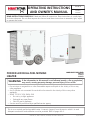 1
1
-
 2
2
-
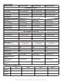 3
3
-
 4
4
-
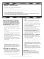 5
5
-
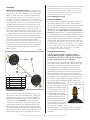 6
6
-
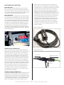 7
7
-
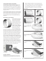 8
8
-
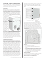 9
9
-
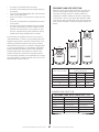 10
10
-
 11
11
-
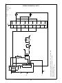 12
12
-
 13
13
-
 14
14
-
 15
15
-
 16
16
-
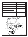 17
17
-
 18
18
-
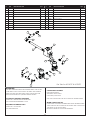 19
19
-
 20
20
-
 21
21
-
 22
22
-
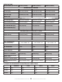 23
23
-
 24
24
-
 25
25
-
 26
26
-
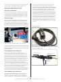 27
27
-
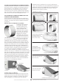 28
28
-
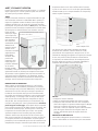 29
29
-
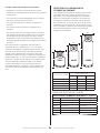 30
30
-
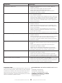 31
31
-
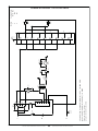 32
32
-
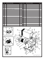 33
33
-
 34
34
-
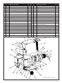 35
35
-
 36
36
-
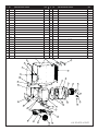 37
37
-
 38
38
-
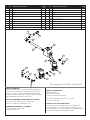 39
39
-
 40
40
-
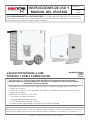 41
41
-
 42
42
-
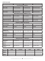 43
43
-
 44
44
-
 45
45
-
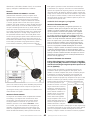 46
46
-
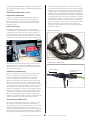 47
47
-
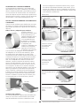 48
48
-
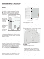 49
49
-
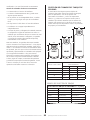 50
50
-
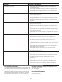 51
51
-
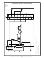 52
52
-
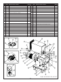 53
53
-
 54
54
-
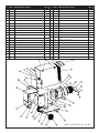 55
55
-
 56
56
-
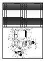 57
57
-
 58
58
-
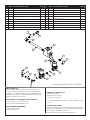 59
59
-
 60
60


HeatStar F109120 El manual del propietario
- Tipo
- El manual del propietario
en otros idiomas
- français: HeatStar F109120 Le manuel du propriétaire
- English: HeatStar F109120 Owner's manual
Artículos relacionados
Otros documentos
-
Mr. Heater 2 x MH-F270700 Manual de usuario
-
DeWalt DXH125FAVHC Guía del usuario
-
-
Dyna-Glo GBF30DTDG-2 Guía de instalación
-
-
-
-
Honeywell SV2 Series Valve Programming Tool HMITOOL-000 Instrucciones de operación
-