
- -.-PARTS CATALOG
c5
c
Generafors
Model
RGD3700
@ FUJI HEAVY INDUSTRIES LTD.

HOW TO USE THIS PARTS CATALOG
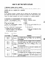
1. Reference numbers with an asterisk
Reference numbers marked with an asterisk indicate that the particular part is
available only as a complete set or assembly.
Example :
If the reference number is marked with an asterisk and the description of the
part states that certain items are included, this means that those included items
cannot be ordered separately and must be purchased as a complete assembly.
2.
Description of interchangeability and execution columns
Example : Interchangeability column
Example : Execution column
Items interchangeable between the
new and old parts.
TX Items not interchangeable between
d the new and old parts.
Items conditionally interchangeable
3 between the new and old parts
which are subject to the description
in the execution column.
For use for Serial No. up to
o1oooo.
Serial No.
For use for Serial No. from
Example :
Interchangeable
Part Number
Part B
Part A
Part C
Part B
Part A
I
Part A
I
Part B
Part B
Part A
t
3
3
3
Execution Explanation
020000 -
020000 -
015000 -
020000 -
- 030000
020000 -
This indicates that Part A changed to Part 6 for generators
with serial numbers from 20000, and that they are
interchangeable.
This indicates that Part A cahnged to Part B for generators
with serial numbers from 15000, and that they are not
interchangeable. Also, Part B changed to Part C for
generators with serial numbers from 20000 and that they
are interchangeable.
This indicates that Part A is a new part for generators with
serial numbers with from 20000.
This indicates that Part B is no longer used for generator
with serial numbers from 30001.
This indicates that Part A changed to Part B for generators
with serial numbers from 20000, and that they are
conditionally interchangeable. (See NOTE described at the
end of the section.)

c
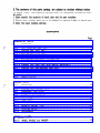
3. The contents of this parts catalog are subject to revision without notice.
TO INSURE PROMPT AND ACCURATE SERVICE. ALSO THE FOLLOWING INFORMATION MUST
BE GIVEN.
1. State exactly the quantity of each part and its part numbers.
2. Clearly state whether parts are to be shipped by express, freight or parcel post.
3. State the exact mailing address.
CONTENTS
Page
GENERATOR PARTS
FIG. 1 GENERATOR
.......................................................................
1
FIG. 2
PIPE FRAME and FUEL TANK
....................................................
3
FIG. 3- 1 CONTROL BOX (220V, 240V)
......................................................
5
FIG. 3 - 2 CONTROL BOX (110V, 120V)
.....................................................
11
FIG. 3-3 CONTROL BOX (110V/220V)
.....................................................
17
FIG. 3 -4 CONTROL BOX (U.K
50Hz- 110V,220V. BS>
.....................................
.. 21
FIG. 3 - 5 CONTROL BOX (GERMANY. 50Hz- 220V)
.........................................
25
FIG. 3 - 6 CONTROL BOX (50Hz- 220V. WITH SPECIAL
RECEPTACLE)
......................
29
FIG. 3 - 7 CONTROL BOX (SWITZERLAND, 50Hz - 220V)
.....................................
33
FIG. 3 -8 CONTROL BOX (AUSTRALIA. 50Hz- 240V)
........................................
37
FIG. 3 - 9 CONTROL BOX (FRANCE, 50Hz- 220V)
...........................................
41
FIG. 4
RECOIL STARTER
.................................................................
45
ENGINE PARTS
FIG. 5
CRANKCASE
......................................................................
47
FIG. 6
CYLINDER and CYLINDER HEAD
.................................................
51
FIG. 7
CRANKSHAFT and PISTON
.......................................................
55
FIG. 8
CAMSHAFT and GOVERNOR
......................................................
57
FIG. 9
FUEL INJECTION PUMP and NOZZLE
.............................................
61
FIG. 10 FUEL FILTER
.....................................................................
63
FIG. 11
AIR CLEANER, MUFFLER and CYLINDER
BAFFLE
.................................
65
FIG. 12 MUFFLER (SPECIAL TYPE)
.......................................................
67
FIG. 13 STARTING MOTOR
................................................................
69
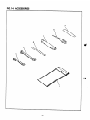
FIG. 14 ACCESSORIES
.....................................................................
71
OPTIONAL PARTS
FIG. 15 WHEEL, HANDLE and HANGER
. . . . . . . . . . . . . . . . . . . . . . . . . . . . . . . . . . . . . . . . . . . . . . . . . . .
73

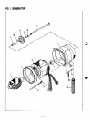
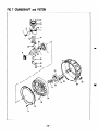
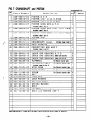
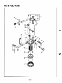
FIG. 1 GENERATOR
-1-

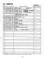
FIG.
1 GENERATOR
Ref.
No.
Parts Number
Description
lnterdrarysabili
ty
T t
Executiarl
I
I
21
385-50528-08
ROTOR, 1.
camp
Incld0s
i&w
2
1
I
2
354-58204-08
BALL BEARING
(8205-2RS)
1
c
I
I I
I I
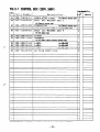
Ben orderiw parts : Always give the k&l, Specification and Serial Nurber of Generator.

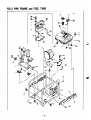
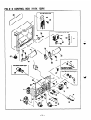
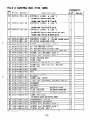
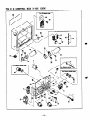
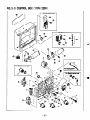
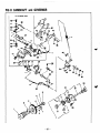
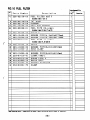
FIG. 2 PIPE FRAME and FUEL TANK
For Ektric starter type
%-69
36
40
36
39
I
31
13
17

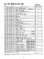
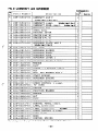
FIG. 2 PIPE FRAME and FUEL TANK
385-58063-08 1 PIPE FRAME.compl.
ercrlption
385-58582-08 1 SIDE PLATE.compl. Includes itea 3
I
ll
I
I
I
31 385-59176-08 [ LABEL (RGD3700)
1 1
1 41 011-00600-80 1 BOLT and WASHER ASS’Y
1 61 359-59933-08 1 FLANGE BOLT
I 21
I 71 385-54826-08 I ENGINE BASE. compl. I
11
I 81 228-15023-03 I VIBRATION ISOLATOR I 21
91 002-27100-00 f NUT
I 4
101 228-15024-03 I STOPPER
I 2
11 001-11081-20 I BOLT and WASHER ASS’Y
I 4
1 I
I
121 001-86085-00 t BOLT
I 4
I
I
I
131 002-37080-00 1 FLANGE NUT
I 9
14 385-54827-08 GENERATOR BASE, camp 1. 1
15 385-57053-08 RUBBER MOUNT 1
I I
161 001-13082-50 I BOLT and WASHER ASS’Y
I
I 2
I I
I
171 003-10080-00 1 WASHER
I
4
I
I I
181 385-54399-08 I EARTH CORD
I 1
19 228-60701-01 FUEL TANK, compl. 1
20 064-13600-10 FUEL FILTER 1
I
I
211 391-94001-03 I LABEL, brushless
I I
25) 356-59020-08 1 LABEL,fuel only
I
1 1
I
1 1
r-g 5i5-5
9248-08 I LABEL, fuel only
r-2d 3~s 5 - 5
9137-08 1 LABEL,caution
For FRANCE I 1 1
I 11
-26 385-59247~-08 LABEL, caution For FRAFCE 1
27 043-04300-15 FUEL TANK CAP, compl. 1
28 064-80007-00 FUEL GAUGE, compl. 1
-
rgyTl 4-y ~~
0500-40 1 SCREW,counter head
I 21
i.
13DlQ56-57045-08 1 RUBBER VIBRATION ISOLATOR
I
41
1 fill -385-54828-08 I BATTERY BASE For Electric starter type 1 I I
011-00600-20
FLANGE BOLT For Electric starter type 2
356-54316-08
BATTERY BOLT
For Electric starter type 2
002-17060-00 NUT
For Electric starter type 2
003-20060-00
SPRING WASHER
For Electric rtarter type 2
385-54382-08
BATTERY ANGLE
For Electric starter type 1
385-54383-08
BATTERY CORD (+)
For Electric starter type 1
385-54384-08
BATTERY CORD (-1
For Electric starter type 1
065-10000-90
BATTERY (NS40ZL)
For Optional parts 1
385-54416-08
BATTERY SUPPORT
For Electric starter type 2
41 376-39100-01 SCREW and WASHER ASS’ Y 1
42 056-60001-70 CLAMP 1
l&en ordering parts ; Always give the Haiel, Specification and 6eriaI Nurber of Generator.
-4-

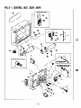
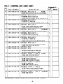
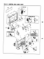
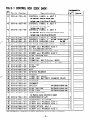
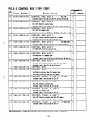
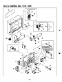
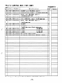
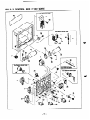
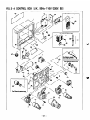
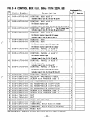
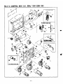
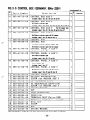
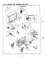
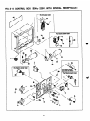
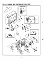
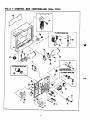
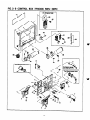
FIG. 3- 1 CONTROL BOX (22OV, 24OV)
kor Oil sensor type
For Electric stmer type

.
-.
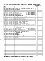
FIG. 3-l CONTROL BOX (22OV,
24OV)
lntardmunmhi I i t~v
z
Parts Number
lo.
Description IJ’ t
-
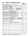
11 385-40606-08 CONTROL BOX ASS’ Y
For 220V 1
Includes items 2 thru 23, 25 thru 27, 33 thru 40 ad 46
-
11
385-40887-08 CONTROL BOX ASS’ Y 1
For 5ONz-2WV, Electric starter type
Includes iti 2 thru 23,25,27 thru 30, 33 thru 43, 46, 47
-
11
385-40688-08 CONTROL BOX ASS’ Y 1
For 5Oik22OV, Oi 1 sensor type
lncludea itgls 2 thru 23,25 thru 27.33 thru 40, 44 thru 47
-
11 385-40689-08 CONTROL BOX ASS’ Y 1
For 22oV, Electric starter type with Oil sensor
I Includes iteas 2 thru 23, 25 ad 28 thru 47
-
B 1 ’ 385-40607-08 CONTROL BOX ASS’ Y For!%Ez-240V 1
Includea iteas 2 thru 23, 25 thru 27, 33 thru 40 and 45
A--
11 385-40690-08 CONTROL BOX ASS’ Y 1
For 503~24OV, Electric starter type
lncludea itees 2 thru 25, 27 thru 30, 33 thru 43,48 and 47
r
El 385-40691-08 CONTROL BOX ASS’ Y 1
For xltlz-24OV, Oil sensor type
lncludea iteur 2 thru 27, 33 thru 40 and 44 thru 47
. /
1
El
385-40692-08
CONTROL BOX ASS’ Y
For 5Mz-24OV, Electric starter type rith Oil aenaor
lncludeaiti2thru25and28thru47
1 386-43086-08 CONTROL BOX
1 386-43096-08 CONTROL BOX
For Electric starter type, Oil sensor type
For Electric starter type with Oil sensor
12
385-41434-08
CONTROL PANEL A ASS’ Y For 220V
lncludea items 3 thru 23 and 25 thru 27
12 385-41724-08 CONTROL PANEL A ASS’ Y
FOF 2WV, Electric starter type
Includes item8 3 thru 23, 25, 27 and 28
$2
385-41434-08
CONTROL PANEL A ASS’ Y
For 2WV, Oil 8en8or type
Includes itees 3 thru 23, 25 thru 27
i
i
r
-i
L
1
*2
385-41725-08
CONTROL PANEL A ASS’ Y 1
For 2WV, Electric starter type with Oil sensor
Includes iteas 3 thru 23, 25 and 28 thru 32
s2
385-41435-08
CONTROL PANEL A ASS’ Y
For !iOllz-24OV 1
Includes iters 3 thru 27
Len ordering parta ; Always give the lkdel, Specification ad Serial Nuaber of Generator.
-6-

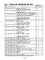
FIG. 3- 1 CONTROL BOX (22OV, 24OV)

FIG. 3- 1 CONTROL BOX
(22OV, 24OVI
Interc+geability
I 111
Parts Number
Description
CONTROL PANEL A ASS’ Y
h )ti
‘t
Execution
1
For 50&24OV, Electric etarter type
lnclades iteas 3 thru 25 and 27 thru 33
CONTROL PANEL A ASS’ Y
For 5Otlz-249V, Oil a-r type
Includes iteas 3 thru 27
82
I
385-41435-08
c
l 2
385-41727-08
CONTROL PANEL A’ ASS’ Y
I 11
2 385-43893-08
821 385-43494-08
31 385-45651-08
3 389-45656-08
5 004-35030-60
6 320-75112-08
7 378-45736-08
10 004-35041-00
15 320-59855-08
18 320-59860-08
For Wtlz-24OV, Electric starter type with Oil sensor
1 I
lnclude~ iteas 3 thru 25 aad 28 thru 32
I I
CONTROL PANEL A For 229V
1
CONTROL PANEL A
For 24OV Includes i tea 24 1
NO-FUSE BREAKER (14A)
For 229V
1
c
c
NO-FUSE BREAKER (12A)
I
For 249V
I 1
4
SCREW and WASHER ASS’ Y
2
AC VOLTMETER (3OOV) 1
AC RECEPTACLE (25OV-15A)
SCREW and WASHER ASS’ Y
FUSE HOLDER (DC)
I
FUSE (1 OA)
I 1
171 363-45701-08
TERMINAL BOLT (Color:RED)
I 11
181 363-45700-08
TERMINAL BOLT(Color:BLACK) I
11
WING NUT
1 1
E
19 353-49901-08
W 356-49907-08
211 353-49902-08
22 332-00050-08
23 353-49903-08
SCREW 1 1
NUT 1
SPRING WASHER 2
WASHER 1 1
241
353-49035-08
LABEL (AC 24OV)
I
II
E
1
LABEL (DC BATTERY CHARGE ONLY) 1 1 25 363-49091-08
26 389-47552-08
27 355-57509-08
28 066-00002-50
GROMMET
I 11
I
GROMMET I 1
SW1 TCH
I
For Electric starter type I 1
291 385-45517-08 FUSE HOLDER
For Electric starter type I 1 I
WI 385-45518-08 FUSE (15A)
For Electric starter type I 1 I
32
351-45302’-08
I
LAMP, warning
I 11
k
For Electric starter type with Oil seasor
CONDENSER (2OccF)
CONDENSER BRACKET
SCREW and WASHER ASS’ Y
SCREW and WASHER ASS’ Y
DIODE STACK ASS’ Y
SCREW and WASHER ASS’ Y
331 385-47541-08 2
4
35 380-47531-08
36 004-35041-00
37 389-59989-08
38 353-45804-08
39 353-59949-08
_
ordering
parts ; Aluaya
give the Nodel, Specification and Serial Nuaber of Generator.
3
1
1
I
1 1
-8-

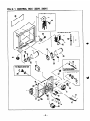
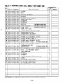
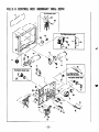
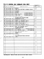
FIG. 3- 1 CONTROL BOX (22OVn 24OV)
For Ektrii rtu
- 19
49
-9-

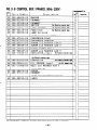
FIG. 3- 1 CONTROL BOX (22OV, 24OV)
Ref.
No.
Parts Number
Description
lnterchaageability
0’ ty
Execution
1 I
41 228-71920-01
REGULATOR, compl. For
Electric starter
type 1
42 001-11062-50
BOLT and WASHER ASS’
Y
2
I I
For Efectric starter typa
43 385-47321-08
CONNECTOR
For
Electric starter
type 1
44 228-76001-01
01 L SENSOR,
camp
1. For
Oil
aeaaor type
1
45 001-11063-50
BOLT and WASHER
ASS’
Y
2
For Oil BBnsor type
46 353-49904-08
SCREW
8
47 385-57511-08
GROMMET
1
For Oil aeaaor type or Electric starter type
48 385-59227-08
LABEL
For
5Oik226V
1
48 385-59228-08
LABEL
For
505z-24OV
1
48 385-59229-08
LABEL
For
66kZ26V
1
49 320-75122-08
AC PLUG (25OV-15A)
2
I I
I I
I
Uhea o&riag parta ; Alaaya give the Mel, 6pecificatfoa aad Serial Nnabar of (leaerator.
-l0-

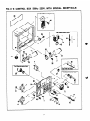
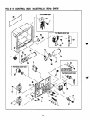
FIG. 3- 2 CONTROL BOX (11 OV,
12OV)
r
For Oil sensor type
J
For Electric startar type
3

FIG. 3- 2 CONTROL BOX (11 OV.
12OV)
mbility
iz
lo.
-
I1
Parts Number
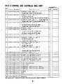
385-40608-08
Dercription
CONTROL BOX ASS’ Y
For 1lOV
Iacluder iteea 2 thru
23, 25 tbru 27,
33 thru 40 and 46
Exeadon
ty
1
1
1
1
1
1
1
1
1
1
1
1
1
1
1
El
385-40693-08 CONTROL BOX ASS’ Y
For llOV, Electric starter type
Includes itees 2 thru 23.25.27 thru 30. 33 thru 43. 46. 47
CONTROL BOX ASS’ Y
For llOV, Oil senwx type
Includes iteur 2 thru 23.25 thru 27,33 thru 40, 44 thru 47
CONTROL BOX ASS’ Y
For 1109, Electric starter type with Oil sensor
Includes itew 2 thru 23, 25 and 23 thru 47
CONTROL BOX ASS’ Y For 6OEz-1ZOV
Includes im 2 thru 23, 25 thru 27, 33 thru 40 and 46
CONTROL BOX ASS’ Y
For 60&120V, Electric starter type
Includes iteu, 2 thru 23,25,27 thru 30, 33 thru 43, 46, 47
385-40694-08
El
385-40695-08
385-40611-08
385-40696-08
*l 385-40697-08
CONTROL BOX ASS’ Y
For 6OiIz-l%JV, Oil wmsor type
Includee im 2 thru 23,25 thru 27,33 thru 40, 44 tbru 47
*1
365-40898-08
CONTROL BOX ASS’ Y
For 6CHIz-12OV, Electric starter type with Oil sensor
Includes itees 2 thru 23, 25 and 23 thru 47
CONTROL BOX
CONTROL BOX
For Electric starter type, Oil sensor type
For Electric starter type with Oil sensor
CONTROL PANEL A ASS’ Y
For 1lOV
Includea iti 3 thru 23 and 25 thru 27
CONTROL PANEL A ASS’ Y
For llOV, Electric starter type
Includes items 3 thru 23, 25, 27 and 28
1
386-43086-08
388-43096-08 I
385-41436-08
*i
385-41728-08
385-41436-08
CONTROL PANEL A ASS’ Y
For llOV, Oil sensor type
Includes items 3 thru 23 and 25 thru 27
CONTROL PANEL A ASS’ Y
For llOV, Electric starter type with Oil sensor
Includes iteea 3 thru 23, 25 and 28 thru 32
*i
*:
385-41729-08
CONTROL PANEL A ASS’ Y
For 6OlIz-120V
Includes itees 3 thru 23 and 25 thru 27
385-41439-08
men ordering parts ; Always give the Hodel, Specification and Serial Number of Generator.
- 12-

FIG. 3- 2 CONTROL BOX (11 OV,
12OV)
For Oil sensor type
1
For Electric starter type
30
29
For Electric starter typm

.
.
.
FIG. 3- 2 CONTROL BOX (11 OV, 12OV)
II
~terchauaeahilitu
Parts Number
Description
+
385-41730-08
CONTROL PANEL A ASS’ Y
For 60&120V, Electric starter type
Includes itewa 3 thru 23. 25. 27 and 26
t:
i
385-41439-08
CONTROL PANEL A ASS’ Y
For 3OJk12OV, Oil aeuaor type
Includes itewa 3 thru 23 aad 25 thru 37
i
385-41731-08
CONTROL PANEL A ASS’ Y
i
For 50&12OV, Electric starter type with Oil aeusor
Inciudea itewa 3 thru 23. 25 aud 23 thru 32
385-43395-08
385-43396-08
385-45661-08
004-35030-60
320-75127-08
378-45737-08
357-45703-08
004-35041-00
379-49933-08
320-59855-08
320759860-08
363-45701-08
363-45700-08
353-49901-08
356-49907-08
353-49902-08
332-00050-08
353-49903-08
353-49037-08
363-49091-08
389-47552-08
355-57509-08
066-00002-50
385-45517-08
385-45518-08
351-45302-08
CONTROL PANEL A
For 1lOV
CONTROL PANEL A
For 12OV Iacludea itea 24
NO-FUSE BREAKER (27A)
SCREW and WASHER ASS’ Y
AC VOLTMETER (15OV)
AC RECEPTACLE (125V-15Al
AC RECEPTACLE (125V-30A, ‘l’VISl’iAX6)
SCREW and WASHER ASS’ Y
SCREW and WASHER ASS’ Y
FUSE HOLDER (DC)
FUSE (1 OA)
TERMINAL BOLT (Color : RED)
TERMINAL BOLT(Color:BLACK)
WING NUT
SCREW
NUT
SPRING WASHER
WASHER
LABEL (AC 12OVJ
LABEL(DC BATTERY CHARGE ONLY)
GROMMET
GROMMET
SWITCH
For Electric starter
FUSE HOLDER
For Electric starter type
FUSE (15A)
For Electric starter type
LAMP, warning
For Electric starter type with Oil sensor
CONDENSER (20&F)
CONDENSER BRACKET
SCREW and WASHER ASS’ Y
SCREW and WASHER ASS’ Y
DIODE STACK ASS’ Y
i
i
i
'i
i
i
i
'i
z
i
i
i
i
i
i
i
-i
i
i
i
i
i
i
i
i
i
385-47541-08
380-47531-08
004-35041-00
389-59989-08
353-45804-08
-2
7
-
?
i
i
II I
+
Execution
I
II
H---l
Whew ordering parts : Always give the Model, Specification and Serial Nuwber of Generator.
- 14-

FIG. 3- 2 CONTROL BOX (11 OV, 120V)
For Oil sensor WPO
For Electric starter type
m
29
1

FIG. 3- 2 CONTROL BOX (1 lOV, 12OV)
Int~whm~h~fit”
give the
Specification Serial Auaber Generator.
-16-

FIG. 3- 3
CONTROL BOX ( 11 OV /
220V)

-.
FIG. 3- 3 CONTROL BOX (11 OV/
22OVl
Ref.
Parts Number
NO.
Description
Q’ t
Bl 385-40609-08
CONTROL BOX ASS’ Y
For llOV/22OV 1
Includes im 2 thrw 27, 33 tbzw 40 and 46
81 385-40699-08 CONTROL BOX ASS’ Y 1
For llOV/22OV, Electric starter type
Includes itewa 2 thru 25, 27 thru 39, 33 thru 43,46 and 47
@l 385-40700-08 CONTROL BOX ASS’ Y 1
For llOV/22OV, Oil sensor type
Includwa itewa 2 thru 27, 33 thru 40 and 44 thru 47
rl 385-40701-08 CONTROL BOX ASS’ Y 1
For llOV/22oV, Electric starter type with Oil sensor
lncltxlea iters 2 thru 25 and 28 thru 47
1 386-43086-08 CONTROL BOX 1
1 386-43096-08 CONTROL BOX 1
For Electric starter type, Oil aenaor type
For Electric starter type with Oil aenaor
*2 385-41437-08
CONTROL PANEL A ASS’ Y
For llOV/22OV 1
For llOV/22OV, Electric starter type
For llOV/22OV, Oil aenaor type
For llOV/22OV, Electric starter type with Oil sensor
10 004-35041-00 SCREW and WASHER ASS’ Y :
11 379-49933-08 SCREW and WASHER ASS’ Y :
12 004-35041-00 SCREW and WASHER ASS’ Y :
15 320-59855-08 FUSE HOLDER (DC)
1
16 320-59860-08 FUSE (1 OA)
1
17 363-45701-08 TERMINAL BOLT (Co 1 or : RED)
18 363-45700-08 TERMINAL BOLT(Color:BLACK)
19 353-49901-08 WING NUT
/hen ordering parts ; Always give the Hodel, Specification and Serial Nuwher of Generator.
- 18-

FIG. 3 - 3
CONTROL
BOX ( 11 OV /
22OW
For Oil sensor type
For Electric starter typs

FIG.3-3 CONTROL BOX
(llOW22OV)
c
c
Interchangeability
Ref.
NO.
Parts Number
Description
1’ t)
Executiou
20 356-49907-08
SCREW
1
21 353-49902-08
NUT
22 332-00050-08
SPRING WASHER
353-49903-08
1 WASHER
24
356-45612-08
SWITCH. full power
25
363-49091-08
LABELCDC BATTERY
CHARGE
ONLY)
28 389-47552-08
GROMMET
27 355-57509-08
GROMMET
28 066-00002-50 SWITCH
For Electric
starter type
29 385-45517-08
FUSE HOLDER For Electric starter type
30 385-45518-08 FUSE (15A)
For Electric starter type
32 351-45302-08 LAMP, warning
For Electric starter type with Oil sensor
33
385-47541-08
CONDENSER (20uF)
35 380-47531-08
36 004-3504 l-00
37 389-59989-08
38 353-45804-08
39 353-59949-08
41 228-71920-01
42 001-11062-50
CONDENSER BRACKET
SCREW and WASHER ASS* Y
SCREW and WASHER ASS’ Y
DIODE STACK ASS’ Y
SCREW and WASHER ASS’ Y
REGULATOR, compl. For Electric starter type
BOLT and WASHER ASS’ Y
For Electric starter type
385-47321-08
CONNECTOR For Electric starter type
228-76001-01
01 L SENSOR, camp 1. For Oil sensor type
001-11063-50
BOLT and WASHER ASS’ Y
For Oil sensor type
353-49904-08 SCREW
47 385-57511-08
GROMMET
For Oil sensor type or Electric starter type
365-59233-08 1 LABEL
For 5OHz-1 lOV/22OV
385-59234-08 1 LABEL
For 8OHz-1 lOV/22OV
491 320-75176-08 1 AC PLUG(125V-15A)
501 353-45705-08 1 AC PLUG(250V-30A.TWIST LOCK)
511 320-75176-08 1 AC PLUG(250V-15A)
1
2
1
1
1
1
1
1
1
1
1
8
1
Uhen ordering parts ; Always give the Model, Specification and Serial Nuwber of Generator.
-20-

FIG. 3- 4 CONTROL BOX (U.K., 50Hz- 11
OV/ 22OW
BS)
I
34
For Electric starter type
I
For Oil sensor type
I
0-l ‘. .44
For Electric starter typr
r
For Electric starter type
A-
l
-21-

FIG. 3-4 CONTROL BOX (U.K., 50Hz- llOV/22OV, BS)
seability
Inter&
Ref
No.
*l
-
*I
Parts Number
Description
Execution
I I
CONTROL BOX ASS’ Y
1
385-40702-08
Includes itews 2 thru 27. 33 thru 40 and 46
CONTROL BOX ASS’ Y
1
For Electric starter type
Includes itews 2 thru 25,2’7 thru 30, 33 thru 43, 46 and 47
CONTROL BOX ASS’ Y
For Oil sensor type 1
Includes itews 2 thru 27, 33 thru 40 and 44 thru 47
385-40703-08
*l
-
*l
-i
-i
-
*2
-
*2
-
22
385-40704-08
CONTROL BOX ASS’ Y
For Electric starter type with Oil sensor
Includes itews 2 thru 25 and 2% thru 47
385-40705-08
CONTROL BOX
I 11
386-43097-08
386-43098-08
CONTROL BOX
For Electric starter type, Oil sensor type
For Electric starter type with Oil sensor
1
r
385-41734-08
CONTROL PANEL A ASS’ Y
Includes itews 3 thru 13, 24, 26 and 27
CONTROL PANEL A ASS’ Y
For Electric starter type
Includes itews 3 thru 13, 24, 27 and 28
CONTROL PANEL A ASS’ Y
For Oil sensor type
Includes itews 3 thru 13, 26 and 27
385-41735-08
385-4 1734-08
*2 385-41736-08 CONTROL PANEL A ASS’ Y
For Electric starter type with Oil sensor
Includes itees 3 thru 13, 24 and 28 thru 32
1
2
385-43471-08
CONTROL PANEL A
I 11
3 356-45642-08
NO-FUSE BREAKER (14AX21
I 11
5 004-35030-80 SCREW and WASHER ASS’ Y
I 41
6 320-75127-08
AC VOLTMETER (15OVl
I 11
7
353-45725-08
AC RECEPTACLE (11 OV-16A)
I 11
8
353-45731-08
AC RECEPTACLE (11 OV-32A)
I 11
9 353-45727-08
iii
363-49933-08
11
380-49944-08
12
002-17040-00
-ii
002-17050-00
15
320-59855-08
-ii
320-59860-08
17
363-45701-08
Is
363-45700-08
NUT 4’
FUSE HOLDER (DC) 1
FUSE (1 OA) 1
TERMINAL BOLT (Co 1 or : RED)
1
TERMINAL BOLT(Color:BLACK)
11-1
19
353-49901-08
WING NUT 1 11
A
#en ordering parts ;
Always give the kdel, Specification and Serial Number of Generator.
-
22
-

FIG. 3- 4 CONTROL BOX (U.K., 50Hz- 1 lOV/ 22OV, BS)
-
23
-

r
\
c
0
201 358-49907-08 1 SCREW
211 353-49902-08 1 NUT
221 332-00050-08 1 SPRING WASHER
231 353-49903-08 1 WASHER
241 355-45613-08 1 SWITCH. full Dower I 11
25 353-49036-08 LABEL (DC OUT) 1
26 389-47552-08 GROMMET 1
27 355-57509-08 GROMMET 1
281 066-00002-50 1 SWITCH For Electric starter type I 1 I
291 385-45517-08 1 FUSE HOLDER
For Electric starter type 1 1
361 385-45518-08 ] FUSE(15A)
For Electric starter type 1 1
32 351-45302-08
I
LAMP, warning 1
For Electric starter tvDe with Oil sensor I I
331 385-47541-08 1 CONDENSER(20fiF)
I 21
351 380-47531-08 1 CONDENSER BRACKET
I
41
381 004-35041-00 I SCREW and WASHER ASS’Y I 31
37 389-59989-08 SCREW and WASHER ASS’ Y 1
36 353-45804-08 DIODE STACK ASS’ Y 1
39 353-59949-08 SCREW and WASHER ASS’ Y 1
I I
41 228-71920-01 REGULATOR, camp 1. For Electric starter type 1
42 001-11062-50 BOLT and WASHER ASS’Y 2
I
For Electric starter type
I I
I
I
431 385-47321-08 1 CONNECTOR
For Electric starter type I 1
FIG. 3- 4 CONTROL BOX (UK., SOHz- 1 lUv/220v, Bs)
Interchaageability
Ref.
Parts Number
No.
Description
P’ ty Execution
I
I
I I
&en ordering parts : Always give the Hodel, Specification and Serial Number of Generator.
441 228-76001-01 I OIL SENSOR, compl. ForOilsensortype
I 11
45 001-11063-50
BOLT and WASHER ASS’ Y 2
For Oil sensor type
461 353-49904-08 1 SCREW
47 385-57511-08 GROMMET
1
For Oil sensor type or Electric starter type
I I
-481 385-59233-08 1 LABEL
I 11
491 353-45726-08 1 AC PLUG(llOV-16Al
I2
50 353-45732-08 AC PLUG (llOV-32A) 1
51 353-45728-08 AC PLUG (240V-16A) 1
I
I
I
-24-

FIG. 3- 5 CONTROL BOX (GERMANY, 50Hz-
22OV)
For Electric atarter type
-
25
-

FIG. 3- 5 CONTROL BOX (GERMANY. 5UHz- 22OV)
Interchhili tv
Ref.
Parts Number
No.
Description
P’ ty
Execution
*1 385-40710-08
CONTROL BOX ASS’ Y
1
Includes itews 2 thru 27, 33 thru 40 and 48
*l 385-40711-08
CONTROL BOX ASS’ Y
1
For Electric starter type
Includes itess 2 thru 25,27 thru 30, 33 thru 43, 48
and 47
*1 385-40712-08
CONTROL BOX ASS’ Y For Oil sensor type 1
Includes itews 2 thru 27, 33 thru 40 and 44 thru 47
*1 385-40713-08
CONTROL BOX ASS’ Y
1
For Electric starter type with Oil sensor
Includes iteas 2 thru 25 and 28 thru 47
1 386-43086-08
CONTROL BOX
1
1 386-43096-08
CONTROL BOX
1
For Electric starter type,Oil sensor type
For Electric starter type with Oil sensor
*2 385-41740-08
CONTROL PANEL A ASS’ Y 1
Includes im 3 thru 27
*2 385-41741-08
CONTROL PANEL A ASS’ Y
1
For Electric starter type
Includes itews 3 thru 25, 27 and 28
$2
385-41740-08 CONTROL PANEL A ASS’ Y 1
For Oil sensor type
Includes itews 3 thru 27
82 385-41742-08
CONTROL PANEL A ASS’ Y
1
For Electric starter type with Oil sensor
when ordering parts ; Always give the Model, Specification and Serial Nuder of Generator.
-26-

FIG. 3- 5 CONTROL BOX (GERMANY, 50Hz- 22OV)
-
27
-

.
__-.
-._
(r
FIG. 3- 5 CONTROL BOX (GERMANY, 50Hz-
22OV)
Interchaageabilitv
Ref.
I I
Parts Number
No.
Description
bl I
‘t
$
Execution
1 I I
231 353-49903-08 1 WASHER
Ill 1
I
I
251 383-49091-08 1 LABEL(DC BATTERY CHARGE ONLY) 11
1281 389-47552-08 1 GROMMET
I 11
1271 355-57509-08 I GROMMET
I
11
1281 066-00002-50 I SWITCH
For Electric starter type
I
11
1291 385-45517-08 I FUSE HOLDER
For Electric starter type
I
11
30 385-45518-08 FUSE (15A) For Electric starter type 1
32 351-45302-08 LAMP, warning 1
For Electric starter type with Oil seasor
33 385-47541-08 CONDENSER (2OrcF) 2
35 380-47531-08 CONDENSER BRACKET 4
36 004-35041-00 SCREW and WASHER ASS’ Y 3
37 389-59989-08 SCREW and WASHER ASS’ Y 1
38 353-45804-08 DIODE STACK ASS’ Y 1
39 353-59949-08 SCREW and WASHER ASS’ Y 1
1411 228-71920-01 1 REGULATOR, cdmpl. ForElectricstartertype] 11
42 001-11062-50
I I
I
BOLT and WASHER ASS’ Y 2
For Electric starter type I I
43 385-47321-08 CONNECTOR For Electric starter type 1
44 228-78001-01 OIL SENSOR, compl. For Oil seasor type 1
45 001-11063-50 BOLT and WASHER ASS’ Y 2
For Oil sensor type
46 353-49904-08 SCREW 8
47 385-57511-08 GROMMET 1
For Oil sensor type or Electric starter type
48 385-59227-08 LABEL 1
c
Uhea ordering parts ; Always give the Hodel, Specification and Serial Number of Ceaerator.
- 28 -

FIG. 3- 6 CONTROL BOX (50Hr- 22OV, WITH SPECIAL RECEPTACLE)

FIG. 3- 6 CONTROL BOX (50Hr 22OV. WITH SPECIAL RECEPTACLE)
Ref.
No.
Parts Number
Description
Interchang&ility
Y
Execution
*l 385-40714-08
I
CONTROL BOX ASS’ Y
1
Includes iters 2 thru 27, 33 thru 40 and 46
I
385-40715-08
CONTROL BOX ASS’ Y
For Electric starter type
1
385-40716-08
*l 385-40717-08
Includes i-s 2 thru 25,2’7 thru 30, 33 thru 43, 46 and 47
CONTROL BOX ASS’ Y
For Oil sensor type 1
Includes iters 2 thru 27, 33 thru 46 and 44 thru 47
CONTROL BOX ASS’ Y
1
For Electric starter type with Oil sensor
Includes iters 2 thru 25 and 28 thru 47
CONTROL BOX
1
CONTROL BOX
1
For Electric starter type,Oil ssesor type
.
For Electric starter type with Oil sensor
CONTROL PANEL A ASS’ Y I
Includes itsss 3 thru 27
E
11 386-43086-08
1 386-43096-08
L
*2 385-41743-08
L
82 385-41744-08
CONTROL PANEL A ASS’ Y
1 1
For Electric starter type
Includes iteas 3 thru 25, 27 and 28
82
I
385-41743-08 CONTROL PANEL A ASS’ Y
For Oil sensor type
1
Includes iteas 3 thru 27
*2
385-41745-08 CONTROL PANEL A ASS’ Y
1 l
For Electric starter type with Oil sensor
Includes itees 3 thru 25 and 28 thru 32
I
I
CONTROL PANEL A
1 1
NO-FUS-Ed BREAKER (20A)
6 320-75112-08
7 358-45718-08
10 363-49930-08
13 002-17040-00
I
,
1
t
I
NUT
I 4
c
c
,
151 320-59855-08
FUSE HOLDER (DC)
t-
-161 320-59860-08
171 363-45701-08
FUSE (1 OA)
1
TERMINAL BOLT (Co 1 or : RED) 1
TERMINAL BOLT(Color:BLACKl 1
WING NUT 1
SCREW 1
NUT 1
1
18 363-45700-08
19 353-49901-08
F
201
356-49907-08
21
353-49902-08
22 332-00050-08
SPRING WASHER
1 2
I
231 353-49903-08
WASHER
Ii
Rten ordering parts
Always give the kdel, Specification and Serial #unbar of Generator.
-30-

FIG. 3- 6 CONTROL BOX (50Hz- 22OV, WITH SPECIAL RECEPTACLE)

FIG. 3- 6 CONTROL 60X (50Hz-220V, WiTH SPECIAL RECEPTACLE)
25 363-49091-08
LABEL (DC BATTERY
CHARGE
ONLY) 1
26 389-47552-08 GROMMET 1
27 355-57509-08 GROMMET 1
b
281 066-00002-50 1 SWITCH
For Electric starter type 1
291 385-45517-08 1 FUSE HOLDER
For Electric starter type 1
1301 385-45518-08 1 FUSE (15Al
For Electric starter type 1 1 1
32 351-45302-08
I I
LAMP, warning
1
For Electric starter type with Oil sensor
I I
1331 385-47541-08 1 CONDENSER(20fiFl
351 380-47531-08 1 CONDENSER BRACKET
I 4
%I 004-35041-00 1 SCREW and WASHER ASS’ Y
13
37 389-59989-08 SCREW and WASHER ASS’ Y 1
38 353-45804-08 DIODE STACK ASS’ Y 1
38 353-59949-08 SCREW and WASHER ASS’ Y 1
41 228-71920-01 REGULATOR. comn 1. For Electric starter type 1
1421 001-11062-50 1 BOLT and WASHER ASS’Y
I 2t
I I I For Electric starter true I I
1431 385-47321-08 1 CONNECTOR For Electric starter type I 1 I
1441 228-76001-01 I OIL SENSOR,compl.
For Oil seusor typa I 1 I
45 001-11063-50
I I
BOLT and WASHER ASS’ Y 2
For Oil sensor type
I I
Rhea ordering parts ; Always give the Hodel, Specification aud Serial Nuwber of Generator.
46 353-49904-08 SCREW 8
47 385-57511-08 GROMMET 1
For Oil sensor type or Electric starter type
48 385-59227-08 LABEL
1
-
32
-

FIG. 3- 7 CONTROL BOX (SWITZERLAND, 50Hz-
220V)
For Oil sensor type
For Ekatric starter type
30
29

.
-
FIG. 3- 7 CONTROL BOX (SWITZERLAND, 50tiz-
22OV)
Intedangeability
Ref.
Parts Number
Execution
No.
Description
0’ ty
*l 385-40718-08 CONTROL BOX
ASS’ Y
1
Includes iters 2 thru
2’7, 33 thru 40 and 48
*l 385-40719-08 CONTROL BOX
ASS’ Y
1
For Electric starter type
Includes i-s 2 thru
25.27 thru 30, 33 thru 43, 48 and 47
*l 385-40720-08 CONTROL BOX ASS’ Y
For Oil sensor type 1
Includes iti 2 thru
27, 33 thru 40 and 44 thru 47
81 385-40721-08 CONTROL BOX
ASS’ Y
1
For Electric starter type with Oil sensor
Nhen ordering parts
: Always give the Model, Specification and Serial Number of Generator.

FIG. 3- 7 CONTROL BOX (SWITZERLAND, 50Hz- 22OV)
:I I
39 I
For Electric starter typo
I
i

- --- , I=
1251 363-49091-08 1 LABEL(DC BATTERY CHA-RGE ONLY)-l?)
1261 389-47552-08 i GROMMET
I 11
1 !Z’7l 355-57509-08 I GROMMET
I
11
I I I
For Electric starter type with Oil seusor
I I
I
I
I
’
281 066-00002-50 1 SWITCH
For Electric starter type
_.
I 1
29 385-45517-08
FUSE HOLDER
For Electric starter type 1
30 385-45518-08 FUSE (15A) For Electric starter type 1
32 351-45302-08 LAMP, warning 1
33 385-47541-08 CONDENSER (20pF) 2
35 380-47531-08 CONDENSER BRACKET 4
36 004-35041-00 SCREW and WASHER
ASS’
Y 3
3’7 389-59989-08
SCREW and WASHER ASS’ Y 1
I
I
381 353-45804-08 1 DIODE STACK ASS’ Y
I 1
~1r-l
1391 353-59949-08 I SCREW and WASHER ASS’Y
1411 228-71920-01 I REGULATOR, compl. ForElectricstartertypeI 11
1431 385-47321-08 1 CONNECTOR
42 001-11062-50
I I
BOLT and WASHER ASS’ Y
2
For Electric starter type
I I
For Electric starter type I 1 1
4i 228-76001-01
OIL SENSOR, compl. For Oil seasor typa 1
45 001-11063-50 BOLT and WASHER ASS’ Y 2
For Oil sensor type
48 353-49904-08 SCREW 8
FIG. 3- 7 CONTROL BOX WWTZERLANO, 50Hr
22OV)
lnterchaageability
47 385-57511-08
I I
I
GROMMET 1
For Oil sensor true or Electric starter true
I I
1481 385-59227-08 I LABEL
I
11
When ordering parts ; Always give the bdel, Specification aud Serial Number of Generator.
- 36 -

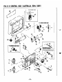
FIG. 3- 8 CONTROL BOX (AUSTRALIA, 50Hz- 24OV)
I
For Oil sensor type
1

FIG. 3- 8 CONTROL BOX (AUSTRALIA, !5Of=lz- 24OV)
Interchauseabilitv
Description
CONTROL BOX ASS’ Y
Includes
item 2 thru 27, 33 thru 46
and 46
CONTROL BOX ASS’ Y
For Electric starter type
Includes
items 2 thru 25.27 thru 30.
33 thru 43, 48 and 47
CONTROL BOX ASS’ Y
For Oil sensor type
Includes
items 2 thru 27. 33 thru
40 and 44 thru 47
81 385-40724-08
*l 385-40725-08
1 386-43086-08
CONTROL BOX ASS’ Y
For Electric starter type with Oil sensor
Includes item 2 thru 25 and 28 thru 47
CONTROL BOX
CONTROL BOX
For Electric starter type, Oil sensor type
For Electric starter type with Oil sensor
CONTROL PANEL A ASS’ Y
Includes items 3 thru 27
CONTROL PANEL A ASS’ Y
For Electric starter type
Includes itens 3 thru 25 and 28
CONTROL PANEL A ASS’ Y
For Oil sensor type
Includes items 3 thru 27
1 386-43096-08
*2
385-41749-08
*2
385-41750-08
*2 385-41749-08
I
82
1385-41751-08
CONTROL PANEL A ASS’ Y
For Electric starter type with Oil sensor
Includes items 3 thru 25 and 28 thru 32
21 385-43723-08 1 CONTROL PANEL A
I I
31 388-45652-08 1 NO-FUSE BREAKER (20A)
id I
51 004-35030-60 1 SCREW and WASHER ASS’Y
L
6 320-75112-08
AC VOLTMETER (3OOV)
1
7 353-45719-08
AC RECEPTACLE (25OV-15A1
2
10 004-35041-00
SCREW and WASHER ASS’ Y
4
13~~002~17040-00 1 NUT
15
320-59855-08
FUSE HOLDER (DC)
1
320-59860-08
FUSE (1 OA)
1
363-45701-08
TERMINAL BOLT (Color:RED)
1
363-45700-08
TERMINAL BOLT (Color:BLACKl
1
353-49901-08
WING NUT
1
356-49907-08
SCREW
1
353-49902-08
NUT
1
332-00050-08
SPRING WASHER
2
353-49903-08
WASHER
1
16
17
18
19
20
-
21
22
23
Ii
rhen ordering parts ;
Always give the keel, Specification and Serial Number of Generator.
-
38
-

FIG. 3- 8 CONTROL BOX t AUSTRALlA, 50Hz-
24OW
I
For Oil sensor type
For Ektric starter type
For Electric I--
tvmwith Oilmnsor
I
- 39 -

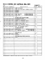
FIG. 3- 8 CONTROL BOX (AUSTRALIA. 50Hz-
24OV)
Interchangeability
Ref.
No.
Parts Number
Description
241 353-49035-08 1 LABEL(AC24OV)
1 1
25 363-49091-08
LABEL (DC BATTERY CHARGE ONLY) 1
26 389-47552-08 GROMMET 1
27 355-57509-08 GROMMET 1
28 066-00002-50 SWITCH For Electric starter
type
1
29 385-45517-08 FUSE HOLDER For Electric starter type 1
30 385-45518-08 FUSE (15A) For Electric starter
type
1
32 351-45302-08
LAMP, warning
For Electric starter type with Oil seasor
331 385-47541-08 1 CONDENSER(ZOfiF)
351 380-47531-08 1 CONDENSER BRACKET
381 004-35041-00 I SCREW and WASHER ASS’Y
I
31
371 389-59989-08 1 SCREW and WASHER ASS’Y
I 11
381 353-45804-08 I DIODE STACK ASS’Y
I
11
31
353-59949-08
I
SCREW and WASHER ASS’Y
I 11
228-71920-01
I REGULATOR, compl. For Electric starter type I
1 I
42 001-11062-50 BOLT and WASHER ASS’ Y
2
For Electric starter type
I I
431 385-47321-08 I CONNECTOR
For Electric starter tvpe
I
1
I
44 228-76001-01 OIL SENSOR, compl. For Oil seesor type 1
45 001-11063-50 BOLT and WASHER ASS’ Y 2
For Oil sensor type
48 353-49904-08
SCREW 8
471 385-57511-08 1 GROMMET
For Oil sensor type or Electric starter type
48 385-59227-08
LABEL
1
1
When ordering parts ; Always give the kdel, Specification and Serial hber of Generator.
-40-

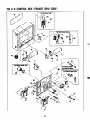
FIG. 3- 9 CONTROL BOX (FRANCE. 50X2-
22OV)
I
For Oil sensor type
I
LI
--

FIG. 3- 9 CONTROL BOX (FRANCE. ‘BOHz-
22OV)
_ _
f-
‘\
-----
--a--,
Ref.
No.
Parts Number
Description
1’ t)
+
Execution
*l 385-40965-08 CONTROL BOX ASS’ Y 1
Includes itews 2 thru 27, 33 thru 46 and 46
*l 385-40966-08 CONTROL BOX ASS’ Y
1
For Electric starter type
Includes iteas 2 thru 25,27 thru 30, 33 thru 43, 48 and 47
81 385-40928-08 CONTROL BOX ASS’ Y For Oil swnsor type 1
Includes itews 2 thru 27, 33 thru 40 and 44 thru 47
*l 385-40967-08 CONTROL BOX ASS’ Y 1
For Electric starter type with Oil sensor
Includes it.ews 2 thru 25 and 28 thru 47
1 386-43086-08 CONTROL BOX 1
1 386-43096-08 CONTROL BOX 1
For Electric starter type,,Oil sensor type
For Electric starter type with Oil sensor
82 385-41965-08 CONTROL PANEL A ASS’ Y 1
Includes iters 3 thru 27
*2 385-41966-08
CONTROL PANEL A ASS’ Y
1
For Electric starter type
Includes itews 3 thru 25, 27 and 28
*2 385-41929-08 CONTROL PANEL A ASS’ Y 1
For Oil sensor type
Includes itews 3 thru 27
*2 385-41967-08
CONTROL PANEL A ASS’ Y
1
For Electric starter type with Oil sensor
17 363-45701-08 TERMINAL BOLT (Color:RED) 1
18 363-45700-08 TERMINAL BOLT(Color:BLACK) 1
19 353-49901-08 WING NUT 1
20 356-49907-08 SCREW 1
21 353-49902-08 NUT 1
22 332-00050-08 SPRING WASHER 2
~&en ordering parts ; Always give the kdel, Specification and Serial Nuabar of Generator.
-
42
-

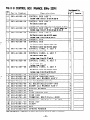
FIG. 3- 9 CONTROL BOX (FRANCE, 50Hz-
22OV)
r
For Electric starter type

FIG. 3 - 9 CONTROL BOX (FRANCE. 50Hz- 22OV)
--w-m-.
-a-* -,
Ref.
No.
Parts Number
Description
1’ ty
Execution
23 353-49903-08
WASHER
1
26 389-47552-08
GROMMET
1
27 355-57509-08
GROMMET
1
28 066-00002-50
SWITCH For Electric
starter type 1
29 385-45517-08
FUSE HOLDER For Electric
starter
type
1
30 385-45518-06
FUSE (15A) For Electric
starter type 1
32 351-45302-08
LAMP, warning
1
For Electric starter type with Oil sensor
For Oil sensor type or Electric starter
type
When ordering parts ; Always give the Nodel, Specification and Serial Number of Generator.

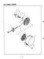
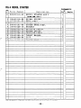
FIG. 4 RECOIL STARTER
-
45
-

FIG. 4 RECOIL STARTER
Ref.
No.
Parts Number
Description
*1 228-50110-00
RECOIL STARTER ASS’ Y
Intexdangdili ty
P’ ty
Executiw
1
f 21 106-50116-08
Includes iters 2 thru 11
SPIRAL SPRING
1
I
1 3 107-50121-08
4 228-50110-08
5 206-50101-08
6 106-50128-18
7
106-50132-08
8 106-50137-18
I
01 106-50144-18
10 106-50185-18
11 106-50186-08
12 011-00600-10
REEL compl.
1
STATER ROPE
1
STATER KNOB, camp 1.
1
RATCHET
2
FRICTION SPRING
1
RETURN SPRING
1
FRICTION PLATE
1
THRUST WASHER I 11
CLIP
FLANGE BOLT
I-
I
I
I
I I
when ordering parts ; Ahays give the Hodel, Specification and Serial Number of Generator.
- 46 -

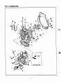
FIG. 5 CRANKCASE
For Oil sensor type
-
47
-

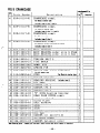
FIG. 5 CRANKCASE
lnter&aage&ility
Description
3’ ty
Execution
Ref.
I
Parts Number
No.
*l
228-10110-01
CRANKCASE, camp 1.
For Recoil starter type
1
Includes iteas 2 thru 7 aad 51
81 228-10112-01
CRANKCASE, camp 1. 1
For Electric starter type
Includes iteas 2 thru 7. 8 and 51
CRANKCASE, compl.
I ‘I
For Oil seasor type
I I
Includes itews 2 thru 8
CRANKCASE,
camp
1. 1
For Electric starter type with Oil sensor
I I
Includes iteas 2 thru 0
MAIN BEARING 1
2 228-15802-03
2 228-15803-03
MAIN BEARING, under size 0. 25mm 1
MAIN BEARING, under size 0. 5mm 1
TENSION BOLT 1 2
I
3) 228-18001-11
TENSION BOLT 2
PIPE KNOCK
1
DOWEL PIN
4
SPRING PIN
2
SWITCH ASS’ Y, oil pressure
1
For Oil sensor type
STUD
For Electric starter type 2
THRUST BEARING 1
L
811 I228-11501-11
BEARING HOUSING Includes itea 12
I
E
12) 044-04000-20
OIL SEAL
131 228-l 5004-03 GASKET. t-0. 1
I 11
13) 228-l 5005-03
GASKET, t-0. 2
I 11
131 228-15006-03
GASKET, t=O. 3
I 11
141 228-15014-03
‘0”
RING. bearing housing
I 11
/
*15
228-11406-01
GEAR CASE COVER, compl.
Includes i teas 16 thru 19
1
I I
161 04 l-05000-1 1
BLIND PLATE
1
BALL BEARING
1
STUD
3
F
STUD
E
201 228-15007-03
GASKET, case cover (t-0. 5)
I 11
211 228-11601-03
OIL PAN I 11
221 228-l 5008-03
23) 228-26001-01
241 228-25001-03
GASKET, oil pan (t-1. 2)
BALANCER COVER
GASKET, balancer cover
give the kdel, Specification give the kdel, Specification and Serial Number of Generator.
and Serial Number
-
of Generator.
when ordering
parts ; Always
-48-

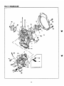
FIG. 5 CRANKCASE
For Oil smsor tvw
- 49 -

_
.
_-
-.
..___
-
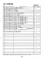
28 021-32000-10
GASKET
1
30 009-02120-00
FILLER
1
I
-
31
003-70120-00
GASKET, aluminum
1
32
228-64301-00
OIL FILTER ASS’Y
1
33 024-03000-10
‘0” RING
1
34 228-63601-01
OIL GAUGE. compl.
1
I
-
35 001-13088-50
BOLT and WASHER
ASS’
Y
4
38 001-13086-50
BOLT and WASHER
ASS’
Y 3
37 001-13082-00
BOLT and WASHER
ASS’
Y
6
-r
38
001-13084-00
BOLT and WASHER
ASS’
Y 2
39 001-13085-50
BOLT and WASHER
ASS’
Y 2
42 980-05060-10
BOLT and WASHER
ASS’
Y 13
43 014-90600-70
ADJUSTING SCREW
1
44 002-18060-00
NUT
2
I
I
451 041-12200-10 1 BLIND PLUG
I
I 1
I I
481 228-73147-01 1 WIRE 11, compl.
I
I 1
,
491 150-75201-03 1 CLAMP
I
For Oil sensor type I 1
50 001-10061-00
BOLT and WASHER ASS’ Y
1
For Oil sensor type
FIG. 5 CRANKCASE
Description
1511 212-15008-13 1 BLIND PLUG
I&en ordering prts : Always give the Hodel, Specification and Serial Nuaber of Generator.

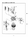
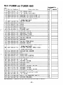
FIG. 6 CYLINDER and CYLINDER HEAD
16
5
3
13,
I
I 3’
32
-51-

FIG. 6 CYLINDER and CYLINDER HEAD
lnt*rchanaprhi 1 i tw
I . . -* -m--r* a a “,
Ref.
No.
Parts Number
Description
R’ ty
Execution
1 228-12401-12
CYLINDER UNIT
1
2 228-15011-03 ‘0” RING, cylinder 1
3 228-15012-13 SPACER, cylinder (t-0. 1) 1
3 228-15013-13 SPACER, cylinder (t-0. 2) 1
=4 228-13110-01 CYLINDER HEAD, comp.1. 1
Includes i teas 5 thru 8
5 228-14202-03
VALVE GUIDE
2
ker cover
When ordering parts : Always give the Hodel, Specification and Serial Number of Generator.
-
52
-

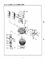
FIG 6 CYLINDER
and CYLINDER HEAD
. .-. - -. --.- ----
_..._ -
h
‘\
\ I
i
I
39
37
-
53
-

FtG. 6 CYLINDER and CYLINDER HEAD
Interchangeability
002-18060-00 1 NUT
1 4
When ordering parts : Always give tbe Hodel. Specification and Serial Wurber of Generator.

FIG. 7 CRANKSHAFT and PISTON
-
55
-

.
.
_,-
.
c
c
FIG. 7 CRANKSHAFT and PISTON
Interc@geability
Ref.
No.
Parts Number
Description
Y t
Execution
1 228-23401-23 PISTON, S. T. D 1
1 228-23402-23 PISTON, over size 0. 25mm 1
1 228-23403-23 PISTON, over size 0. 5mm 1
8 228-23501-07 PISTON RING SET, S. T. D 1
t-
Includes itees 2 thru 4
* 228-23502-07 PISTON RING SET, over size 0.25 88 1
I
1
I I
I--
Includes itess 2 thru 4
* I
228-23503-07 I PISTON RING SET,over size 0.5 88 I Includes iteus 2 thru 4 I 1
51 228-23301-03 1 PISTON PIN I II
I
61 056-52100-10 1 CLIP
I 21
I
‘71 228-20101- 11 1 CRANKSHAFT, compl.
Includes im 8 and 9 1 1 I
81 060-04000-30 1 BALL BEARING
I 1t
*lO 228-22501-00
I I
CONNECTING ROD ASS’ Y
1
Includes itees 11 and 12 I I
12 228-23001-03 CONNECTING ROD BOLT 2
13 228-22801-13 LARGE END BEARING, S. T. D 2
13 228-22802-13 LARGE END BEARING, undersize0.25n 2
1
131 228-22803-13 I LARGE END BEARING, undersizeO.Sn 1 2
I
141 228-22420-03 1 FLYWHEEL
For Recoii starter type 1 1
*14
228-22421-01
FLYWHEEL, compl. For Electric starter type 1
Includes i tees 15 thou 17
I I
F
l5-1 228-71001-03 1 RING GEAR
I
For Electric starter type 1~ 1 I
16 228-25003-03 PIPE KNOCK For Electric starter type 4
17 004-L 1082-50 SCREW For Electric starter
I
type 4
t
I
181 005-30072-01 1 KEY
1 1
181 017-32600-10 1 LOCK NUT
I 11
t
201 020-52600-12 t LOCK WASHER I 11
21 228-24402-13 DRIVING SHAFT 1
22 003-20100-00 SPRING WASHER 4
23 001-67103-00 BOLT 4
24 228-17821-03 ADAPTER, generator 1
25 001-13082-50 BOLT and WASHER ASS’ Y 4
E
I
1
I
I I I
I
Uhen ordering parts ; Always give the Hodel, Specification and Serial Number of Generator.
- 56 -

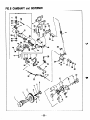
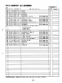
FIG.8 CAMSHAFT and GOVERNOR
For Oil sensor type
1

FIG. 8 CAMSHAFT and
GOVERNOR
c
.
c
No.
Parts Number
Description
*1 228-31604-00
CAMSHAFT ASS* Y
1
I I
Includea iteas 2, 3 and 4 thru 6
I I
81 228-31604-01
CAMSHAFT, camp
1. Includes i teas 4 thru 6 1
82 228-33222-01
CAMSHAFT
GEAR, c
omp 1. Include8 item 8 1
3 005-32042-01 WOODRUFF KEY I
25) 228-42310-02 1 GOVERNOR LEVER 2 UNIT
261 003-10100-00 1 WASHER
I 11
271 003-13080-00 I CLIP
281 004-35051-20 I SCREW and WASHER ASS’Y
291 002-18060-00 1 NUT
301 001-13062-00 1 BOLT and WASHER ASS’Y
I 21
311 228-45001-33 1 START SPRING
I 11
32) 228-42501-23 1 GOVERNOR SPRING
I 11
33 228-42901-01 CONTROL LINK, compl. 1
34 228-43311-11 SPEED CONTROL 1, compl. 1
35 006-26100-50 ‘0” RING 1
S 023-00800-10 SPACER
1
37 021-70800-10
FRICTION WASHER
1
38 003-10080-00 WASHER 2
3 002-28080-00 NUT 2
40 056-50400-10 CLIP 1
41 228-35006-03 GASKET, muffler 1
42 228-40151-01 CONTROL PANEL, compl. 1
I
I
431 228-92109-03 1 LABEL,operation
1 1
228-92111-03 LABEL, operation For FRANCE 1
228-43361-01 SPEED CONTROL 2, compl. 1
228-45301-01 LINK PIVOT 1
227-43601-03 KNOB 1
228-45005-01 CONTROL SPRING 1
L-
E
E
E
I=
I=
E
Imu ordering parts ; Always give the kdel, Specification and Serial Number of Generator.
-
58
-

FIG. 8 CAMSHAFT and GOVERNOR
1
For Oil sensor type
5
4
\\
- 59 -

c
FIG. 8 CAMSHAFT and GOVEWUOR
Interchangeability
escription
48 Oil-50500-IO BOLT 2
49 004-31063-50 SCREW 1
50 020-00800-90 WASHER 1
511 228-45021-01 1
BRACKET, pivot
For Oil sensor type 1
52 228-45020-01 ROD For Oil sensor type 1
53 005-10301-50
COTTER PIN
For Oil sensor type I
54 228-75901-11 BRACKET BASE For Oil sensor tvDe 1
55 228-75801-11 BRACKET, solenoid For Oil sensor type 1
58 024-10300-10 GROMMET For Oil sensor type 1
*57 228-75701-00 SOLENOID COVER ASS’ Y 1
I I I
For Oil sensor type
I I
I I I
Includes im 87
I I
1581 011-00600-60 I FLANGE BOLT ForOilsensortvDe
I 41
i 601 056-30000-10 I WIRE BAND
581 228-75004-10 1 SOLENOID ASS’ Y
I I
611 228-46110-11 1 LINK, compl.
62 228-45301-01 LINK PIVOT
63 021-70800-10 FRICTION WASHER
64 111-45501-03 NYLON BUSH
85 003-10080-00 WASHER
88 002-18060-00 NUT
67 228-75005-03 SPONGE
For Oil sensor type
I 1 I
For Oil sensor type 1
__
For Oil sensor type 1 1
For Oil sensor type 1
For Oil sensor type 1
For Oil sensor type 2
For Oil sensor type 1
I
For Oil . sensor tye. 1
For Oil sensor type -’ 1
l&en or&ring parts ; Always give the Ho&l, Specification and Serial Nuaber of Generator.
-60-

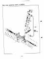
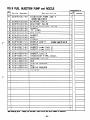
FIG. 9 FUEL INJECTION PUMP and NOZZLE
1
-33
. ;.
e!iL
._
:.
40
/
-61
-

-.
c
c
Interchangeability
Ref.
No.
Parts Number
Description
a’ ty
Execution
*lI 228-63101-00 1 INJECTION PUMP ASS’Y
I 11
Includes i tees 2 thru 21
3 228-63102-08
PLUNGER ASS’ Y
1
4 228-63103-08 DELIVERY VALVE 1
5 222-63104-08 SPRING,delivery valve 1
6 222-63105-08 GASKET 1
8 228-63105-08
I
I
'0" RING 1
181 228-63112-08 1 EYE BOLT
I -
I 1
19 222-63116-08 GASKET 2
20 228-63113-08 BOLT 1
211 211-63212-08 1 GASKET
I
11
1221 228-63201-10 1 NOZZLE ASS’Y
Includes itezs 23 thru 30 1 1
301 228-63211-08 1 NOZZLE
I 11
311 228-65017-03 I GASKET, pump (t-0. 1)
311 228-65022-03 1 GASKET, pump (t-0. 21
311 228-65018-03 1 GASKET, pump (t-0. 3)
1 1
~1
228-65004-03 1 GASKET.nozzle
I
11
331 228-63301-01 1 INJECTION PIPE,compl.
1 1
341 228-66001-01
I
BRACKET.nozzle
I II
351 002-18080-00 1 NUT
I 31
381 003-20080-00 I SPRING WASHER
I 31
371 002-18060-00 I NUT
I
21
38 003-20060-00 SPRING WASHER 2
40 222-65006-03 GROMMET 1
FIG. 9 FUEL INJECTION PUMP and NOZZLE
when ordering parts ; Aleays give the Model, Specification and Serial Nueber of Generator.
- 62 -

FIG. 10 FUEL FILTER
23
u
25
-P+
\
P
-
63
-

r
.
c
I
1 Inclndes itees 1 thru 11
I I
81 228-62109-08 1 ‘0” RING
I 11
91 228-62110-08 1 ELEMENT
121 001-13086-50 1 BOLT and WASHER
I 11
8141 228-62629-01 1 FUEL PIPE 29. compl.
I ‘I
I
I
Includes items 15 thrn 17 and 21
I’I
I
I
15 228-65007-03
BANJO 3
1
18 085-10400-00
RUBBER PIPE (4. 5#X9+X270mm)
1
17 085-10400-00
RUBBER PIPE (4. 5#XB#Xl70mm)
1
*18 228-62611-01
FUEL PIPE 11, compl.
1
Includes items 19, 30
and 22
19 052-10500-12
BANJO
1
20 085-10600-00
RUBBER PIPE
(69X12#X250mm)
1
21 056-10800-10
HOSE CLAMP
4
22 056-11100-20
HOSE CLAMP
4
23 085-10600-00
RUBBER PIPE (6#X12+X150mm)
1
24 228-67010-01
CLAMP, camp 1.
1
25 228-65012-03
PURSE LOCK 2
1
28 053-00800-10
BANJO BOLT
1
29 003-00080-00
GASKET, a 1 umi num
2
FIG. 10 FUEL
FllTER
i l&rchangeabili ty
f
1
Ref.
Parts Number
No.
Description
!Y ty
Execution
81
228-62106-00
FUEL FILTER ASS’ Y
1
I I
31
056-60001-70
CLAMP
1
I
I
I I
Uhen ox&ring parts ; Always give the kdel, Specification and Serial Number of Generator.
-64-

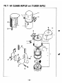
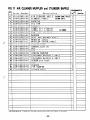
FIG. 11 AIR CLEANER, MUFFLER and CYLINDER BAFFLE
8
29
@d
-
65
-

FIG. 11 AIR CLEANER, MUFFLER and CYLINDER SAFFLE Interchanleabilfty
Ref.
Parts Number
No.
Description
P’ ty
Executicm
1.11 231-32601-00 1 AIR CLEANER ASS’ Y lncludesiteas2thru8~ 11
*3 228-32600-08 ELEMENT, compl. Includes itee 4 1
4 228-32720-08 PACKING 1
5 228-32710-08 OIL PAN 1
I I I
61 228-32601-18 [ ELEMENT 1 1
I
1 71 228-92302-03 1 LABEL,air cleaner
I 11
7 228-92303-03 LABEL, air cleaner For FRANCE 1
8 228-35009-03 CAP, air cleaner 1
1 -91 020-00600-20 1 WASHER
I 11
101 980-05060-10 1 BOLT and WASHER ASS’Y
[ 1
211 002-17050-00 NUT 1 1
271 228-55005-03 RUBBER 1 2
28 228-55004-03 FIN DAMPER 2
29 011-00600-20 FLANGE BOLT 2
,
When ordering parts
: Always give the Raiel, Specification and Serial Nurher of Generator.
-
66
-

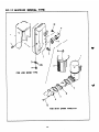
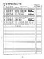
FIG-
12 MUFFLER (SPECIAL
TYPE)
FOR LOW NOISE TYPE
12
FOR WITH SPARK ARRESTER
-
67
-

1 41 228-37001-01 I TAIL PIPE, compl.
I 61 228-37301-01 1 SPARK ARRESTER.comnl.
I 1
1 228-30302-01
MUFFLER,
compl.
For Spark arrester
1
2 228-34260-01 MUFFLER COVER, camp 1. For Lw noise 1
2 228-34201-11
MUFFLER
COVER,
camp
1. For Spark arrester
1
I
31 228-35019-01 1 MUFFLER BRACKET
For La noise
1 1
For b noise r 1
41 228-37010-01 1 TAIL PIPE,compl.
For Spark arrester 1
51 228-37201-11 I BAND, compl.
For Lorr noise
1 1
71 228-35017-03 1 GASKET,tail pipe
For Spark arrester1 2
For Lar noise
1 61
91 001-13081-60 I BOLT and WASHER ASS’Y
For LRI noise 1
10 001-13082-00 BOLT and WASHER ASS’ Y For Lcw noise 1
11 001-13062-50 BOLT and WASHER ASS’ Y For lar noise 1
For
Spark
arrester
1 81 011-00600-10 1 FLANGE BOLT
1 81 011-00600-10 1 FLANGE BOLT For Spark arrester I- 4 I
1121 001-13061-60 1 BOLT and WASHER ASS’Y
I 21
FIG. 12 MUFFLER (SPECIAL TYPE)
escrlption
t
I
I
I -
1
I I I I I
When orderiug parts ; Always give the lbiel, Specification aud Serial Nusber of &aerator.
-
68
-

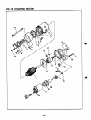
FIG. 13 STARTING MOTOR
- 69 -

r
.
c
I
I
Includes i teas 1 thru ~6. 29 and 30
I I
1 210-70532-08 ARMATURE ASS’ Y 1
2 210-70533-08 THRUST WASHER KIT 1
3 210-70534-08 PINION STOPPER SET
1
1
*4
I210-70535-08 1 FIELD COIL ASS’Y
Includes iteas 5 and 6 1
5 210-70508-08 POLE CORE SET SCREW
4
6 210-70539-08 BRUSH (+)
2
*7 210-70538-08 BRUSH HOLDER ASS’ Y
1
Includes itens 8 and 9
8 210-70540-08
BRUSH (-1
2
I
I
-
91 210-70541-08 1 BRUSH SPRING
I 4
I
I
ill 210-70542-08 1 REAR COVER METAL
I
I
1
12 210-70543-08 CENTER PLATE 1
13 210-70544-08 PINION ASS’ Y 1
*I4 I210-70545-08 1 GEAR CASE ASS’Y
Includes im 15
-L-l
151 210-70547-08 1 GEAR CASE METAL
I
1 1
161 210-70546-08 1 SHIFT LEVER KIT
1
17) 210-70548-08 1 MAGNETIC SWITCH ASS’Y
I 11
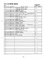
FIG. 13 STARTING MOTOR
Ref.
No.
Parts Number
Description
*l
210-70502-10
STARTING MOTOR ASS’ Y
*18 210-70550-18 DUST COVER KIT
lnclndes iters 19 thrn 21, 25 and 26
221 210-70549-08 1 THROUGH BOLT
I 21
271 093-20080-00 1 SPRING WASHER
I 21
281 002-18080-00 1 NUT
I 21
341 210-70551-08
I
BLIND COVER
I 11
Uhen ordering parts ; Always give the Hcdel, 6pecification and Serial Nuaber of 6enerator.
- 70 -

FIG. 14 ACCESSORIES
6
-71-

FIG. 14 ACCESSORIES
Part8 Number
1
I
I
I I
When ordering parts ;
Always
give the Hakl, Specification and Serial Number of Generator.
- 72 -

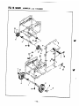
FIG. 15 WHEEL, HANDLE and HANGER

6
I-
7
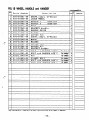
FIG. 15 WHEEL, HANDLE and HANGER
Ref.
No.
Parts Number
Description
1 385-56561-08
SHAFT.
comn
1. (2-whee
1)
Interch~~iiiy
1’ ty
Execution
1
1 16
_
450-00009-90
LARGE
WHEEL
2
385-56562-08
HANDLE
1
Includes itea
5
1
385-56563-08
HANDLE
2
Includes item
5
1
385-56517-08
CLIP
2
380-56548-08
BRACKET, handle
4
385-56564-08
HANDLE GUIDE
1
I
385-54387-08 1 WASHER
I -
I 2
I
385-54388-08 1 COTTER PIN
I -
I 2
385-54457-08
SHAFT, compl. (4-wheel) 1
385-54389-08
WHEEL
4
I
385-54390-08 1 WASHER
I -
I 4
I
385-54391-08 1 COTTER PIN
I -
I 4
I
385-54394-08 1 HANGER KIT
I -
I 1
385-54395-08
BRACKET, hanger
2
001-14081-60
BOLT and WASHER ASS’ Y
For 2-rheel 4
001-14061-60 1 BOLT and WASHER ASS’Y
I
For 4-ubeel 1 8
002-17080-00 1 NUT
I
For i-wheal 1 8
011-00600-30 1 FLANGE BOLT
I
For 2+eal 1 2
001-14082-00 1 BOLT and WASHER ASS’Y For kbeel 1 4
001-14082-00 1 BOLT and WASHER ASS’Y For HMCER 1 4
when orderiug parts ; Alrays give the Hodel, Specification
and
Serial Nuebar of Generator.

.
I

c
c

@FUJI HEAVY INDUSTRIES LTD.
-
INDUSTRIAL PRODUCTS DIV.
Subaru Bldg.
l-7-2, Nishi-Shinjuku, Shinjuku-ku, Tokyo 160, Japan
PHONE ; (Tokyo 3) 3347-2420
FACSIMILE ; (Tokyo 3) 3347-2418
PRINTED IN JAPAN
JUNE 1988
-
 1
1
-
 2
2
-
 3
3
-
 4
4
-
 5
5
-
 6
6
-
 7
7
-
 8
8
-
 9
9
-
 10
10
-
 11
11
-
 12
12
-
 13
13
-
 14
14
-
 15
15
-
 16
16
-
 17
17
-
 18
18
-
 19
19
-
 20
20
-
 21
21
-
 22
22
-
 23
23
-
 24
24
-
 25
25
-
 26
26
-
 27
27
-
 28
28
-
 29
29
-
 30
30
-
 31
31
-
 32
32
-
 33
33
-
 34
34
-
 35
35
-
 36
36
-
 37
37
-
 38
38
-
 39
39
-
 40
40
-
 41
41
-
 42
42
-
 43
43
-
 44
44
-
 45
45
-
 46
46
-
 47
47
-
 48
48
-
 49
49
-
 50
50
-
 51
51
-
 52
52
-
 53
53
-
 54
54
-
 55
55
-
 56
56
-
 57
57
-
 58
58
-
 59
59
-
 60
60
-
 61
61
-
 62
62
-
 63
63
-
 64
64
-
 65
65
-
 66
66
-
 67
67
-
 68
68
-
 69
69
-
 70
70
-
 71
71
-
 72
72
-
 73
73
-
 74
74
-
 75
75
-
 76
76
-
 77
77
-
 78
78
-
 79
79
-
 80
80


Subaru Robin Power Products RGD5000 Manual de usuario
- Tipo
- Manual de usuario
- Este manual también es adecuado para
Otros documentos
-
Hobart 5359D Operation and Maintenance Manual
-
Craftsman 917.377331 El manual del propietario
-
Miller KE582332 El manual del propietario
-
Powermatic DDS225 Drum Sander, 5HP 1PH 230V Manual de usuario
-
-
-
Yamaha SPX1000 El manual del propietario
-
Simplicity 580.328301 El manual del propietario
-
-
Reelcraft A5800 OMP Operating Instructions Manual