ZyXEL XGS3600-26F Guía de inicio rápido
- Categoría
- Conmutadores de red
- Tipo
- Guía de inicio rápido
Este manual también es adecuado para


Note: Go to www.zyxel.com to view this product’s
documentation and certifications.

ENGLISH
1
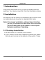
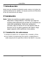
1 Introduction
This Quick Start Guide is for use with all ZyXEL Ethernet
switches. Your device may differ from the illustrations below.
2 Installation
All switches can be used as a standalone device while some
can alternatively be mounted on standard EIA racks.
Note: For proper ventilation, allow at least 4 inches
(10 cm) of clearance at the front and 3.4 inches
(8 cm) at the back of the switch. Leave space
between switches if stacking.
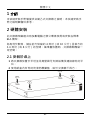
2.1 Desktop Installation
1 Set the switch on a smooth, level surface.
2 If your switch comes with unattached rubber feet, attach
them to each corner on the bottom of the switch. These
ENGLISH

2
ENGLISH
rubber feet help protect the switch from shock or vibration
and ensure space between devices when stacking.
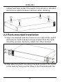
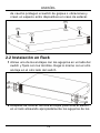
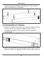
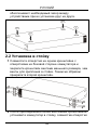
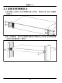
2.2 Rack-mounted Installation
1 Align one bracket with the holes on one side of the switch
and secure it with bracket screws smaller than the rack-
mounting screws. Similarly, attach the other bracket.
2 After attaching both mounting brackets, position the switch
in the rack by lining up the holes in the brackets with the

ENGLISH
3
appropriate holes on the rack. Secure the switch to the
rack with the rack-mounting screws.
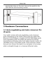
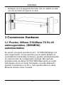
3 Hardware Connections
3.1 Auto-negotiating and Auto-crossover RJ-
45 ports
Your switch comes with auto-negotiating, auto-crossover
ports. Depending on the model, these ports are either fast
Ethernet (10/100 Mbps) or Gigabit (10/100/1000 Mbps) ports.
Auto-negotiating ports can detect the speed of incoming
transmissions and allow either half duplex transfer mode (10/
100 Mbps only) or full duplex mode. Auto-crossover means
that you can connect the switch to a computer or hub using
either a straight-through or a crossover Ethernet cable.

4
ENGLISH
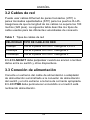
3.2 Network Cables
You can use unshielded twisted pair (UTP) or shielded
twisted-pair (STP) Ethernet cables for RJ-45 ports. Make sure
the cable length between connections does not exceed 100
meters (328 feet). The following table describes the types of
network cable used for different connection speeds.
Table 1 Network Cable Types
The LNK/ACT LED should flash when data is being sent
between your switch and a connected device.
3.3 Power Connection
Connect one end of the supplied power cable or power
adaptor to the power receptacle on the switch and the other
end to the appropriate power source. The PWR LED should
turn steady on if the switch is receiving power.
SPEED NETWORK CABLE TYPE
10Mbps 100 Ω 2-pair UTP/STP Category 3,4 or 5
100Mbps 100 Ω 2-pair UTP/STP Category 5
1000Mbps 100 Ω 4-pair UTP/STP Category 5

ENGLISH
5
3.4 Console Port (Managed Switches Only)
If your switch has a console port, you can use a terminal
emulator for local management. Connect the male 9-pin end
of a console cable to the console port of the switch. Connect
the female end to a serial port (COM1, COM2 or other COM
port) of your computer. Configure the computer with terminal
emulation software to the following parameters:
• VT100 terminal emulation
• 9600 bps
• No parity, 8 data bits, 1 stop bit
• No flow control
4 Troubleshooting
PROBLEM CORRECTIVE ACTION
None of the
LEDs are on
when the power
is connected.
Verify that the included power or cable
adaptor is connected to the switch's power
receptacle and appropriate power source.
If the error persists, you may have a
hardware problem and should contact your
vendor.
The LNK/ACT
LED does not
light up or flash
when a device
is connected.
Verify that the attached device(s) is turned on
and properly connected to your switch. Also
make sure the Ethernet cards are working on
the attached devices. Verify that the network
cable does not exceed 100 meters.

6
ENGLISH

DEUTSCH
7
1 Einleitung
Diese Kurzanleitung dient der Verwendung aller ZyXEL
Ethernet-Switche. Das Aussehen ihres Gerätes kann von den
unten gezeigten Abbildungen abweichen.
2 Installation
Note: Alle Switche können als Einzelgeräte verwendet
werden, wobei einige alternativ in 19 Zoll
Standardracks montiert werden können. Für eine
ausreichende Belüftung sollte vor dem Switch ein
Freiraum von mindestens 10 cm und hinter dem
Switch ein Freiraum von mindestens 8 cm gelassen
werden. Wenn Sie Switche übereinander
anordnen, lassen Sie einen Freiraum zwischen den
Geräten.
2.1 Tisch-Montage
1 Legen Sie den Switch auf eine glatte, ebene Unterlage.
2 Sollte Ihr Switch mit nicht montierten Gummifüßen
geliefert worden sein, bringen Sie diese an jeder Ecke der
Geräteunterseite an. Diese Gummifüße dienen dem
Schutz vor Stößen und Vibrationen und gewährleisten den
DEUTSCH

8
DEUTSCH
Freiraum zwischen den Geräten wenn diese übereinander
angeordnet werden.
2.2 Rack-Montage
1 Richten Sie die Bügel an den seitlich angeordneten
Löchern des Switch aus und sichern Sie diese mit den
dafür vorgesehenen Schrauben, die kleiner sind, als die
Schrauben die dafür verwendet werden, um das Gerät im
Rack zu befestigen. Gehen Sie analog dazu mit dem
anderen Bügel vor.

DEUTSCH
9
2 Nachdem beide Montagebügel angebracht sind,
positionieren Sie den Switch im Rack, indem Sie die
Löcher der Montage-bügel an den Montagelöchern des
Rack ausrichten. Sichern Sie den Switch mit den Rack-
Schrauben.
3 Hardware-Anschlüsse
3.1 10Base-T/100Base-TX RJ-45 Ports mit
Auto-Negotiating, Auto-Sensing- (MDI/
MDIX)-Funktion
Ihr Switch ist mit 10/100/1000 Mbit/s-RJ-45-Ports mit Auto-
Negotiating-Funktion ausgestattet, die die Geschwindigkeit
empfangener Datenpakete automatisch erkennen und
entsprechend einstellen. Sie ermöglichen Datentransferraten
von 10, 100, oder 1000 Mbit/s im Halb- oder Vollduplex-
Modus. Auto-Sensing bedeutet, dass Sie den Switch über ein
Straight-Through- oder Crossover-Netzwerkkabel mit einem
Computer oder einem Hub verbinden können.

10
DEUTSCH
3.2 Netzwerkkabel
Für RJ-45-Ports können Sie UTP (unshielded twisted-pair)-
oder STP (shielded twisted-pair)-Netzwerkkabel verwenden.
Achten Sie darauf, dass die Kabellänge zwischen den
Anschlüssen weniger als 100 Meter beträgt. Die folgende
Tabelle verdeutlicht die für die verschiedenen
Geschwindigkeiten verwendeten Netzwerkkabel-typen
Table 1 Netzwerkkabeltypen
Die LNK/ACT-LED sollte aufblinken, wenn Daten zwischen
Ihrem Switch und einem angeschlossenen Gerät versendet
werden.
3.3 Stromversorgung
Verbinden Sie das eine Ende des mitgelieferten Stromkabels
oder Netzteils mit dem dafür vorgesehenen Anschluss am
Switch. Verbinden Sie nun das andere Ende mit der
entsprechenden Stromquelle. Die PWR-LED sollte leuchten,
wenn der Switch mit Spannung versorgt wird.
GESCHWINDIGKEIT NETZWERKKABELTYP
10Mbps 100Ω 2-paarig UTP/STP Cat. 3,4 oder
5
100Mbps 100Ω 2-paarig UTP/STP Cat. 5
1000Mbps 100Ω 4-paarig UTP/STP Cat. 5

DEUTSCH
11
3.4 Konsolen-Port (nur managebare Switche)
Besitzt Ihr Switch einen Konsolen-Port, so können Sie zu
Konfigurationszwecken eine Terminal-Emulation verwenden.
Verbinden Sie den männlichen 9-Pin-Stecker eines
Konsolenkabels mit dem Konsolen-Port des Switch.
Verbinden Sie entsprechend den weiblichen Stecker mit
einem seriellen Port (COM1, COM2 oder anderer COM-Port)
Ihres Computers. Richten Sie die Terminal-Emulations-
Software auf Ihrem Rechner mit den folgenden Parametern
ein:
• VT100 Terminal-Emulation
• 9600 Bit/s
• Keine Parität (Parity), 8 Datenbits, 1 Stopp-Bit
• Kein "Flow Control" (Datenflusskontrolle)

12
DEUTSCH
4 Fehlersuche
PROBLEM KORREKTURMASSNAHME
Nach Anschluss
der
Stromversorgun
g leuchtet keine
der LEDs
Stellen Sie sicher, dass das mitgelieferte
Stromkabel oder Netzteil mit dem dafür
vorgesehenen Anschluss am Switch, bzw.
mit der entsprechenden Stromquelle
verbunden ist. Sollte das Problem
weiterhin bestehen, haben Sie
möglicherweise ein Hardwareproblem.
Wenden Sie sich in diesem Fall an Ihren
Händler.
Bei Anschluss
eines Gerätes
leuchtet bzw.
blinkt die LNK/
ACT-LED nicht
auf.
Stellen Sie sicher, dass die angeschlossenen
Geräte angeschaltet und ordnungsgemäß
mit Ihrem Switch verbunden sind. Achten Sie
auch darauf, dass die Netzwerkkarten der
angeschlossenen Geräte funktionieren.
Überprüfen Sie, ob die Länge des
Netzwerkkabels 100 Meter nicht
überschreitet.

ESPAÑOL
13
1 Introducción
Esta Guía de Instalación Rápida puede usarse con todos los
switches Ethernet de ZyXEL. Su equipo puede ser diferentes
al de las ilustraciones de abajo.
2 Instalación
Note: Todos los switches pueden usarse como
dispositivo independiente, mientras que algunos
modelos alternativamente pueden ser montados en
racks EIA estándares. Para una ventilación
correcta, deje al menos 10 cm de espacio libre al
frente 8 cm en la parte posterior del switch. Deje
algún espacio entre switches si los estaca.
2.1 Instalación de sobremesa
1 Coloque el switch en un espacio liso, nivelado y firme.
2 Si su switch incorpora pies de caucho, engánchelos a
cada esquina de la superficie inferior del switch. Los pies
ESPAÑOL

14
ESPAÑOL
de caucho protegen el switch de golpes o vibraciones y
crean un espacio entre dispositivos en caso de estacar.
2.2 Instalación en Rack
1 Alinee uno de los anclajes con los agujeros en un lado del
switch y fíjelo con los tornillos. Haga lo mismo con el otro
anclaje en el otro lado del switch.
2 Después de colocar los dos anclajes posicione el switch
en el rack alineando apropiadamente los agujeros de los

ESPAÑOL
15
anclajes con los agujeros del rack. Fije el switch al rack
con los tornillos de fijación al rack.
3 Conexiones Hardware
3.1 Puertos 10Base-T/100Base-TX RJ-45
autonegociables, (MDI/MDIX)
autodetectables
Su switch incorpora puertos RJ-45 10/100/1000 Mbps con
auto negociación, lo que permite que el switch detecte la
velocidad de transmisión entrante y ajustar automáticamente
sin intervención de configuración manual. Ello permite
transferencias de datos 10/100/1000 Mbps tanto en modo
half-duplex como en modo full-duplex. La auto detección
permite conectarse a un PC o hub usando tanto un cable
Ethernet directo como cruzado.

16
ESPAÑOL
3.2 Cables de red
Puede usar cables Ethernet de pares trenzados (UTP) o
pares trenzados apantallados (STP) para los puertos RJ-45.
Asegúrese de que la longitud de los cables no supera los 100
metros (328 pies). La siguiente tabla describe los tipos de
cable usados para las diferentes velocidades de conexión.
Table 1 Tipos de cables de red
El LED LNK/ACT debe parpadear cuando se envían o reciben
datos entre su switch y otros dispositivos.
3.3 Conexión de alimentación
Conecte un extremo del cable de alimentación o adaptador
de alimentación suministrado a la conexión de alimentación
del switch y el otro extremo a la toma de corriente apropiada.
El LED PWR debe permanecer encendido si el switch está
recibiendo alimentación.
VELOCIDAD TIPO DE CABLE DE RED
10Mbps 100 Ω 2-pares UTP/STP Categoría 3,4 o 5
100Mbps 100 Ω 2-pares UTP/STP Categoría 5
1000Mbps 100 Ω 4-pares UTP/STP Categoría 5

ESPAÑOL
17
3.4 Puerto consola (Solo switches
gestionables)
Si su switch tiene puerto consola puede usar un emulador de
terminal para gestión local. Conecte el extremo macho de 9
pines del cable consola al puerto consola del switch. Conecte
el extremo hembra al puerto serie (COM1, COM2 o otro
puerto COM) de su ordenador. Configure el puerto serie de
su ordenador con un software emulador de terminal con los
siguiente parámetros:
• emulador de terminal VT100
• 9600 bps
• Sin paridad, 8 bits de datos, 1 bit de parada
• Sin control de flujo

18
ESPAÑOL
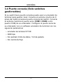
4 Solución de problemas
PROBLEMA ACCIÓN
Ningún LED
está activo y el
cable de
alimentación
está conectado.
Verifique que el cable de alimentación o
cable adaptador de alimentación está
conectado al conector de alimentación del
switch y a la toma de alimentación
adecuada. Si el error persiste seguramente
debe tener un problema de hardware,
contacte con su distribuidor.
El LED LNK/
ACT no se
enciende y no
parpadea
cuando el
switch está
encendido.
Verifique que los dispositivos conectados
estén encendidos y correctamente
conectados a su switch. También asegúrese
de que las tarjetas Ethernet de los
dispositivos conectados funcionan
correctamente. Verifique que los cables de
red no superan los 100 metros.

FRANÇAIS
19
1 Introduction
Ce Guide de Prise en Main est destiné à l'utilisation des
swithces Ethernet Dimension. Votre appareil peut différer des
illustrations ci-dessous.
2 Installation
Tous les switches peuvent être utilisés comme appareils
autonomes (sur un bureau) tandis que certains peuvent être
montés dans des châssis au standard EIA.
Note: Pour une bonne ventilation, laissez 10 cm d'espace
libre devant et 8 cm derrière le switch. Laissez de
l'espace entre les switches si vous les montez en
cascade.
2.1 Installation sur un bureau
1 Posez le switch sur une surface plate et droite.
2 Si votre switch est livré avec des pieds non attachés,
collez les sur chaque coin du socle du switch. Ces pieds
permettent de protéger le switch contre les vibrations de
FRANÇAIS

20
FRANÇAIS
chocs et assurent l'espace nécessaire si vous montez
plusieurs switches en cascade.
2.2 Installation en Châssis
1 Placez un angle sur les trous d'un côté du switch, et fixez
le avec les vis, qui sont plus petites que les vis de
montage en châssis. De la même manière, attachez
l'autre angle.
2 Après avoir attaché les deux angles, positionnez le switch
dans le châssis, en alignant les trous des angles avec les

FRANÇAIS
21
trous appropriés sur le châssis. Fixez le switch sur le
châssis avec les vis de montage en châssis.
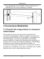
3 Connexions Matérielles
3.1 Ports RJ-45 à négociation et croisement
automatiques
Votre switch est livré avec des ports à négociation et
croisement automatiques. Selon le modèle, ces ports sont
des ports soit fast Ethernet (10/100 Mbps), soit Gigabit (10/
100/1000 Mbps). Les ports à négociation automatique
peuvent détecter la vitesse des transmissions entrantes, et
autoriser soit le mode de transfert half duplex (10/100 Mbps
seulement), soit le mode de transfert full duplex. Le
croisement automatique signifie que vous pouvez connecter
le switch à un ordinateur ou un hub, en utilisant soit un câble
Ethernet droit, soit un câble Ethernet croisé.

22
FRANÇAIS
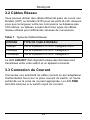
3.2 Câbles Réseau
Vous pouvez utiliser des câbles Ethernet paire de cuivre non
blindés (UTP) ou blindés (STP) pour les ports RJ-45. Assurez
vous que la longueur entre les connexions ne dépasse pas
100 mètres. Le tableau suivant décrit les types de câbles
réseau utilisés pour différentes vitesses de connexions.
Table 1 Types de Câbles Réseau
La LED LNK/ACT doit clignoter lorsque des données sont
transmises entre votre switch et un appareil connecté.
3.3 Connexion du Courant
Connectez une extrémité du câble courant ou de l'adaptateur
d'alimentation fourni sur la prise courant du switch, et l'autre
extrémité sur la prise de courant appropriée. La LED PWR
doit être allumée si le switch reçoit du courant.
VITESSE TYPE DE CABLE RESEAU
10Mbps 100 Ω 2-paires UTP/STP Categorie 3/4//5
100Mbps 100 Ω 2-paires UTP/STP Categorie 5
1000Mbps 100 Ω 4-paires UTP/STP Categorie 5

FRANÇAIS
23
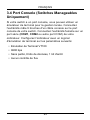
3.4 Port Console (Switches Manageables
Uniquement)
Si votre switch a un port console, vous pouvez utiliser un
émulateur de terminal pour la gestion locale. Connectez
l'extrémité mâle 9 broches d'un câble console sur le port
console de votre switch. Connectez l'extrémité femelle sur un
port série (COM1, COM2 ou autre port COM) de votre
ordinateur. Configurez l'ordinateur avec un logiciel
d'émulation de terminal sur les paramètres suivants:
• Emulation de Terminal VT100
• 9600 bps
• Sans parité, 8 bits de données, 1 bit d'arrêt
• Aucun contrôle de flux

24
FRANÇAIS
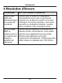
4 Résolution d'Erreurs
PROBLEME ACTION CORRECTIONNELLE
Aucune des
LEDs est
allumée lorsque
le courant est
connecté.
Vérifiez que le câble ou l'adaptateur
d'alimentation fourni est correctement
branché sur la prise du switch et la prise
électrique. Si l'erreur persiste, vous avez
peut-être un problème matériel, veuillez
alors contacter votre revendeur local.
La LED LNK/
ACT ne
s'allume pas ou
ne clignote pas
lorsqu'un
appareil est
connecté.
Vérifiez que les appareils connectés sont
allumés et bien connectés sur votre switch.
Assurez vous également que les cartes
Ethernet des appareils connectés
fonctionnent correctement. Vérifiez que votre
câble réseau ne dépasse pas 100 mètres.

ITALIANO
25
1 Introduzione
La guida utente è generalizzata per tutti gli switch Ethernet
ZyXEL. Il suo prodotto potrebbe essere differente rispetto alle
illustrazioni seguenti.
2 Installazione
Tutti gli switch possono essere usati come periferica
standalone ma possono anche essere montati in armadi
standard EIA.
Note: Per una ventilazione adeguata, lasciare almeno 10
cm di spazio di fronte e 8 cm sul retro dello switch.
Lasciare spazio fra gli switch se incolonnati.
2.1 Installazione Desktop
1 Posizionare lo switch su una superficie regolare e
livellata.
2 Se lo switch dovesse arrivare senza i piedini di gomma,
attaccarli in ogni angolo sul fondo dello switch. Questi
piedini aiutano a proteggere lo switch da shock o
ITALIANO

26
ITALIANO
vibrazioni e assicurano lo spazio fra le periferiche se
incolonnate.
2.2 Installazione in armadio Rack
1 Allineare una staffa con i buchi su un lato dello switch e
fissarla con viti da staffa più piccole di quelle per il
montaggio dell'armadio. Similarmete, attaccare le altre
staffe.
2 Dopo aver fissato entrambe le staffe, posizionare lo switch
nell'armadio allineando i fori delle staffe con quelli

ITALIANO
27
dell'armadio. Fissare lo switch all'armadio con le viti di
montaggio.
3 Collegamenti Hardware
3.1 Porte RJ-45 Auto-negozianti e Auto-
invertenti
Le porte dello switch sono auto-negozianti e auto-invertenti. A
seconda del modello, le porte possono essere di tipo Fast
Ethernet (10/100 Mbps) o Gigabit (10/100/1000 Mbps). Le
porte auto-negozianti, inoltre, riconoscono automaticamente
la velocità di trasmissione dati e supportano sia la modalità di
trasferimento dati half duplex (solo 10/100 Mbps) sia full
duplex. Auto-invertente significa che lo switch può essere
collegato ad un computer o a hub utilizzando sia un cavo
Ethernet "dritto" che uno "crossover" (incrociato).

28
ITALIANO
3.2 Cavi di rete
Si possono usare cavi a coppia incrociata non schermati
(UTP) o a coppia incrociata schermati (STP) per port RJ-45.
Assicurarsi che la lunghezza dei cavi fra i collegamenti non
superi i 100 metri. La seguente tabella descrive i tipi di cavi di
rete usati per le diverse velocità di collegamento.
Table 1 Tipi di cavo di rete
Il LED LNK/ACT dovrebbe illuminarsi quando i dati iniziano ad
essere trasmessi fra lo switch e le periferiche collegate.
3.3 Collegamenti di Alimentazione
Collegare un capo del cavo di alimentazione fornito o del
trasformatore ad una presa di corrente adatta. Il LED PWR
dovrebbe accendersi se lo switch viene alimentato.
SPEED NETWORK CABLE TYPE
10Mbps 100 Ω 2-pair UTP/STP Categoria 3,4 or 5
100Mbps 100 Ω
2-pair UTP/STP Categoria 5
1000Mbps 100 Ω4-pair UTP/STP Categoria 5

ITALIANO
29
3.4 Porta Console (Solo Switch
programmabili)
Se lo switch ha una porta console, si può usare un emulatore
di controllo locale. Collegare il capo maschio 9-pin del cavo
console alla porta console dello switch. Collegare il capo
femmina alla porta seriale (COM1, COM2 o altre porte COM)
del computer. Configurare il computer tramite un software di
emulazione di terminale con i seguenti parametri:
• Emulazione di terminale VT100
• 9600 bps
• Nessuna parità, 8 bit dati, 1 bit di stop
• Nessun controllo di flusso

30
ITALIANO
4 Analisi dei guasti
PROBLEMA AZIONE CORREYTIVA
Nessun LED si
accende
quando viene
collegata
l'alimentazione.
Verificare che l'adattatore fornito o il cavo
di alimentazione dello switch sia collegato
alla presa di corrente. Se il problema
persiste, potrebbe trattarsi di un guasto
hardware. Contatti il suo rivenditore.
Il LED LNK/
ACT non si
accende o
lampeggia
quando viene
collegata una
periferica.
Verificare che la periferica collegata sia
accesa e correttamente collegata allo switch.
Inoltre, assicurarsi che la scheda di rete sia
attiva con i dispositivi collegati. Verificare che
i cavi di rete non superino i 100 metri.

РУССКИЙ
31
1 Введение
Этот Ускоренный вводный курс предназначен для
использования со всеми коммутаторами Ethernet
производства ZyXEL. Ваше устройство может отличаться
от изображений на приведенных ниже иллюстрациях.
2 Простота
Все коммутаторы могут использоваться как
самостоятельные устройства, а некоторые модели
коммутаторов могут быть также установлены в стойку
стандарта EIA.
ПРИМЕЧАНИЕ: Для обеспечения необходимой
вентиляции необходимо оставить зазор как минимум 10
см спереди и 8 см сзади от коммутатора. Оставляйте
зазор между коммутаторами при их установке друг на
друга.
2.1 Установка на столе
1 Установите коммутатор на гладкую ровную
поверхность.
2 Если резиновые ножки, входящие в комплект поставки,
не присоединены, присоедините их по углам к нижней
части коммутатора. Эти резиновые ножки
предохраняют коммутатор от ударов и вибрации и
РУССКИЙ

32
РУССКИЙ
обеспечивают необходимый зазор между
устройствами при их установке друг на друга.
2.2 Установка в стойку
1 Совместите отверстия на одном кронштейне с
отверстиями на боковой стороне коммутатора и
закрепите кронштейн винтами меньшего размера, чем
винты для крепления в стойке. Таким же образом
прикрепите второй кронштейн.
2 После присоединения обоих монтажных кронштейнов
установите коммутатор в стойку, совместив отверстия

РУССКИЙ
33
в кронштейнах с соответствующими отверстиями в
стойке. Закрепите коммутатор в стойке с помощью
винтов для крепления в стойке.
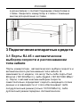
3 Подключение аппаратных средств
3.1 Порты RJ-45 с автоматическим
выбором скорости и распознаванием
типа кабеля
Порты коммутатора автоматического выбора скорости и
автоматического распознавания типа кабеля. В
зависимости от модели, это могут быть либо порты Fast
Ethernet (10/100 Мбит/с), либо Gigabit (10/100/1000 Мбит/
с). Порты с автоматическим выбором скорости
самостоятельно определяют скорость входящего потока
данных и в зависимости от этого обеспечивают либо
полудуплексный режим (только 10/100 Мбит/с), либо
дуплексный режим
передачи. Автоматическое

34
РУССКИЙ
распознавание типа кабеля означает, что коммутатор
можно подключить к компьютеру или концентратору,
используя как прямой, так и перекрестный кабель
Ethernet.
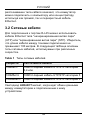
3.2 Сетевые кабели
Для подключения к портам RJ-45 можно использовать
кабели Ethernet типа "неэкранированная витая пара"
(UTP) или "экранированная витая пара" (STP). Убедитесь,
что длина кабеля между точками подключения не
превышает 100 метров. В следующей таблице описаны
типы сетевых кабелей, используемых при различных
скоростях.
Table 1 Типы сетевых кабелей
Светодиод LNK/ACT мигает, когда идет обмен данными
между коммутатором и подключенным
к нему
устройством.
Скорость Тип сетевого кабеля
10Мбит/с 100Ω 2-парный кабель UTP/STP категории
3,4 или
100Мбит/с 100Ω 2-парный кабель UTP/STP категории 5
1000Мбит/с 100Ω 4-парный кабель UTP/STP категории 5

РУССКИЙ
35
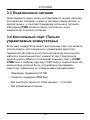
3.3 Подключение питания
Подсоедините один конец поставляемого шнура питания
или адаптер питания к розетке питания коммутатора, а
другой конец - к соответствующему источнику питания.
Светодиод PWR должен гореть постоянно, если
коммутатор получает питание.
3.4 Консольный порт (Только
управляемые коммутаторы)
Если ваш коммутатор имеет консольный порт, вы можете
использовать для локального управления эмулятор
терминала. Вставьте 9-контактный разъем консольного
кабеля в консольный порт коммутатора. Подключите
другой конец кабеля к последовательному порту (COM1,
COM2 или к любому другому COM порту) компьютера. На
компьютере должна быть установлена программа-
эмулятор терминала со следующими параметрами:
• Эмуляция
терминала VT100
• Скорость передачи 9600 бод
• без контроля четности, 8 бит данных, 1 стоп-бит
• без управления потоком

36
РУССКИЙ
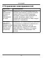
4 Устранение неисправностей
Проблема Рекомендации
При
включенном
питании ни
один из
светодиодов
не горит.
Убедитесь, что поставляемый адаптер
питания подсоединен к розетке питания
коммутатора и к соответствующему
источнику питания. Если проблема не
исчезла, возможно, имеет место
аппаратная неисправность. Вам следует
связаться с продавцом.
Светодиод
LNK/ACT не
загорается или
мигает, когда
подключено
устройство.
Убедитесь, что подключенное
устройство
(-а) включено и правильно подключено к
коммутатору. Убедитесь, что на
подключенных устройствах работают
карты Ethernet. Убедитесь, что длина
сетевого кабеля не превышает 100
метров.

繁體中文
37
1 介紹
本快速安裝手冊僅提供合勤乙太交換器之說明。本快速安裝手
冊之說明圖僅供參考。
2 硬體安裝
此交換器相當適合有多數電腦之辦公環境使用或安裝在標準
EIA 機架。
為有利於散熱,請在前方保留約 4 英吋 ( 或 10 公分 ) 且後方約
3.4 英吋 ( 或 8 公分 ) 的空間。當堆疊放置時,交換器間應留一
定空間。
2.1 安裝於桌上
1 將交換器放置於平坦並足夠堅固可支撐設備及連接線材的平
台。
2 使用紙盒內所附的防滑防震腳墊,貼於交換器下四方。
繁體中文

38
繁體中文
2.2 安裝於標準機架上
1 將耳翼上的錐孔和交換器的鎖孔對齊,再用內附 M3 平頭螺
絲鎖上。
2 鎖上耳翼後,確定交換器和機架的螺絲孔已對齊並用機架螺
絲將交換器鎖緊上機架。

繁體中文
39
3 硬體連接
3.1 自動偵測及自動交換的 RJ-45 埠
本交換器 RJ-45 埠均為自動偵測及自動交換埠。自動偵測的功
能讓交換器在不需要手動設定下,能針對所連接之傳輸速率自
動更換至相對應之速率。不論是在全雙工或半雙工下 ,它將依
你的乙太網路環境自動調整至 10Mbps、100Mbps 或
1000Mbps 資料傳輸速率 ( 高速乙太交換器不支援 10Mbps 資料
傳輸速率 )。自動交換的功能讓交換器在不需要變更乙太網路設
定下,自動選擇正向連接或反向連接,方便連接至個人電腦或
串接至另一部交換器。
3.2 網路線種類
請使用 UTP 或 STP 網路線來連接 RJ-45 埠。
請確定網路連接線不可超過 100 公尺 (328 英呎 )
以下的表格敘述了適用各種不同的連線速度的網路線。

40
繁體中文
表 1 網路線種類
當網路線和電源接上時,如有資料傳輸 LNK/ACT 指示燈會閃
示。
3.3 電源之連接
將電源轉接器一端接至電插座,另一端接至交換器之後背板。
此時,電源指示燈會正常顯示。
3.4 控制埠 ( 只提供給可設定交換器 )
如你的交換器有附控制埠,你可以透過終端機模擬程式控制你的交換器。
將控制埠接連線 9 孔公頭端接在交換器,接連線另一端接於個人電腦的
串列埠 (COM1, COM2 或其它 COM 埠 )。設定下列的連接參數於終端機
模擬程式 :
• VT100 終端 模擬
• 每秒傳輸位元 9600
• 無撿查同位,每份資料含 8 個資料位元,1 個停止位元
• 無流量控制
連線速度 網路線種類
10Mbps 100Ω 2-pair UTP/STP Category 3/4/5
100Mbps
100Ω 2-pair UTP/STP Category 5
1000Mbps
100Ω 4-pair UTP/STP Category 5

繁體中文
41
4 問題排除
Taiwanese BSMI (Bureau of Standards, Metrology and
Inspection) A Warning:
安全警告
為了您的安全,請先閱讀以下警告及指示 :
• 請勿將此產品接近水、火焰或放置在高溫的環境。
• 避免設備接觸
• 任何液體 - 切勿讓設備接觸水、雨水、高濕度、污水腐蝕性
的液體或其他水份。
問題 問題排除
當電源接上時所
有指示燈無顯
示。
請確定您已使用內附電源轉接器接至交換器
並開電源。
如持續無法開交換器請通知購買之廠商。
當網路線和電源
接上時 LNK/
ACT指示燈無顯
示。
請確定您已開交換器並使用網路線接上一台
電腦。
請確定此電腦的網路卡運作正常。
請確定網路連接線沒有超過 100 公尺 (328 英
呎)

42
繁體中文
• 灰塵及污物 - 切勿接觸灰塵、污物、沙土、食物或其他不合
適的材料。
• 切勿重摔或撞擊設備,並勿使用不正確的電源變壓器。
若接上不正確的電源變壓器會有爆炸的風險。
• 請勿隨意更換產品內的電池。
• 如果更換不正確之電池型式,會有爆炸的風險,請依製造商
說明書處理使用過之電池。
• 請將廢電池丟棄在適當的電器或電子設備回收處。
• 請勿將設備解體。
• 請勿阻礙設備的散熱孔,空氣對流不足將會造成設備損害。
• 請插在正確的電壓供給插座 ( 如 : 北美 / 台灣電壓 110V AC,歐
洲是 230V AC)。
• 假若電源變壓器或電源變壓器的纜線損壞,請從插座拔除,若您
還繼續插電使用,會有觸電死亡的風險。
• 請勿試圖修理電源變壓器或電源變壓器的纜線,若有毀損,請直
接聯絡您購買的店家,購買一個新的電源變壓器。
• 請勿將此設備安裝於室外,此設備僅適合放置於室內。請勿隨一
般垃圾丟棄。
-
 1
1
-
 2
2
-
 3
3
-
 4
4
-
 5
5
-
 6
6
-
 7
7
-
 8
8
-
 9
9
-
 10
10
-
 11
11
-
 12
12
-
 13
13
-
 14
14
-
 15
15
-
 16
16
-
 17
17
-
 18
18
-
 19
19
-
 20
20
-
 21
21
-
 22
22
-
 23
23
-
 24
24
-
 25
25
-
 26
26
-
 27
27
-
 28
28
-
 29
29
-
 30
30
-
 31
31
-
 32
32
-
 33
33
-
 34
34
-
 35
35
-
 36
36
-
 37
37
-
 38
38
-
 39
39
-
 40
40
-
 41
41
-
 42
42
-
 43
43
-
 44
44


ZyXEL XGS3600-26F Guía de inicio rápido
- Categoría
- Conmutadores de red
- Tipo
- Guía de inicio rápido
- Este manual también es adecuado para
en otros idiomas
- français: ZyXEL XGS3600-26F Guide de démarrage rapide
- italiano: ZyXEL XGS3600-26F Guida Rapida
- Deutsch: ZyXEL XGS3600-26F Schnellstartanleitung
Artículos relacionados
-
ZyXEL Communications ES-2024 Series Manual de usuario
-
-
ZyXEL Communications ES-124P Manual de usuario
-
 ZyXEL Communications ES-108A Manual de usuario
-
 ZyXEL Communications ES-105A/108A Manual de usuario
-
ZyXEL Communications Ethernet switch Manual de usuario


