Lucci Air 21052001 Instrucciones de operación
- Categoría
- Ventiladores domésticos
- Tipo
- Instrucciones de operación
Este manual también es adecuado para

V1. 0 p u b l i s h e d o n 0 1 . 2 0 1 7
LUCCI
CLIMATE
DC CEILING FAN
INSTALLATION
OPERATION
MAINTENANCE
WARRANTY INFORMATION
CAUTION
READ INSTRUCTIONS CAREFULLY FOR SAFE
INSTALLATION AND FAN OPERATION.

Climate Installation Instructions
1 | P a g e
CONGRATULATIONS ON YOUR PURCHASE
Congratulations on purchasing the latest in energy saving ceiling fans. This fan runs on DC (direct current)
power which gives it the benefit of being super energy efficient whilst still maintaining high volume air-
movement and silent operation.
Energy Saving - The DC motor is the latest technology in fan design. Its highly efficient motor saves up to
65% more energy than ceiling fans with traditional AC motors.
Silent operation – This DC fan motor is programmed with a stabilised current which efficiently reduces motor
noise.
Low operating temperature – The DC power is managed effectively which brings down the motor operating
temperature to less than 50℃. This results in a much cooler motor than a standard AC fan and increases the
longevity of the motor.
6 speed remote control - Regular AC ceiling fans usually come with only 3 speeds, this DC fan comes
complete with a 6 speed remote, which gives greater choice of comfort levels.
SAFETY PRECAUTIONS
Read and Save These Instructions
This product conforms to UL standard 507.
1. WARNING -To avoid possible electrical shock, before installing or servicing your fan, disconnect the
power by turning off the circuit breaker of the fuse box to the outlet box.
2. WARNING - To reduce the risk of fire, electric shock, or personal injury, mount to outlet box marked
“acceptable for fan support of 35 lbs (15.9 kg) or less” and use the mounting screws provided with the
outlet box and/or support directly from building structure. Most outlet boxes commonly used for the
support of luminaries may not be acceptable for fan support and may need to be replaced. Consult a
qualified electrician if in doubt.
3. WARNING - To reduce the risk of fire or electric shock, do not use this fan with any solid-state speed
control device.
4. WARNING - To reduce the risk of personal injury, do not bend the blade brackets when installing the
blade brackets balancing the blades, or cleaning the fan. Do not insert foreign objects in between rotating
fan blades.
5. CAUTIONS - All wiring must be in accordance with the National Electrical Code (ANSI/NFPA 70) and
local electrical codes. Electrical installation should be performed by a qualified licensed electrician.
6. To reduce the risk of injury to person, the fan must be mounted with a minimum of 7 feet clearance from
the bottom edge of the blades to the floor.
7. After marking electrical connections, spliced conductors should be turned upward and pushed carefully
up into the outlet box. The wires should be spread apart with the grounded conductor and the equipment-
grounding conductor on one side of the outlet box.
8. This equipment has been tested and found to comply with the limits for a Class B digital device, pursuant
to part 15 of the FCC rules. These limits are to provide reasonable protection against harmful interference
in a residential installation. This equipment generates, uses and can radiate radio frequency energy and
if not installed and used in accordance with the instructions may cause harmful interference to radio
communications.

Climate Installation Instructions
2 | P a g e
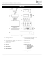
PARTS LIST
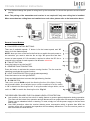
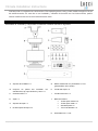
Unpack your fan and check the contents. You should have the following:
A.
Mounting bracket x 1
G.
Remote transmitter with holder x 1 set
(12V 23AE Battery included)
B.
Fan assembly with hanger cover, down rod,
canopy cover and canopy x 1
H.
Blade screw x 13
C.
Bottom cover x 1
I.
Motor screws x 9
D.
Blade x 4
J.
Mounting screw bag:
• Wood screw x 2
• Machine screw x 2
• Flat washer x 2
• Wire nut x 5
E.
Blade holder x 4
F.
Blade holder kit x 4
K.
Balancing kits x 1 set
Fig. 1

Climate Installation Instructions
3 | P a g e
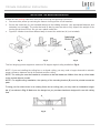
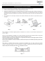
INSTALLING THE MOUNTING BRACKET
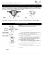
If there isn’t an existing outlet box, then install one using the following instructions:
• Disconnect the power by removing the fuses or turning off the circuit breakers.
• Secure the outlet box (A) (not included) directly to the building structure. Use appropriate fasteners and
materials (not included). The outlet box and its bracing must be able to fully support the weight of the
moving fan (at least 35 lbs). Do not use a plastic outlet box.
• Figures 2-4 below show three different ways to mount the outlet box (A) (not included).
This fan hanging system supports a maximum 20 degree angled ceiling installation. Fig. 4
NOTE: If you are installing the ceiling fan on a sloped ceiling, you may need a longer downrod to maintain
proper clearance between the tip of the blade and the ceiling.
NOTE: The ceiling fan must be installed in a location so that the blades are 300mm from the tip of the blade
to the nearest objects or walls.
NOTE: For angled ceiling installation, the opening of the mounting bracket (B) must be pointed toward the
peak.
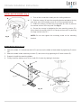
To hang your fan where there is an existing fixture but no ceiling joist, you may need an installation hanger
bar (C) as shown in Fig. 5. Make sure the hanger bar you purchase has been designed for use with ceiling
fans.
Fig. 2
Fig. 5
Fig. 3
Fig. 4

Climate Installation Instructions
4 | P a g e
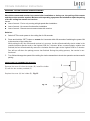
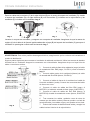
HANGING THE FAN
Pass the power supply wires (C) from the ceiling outlet box (B) through the center of the ceiling mounting
bracket (D). Install the ceiling mounting bracket (D) on the outlet box (B) with the mounting screws (F) provided
with the outlet box and washers (E) provided with fan. Fig. 6
Lift the fan assembly onto the mounting bracket. Ensure the registration slot (A) of the hanger ball is positioned
on the stopper (B) of the mounting bracket (C) to prevent the fan from rotating when in operation. Fig.7
ELECTRICAL WIRING DIAGRAM
WARNING: To avoid possible electrical shock, be sure you
have turned off the power at the main circuit panel.
Follow the steps below to connect the fan to your household
wiring. Use the wire connecting nuts supplied with your fan.
Secure the connectors with electrical tape. Make sure there are
no loose wire strands or connections.
1. Connect the household live supply wire (black) to EMI
filter input wire (black, AC IN L) as shown in Fig. 8.
2. Connect the household neutral supply wire (white) to the
EMI filter input wire (white, AC IN N).
3. Connect the household ground wire to the fan ground
wire (green). Connect the ground wire connectors together.
4. Connect the EMI filter output wire (black, TO MOTOR L)
to motor live input wire (black, TO MOTOR L).
5. Connect the EMI filter output wire (white, TO MOTOR N)
to motor neutral input wire (white, TO MOTOR N).
6. After connecting the wires, spread them apart so that the
green and white wires are on one side of the outlet box and the
black and blue wires are on the other side.
7. Turn the connecting nuts upward and push the wiring into
the outlet box.
Fig. 6
Fig. 7
Fig. 8

Climate Installation Instructions
5 | P a g e
FINISHING THE INSTALLATION
INSTALLING THE CANOPY (Fig. 9)
1. Tuck all the connections neatly into the ceiling outlet box.
2. Slide the canopy (A) up to the mounting bracket and place the key
hole slots over the mounting screw (D) on the mounting bracket.
3. Rotate the canopy (A) until the screw head (B) locks in place at
the narrow section of the key hole.See Fig. 9.
4. Secure the canopy by tightening the two mounting screws (D).
Now, attach the canopy cover (E) to canopy and secure it by pushing
the lugs into the holes (C).
NOTE: Do not over tighten the mounting screw on the mounting
bracket.
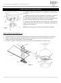
BLADE INSTALLATION (Fig.10)
1. Attach the blade (C) to blade bracket kit (D) and secure the blade to blade holder by tightening 3 screws
(B).
2. Attach the blade holder assembly to motor (F) and secure it by tightening the 2 motor screws (E).
3. Repeat to install the remaining blades.
4. Finally install the bottom cover (H) to shaft (G) of motor by rotating it clockwise.
Fig. 9
Fig. 10

Climate Installation Instructions
6 | P a g e
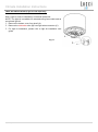
LIGHT KIT INSTALLATION (Light kit sold separately)
Note: Light kit must be installed by a licensed electrician.
NOTE: The light kit is available for selected ceiling fan models and as
an optional light kit.
1. Remove the bottom cover from shaft (A).
2. Remove the shrinkable tube (B) from light wires connector (C).
3. For light kit installation, please refer to light kit installation user
guide.
Fig. 11

Climate Installation Instructions
7 | P a g e
USING YOUR CEILING FAN
Pairing Transmitter and Receiver – when 2 or more DC ceiling fans are installed in one location
When two or more fans are located near each other, you may want to have the receiver/transmitter for each
fan set to a different code, so that the operation of one fan does not affect the operation of the other fan/s.
The DIP switches for the transmitter (remote hand piece) are located in the battery compartment of the
transmitter. Configuring the DIP switches will allow a unique transmission code assigned to each fan ceiling.
NOTE: Ensure that you have installed a single pole disconnection switch in the fixed wiring for each fan.
NOTE: Ensure power to the receiver is ON prior to pairing the transmitter with the receiver.
Transmitter / Receiver pairing for Ceiling fan 1:
Turn OFF the mains supply to the receivers of both ceiling fans 1 and 2.
Install the 12V DC battery in the compartment. Please make sure the polarity of the battery is correct.
Fig.12
Change the position of the DIP switches in the transmitter 1, so that it will be different to transmitter 2.
Turn on the power to receiver 1. Keep the power OFF to receiver 2. (Each ceiling fan must have its own
isolation switch, so that only the ceiling fan that needs to be paired with the transmitter will be ON).
Press and hold the “SET” button of transmitter 1 for 6 seconds within 60 seconds of switching the power
ON to the receiver of ceiling fan 1.
While pairing the DC fan remote and receiver is in process, the fan will automatically start to rotate in the
counterclockwise direction and on the highest RPM for 3 minutes. When counterclockwise rotation has
finished, the fan will automatically reverse to clockwise direction to the highest RPM for 3 minutes. Fan
will turn off when the pairing process has finished. During the pairing process, the remote is non-functional.
Turn ON and change the speed of the ceiling fan 1 by the transmitter 1 to check the operation and
successful pairing.
Transmitter / Receiver pairing for Ceiling fan 2:
Turn off the mains supply to the receivers of both ceiling fans 1 and 2.
Install the 12V DC battery in the compartment. Please make sure the polarity of the battery is correct.
Fig.12
Change the position of the DIP switches in the transmitter 2, so that it will be different to transmitter 1.
Turn on the power to receiver 2. Keep the power OFF to receiver 1. (Each ceiling fan must have its own
isolation switch, so that only the ceiling fan that needs to be paired with the transmitter will be ON).
Press and hold the “SET” button of transmitter 2 for 6 seconds within 60 seconds of switching the power
ON to the receiver of ceiling fan 2.
While pairing the DC fan remote and receiver is in process, the fan will automatically start to rotate in the
counterclockwise direction and on the highest RPM for 3 minutes. When counterclockwise rotation has
finished, the fan will automatically reverse to clockwise direction again to the highest RPM for 3 minutes.
Fan will turn off when the pairing process has finished. During the pairing process, the remote is non-
functional.

Climate Installation Instructions
8 | P a g e
Turn ON and change the speed of ceiling fan 2 by the transmitter 2 to check the operation and successful
pairing.
Note: The pairing of the transmitter and receiver is not required if only one ceiling fan is installed.
When more than two ceiling fans are installed near each other, please refer to the instruction above.
Remote Control Buttons
A - FAN SPEED CONTROL BUTTONS:
There are 6 available speeds. “I” button is for the lowest speed, and “VI”
button is for the fastest speed.
NOTE: when you turn on the fan for the first time or switch the main power to
the controller, you need to start the fan on high “VI” speed first and then
choose a lower speed. A 5-10 seconds is required to allow the DC fan to
respond to the remote for each speed or fan direction selections.
B - FAN OFF BUTTON:
Press the button to turn the fan OFF.
C - REVERSE FUNCTION BUTTON:
Press the button to activate the reverse running function. The fan must be
operating to activate the reverse function.
D - LIGHT CONTROL BUTTON: (Light kit sold separately)
Press the button to turn the light ON/OFF.
Press and hold the button to access the light dimming function.
E – D / ON SWITCH
This switch marked D/ON controls the dimming function of the lights. If using
non-dimmable bulbs, use a ballpoint pen or small screwdriver to set the switch
to “D” to disable the dimming function. If using dimmable halogen bulbs, set the
switch to “ON” to enable the dimming function. Fig. 14
THE RECEIVER PROVIDES THE FOLLOWING LEVEL OF PROTECTION:
Lock position: the receiver has a built in safety feature to protect against obstruction during operation.
The motor will be locked from operation and will disconnect from power after 30 seconds of interruption.
Please remove obstacles before re-starting. To reset, simply turn off the power supply to the fan motor
and re-start.
Over 80W protection: when the receiver detects power consumption which is greater than 80W, the
receiver power will be stopped and operation will immediately discontinue. Turn the receiver power on
after 5 seconds to restart the fan.
Fig. 12
Fig. 13
Fig. 14

Climate Installation Instructions
9 | P a g e
REPAIRING THE FAN RECEIVER & REMOTE PAIRING
Should the remote and receiver lose control after installation or during use, the pairing of the remote
and the receiver must be repaired. Below are the operating symptoms and method to repair the pairing
of the DC ceiling fan remote and receiver.
Issues:
Loss of control - Fan is only running at high speed after installation
Loss of control - No reverse function after installation
Loss of control - Remote cannot communicate with receiver
Solution:
A. Switch OFF the main power to the ceiling fan for 30 seconds.
B. Press and hold the “SET” button on remote for 6 seconds within 60 seconds of switching the power ON
to the receiver of the ceiling fan.
While pairing the DC fan remote and receiver is in process, the fan will automatically start to rotate in the
counterclockwise direction and on the highest RPM for 3 minutes. When counterclockwise rotation has
finished, the fan will automatically reverse to clockwise direction again to the highest RPM for 3 minutes.
Fan will turn off when the pairing process has finished. During the pairing process, the remote is non-
functional.
C. Turn ON and change the speed of the ceiling fan via the transmitter to check the operation and successful
pairing.
INSTALLING THE TRANSMITTER HOLDER
Remove the cover (A) from the holder (B). Install the holder
(B) with the two screws provided (C).
Replace the cover (A) into holder (B). Fig. 15
Fig. 15

Climate Installation Instructions
10 | P a g e
AFTER INSTALLATION
WOBBLE:
NOTE: ceiling fans tend to move during operation due to the fact that they are mounted on a rubber grommet.
If the fan was mounted rigidly to the ceiling it would cause excessive vibration. Movement of a few centimetres
is quite acceptable and DOES NOT suggest any problem.
TO REDUCE THE FAN WOBBLE: Please check that all screws which fix the mounting bracket and down rod
are secure.
BALANCING KIT: A balancing kit is provided to balance the ceiling fan on initial installation. Please refer to
the instruction on how to use the balancing kit. The balancing kit can be used to assist re-balancing should
the ceiling fan become un-balanced again. Store your balancing kit away after installation for future use if
required.
NOISE:
When it is quiet (especially at night) you may hear occasional small noises. Slight power fluctuations and
frequency signals superimposed in the electricity for off-peak hot water control, may cause a change in fan
motor noise. This is normal. Please allow a 24-hour “breaking-in” period, most noises associated with a new
fan disappear during this time. All electric motors are audible to some extent. Please note that this is not a
product fault, and as such is not covered under warranty.
CARE AND CLEANING:
Periodic cleaning of your ceiling fan is the only maintenance required. Use a soft brush or lint free cloth
to avoid scratching the paint finish. Please turn off electricity power when you do so.
Do not use water when cleaning your ceiling fan. It could damage the motor or the blades and create the
possibility of an electrical shock.
The motor has a permanently lubricated ball bearing so there is no need to oil.
NOTE: Always turn OFF the power at the mains switch before attempting to clean your fan.
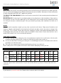
TECHNICAL INFORMATION
Fan Size
Speed
Volts
(V)
Amps
(A)
Watts
(W)
RPM
CFM
CFM/
W
N.W.
(lbs)
G.W.
(lbs)
C.F.
52”
CD52
Extra-High
120
0.25
32.88W
217
5705.56
173.53
12.1
14.52
1.37
Medium High
120
0.12
13.17W
150
4172.71
316.83
12.1
14.52
1.37
Low
120
0.05
2.78W
50
1266.19
455.46
12.1
14.52
1.37
These are approximate measurements. They do not include data for any lamps or fixtures attached to the
ceiling fan.
WARRANTY
2 year warranty covers the entire fan. Please refer to warranty card for the details.

Climate Installation Instructions
11 | P a g e
ENHORABUENA POR SU ADQUISICIÓN
Enhorabuena por la compra de lo último en ventiladores de techo de bajo consumo. Este ventilador utiliza
una corriente CC (corriente continua) para conseguir un gran ahorro de energía y proporcionar un elevado
volumen de desplazamiento de aire y una operación silenciosa.
Ahorro de energía - El motor CC incorpora la última tecnología en diseño de ventiladores. Su motor de alta
eficiencia ahorra hasta un 65% más de energía que los ventiladores de techo tradicionales con motores CA.
Operación silenciosa - El ventilador con motor CC está programado con una corriente estabilizada que
reduce el ruido del motor eficientemente.
Baja temperatura de funcionamiento – Gestión efectiva de la alimentación CC para rebajar la temperatura
de funcionamiento a menos de 50 ℃. Con esto se consigue un motor más frío que el de un ventilador CA
estándar y se aumenta la longevidad del motor.
Mando a distancia con 6 velocidades - Los ventiladores CA normales solo disponen de 3 velocidades. Este
ventilador CC incluye un mando a distancia con 6 velocidades que le proporciona más opciones en cuanto al
nivel de confort.
MEDIDAS DE SEGURIDAD
Lea y guarde estas instrucciones
Este producto cumple con la norma 507 de UL.
1. ADVERTENCIA - Para evitar posibles descargas eléctricas, corte la corriente que va a la caja eléctrica
desde el disyuntor o la caja de fusibles.
2. ADVERTENCIA - Para reducir el riesgo de incendio, descarga eléctrica o lesión, móntelo en una caja
eléctrica clasificada como «Apropiada para sostener ventiladores de 35 lb (15,9 kg) o menos», y utilice
los tornillos de montaje suministrados con la caja eléctrica y/o fíjelo directamente a la estructura del
edificio. La mayoría de las cajas eléctricas utilizadas comúnmente para el soporte de alumbrados puede
que no sean apropiadas para sostener el ventilador y deban ser reemplazadas. Consulte con un
electricista cualificado en caso de duda.
3. ADVERTENCIA - Para reducir el riesgo de incendio o electrocución, evite utilizar el ventilador con un
dispositivo semiconductor para el control de la velocidad.
4. ADVERTENCIA - Para reducir el riesgo de lesión, no doble los soportes de las aspas cuando los instale
en el que equilibran las aspas, o cuando limpie el ventilador. No inserte objetos entre las aspas en
rotación.
5. PRECAUCIÓN - Todo el cableado debe realizarse cumpliendo con el Código Eléctrico Nacional
(ANSI/NFPA 70) y los reglamentos de electricidad locales. La instalación eléctrica debería efectuarla un
electricista acreditado.
6. Para reducir el riesgo de lesiones a personas, el ventilador debe montarse dejando un espacio mínimo
de 2,13 m desde el lado inferior de las aspas hasta el suelo.
7. Después de realizar las conexiones eléctricas, los conductores empalmados deben reorientarse hacia
arriba y empujarse con cuidado hacia el interior de la caja eléctrica. Los cables deben quedar apartados,
con el conductor de tierra y el conductor de tierra del dispositivo a un lado de la caja eléctrica.
8. Tras someterlo a una serie de pruebas, se ha constatado que este aparato cumple los límites exigidos
para dispositivos digitales pertenecientes a la Categoría B, según lo establecido en la sección 15 de la
legislación de la FCC. Estos límites están diseñados para proporcionar una protección razonable contra

Climate Installation Instructions
12 | P a g e
interferencias en instalaciones residenciales. Este aparato genera, usa y puede irradiar energía en forma
de radiofrecuencia. En caso de no ser instalado y utilizado de acuerdo con las instrucciones, podría
causar interferencias en las comunicaciones de radio.
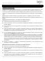
LISTA DE PIEZAS
Desembale el ventilador y compruebe el contenido. Debería incluirse lo siguiente:
A.
Soporte del ventilador x 1
G.
Mando a distancia con portamando x 1 set
(pila 23AE de 12V incluida)
B.
Conjunto de piezas del ventilador con
embellecedor, tija, tapa del florón y florón x 1
H.
Tornillo del aspa x 13
C.
Cubierta inferior x 1
I.
Tornillos del motor x 9
D.
Aspa x 4
J.
Bolsa de tornillos:
• Tornillo para madera x 2
• Tornillo para metal x 2
• Arandela plana x 2
• Tuerca de alambre x 5
E.
Soporte del aspa x 4
F.
Kit del soporte del aspa x 4
K.
Kit de balanceo x 1 set
Img. 1

Climate Installation Instructions
13 | P a g e
INSTALACIÓN DEL SOPORTE MURAL
Si no hay una caja eléctrica ya instalada, instale una siguiendo estas instrucciones:
• Corte la corriente quitando los fusibles o bajando los disyuntores.
• Asegure la caja eléctrica (A) (no incluida) directamente a la estructura del edifico. Utilice los elementos y
materiales de fijación apropiados (no incluidos). La caja eléctrica y su apuntalamiento deben ser capaces
de soportar el peso del ventilador en movimiento (15,9 kg como mínimo). No utilice una caja eléctrica de
plástico.
• Las imágenes 2-4 más abajo muestran tres maneras diferentes de montar la caja eléctrica (A) (no
incluida).
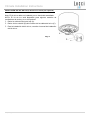
Este ventilador con sistema colgante puede ser instalado en un techo con una inclinación máxima de 20
grados. Img. 4
NOTA: Si está instalando el ventilador en un techo inclinado, puede que sea necesario utilizar una tija más
larga para mantener el espacio necesario entre el extremo del aspa y el techo.
NOTA: El ventilador de techo debe instalarse en un lugar donde los extremos de las aspas queden a 300 mm
como mínimo de las paredes y otros objetos.
NOTA: Para la instalación en techos inclinados, la abertura del soporte del ventilador (B) debe apuntar hacia
el pico del techo.
Para colgar su ventilador donde ya haya un elemento de instalación pero sin vigas, puede que necesite
instalar una barra para colgar (C) como la mostrada en la imagen 5. Asegúrese de que la barra de colgar que
adquiera haya sido diseñada para usarse con ventiladores de techo.
Img. 2
Img. 5
Img. 3
Img. 4
Techo inclinado
Máximo 20°

Climate Installation Instructions
14 | P a g e
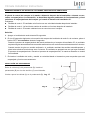
CÓMO COLGAR EL VENTILADOR
Pase los cables de la corriente (C) de la caja eléctrica (B) por el centro del soporte del ventilador (D). Instale
el soporte del ventilador (D) a la caja eléctrica (B) con los tornillos (F) incluidos con la caja eléctrica y las
arandelas (E) incluidas con el ventilador. Img. 6
Levante el conjunto del ventilador y cuélguelo en el soporte del ventilador. Asegúrese de que la ranura de
registro (A) de la bola de la tija esté posicionada sobre el tope (B) del soporte del ventilador (C) para que el
ventilador no pueda girar cuando esté funcionando. Img. 7
DIAGRAMA DE CONEXIONES ELÉCTRICAS
ADVERTENCIA: Para evitar posibles descargas eléctricas, asegúrese de que la corriente esté cortada en el
cuadro de distribución.
Siga los pasos siguientes para conectar el ventilador al cableado residencial. Utilice las tuercas de alambre
incluidas con su ventilador. Asegure los conectores con cinta aislante. Asegúrese de que no haya hilos de
cable o conexiones sueltos.
1. Conecte el cable de fase de la residencia (negro) al cable
de entrada del filtro EMI (negro, CA EN L) como muestra la
Img. 8.
2. Conecte cable neutro de la residencia (blanco) al cable
de entrada del filtro EMI (blanco, CA EN N).
3. Conecte el cable de tierra de la residencia al cable de
tierra del ventilador (verde). Conecte los conectores del cable
de tierra uno a otro.
4. Conecte el cable de salida del filtro EMI (negro, A
MOTOR L) al cable de entrada de fase (negro, A MOTOR L).
5. Conecte el cable de salida del filtro EMI (blanco, A
MOTOR N) al cable de entrada de neutro (blanco, A MOTOR
N).
6. Tras conectar los cables, apártelos unos de otros de
manera que los cables verdes y blancos queden a un lado de
la caja eléctrica y los cables negro y azul queden al otro lado.
7. Oriente las tuercas de alambre hacia arriba y empuje los
cables hacia el interior de la caja eléctrica.
Img. 6
Img. 7
Img. 8

Climate Installation Instructions
15 | P a g e
CÓMO FINALIZAR LA INSTALACIÓN
1. Empaque todas las conexiones con cuidado en la caja eléctrica
del techo.
2. Inserte el florón (A) hasta el soporte del ventilador y pase los
tornillos (D) del soporte del ventilador por los orificios de llave.
3. Gire el florón (A) hasta que la cabeza del tornillo (B) llegue al tope
de la sección más estrecha del orificio de llave (ver Img. 9).
4. Asegure el florón apretando los dos tornillos (D). A continuación,
instale la tapa del florón (E) al florón y asegúrela insertando los
tetones en los orificios (C).
NOTA: No sobreapriete los tornillos del soporte del ventilador.
INSTALACIÓN DE LAS ASPAS (Img. 10)
1. Acople el aspa (C) al kit de soporte del aspa (D) y asegúrela al soporte apretando los 3 tornillos (B).
2. Monte el conjunto del soporte del aspa al motor (F) y asegúrelo con los 2 tornillos del motor (E).
3. Repita estos pasos para instalar el resto de las aspas.
4. Por último, instale la cubierta inferior (H) al eje (G) del motor girándola en sentido horario.
Img. 9
Img. 10

Climate Installation Instructions
16 | P a g e
INSTALACIÓN DEL KIT DE LUZ (el kit de luz se vende por separado)
Nota: El kit de luz debe ser instalado por un electricista acreditado.
NOTA: El kit de luz está disponible para algunos modelos de
ventiladores de techo y es un kit opcional.
1. Retire la cubierta inferior del eje (A).
2. Retire el tubo retráctil (B) del conector de los cables de la luz (C).
3. Para la instalación del kit de luz, consulte el manual de instalación
del kit de luz.
Img. 11

Climate Installation Instructions
17 | P a g e
MODO DE EMPLEO DEL VENTILADOR DE TECHO
Emparejamiento del transmisor y el receptor - cuando hay dos o más ventiladores de techo CC
instalados en un mismo lugar
Cuando hay dos o más ventiladores próximos, se recomienda ajustar el transmisor/receptor de cada
ventilador con un código diferente, de manera que el funcionamiento de un ventilador no afecte el de otro.
Los interruptores DIP del transmisor (mando a distancia) están situados en el compartimento de las pilas del
transmisor. La configuración de los interruptores DIP permitirá asignar un código único a cada ventilador de
techo.
NOTA: Asegúrese de haber instalado un seccionador unipolar en el cableado fijo para cada ventilador.
NOTA: Asegúrese de que el receptor esté conectado a la corriente antes de emparejar el transmisor con el
receptor.
Emparejamiento del transmisor y el receptor del ventilador de techo 1:
Desconecte la corriente de los receptores de los ventiladores 1 y 2.
Instale una batería de 12V CC en el compartimento. Asegúrese de instalarla en el sentido correcto de la
polaridad. Img. 12
Cambie la posición de los interruptores DIP en el transmisor 1, de manera que sean diferentes a los del
transmisor 2.
Vuelva a conectar la corriente en el receptor 1. Mantenga el receptor 2 sin corriente. (Cada ventilador de
techo debe tener su propio seccionador, de manera que el ventilador de techo que necesite ser
emparejado con el transmisor siga recibiendo corriente).
En los 60 segundos siguientes a la conexión del receptor del ventilador de techo 1 a la corriente, pulse
el botón «SET» del transmisor 1 durante 6 segundos.
Durante el proceso de emparejamiento del mando a distancia y el receptor del ventilador CC, el ventilador
empezará a girar automáticamente en sentido antihorario a sus revoluciones máximas durante 3 minutos.
Cuando termine de girar en sentido antihorario, el ventilador cambiará de sentido automáticamente y
girará a sus máximas revoluciones otros 3 minutos. El ventilador se apagará una vez que haya finalizado
el proceso de emparejamiento. Durante el proceso de emparejamiento, el mando a distancia no tendrá
funcionalidad.
Encienda el ventilador 1 y cambie su velocidad desde el transmisor 1 para comprobar que está
emparejado y funciona correctamente.
Emparejamiento del transmisor y el receptor del ventilador de techo 2:
Desconecte la corriente de los receptores de los ventiladores 1 y 2.
Instale una batería de 12V CC en el compartimento. Asegúrese de instalarla en el sentido correcto de la
polaridad. Img. 12
Cambie la posición de los interruptores DIP en el transmisor 2, de manera que sean diferentes a los del
transmisor 1.
Vuelva a conectar la corriente en el receptor 2. Mantenga el receptor 1 sin corriente. (Cada ventilador de
techo debe tener su propio seccionador, de manera que el ventilador de techo que necesite ser
emparejado con el transmisor siga recibiendo corriente).

Climate Installation Instructions
18 | P a g e
En los 60 segundos siguientes a la conexión del receptor del ventilador de techo 2 a la corriente, pulse
el botón «SET» del transmisor 2 durante 6 segundos.
Durante el proceso de emparejamiento del mando a distancia y el receptor del ventilador CC, el ventilador
empezará a girar automáticamente en sentido antihorario a sus revoluciones máximas durante 3 minutos.
Cuando termine de girar en sentido antihorario, el ventilador cambiará de sentido automáticamente y
girará a las máximas revoluciones otros 3 minutos. El ventilador se apagará una vez que haya finalizado
el proceso de emparejamiento. Durante el proceso de emparejamiento, el mando a distancia no tendrá
funcionalidad.
Encienda el ventilador 2 y cambie su velocidad desde el transmisor 2 para comprobar que está
emparejado y funciona correctamente.
Nota: El emparejamiento del transmisor y el receptor no es necesario si solo se instala un ventilador
de techo. Cuando haya dos o más ventiladores de techo próximos unos a otros, consulte las
instrucciones anteriores.
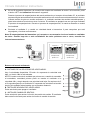
Botones del mando a distancia
A - BOTONES DE LA VELOCIDAD DEL VENTILADOR:
Hay 6 velocidades disponibles. El botón «I» representa la velocidad más
baja, y el botón «VI» la más elevada.
NOTA: Cuando encienda el ventilador por primera vez o cambie el encendido
al controlador, necesitará primero poner en marcha el ventilador a la
velocidad «VI» y elegir después una velocidad más baja. Se requieren de 5
a 10 segundos para que el ventilador CC responda a la velocidad o al sentido
de giro del ventilador seleccionados con el mando a distancia.
B - BOTÓN DE APAGADO DEL VENTILADOR:
Pulse este botón para apagar el ventilador.
C - BOTÓN DE CAMBIO DE SENTIDO:
Pulse este botón para activar la función de cambio de sentido. El ventilador
debe estar funcionando para activar la función de cambio de sentido.
Img. 12
Img. 13
Transmisor 1
Transmisor 2
Interruptores DIP
Ajustar a 0111
Interruptores DIP
Ajustar a 0100

Climate Installation Instructions
19 | P a g e
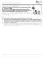
D - BOTÓN DE CONTROL DE LA LUZ: (El kit de luz se vende por separado)
Pulse este botón para apagar o encender la luz.
Mantenga pulsado el botón para acceder a las funciones de regulación de la luz.
E – INTERRUPTOR D/ON
El interruptor con el símbolo D/ON controla la función de regulación de las
luces. Si las bombillas utilizadas no son regulables, utilice un bolígrafo de punta
de bola o un destornillador pequeño para ajustar el interruptor a «D» y
deshabilitar la función de regulación de la luz. Si utiliza bombillas halógenas
regulables, ajuste el interruptor a «ON» para habilitar la función de regulación
de la luz. Img. 14
EL RECEPTOR PROPORCIONA LOS SIGUIENTES NIVELES DE PROTECCIÓN:
Posición de bloqueo: el receptor incorpora una función de seguridad para protegerlo en caso de
obstrucciones en el ventilador cuando está en funcionamiento. El motor se quedará bloqueado y se
desconectará de la corriente después de 30 segundos de interrupción. Por favor, retire los obstáculos
antes de volver a reanudar el funcionamiento del aparato. Para restablecer el ventilador, apague el motor
del ventilador y vuelva a encenderlo.
Protección sobre 80W: cuando el receptor detecta un consumo eléctrico superior a 80W, el receptor se
apagará y su funcionamiento se detendrá inmediatamente. Encienda el receptor después de 5 segundos
para reanudar el funcionamiento del ventilador.
Img. 14

Climate Installation Instructions
20 | P a g e
REEMPAREJAMIENTO DEL RECEPTOR Y EL MANDO A DISTANCIA DEL VENTILADOR
Si pierde el control del receptor o el mando a distancia después de la instalación o durante su uso,
vuelva a emparejarlos. A continuación, se describen algunos problemas de funcionamiento y cómo
solucionar el emparejamiento del receptor y el mando a distancia del ventilador CC.
Problemas:
Pérdida de control - El ventilador solo funciona a una velocidad elevada después de instalarlo
Pérdida de control - La función de cambio de sentido no funciona después de instalarlo
Pérdida de control - El mando a distancia no se comunica con el receptor
Solución:
A. Apague el ventilador de techo durante 30 segundos.
B. En los 60 segundos siguientes a la conexión del receptor del ventilador de techo 2 a la corriente, pulse el
botón «SET» del transmisor durante 6 segundos.
Durante el proceso de emparejamiento del mando a distancia y el receptor del ventilador CC, el ventilador
empezará a girar automáticamente en sentido antihorario a sus revoluciones máximas durante 3 minutos.
Cuando termine de girar en sentido antihorario, el ventilador cambiará de sentido automáticamente y
girará a las máximas revoluciones otros 3 minutos. El ventilador se apagará una vez que haya finalizado
el proceso de emparejamiento. Durante el proceso de emparejamiento, el mando a distancia no tendrá
funcionalidad.
C. Encienda el ventilador de techo y cambie su velocidad desde el transmisor para comprobar que está
emparejado y funciona correctamente.
INSTALACIÓN DEL PORTAMANDO
Retire la cubierta (A) del portamando (B). Instale el
portamando (B) con los dos tornillos (C) suministrados.
Vuelva a poner la cubierta (A) en el portamando (B). Img. 15
Img. 15

Climate Installation Instructions
21 | P a g e
DESPUÉS DE LA INSTALACIÓN
BAMBOLEO:
NOTA: Los ventiladores de techo tienden a moverse cuando están funcionando debido a que están montados
sobre una arandela de goma. Si el ventilador está montado rígidamente al techo, se podrían generar unas
vibraciones excesivas. Unos pocos centímetros de movimiento es bastante aceptable y NO indica que haya
un problema.
PARA REDUCIR EL BALANCEO DEL VENTILADOR: Compruebe que todos los tornillos que fijan el soporte
del ventilador y la tija esté bien apretados.
KIT DE BALANCEO: Se incluye un kit de balanceo para equilibrar el ventilador de techo en la instalación
inicial. Por favor, consulte las instrucciones sobre cómo usar el kit de balanceo. El kit de balanceo puede
usarse para reequilibrar el ventilador si se desequilibra de nuevo. Guarde el kit de balanceo después de la
instalación en caso de necesitarlo en un futuro.
RUIDO:
En los momentos de silencio (sobre todo por la noche), se pueden escuchar ruidos tenues ocasionalmente.
Las ligeras fluctuaciones de la corriente y las señales de frecuencia eléctrica superpuestas en el control del
agua caliente durante las horas no punta, puede causar cambios en el ruido del motor del ventilador. Esto es
algo normal. Por favor, permita un periodo de rodaje de 24 horas, transcurridos los cuales la mayoría de los
ruidos asociados con su nuevo ventilador deberán desaparecer. Todos los motores eléctricos son audibles
hasta cierto punto. Entienda que esto no es un fallo del producto y por lo tanto no está cubierto por la garantía.
CUIDADO Y MANTENIMIENTO:
La limpieza periódica de su ventilador de techo es el único mantenimiento que se requiere. Utilice un
cepillo blando o un paño sin pelusa para no arañar el acabado de pintura. Por favor, corte la corriente
cuando haga esto.
No utilice agua cuando limpie su ventilador de techo, dado que podría dañar el motor o las aspas y causar
posibles descargas eléctricas.
El motor tiene un rodamiento con lubricación permanente, por lo que no es necesario engrasarlo.
NOTA: Apague siempre el ventilador desde el interruptor de alimentación antes de limpiarlo.
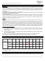
INFORMACIÓN TÉCNICA
Dimension
es del
ventilador
Velocidad
Voltios
(V)
Amper
ios
(A)
Vatios
(W)
RPM
CFM
CFM/
W
Peso
neto
(lb)
Peso
bruto
(lb)
C.F.
52” CD52
Extra alta
120
0,25
32,88W
217
5705.56
173.53
12.1
14.52
1.37
Moderadam
ente alta
120
0,12
13,17W
150
4172.71
316.83
12.1
14.52
1.37
Baja
120
0,05
2.78W
50
1266.19
455.46
12.1
14.52
1.37
Estos son medidas aproximadas. No incluyen datos de ninguna de las lámparas o luces que van instaladas
al ventilador de techo.
GARANTÍA
2 años de garantía para todo el ventilador. Por favor, consulte la tarjeta de garantía para más información.
-
 1
1
-
 2
2
-
 3
3
-
 4
4
-
 5
5
-
 6
6
-
 7
7
-
 8
8
-
 9
9
-
 10
10
-
 11
11
-
 12
12
-
 13
13
-
 14
14
-
 15
15
-
 16
16
-
 17
17
-
 18
18
-
 19
19
-
 20
20
-
 21
21
-
 22
22


Lucci Air 21052001 Instrucciones de operación
- Categoría
- Ventiladores domésticos
- Tipo
- Instrucciones de operación
- Este manual también es adecuado para
En otros idiomas
Documentos relacionados
-
Lucci Air 21050701 Instrucciones de operación
-
-
-
-
-
-
-
-
-
LUCCI Airfusion Radar DC Ceiling Fan Manual de usuario

