Ag Leader DLE0332W El manual del propietario
- Categoría
- Secadoras de ropa eléctricas
- Tipo
- El manual del propietario

MANUAL DEL PROPIETARIO
Secadora de Eléctrica y Gas
Gracias por comprar una secadora Completamente Automática LG.
Por favor lea su manual del propietario cuidadosamente, ya que
le proveerá de instrucciones sobre la segura instalación, manejo
y mantenimiento. Consérvelo para futuras referencias, archive
el modelo y números de serie de su secadora.
/
/
/
/
/
/
1-800-243-0000
para el Servicio LG (Atención al Cliente) 24 horas al día, 7 días a la semana

P/No.: 3828EL4001A
/
/
/
/
/
/
MANUAL DEL PROPIETARIO
Electric and Gas Dryer
1-800-243-0000
24 HOURS A DAY, 7 DAYS A WEEK FOR LG CUSTOMER SERVICE

TABLE OF CONTENTS
22
PART1. IMPORTANT WARRANTY AND SAFETY INSTRUCTIONS .................................................................3-5
PART2. INITIAL STEPS FOR INSTALLING YOUR DRYER .............................................................................6-11
Positioning the Dryer ...................................................................................................................................6
Procedure for Reversing the Door...............................................................................................................7
Connecting the Exhaust and Venting System.............................................................................................8
Connection of Gas Supply/Electrical Plug Connections for Electric Dryer Only..........................................9
Preparation of the Dryer/Confirming Heat Source Operation/Dryer Airflow ..............................................10
Additional Instructions for Installation of Your Dryer in a Manufactured or Mobile Home .........................11 .
PART3. ELECTRICAL REQUIREMENTS FOR ELECTRIC DRYER ...............................................................12-16
3-Wire Connection with a Power Supply Cord ..........................................................................................14
4-Wire Connection with a Power Supply Cord ..........................................................................................15
Optional 3-wire Connection .......................................................................................................................16
PART4. ELECTRICAL REQUIREMENTS FOR GAS DRYERS ............................................................................17
PART5. GAS REQUIREMENTS AND INSTRUCTIONS........................................................................................18
PART6. EXHAUST REQUIREMENTS AND MAINTENANCE..........................................................................19-20
PART7. FEATURES AND BENEFITS ..............................................................................................................21-26
Using Your Dryer/To use a Sensor Dry Cycle...........................................................................................22
To use a Manual Dryer Cycle/Stopping Your Dryer/Loading ....................................................................23
Cycle Descriptions.....................................................................................................................................24
Options/Modifiers ......................................................................................................................................25
Rack Dry/Beeper/Anti-Bacterial/Custom Programming.............................................................................26
PART8. TROUBLESHOOTING GUIDE ............................................................................................................27-29
LG DRYER LIMITED WARRANTY ........................................................................................................................30

3
Part 1 IMPORTANT WARRANTY AND SAFETY INSTRUCTIONS
3
SEEKING WARRANTY ASSISTANCE
WARNING!
For your safety, the recommendations in this manual must be followed. To reduce the risk
of fire or explosion, electric shock, or to prevent property damage, personal injury, or
death when using your appliance, follow basic precautions, including the following.
Warranty Service.
The warranty for your dryer is printed the end of this manual.
Warranty service is available by contacting your nearest LG Service Center and, for warranty period
from the date of purchase, if this dryer is installed and operated according to the instructions in this
manual, LG will repair or replace any of its mechanical or electrical parts if they are defective in
material or workmanship.
Warranty Restriction:
If the dryer is subjected to other than private family use, all warranty
coverage is effective for only 90 days.
You will need the complete model and serial numbers when requesting information. We recommend
that you staple your sales slip or cancelled check here, because proof of original purchase date is
needed to obtain warranty service. Your dryer’s model and serial numbers are located on the Model
and Serial Number Plate located on the front of the dryer behind the door.
Use the space below to record the model number and serial number of your new LG dryer.
Model No.
Serial No.
Date of Purchase
❈ Staple your receipt hear.
!

Part 1 IMPORTANT WARRANTY AND SAFETY INSTRUCTIONS
4
1) Read all instructions before using the appliance.
2) Do not dry articles that have come into contact with
gasoline, dry-cleaning solvents, or other flammable
or explosive substances, as they give off vapors that
could ignite or explode.
3) Do not allow children to play on or in the appliance.
Close supervision of children is necessary when
using the appliance.
4) Before the appliance is removed from service or
discarded, remove the door to the drying
compartment.
5) Do not reach into the appliance if the drum is
moving.
6) Do not install or store this appliance where it will be
exposed to the weather.
7) Do not tamper with controls.
8) Do not repair or replace any part of the appliance or
attempt any servicing unless specifically
recommended in the user-maintenance instructions.
9) Do not use heat to dry articles containing foam
rubber or similarly textured rubber-like materials.
10) Clean lint screen before or after each load.
11) Keep area around the exhaust opening and adjacent
surrounding areas free from the accumulation of
lint, dust, and dirt.
12) The interior of the appliance and exhaust duct
should be cleaned periodically by qualified service
personnel.
13) Do not place items exposed to cooking oils in your
dryer. Items contaminated with cooking oils may
contribute to a chemical reaction that could cause a
load to catch fire.
14) Do not use fabric softners or products to eliminate
static unless recommended by the manufacturer of
the fabric softner or product.
GROUNDING INSTRUCTIONS
This appliance must be grounded. In the event of
malfunction or breakdown, grounding will reduce the
risk of electric shock by providing a path of least
resistance for electric current. This appliance is
equipped with a cord having an equipment-grounding
conductor and a grounding plug. The plug must be
plugged into an appropriate outlet that is properly
installed and grounded in accordance with all local
codes and ordinances.
WARNING - Improper connection of the equipment-
grounding conductor can result in a risk of electric
shock. Check with a qualified electrician or service
person if you are in doubt as to whether the appliance is
properly grounded.
Do not modify the plug provided with the appliance: if
it will not fit the outlet, have a proper outlet installed by
a qualified electrician.
WARNING!
to help reduce any risk of electric shock, fire, or other personal or property injury
when using your dryer, please exercise care and follow basic safety precautions,
including the following:
!
IMPORTANT SAFETY INSTRUCTIONS
SAVE THESE INSTRUCTIONS

5
Part 1 IMPORTANT WARRANTY AND SAFETY INSTRUCTIONS
• Do not try to light a match, or cigarette, or
turn on any gas or electrical appliance.
• Do not touch any electrical switches. Do not
use any phone in your building.
• Clear the room, building or area of all
occupants.
• Immediately call your gas supplier from a
neighbor’s phone. Follow the gas supplier’s
instructions carefully.
• If you cannot reach your gas supplier, call the
fire department.
To reduce the risk of fire or explosion, electric
shock, property damage, personal injury, or death
when using this appliance, please follow all
instructions and information, including those in
this manual and instructions and information
provided by your gas supplier, including the
following:
• Do not store or use any gasoline, dry-cleaning
solvents, or any other flammable vapors or
liquids in the area surrounding this appliance.
• Do not dry anything that has ever had anything
flammable on it, even after washing.
• No washer can completely remove oil. Do not
dry any articles that have ever had any kind of
oil on them, including cooking oil.
• Articles containing foam, rubber, rubber like
materials, plastic, or similar materials should be
dried on a clothesline or by using an air cycle.
• Failure to follow these instructions can result in
fire, death, or serious injury.
• A qualified service person or company must
perform installation and service of this
appliance.
California Safe Drinking W
ater and
T
oxic Enforcement Act
This act requires the governor of California to
publish a list of substances known to the state to
cause cancer, birth defects or other reproductive
harm and requires businesses to warn customers
of potential exposure to such substances.
Gas appliances can cause minor exposure to four
of these substrances, namely benzene, carbon
monoxide, formaldehyde and soot, caused
primarily by the incomplete combustion of
natural gas or LP fuels.
Properly adjusted dryers will minimize
combustion. Exposure to these substances can be
minimized further by properly venting the dryer
to the outdoors.
WHAT TO DO IF YOU SMELL
GAS:
WARNING!
• Keep flammable materials and vapors, such
as gasoline, away from dryer.
• Place dryer at least 18 inches above the floor
for a garage installation.
• Failure to do so can result in death,
explosion or fire.
!
!
WARNING
!

Part 2 INITIAL STEPS FOR INSTALLING YOUR DRYER
6
5
0
.5
"
(1
2
8
.2
7
cm
)
42"3/4
(108.6 cm)
27"
(68.6 cm)
3
0
"
(7
6
.2
c
m
)
3"
(7.6 cm)
3"
(7.6 cm)
48"
2
(310 cm
2
)
24"
2
(155 cm
2
)
31.5"1"
(2.54 cm) (80.01 cm)
1"
(2.54 cm)
14" max
(35.6 cm)
18"
(45.72 cm)
27"
(68.6 cm)
0"
(0 cm)
0"
(0 cm)
The following instructions will help guide you through the initial steps of setting up your dryer for use.
Please note that every section of this manual provides important information regarding the preparation and
use of your dryer, and it is important that you review this entire manual before proceeding with any
installation or use. More detailed instructions concerning electrical connections, gas connections, and
exhaust requirements are provided at other parts of this manual.
Choose a location with a solid floor for your dryer.
Place the dryer at least eighteen inches above the
floor for a garage installation. After placing the
dryer in the desired location, please confirm that the
dryer has the required clearances through reference
to the following information and manual sections on
Exhaust Requirements and Maintenance.
If you are installing your dryer in a manufactured or
mobile home, please refer to STEP 9 below for
additional instructions.
Installing Y
our Dryer in a Closet or Recessed
Area. Following are instructions concerning and the
minimum clearances required for any closet, recessed
area, or customized under-counter installation:
• Additional spacing should be considered for
installation and servicing.
• Additional clearances might be required for wall,
door, and floor moldings.
• Additional spacing of 1 in. (2.5 cm) on all sides of
the dryer is recommended to reduce noise transfer.
• For closet installation with a door, minimum
ventilation openings in the top and bottom of the
door are required. Louvered doors with equivalent
ventilation openings are acceptable. Companion
appliance spacing should also be considered.
* Most installations require a minimum 5
1/2 in.
(14 cm) clearance behind the dryer for the exhaust
vent with elbow.
STEP 1: Positioning the Dryer.

7
Part 2 INITIAL STEPS FOR INSTALLING YOUR DRYER
Once in position, adjust the leveling legs of the dryer
until it is level from left to right and from front to
back. The leveling legs must remain firmly on the
floor and the dryer should not rock. The maximum
slope of the dryer from left to right or from front to
back should not exceed 2.5 cm (1 inch). If the dryer
is not level, and if the slope exceeds 2.5 cm (1 inch),
a load may not tumble properly and internal sensors
may malfunction. Note: Other sections of this
manual also provide important information
concerning the placement of and clearances for your
dryer. Please review this entire manual before
proceeding with any installation.
The door on your dryer may be installed to open
either to the left or the right. Follow these
procedures to reverse the direction in which your
door opens:
STEP 2: Procedure for Reversing
the Door
1
2
3

Part 2 INITIAL STEPS FOR INSTALLING YOUR DRYER
8
In addition to the following warnings, please refer
to manual section on Exhaust Requirements and
Maintenance. IMPORTANT: To reduce the risk of
fire, combustion, and gas accumulation, the dryer
must be vented to the outdoors. Please follow the
following instructions (and all others in this
manual) very carefully.
• Do not use thin plastic or foil ducting.
• Use 4" (10.2 cm) diameter rigid or flexible metal
duct (note: venting materials are not supplied with
the dryer, and you should obtain the venting
materials necessary for proper installation)
• Position the dryer so that the exhaust duct is as
short as possible
• Clean old ducts before installing this dryer
• The male end of each section of exhaust duct must
point away from the dryer
• Use as few elbow joints as possible
• Use duct tape on all duct joints
• Insulate ductwork that runs through unheated
areas in order to reduce condensation and lint
build-up on pipe walls; and
• PLEASE BE AWARE THAT FAILURE TO
EXHAUST THE DRYER CORRECTLY WILL
VOID THE DRYER’S WARRANTY.
STEP 3: Connecting the Exhaust
and Venting System.
WARNING!
• Use a heavy metal vent.
• Do not use a plastic vent.
• Do not use a metal foil vent.
• Failure to follow these instructions can
result in death or fire.
• Clean old ducts before installing this dryer
!
■ ALTERNATE EXHAUST DIRECTIONS
1. Remove screw & exhaust duct.
2. Detach and remove the bottom, left, or right
side knockout as desired.
(Right side vent not avilable on gas dryer.)
3. Reconnect the new duct[11 in(28cm)] to the
blower housing, and Fixing the duct to the
base.
4. Pre-assemble 4" elbow with 4" duct.
Wrap duct tape around joint.
5. Insert duct assembly, elbow first, through the
side opening and connect the elbow to the
dryer internal duct.
Attach
hole

9
Part 2 INITIAL STEPS FOR INSTALLING YOUR DRYER
(Gas dryer only). In addition to the following,
please refer to manual section on Gas Requirements
and Instructions.
1. Confirm that the type of gas available in your
laundry room is appropriate for the dryer. The
dryer is prepared for Natural Gas with a 3/8"
NPT gas connection.
2. Remove the shipping cap from the gas
connection at the back of the dryer. Make sure
that you don’t damage the threads of the gas
connection pipe when you remove the shipping
cap.
3. Connect the dryer to your laundry room’s gas
supply using a new flexible stainless steel
connector (as noted below, only use a new
stainless steel flexible connector if allowed by
your local codes).
4. Securely tighten all connections between the
dryer and your laundry room’s gas supply. Turn
on your laundry room’s gas supply and check all
pipe connections (both internal and external) for
gas leaks with a non-corrosive leak detection
fluid.
5. For LP (Liquefied Petroleum) gas connection,
refer to this manual’s section entitled Gas
Requirements and Instructions.
1. New stainless steel flexible connector. Use this type of
connector only if allowed by local codes. Use Design AGA
Certified Connector.
2. 1/8" NPT Pipe Plug (for checking inlet gas pressure)
3. Equipment Shut-Off Valve-
Installed within 6’ (1.8 m) of dryer
4. Iron Pipe. Shorter than 20’ (6.1 m)
Use 3/8" pipe. Longer than 20’ (6.1 m) - Use 1/2" pipe.
5. 3/8" N.P.T. Gas Connection
STEP 4: Connection of Gas Supply
Following are several warnings and instructions
concerning making the electrical connection for
electric dryers. More detailed information
concerning the electrical connection is provided at
the manual section entitled Electrical Requirements
For Electric Dryer and it is important that you
thoroughly review that section, and the remainder of
this manual, before taking any steps to install or use
this dryer.
1. Use only a new U.L. listed No. 10 (copper wire
only) three conductor power supply cord kit rated
240 Volts (minimum) 30 Amperes and labeled as
suitable for use in a clothes dryer.
2. Four-wire cord is required for manufactured
(mobile) home installations and use and where
local codes do not allow grounding of this
appliance through neutral.
3. The wiring diagram is provided inside the dryer
control hood. Label all wires prior to
disconnection when servicing the dryer, because
wiring errors can cause serious injury to you and
your dryer.
4. For additional instruction on connecting the dryer
to an electrical power source, please refer to this
manual’s section on Electrical Requirements and
Electric Dryer.
STEP 5: Electrical Plug Connections
for Electric Dryer Only.
2
3
5
1
4
WARNING!
• Use a new UL approved 30 amp power
supply cord or 10 gauge solid copper wire.
• Use a UL approved strain relief.
• Disconnect power before making electrical
connections.
• Connect neutral wire(white or center wire) to
center terminal.
• Ground wire(green or bare wire) must be
connected to green ground connector.
• Securely tighten all electrical connections
• See installation instructions for complete
instructions.
• Failure to do so can result in fire or electrical
shock.
!

Part 2 INITIAL STEPS FOR INSTALLING YOUR DRYER
10
Prior to first use of this appliance, use an all-
purpose cleaning product, or a solution of detergent
and water, with a damp clothe to remove from the
inside of the dryer drum/drying compartment any
dust or dirt that may have accumulated inside of the
dryer. Plug in your dryer after reviewing the
following parts on your dryer’s Electrical
Requirements.
STEP 6: Preparation of the Dryer.
Effective dryer operation requires appropriate dryer
airflow. The adequacy of the airflow can be
measured by evaluating the static pressure. Static
pressure in the exhaust duct can be measured with a
manometer, placed on the exhaust duct
approximately 2 ft. (60.9 cm) from the dryer. Static
pressure in the exhaust duct should not exceed 0.6
inches (1.5 cm). The dryer should be checked with
the dryer running with no load.
STEP 8: Dryer Airflow.
Confirming Heat Source in Gas Dryers
Close the door to the dryer drum/drying
compartment and, after completing all steps in this
manual for proper installation of this dryer, start the
dryer on a heat setting, as described more fully in
the operating instructions that accompany the dryer.
After the dryer starts, the igniter will glow red and
the main burner will ignite.
Warning: If all air is not purged from the gas line,
the gas igniter may go off before the gas and the
main burner have ignited. If this happens, the
igniter will re-attempt gas ignition after
approximately two minutes.
Confirming Heat Source in Electric Dryers
Close the door to the dryer drum/drying
compartment and, after completing all steps in this
manual for proper installation of this dryer, start the
dryer on a heat setting, as described more fully in
the operating instructions that accompany the dryer.
The exhaust air or the exhaust pipe should be warm
after the dryer has been operating for three minutes.
STEP 7: Confirming Heat Source
Operation.
1
2
Measuring Static pressure
0.6 inches (1.5 cm)
MAXIMUM STATIC
PRESSURE IN
WATER COLUMN
1 Manometer
2 Exhaust Duct

11
Part 2 INITIAL STEPS FOR INSTALLING YOUR DRYER
The following instructions are applicable to
installations of the dryer in a manufactured or
mobile home. Any installation in a manufactured or
mobile home must comply with the Manufactured
Home Construction and Safety Standards Title 24
CFR, Part 32-80 or Standard CAN/CSA0Z240 MH
and local codes and ordinances. If you are
uncertain whether your proposed installation will
comply with these standards, please contact a
service and installation professional for assistance.
The following instructions apply to any installation
of the dryer in a manufactured or mobile home:
1) The gas dryer must be permanently attached to
the floor.
2) The electrical connection for an electric dryer
must be a 4-wire connection. More detailed
information concerning the electrical connection
is provided at the manual section entitled
Electrical Requirements for Electric Dryer
3) To reduce the risk of combustion and fire, the
dryer must be vented to the outside.
4) Electric dryers may be vented to the outside
using the back, left, right, or bottom panel.
5) Gas dryers may be vented to the outside using the
back, left, or bottom panel. Gas dryer may not be
vented to the outside using the right side panel
because of the burner housing.
6) The dryer exhaust duct must be affixed securely
to the manufactured or mobile home structure,
and the exhaust duct must be made of a material
that will resist fire and combustion, and it is
recommended that you use a rigid or flexible
metal pipe.
7) DO NOT connect the exhaust duct with any other
duct, vent, chimney, or other exhaust duct.
8) Make sure the dryer has adequate access to
outside fresh air to ensure proper operation. The
opening for outside fresh air must be at least 25
in
2
(163 cm
2
).
9) It is important that the clearance of the duct from
any combustible construction be at least 2 inches
(5 cm), and, when venting the dryer to the
outdoors, the dryer can be installed with a
clearances of 1 inch at the sides and back of the
dryer.
10) Please be aware that venting materials are not
supplied with the dryer. You should obtain the
venting materials necessary for proper
installation.
STEP 9: Additional Instructions for
Installation of Your Dryer
in a Manufactured or
Mobile Home.
WARNING!
DO NOT connect exhaust ducts with
metal screws or fasteners that extend
into the duct.
!
WARNING!
DO NOT vent the exhaust duct under the
manufactured or mobile home.
!

Part 3 ELECTRICAL REQUIREMENTS FOR ELECTRIC DRYERS
12
Following are additional instructions regarding electrical connections and requirements for electric dryers.
Important Warning: To help prevent fire, electric shock, serious injury or death, the wiring and grounding
must conform to the latest edition of the National Electrical Code, ANSI/NFPA 70 and all applicable local
regulations. Please contact a qualified electrician to check your home’s wiring and fuses to ensure that your home
has adequate electrical power to operate the dryer.
120V/208V, 60 Hertz, 3-Wire Installation
120V/ 240V, 60 Hertz, 3-Wire Installation
!
Instructions for Grounding of your Electric
Electric Dryer:
a) Please note that the wiring diagram is provided
inside the dryer control hood.
b) This dryer must be connected to a grounded
metal, permanent wiring system; or an
equipment-grounding conductor must be run
with the circuit conductors and connected to the
equipment-grounding terminal or lead on the
dryer.
c) The dryer has its own terminal block that must
be connected to a separate branch, 60 Hertz,
single phase circuit, AC (alternating current)
circuit, fused at 30 Amperes (the circuit must be
fused on both sides of the line). ELECTRICAL
SERVICE FOR THE DRYER SHOULD BE
OF MAXIMUM RATE VOLTAGE LISTED
ON THE NAMEPLATE. DO NOT CONNECT
DRYER TO 110, 115, OR 120 VOLT
CIRCUIT. Heating elements are available for
field installation in dryers which are to be
conected to electrical service of different
voltage than that listed on nameplate, such as
208 Volt.
d) If branch circuit to dryer is fifteen feet (4.50 m)
or less in length, use U.L. (Underwriters
Laboratories) listed No. 10 A.W.G. wire
(copper wire only), or as required by local
codes. If over fifteen feet (4.50 m), use U.L.
(Underwriters Laboratories) listed No. 8
A.W.G. wire (copper wire only), or as required
by local codes. Allow sufficient slack in wiring
so dryer can be moved from its normal location
when necessary.
e) The power cord (pigtail) connection between wall
receptacle and dryer terminal block IS NOT
supplied with dryer. Type of pigtail and gauge of
wire must conform to local codes and with
instructions mentioned on the following pages.
f) The method of wiring the dryer is optional and
subject to local code requirements. Refer to
examples on next page.
g) You must select the method by which to wire
your dryer according to local code and ordinance
requirements. Sample methods are included in
the following pages.
WARNING!
Label all wires prior to disconnection
when servicing the dryer, because
wiring errors can cause serious injury
to you and your dryer.
!

13
Part 3 ELECTRICAL REQUIREMENTS FOR ELECTRIC DRYERS
Use the instructions at this section if your home has
a 3-wire receptacle (NEMA type 10-30R) and you
will be using a UL listed, 120/240 volt minimum,
30 amp, dryer power supply cord.
Review the following options to determine the appropriate electrical connection
for your home:
Important: If your local codes or ordinances do not allow the connection of a frame-
grounding conductor to the neutral wire, use the instructions under Option 3: Optional
3-wire connection.
3-wire receptacle
(NEMA type10-30R)
Use the instructions at this section if your home has
a 4-wire receptacle (NEMA type 14-30R) and you
will be using a UL listed, 120/240 volt minimum,
30 amp, dryer power supply cord.
4-wire receptacle
(NEMA type14-30R)

Part 3 ELECTRICAL REQUIREMENTS FOR ELECTRIC DRYERS
14
a. 3-wire receptacle (NEMA type 10-30R)
b. 3-wire plug
c. Neutral prong
d. Spade terminals with up turned ends
e. 3/4 in. (1.9 cm) UL approved strain relief
f. Ring terminals
g. Neutral (white or center wire)
a. External ground connector
b. Neutral grounding wire (green)
c. Center silver-colored terminal block screw
d. Neutral wire (white or center wire)
e. 3/4 in. (1.9 cm) UL-listed strain relief
1. Loosen or remove center terminal block screw.
2. Connect neutral wire (white or center wire) of
power supply cord to the center, silver colored
terminal screw of the terminal block. Tighten
screw.
3. Connect the other wires to outer terminal block
screws. Tighten screws.
4. Tighten strain relief screws.
5. Insert tab of terminal block cover into slot of
dryer rear panel. Secure cover with hold-down
screw.
d
gf
a
lf your local codes or ordinances permit the
connection of a frame-grounding conductor to the
neutral wire, use these instructions. If your local
codes or ordinances do not allow the connection of
a frame-grounding conductor to the neutral wire,
use the instructions under Section 3: Optional
3-wire connection.
Option 1: 3-Wire Connection with
a Power Supply Cord

15
Part 3 ELECTRICAL REQUIREMENTS FOR ELECTRIC DRYERS
a. 4-wire receptable (NEMA type 14-30R)
b. 4-pront plug
c. Ground prong
d. Neutral Prong
e. Spade terminals with upturned ends
f. 3/4 in. (1.9 cm) UL approved strain relief
g. Ring terminals
a. External ground connector - Dotted line
shows position of NEUTRAL ground wire
before being moved to center terminal block
screw
b. Center silver-colored terminal block screw
c. Green wire of harness
1. Remove center terminal block screw.
2. Remove appliance ground wire (green) from
external ground connector screw. Fasten it under
the center, silver colored terminal block screw.
3. Connect ground wire (green or bare) of power
supply cable to external ground conductor screw.
Tighten screw.
4. Connect neutral wire (white or center wire) of
power supply cord to the center, silver colored
terminal screw of the terminal block.
a. External ground connector
b. Green or bare copper wire of power supply cord
c. 3/4 in. (1.9 cm) UL-listed strain relief
d. Center silver-colored terminal block screw
e. Neutral grounding wire (green)
f. Neutral wire (white)
5. Connect the other wires to outer terminal block
screws. Tighten screws.
6. Tighten strain relief screws.
7. Insert tab of terminal block cover into slot of
dryer rear panel. Secure cover with hold-down
screw.
• lf your local codes or ordinances do not allow the
use of a 3 wire connection, or you are installing
your dryer in a mobile home, you must use a 4-
wire connection.
Option 2: 4-wire connection with a
Power supply cord.

16
Part 3 ELECTRICAL REQUIREMENTS FOR ELECTRIC DRYERS
• If your local codes or ordinances do not allow the
connection of a frame-grounding conductor to the
neutral wire, use the instructions under this
section.
1. Remove center terminal block screw.
2. Remove appliance ground wire (green) from
external ground connector screw. Connect
appliance ground wire and the neutral wire (white
or center wire) of power supply cord/cable under
center, silver colored terminal block screw.
Tighten screw.
3. Connect the other wires to outer terminal block
screws. Tighten screws.
4. Tighten strain relief screws.
5. Insert tab of terminal block cover into slot of
dryer rear panel. Secure cover with hold-down
screw.
6. Connect a separate copper ground wire from the
external ground connector screw to an adequate
ground.
Option 3: Optional 3-wire
connection.
a. External ground connector
b. Neutral grounding wire (green)
c. Neutral wire (white or center wire)
d. Grounding path determined by a qualified electrician

17
Part 4 ELECTRICAL REQUIREMENTS FOR GAS DRYERS
120 Volt, 60 Hertz, with 3-Prong Grounding Plug
Following are additional instructions regarding electrical connections and requirements for gas dryers.
Important Warning: To help prevent fire, electric shock, serious injury or death, the wiring and grounding
must conform to the latest edition of the National Electrical Code, ANSI/NFPA 70, or the Canadian Electrical
Code, CSA C22.1, and all applicable local regulations. Please contact a qualified electrician to check your home’s
wiring and fuses to ensure that your home has adequate electrical power to operate the dryer.
Electrical Requirements for Your Dryer:
!
a) Please note that the wiring diagram is provided
inside the dryer control hood. Label all wires
prior to disconnection when servicing the dryer,
because wiring errors can cause serious injury to
you and your dryer.
b) Your dryer is designed to be used on a separate
branch, polarized, three-wire, effectively
grounded, 120 Volt, 60 Hertz, AC (alternating
current) circuit protected by a 15 Ampere fuse,
equivalent fusetron or circuit breaker.
c) Use separately fused circuits for washers and
dryers, and DO NOT operate a washer and a
dryer on the same circuit.
a) The dryer has a three-prong plug to help guard
against shock. The plug should be plugged
directed into a properly grounded three-prong
receptacle that is rated 120 Volts AC (alternating
current) 15 Amps. This plug, in order to be
properly and fully effective, must be plugged into
a properly installed outlet that is grounded in
accordance with all local codes and ordinances.
b) The dryer must be grounded in order to reduce
the risk of electric shock, including a
malfunction or breakdown.
c) If your laundry room does not meet the
specifications required by this manual, or if you
are uncertain whether or not your laundry room
meets these specifications, please have a
qualified service person or company, for example
a qualified electrician or your local electric
company, review your laundry room’s electrical
supply for any problems.
WARNING!
Do not overload the circuit by operating other
appliances on the same circuit when this
appliance is operating, by using an extension
cord to connect the dryer to the power
source, or by using any adapter to allow
additional cords to connect to the same
outlet.
!
STANDARD 120 VOLT, 60 HERTZ, 3-WIRE
EFFECTIVELY GROUNDED CIRCUIT
1 L1
2 Ground
3 Neutral Side
4 Round Grounding Prong
5 Neutral
2
1
3
5
4
V.A.C.
120
+ 12
0
V.A.C.
120
± 12
V.A.C
WARNING!
DO NOT modify the plug provided with the
dryer. If it does not fit the outlet in your
laundry room, a proper outlet will need to be
installed in your laundry room by a qualified
service person or company.
!

18
Part 5 GAS REQUIREMENTS AND INSTRUCTIONS
Following are important instructions and information concerning the requirements for the gas supply and service for
gas dryers. Important Warning: The gas supply and service for a gas dryer must comply with all local codes
and ordinances. In the absence of any local codes or ordinances in your area, the gas supply and service for your gas
dryer must comply with the latest edition of the National Fuel Cas Code, ANSI Z223.1/NFPA 54.
1. Gas supply requirements: Liquefied Petroleum
(L.P.) Gas (2,500 Btu/ft3 (93.1 MJ/m3)) service
must be provided at 10 + 1.5 in. water column
pressure.
2. Important: DO NOT connect the dryer to the
Liquefied Petroleum (LP) Gas service without
converting the gas value.
3. A qualified technician must perform the LP Gas
conversion. Contact your local gas service branch
if you require additional assistance or
information.
4. Isolate the dryer from the gas supply piping
system by closing its individual manual shut-off
valve, during any pressure testing of the gas
supply system at test pressure equal to or less
than 2/1 psi (3.45 kPa).
5. Supply Line Requirements. Your laundry room
must have a rigid gas supply line to your dryer.
In the United States, an individual manual shutoff
valve MUST be installed within at least 6 feet
(1.8m) of the dryer, in accordance with the
National Fuel Gas Coide ANSI Z223.1. A 1/8 in.
N.P.T. pipe plug must be installed as shown.
6. If using a rigid pipe, the rigid pipe should be 1/2
inch IPS. If acceptable under local codes and
ordinances and when acceptable to your gas
supplier, 3/8 inch approved tubing may be used
where lengths are less than 20 feet (6.1m).
Larger tubing should be used for lengths in
excess of 20 feet (6.1m). It is also important that
you use pipe joint compound that is insoluble in
LP gas.
7. To reduce the danger of gas leaks, explosion, and
fire, please follow and observe the following
instructions and WARNINGS:
• Connect the dryer to the type of gas shown on the
nameplate;
• Use new flexible stainless steel connectors;
• Use Teflon tape and pipe joint compound
insoluble in LP gas on all pipe threads;
• Purge gas supply of air and sediment before
connecting the gas supply to the dryer; in order to
prevent gas valve contamination, before tightening
connection between gas supply and dryer, purge
remaining air until odor of gas is identified; and
• DO NOT use an open flame to inspect for gas
leaks; instead, use a non-corrosive leak detection
fluid.
WARNING!
• Use a new AGA or CSA approved gas
supply line.
• Install a shut-off valve.
• Securely tighten all gas connections.
• If connected to LP, have a qualified person
make sure gas pressure does not exceed
13 in. water column.
• Examples of a qualified person include
licensed heating personnel, authorized gas
company personnel, and authorized service
personnel.
• Failure to do so can result in death,
explosion, or fire.
!
WARNING!
DO NOT attempt any disassembly of the
dryer, any disassembly requires the
attention and tools of an authorized and
qualified service person or company.
!
!

19
Part 6 EXHAUST REQUIREMENTS AND MAINTENANCE
Following are important instructions and information concerning the exhaust requirements for your dryer.
Important Warning: To reduce the risk of fire, combustion, or accumulation of combustible gases, DO NOT
exhaust dryer air into an enclosed and unventilated area, such as an attic, wall, ceiling, crawl space, chimney, gas
vent, or concealed space of a building. To reduce the risk of fire, DO NOT exhaust the dryer with plastic or thin foil
ducting.
Exhaust Requirements and Instructions:
1. Venting materials are not provided with the dryer
and you should obtain the necessary venting
materials locally. For example, the outer end of
exhaust pipe must have a weather hood with
hinged dampers to prevent back-draft when the
dryer is not in use.
2. The exhaust duct must be four inches (10.2 cm)
in diameter with no obstructions. The exhaust
duct should be kept as short as possible. Make
sure to clean any old ducts before installing your
new dryer.
3. Rigid metal duct is recommended. Do not install
flexible duct in concealed spaces.
Non-combustible flexible metal duct is
acceptable. Do not use plastic or thin foil ducting.
4. DO NOT use sheet metal screws on exhaust pipe
joints or other fastening means which extend into
the duct that could catch lint and reduce the
efficiency of the exhaust system. Secure all joints
with duct tape.
5. To maximize operating results, please observe the
duct length limitations noted in the chart above.
!
Number of 90°
Elbows
Weather Hood
Type
Recommended
Maximum length of 4”
(10.2 cm) diameter rigid
metal duct
Maximum length of 4”
(10.2 cm) diameter
flexible metal duct
NOTE : Deduct 6 feet (1.8 m) for each additional elbow.
It is not recommended to use more than 4 90° elbows.
Use Only for Short Run
Installations
0
1
2
3
4
0
1
2
3
4
65 feet (19.8 m)
55 feet (16.8 m)
47 feet (14.3 m)
36 feet (11.0 m)
28 feet (8.5 m)
45 feet (13.7 m)
35 feet (10.7 m)
30 feet (9.1 m)
25 feet (7.6 m)
20 feet (6.1 m)
55 feet (16.8 m)
47 feet (14.3 m)
41 feet (12.5 m)
30 feet (9.1 m)
22 feet (6.7 m)
35 feet (10.7 m)
27 feet (8.2 m)
21 feet (6.4 m)
17 feet (5.2 m)
15 feet (4.5m)
4”
(10.2 cm)
4”
(10.2 cm)
2-1/2”
(6.35 cm)

20
Part 6 EXHAUST REQUIREMENTS AND MAINTENANCE
Exhaust and Dryer Maintenance
1. After one year of use, the interior and complete
exhaust system of the dryer should be examined
and cleaned if necessary.
2. You should inspect and clean the exhaust duct at
least yearly.
3. Check the weather hoods frequently to ensure
the dampers are moving freely, that the dampers
are not pushed in and that nothing has been set
against the dampers.
4. A qualified service person or company should be
used to perform this maintenance.
5. A Flexible Metal Vent Kit, available at extra cost,
can be used to exhaust the dryer when it is placed
in hard to reach places. This Kit comes in two
pieces, one of which is attached to the dryer and
the other is attached to the wall exhaust outlet.
Following attachment of the two separate pieces
to the dryer and the wall, the dryer may be
returned to its final position, after which the two
pieces themselves can be connected.
7. Ordinarily, the dryer drum will need no care.
Wipe the exterior of the dryer as required, and
always immediately wipe the exterior of the
dryer in the event any detergent, bleach, or other
washing products is spilled on the dryer, because
these products may cause permanent damage to
the exterior finish of the dryer.
8. Clean the control panel with a damp cloth as
necessary. Warning: spray pre-wash products
may damage the finish of the control panel.
9. Please clean the lint filter either before drying
each load or after drying each load.
10. Always make sure the lint filter is clean before
starting a new load, because a clogged lint filter
may increase drying times.
11. Annually remove the lint filter and attach it to
the vacuum duct. See item #2 above.
12. Please note that the wiring diagram is provided
inside the dryer control hood. Label all wires
prior to disconnection when servicing the dryer,
because wiring errors can cause serious injury
to you and your dryer.
Cleaning the Lint Screen
1. Clean the lint filter either before drying each load
or after drying each load. Always make sure the
lint filter is clean before starting a new load,
because a clogged lint filter may increase drying
times.
2. To clean, pull the lint screen straight up and roll
any lint off the screen with your fingers. Do not
rinse or wash screen to remove lint, because wet
lint is hard to remove. Push the lint screen firmly
back into place.
3. Always ensure the lint screen is firmly secured
before running the dryer. Running the dryer with
a loose lint screen may cause overheating and
damage to the dryer and articles being dried.
4. Some articles may shed more lint than other
towels (for example, towels made of synthetic
fibers and natural fibers), causing the lint screen
to become congested more quickly. Remove lint
from the lint screen before and after drying these
articles, such as new towels.
5. In the event lint falls off of the lint screen and
into the dryer during removal, inspect the exhaust
hood and remove any lint.
6. Laundry detergent and fabric softener residue can
build up on the lint screen, causing longer drying
times. The screen is likely blocked if lint falls off
the screen. In order to prevent this type of build
up, and help ensure proper operation of your
dryer, clean the lint screen with a nylon brush
every six months or, if necessary, more
frequently. The lint filter can also be washed as
follows:
a) After rolling the lint off of the screen with your
fingers, wet both sides of the screen with hot or
warm water.
b) Wet a nylon brush with hot water and liquid
detergent and scrub the lint screen with the brush
to remove the buildup of detergent and fabric
softener.
c) Repeat as necessary.
d) After the residue has been removed, rinse screen
with hot water.
e) After drying the lint screen with a clean towel,
firmly replace the lint screen in your dryer.
WARNING!
Disconnect the dryer’s electric power prior
to any cleaning or maintenance.
!

21
Part 7 FEATURES AND BENEFITS
■ DLE5911W / DLG5911W
■ DLE2511W / DLG2511W
Following are instructions for starting and using your new dryer. Please refer to specific sections of this manual for
more detailed information. Important Warning: To reduce the risk of fire, electric shock, or injury to person, read
this entire manual, including the Important Safety Instructions, before operating this dryer.
WARNING!
Fire Hazard
No washer can completely remove oil.
Do not dry anything that has ever had any
type of oil on it (including cooking oils).
Items containing foam, rubber, or plastic
must be dried on a clothesline or by using
an Air Cycle. Failure to follow these
instructions can result in death or fire.
!
WARNING!
Explosion Hazard
Keep flammable materials and vapors, such
as gasoline, away from dryer.
Do not dry anything that has ever had
anything flammable on it (even after washing).
Failure to follow these instructions can result
in death, explosion, or fire.
!

22
Part 7 FEATURES AND BENEFITS
■ DLE5932W / DLG5932W / DLE0332W / DLG0332W/ DLE5932S / DLG5932S
■ DLE2532W / DLG2532W
STARTING YOUR DRYER
1. Clean lint screen before or after each cycle.
2. Place laundry into dryer and shut door.
See Loading.
3. Turn the knob to select the drying cycle you
want. The preset settings for Sensor Dry Cycles
or Manual Cycles will glow. The estimated or
actual cycle time (in minutes) will show in the
display.
1. Using Your Dryer
• Select an Sensor Dry Cycle.
• Select DRY LEVEL to adjust how dry you want
the load. As the cycle runs, the control senses the
dryness of the load and adjusts the time
automatically for the selected dryness level.
• Select the desired Options.
• Press START/PAUSE
NOTE: DRY LEVEL selections can only be made
while using Sensor Dry Cycles. Selecting MORE
Dry or LESS Dry automatically adjusts the sensed
time needed.
2. To use a Sensor Dry Cycle
DLE5911W/G5911W
DLE5932W/G5932W
DLE0332W/G0332W
DLE5932S/G5932S
DLE2511W/G2511W
DLE2532W/G2532W

23
Part 7 FEATURES AND BENEFITS
• Select a Manual Dry Cycle.
• Press MORE TIME or LESS TIME until the
desired drying time is displayed. Tap MORE
TIME or LESS TIME and the time will change by
1 minute intervals.
NOTE: The MORE TIME or LESS TIME
feature can be used with Manual Dry, Time Dry,
and Rack Dry Cycles.
• Press TEMP. CONTROL until the desired
temperature indicator glows.
• (OPTIONAL STEP) If desired, select OPTIONS.
For more details, see Options.
• Press START/PAUSE. Be sure the door is closed.
• If you do not press START/PAUSE within 10
minutes of selecting the cycle, the dryer
automatically shuts off.
• If you wish to end your drying cycle after pressing
START/PAUSE, press START/PAUSE again.
3. To use a Manual Dry Cycle
Properly loading your dryer can lower your utility
bill and prolong the life of your garments.
Loading suggestions
Load the dryer by the amount of space items take
up, not by their weight.
Do not overload the dryer. This causes uneven
drying and wrinkling.
Heavy Work Clothes
4 jeans
4 workpants
4 work shirts
2 sweatpants
2 sweatshirts
Towels
10 bath towels
10 hand towels
14 wash cloths
Mixed Load
3 sheets (1 king, 2 twin)
4 pillowcases
3 shirts
3 blouses
9 T-shirts
9 shorts
10 handkerchiefs
Following are sample loads for Super Capacity
Dryers:
5. Loading
To stop your dryer at any time
Press START/PAUSE or open the door.
Pausing or Restarting
To pause the dryer at any time
Open the door or press START/PAUSE once.
To restart the dryer
Close the door. Press START/PAUSE.
NOTE: Drying will continue from where the cycle
was interrupted if you close the door and press
START within 10 minutes. If the cycle is
interrupted for more than 10 minutes, the dryer will
shut off. Select new cycle settings before restarting
the dryer.
Child Lock
This feature allows you to lock your settings to
prevent children from changing them. You can also
use the child lock feature to prevent unintended
cycle or option changes during dryer operation.
To enable the Child Lock feature:
Press and hold RACK DRY and ANTI
BACTERIAL for 2 seconds. A single BEEP Tone is
heard, and CL is displayed. To unlock, press and
hold RACK DRY and ANTI BACTERIAL for 2
seconds. The indicator light turns off.
4. Stopping Your Dryer

24
Part 7 FEATURES AND BENEFITS
Select the drying cycle that matches the type of load
you are drying.
(See Sensor Dry or Manual Preset Cycle Settings
charts.)
Sensor Dry Cycles allow you to match the cycle to
the load you are drying. Each cycle dries certain
fabrics at the recommended temperature. A sensor
detects the moisture in the load and automatically
adjusts the drying time for optimal drying
• Heavy Duty
Use this cycle to get high heat for heavy fabrics
such as jeans, corduroys, or work clothes.
• Cotton/Towels
Use this cycle to get medium-high heat for drying
denims and towels.
• Normal
Use this cycle to get medium heat for drying
sturdy fabrics such as work clothes, casual clothes,
and cotton jerseys.
• Perm. press
Use for permanent press and synthetic items.
• Delicate
Use this cycle to get low heat for drying synthetic
fabrics, washable knit fabrics, and no-iron
finishes.
• Ultra Delicate
Use this cycle to get ultra low heat to gently dry
items such as lingerie, exercise wear, or sheer
curtains.
* Estimated Time with SENSOR DRY LEVEL
(Normal) setting.
Sensor Dry
Cycles Load Type
Temp.
High
Medium
High
Medium
Low
Low
Ultra
Low
Time*
(Minutes)
54
55
41
36
32
34
Sensor Dry Cycle
Use Manual Cycles to select a specific amount of
drying time and a drying temperature. When a
Manual Cycle is selected, the ESTIMATED TIME
REMAINING display shows the actual time
remaining in your cycle. You can change the actual
time in the cycle by pressing MORE TIME or LESS
TIME.
• Speed Dry
Use this cycle for drying small loads or loads that
need a short drying time.
• Freshen Up
Use this cycle to remove wrinkles from items,
such as clothes packed in a suitcase or items
wrinkled from being left in the dryer too long.
• Air Dry
Use the Air Dry Modifier for items that require
drying without heat such as rubber, plastic and
heat-sensitive fabrics.
Manual Cycles
HEAVY DUTY
Heavyweight, jeans
COTTON/TOWELS
Denim pants, towel
NORMAL
Corduroys, work clothes
PERM. PRESS
Permanent press,
synthetics
DELICATE
Sheets, lingerie, blouses
ULTRA DELICATE
Exercise wear, sheer
curtains, lace
Sensor Dry Preset Cycle Settings
6. Cycle Descriptions

25
Part 7 FEATURES AND BENEFITS
• Time Dry
Use this cycle to complete drying if items are still
damp after an Sensor Dry Cycle. Time dry is also
useful for drying heavyweight and bulky items,
such as bedspreads and work clothes.
Select DAMP DRY BEEP to alert you that your
clothes are approximately 80% dry. This is useful
when you want to remove lightweight items in a
mixed load to prevent overdrying or remove
partially dry items that may need ironing.
NOTE: The Damp Dry Beep is only available with
the Sensor Dry Cycles.
Damp Dry Beep
WRINKLE CARE prevents wrinkles that form
when you cannot unload the dryer promptly at the
end of a cycle. During this option, the dryer will
periodically tumble.
• Press WRINKLE CARE to get up to 3 hours of
heat-free, periodic tumbling at the end of a cycle.
• Stop WRINKLE CARE at any time by pressing
WRINKLE CARE or opening the dryer door.
NOTE: If you do not select WRINKLE CARE, the
dryer stops after cool down.
WRINKLE CARE
This chart shows examples of items that can be
dried using AIR DRY.
Reset cycle to complete drying, if needed.
• Check to see that coverings are securely stitched.
• Shake and fluff pillows by hand periodically
during the cycle.
• Dry item completely. Foam rubber pillows are
slow to dry.
NOTE: Air Dry is not available with Sensor Dry
Cycles.
When using Air Dry
Manual Dry
Cycles Load Type
Temp.
High
Medium
High
Air Dry
Default Time*
(Minutes)
25
20
30
SPEED DRY
SMALL LOADS
FRESHEN UP
Remove Wrinkles
AIR DRY
Manual Preset Cycle Settings
Type of Load Default Time*
(Minutes)
Foam rubber-pillows,
padded bras, stuffed toys
20 - 30
20 - 30
40 - 50
10 - 20
Plastic-Shower curtains,
tableclothes
Rubber-backed rugs
Olefin, polypropylene,
sheer nylon
You can customize your cycles by selecting options.
7. Options
Use Modifiers to select temperatures for the Manual
Cycles. Press TEMP. CONTROL until the desired
temperature setting glows. Temperature modifiers
cannot be used with the Sensor Dry Cycles.
8. Modifiers

26
Part 7 FEATURES AND BENEFITS
The dryer rack is shipped in place in your dryer.
Remove and discard any packing material before
use.
The RACK DRY is designed for use with items that
you do not want to tumble dry, including sweaters
and similar items. The heated dryer rack allows the
heated air inside the dryer to flow in a concentrated
pattern, allowing effective and consistent drying.
Use RACK DRY to select the desired time.
To use the RACK DRY:
• Open dryer door.
• Do not remove the lint screen.
• Place dryer rack over the bottom of the dryer door
opening. Rest the rack on the dryer back ledge.
Push down on the frame front to secure over lint
screen.
• Place wet items on top of the rack. Allow space
around items for air to circulate. The rack does not
move, but the drum will rotate. Make sure items
do not hang over the edges or between rack grill.
• Close the door.
9. Rack Dry
The BEEPER controls the volume of the beep that
is made when you press any of the buttons on the
control panel and the termination of any cycle is
indicated.
Press BEEPER to adjust the sound level or turn off
the signal.
10. Beeper
This option can only be used with the HEAVY
DUTY, COTTON/TOWELS, and NORMAL cycles.
This option reduces certain types of bacteria. The
ANTI BACTERIAL process produces high
temperature during the cycle.
NOTE: Do not use this cycle on delicate fabrics.
11. Anti Bacterial
Set up your favorite combination of settings and
save them here for one-touch recall.
To store a CUSTOM PROGRAM.
1. Select a cycle
2. Change DRY LEVEL and TEMP. CONTROL.
3. Select OPTIONS you want.
4. Press and hold the CUSTOM PROGRAM.
To recall your stored CUSTOM PROGRAM
Press CUSTOM PROGRAM pad, then press
START/PAUSE.
NOTE: Check the lint screen and remove any lint
accumulated from items dried on the rack.
12. Custom Programming
Suggested Items
for Rack Drying
Temperature
Setting
Suggested
Time*
(Minutes)
Washable wool items
(block to shape and
lay flat on rack)
Low 20
20/30
50/30
50
20
Low/Ultra
Low
Air Dry/
Ultra Low
Air Dry
Air Dry
Stuffed toys (cotton
or polyester fiber
filling)
Stuffed toys (foam
rubber filled)
Foam rubber pillows
Tennis shoes
* Reset time as needed to complete drying.
• Select RACK DRY and MORE TIME or LESS
TIME. Reset time as needed to complete drying.
Refer to the following table.
• Select the desired temperature setting to match the
fabrics in your load by pressing TEMP. CONTROL
(Air Dry-Ultra Low-Low). Items containing foam,
rubber, or plastic must be dried on a clothesline or by
using the Air Dry temperature setting. Refer to the
following table.
• Start the dryer.

27
Part 8 TROUBLESHOOTING GUIDE
Troubleshooting Tips
Save time and money! Review the charts on the following
pages first and you may not need to call for service.
1.Problem:My Dryer Won ’t Start
• Is the dryer plugged in?
• Is the fuse blown, or is the circuit
breaker tripped?
Confirm that the dryer’s plug is securely and completely pushed into the laundry
room’s power outlet
Check your home’s or laundry room’s fuse box/circuit breaker box and replace the
fuse or reset the circuit breaker. (IMPORTANT: electric dryers generally use two
fuses or breakers.)
Question What to Do
2.Problem:My Dryer Doesn ’t Heat
Question What to Do
• Is the fuse blown, or is the circuit
breaker tripped?
• Is the gas supply or service
blocked or off?
If the fuse is blown or the circuit breaker tripped, the dryer might tumble but not
heat. Check your home’s or laundry room’s fuse box / circuit breaker box and
replace the fuse or reset the circuit breaker. (IMPORTANT: electric dryers generally
use two fuses or breakers.)
Confirm that the house gas shutoff and the dryer gas shutoff are both fully open.
3.Problem:There are Greasy Spots on My Clothes
Question What to Do
• Did you follow the instructions on
your fabric softener product?
• Are you drying clean and dirty
clothes together?
• Were your clothes entirely clean?
Confirm and follow the instructions provided with your fabric softener product.
Make sure to use your dryer to dry only clean items, because dirty items can soil
clean clothes placed in the same load or later placed in the dryer drum.
Stains on dried clothes are actually stains that weren’t cleansed during the washing
process. Please review and confirm that you are following your washing
instructions and that the clothes are being completely cleaned.

28
Part 8 TROUBLESHOOTING GUIDE
5.Problem:There is static in my clothes after drying
Question What to Do
4.Problem:There is Lint on my Clothes
Question What to Do
Please refer to the manual section on cleaning the lint filter, and please confirm that the
lint filter is clean. It is important that the lint filter is clean before each new load of
laundry.
In order to reduce the amount of lint in a load of laundry, sort lint producers (like a
fuzzy white cotton towel) separately from clothes that might catch lint (such as a pair
of black linen pants).
See comments below under There is static in my clothes after drying.
Divide your larger load into smaller loads.
Sometimes a person might forget to take a piece of paper or a tissue out of the pocket
of a pair of pants, and this paper, tissue, or similar material can cause excess lint in a
load of laundry. Confirm that the pockets of pants, shirts, and other articles of clothing
are empty before washing and drying.
• Is your lint filter full?
• Did you properly sort your load of
laundry?
• Do your clothes have excess static
electricity?
• Did you overload your dryer?
• Did you place any paper, tissue, or
other similar material in the load?
• Did you use fabric softener?
• Did you over dry the load of
laundry?
• Are you drying synthetic, permanent
press, and blends?
Try using a fabric softener to reduce static electricity.
Over-drying a load of laundry can cause a build up of static electricity. Try
using a fabric softener or adjust your settings and use a shorter drying time.
These materials can cause static to build up in a load of dried clothes. Try
using a fabric softener.
6.Problem:The drying time is not consistent
Question
• Are you using consistent heat
settings and consistent load sizes?
The drying time for a load will vary depending on the heat setting, the type of heat
used (electric, natural, or LP gas), the size of the load, the type of fabrics, the wetness
of the clothes, and the condition of the exhaust ducts and lint filer.
What to Do

29
Part 8 TROUBLESHOOTING GUIDE
7.Problem:It takes too long for my clothes to dry
Question What to Do
• Did you properly sort your loads of
laundry?
• Are you drying large loads of heavy
fabrics?
• Are the dryer controls properly set?
• Is the lint filter clean before each
new load of laundry?
• Are the exhaust ducts clear and
properly configured?
• Is the fuse blown, or is the circuit
breaker tripped?
• Did you overload your dryer?
• Did you under load your dryer?
Separate heavy weight items from light weight items when creating loads.
Heavy fabrics take longer to dry because they tend to retain more moisture. To help
reduce and maintain more consistent drying times for large and heavy fabrics,
separate these items into smaller loads of a consistent size.
Use the appropriate control settings for the type of load you are drying.
Please confirm that the lint filter is clean prior to each new load of laundry.
Confirm through review of the appropriate sections of this manual that the exhaust
venting ductwork is properly configured. Confirm that the venting is free of
obstructions. Confirm that the outside wall dampers are moving freely, that the
dampers are not pushed in, and that nothing has been set against the dampers.
Check your home’s or laundry room’s fuse box/circuit breaker box and replace the
fuse or reset the circuit breaker. (IMPORTANT: electric dryers generally use two
fuses or breakers.)
Divide your larger load into a number of smaller loads.
If you are only drying a handful of items, add a few extra pieces to help ensure
proper tumbling action.
8.Problem:My clothes are wrinkled
Question What to Do
• Are you over drying your laundry?
• Are you removing your laundry
from the dryer soon after the
drying cycle is complete?
Over drying a load of laundry can lead to wrinkled clothes. Try a shorter drying
time, and remove items while they still retain a slight amount of moisture.
Remove your laundry from the dryer after the drying cycle ends and either hang or
fold the items.
9.Problem:My clothes are shrinking
Question What to Do
• Are you following the care
instructions for your garment?
To avoid shrinkage, please carefully follow the care and use instructions for your
garment, because some fabrics will naturally shrink when washed. Other fabrics
can be washed but will shrink when dried in a dryer.

30
LG DRYER LIMITED WARRANTY – USA
1-800-243-0000
1-800-243-0000

2
CONTENIDO
PARTE 1 GARANTÍA E INSTRUCCIONES DE SEGURIDAD IMPORTANTES. ..................................................3-5
PARTE 2 PASOS INICIALES PARA LA INSTALACIÓN DE SU SECADORA...................................................6-11
Colocación de la Secadora............................... .........................................................................................6
Procedimiento para la Invertir Puerta.........................................................................................................7
Conexión del Sistema de Escape y Ventilación................................. ........................................................8
Conexión del Suministro de Gas / Conexiones Eléctricas para Secadoras Eléctricas Solamente... .........9
Preparación de la Secadora / Confirmación de la Operación de la Fuente de Calor /
Flujo de Aire en la Secadora. ........................... ........................... ............ ........................... .................10
Instrucciones Adicionales para la instalación de su Secadora en una Casa Prefabricada o Móvil. ........11
PARTE 3. REQUERIMIENTOS ELÉCTRICOS PARA SECADORA ELÉCTRICA............................................12-16
Conexión de 3 Alambres con un Cordón de Alimentación......................................................................14
Conexión de 4 Alambres con un Cordón de Alimentación......................................................................15
Conexión de 3 Alambres Opcional..........................................................................................................16
PARTE 4. REQUERIMIENTOS ELÉCTRICOS PARA SECADORAS A GAS........................................................17
PARTE 5. REQUERIMIENTOS E INSTRUCCIONES SOBRE EL GAS.................................. ...............................18
PARTE 6. REQUERIMIENTOS Y MANTENIMIENTO SOBRE EL ESCAPE........................ ............................19-20
PARTE 7. CARACTERÍSTICAS Y BENEFICIOS............................................................... ...............................21-26
Uso de su Secadora Para usar un Ciclo de Auto Secado.......................................................................22
Para usar un Ciclo de Secado Manual Para Detener su Secadora / Carga ....... ...................................23
Descripción de los Ciclos.............................................................................. ..........................................24
Operaciones / Modificadores...................................................................................................................25
Secado en Parrilla Alarma Anti-Bacterial / Programación Personalizada ...............................................26
PARTE 8. GUÍA PARA LA SOLUCIÓN DE PROBLEMAS.............................................. .................................27-29
GARANTÍA LIMITADA DE LA SECADORA LG.................................. ........................ .........................................30.

3
Part 1
GARANTÍA E INSTRUCCIONES DE SEGURIDAD IMPORTANTES
3
BÚSQUEDA DE ASISTENCIA SOBRE LA GARANTÍA
ADVERTENCIA!
Para su seguridad, debe seguir las recomendaciones de
este manual. Para reducir el riesgo de incendio o explosión, o choque eléctrico, o para
prevenir daños a la propiedad, lesiones personales, o muerte cuando use su artefacto, siga
las precauciones básicas, incluyendo las siguientes.
Servicio de Garantía. La garantía de su secadora está impresa al final de este manual. El
servicio de garantía está disponible contactando su Centro de Servicio LG más cercano y por el
período de garantía desde la fecha de compra, si esta secadora es instalada y operada de acuerdo con
las instrucciones en este manual, LG reparará o remplazará cualquiera de sus partes mecánicas o
eléctricas si están defectuosas en el material o en la fabricación.
Restricción de la Garantía : Si la secadora es utilizada para otro propósito que no sea el uso
familiar privado, toda cobertura de la garantía es efectiva por sólo 90 días.
Usted necesitará el número de modelo y de serie completos cuando solicite información. Le
recomendamos engrapar su recibo o cheque cobrado aquí, debido que necesitará sustentar la fecha de
su compra original para obtener el servicio de la garantía. Los números de modelo y de serie de su
secadora están ubicados en una placa que se encuentra en la parte frontal de su secadora detrás de la
puerta.
Utilice el siguiente espacio para anotar el número de modelo y de serie de su nueva secadora LG.
Modelo No.
No. de Serie
Fecha de Adquisición
❈ Engrape su recibo aquí.
!

Part 1
4
GARANTÍA E INSTRUCCIONES DE SEGURIDAD IMPORTANTES
1) Lea todas las instrucciones antes de usar el artefacto.
2) No seque artículos que hayan estado en contacto con
gasolina, solventes para lavado en seco, o cualquier
otra sustancia inflamable o explosiva, ya que
despiden vapores que pueden incendiarse o explotar.
3) No permita que los niños jueguen sobre o dentro del
artefacto Es necesario que supervise de cerca a los
niños cuando utiliza el artefacto.
4) Antes de que el artefacto sea removido del servicio o
desechado, quite la puerta del compartimiento de
secado.
5) No meta la mano en el aparato si el tambor está en
movimiento.
6) No instale o almacene este artefacto donde esté
expuesto a la intemperie.
7) No fuerce los controles.
8) No repare o reemplace ninguna pieza del artefacto ni
intente darle servicio a menos que esté
específicamente recomendado en las instrucciones de
mantenimiento para el usuario
9) No use calor para secar artículos que contengan hule
espuma o materiales de textura similares al hule.
10) Limpie la malla para pelusas antes o después de
cada carga.
11) Mantenga el área alrededor de la abertura de escape
y las áreas adyacentes libres de acumulación de
pelusa, polvo y sucio.
12) El interior del artefacto y el ducto de escape deben
ser limpiados periódicamente por personal de
servicio calificado.
13) No coloque artículos que hayan sido expuestos a
aceite de cocina dentro de la secadora. Artículos
contaminados con aceite de cocina pueden
contribuir a una reacción química causante de
incendiar una carga.
14) No use suavizantes de telas o productos para
eliminar la estática a menos que sea recomendado
por el fabricante de estos productos.
INSTRUCCIONES DE CONEXIÓN A TIERRA
Este artefacto debe estar conectado a tierra. En caso de
mal funcionamiento o avería, la conexión a tierra
reduce el riesgo de choque eléctrico al proveer una ruta
de menor resistencia a la corriente eléctrica. Este
artefacto está equipado con un cordón que contiene un
conductor equipo-tierra y un enchufe con conexión a
tierra. El enchufe debe ser conectado a un tomacorriente
adecuado, debidamente instalado y conectado a tierra
de acuerdo con todos los códigos locales y ordenanzas.
ADVERTENCIA- Una incorrecta conexión del
conductor equipo-tierra puede resultar en un riesgo de
choque eléctrico.
Verifique con un electricista calificado o un técnico de
servicio si tiene alguna duda si el artefacto está
debidamente conectado a tierra.
No modifique el enchufe suministrado con el artefacto;
si éste no encajase en el tomacorriente, haga que le
instalen un tomacorriente adecuado por un electricista
calificado.
ADVERTENCIA!
Para ayudar a reducir el riesgo de choque eléctrico, incendio, o lesión personal o
daño a la propiedad cuando use su secadora, por favor sea precavido y siga las
precauciones de seguridad básicas, incluyendo las siguientes:
!
INSTRUCCIONES DE SEGURIDAD IMPORTANTES
GUARDE ESTAS INSTRUCCIONES

5
Part 1
GARANTÍA E INSTRUCCIONES DE SEGURIDAD IMPORTANTES
• No intente encender un fósforo, o cigarrillo, o
encender ningún artefacto a gas o eléctrico.
• No toque ningún interruptor eléctrico. No use
ningún teléfono en su casa o edificio.
• Evacue la habitación, edificio o el área de
todos los ocupantes.
• Llame inmediatamente a su proveedor de gas
desde el teléfono de un vecino. Siga
cuidadosamente las instrucciones de su
proveedor de gas.
• Si no puede contactar a su proveedor de gas,
llame al departamento de bomberos.
Para reducir el riesgo de incendio o explosión,
choque eléctrico, daño a la propiedad, lesiones
personales, o muerte cuando use este artefacto, por
favor siga todas las instrucciones e información,
incluyendo las de este manual y las instrucciones e
información suministradas por su proveedor de
gas, incluyendo las siguientes:
• No almacene o use gasolina, solventes para
lavado en seco, o cualquier otro vapor o líquido
inflamable en el área adyacente a este artefacto.
• No seque nada que alguna vez haya tenido
contacto con algo inflamable, aún después de
lavarlo.
• Ninguna lavadora puede remover completamente
el aceite. No seque ningún artículo que haya
tenido contacto con cualquier clase de aceite,
incluyendo aceite de cocinar.
• Artículos que contienen espuma, hule, materiales
similares al hule, plástico, o materiales similares
deben secarse en el tendedero o utilizando el
ciclo de aire.
• La falta de cumplimiento de estas instrucciones
puede resultar en incendio, muerte o lesiones
serias.
• Un técnico o una compañía calificada debe
efectuar la instalación y proveer el servicio a este
artefacto.
Decreto para la Seguridad del
Agua Potable y los Tóxicos en
California
Este decreto exige al gobernador de California
publicar una lista de substancias conocidas por
el estado por causar cáncer, defectos congénitos
o cualquier otro daño reproductivo y exige a los
negocios a advertir a sus consumidores sobre la
posible exposición a dichas substancias.
Aparatos a gas pueden causar una exposición
menor a cuatro de estas substancias, a saber
benceno, monóxido de carbono, formaldehído y
hollín, causadas principalmente por la
combustión incompleta de gas natural o
combustibles de petróleo licuado.
Secadoras debidamente ajustadas minimizarán la
combustión. La exposición a estas substancias
puede ser minimizada más allá, ventilando
adecuadamente la secadora a la intemperie.
QUE HACER EN CASO DE OLER
GAS:
ADVERTENCIA!
• Mantenga los materiales y vapores
inflamables, como la gasolina, lejos de la
secadora.
• Coloque la secadora al menos 18 pulgadas
sobre el piso para instalación en el garaje.
• Si no cumple con estas instrucciones puede
resultar en muerte, explosión o incendio.
!
!
ADVERTENCIA
!

6
Part 2
PASOS INICIALES PARA LA INSTALACIÓN DE SU SECADORA
5
0
.5
"
(1
2
8
.2
7
cm
)
42"3/4
(108.6 cm)
27"
(68.6 cm)
3
0
"
(7
6
.2
c
m
)
3"
(7.6 cm)
3"
(7.6 cm)
48"
2
(310 cm
2
)
24"
2
(155 cm
2
)
31.5"1"
(2.54 cm) (80.01 cm)
1"
(2.54 cm)
14" max
(35.6 cm)
18"
(45.72 cm)
27"
(68.6 cm)
0"
(0 cm)
0"
(0 cm)
Las siguientes instrucciones le servirán de guía a través de los pasos iniciales para la preparación de su
secadora para el uso. Por favor note que cada sección de este manual proporciona información importante
sobre la preparación y uso de su secadora, y es muy importante que lea este manual completamente antes de
proceder con cualquiera instalación o con su uso. Instrucciones detalladas adicionales concernientes a las
conexiones eléctricas, conexiones del gas, y los requerimientos sobre el escape son suministrados en otras
partes de este manual.
Escoja una ubicación para su secadora donde el piso
sea sólido. Coloque la secadora al menos 18
pulgadas por arriba del piso para una instalación en
el garaje. Después de colocar la secadora en el lugar
deseado, confirme que la secadora tenga los
espacios libres requeridos haciendo referencia a la
siguiente información y a las secciones del manual
sobre los Requerimientos y Mantenimiento del
Escape. Si está instalando su secadora en una casa
prefabricada o móvil, favor refiérase al PASO 9
abajo para instrucciones adicionales.
Instalación de su Secadora en un Armario o
Área Reducida Las siguientes son las instrucciones y
los espacios libres mínimos requeridos para instalación
en un armario, área reducida o debajo de un mostrador:
• Espacio adicional debe ser considerado para la
instalación y mantenimiento.
• Espacio libre adicional puede ser requerido para
colocar las molduras de la pared, puerta o piso.
• Espacio adicional de 1 pulgada (2.5 cm) a todos los
lados de la secadora es recomendado para reducir la
transferencia de ruido.
• Para instalación en un armario con una puerta, son
requeridas aberturas de ventilación mínimas en la
parte superior e inferior de la puerta. Puertas de
rejillas con aberturas de ventilación equivalentes son
aceptables. El espacio para un artefacto
complementario también debe ser considerado.
* La mayoría de las instalaciones requieren un
mínimo de 5 1/2 pulgadas de espacio libre
(14 cm) detrás de la secadora para el conducto de
escape con el codo.
PASO 1: Colocación de la Secadora.

7
Part 2
PASOS INICIALES PARA LA INSTALACIÓN DE SU SECADORA
Una vez en posición ajuste las patas niveladoras de la
secadora hasta que esté nivelada de izquierda a
derecha y del frente hacia atrás. Las patas
niveladoras deben permanecer firmes en el piso y la
secadora no debe mecerse. La máxima inclinación de
la secadora de izquierda a derecha o del frente hacia
atrás no debe ser mayor de 2.5 cm (1 pulgada). Si la
secadora no está nivelada, y si la inclinación excede
los 2.5 cm (1 pulgada), la carga puede que no gire
adecuadamente y los sensores internos pueden no
funcionar correctamente. Nota: Otras secciones de
este manual también proveen información importante
sobre la ubicación y los espacios libres para su
secadora.Por favor lea este manual completamente
antes de proceder con cualquier instalación.
La puerta de su secadora puede ser instalada de
manera que abra hacia la izquierda o hacia la
derecha. Siga estos procedimientos para invertir la
dirección en que su puerta abre:
PASO 2: Procedimiento para
Invertir la Puerta.
1
2
3

8
Part 2
PASOS INICIALES PARA LA INSTALACIÓN DE SU SECADORA
Además de las siguientes advertencias, por favor
refiérase a la sección del manual sobre Requerimientos y
Mantenimientodel Escape. IMPORTANTE: Para
reducir el riesgo de incendio, combustión y acumulación
de gas, la secadora debe estar ventilada hacia la
intemperie. Por favor siga las siguientes instrucciones
(y todas las otras en este manual) muy cuidadosamente.
• No use ductos de plástico o de lámina delgada.
• Utilice ducto rígido o flexible de metal de 4"
(10.2 cm) de diámetro (nota: Los materiales para
ventilación no son suministrados con la secadora, y
usted debe obtenerlos por separado para una adecuada
instalación)
• Coloque la secadora de manera que el ducto de escape
sea lo más corto posible.
• Limpie los ductos viejos antes de instalar esta
secadora.
• El extremo macho de cada sección del ducto de escape
debe apuntar contrario a la secadora.
• Utilice la menor cantidad posible de uniones con codos.
• Utilice cinta selladora de ductos en todas las uniones de
ductos.
• Aísle la instalación de escape que pase a través de áreas
sin calentamiento con el fin de reducir la condensación
y la acumulación de pelusas en las paredes de la
tubería; y
• POR FAVOR TENGA CUIDADO YA QUE DE NO
INSTALAR CORRECTAMENTE EL SISTEMA DE
ESCAPE ANULARÁ LA GARANTÍA DE LA
SECADORA
PASO 3: Conexión del Sistema de
Escape y Ventilación.
ADVERTENCIA!
• Utilice material para ventilación de metal pesado
• No utilice material para ventilación de plástico.
• No utilice material para ventilación de lámina de
metal
• Si no cumple con estas instrucciones puede
resultar en muerte o incendio.
!
■ DIRECCIONES ALTERNAS PARA EL ESCAPE
1. Quite el tornillo y el ducto de escape.
2. Despegue y quite el lado inferior, izquierdo o
derecho como desee. (Ventilación hacia el
lado derecho no está disponible en
secadoras a gas...)
3. Vuelva a conectar el nuevo ducto [11 pulg.
(28cm)] a la cubierta del ventilador y fije el
ducto a la base.
4. Arme previamente un codo de 4 con un ducto de
4". Envuelva la cinta selladora para ducto
alrededor de la unión.
5. Inserte el montaje del ducto, el codo primero
a través de la abertura lateral y conecte el
codo al ducto interno de la secadora.
Attach
hole

9
Part 2
PASOS INICIALES PARA LA INSTALACIÓN DE SU SECADORA
(Secadora a Gas solamente). Además de lo siguiente, por
favor refiérase a la sección del manual sobre
Requerimientos e Instrucciones del Gas.
1. Confirme que el tipo de gas disponible en su cuarto
de lavado sea el adecuado para su secadora. La
secadora está preparada para Gas Natural con una
conexión de gas NPT de 3/8".
2. Remueva la tapa protectora de la conexión de gas
detrás de la secadora. Asegúrese de no dañar la
rosca de la tubería de la conexión de gas cuando
remueva la tapa protectora.
3. Conecte la secadora al suministro de gas en su
cuarto de lavado utilizando un conector nuevo
flexible de acero inoxidable (como se mencionó
antes, sólo use un conector nuevo flexible de acero
inoxidable si es permitido por códigos locales)
4. Asegúrese de apretar todas las conexiones entre la
secadora y el suministro de gas en su cuarto de
lavado. Abra el suministro de gas en su cuarto de
lavado y verifique todas las conexiones de la tubería
(internas y externas) para detectar fugas de gas
utilizando un detector líquido de fugas no corrosivo.
5. Para una conexión a gas LP (Petróleo Licuado),
refiérase a la sección de este manual sobre
Requerimientos e Instrucciones del Gas.
1. Conector flexible nuevo de acero inoxidable. Utilice este tipo de
conector sólo si es permitido por los códigos locales. Use un
conector de diseño AGA Certificado.
2. Conector de tubo NPT de 1/8" (para verificar la presión de
entrada de gas)
3. Válvula de Cierre de Equipo instalada a una distancia de
6’ (1.8 m) de la secadora.
4. Tubería de hierro. Más corta de 20’ (6.1 m) Use tubería de 3/8" .
Más larga de 20’ (6.1 m) - Use tubería de 1/2".
5. Conexión de Gas N.P.T de 3/8" .
PASO 4: Conexión del Suministro de Gas
A continuación encontrará advertencias e
instrucciones concernientes a la confección de la
conexión eléctrica para secadoras eléctricas.
Información detallada adicional concerniente a la
conexión eléctrica es suministrada en la sección del
manual Requerimientos Eléctricos para la Secadora
Eléctrica y es importante que usted lea esta sección
completamente, así como el resto del manual, antes de
tomar algún paso para instalar o usar esta secadora.
1. Use solamente un cordón de alimentación nuevo
listado No. 10 por U.L.(alambre de cobre
únicamente) de tres conductores clasificado para
240 Voltios (mínimo) 30 Amperios y que está
indicado de uso aceptable para una secadora de
ropa.
2. Un cordón de 4 alambres es requerido para
instalaciones y uso en casas prefabricadas (móvil) y
donde los códigos locales no permitan conexión a
tierra de este aparato a través del neutral.
3. El diagrama de cableado es provisto dentro de la
cubierta de control de la secadora. Etiquete todos
los alambres antes de la desconexión cuando le este
dando mantenimiento a la secadora, ya que errores
en el cableado pueden causar serias lesiones a usted
y dañar su secadora.
4. Para instrucciones adicionales de como conectar la
secadora a una fuente eléctrica, favor refiérase a la
sección de este manual sobre Requerimientos
Eléctricos para Secadora Eléctrica.
PASO 5: Conexiones Eléctricas para
Secadoras Eléctricas Solamente
2
3
5
1
4
ADVERTENCIA!
• Use un cordón de alimentación nuevo aprobado
por U.L. de 30 amp.o alambre de cobre sólido
calibre 10.
• Use un liberador de tensión aprobado por UL .
• Desconecte la corriente antes de hacer las
conexiones eléctricas.
• Conecte el alambre neutral (alambre blanco o
central) al terminal central.
• El alambre a tierra alambre verde o descubierto)
debe conectarse al conector a tierra verde.
• Asegúrese de apretar todas las conexiones
eléctricas.
• Vea las instrucciones de instalación para unas
instrucciones completas.
• De no seguir estas advertencias puede
resultar
en incendio o choque eléctrico.
!

10
Part 2
PASOS INICIALES PARA LA INSTALACIÓN DE SU SECADORA
Antes de usar por primera ves esta secadora, utilice
un producto limpiador para todo propósito, o una
solución de detergente y agua, con un paño húmedo
para remover de la parte interior del tambor de la
secadora /compartimiento de secado cualquier polvo
o sucio que se haya podido acumular dentro de la
secadora. Enchufe su secadora después de haber
revisado las siguientes partes en los Requerimientos
Eléctricos de su secadora.
PASO 6: Preparación de la Secadora
La efectiva operación de la secadora requiere de un
flujo de aire adecuado. El flujo de aire adecuado
puede ser medido evaluando la presión estática. La
presión estática en el ducto de escape puede ser
medida con un manómetro, colocado en el ducto de
escape aproximadamente a a 2 pies (60.9 cm) de la
secadora. La presión estática en el ducto de escape
no debe exceder 0.6 pulgadas (1.5 cm). La secadora
debe ser verificada cuando está operando sin carga.
PASO 8: Flujo de Aire
Confirmación de la Fuente de Calor en
Secadoras a Gas
Cierre la puerta al tambor / compartimiento de
secado de la secadora y después de haber
completado todos los pasos de este manual para la
instalación correcta de esta secadora, encienda la
secadora en temperatura caliente, como mejor se
describe en las instrucciones de operación provistas
con la secadora. Después que la secadora se
enciende, el encendedor resplandecerá en rojo y el
quemador principal encenderá.
Advertencia: Si no todo el aire es purgado fuera de
la línea de gas, el encendedor podría apagarse antes
de que el gas y el quemador principal se hayan
encendido. Si esto sucede, el encendedor intentará
encender el gas después de aproximadamente dos
minutos.
Confirmación de la Fuente de Calor en
Secadoras Eléctricas
Cierre la puerta al tambor / Compartimiento de
secado de la secadora y después de haber
completado todos los pasos en este manual para una
instalación correcta de esta secadora, encienda la
secadora en temperatura caliente, como mejor se
describe en las instrucciones de operación provistas
con la secadora. El aire de escape o el tubo de
escape deben calentarse después que la secadora
haya operado por tres minutos.
PASO 7: Confirmación de la Operación
de la Fuente de Calor.
1
2
Medición de la Presión Estática.
0.6 pulgadas (1.5 cm)
PRESIÓN ESTÁTICA
MÁXIMA EN
COLUMNA DE AGUA
1 Man ó ro
2 Ducto de Escape

11
Part 2
PASOS INICIALES PARA LA INSTALACIÓN DE SU SECADORA
Las siguientes instrucciones se aplican a
instalaciones de la secadora en casas prefabricadas o
móvil. La instalación en una casa prefabricada o
móvil debe cumplir con los estándares de Seguridad
y Construcción de Casas Prefabricadas, Título 24
CFR, Parte 32-80 o el Estándar CAN/CSA0Z240
MH y los códigos y ordenanzas locales. Si no está
seguro de que la instalación cumplirá con estos
estándares, por favor contacte a un profesional de
mantenimiento e instalación para que le ayude.
Las siguientes instrucciones se aplican a cualquier
instalación de la secadora en una casa prefabricada
o móvil
1) Las secadoras a gas deben estar fijas al piso
permanentemente.
2) La conexión eléctrica para una secadora eléctrica
debe ser de conexión de 4 alambres. Información
adicional detallada concerniente a la conexión
eléctrica es suministrada en la sección del manual
Requerimientos Eléctricos para la Secadora
Eléctrica.
3) Para reducir el riesgo de combustión e incendio,
la secadora debe estar ventilada hacia la
intemperie.
4) Las secadoras eléctricas pueden ser ventiladas
hacia el exterior usando el panel trasero,
izquierdo, derecho o inferior
5) Las secadoras a gas pueden ser ventiladas hacia
el exterior usando el panel trasero, izquierdo o
inferior. Las secadoras a gas no pueden ser
ventiladas al exterior usando el panel del lado
derecho debido a la cubierta del quemador.
6) El ducto de escape de la secadora debe estar fijo
a la estructura de la casa prefabricada o móvil, y
el ducto de escape debe estar hecho de un
material que resista fuego y combustión, y es
recomendable que utilice una tubería de metal
flexible o rígido.
7) NO conecte el ducto de escape con ningún otro
ducto, ducto de ventilación, chimenea u otro
ducto de escape.
8) Asegúrese que la secadora tenga un buen acceso
al aire fresco del exterior para una operación
adecuada. La abertura para el aire fresco del
exterior debe ser de por lo menos 25 pulgadas
(163 cm).
9) Es importante que el espacio libre del ducto de
cualquier construcción combustible sea de por lo
menos 2 pulgadas (5 cm), y cuando ventila la
secadora hacia la intemperie, la secadora puede
ser instalada con un espacio libre de 1 pulgada a
los lados y en la parte posterior de la secadora.
10) Favor notar que los materiales para la
ventilación no son provistos con la secadora.
Usted debe obtener los materiales para la
ventilación necesarios para una adecuada
instalación.
PASO 9: Instrucciones Adicionales
para la Instalación de su
Secadora en una Casa
Prefabricada o Móvil.
ADVERTENCIA!
NO conecte los ductos de escape con tornillos
de metal o sujetadores que se extiendan
dentro del ducto.
!
ADVERTENCIA!
NO ventile el ducto de escape hacia abajo
de la casa prefabricada o móvil.
!

12
Part 3
REQUERIMIENTOS ELÉCTRICOS PARA SECADORAS ELÉCTRICAS
Las siguientes son instrucciones adicionales sobre las conexiones y requerimientos eléctricos para las secadoras
eléctricas.
Advertencia Importante: Para ayudar a prevenir incendios, choque eléctrico, lesiones serias o muerte,
el cableado y la conexión a tierra deben estar de acuerdo con la edición más reciente del código Eléctrico
Nacional, ANSI/NFPA 70 y todas las regulaciones locales aplicables. Por favor contacte a un electricista calificado
para verificar el cableado y fusibles de su casa y para asegurar que tiene la energía eléctrica adecuada para el
funcionamiento de la secadora.
120V/208V, 60 Hertz, Instalación de 3-Alambres
120V/ 240V, 60 Hertz, Instalación de 3-Alambres
!
Instrucciones para la Conexión a Tierra de
su Secadora Eléctrica:
a) Por favor note que el diagrama de cableado está
localizado dentro de la cubierta del control de la
secadora.
b) Esta secadora debe ser conectada a un metal
con conexión a tierra, sistema de cableado
permanente, o un conductor equipo-tierra debe
correr con los conductores de circuito y estar
conectado al terminal equipo-tierra o línea
principal de la secadora.
c) La secadora tiene su propia caja terminal la cual
debe estar conectada a una línea separada,
60 Hertz, circuito de fase sencilla, circuito AC
(corriente alterna), con fusible de 30 Amperios
(el circuito debe tener fusibles en ambos lados
de la línea). EL SERVICIO ELÉCTRICO
PARA LA SECADORA DEBE SER DEL
MÁXIMO RANGO DE VOLTAJE DESCRITO
EN LA PLACA. NO CONECTE LA
SECADORA A UN CIRCUITO DE 110, 115,
Ó 120 VOLTIOS. Hay elementos calefactores
disponibles para secadoras que se conectarán a
servicios eléctricos de diferente voltaje que los
que se listan en la placa, tal como de 208
voltios.
d) Si la distancia entre la caja de circuito y la
secadora es de 15 pies (4.50 m) o menos, use un
cable No. 10 A.W.G. (de cobre únicamente)
listado por U.L. (Underwriters Laboratories), o
como lo requieran los códigos locales. Si es de
más de 15 pies (4.50 m), use un cable No. 8
A.W.G. (de cobre únicamente) listado por U.L
(Underwriters Laboratories) o como lo
requieran los códigos locales. Deje suficiente
holgura en el cableado de manera que la
secadora pueda ser movida de su posición
cuando sea necesario.
e) La conexión del cordón de alimentación (cable
flexible) entre el tomacorriente y la caja terminal
de la secadora NO ES suministrada con la
secadora. El tipo del cable flexible y el calibre del
alambre deben estar conforme con los códigos
locales y con las instrucciones de las páginas
siguientes.
f) El método de cableado de la secadora es opcional
y sujeto a los requerimientos del código local.
Refiérase a los ejemplos en la próxima página.
g) Usted debe seleccionar el método para cablear su
secadora de acuerdo a los requerimientos de los
códigos locales y ordenanzas. Métodos de
ejemplo están incluidos en las siguientes páginas.
ADVERTENCIA!
Etiquete todos los cables antes de
desconectarlos para darle mantenimiento a la
secadora, ya que errores en el cableado
pueden causar lesiones serias a usted y dañar
su secadora.
!

13
Part 3
REQUERIMIENTOS ELÉCTRICOS PARA SECADORAS ELÉCTRICAS
Utilice las instrucciones en esta sección si su casa
tiene un tomacorriente de 3-alambres (Tipo NEMA
10-30R) y si usará un cordón de alimentación para
secadora listado por UL, de 120/240 voltios mínimo
y de 30 amp.
Revise las siguientes opciones para determinar la conexión eléctrica adecuada
para su casa:
Importante: Si los códigos y ordenanzas locales no permiten la conexión de un conductor
estructura-tierra al alambre neutral, utilice las instrucciones bajo la Opción 3: Conexión
opcional de 3-alambres.
Tomacorriente de 3-alambres
(Tipo NEMA 10-30R)
Utilice las instrucciones en esta sección si su casa
tiene un tomacorriente de 4-alambres (Tipo NEMA
14-30R) y si usará un cordón de alimentación para
secadora listado por UL, de 120/240 voltios mínimo
y de 30 amp.
Tomacorriente de 4-alambres
(Tipo NEMA 14-30R).

14
Part 3
REQUERIMIENTOS ELÉCTRICOS PARA SECADORAS ELÉCTRICAS
a. Tomacorriente de 3-alambres (Tipo NEMA 10-30R)
b. Enchufe de 3-alambres
c. Clavija neutral
d. Terminales de espada con puntas levantadas
e. Liberador de tensión de 3/4 pulgadas. (1.9 cm)
aprobado por UL
f. Terminales de anillo
g. Neutral (alambre blanco o central)
a. Conector a tierra externo
b. Alambre neutral a tierra (verde)
c. Tornillo plateado del centro de la caja
terminal
d. Alambre neutral (alambre blanco o central)
e. Liberador de tensión de 3/4 pulgadas
(1.9 cm) listado por UL
1. Afloje o remueva el tornillo central de la caja
terminal.
2. Conecte el alambre neutral (alambre blanco o
central) del cordón de alimentación al tornillo
central plateado del terminal de la caja terminal.
Apriete el tornillo
3. Conecte los otros alambres a los tornillos
externos de la caja terminal. Apriete los tornillos.
4. Apriete los tornillos del liberador de tensión.
5. Inserte la pestaña de la cubierta de la caja
terminal dentro de la ranura del panel trasero de
la secadora. Asegure la cubierta con el tornillo
sujetador.
d
gf
a
Si los códigos y ordenanzas locales permiten la
conexión de un conductor estructura-tierra al
alambre neutral, utilice estas instrucciones. Si los
códigos y ordenanzas locales no permiten la
conexión de un conductor estructura-tierra al
alambre neutral, utilice las instrucciones bajo la
Sección 3: Conexión opcional de 3-alambres.
Opción 1: Conexión de 3-Alambres con
un Cordón de Alimentación.

15
Part 3
REQUERIMIENTOS ELÉCTRICOS PARA SECADORAS ELÉCTRICAS
a. Tomacorriente de 4-alambres (Tipo NEMA14-30R)
b. Enchufe de 4-clavijas
c. Clavija a tierra
d. Clavija neutral
e. Terminal de espada con puntas levantadas
f. Liberador de tensión de 3/4 pulgadas (1.9 cm)
aprobado por UL
g. Terminales de anillo
a. Conector externo a tierra - Línea punteada
muestra la posición del alambre NEUTRAL a
tierra antes de ser movido al tornillo central de
la caja terminal
b. Tornillo central plateado de la caja terminal
c. Alambre verde para enganchar
1. Remueva el tornillo central de la caja terminal.
2. Remueva el alambre a tierra del artefacto (verde)
del tornillo del conector externo a tierra. Sujételo
bajo el tornillo plateado central de la caja
terminal.
3. Conecte el alambre a tierra (verde o descubierto)
del cable de alimentación al tornillo externo del
conductor a tierra. Apriete el tornillo.
4. Conecte el alambre neutral (alambre blanco o
central) del cordón de alimentación al tornillo
central plateado de la caja terminal.
a. Conector externo a tierra
b. Alambre de cobre verde o descubierto del cordón
alimentación
c. Liberador de tensión de 3/4 pulgadas (1.9 cm)
listado por UL
d. Tornillo central plateado de la caja terminal
e. Alambre neutral a tierra (verde)
f. Alambre neutral (blanco)
5. Conecte los otros alambres a los tornillos
externos de la caja terminal. Apriete los tornillos.
6. Apriete los tornillos del liberador de tensión.
7. Inserte la pestaña de la cubierta de la caja
terminal dentro de la ranura del panel trasero.
Asegure la cubierta con el tornillo sujetador.
• Si los códigos y ordenanzas locales no permiten el
uso de una conexión de 3 alambres, o está
instalando la secadora en una casa móvil, debe
usar una conexión de 4-alambres.
Opción 2: Conexión de 4-alambres con
un Cordón de Alimentación.

16
Part 3
REQUERIMIENTOS ELÉCTRICOS PARA SECADORAS ELÉCTRICAS
• Si los códigos y ordenanzas locales no permiten la
conexión de un conductor estructura-tierra a un
cable neutral, utilice las instrucciones bajo esta
sección.
1. Remueva el tornillo central de la caja terminal.
2. Remueva el alambre a tierra del artefacto (verde)
del tornillo externo del conector a tierra. Conecte
el alambre a tierra de artefacto y el alambre
neutral (alambre blanco) o central) del cordón de
alimentación bajo el tornillo central plateado de
la caja terminal. Apriete el tornillo.
3. Conecte los otros alambres a los tornillos
externos de la caja terminal. Apriete los tornillos.
4. Apriete los tornillos del liberador de tensión.
5. Inserte la pestaña de la cubierta de la caja
terminal dentro de la ranura del panel trasero de
la secadora. Asegure la cubierta con el tornillo
sujetador.
6. Conecte un alambre de cobre a tierra separado,
desde el tornillo del conector a tierra externo a un
conductor a tierra adecuado.
Opción 3: Conexión Opcional de 3-
alambres.
a. Conector a tierra externo
b. Alambre neutral a tierra (verde)
c. Alambre neutral (alambre blanco o central)
d. Trayecto a tierra determinado por un electricista
calificado.

17
Part 4
REQUERIMIENTOS ELÉCTRICOS PARA SECADORAS A GAS
120 Voltios, 60 Hertz, con Enchufe de 3-Clavijas con Conexión a Tierra
Las siguientes son instrucciones adicionales sobre las conexiones y requerimientos eléctricos para las secadoras a gas.
Advertencia Importante: Para ayudar a prevenir incendios, choque eléctrico, lesiones serias o muerte, el
cableado y la conexión a tierra deben estar de acuerdo con la edición más reciente del código Eléctrico Nacional,
ANSI/NFPA 70, o el Código Eléctrico Canadiense, CSA C22.1, y todas la regulaciones locales aplicables. Por
favor contacte un electricista calificado para verificar el cableado y fusibles de su casa y asegurar que tiene la
energía eléctrica adecuada para el funcionamiento de la secadora.
Requerimientos Eléctricos para su Secadora:!
!
a) Por favor note que el diagrama de cableado está
localizado dentro de la cubierta de los controles.
Etiquete todos los alambres antes de desconectarlos
para el mantenimiento de la secadora, debido a que
un error en el cableado puede causar lesiones serias
a usted y daños a su secadora.
b) Su secadora está diseñada para ser operada en un
circuito separado, polarizado, de tres alambres
efectivamente conectados a tierra, 120 Voltios, 60
Hertz, AC (corriente alterna) circuito protegido por
un fusible de 15 Amperios, fusetron equivalente o
disyuntores.
c) Utilice circuitos de fusibles separados para la
lavadora y la secadora, NO opere una lavadora y
una secadora en el mismo circuito.
a) La secadora tiene un enchufe de tres clavijas para
protección contra choques eléctricos. El enchufe
debe ser conectado directamente a un tomacorriente
para tres clavijas debidamente conectado a tierra
clasificado para 120 Voltios AC (corriente alterna)
15 Amperios. Este enchufe, para que sea
debidamente y completamente efectivo, debe estar
enchufado en un tomacorriente debidamente
instalado que esté conectado a tierra de acuerdo a
todos los códigos y ordenanzas locales.
b) La secadora debe estar conectada a tierra con el fin
de reducir el riesgo de choques eléctricos,
incluyendo mal funcionamiento o avería.
c) Si su cuarto de lavado no cumple con las
especificaciones requeridas por este manual, o si no
está seguro de que su cuarto de lavado cumple con
estas especificaciones, por favor haga que un
técnico o compañía calificada, por ejemplo un
electricista calificado o su compañía eléctrica local,
verifique el suministro eléctrico de su cuarto de
lavado y corrija cualquier problema.
ADVERTENCIA!
No sobrecargue el circuito operando otros
artefactos en el mismo circuito cuando este
artefacto está funcionando, utilizando una
extensión eléctrica para conectar la secadora
a la fuente de energía, o utilizando cualquier
adaptador que permita que se conecten
cordones adicionales al mismo
tomacorriente.
!
CIRCUITO ESTÁNDAR DE 120 VOLT,60 HERTZ,
3-ALAMBRES EFECTIVAMENTE CONECTADO A
TIERRA.
1 L1
2 Tierra
3 Lado Neutral
4 Clavija Redondeada a Tierra
5 Neutral
2
1
3
5
4
V.A.C.
120
+ 12
0
V.A.C.
120
± 12
V.A.C
ADVERTENCIA!
NO modifique el enchufe provisto con la
secadora. Si éste no encaja en el
tomacorriente de su cuarto de lavado, un
tomacorriente adecuado necesitará ser
instalado por un técnico o compañía
calificada.
!

18
Part 5 REQUERIMIENTOS E INSTRUCCIONES SOBRE EL GAS
Las siguientes son instrucciones e información importante concernientes a los requerimientos para el suministro y
servicio del gas para las secadoras a gas. Advertencia Importante: El suministro y servicio del gas para las
secadoras a gas debe cumplir con los códigos y ordenanzas locales. Si no existen códigos y ordenanzas locales en su
área, el suministro y servicio del gas para su secadora a gas debe cumplir con la más reciente edición del Código
Nacional de Gas Combustible, ANSI Z223.1 / NFPA 54.
1. Requerimientos del suministro de gas: El servicio
de Gas Petróleo Licuado (L.P.) (2,500 Btu/ft3 (93.1
MJ/m3)) debe ser suministrado a una presión de
columna de agua de 10 + 1.5 pulgadas.
2. Importante: NO conecte la secadora al servicio de
Gas Petróleo Licuado (LP) sin convertir la válvula
de gas.
3. Un técnico calificado debe realizar la conversión de
Gas LP. Contacte su oficina local de servicio de gas
si requiere asistencia adicional o información.
4. Aísle la secadora del sistema de tuberías del
suministro de gas cerrando la válvula individual de
cierre manual, durante las pruebas de presión del
sistema de suministro de gas a la presión de prueba
igual o menor que 2/1 psi (3.45 kPa).
5. Requerimientos de la Línea de Suministro. Su
cuarto de lavado debe tener una línea rígida de
suministro de gas hasta la secadora. En USA, una
válvula individual de cierre manual DEBE ser
instalada a no más de 6 pies (1.8 m) de la secadora
de acuerdo con Código Nacional de Gas
Combustible ANSI Z223.1. Un conector de tubería
N.P.T. de 1/8 pulgada debe ser instalado como se
muestra.
6. Si usa una tubería rígida, deberá ser de 1/2 pulgada
IPS. Si es aceptable por los códigos y ordenanzas
locales así como por su suplidor de gas, podrá
usarse tubería aprobada de 3/8 de pulgada para
distancias menores de 20 pies
(6.1 m). Tuberías más grandes deberán usarse para
distancias mayores de 20 pies (6.1 m). También es
importante que utilice sellador de uniones que sea
insoluble en gas LP.
7. Para reducir el peligro de fugas de gas, explosión, e
incendio, por favor siga y cumpla con lo siguiente
Instrucciones y ADVERTENCIAS:
• Conecte la secadora al tipo de gas indicado en la
placa de la secadora;
• Utilice conectores nuevos flexibles de acero
inoxidable;
• Utilice cinta de Teflón y sellador de uniones
insoluble en gas LP en todas las roscas de las
tuberías;
• Purgue el suministro de gas de aire y sedimentos
antes de conectarlo a la secadora; con el propósito de
evitar contaminación de la válvula de gas, antes de
apretar la conexión entre el suministro de gas y la
secadora, purgue el aire que queda hasta que el olor a
gas sea detectado; y
• NO use una flama para detectar fugas de gas; en su
lugar, utilice un líquido detector de fugas no
corrosivo.
ADVERTENCIA!
• Utilice una línea nueva de suministro de gas
aprobada por AGA o CSA.
• Instale una válvula de cierre.
• Asegúrese de apretar todas las conexiones de
gas
• Si está conectado a LP, haga que un técnico
calificado se asegure que la presión de gas no
exceda la columna de agua de 13 pulgadas.
• Ejemplos de los técnicos calificados incluyen
personal con licencia sobre calefacción
personal autorizado de la compañía de gas, y
personal autorizado de servicio.
• De no cumplir lo aquí indicado puede
ocasionar
la muerte, explosión o incendio.
!
ADVERTENCIA!
NO intente desmontar la secadora,
esta acción requiere la atención y
herramientas de un técnico o compañía
autorizada y calificada.
!
!

19
Part 6
REQUERIMIENTOS Y MANTENIMIENTO SOBRE EL ESCAPE
Las siguientes son instrucciones e información importante concernientes a los requerimientos del escape para su
secadora.
Advertencia Importante: Para reducir el riesgo de incendio, combustión, o acumulación de gases
combustibles, NO dirija el escape de la secadora hacia un área cerrada y no ventilada, como un ático, pared, techo,
sótano, chimenea, salidas de gas, o espacio oculto de un edificio. Para reducir el riesgo de incendio, NO utilice ductos
de plástico o lámina delgada para el escape de la secadora.
Requerimientos e Instrucciones del Escape
1. Los materiales para la ventilación no son
suministrados con la secadora y usted deberá
obtener los materiales necesarios localmente. Por
ejemplo, el extremo exterior de la tubería de
escape debe tener una campana con compuertas
con bisagras para evitar corrientes de aires
cuando la secadora no está en uso.
2. El ducto de escape debe ser de 4 pulgadas
(10.2 cm) de diámetro sin obstrucciones. El ducto
de escape debe mantenerse lo más corto posible.
Asegúrese de limpiar cualquier ducto viejo antes
de instalar su nueva secadora.
3. Se recomienda un ducto de metal rígido. No
instale un ducto flexible en espacios ocultos. Un
ducto de metal flexible no-combustible es
aceptado. No utilice ductos de plástico o lámina
delgada.
4. NO use tornillos para láminas de metal en las
uniones de las tuberías de escape u otros
sujetadores que puedan introducirse en el ducto y
que puedan atrapar pelusas y reducir la eficiencia
del sistema de escape. Asegure todas las uniones
con cinta para ductos.
5. Para maximizar los resultados de la operación,
por favor observe las limitaciones del largo del
ducto según la tabla de arriba.
!
Número de
Codos de 90°
Tipos de
Campana
Recomendado
Longitud máxima del
ducto de metal rígido de
4" (10.2 cm) de diámetro
Longitud máxima del
ducto de metal flexible
de 4" (10.2 cm) de
diámetro
NOTA : Deduzca 6 pies (1.8 m) por cada codo adicional.
No se recomienda usar más de 4 codos de 90°.
Úsese únicamente para
instalaciones
de carrera corta
0
1
2
3
4
0
1
2
3
4
65 pies (19.8 m)
55 pies (16.8 m)
47 pies (14.3 m)
36 pies (11.0 m)
28 pies (8.5 m)
45 pies (13.7 m)
35 pies (10.7 m)
30 pies (9.1 m)
25 pies (7.6 m)
20 pies (6.1 m)
55 pies (16.8 m)
47 pies (14.3 m)
41 pies (12.5 m)
30 pies (9.1 m)
22 pies (6.7 m)
35 pies (10.7 m)
27 pies (8.2 m)
21 pies (6.4 m)
17 pies (5.2 m)
15 pies (4.5m)
4”
(10.2 cm)
4”
(10.2 cm)
2-1/2”
(6.35 cm)

20
Part 6
REQUERIMIENTOS Y MANTENIMIENTO SOBRE EL ESCAPE
Mantenimiento del Escape y la Secadora
1. Después de un año de uso, el interior y todo el sistema
de escape de la secadora debe ser examinado y
limpiado si es necesario.
2. Debe inspeccionar y limpiar el ducto de escape por lo
menos una vez al año.
3. Verifique la campana frecuentemente para asegurarse
que las compuertas se están moviendo libremente, que
no hayan sido empujadas hacia adentro, y que nada
haya sido recargado contra las compuertas.
4. Un técnico de servicio o compañía calificada debe ser
utilizada para realizar este mantenimiento.
5. Un equipo de Ventilación Flexible, disponible a costo
extra, puede utilizarse cuando el escape de la secadora
esta situado en lugares difíciles de alcanzar. Este
equipo viene en dos piezas, una se adjunta a la
secadora y la otra a la salida del escape de la pared.
Después de haber fijado las dos piezas por separado a
la secadora y a la pared, la secadora puede retornar a
su posición final, para luego conectar las dos piezas
entre si.
7. Usualmente, el tambor de la secadora no necesita
cuidado. Limpie el exterior de la secadora cuando sea
necesario, y siempre inmediatamente cuando se
derrame en la secadora cualquier detergente,
blanqueador, u otro producto para lavar, debido que
estos productos pueden causar daños permanentes al
acabado exterior de la secadora.
8. Limpie el panel de control con un paño húmedo
cuando sea necesario. Advertencia: los productos de
pre-lavados en spray pueden dañar el acabado del
panel de control.
9. Por favor limpie el filtro de pelusa antes o después de
secar cada carga.
10. Siempre asegúrese que el filtro de pelusa esté limpio
antes de empezar una nueva carga, debido a que un
filtro de pelusa obstruido puede aumentar el tiempo
de secado.
11. Anualmente remueva el filtro de pelusa y colóquelo
bajo el ducto de la aspiradora. Vea el ítem #2 arriba.
12. Por favor note que el diagrama de cableado se
localiza dentro de la cubierta de los controles de la
secadora. Etiquete todos los cables antes de
desconectarlos al darle mantenimiento a la secadora,
debido a que errores en el cableado pueden causar
lesiones serias a usted y daño a su secadora.
Limpieza de la Malla de Pelusa
1. Limpie el filtro de pelusa antes o después de haber
secado cada carga. Siempre asegúrese que el filtro
de pelusa esté limpio antes de empezar una nueva
carga, debido a que un filtro de pelusa obstruido
puede aumentar el tiempo de secado.
2. Para limpiarlo, tire de la malla de pelusa hacia
arriba y enrolle la pelusa fuera de la malla con los
dedos. No enjuague o lave la malla para remover la
pelusa, debido a que la pelusa mojada es difícil de
quitar. Empuje la malla de pelusa firmemente de
vuelta a su lugar.
3. Siempre asegúrese que la malla de pelusa esté
firmemente colocada antes de operar la secadora.
Operar la secadora sin la malla de pelusa puede
causar sobrecalentamiento y causar daño a la
secadora como a los artículos que está secando.
4. Algunos artículos pueden soltar más pelusa que
otros (por ejemplo, toallas hechas de fibras
sintéticas y fibras naturales), causando que la malla
de pelusa se congestione más rápidamente.
Remueva la pelusa de la malla de pelusa antes y
después de haber secados estos artículos, tales como
toallas nuevas.
5. En el caso que la pelusa se caiga de la malla dentro
de la secadora durante la remoción, verifique el
conducto de escape y quite cualquier pelusa.
6. El detergente para lavar y los residuos del
suavizante de tela se pueden acumular en la malla
de pelusa, causando tiempos de secado más largos.
La malla probablemente se bloqueará si cae pelusa
sobre ella. Con el fin de prevenir este tipo de
acumulación, y ayudar a asegurar un
funcionamiento adecuado de su secadora, limpie la
malla de pelusa con un cepillo de nailon cada seis
meses, o si es necesario, más frecuentemente. El
filtro de pelusa también puede lavarse de la
siguiente manera:
a) Después de haber enrollado la pelusa fuera de la
malla con los dedos, moje ambos lados de la malla
con agua caliente o tibia.
b) Moje un cepillo de nailon con agua caliente y
detergente líquido y restriegue la malla de pelusa
para remover la acumulación de residuos de
detergente y suavizante de tela.
c) Repita el proceso como sea necesario.
d) Después que los residuos hayan sido removidos,
enjuague la malla con agua caliente.
e) Después de secar la malla de pelusa con una toalla
limpia, Coloqué firmemente la malla de vuelta en la
secadora.
ADVERTENCIA!
Desconecte la energía eléctrica de la secadora
antes de efectuar limpieza o mantenimiento.
!

21
Part 7 CARACTERÍSTICAS Y BENEFICIOS
■ DLE5911W / DLG5911W
■ DLE2511W / DLG2511W
Las siguientes son las instrucciones para encender y utilizar su nueva secadora. Por favor refiérase a las secciones
especificas de este manual para información más detallada. Advertencia Importante: Para reducir el riesgo de incendio,
choque eléctrico, o lesiones personales lea este manual completamente, incluyendo las Instrucciones de Seguridad
Importantes, antes de operar esta secadora.
ADVERTENCIA!
Peligro de Incendio
Ninguna lavadora puede remover por completo el
aceite.
Nunca seque nada que haya tenido contacto con
algún tipo de aceite (incluyendo aceite de cocinar).
Artículos que contengan espuma, hule, o plástico
deben secarse en un tendedero o utilizando un
Ciclo de Aire. El no llevar a cabo estas
instrucciones puede resultar en muerte o incendio.!
!
ADVERTENCIA!
Peligro de Explosión
Mantenga materiales y vapores inflamables como
gasolina, lejos de la secadora.
No seque nada que haya tenido contacto con
algo inflamable (aún habiéndolo lavado).
El no llevar a cabo estas instrucciones puede
resultar en muerte, explosión, o incendio.MUY
!

22
Part 7 CARACTERÍSTICAS Y BENEFICIOS
■ DLE5932W / DLG5932W / DLE0332W / DLG0332W/ DLE5932S / DLG5932S
■ DLE2532W / DLG2532W
ENCENDIDO DE LA SECADORA
1. Limpie la malla de pelusa antes o después de
cada ciclo.
2. Coloque la ropa dentro de la secadora y cierre la
puerta.Véase Cargar.
3. Gire la perilla para seleccionar el ciclo de secado
que desea. Las características predeterminadas
para los ciclos de SENSOR DRY(Sensor de
secado) y MANUAL DRY(Secado Manual)
brillarán. El tiempo estimado o actual de cada
ciclo (en minutos) se mostrará en la pantalla.
1. Uso de la Secadora
• Seleccione un Ciclo de Sensor Dry[sensor de secado]
• Seleccione el DRY LEVEL [Nivel de Secado] para
ajustar que tan seca quiere la carga. Al correr el ciclo, el
control detecta sequedad de lacarga y ajusta el tiempo
automáticamente para el nivel seleccionado de secado.
• Seleccione las Option(Opcíones) deseadas.
• Presione START/PAUSE (Inicio/Pausa).
NOTA: La selección del DRY LEVEL [Nivel de
Secado] puede ser hecha solamente mientras utilice
Ciclos de SENSOR DRY[sensor de secado]. Seleccionar
MORE[Más] o LESS[Menos] Seco ajusta
automáticamente el tiempo detectado necesitado.
2. Para Usar un Ciclo de
Sensor Dry[sensor de secado]
DLE5911W/G5911W
DLE5932W/G5932W
DLE0332W/G0332W
DLE5932S/G5932S
DLE2511W/G2511W
DLE2532W/G2532W

23
Part 7 CARACTERÍSTICAS Y BENEFICIOS
• Seleccione un Ciclo de manual dry.
• Presione MORE TIME[Más Tiempo] o LESS
TIME[Menos Tiempo] hasta que el tiempo deseado de
secado se muestre en pantalla. Presione MORE
TIME[Más Tiempo] o LESS TIME[Menos Tiempo] y el
tiempo en pantalla cambiará por intervalos de un minuto.
NOTA: Las características de MORE TIME[Más
Tiempo] o LESS TIME[Menos Tiempo] pueden ser
usadas con los ciclos de manual dry[Secado Manual], time
dry[tiempo de secado y Rack Dry[Secado con Parrilla].
• Presione TEMP. CONTROL (Control Temp.) hasta que
se brille el indicador temperatura deseada.
• (PASO OPCIONAL) Si lo desea, seleccione
Option(Opcíones) Para más detalles vea
"Option(Opcíones)".
• Presione START/PAUSE[Inicio/Pausa]. Asegúrese de
que la puerta esté cerrada.
• Si usted no presiona START/PAUSE[Inicio/Pausa] en
un lapsode 10 minutos de haber seleccionado el ciclo, la
secadora se apaga automáticamente.
• Si desea terminar el ciclo de secado después de haber
presionado START/PAUSE[Inicio/Pausa], presione
START/PAUSE[Inicio/Pausa] nuevamente.
3. Para Usar un Ciclo de manual
dry[Secado Manual]
Cargar correctamente su secadora le puede ahorrar
gastos y prolongar la vida de sus prendas.
Sugerencias de Carga
• Cargue la secadora por el espacio que ocupe la
carga, no por su peso.
• No sobrecargue la secadora. Esto causa secado
incompleto y arrugas en la ropa.
Heavy Work Clothes[Ropas de Uso Pesado]
4 pantalones vaqueros
4 pantalones de trabajo
4 camisas de trabajo
2 pantalones de ejercicios
2 sudaderas
Towels[Toallas]
10 toallas de baño
10 toallas de mano
14 paños para limpiar
Mixed Load[Carga Mixta]
3 sabanas (1 grande, 2 medianas)
4 fundas de almohadas
3 camisas
3 blusas
9 camisetas
9 calzoncillos
10 pañuelos
Los siguientes son ejemplos de cargas para
Secadoras de Súper Capacidad:
5. Cargar
Para detener su secadora en cualquier momento
Presione Start/Pause[Inicio/Pausa] o abra la puerta.
Pausar o Reiniciar
Para pausar la secadora en cualquier momento
Abra la puerta ó presione
START/PAUSE[Inicio/Pausa] una vez.
Para reiniciar la secadora
Cierre la puerta. Presione
START/PAUSE[Inicio/Pausa].
NOTA: El secado continuará desde donde se haya
interrumpido el ciclo si cierra la puerta y presiona
START/PAUSE[Inicio/Pausa] en un lapso de 10
minutos. Si el ciclo es interrumpido por mas de 10
minutos, la secadora se apagará automáticamente.
Seleccione un nuevo ciclo antes de reiniciar la
secadora.
CHILD LOCK [Seguro de Niños]
Esta característica permite bloquear las selecciones
para prevenir que los niños las puedan cambiar.
Usted también puede usar el Seguro de Niños para
prevenir cambios no intencionados de los ciclos o
de las opciones durante la operación de secado. Para
desactivar la característica de Seguro de Niños:
Presione y sostenga los botones RACK
DRY[Secado con Parrilla] y ANTI-BACTERIAL
por dos segundos. Un sólo sonido de ALARMA
(BEEP) se escuchará y se mostrará CL en la
pantalla. Para quitar el seguro, presione y sostenga
los botones RACK DRY[Secado con Parrilla] y
ANTI-BACTERIAL por dos segundos. La luz
indicadora se apagará.
4. Para Detener la Secadora

24
Part 7 CARACTERÍSTICAS Y BENEFICIOS
Seleccione el ciclo de secado que concuerde con el
tipo de carga que desea secar.
(Vea la tabla de Características Preestablecidas de
los Ciclos Sensor Dry[sensor de secado] y Manual
Los Ciclos de Sensor Dry[sensor de secado] le
permiten ajustar el ciclo con la carga que está
secando. Cada ciclo seca ciertas telas a la
temperatura recomendada. Un sensor detecta la
humedad en la carga y ajusta automáticamente el
tiempo de secado para un secado óptimo.
Heavy duty
Use este ciclo para obtener alta temperatura para
telas pesadas como mezclilla, pana o telas para
trabajo heavy duty.
• Cotton/Towels
Use este ciclo para obtener temperatura medio-
high para secar toallas, mezclilla.
• Normal
Use este ciclo para obtener temperatura media
para secar telas fuertes, como ropa para trabajar,
ropa casual y camisas de algodón.
• wrinkle care (Perm. Press)
Use este ciclo para obtener un wrinkle care y para
artículos sintéticos.
• Delicates (Delicate)
Use este ciclo para obtener una temperatura baja
para secar telas sintéticas, telas tejidas lavables y
de terminado sin planchar.
• Ultra delicates (Ultra delicate)
Use este ciclo para obtener una temperatura ultra
low para secar suavemente artículos como
lencería, ropa para ejercicio o cortinas delgadas.
* Tiempo estimado con características de Nivel de
Sensor Dry[sensor de secado] (Normal).
Tipos de Cargas del
Ciclo de Sensor Dry
[sensor de secado]
Temperatura
Tiempo*
(Minutos)
Ciclo de Sensor Dry[sensor de secado]
Heavy duty
Use los Ciclos Manuales para seleccionar una
cantidad especifica de tiempo de secado y una
temperatura de secado. Cuando un Ciclo Manual es
seleccionado, la pantalla del ESTIMATED TIME
REMAINING(Tiempo Restante Estimado) muestra
el tiempo actual restante en su ciclo. Usted puede
cambiar el tiempo actual presionando los botones
MORE TIME y LESS TIME(Más Tiempo y Menos
Tiempo).
• Speedy Dry [Secado Rápido]
Use este ciclo para secar cargas pequeñas o cargas
requieren de un corto periodo de time dry.
• Freshen up [Fresco]
Use este ciclo para eliminar arrugas de las
prendas, tales como aquellas guardadas en maletas
o prendas arrugadas por haberse quedado mucho
tiempo en la secadora.
• Air dry [Aire Seco]
Use el Modificador de Air Seco para prendas que
no necesiten calor para secarse como el hule,
plástico y telas sensibles al calor.
Ciclos Manuales
Características Predeterminadas del Ciclo de
Sensor Dry[sensor de secado]
6. Descripción de los Ciclos.
Heavy duty[Pesado]
Telas pesadas, Jeans.
Cotton/Towels
(Algodón/Toallas)
Mezclilla/Toallas.
Normal
Pana, de trabajo.
Perm.Press
[planchado permnente]
wrinkle care
Sintéticas.
Delicates[Delicados]
Sábanas, Lencería, Blusas.
Ultra Delicate
Ropa de Ejercicio,
Cortinas, Encaje.
High[Alto]
Medium High
[Medio Alto]
Medium[Medio]
Low[Bajo]
Low[Bajo]
Ultra Low
[Ultra Bajo]
54
55
41
36
32
34

25
Part 7 CARACTERÍSTICAS Y BENEFICIOS
Seleccione DAMP DRY BEEP[Beep Secado Humedo]
para alertarlo cuando sus prendas estén secas
aproximadamente en un 80%. Esto es útil cuando quiera
remover prendas ligeras en una carga mixta para prevenir
un sobre secado, o remover prendas parcialmente secas
que necesiten planchado.
NOTA: La Beeper de Secado Húmedo está únicamente
disponible con los Ciclos de Sensor Dry[sensor de
secado]
• Time Dry [Tempo de Secado]
Use este ciclo para secar por completo prendas que
aún estén húmedas después de un Ciclo de SENSOR
DRY[sensor de secado]. El TIME DRY [Tempo de
Secado] es útil también para secar prendas pesadas,
de telas robustas, como ropa de trabajo, Colchas.
Beeper de Secado Húmedo
El Wrinkle Care[Anti-Arrugas] previene las arrugas que
se forman cuando no se puede descargar la secadora
rápidamente al final de un ciclo. Durante esta opción, la
secadora periódicamente dará vueltas.
• Presione Wrinkle Care[Anti-Arrugas] para obtener
hasta 3 horas sin calor, periódicamente dará vueltas al
término de cada ciclo.
• Detenga la función de Wrinkle Care[Anti-Arrugas] en
cualquier momento presionando el botón Wrinkle
Care[Anti-Arrugas] o abriendo la puerta de la secadora.
NOTA: Si no selecciona Wrinkle Care[Anti-Arrugas], la
secadora se detendrá después de enfriarse.
W
rinkle Care[Anti-Arrugas]
Utilice el Modificador de Air Seco para artículos que
requieran secado sin calor, así como hule, plástico y
telas sensibles al calor. Esta tabla muestra ejemplos de
artículos que pueden ser secados usando el Air Seco.
Cuando Use Air Dry[Aire Seco]
Tipo de Carga TIEMPO FIJADO EN
FABRICA (MINUTOS)
Puede personalizar sus ciclos seleccionando las
OPTION[Opcíones]
7. Option[Opcíones]
Use los modificadores para seleccionar las
temperaturas para los Ciclos manuales. Presione
TEMP. CONTROL hasta que la temperatura deseada
se encienda. Los Modificadores de temperatura no
pueden ser usados con los Ciclos de SENSOR
DRY[sensor de secado].
8. Modificadores
Características Predeterminadas del Ciclo Manual
Seco
Manualmente
Carga de Ciclos
Tipo
TEMP. TIEMPO
FIJADO EN
FABRICA*
(MINUTOS)
SPEED DRY
[Secado Rápido]
Cargas Pequeñas
FRESHEN UP
[Fresco]
Quita Arrugas
Air Dry[Aire Seco]
High[Alto]
Medium HIgh
[Medio Alto]
Aire Seco
25
20
30
Almohadas de hule espuma, sostenes y
juguetes con relleno
Cortinas de Baño (plástico), mantelerìa
Tapetes de goma
Olefin, polipropileno, nailon puro
20 - 30
20 - 30
40 - 50
10 - 20
Si es necesario, reinicie el ciclo para completar el
secado.
• Verifique que todas las cubiertas estén
completamente cerradas.
• Agite y mulla las almohadas con las manos
periódicamente durante el ciclo.
• Seque los artículos completamente. Las almohadas
de hule espuma tardan en secar.
NOTA: Aire Seco no està disponible con el Sensor
Ciclos de SENSOR DRY[sensor de secado]

26
Part 7 CARACTERÍSTICAS Y BENEFICIOS
El perchero de secado viene incluido en su secadora.
Retire y deseche el material envolvente antes de
usarlo. Use el RACK DRY[Secado con Parrilla] para
artículos que usted no quiera secar dando vueltas, así
como suéteres. Cuando use el perchero de secado con
calor, el aire caliente dentro de la secadora fluirá en
una trayectoria concentrada que permitirá un secado
uniforme y eficiente. Utilice el Tempo de Secado para
determinar el tiempo de secado deseado.
Para usar el RACK DRY [Secado en Parrilla]
• Abra la puerta de la Secadora.
• No quite la malla de pelusa.
• Coloque la parrilla de la secadora sobre la parte
inferior de la abertura de la puerta. Recargue la
parrilla sobre la saliente trasera de la secadora.
Presione sobre el marco frontal para asegurarla sobre
la malla para pelusa.
• Coloque los artículos mojados sobre la parrilla. Deje
espacios alrededor de los artículos para que circule el
aire. La parrilla no se mueve, pero el tambor rotará.
Asegúrese que los artículos no cuelguen de los
bordes o se metan entre las rejas de la parrilla
• Cierre la puerta.
9. Rack Dry[Secado con Parrilla]
La BEEPER[Alarma] controla el volumen de la
señal que se emite cuando se presiona algún botón
en el panel de control y cuando la conclusión de
algún ciclo es indicado. Presione BEEPER[Alarma]
para ajustar el nivel del sonido o para apagar la
señal.
10. BEEPER[Alarma]
Esta opciòn sòlo puede ser utilizada con NORMA,
HEAVY DUTY, CONNTON/TOWELS [TRABAJO
HEAVY DUTY, ALGODÓN/TOALLAS], y ciclos
Esta opciòn reduce algunos tipos de bacterias.
El proceso ANTIBACTERIAL produce altas
temperaturas durante el ciclo.
NOTA: no use este ciclo en prendas delicadas.
11. ANTI BACTERIAL
Programe su combinación favorita de características
y guárdelas aquí para ejecutarlo con un sólo toque.
Para guardar un PROGRAMA PERSONAL.
1)Seleccione el ciclo
2Cambie el Dry Level [Nivel de Secado] y el
CONTROL de TEMP.
3)Seleccione la OPTION[Opción] de su preferencia.
4)Presione y sostenga CUSTOM PROGRAM
Para volver a utilizar su programa personal
previamente guardado presione el botón de
CUSTOM PROGRAM y luego presione
Start/Pause[Inicio/Pausa].
NOTA: Verifique la malla para pelusa y elimine
cualquier pelusa acumulada de los artículos
secados en el perchero.
12. CUSTOM PROGRAM
Artículos
sugeridos para
secado con
Parrilla
Temperatura Tiempo
Sugerido*
(Minutos)
Artículos lavables de lana
(doble a la forma de la
parrilla y déjelo en posición
plana sobre) la parrilla).
Low
[Bajo]
20
20/30
50/30
50
20
Low/Ultra Low
[Bajo/Ultra Bajo]
Air Dry[Aire Seco]
Ultra Low[Ulta Bajo]
Air Dry
[Aire Seco]
Air Dry
[Aire Seco]
Juguetes Rellenos
(Algodón o relleno de fibra
de poliéster).
Juguetes Rellenos
(rellenos de hule-
espuma).
Almohadas de Hule-
Espuma
Zapatos Tenis
* Reinicie el tiempo lo necesario para completar el secado.
• Seleccione RACK DRY[Secado en Parrilla] y
MORE TIME[Más Tiempo.] o LESS TIME[Menos
Tiempo.] Si es necesario, reinicie el tiempo para
completar el secado. Refiérase a la tabla anterior.
• Seleccione la temperatura deseada de acuerdo con las
telas en su carga presionando TEMP. CONTROL
[Control de Ttemp.] (Secado con Aire- Ultra Baja-
Baja). Artículos que contengan espuma, hule, o
plástico deben ser secados en el tendedero o
utilizando las temperaturas del Secado con Aire.
Refiérase a la siguiente tabla.
• Encienda la secadora.

27
Part 8 GUÍA PARA LA SOLUCIÓN DE PROBLEMAS
Consejos para la solución de problemas
Ahorre tiempo y dinero! Primero revise las tablas en las siguientes
p áginas y quizás no necesite llamar a servicio.

28
Part 8 GUÍA PARA LA SOLUCIÓN DE PROBLEMAS

29
Part 8 GUÍA PARA LA SOLUCIÓN DE PROBLEMAS

30
GARANTÍA LIMITADA DE LA SECADORA LG-USA
1-800-243-0000
1-800-243-0000
-
 1
1
-
 2
2
-
 3
3
-
 4
4
-
 5
5
-
 6
6
-
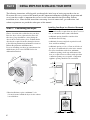 7
7
-
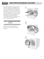 8
8
-
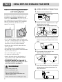 9
9
-
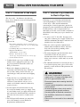 10
10
-
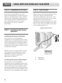 11
11
-
 12
12
-
 13
13
-
 14
14
-
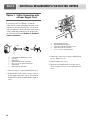 15
15
-
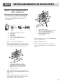 16
16
-
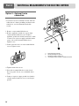 17
17
-
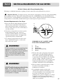 18
18
-
 19
19
-
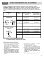 20
20
-
 21
21
-
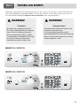 22
22
-
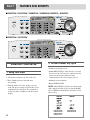 23
23
-
 24
24
-
 25
25
-
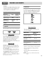 26
26
-
 27
27
-
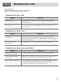 28
28
-
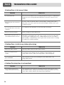 29
29
-
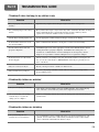 30
30
-
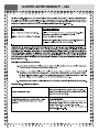 31
31
-
 32
32
-
 33
33
-
 34
34
-
 35
35
-
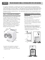 36
36
-
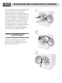 37
37
-
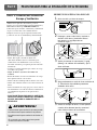 38
38
-
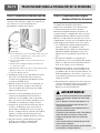 39
39
-
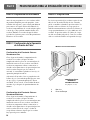 40
40
-
 41
41
-
 42
42
-
 43
43
-
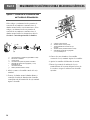 44
44
-
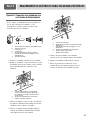 45
45
-
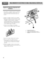 46
46
-
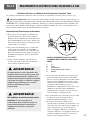 47
47
-
 48
48
-
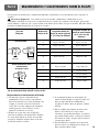 49
49
-
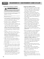 50
50
-
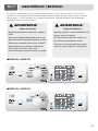 51
51
-
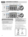 52
52
-
 53
53
-
 54
54
-
 55
55
-
 56
56
-
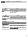 57
57
-
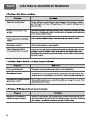 58
58
-
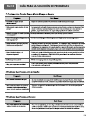 59
59
-
 60
60


Ag Leader DLE0332W El manual del propietario
- Categoría
- Secadoras de ropa eléctricas
- Tipo
- El manual del propietario
En otros idiomas
- English: Ag Leader DLE0332W Owner's manual
Otros documentos
-
LG Electronics DLE3733S Manual de usuario
-
LG TDD16515 El manual del propietario
-
LG TD-V12066G El manual del propietario
-
LG Electronics DLE0442W Manual de usuario
-
-
LG TDW15116G El manual del propietario
-
LG TD-V10056G El manual del propietario
-
LG TD-V10056E El manual del propietario
-
LG TD-V10050G Manual de usuario
-
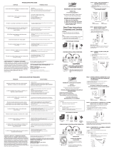 DrySafer DS17LAM Guía de instalación
