NuTone CFC56BR Manual de usuario
- Categoría
- Ventiladores domésticos
- Tipo
- Manual de usuario
Este manual también es adecuado para

MODELS CFC56BR • CFC56WH
Page 1
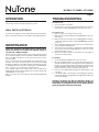
READ AND SAVE THESE INSTRUCTIONS
COMMERCIAL
CEILING FANS
WARNING
TO REDUCE THE RISK OF FIRE, ELECTRICAL SHOCK, OR INJURY
TO PERSONS, OBSERVE THE FOLLOWING:
1. Use this unit only in the manner intended by the manufacturer. If
you have questions, contact the manufacturer at the address or
telephone number listed in the warranty.
2. Before servicing or cleaning unit, or installing a light kit, switch power
off at service panel and lock service panel to prevent power from
being switched on accidentally. When the service disconnecting
means cannot be locked, securely fasten a prominent warning
device, such as a tag, to the service panel.
3. Installation work and electrical wiring must be done by a qualified
person(s) in accordance with all applicable codes and standards,
including fire-rated construction codes and standards.
4. When cutting or drilling into wall or ceiling, do not damage electrical
wiring and other hidden utilities.
5. This unit must be grounded.
6. Do not use this fan with any solid-state fan speed control device.
7. Most outlet boxes commonly used for the support of lighting fixtures
are not acceptable for fan support and may need to be replaced,
consult a qualified electrician if in doubt.
Use only UL Listed outlet boxes marked “FOR FAN SUPPORT”.
The outlet box and support structure must be securely mounted and
capable of reliably supporting a minimum of 50 pounds. Use only
the two steel
screws (and lock washers) provided with the outlet box
for
mounting the ceiling fan to the outlet box The outlet box must
not twist or work loose. DO NOT USE PLASTIC OUTLET BOXES.
8. After marking electrical connections, spliced conductors should
be turned upward and pushed carefully up into outlet box. The
wires should be spread apart with the grounded conductor and the
equipment-grounding conductor on one side of the outlet box.
9. After installation is complete, make sure that all connections are
secure to prevent the fan from falling. Make sure all wire connections
are secure, and that there are no exposed conductor strands.
10. Do not use water or detergents when cleaning the fan or fan blades.
A dry dust cloth or lightly dampened cloth will be suitable for most
cleaning.
CAUTION
TO REDUCE THE RISK OF PERSONAL INJURY, OBSERVE THE
FOLLOWING:
1. To avoid motor bearing damage and noisy and/or unbalanced
impellers, keep drywall spray, construction dust, etc. off power unit.
2. The fan must be mounted with a minimum of 10 feet clearance
between fan blades and floor.
3. Make sure that your installation will not allow the fan to come into
contact with any adjacent obstacles such as doors, hanging lamps,
etc.
4. If you are installing more than one ceiling fan, do not mix the blade
sets.
5. Do not bend the blade brackets.
6. Do not insert objects in between rotating fan blades.
7. Be careful when working around or cleaning the fan.
8. Please read specification label on product for further information
and requirements.
WEIGHT OF FAN
The weight of your fan is 17.9 lbs. The weights of light kits, down rods,
and ceiling adapters are listed in the instructions packed with those
accessories.
INSTALLER:
Leave this manual with the
homeowner.
HOMEOWNER:
Use and care instructions on
page 6.

MODELS CFC56BR • CFC56WH
Page 2
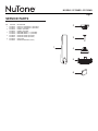
CONTENTS
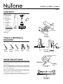
Unpack your fan and
check the contents.
You should have the
following items:
A - Blade Set (3)
B - Hanger Bracket
Assembly
C - 6” Downrod
D - Coupling Cover
E - Fan Motor
Assembly
F - Package Hardware:
Mounting Hardware
2 screws, 2 wood
screws, 2 washers,
4 lock washers,
3 wire nuts
Balance Kit
TOOLS & MATERIALS
REQUIRED
PHILLIPS
SCREW
DRIVER
FLAT
BLADE
SCREW
DRIVER
11mm
WRENCH
STEP
LADDER
WIRE
CUTTER
A
B
C
D
E
F
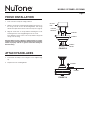
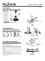
MOUNTING OPTIONS
If there isn’t an existing UL listed mounting box, then read the following
instructions. Disconnect the power by removing fuses or turning off
circuit breakers.
Secure the outlet box directly to the building structure. Use appropriate
fasteners and building materials. The outlet box and its support must be
able to fully support the moving weight of the fan (at least 50 lbs). Do
not use plastic outlet boxes.
Figures 1,2 and 3 are examples of different ways to mount the outlet box.
Note: You may need a longer downrod to maintain proper blade clearance
when installing on a steep, sloped ceiling. (Fig. 3)
To hang your fan where there is an existing fixture but no ceiling joist,
you may need an installation hanger bar as shown in Figure 4.
OUTLET BOX
PROVIDE STRONG
SUPPORT
RECESSED
OUTLET BOX
CEILING
MOUNTING
PLATE
OUTLET BOX
FIGURE 1
FIGURE 3
FIGURE 4
OUTLET BOX
FIGURE 2

MODELS CFC56BR • CFC56WH
Page 3
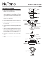
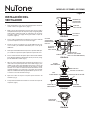
INSTALL THE FAN
1. Remove the decorative canopy bottom cover from the canopy by
turning the cover counter clockwise. (Fig. 5)
2. Remove the hanger bracket from the canopy by removing the 1 of
2 screws from the bottom of the hanger bracket and loosening the
other one a half turn from the screw head. Next, turn the canopy
counter clockwise to removing the hanger bracket from the canopy.
(Figure 5)
3. Pass the 120-volt supply wires through the center hole in the ceiling
hanger bracket as shown in Fig. 6.
4. Secure the hanger bracket to the ceiling outlet box with the screws
and washers provided with your outlet box.
5. Remove the hanger pin, locking pin and set screws from the top of
the motor assembly.
6. Route wires exiting from the top of the fan motor through the couping
cover, canopy cover and canopy, then through the ball / downrod.
(Fig. 7)
7. Align the holes at the bottom of the downrod with the holes in the
collar on top of the motor housing (Fig.7). Carefully insert the hanger
pin through the holes in the collar and downrod. Be careful not to
jam the pin against the wiring inside the downrod. Insert the locking
pin through the hole near the
end
of the hanger pin until it snaps
into its locked position, as noted in the circle inset of Fig. 7.
8. Tighten two set screws on top of the fan motor firmly.
(Fig. 7)
9. Place the downrod ball into the hanger bracket socket.
(Fig. 8)
FIGURE 8
REGISTRATION
SLOT
FIGURE 5
CEILING
HANGER
BRACKET
CEILING
CANOPY
CANOPY
COVER
MOUNTING SCREWS
(SUPPLIED WITH
ELECTRICAL BOX)
HOOK
CEILING
MOUNTING
PLATE
CUL LISTED
ELECTRIAL
BOX
FIGURE 6
FIGURE 7
120V WIRES
WASHERS
DOWNROD
CANOPY
SET SCREWS
LOCKING
PIN
HANGER PIN
CANOPY COVER
COUPLING
COVER

MODELS CFC56BR • CFC56WH
Page 4
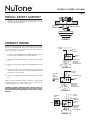
INSTALL SAFETY SUPPORT
1. An additional safety support is provided to prevent the fan from
falling. Secure the safety cable to the ceiling joist with screw and
washer, as illustrated in Figure 9.
HANGER
BRACKET
SAFETY CABLE
FIGURE 9
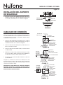
CONNECT WIRING
Remember to disconnect the power. Follow the steps below to connect
the fan to your building/facility wiring. Use the wire nuts supplied with
your fan. Secure the connectors with electrical tape. Make sure there
are no loose strands or connections.
1. Connect the fan supply (black) wire and light supply (blue) wire to
the black household supply wire as shown in Figure 10.
2. Connect the neutral fan (white) wire to the white neutral household
wire.
3. Connect the fan ground wire (green) to the building/facility ground
wire.
4. After connecting the wires, spread them apart so that the green and
white wires are on one side of the outlet box and the black and the
blue wires are on the other side.
5. Turn the connecting nuts upward and push the wiring into the outlet
box.
Figures 11 and 12 illustrate the wiring connections for optional wall
control (The wire color out of wall control may vary, see wall control’s
installation manual for correct wire connections.)
WARNING: TO REDUCE THE RISK OF FIRE, ELECTRIC SHOCK, OR
OTHER PERSONAL INJURY, MOUNT FAN ONLY ON AN OUTLET
BOX OR SUPPORTING SYSTEM MARKED ACCEPTABLE FOR FAN
SUPPORT.
FIGURE 12
GROUND TO
MOUNTING
BRACKET
OR DOWNROD
120 VAC
LINE IN
GREEN
GROUND
WIRING
BOX
HW
EULB
KLB
KLB
WH
FAN
LIGHT
FAN
WIRING
BOX
GROUND TO
MOUNTING
BRACKET
OR DOWNROD
WH
WH
FAN
LIGHT
SWITCH
GREEN GROUND
FIGURE 11
BLUE
BLK
BLK
FIGURE 10
WH
WH
GRN
WIRING
BOX
GROUND TO
MOUNTING
BRACKET
OR DOWNROD
FAN
GREEN
GROUND
BLK BLK
BLUE
120 VAC
LINE IN
120 VAC
LINE IN
OPTIONAL
WALL
CONTROL
OPTIONAL
WALL
CONTROL

MODELS CFC56BR • CFC56WH
Page 5
FINISH INSTALLATION
1. Tuck connections neatly into ceiling outlet box.
2. Slide the canopy up to mounting bracket and place the key hole on
the canopy over the screw on the mounting bracket, turn canopy
until it locks in place at the narrow section of the key holes. (Fig. 13)
3. Align the circular hole on canopy with the remaining hole on the
mounting bracket, secure by tightening the two set screws.
Note: Adjust the canopy screws as necessary until the canopy and
canopy cover are snug.
Warning: Make sure tab at bottom of hanger bracket is properly
seated in groove of hanger ball before attaching canopy to bracket.
Failure to properly seat tab in groove could cause damage to
electrical wiring.
ATTACH FAN BLADES
1. Fasten blade assembly to motor using the screws supplied. (Fig.
14)
2. Repeat for the two remaining blades.
FIGURE 13
OUTLET
BOX
HANGER
BRACKET
CANOPY
CANOPY
COVER
SCREWS
FIGURE 14
SCREWS
BLADES

MODELS CFC56BR • CFC56WH
Page 6
OPERATION
Turn on the power and check the operation of your fan.
WALL SWITCH (OPTIONAL)
Your fan is also designed to operate with a wall switch (sold separately).
Refer to wall switch instructions for installation and wiring information.
MAINTENANCE
IMPORTANT: MAKE SURE THE POWER IS OFF AT THE ELECTRICAL
PANEL BOX BEFORE YOU ATTEMPT ANY REPAIRS. REFER TO
THE SECTION “CONNECT WIRING”.
Because of the fan’s natural movement, some connections may become
loose. Check the support connections, brackets, and blade attachments
twice a year. Make sure they are secure. (It is not necessary to remove
fan from ceiling.)
Clean your fan periodically to help maintain its new appearance over
the years. Use only a soft brush or lint-free cloth to avoid scratching
the finish. The plating is sealed with a lacquer to minimize discoloration
or tarnishing. Do not use water when cleaning. This could damage the
motor, or the wood, or possibly cause an electrical shock.
You can apply a light coat of furniture polish to the wood blades for
additional protection and enhanced beauty. Cover small scratches with
a light application of shoe polish.
There is no need to oil your fan. The motor has permanently lubricated
bearings.
TROUBLESHOOTING
Fan will not start.
1. Check circuit fuses or breakers.
2. Check line wire connections to the fan and switch wire connections
in the switch housing. CAUTION: Make sure main power is off.
Fan sounds noisy.
1. Make sure all motor housing screws are snug.
2. Make sure the screws that attach the fan blade bracket to the motor
hub is tight.
3. Make sure wire nut connections are not rubbing against each other
or the interior wall of the switch housing. CAUTION: Make sure main
power is off.
4. Allow a 24-hour “breaking-in” period. Most noise associated with a
new fan disappear during this time.
5. Some fan motors are sensitive to signals from solid-state variable
speed controls. If you have installed this type of control, choose and
install another type of control.
6. Make sure the upper canopy is a short distance from the ceiling. It
should not touch the ceiling.
Fan wobbles.
1. Check that all blade and blade arm screws are secure.
2. Most fan wobbling problems are caused when blade levels are
unequal. Check this level by selecting a point on the ceiling above
the tip of one of the blades. Measure this distance. Rotate the fan
until the next blade is positioned for measurement. Repeat for each
blade. The distance deviation should be equal within 1/8”.
3. Use the enclosed Blade Balancing Kit if the blade wobble is still
noticeable.
4. If the blade wobble is still noticeable, interchanging two adjacent
(side by side) blades can redistribute the weight and possibly result
in smoother operation.
WARNING: TO REDUCE THE RISK OF PERSONAL INJURY, DO
NOT BEND THE BLADE ARM WHILE INSTALLING, BALANCING
THE BLADES, OR CLEANING THE FAN. DO NOT INSERT FOREIGN
OBJECTS BETWEEN ROTATING FAN BLADES.

MODELS CFC56BR • CFC56WH
Page 7
1
2
3
4
5
6
SERVICE PARTS
KEY PART NO. DESCRIPTION
1 S77000972 BLADE SET (CONTAINS 3) (CFC52WH)
S77000973 BLADE SET (CONTAINS 3) (CFC52BR)
2 S77000974 CANOPY (CFC52WH)
S77000975 CANOPY (CFC52BR)
3 S77000979 DOWNROD W/BALL, 6” (CFC52WH)
S77000980 DOWNROD W/BALL, 6” (CFC52BR)
4 S77000976 COUPLING COVER (CFC52WH)
S77000977 COUPLING COVER (CFC52BR)
6 S77000978 PARTS BAG
* S77000981 MOUNTING BRACKET (CFC52)

MODELS CFC56BR • CFC56WH
Page 8
WARRANTY
NuTone Ceiling Fans and Accessories
Limited Warranty
WARRANTY PERIOD: NuTone warrants to the original consumer purchaser of its NuTone Ceiling Fans and Accessories will be
materially free from defects in materials or workmanship for a period of one (1) year from the date of original purchase. This warranty
does not cover glass globes or light bulbs provided with the light kits.
The limited warranty period for replacement parts, and for fans repaired or replaced under this limited warranty, shall continue for the
remainder of the original warranty period.
NO OTHER WARRANTIES: THE FOREGOING WARRANTIES ARE EXCLUSIVE AND IN LIEU OF ANY OTHER WARRANTIES,
EXPRESS OR IMPLIED. NUTONE DISCLAIMS AND EXCLUDES ALL OTHER EXPRESS WARRANTIES, AND DISCLAIMS
AND EXCLUDES ALL WARRANTIES IMPLIED BY LAW, INCLUDING WITHOUT LIMITATION THOSE OF MERCHANTABILITY
AND FITNESS FOR A PARTICULAR PURPOSE. TO THE EXTENT THAT APPLICABLE LAW PROHIBITS THE EXCLUSION OF
IMPLIED WARRANTIES, THE DURATION OF ANY APPLICABLE IMPLIED WARRANTY IS LIMITED TO THE PERIOD SPECIFIED
FOR THE EXPRESS WARRANTY. Some states do not allow limitations on how long an implied warranty lasts, so the above
limitation may not apply to you. Any oral or written description of the fan is for the sole purpose of identifying it and shall not be
construed as an express warranty.
REMEDY: During the applicable limited warranty period, NuTone will, at its option, provide replacement parts for, or repair or replace,
without charge, any fan or part, to the extent NuTone finds it to be covered by and in breach of this limited warranty. NuTone will ship
the repaired or replaced fan or replacement parts to you at no charge. You are responsible for all costs for removal, reinstallation and
shipping, insur
ance or other freight charges incurred in the shipment of the fan or part to NuTone. This warranty does not cover (a)
normal maintenance and service, (b) normal wear and tear, (c)any fans or parts which have been subject to misuse, abuse, abnormal
usage, negligence, accident, improper or insufficient maintenance, storage or repair (other than repair by NuTone), (d) damage
caused by faulty installation, or installation or use contrary to recommendations or instructions, (e) any fan that has been moved from
its original point of installation, (f)damage caused by environmental or natural elements, (g)damage in transit, (h)natural wear of
finish, (i)fans in commercial or nonresidential use, or (j)damage caused by fire, flood or other act of God. This warranty covers only
fans sold in the United States or through U.S. distributors authorized by NuTone.
EXCLUSION OF DAMAGES: NUTONE’S OBLIGATION TO PROVIDE REPLACEMENT PARTS, OR REPAIR OR REPLACE, AT
NUTONE’S OPTION, SHALL BE YOUR SOLE AND EXCLUSIVE REMEDY UNDER THIS LIMITED WARRANTY AND NUTONE’S
SOLE AND EXCLUSIVE OBLIGATION. NUTONE SHALL NOT BE LIABLE FOR INCIDENTAL, INDIRECT, CONSEQUENTIAL
OR SPECIAL DAMAGES ARISING OUT OF OR IN CONNECTION WITH THE FAN, ITS USE OR PERFORMANCE. Incidental
damages include but are not limited to such damages as loss of time and loss of use. Consequential damages include but are not
limited to the cost of repairing or replacing other property which was damaged if the fan does not work properly.
Some states do not allow the exclusion or limitation of incidental or consequential damages, so the above limitation or exclusion
m
ay
not apply to you. This warranty gives you specific legal rights, and you may also have other rights, which vary from state to state.
This warranty supersedes all prior warranties and is not transferable from the original consumer purchaser.
NUTONE SHALL NOT BE LIABLE TO YOU, OR TO ANYONE CLAIMING UNDER YOU, FOR ANY OTHER OBLIGATIONS OR
LIABILITIES, INCLUDING, BUT NOT LIMITED TO, OBLIGATIONS OR LIABILITIES ARISING OUT OF BREACH OF CONTRACT
OR WARRANTY, NEGLIGENCE OR OTHER TORT OR ANY THEORY OF STRICT LIABILITY, WITH RESPECT TO THE FAN OR
NUTONE’S ACTS OR OMISSIONS OR OTHERWISE.
This warranty covers only replacement or repair of defective fans or parts at NuTone’s main facility and does not include the cost of
field service travel and living expenses.
Any assistance NuTone provides to or procures for you outside the terms, limitations or exclusions of this limited warranty will not
constitute a waiver of such terms, limitations or exclusions, nor will such assistance extend or revive the warranty.
NuTone will not reimburse you for any expenses incurred by you in repairing or replacing any defective Fan, except for those incurred
with NuTone’s prior written permission.
HOW TO OBTAIN WARRANTY SERVICE: To qualify for warranty service, you must (a) notify NuTone at the address or telephone
number stated below within seven (7)days of discovering the covered defect, (b) give the model number and part identification and
(c)describe the nature of any defect in the fan or part. At the time of requesting warranty service, you must present evidence of the
original purchase date.
Broan-NuTone LLC,
926 W
est State Street, Hartford, WI 53027 (888-336-6151)
If you must send the fan or part to NuTone, as instructed by NuTone, you must properly pack the fan or part—NuTone is not
responsible for damage in transit.
79040061A

MODELOS CFC56BR • CFC56WH
Página 9
LEA Y GUARDE ESTAS INSTRUCCIONES
VENTILADORES DE
TECHO COMERCIALES
ADVERTENCIA
PARA REDUCIR EL RIESGO DE INCENDIO, DESCARGA ELÉCTRICA
O LESIONES, SIGA LAS INDICACIONES QUE SE ENUMERAN A
CONTINUACIÓN:
1. Utilice esta unidad sólo de la forma indicada por el fabricante. Si desea
realizar consultas, comuníquese con el fabricante a la dirección o al
número de teléfono que aparece en la garantía.
2. Antes de realizar tareas de mantenimiento o limpiar la unidad o instalar
un kit de iluminación, apague el interruptor de electricidad desde
el panel de servicio y bloquee el panel de servicio para evitar que
alguien conecte la electricidad por accidente. Cuando el sistema de
desconexión de servicio no se pueda bloquear, coloque en el panel
de servicio un elemento de advertencia que se destaque como, por
ejemplo, una etiqueta.
3. El trabajo de instalación y cableado eléctrico deberá hacerlo una
persona calificada conforme a todos los códigos y estándares vigentes,
incluidos los códigos y los estándares de clasificación ignífuga para
construcciones.
4. Al cortar o perforar en una pared o techo, no dañe el cableado eléctrico
ni otros servicios no visibles.
5. Esta unidad debe estar conectada a tierra.
6. No utilice este ventilador con ningún dispositivo de control de velocidad
de ventiladores con semiconductores.
7. La mayoría de las cajas de distribución utilizadas para aparatos de
luz no son admisibles para ventiladores y probablemente deban ser
reemplazadas. En caso de duda, consulte a
un
electricista calificado.
Sólo utilice cajas de distribución homologadas por UL y que indiquen
"FOR FAN SUPPORT" (Para ventiladores). La caja de distribución
y la estructura de soporte deben quedar firmemente instaladas y
deben soportar un peso mínimo de 50 libras (22.7 kg). Sólo utilice los
dos tornillos de acero (y las arandelas de seguridad) incluidos con la
caja de distribución para instalar el ventilador de techo a la caja de
distribución. La caja de distribución no debe quedar torcida ni suelta
al estar en funcionamiento. NO UTILICE CAJAS DE DISTRIBUCIÓN
DE PLÁSTICO.
8. Después de realizar las conexiones eléctricas, debe girar los
conductores empalmados hacia arriba e introducirlos con cuidado en
la caja de distribución. Deberá separar los cables con el conductor a
tierra y el conductor de conexión a tierra del equipo a un costado de la
caja de distribución.
9. Después de terminar la instalación, asegúrese de que todas las
conexiones queden bien sujetas para evitar que el ventilador se caiga.
Asegúrese de que todas las conexiones de los cables estén firmemente
sujetas y que no haya hilos conductores expuestos.
10. No use agua ni detergentes al limpiar el ventilador o las paletas del
ventilador. Para la limpieza, un trapo seco
o ligeramente
humedecido
será suficiente.
PRECAUCIÓN
PARA REDUCIR EL RIESGO DE LESIONES, SIGA LAS INDICACIONES
QUE SE ENUMERAN A CONTINUACIÓN:
1. Para evitar daños a los cojinetes del motor e impulsores ruidosos y/o
desnivelados, mantenga la unidad de alimentación eléctrica protegida
del rocío de yeso, el polvo de construcción, etc.
2. El ventilador debe quedar instalado con un espacio mínimo de 10 pies
(3 metros) entre las paletas del ventilador y el piso.
3. Al instalar el ventilador, asegúrese de que no quede en contacto con
otros obstáculos adyacentes como puertas, lámparas colgantes, etc.
4. Si va a instalar más de un ventilador de techo, no mezcle los juegos de
paletas.
5. No doble los soportes de las paletas.
6. No inserte objetos entre las paletas del ventilador mientras estén
rotando.
7. Tenga cuidado al trabajar alrededor del ventilador o al limpiarlo.
8. Lea la etiqueta de especificaciones del producto para obtener más
información y requisitos.
PESO DEL VENTILADOR
El peso de su ventilador es de 17.9 libras (8.12 kg). Los pesos de los kits
de iluminación, las barras descendentes y los adaptadores de techo se
encuentran en las instrucciones incluidas con dichos accesorios.
INSTALADOR:
Deje este manual con el
propietario.
PROPIETARIO:
Instrucciones de utilización y
cuidados en la página 14.

MODELOS CFC56BR • CFC56WH
Página 10
A
B
C
D
E
F
HERRAMIENTAS Y
MATERIALES REQUERIDOS
DESTOR-
NILLADOR
PHILLIPS
DESTOR-
NILLADOR
PLANO
LLAVE
DE 11 mm
ESCALERA
DE TIJERA
ALICATE PARA
CORTAR ALAMBRE
OPCIONES DE MONTAJE
Si no hay una caja de montaje homologada por UL, entonces lea las
siguientes instrucciones: Desconecte la corriente eléctrica retirando los
fusibles o apagando los disyuntores.
Sujete la caja de distribución directamente a la estructura del edificio. Utilice
las abrazaderas y los materiales de armado correspondientes. La caja de
distribución y su soporte deben soportar el peso total del ventilador en
movimiento (por lo menos 50 libras/22 kg). No utilice cajas de distribución
de plástico.
Las figuras 1, 2 y 3 son ejemplos de las distintas formas de instalar la caja
de distribución.
Nota: Probablemente necesite una barra descendente más larga para
mantener el espacio adecuado de las paletas al instalar el ventilador en un
techo empinado, en declive. (Fig. 3)
Para colgar el ventilador donde haya un aparato de luz existente pero no
haya una viga de techo, necesitará instalar una barra de suspensión como
se muestra en la figura 4.
CAJA DE DISTRIBUCIÓN
PROPORCIONA UN
SOPORTE FUERTE
CAJA DE
DISTRIBUCIÓN
EMPOTRADA
PLACA DE
MONTAJE PARA
TECHO
CAJA DE DISTRIBUCIÓN
FIGURA 1
FIGURA 3
FIGURA 4
CAJA DE DISTRIBUCIÓN
FIGURA 2
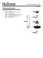
CONTENIDO
Desempaque su
ventilador y verifique
que el contenido esté
completo. El paquete
debe incluir lo siguiente:
A - Juego de paletas
de doble faz (5)
B - Conjunto de soportes
de suspensión
C - Barra descendente
D - Tapa acopladora
E - Conjunto del motor
del ventilador
F - Paquete del equipo:
Herrajes de montaje
2 tornillos, 2 tornillos para madera, 2 arandelas,
4arandelas de seguridad, 3 tuercas para alambre
Kit de nivelación

MODELOS CFC56BR • CFC56WH
Página 11
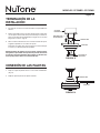
INSTALACIÓN DEL
VENTILADOR
1. Retire la tapa inferior de la carcasa decorativa girando la cubierta en
sentido contrario a las agujas del reloj. (Fig. 5)
2. Quite el soporte de suspensión de la carcasa, retire 1 de los 2 tornillos
de la parte inferior del soporte de suspensión y afloje el segundo girando
media vuelta la cabeza del tornillo. A continuación, gire la carcasa
en sentido contrario a las agujas del reloj para retirar el soporte de
suspensión. (Figura 5)
3. Pase los cables de alimentación de 120 voltios por el orificio central del
soporte de suspensión, tal como se muestra en la fig. 6.
4. Asegure el soporte de suspensión a la caja de distribución del techo
con los tornillos y las arandelas suministrados junto con la caja de
distribución.
5. Retire el pivote de la abrazadera de suspensión, el pasador de bloqueo
y los tornillos de sujeción de la parte superior del conjunto del motor.
6. Pase los cables existentes de la parte superior del motor del ventilador
por la cubierta acopladora, la cubierta de la carcasa y la carcasa, y luego
por la bola/barra descendente. (Fig. 7)
7. Alinee los orificios de la parte inferior de la barra descendente con los
orificios del aro en la parte superior de
la
carcasa del motor (fig. 7). Con
cuidado inserte el pivote de la abrazadera a través de los orificios del
aro y de la barra descendente. Asegúrese de que el pivote no quede
atascado con los cables en el interior de la barra descendente. Inserte
el pasador de bloqueo en el orificio que se encuentra casi en la punta
del pivote de la abrazadera hasta que quede trabado en posición, como
se observa en el círculo insertado de la fig. 7.
8. Ajuste dos tornillos de sujeción en la parte superior del motor del
ventilador. (Fig. 7)
9. Coloque la bola de la barra descendente en el encastre del soporte de
suspensión. (Fig. 8)
FIGURA 8
RANURA DE
REGISTRO
FIGURA 5
SOPORTE DE
SUSPENSIÓN
PARA TECHO
CARCASA
PARA TECHO
TAPA DE LA
CARCASA
TORNILLOS DE
MONTAJE (INCLUIDOS
CON CAJA DE CONEXIONES)
GANCHO
PLACA DE
MONTAJE
PARA TECHO
CAJA DE
CONEXIONES
HOMOLOGADA
POR CUL
FIGURA 6
FIGURA 7
CABLES DE 120V
ARANDELAS
BARRA
DESCENDENTE
CARCASA
TORNILLOS DE SUJECIÓN
PASADOR
DE BLOQUEO
PIVOTE DE LA
ABRAZADERA
TAPA DE LA CARCASA
TAPA
ACOPLADORA

MODELOS CFC56BR • CFC56WH
Página 12
INSTALACIÓN DEL SOPORTE
DE SEGURIDAD
1. Se incluye un soporte de seguridad adicional para evitar que el
ventilador se caiga. Sujete el cable de seguridad a la viga del techo
con un tornillo y una arandela, tal como se muestra en la figura 9.
SOPORTE DE
SUSPENSIÓN
CABLE DE
SEGURIDAD
FIGURA 9
CABLEADO DE CONEXIÓN
Recuerde desconectar la alimentación eléctrica. Siga los pasos que se
indican a continuación para conectar el ventilador a la instalación eléctrica
de su edificio/facilidad. Utilice las tuercas para alambre suministradas con
su ventilador. Sujete los conectores con cinta aislante. Asegúrese de que
no haya hilos ni conexiones sueltos.
1. Conecte el cable de alimentación del ventilador (negro) y el cable de
alimentación de luz (azul) al cable de alimentación de color negro de
su instalación eléctrica, como se muestra en la figura 10.
2. Conecte el cable neutro del ventilador (blanco) al cable neutro de color
blanco de su instalación eléctrica.
3. Conecte el cable a tierra del ventilador (verde) con el cable a tierra de
su edificio/facilidad.
4. Después de conectar los cables, sepárelos de manera que los cables
de color verde y blanco queden a un lado de la caja de distribución y
los cables de color negro y los azules queden del otro lado.
5. Gire las tuercas de conexión hacia arriba e introduzca los cables en la
caja de distribución.
Las figuras 11 y 12 ilustran las conexiones de los cables para un control
de pared opcional (el color de los cables fuera del control de pared podrá
variar, lea el manual de instalación
del
control de pared para conocer las
conexiones correctas de los cables).
ADVERTENCIA: PARA REDUCIR EL RIESGO DE INCENDIO,
DESCARGA ELÉCTRICA O LESIONES, SÓLO INSTALE EL
VENTILADOR EN UNA CAJA DE DISTRIBUCIÓN O EN UN SISTEMA
DE SOPORTE APTO PARA VENTILADOR.
FIGURA 12
CABLE A TIERRA
A SOPORTE DE
MONTAJE O BARRA
DESCENDENTE
ENTRADA DE
LÍNEA 120 VCA
CABLE A
TIERRA VERDE
CAJA DE
CONEXIONES
OCB
AZUL
GEN
GEN
BCO
VENTILADOR
LUZ
VENTI-
LADOR
CAJA DE CONEXIONES
CABLE A TIERRA
A SOPORTE DE
MONTAJE O BARRA
DESCENDENTE
BCO
BCO
VENTILADOR
INTERRUP-
TOR DE LUZ
CABLE A TIERRA VERDE
FIGURA 11
AZUL
NEG
NEG
FIGURA 10
BCO
BCO
VER
CAJA DE
CONEXIONES
CABLE A TIERRA
A SOPORTE DE
MONTAJE O BARRA
DESCENDENTE
VENTILADOR
CABLE A
TIERRA VERDE
NEG NEG
AZUL
ENTRADA DE
LÍNEA 120 VCA
ENTRADA DE
LÍNEA 120 VCA
CONTROL
DE PARED
OPCIONAL
CONTROL
DE PARED
OPCIONAL

MODELOS CFC56BR • CFC56WH
Página 13
TERMINACIÓN DE LA
INSTALACIÓN
1. Introduzca las conexiones de forma ordenada en la caja de distribución
del techo.
2. Deslice hacia arriba la carcasa al soporte de manera que el orificio de la
carcasa quede sobre el tornillo del soporte de montaje. A continuación,
gire la carcasa hasta que quede trabada en su lugar en la sección más
angosta de los orificios. (Fig. 13)
3. Alinee el orificio circular de la carcasa con el orificio restante del soporte,
asegúrelos apretando los dos tornillos de sujeción.
Nota: Ajuste los tornillos de la carcasa según sea necesario hasta que
la carcasa y su cubierta queden bien ajustadas.
Advertencia: Antes de sujetar la carcasa al soporte, asegúrese de que
la lengüeta en la parte inferior del soporte de suspensión calce bien en
la ranura de la bola de la abrazadera. Si la lengüeta no calza bien en la
ranura podría producir daños a la instalación eléctrica.
CONEXIÓN DE LAS PALETAS
1. Sujete el conjunto de paletas al motor con los tornillos suministrados.
(Fig. 14)
2. Repita la operación para las dos paletas restantes.
FIGURA 13
CAJA DE
DISTRIBUCIÓN
SOPORTE DE
SUSPENSIÓN
CARCASA
TAPA DE LA
CARCASA
TORNILLOS
FIGURA 14
TORNILLOS
PALETAS

MODELOS CFC56BR • CFC56WH
Página 14
FUNCIONAMIENTO
Encienda la alimentación y verifique el funcionamiento de su ventilador.
INTERRUPTOR DE PARED (OPCIONAL)
Su ventilador también está diseñado para funcionar con un interruptor de
pared (vendido por separado). Consulte las instrucciones del interruptor de
pared para su instalación y la información de cableado.
MANTENIMIENTO
IMPORTANTE: ANTES DE INTENTAR HACER ALGUNA REPARACIÓN,
ASEGÚRESE DE QUE LA ALIMENTACIÓN ELÉCTRICA ESTÉ
APAGADA EN LA CAJA DEL TABLERO DE ELECTRICIDAD.
CONSULTE LA SECCIÓN “CABLEADO DE CONEXIÓN”.
Debido al movimiento natural del ventilador, es probable que algunas
conexiones se aflojen. Verifique las conexiones de sostén, los soportes y
las sujeciones de las paletas dos veces al año. Asegúrese de que estén
bien sujetas. (No es necesario retirar el ventilador del techo).
Limpie el ventilador de forma periódica para que se mantenga como nuevo
con el paso de los años. Sólo utilice un cepillo suave o un trapo sin hilachos
para no rayar el acabado. El recubrimiento está sellado con laca para
minimizar la decoloración o el cambio de color. No utilice agua para limpiarlo.
Esto podría dañar el motor o la madera o producir una descarga eléctrica.
Puede aplicar una ligera capa de lustramuebles a las paletas de madera
para protegerlas y aumentar su belleza. Cubra los pequeños rayones con
una ligera aplicación de lustre para zapatos.
No hay necesidad de engrasar el ventilador. El motor tienen cojinetes
lubricados permanentemente.
SOLUCIÓN DE PROBLEMAS
El ventilador no se enciende.
1. Verifique los fusibles o los disyuntores.
2. Verifique las conexiones de los cables al ventilador y las conexiones
del cable del interruptor en la carcasa de interruptores. PRECAUCIÓN:
Asegúrese de que el interruptor principal de alimentación esté apagado.
El ventilador hace mucho ruido.
1. Asegúrese de que todos los tornillos de la carcasa del motor estén bien
ajustados.
2. Asegúrese de que los tornillos que sujetan los soportes de las paletas
al cubo del motor estén bien ajustados.
3. Asegúrese de que no haya fricción entre las conexiones de las tuercas
para alambres o con la pared interior de la carcasa de interruptores.
PRECAUCIÓN: Asegúrese de que el interruptor principal de
alimentación esté apagado.
4. Deje pasar un periodo de 24 horas de “adaptación”. La mayoría de los
ruidos de un ventilador nuevo desaparecen con el tiempo.
5. Los motores de algunos ventiladores son sensibles a las señales de
dispositivos de control de velocidad variable con semiconductores. Si
ha instalado este tipo de control, elija e instale otro tipo de control.
6. Asegúrese de que la carcasa superior quede a poca distancia del techo.
No debe tocar el techo.
El ventilador se bambolea.
1. Verifique que todas las paletas y los tornillos de los brazos de las paletas
estén bien ajustados.
2. La mayoría de los problemas de bamboleo se debe
a que
las paletas
están desniveladas. Para verificar los niveles, seleccione un punto en
el techo sobre la punta de una de las paletas. Mida esta distancia. Rote
el ventilador hasta que la siguiente paleta quede posicionada en ese
punto para medirla. Repita esta operación con cada una de las paletas.
La desviación de distancia debe ser igual en un radio de 1/8” (0.3 cm).
3. Utilice el kit de nivelación de paletas si el bamboleo de las paletas
continúa.
4. Si aún percibe el bamboleo de las paletas, puede intercambiar dos
paletas adyacentes (lado a lado) para redistribuir el peso y obtener un
funcionamiento más suave.
ADVERTENCIA: PARA REDUCIR EL RIESGO DE LESIONES, NO DOBLE
LOS BRAZOS DE LAS PALETAS AL INSTALARLAS, NIVELARLAS O AL
LIMPIAR EL VENTILADOR. NO INSERTE OBJETOS EXTRAÑOS ENTRE
LAS PALETAS DEL VENTILADOR MIENTRAS ESTÉN ROTANDO.

MODELOS CFC56BR • CFC56WH
Página 15
PIEZAS DE SERVICIO
1
2
3
4
5
6
CLAVE Nº DE PIEZA DESCRIPCIÓN
1 S77000972 JUEGO DE PALETAS (INCLUYE 3) (CFC52WH)
S77000973 JUEGO DE PALETAS (INCLUYE 3) (CFC52BR)
2 S77000974 CARCASA (CFC52WH)
S77000975 CARCASA (CFC52BR)
3 S77000979 BARRA DESCENDENTE CON BOLA DE 6” (CFC52WH)
S77000980 BARRA DESCENDENTE CON BOLA DE 6” (CFC52BR)
4 S77000976 CUBIERTA DE ACOPLAMIENTO (CFC52WH)
S77000977 CUBIERTA DE ACOPLAMIENTO (CFC52BR)
6 S77000978 BOLSA DE PIEZAS
* S77000981 SOPORTE DE MONTAJE

MODELOS CFC56BR • CFC56WH
Página 16
GARANTÍA
Ventiladores de techo y accesorios NuTone
Garantía limitada
PERIODO DE GARANTÍA: NuTone garantiza al consumidor comprador original de sus ventiladores de techo y accesorios NuTone que
estarán libres de defectos en materiales o mano de obra durante un período de un (1) año a partir de la fecha de la compra original. Esta
garantía no cubre los globos de vidrio ni las bombillas incluidos con los juegos de luces.
El periodo de garantía limitada para las piezas de repuesto y para los ventiladores reparados o reemplazados bajo esta garantía limitada
continuará durante el resto del periodo de garantía original.
NO HAY OTRAS GARANTÍAS: LAS GARANTÍAS ANTERIORES SON EXCLUSIVAS Y EN LUGAR DE CUALQUIER OTRA GARANTÍA,
EXPRESA O IMPLÍCITA. NUTONE NIEGA Y EXCLUYE CUALQUIER OTRA GARANTÍA EXPRESA, Y NIEGA Y EXCLUYE TODAS
LAS GARANTÍAS IMPLÍCITAS POR LEY, INCLUYENDO, SIN LIMITACIONES, LAS DE COMERCIALIZACIÓN Y APTITUD PARA
UN PROPÓSITO EN PARTICULAR. HASTA EL GRADO QUE LA LEY APLICABLE PROHÍBA LA EXCLUSIÓN DE GARANTÍAS
LIMITADAS, LA DURACIÓN DE CUALQUIER GARANTÍA IMPLÍCITA APLICABLE ESTÁ LIMITADA AL PERIODO ESPECIFICADO
PARA LA GARANTÍA EXPRESA. Algunos estados no permiten limitaciones en la duración de una garantía implícita, así que la limitación
anterior tal vez no aplique en su caso. Cualquier descripción verbal o escrita del ventilador es para el único propósito de identificarlo y no
deberá considerarse como una garantía expresa.
REMEDIO: Durante el periodo de garantía limitada aplicable, NuTone, a su opción, suministrará piezas de repuesto, o reparará o
reemplazará, sin cargo alguno, cualquier ventilador o pieza, hasta el grado en que NuTone lo encuentre cubierto bajo esta garantía limitada
y en incumplimiento de la misma. NuTone le enviará el ventilador reparado o reemplazado o las piezas de repuesto sin cargo.
Usted es
r
esponsable de todos los costos de retiro, reinstalación y envío, seguro u otros cargos de flete incurridos en el envío del ventilador o la
pieza a NuTone. Esta garantía no cubre (a) mantenimiento y servicio normal, (b) uso y desgaste normal, (c) ventiladores o piezas sujetos a
mal uso, abuso, uso anormal, negligencia, accidente, mantenimiento inadecuado o insuficiente, almacenamiento o reparación (que no sea
reparación por parte de NuTone), (d) daños causados por instalación defectuosa, o bien instalación o uso contrario a las recomendaciones o
instrucciones, (e) cualquier ventilador que se haya movido de su punto de instalación original, (f) daños ocasionados por el medio ambiente
o los elementos naturales, (g) daños en tránsito, (h) desgaste natural del acabado, (i) ventiladores en uso comercial o no residencial, o (j)
daños ocasionados por incendio, inundación u otro caso fortuito. Esta garantía cubre únicamente los ventiladores vendidos en Estados
Unidos o a través de distribuidores de EE.UU. autorizados por NuTone.
EXCLUSIÓN DE DAÑOS: LA OBLIGACIÓN DE NUTONE DE SUMINISTRAR PIEZAS DE REPUESTO, O DE REPARAR O REEMPLAZAR,
A OPCIÓN DE NUTONE, SERÁ SU ÚNICO Y EXCLUSIVO REMEDIO BAJO ESTA GARANTÍA LIMITADA, Y LA ÚNICA Y EXCLUSIVA
OBLIGACIÓN DE NUTONE. NUTONE NO SERÁ RESPONSABLE POR DAÑOS INCIDENTALES, INDIRECTOS, RESULTANTES
O ESPECIALES QUE SURJAN POR EL USO O DESEMPEÑO DEL VENTILADOR, O EN RELACIÓN CON EL MISMO. Los daños
incidentales incluyen, entre otros, daños como la pérdida de tiempo y la pérdida de uso. Los daños resultantes incluyen, entre otros, el costo
de reparar o reemplazar otros bienes que fueran dañados si el ventilador no
funcionar
a adecuadamente.
Algunos estados no permiten la exclusión o limitación de daños incidentales o resultantes, por lo que la limitación antes mencionada podría
no aplicarse a usted. Esta garantía le otorga derechos legales específicos, y usted podría tener otros derechos que varían de un estado a
otro.
Esta garantía sustituye todas las garantías anteriores y no es transferible del comprador consumidor original.
NUTONE NO SERÁ RESPONSABLE ANTE USTED, O ANTE NADIE QUE RECLAME POR USTED, DE NINGUNA OTRA
OBLIGACIÓN O RESPONSABILIDAD QUE INCLUYEN, ENTRE OTRAS, OBLIGACIONES O RESPONSABILIDADES QUE SURJAN
POR INCUMPLIMIENTO DE CONTRATO O GARANTÍA, NEGLIGENCIA U OTRO ACTO ILÍCITO O CUALQUIER TEORÍA DE
RESPONSABILIDAD ESTRICTA, CON RESPECTO AL VENTILADOR O A LOS ACTOS U OMISIONES DE NUTONE O DE CUALQUIER
OTRA ÍNDOLE.
Esta garantía cubre únicamente el reemplazo o la reparación de ventiladores o piezas defectuosas en la planta principal de NuTone, y no
incluye el costo del viaje para el servicio de campo ni los viáticos.
Cualquier asistencia que proporcione o procure NuTone para usted fuera de los términos, limitaciones o exclusiones de esta garantía
limitada no constituirá una renuncia a dichos términos, limitaciones o exclusiones, ni dicha asistencia extenderá o renovará la garantía.
NuTone no le reembolsará ningún gasto en el que usted haya incurrido al reparar o reemplazar cualquier ventilador defectuoso, excepto los
incurridos con el permiso previo por escrito de NuTone.
CÓMO OBTENER EL SERVICIO CUBIERTO POR LA GARANTÍA: Para tener derecho al servicio cubierto por la garantía, usted debe (a)
notificar a NuTone a la dirección o número de teléfono que aparecen abajo en un plazo de siete (7) días después de descubrir
el
defecto
cubierto, (b) proporcionar el número de modelo y la identificación de la pieza y (c) describir la naturaleza de cualquier defecto en el ventilador
o la pieza. En el momento de solicitar el servicio cubierto por la garantía, debe presentar un comprobante de la fecha original de compra.
Broan-NuTone LLC, 926 West State Street, Hartford, WI 53027 (888-336-6151)
Si debe enviar el ventilador o la pieza a NuTone, tal como lo indique NuTone, debe empaquetar adecuadamente el ventilador o la pieza;
NuTone no se hace responsable por los daños en tránsito.
79040061A
-
 1
1
-
 2
2
-
 3
3
-
 4
4
-
 5
5
-
 6
6
-
 7
7
-
 8
8
-
 9
9
-
 10
10
-
 11
11
-
 12
12
-
 13
13
-
 14
14
-
 15
15
-
 16
16


NuTone CFC56BR Manual de usuario
- Categoría
- Ventiladores domésticos
- Tipo
- Manual de usuario
- Este manual también es adecuado para
en otros idiomas
- English: NuTone CFC56BR User manual
Artículos relacionados
-
NuTone CFC56BR Guía de instalación
-
-
NuTone CFO52WB Guía de instalación
-
-
-
-
NuTone PFMB-42BR Manual de usuario
-
-
-