
IO-Link
capacitive sensors
Carlo Gavazzi Industri Over Hadstenvej 40, 8340 Hadsten, Denmark
Instruction manual
Manuel d’instructions
Manuale d’istruzione
Betriebsanleitung
Manual de instrucciones
Brugervejledning
使用手册
CA18CA, CA30CA


Rev.00 - 06.2018 | CA18CA/CA30CA Capacitve sensors with IO-Link interface | © 2018 | CARLO GAVAZZI Industri
3
EN
Table of contents
1. Introduction .........................................................4
1.1 Description ............................................................... 4
1.2 Validity of documentation ..................................................... 4
1.3 Who should use this documentation ............................................. 4
1.4 Use of the product .......................................................... 4
1.5 Safety precautions ......................................................... 4
1.6 Other documents .......................................................... 4
1.7 Acronyms ............................................................... 5
2. Product .............................................................6
2.1 Main features ............................................................. 6
2.2 Identification number ........................................................ 6
2.3 Operating modes .......................................................... 7
2.3.1 SIO mode ............................................................ 7
2.3.2 IO-Link mode .......................................................... 7
2.4 Output Parameters ......................................................... 8
2.4.1. Sensor front .......................................................... 8
2.4.2. Input selector ......................................................... 11
2.4.3. Logic function block .................................................... 11
2.4.4. Timer (Can be set individually for Out1 and Out2) .............................. 13
2.4.5. Output Inverter ....................................................... 16
2.4.6. Output stage mode .................................................... 16
2.5. Teach procedure ......................................................... 17
2.5.1. External Teach (Teach-by-wire) ............................................. 17
2.5.2. Teach from IO-Link Master ............................................... 17
2.6. Sensor Specific adjustable parameters .......................................... 20
2.6.1. Selection of local or remote adjustment ...................................... 20
2.6.2. Process data and variables ............................................... 20
2.6.3. Sensor application setting ................................................ 20
2.6.4. Temperature alarm threshold .............................................. 20
2.6.5. Safe limits ........................................................... 21
2.6.6. Event configuration .................................................... 21
2.6.7. Quality of run QoR .................................................... 21
2.6.8. Quality of Teach QoT ................................................... 22
2.6.9. Filter Scaler .......................................................... 22
2.6.10. LED indication ....................................................... 22
2.7. Diagnostic parameters ..................................................... 23
3. Wiring diagrams .....................................................24
4. Commissioning ......................................................24
5. Operation ..........................................................25
5.1. User interface of CA18CA…IO and CA30CA… IO ................................. 25
6. IODD file and factory setting ............................................26
6.1. IODD file of an IO-Link device ................................................ 26
6.2. Factory settings .......................................................... 26
7. Appendix ..........................................................26
7.1. Acronyms .............................................................. 26
7.2. IO-Link Device Parameters for CA18CA.. and CA30CA.. ............................. 27
7.2.1. Device parameters ..................................................... 27
7.2.2. SSC parameters ...................................................... 28
7.2.3. Output Parameters ..................................................... 29
7.2.4. Sensor specific adjustable parameters ....................................... 30
7.2.5. Diagnostic parameters .................................................. 31
Dimensions ..........................................................212
Mounting ...........................................................212
Detection Stability .....................................................213
Installation Hints ......................................................214
ENGLISH

Rev.00 - 06.2018 | CA18CA/CA30CA Capacitve sensors with IO-Link interface | © 2018 | CARLO GAVAZZI Industri
4
EN
1.1 Description
Carlo Gavazzi capacitive sensors are devices designed and manufactured in accordance with IEC
international standards and are subject to the Low Voltage (2014/35/EU) and Electromagnetic
Compatibility (2014/30/EU) EC directives.
All rights to this document are reserved by Carlo Gavazzi Industri, copies may be made for internal use
only.
Please do not hesitate to make any suggestions for improving this document.
1. Introduction
This manual is a reference guide for Carlo Gavazzi IO-Link capacitive proximity sensors CA18CA…IO
and CA30…IO. It describes how to install, setup and use the product for its intended use.
1.2 Validity of documentation
This manual is valid only for CA18 and CA30 capacitive sensors with IO-Link and until new documentation
is published.
This instruction manual describes the function, operation and installation of the product for its intended use.
1.3 Who should use this documentation
This manual contains important information regarding installation and must be read and completely
understood by specialized personnel dealing with these proximity capacitive sensors.
We highly recommend that you read the manual carefully before installing the sensor. Save the manual for
future use. The Installation manual is intended for qualified technical personnel.
1.4 Use of the product
Capacitive proximity sensors are non-contact devices capable of measuring the position and/or change
of position of any conductive target. They are also capable of measuring thickness or density of non-
conductive materials. Capacitive proximity sensors are used in a wide variety of applications including
plastic moulding processing, feeding systems for chicken or pigs, assembly line testing, filling or emptying
processes of solid or liquid objects.
The CA18CA…IO and CA30CA… sensors are equipped with IO-Link communication. By using an IO-
Link master it is possible to operate and configure these devices.
1.6 Other documents
It is possible to find the datasheet, the IODD file and the IO-Link parameter manual on the Internet at
http://gavazziautomation.com
1.5 Safety precautions
This sensor must not be used in applications where personal safety depends on the function of the sensor (The
sensor is not designed according to the EU Machinery Directive).
Installation and use must be carried out by trained technical personnel with basic electrical installation
knowledge.
The installer is responsible for correct installation according to local safety regulations and must ensure that
a defective sensor will not result in any hazard to people or equipment. If the sensor is defective, it must be
replaced and secured against unauthorised use.

Rev.00 - 06.2018 | CA18CA/CA30CA Capacitve sensors with IO-Link interface | © 2018 | CARLO GAVAZZI Industri
5
EN
1.7 Acronyms
I/O Input/Output
PD Process Data
PLC Programmable Logic Controller
SIO Standard Input Output
SP Setpoints
IODD I/O Device Description
IEC International Electrotechnical Commission
NO Normally Open contact
NC Normally Closed contact
NPN Pull load to ground
PNP Pull load to V+
Push-Pull Pull load to ground or V+
QoR Quality of Run
QoT Quality of Teach
UART Universal Asynchronous Receiver-Transmitter
SO Switching Output
SSC Switching Signal Channel

Rev.00 - 06.2018 | CA18CA/CA30CA Capacitve sensors with IO-Link interface | © 2018 | CARLO GAVAZZI Industri
6
EN
2. Product
2.1 Main features
New IO-Link Carlo Gavazzi 4-wire DC 4th Generation Tripleshield sensors, built to the highest quality
standards, are available in two different housing sizes.
• CA18CA.. PBT M18-cylindrical threaded barrel housing for flush or non-flush installation with 4-pole
M12 connector or 2 metre PVC cable.
• CA30CA.. PBT M30-cylindrical threaded barrel housing for flush or non-flush installation with 4-pole
M12 connector or 2 metre PVC cable.
They can operate in standard I/O mode (SIO), which is the default operation mode. When connected
to an IO-Link master, they automatically switch to IO-Link mode and can be operated and easily
configured remotely.
Thanks to their IO-Link interface, these devices are much more intelligent and feature many additional
configuration options, such as the settable sensing distance and hysteresis, also timer functions of the
output. Advanced functionalities such as the Logic function block and the possibility to convert one
output into an external input makes the sensor highly flexible in solving decentralized sensing tasks.
2.2 Identification number
Code Option Description
C-Sensing principle: Capacitive Sensor
A-Cylindrical housing with threaded barrel
18 M18 housing
30 M30 housing
CSPlastic housing - PBT
AS23 Axial sensing
FFlush installation
NNon-flush installation
08 8 mm sensing distance (for CA18…)
12 12 mm sensing distance (for CA18…)
16 16 mm sensing distance (for CA30…)
25 25 mm sensing distance (for CA30…)
B-Selectable functions: NPN, PNP, Push-Pull, External Input (only pin 2), External
teach input (only pin 2)
P-Selectable: NO or NC
A2 2 metre PVC cable
M1 M12, 4-pole connector
IO -IO-Link version
Additional characters can be used for customized versions.

Rev.00 - 06.2018 | CA18CA/CA30CA Capacitve sensors with IO-Link interface | © 2018 | CARLO GAVAZZI Industri
7
EN
2.3 Operating modes
IO-Link capacitive sensors are provided with two switching outputs (SO) and can operate in two
different modes: SIO mode (standard I/O mode) or IO-Link mode.
2.3.1 SIO mode
When the sensor operates in SIO mode (default), an IO-Link master is not required. The device works
as a standard capacitive sensor, and it can be operated via a fieldbus device or a controller (e.g.
a PLC) when connected to its PNP, NPN or push-pull digital inputs (standard I/O port). One of the
greatest benefits of these capacitive sensors is the possibility to configure them via an IO-Link master
and then, once disconnected, they will keep the last parameter and configuration settings. In this
way it is possible, for example, to configure the outputs of the sensor individually as a PNP, NPN or
push-pull, or to add timer functions such as T-on and T-off delays or logic functions and thereby satisfy
several application requirements with the same sensor.
2.3.2 IO-Link mode
IO-Link is a standardized IO technology that is recognized worldwide as an international standard (IEC
61131-9).
It is today considered to be the “USB interface” for sensors and actuators in the industrial automation
environment.
When the sensor is connected to one IO-Link port, the IO-Link master sends a wakeup request (wake
up pulse) to the sensor, which automatically switches to IO-Link mode: point-to-point bidirectional
communication then starts automatically between the master and the sensor.
IO-Link communication requires only standard 3-wire unshielded cable with a maximum length of 20 m.
1
2 4
3
L+
C/Q
L-
IO-Link
SIO
IO-Link communication takes place with a 24 V pulse modulation, standard UART protocol via the
switching and communication cable (combined switching status and data channel C/Q) PIN 4 or
black wire.
For instance, an M12 4-pin male connector has:
• Positive power supply: pin 1, brown
• Negative power supply: pin 3, blue
• Digital output 1: pin 4, black
• Digital output 2: pin 2, white
The transmission rate of CA18CA…IO or CA30CA…IO, sensors is 38.4 kBaud (COM2).
Once connected to the IO-Link port, the master has remote access to all the parameters of the sensor and
to advanced functionalities, allowing the settings and configuration to be changed during operation,
and enabling diagnostic functions, such as temperature warnings, temperature alarms and process
data.

Rev.00 - 06.2018 | CA18CA/CA30CA Capacitve sensors with IO-Link interface | © 2018 | CARLO GAVAZZI Industri
8
EN
Thanks to IO-Link it is possible to see the manufacturer information and part number (Service Data) of
the device connected, starting from V1.1. Thanks to the data storage feature it is possible to replace
the device and automatically have all the information stored in the old device transferred into the
replacement unit.
Access to internal parameters allows the user to see how the sensor is performing, for example by
reading the internal temperature.
Event Data allows the user to get diagnostic information such as an error, an alarm, a warning or a
communication problem.
There are two different communication types between the sensor and the master and they are
independent of each other:
• Cyclical for process data and value status – this data is exchanged cyclically.
• Acyclical for parameter configuration, identification data, diagnostic information and events
(e.g. error messages or warnings) – this data can be exchanged on request.
2.4 Output Parameters
The sensor measures five different physical values. These values can be independently adjusted and
used as source for the Switching Output 1 or 2; in addition to those an external input can be selected
for SO2. After selecting one of these sources, it is possible to configure the output of the sensor with
an IO-Link master, following the six steps shown in the Switching Output setup below.
Once the sensor has been disconnected from the master, it will switch to the SIO mode and keep the
last configuration setting.
Sensor front Selector
ALogic
A - B Time
delay Output
inverter Sensor
output
One of
1 to 6
AND, OR,
XOR, S-R
divider
ON, OFF
One-shot
N.O., N.C. NPN, PNP,
Push-Pull
Selector
BLogic
A - B Time
delay Output
inverter Sensor
output
One of
1 to 6
AND, OR,
XOR, S-R
divider
ON, OFF
One-shot
N.O., N.C. NPN, PNP,
Push-Pull
EXT-Input
S.P., Two P.
Window,
Adj. Hyst.
1. SSC1
S.P., Two P.
Window,
Adj. Hyst.
2. SSC2
3. Dust 1
4. Dust 2
5. Temp
6. EXT-Input
A
B
A
B
Out 1
Out 2
EXT-
Input
2.4.1. Sensor front
When an object, solid or liquid, approaches the face of the sensor, the capacitance of the detecting
circuit is influenced and the sensor output changes its status.
1 2 3 4 5 6
2.4.1.1. SSC (Switching Signal Channel)
For presence (or absence of presence) detection of an object in front of the face of the sensor, the
following settings are available: SSC1 or SSC2.
The setpoints can be set from 0 to 10.000 units which represent the change of capacitance of
the detecting circuit. The higher the value, the closer the target appears to the sensing face of the
sensor, also a higher dielectric value of the target will increase the value. E.g. a metal target has a
higher dielectric value than a plastic target.
1

Rev.00 - 06.2018 | CA18CA/CA30CA Capacitve sensors with IO-Link interface | © 2018 | CARLO GAVAZZI Industri
9
EN
2.4.1.2. Switchpoint mode:
The Switchpoint mode setting can be used to create more advanced output behaviour. The following
switchpoint modes can be selected for the switching behaviour of SSC1 and SSC2
Disabled
SSC1 or SSC2 can be disabled individually, but this will also disable the output if it is selected
in the input selector (the logic value will always be “0”).
Single point mode
The switching information changes, when the measurement value passes the threshold defined in
setpoint SP1, with rising or falling measurement values, taking into consideration the hysteresis.
Sensor
Sensing distance
ON OFF
SP1
Hysteresis
Two point mode
The switching information changes when the measurement value passes the threshold defined in
setpoint SP1. This change occurs only with rising measurement values. The switching information
also changes when the measurement value passes the threshold defined in setpoint SP2. This
change occurs only with falling measurement values. Hysteresis is not considered in this case.
Sensor
Sensing distance
SP2
Hyst
OFF OFF
ON
SP1
Hyst
window
Window mode
The switching information changes, when the measurement value passes the thresholds defined in
setpoint SP1 and setpoint SP2, with rising or falling measurement values, taking into consideration
the hysteresis.
Sensor
Sensing distance
ON OFF
SP2
Hysteresis
SP1
Example of presence detection - with non-inverted logic
Example of presence detection - with non-inverted logic
Example of presence detection - with non-inverted logic

Rev.00 - 06.2018 | CA18CA/CA30CA Capacitve sensors with IO-Link interface | © 2018 | CARLO GAVAZZI Industri
10
EN
2.4.1.3. Hysteresis Settings
In SSC1 and SSC2 - single point mode and in windows mode the hysteresis can be set between 1
and 100 % of the actual switching value. Standard settings depend on the sensing type:
CA18CAF… 6%
CA18CAN… 15%
CA30CAF… 7%
CA30CAN… 10%
(SP2 + Hysteresis < SP1) & (SP1 + hysteresis < Sensing range upper limit).
Information
An extended hysteresis is generally used to solve vibration or EMC issues in the application.
2.4.1.4. Dust alarm 1 and Dust alarm 2
The safe limit between when the sensing output is switching and the value at which the sensor can
detect safely even with a slightly build up of dust, can be set.
See 2.6.5 Safe limits.
2.4.1.5. Temperature alarm (TA)
The sensor constantly monitors the internal temperature in the front part of the sensor. Using the
temperature alarm setting it is possible to get an alarm from the sensor if temperature thresholds
are exceeded. See §2.6.4
The temperature alarm has two separate values, one for setting maximum temperature and one for
setting minimum temperature.
It is possible to read the temperature of the sensor via the acyclic IO-Link parameter data.
NOTE!
The temperature measured by the sensor will always be higher than the ambient temperature, due
to internal heating.
The difference between ambient temperature and internal temperature is influenced by how the
sensor is installed in the application. If the sensor is installed in a metal bracket the difference will
be lower than if the sensor is mounted in a plastic one.
2.4.1.6. External input
The output 2 (SO2) can be configured as an external input allowing external signals to be fed into
the sensor, this can be from a second sensor or from a PLC or directly from machine output.

Rev.00 - 06.2018 | CA18CA/CA30CA Capacitve sensors with IO-Link interface | © 2018 | CARLO GAVAZZI Industri
11
EN
2
2.4.2. Input selector
This function block allows the user to select any of the signals from the “sensor front” to the Channel
A or B.
Channels A and B: can select from SSC1, SSC2, Dust1, Dust2, Temperature alarm and external input.
Sensor front Selector
ALogic
A - B Time
delay Output
inverter Sensor
output
One of
1 to 6
AND, OR,
XOR, S-R
divider
ON, OFF
One-shot
N.O., N.C. NPN, PNP,
Push-Pull
Selector
BLogic
A - B Time
delay Output
inverter Sensor
output
One of
1 to 6
AND, OR,
XOR, S-R
divider
ON, OFF
One-shot
N.O., N.C. NPN, PNP,
Push-Pull
EXT-Input
S.P., Two P.
Window,
Adj. Hyst.
1. SSC1
S.P., Two P.
Window,
Adj. Hyst.
2. SSC2
3. Dust 1
4. Dust 2
5. Temp
6. EXT-Input
A
B
A
B
Out 1
Out 2
EXT-
Input
Channel A
Channel B
3
2.4.3. Logic function block
In the logic function block a logic functionca be added directly to the selected signals from the input
selector without using a PLC – making decentralised decisions possible.
The logic functions available are: AND, OR, XOR, SR-FF.
Sensor front Selector
ALogic
A - B Time
delay Output
inverter Sensor
output
One of
1 to 6
AND, OR,
XOR, S-R
divider
ON, OFF
One-shot
N.O., N.C. NPN, PNP,
Push-Pull
Selector
BLogic
A - B Time
delay Output
inverter Sensor
output
One of
1 to 6
AND, OR,
XOR, S-R
divider
ON, OFF
One-shot
N.O., N.C. NPN, PNP,
Push-Pull
EXT-Input
S.P., Two P.
Window,
Adj. Hyst.
1. SSC1
S.P., Two P.
Window,
Adj. Hyst.
2. SSC2
3. Dust 1
4. Dust 2
5. Temp
6. EXT-Input
A
B
A
B
Out 1
Out 2
EXT-
Input
Out 1
Out 2
EN

Rev.00 - 06.2018 | CA18CA/CA30CA Capacitve sensors with IO-Link interface | © 2018 | CARLO GAVAZZI Industri
12
EN
OR function
Symbol Truth table
A B Q
0 0 0
0 1 1
1 0 1
1 1 1
Boolean Expression Q = A + B Read as A OR B gives Q
2-input OR Gate
XOR function
Symbol Truth table
A B Q
0 0 0
0 1 1
1 0 1
1 1 0
Boolean Expression Q = A + B A OR B but NOT BOTH gives Q
2-input XOR Gate
+
AND function
Symbol Truth table
A B Q
0 0 0
0 1 0
1 0 0
1 1 1
Boolean Expression Q = A.B Read as A AND B gives Q
2-input AND Gate
2-input OR Gate

Rev.00 - 06.2018 | CA18CA/CA30CA Capacitve sensors with IO-Link interface | © 2018 | CARLO GAVAZZI Industri
13
EN
“Gated SR-FF” function
The function is designed (to: e.g. function) as a filling or emptying function using only two intercon-
nected sensors
Symbol Truth table
A B Q
0 0 0
0 1 X
1 0 X
1 1 1
X – no changes to the output.
2.4.4. Timer (Can be set individually for Out1 and Out2)
The Timer allows the user to introduce different timer functions by editing the 3 timer parameters:
• Timer mode
• Timer scale
• Timer value
Sensor front Selector
ALogic
A - B Time
delay Output
inverter Sensor
output
One of
1 to 6
AND, OR,
XOR, S-R
divider
ON, OFF
One-shot
N.O., N.C. NPN, PNP,
Push-Pull
Selector
BLogic
A - B Time
delay Output
inverter Sensor
output
One of
1 to 6
AND, OR,
XOR, S-R
divider
ON, OFF
One-shot
N.O., N.C. NPN, PNP,
Push-Pull
EXT-Input
S.P., Two P.
Window,
Adj. Hyst.
1. SSC1
S.P., Two P.
Window,
Adj. Hyst.
2. SSC2
3. Dust 1
4. Dust 2
5. Temp
6. EXT-Input
A
B
A
B
Out 1
Out 2
EXT-
Input
Out 1
Out 2
4
2.4.4.1. Timer mode
This selects which type of timer function is introduced on the Switching Output. Any one of the
following is possible:
2.4.4.1.1. Disabled
This option disables the timer function no matter how the timer scale and timer delay is set up.
2.4.4.1.2. Turn On delay (T-on)
The activation of the switching output is generated after the actual sensor actuation as shown in
the figure below.

Rev.00 - 06.2018 | CA18CA/CA30CA Capacitve sensors with IO-Link interface | © 2018 | CARLO GAVAZZI Industri
14
EN
Example with normally open output
Presence of
target
N.O. Ton Ton Ton
Presence of target
2.4.4.1.3. Turn Off delay (T-off)
The deactivation of the switching output is delayed until after to the time of removal of the target
in the front of the sensor, as like shown in the figure below.
Presence of
target
N.O. Toff Toff Toff Toff
Presence of target
2.4.4.1.4. Turn ON and Turn Off delay (T-on and T-off)
When selected, both the T-on and the Toff delays are applied to the generation of the switching
output.
N.O. Ton Ton Ton
Toff Toff
Presence of target
Example with normally open output
Example with normally open output

Rev.00 - 06.2018 | CA18CA/CA30CA Capacitve sensors with IO-Link interface | © 2018 | CARLO GAVAZZI Industri
15
EN
2.4.4.1.5. One shot leading edge
Each time a target is detected in front of the sensor the switching output generates a pulse of
constant length on the leading edge of the detection. See figure below.
Presence of target
2.4.4.1.6. One shot trailing edge
Similar in function to the one shot leading edge mode, but in this mode the switching output is
changed on the trailing edge of the activation as shown in the figure below.
Example with normally open output
Presence of target
Example with normally open output
2.4.4.1.7. Timer scale
The parameter defines if the delay specified in the Timer delay should be in milliseconds, seconds
or minutes
2.4.4.1.8. Timer Value
The parameter defines the actual duration of the delay. The delay can be set to any integer value
between 1 and 32 767

Rev.00 - 06.2018 | CA18CA/CA30CA Capacitve sensors with IO-Link interface | © 2018 | CARLO GAVAZZI Industri
16
EN
2.4.5. Output Inverter
This function allows the user to invert the operation of the switching output between Normally Open
and Normally Closed.
Sensor front Selector
ALogic
A - B Time
delay Output
inverter Sensor
output
One of
1 to 6
AND, OR,
XOR, S-R
divider
ON, OFF
One-shot
N.O., N.C. NPN, PNP,
Push-Pull
Selector
BLogic
A - B Time
delay Output
inverter Sensor
output
One of
1 to 6
AND, OR,
XOR, S-R
divider
ON, OFF
One-shot
N.O., N.C. NPN, PNP,
Push-Pull
EXT-Input
S.P., Two P.
Window,
Adj. Hyst.
1. SSC1
S.P., Two P.
Window,
Adj. Hyst.
2. SSC2
3. Dust 1
4. Dust 2
5. Temp
6. EXT-Input
A
B
A
B
Out 1
Out 2
EXT-
Input
Out 1
Out 2
5
RECOMMENDED FUNCTION
The recommended function is found in the parameters under 64 (0x40) sub index 8 (0x08) for SO1
and 65 (0x41) sub index 8 (0x08) for SO2. It has no negative influence on the Logic functions or the
timer functions of the sensor as it is added after those functions.
CAUTION!
The Switching logic function found under 61 (0x3D) sub index 1 (0x01) for SSC1 and 63 (0x3F) sub
index 1 (0x01) for SSC2 are not recommended for use as they will have a negative influence on the
logic or timer functions. Using this function will turn an ON delay into an Off delay if it is added for
the SSC1 and SSC2. It is only for the SO1 and SO2.
2.4.6. Output stage mode
In this function block the user can select if the switching outputs should operate as:
SO1: Disabled, NPN, PNP or Push-Pull configuration.
SO2: Disabled, NPN, PNP, Push-Pull , External input (Active high/Pull-down), External input
(Active low/pull up) or External Teach input.
Sensor front Selector
ALogic
A - B Time
delay Output
inverter Sensor
output
One of
1 to 6
AND, OR,
XOR, S-R
divider
ON, OFF
One-shot
N.O., N.C. NPN, PNP,
Push-Pull
Selector
BLogic
A - B Time
delay Output
inverter Sensor
output
One of
1 to 6
AND, OR,
XOR, S-R
divider
ON, OFF
One-shot
N.O., N.C. NPN, PNP,
Push-Pull
EXT-Input
S.P., Two P.
Window,
Adj. Hyst.
1. SSC1
S.P., Two P.
Window,
Adj. Hyst.
2. SSC2
3. Dust 1
4. Dust 2
5. Temp
6. EXT-Input
A
B
A
B
Out 1
Out 2
EXT-
Input
Out 1
Out 2
6

Rev.00 - 06.2018 | CA18CA/CA30CA Capacitve sensors with IO-Link interface | © 2018 | CARLO GAVAZZI Industri
17
EN
2.5. Teach procedure
2.5.1. External Teach (Teach-by-wire)
NB! This function works in single point mode and only for SP1 in SSC1.
The Teach-by-wire must be set up first using an IO-link master:
a) Select: “2=Teach by wire” in the Selection of local/remote adjustment parameters 68 (0x44).
b) Select: “1=Single Point Mode”, is already selected in “SSC1 Configuration” 61(0x3D),
“Mode 1” 2(0x02), (this value should already be set as default).
c) Select: 6=Teach-In (Active High) in Channel 2 (SO2) 65 (0x41) sub index 1 (0x01).
Teach-by-wire procedure.
1) Place the target in front of the sensor and connect the teach-by-wire input (pin 2 white wire) to V+
(pin 1 brown wire). The yellow LED will Flash with 1Hz (ON 100mS and OFF 900 mS).
2) Within 3-6 seconds the wire must be disconnected, and the yellow led will be flashing with 1Hz
(ON 900 mS and OFF 100 mS).
3) After a successful Teach the yellow LED will flash with 2 Hz (ON 250 mS and OFF 250 mS).
NB! If the Teach procedure is to be cancelled do not remove the wire after 3 to 6 seconds but keep
the connection for 12 secs until the yellow LED is flashing with 10 Hz (On 50 mS and off 50 mS).
2.5.2. Teach from IO-Link Master
a) To enable Teach from the IO-Link master first disable the trimmer input:
Select: “0=Disabled” in the Selection of local/remote adjustment parameters 68 (0x44).
b) The individual team commands can be written to index 2.
2.5.2.1. Single point mode procedure
Select the Switching channel to be taught
a) Select: 1=SSC1 or 2=SSC2 in the “Teach-in Select” 58(0x3A) or 255 = All SSC.
b) Change the Hysteresis if requested for SSC1 or SSC2.
• “SSC1 configuration” 61(0x3D) “Hysteresis” 3(0x03).
• “SSC2 configuration” 62(0x3E) “Hysteresis” 3(0x03).
NB! It is not recommended to change the hysteresis below the values stated in the SSC
parameter list.
1) Single value teach command sequence:
#65 “SP1 Single value teach”
#64 “Teach apply” (optional command)
Command Sequence
1) “SP1 Single value Teach”
2) “Teach Apply” Sensing distance
Sensor SSC

Rev.00 - 06.2018 | CA18CA/CA30CA Capacitve sensors with IO-Link interface | © 2018 | CARLO GAVAZZI Industri
18
EN
2) Dynamic teach command sequence
#71 “SP1 dynamic teach start”
#72 “SP1 dynamic teach stop”
#64 “Teach apply” (optional command)
3) Two value teach command sequence
#67 “SP1 two value teach TP1”
#68 “SP1 two value teach TP2”
#64 “Teach apply” (optional command)
Command Sequence
1) “SP1 Two value Teach TP1”
2) “SP1 Two value Teach TP2”
3) “Teach Apply”
2.5.2.2. Two point mode procedure
1) Two value teach command sequence:
#67 “SP1 two value teach TP1”
#68 “SP1 two value teach TP2”
#64 “Teach apply” (optional command)
#69 “SP2 two value teach TP1”
#70 “SP2 two value teach TP2”
#64 “Teach apply” (optional command)
Command Sequence
1) “SP1 Two value Teach TP1”
2) “SP1 Two value Teach TP2”
3) “Teach Apply”
4) “SP2 Two value Teach TP1”
5) “SP2 Two value Teach TP2”
6) “Teach Apply”
Sensing distance
Sensing distance
Sensor SSC
Sensor SSC

Rev.00 - 06.2018 | CA18CA/CA30CA Capacitve sensors with IO-Link interface | © 2018 | CARLO GAVAZZI Industri
19
EN
2) Dynamic teach command sequence:
#71 “SP1 dynamic teach start”
#72 “SP1 dynamic teach stop”
#73 “SP2 dynamic teach start”
#74 “SP2 dynamic teach stop”
#64 “Teach apply” (optional command)
2.5.2.3. Windows mode procedure
1) Single value teach command sequence:
#65 “SP1 Single value teach”
#66 “SP2 Single value teach”
#64 “Teach apply” (optional command)
Command Sequence
1) “SP1 Single value Teach”
3) “Teach Apply”
2) “SP2 Single value Teach”
3) “Teach Apply”
2) Dynamic teach command sequence:
#71 “SP1 dynamic teach start”
#72 “SP1 dynamic teach stop”
#73 “SP2 dynamic teach start”
#74 “SP2 dynamic teach stop”
#64 “Teach apply” (optional command)
Sensing distance
Sensing distance
SSC
Sensor SSC
Command Sequence
1) “SP1 Dynamic Teach Start”
2) “SP2 Dynamic Teach Stop”
3) “Teach Apply”
Sensing distance
Sensor SSC
Command Sequence
1) “SP1 Dynamic Teach Start”
2) “SP2 Dynamic Teach Stop”
3) “Teach Apply”
Sensor

Rev.00 - 06.2018 | CA18CA/CA30CA Capacitve sensors with IO-Link interface | © 2018 | CARLO GAVAZZI Industri
20
EN
2.6. Sensor Specific adjustable parameters
Besides the parameters directly related to output configuration, the sensor also have various internal
parameters useful for setup and diagnostics.
2.6.1. Selection of local or remote adjustment
It is possible to select how to set the sensing distance by either selecting the Trimmer or Teach-by-wire
using the external input of the sensor, or to disable the potentiometer to make the sensor tamperproof.
2.6.2. Process data and variables
When the sensor is operated in IO-Link mode, the user has access to the cyclic Process Data Variable.
By default the process data shows the following parameters as active: 16 bit Analogue value, Switching
Output1 (SO1) and Switching Output 2 (SO2).
The following parameters are set as Inactive: SSC1, SSC2, DA1, DA2, TA, SC.
However by changing the Process Data Configuration parameter, the user can decide to also enable
the status of the inactive parameters. This way several states can be observed in the sensor at the
same time.
Byte 0 31 30 29 28 27 26 25 24
MSB
Byte 1 23 22 21 20 19 18 17 16
LSB
Byte 2 15 14 13 12 11 10 9 8
SC TA DA2 DA1 SSC2 SSC1
Byte 3 76543210
SO2 SO1
4 Bytes
Analogue value 16 … 31 (16 BIT)
2.6.3. Sensor application setting
The sensor has 3 pre-settings depending on the application:
• Full scale range, the setpoints of the sensor can be adjusted at full scale and the sensing
speed is set to maximum
• Liquid level: this is to be used for slow moving objects with a high dielectric value such as in
the detection of water-based liquids. When this function is selected the teach and
potentiometer settings are optimized to high range scaling.
In this mode the “Filter Scaler” is set to 100
• Plastic Pellets: this is to be used for slow moving objects with a low dielectric value such as in
the detection of plastic pellets. When this function is selected the teach and potentiometer
settings are optimized to low range scaling.
In this mode the “Filter Scaler” is set to 100.
2.6.4. Temperature alarm threshold
The temperature at which the temperature alarm will activate can be changed for the maximum and
minimum temperature. This means that the sensor will give an alarm if the maximum or minimum
temperature is exceeded. The temperatures can be set between -50 °C to +150 °C. The default
factory settings are, Low threshold -30 °C and high threshold +120 °C.

Rev.00 - 06.2018 | CA18CA/CA30CA Capacitve sensors with IO-Link interface | © 2018 | CARLO GAVAZZI Industri
21
EN
2.6.6. Event configuration
Temperature events transmitted over the IO-Link interface are turned off by default in the sensor. If
the user wants to get information about critical temperatures detected in the sensor application, this
parameter allows the following 3 events to be enabled or disabled:
• Temperature fault event: the sensor detects temperature outside the specified operating range.
• Temperature over-run: the sensor detects temperatures higher than those set in the Temperature
Alarm threshold.
• Temperature under-run: the sensor detects temperatures lower than those set in the Temperature
Alarm threshold.
• Short-circuit: the sensor detects if the sensor output is short-circuited.
• Maintenance: the sensor detects if maintenance is needed, e.g. the sensor needs cleaning.
2.6.7. Quality of run QoR
The quality of run value informs the user about the actual sensing performance compared to the set-
points of the sensor: the higher the value the better quality of detection.
The value for QoR can vary from 0 … 255 %.
The QoR value is updated for every detection cycle.
Examples of QoR is listed in the table below.
Quality of run values Definitions
> 150% Excellent sensing conditions, the sensor is not expected to have any
maintenance issues.
100% Good sensing conditions, the sensor performs as well as when the set-
points were taught or set-up manually with a safety margin of twice the
standard hysteresis.
• Long term reliability is expected for all environmental conditions.
• Maintenance is not expected to be required.
50% Average sensing conditions
• Short-term reliability and maintenance is expected due to environ-
mental conditions
• Reliable detection can be expected with restricted environmental
influence.
0% Poor to unreliable working sensing conditions are expected.
2.6.5. Safe limits
The sensor has a built-in in safety margin that helps to adjust the sensing up to the set points with an
additional safety margin. The factory settings are twice the standard hysteresis of the sensor e.g. for
a CA19CAN… sensor with a hysteresis of 15% the safety margin is set to 30%.
This value can be set individually from 0% to 100% for SSC1 or SSC2.

Rev.00 - 06.2018 | CA18CA/CA30CA Capacitve sensors with IO-Link interface | © 2018 | CARLO GAVAZZI Industri
22
EN
2.6.8. Quality of Teach QoT
The quality of Teach value lets the user know how well the actually the tteach procedure was carried
out, in terms of the margin between the actual setpoints and the environmental influences on the
sensor.
The value for QoT can vary from 0 … 255 %.
The QoT value is updated after every Teach procedure.
Examples of QoT are listed in the table below.
Quality of teach value Definitions
> 150% Excellent teach conditions, the sensor is not expected to have any
maintenance issues.
100% Good teach conditions, the sensor has been taught with a safety mar-
gin of twice the standard hysteresis.
• Long term reliability is expected for all environmental conditions.
• Maintenance is not expected to be required.
50% Average teach conditions.
• Short-term reliability and maintenance is expected due to environ-
mental conditions.
• Reliable detection can be expected with restricted environmental
influence.
0% Poor teach result.
• Unreliable working sensing conditions are expected. (e.g. too small
measuring margin between the target and the surroundings).
2.6.9. Filter Scaler
This function can increase the immunity towards unstable targets and electromagnetic disturbances:
Its value can be set from 1 to 255, the default factory setting is 1.
A filter setting of 1 gives the maximum sensing frequency and a setting of 255 gives the minimum
sensing frequency.
2.6.10. LED indication
This parameter allows the user to disable the LED indications in the sensor if it is disturbing to have the
LEDs lighting up in the application.

Rev.00 - 06.2018 | CA18CA/CA30CA Capacitve sensors with IO-Link interface | © 2018 | CARLO GAVAZZI Industri
23
EN
2.7. Diagnostic parameters
2.7.1. Operating hours
The sensor has a built-in counter that logs every hour in which the sensor has been operational. The
maximum hours that can be recorded are 2 147 483 647 hours: this value can be read from an IO-
Link master.
2.7.2. Number of power cycles [cycles]
The sensor has a built-in counter that logs every time the sensor has been powered-up. The value is
saved every hour. The maximum numbers of power cycles that can be recorded is 2 147 483 647.
This value can be read from an IO-Link master.
2.7.3. Maximum temperature – all time high [°C]
The sensor has a built-in function that logs the highest temperature that the sensor has been exposed
to during its full operational lifetime. This parameter is updated once per hour and can be read from
an IO-Link master.
2.7.4. Minimum temperature – all time low [°C]
The sensor has a built-in function that logs the lowest temperature that the sensor has been exposed
to during its full operational lifetime. This parameter is updated once per hour and can be read from
an IO-Link master.
2.7.5. Maximum temperature since last power-up [°C]
From this parameter the user can get information about what the maximum registered temperature has
been since start-up. This value is not saved in the sensor.
2.7.6. Minimum temperature since last power-up [°C]
From this parameter the user can get information about what the minimum registered temperature has
been since start-up. This value is not saved in the sensor.
2.7.7. Current temperature [°C]
From this parameter the user can get information about the current temperature of the sensor.
2.7.8. Detection counter [cycles]
The sensor logs every time the SSC1 changes state. This parameter is updated once per hour and can
be read from an IO-Link master.
2.7.9. Minutes above maximum temperature [min]
The sensor logs how many minutes the sensor has been operational above the maximum temperature.
The maximum number of minutes to be recorded is 2 147 483 647. This parameter is updated once
per hour and can be read from an IO-Link master.
2.7.10. Minutes below minimum temperature [min]
The sensor logs how many minutes the sensor has been operational below the minimum temperature.
The maximum number of minutes to be recorded is 2 147 483 647. This parameter is updated once
per hour and can be read from an IO-Link master.

Rev.00 - 06.2018 | CA18CA/CA30CA Capacitve sensors with IO-Link interface | © 2018 | CARLO GAVAZZI Industri
24
EN
2.7.11. Maintenance event counter
The sensor logs how many times the event counter has asked for maintenance.The maximum number
of events to be recorded is 2 147 483 647. This parameter is updated once per hour and can be
read from an IO-Link master.
2.7.12. Download counter
The sensor logs how many times its parameters have been changed. The maximum number of changes
to be recorded is 65 536. This parameter is updated once per hour and can be read from an IO-Link
master.
NOTE!
The temperature measured by the sensor will always be higher than the ambient temperature, due to
internal heating.
The difference between ambient temperature and internal temperature is influenced by how the sensor
is installed in the application. If the sensor is installed in a metal bracket the difference will be lower
than if the sensor is mounted in a plastic one.
3. Wiring diagrams
3 BU
2 WH
4 BK
1 BN V
V
PIN Color Signal Description
1Brown 10 to 40 VDC Sensor Supply
2White Load Output 2 / SIO mode / External input / External Teach
3Blue GND Ground
4Black Load IO-Link /Output 1 /SIO mode
4. Commissioning
50 ms after the power supply is switched on, the sensor will be operational.
If it is connected to an IO-link master, no additional setting is needed and the IO-Link communication
will start automatically after the IO-Link master sends a wake-up request to the sensor.

Rev.00 - 06.2018 | CA18CA/CA30CA Capacitve sensors with IO-Link interface | © 2018 | CARLO GAVAZZI Industri
25
EN
5. Operation
CA18CA…IO and CA30CA…IO sensors are equipped with one yellow and one green LED.
SIO and IO-Link mode
Yellow LED Green LED Power Detection
ON ON ON ON (Stable)*
OFF ON ON OFF (Stable)*
ON OFF - ON (Not stable)
OFF OFF - OFF (Not stable)
Flashing 10 Hz
50% dutycycle - ON Output shortcircuit
Flashing
(0,5 … 20 Hz) - ON Timer indication
SIO mode only
Flashing 1 Hz
ON 100 mS
OFF 900 mS - ON Teach activated (single point only)
Flashing 1 Hz
ON 900 mS
OFF 100 mS - ON Teach window (3-6 sec)
Flashing 10 Hz
ON 50 mS
Off 50 mS - ON Teach Time out (12 sec)
Flashing 2 Hz
ON 250 mS
Off 250 mS - ON Teach Successful
IO-Link mode only
-Flashing 1 HZ
ON 900 ms,
OFF 100 mS ON Sensor is in IO_Link mode
5.1. User interface of CA18CA…IO and CA30CA… IO
* Possibility to disable both LEDs

Rev.00 - 06.2018 | CA18CA/CA30CA Capacitve sensors with IO-Link interface | © 2018 | CARLO GAVAZZI Industri
26
EN
6. IODD file and factory setting
All features, device parameters and setting values of the sensor are collected in a file called I/O
Device Description (IODD file). The IODD file is needed in order to establish communication between
the IO-Link master and the sensor. Every supplier of an IO-Link device has to supply this file and make
it available for download on their web site. The file is compressed, so it is important to de-compress it.
The IODD file includes:
• process and diagnostic data
• parameters description with the name, the allowed range, type of data and address (index and
sub-index)
• communication properties, including the minimum cycle time of the device
• device identity, article number, picture of the device and Logo of the manufacturer
An IODD file is available on the Carlo Gavazzi Website:
www. xxxxxxxxxxxxxx
6.1. IODD file of an IO-Link device
The Default factory settings are listed in appendix 7 under default values.
6.2. Factory settings
7. Appendix
DA Dust Alarm
IntegerT Signed Integer
OctetStringT Array of Octets
PDV Process Data Variable
R/W Read and Write
RO Read Only
SO Switching Output
SP Set point
SSC Switching Signal Channel
StringT String of ASCII characters
TA Temperature Alarm
UIntegerT Unsigned Integer
WO Write Only
7.1. Acronyms

Rev.00 - 06.2018 | CA18CA/CA30CA Capacitve sensors with IO-Link interface | © 2018 | CARLO GAVAZZI Industri
27
EN
7.2. IO-Link Device Parameters for CA18CA.. and CA30CA..
Parameter Name Index Dec
(Hex) Access Default value Data range Data Type Length
Vendor Name 16 (0x10) RO Carlo Gavazzi - StringT 20 Byte
Vendor Text 17 (0x11) RO www.gavazziautomation.com - StringT 26 Byte
Product Name 18 (0x12) RO (Sensor name)
e.g. CA30CAN25BPA2IO - StringT 20 Byte
Product ID 19 (0x13) RO (EAN code of product)
e.g. 5709870394046 - StringT 13 Byte
Product Text 20 (0x14) RO Capacitive Proximity Sensor - StringT 30 Byte
Serial Number 21 (0x15) RO (Unique serial number)
e.g. LR24101830834 - StringT 13 Byte
Hardware Revision 22 (0x16) RO (Hardware revision)
e.g. v01.00 - StringT 6 Byte
Firmware Revision 23 (0x17) RO (Software revision)
e.g. v01.00 - StringT 6 Byte
Application Specific Tag 24 (0x18) RW *** Any string up to 32 characters StringT max 32 Byte
Function Tag 25 (0x19) RW *** Any string up to 32 characters StringT max 32 Byte
Location Tag 26 (0x1A) RW *** Any string up to 32 characters StringT max 32 Byte
Error Count 32 (0x20) RO 0 0…65 535 IntegerT 16 Bit
Device Status 36 (0x24) RO 0 = Device is operating properly
0 = Device is operating properly
1 = Maintenance required
2 = Out-of-specification
3 = Functional-Check
4 = Failure
UIntegerT 8 Bit
Detailed Device Status 37 (0x25) - - 3 Byte
Temperature fault - RO - - OctetStringT 3 Byte
Temperature over-run - RO - - OctetStringT 3 Byte
Temperature under-run - RO - - OctetStringT 3 Byte
Short-circuit - RO - - OctetStringT 3 Byte
Maintenaince Required - RO - - OctetStringT 3 Byte
Process-DataInput 40 (0x28) RO - - IntegerT 32 bit
7.2.1. Device parameters

Rev.00 - 06.2018 | CA18CA/CA30CA Capacitve sensors with IO-Link interface | © 2018 | CARLO GAVAZZI Industri
28
EN
7.2.2. SSC parameters
Parameter Name Index Dec
(Hex) Access Default value Data range Data Type Length
Teach-In Select 58 (0x3A) RW 1 = Switching Signal Channel 1
0 = Default channel
1 = Switching Signal Channel 1
2 = Switching Signal Channel 2
255 = All SSC
UIntegerT 8 bit
Teach-In Result 59 (0x3B) - - - RecordT 8 bit
Teach-in State 1 (0x01) RO 0 = Idle
0 = Idle
1 =Success
4 = Wait for command
5 = Busy
7 = Error
- -
Flag SP1 TP1
TeachPoint 1 of Set point 1 2 (0x02) RO 0 = Not OK 0 = Not OK
1 = OK - -
Flag SP1 TP2
TeachPoint 2 of Set point 1 3 (0x03) RO 0 = Not OK 0 = Not OK
1 = OK - -
Flag SP2 TP1
TeachPoint 1 of Set point 2 4 (0x04) RO 0 = Not OK 0 = Not OK
1 = OK - -
Flag SP2 TP2
TeachPoint 2 of Set point 2 5 (0x05) RO 0 = Not OK 0 = Not OK
1 = OK - -
SSC1 Parameter
(Switching Signal Channel) 60 (0x3C) - - - -
Set point 1 (SP1) 1 (0x01) R/W 1 000 0 ... 10 000 IntegerT 16 bit
Set point 2 (SP2) 2 (0x02) R/W 10 000 0 ... 10 000 IntegerT 16 bit
SSC1 Configuration
(Switching Signal Channel) 61 (0x3D) - - - - -
Switching Logic 1 1 (0x01) R/W 0 = High active 0 = High active
1 = Low active UIntegerT 8 bit
Mode 1 2 (0x02) R/W 1 = Single Point Mode
0 = Deactivated
1 = Single Point Mode
2 = Window Mode
3 = Two Point Mode
UIntegerT 8 bit
Hysteresis 1 3 (0x03) R/W
CA18CAF 6%
CA18CAN 15%
CA30CAF 7%
CA30CAN 10%
1 ... 100 UIntegerT 16 bit
SSC2 Parameter 62 (0x3E) - - - -
Set point 1 (SP1) 1 (0x01) R/W 1 000 0 ... 10 000 IntegerT 16 bit
Set point 2 (SP2) 2 (0x02) R/W 10 000 0 ... 10 000 IntegerT 16 bit
SSC2 Configuration 63 (0x3F) UIntegerT 8 bit
Switching Logic 2 1 (0x01) R/W 0 = High active 0 = High active
1 = Low active UIntegerT 8 bit
Mode 2 2 (0x02) R/W 1 = Single Point Mode
0 = Deactivated
1 = Single Point Mode
2 = Window Mode
3 = Two Point Mode
UIntegerT 8 bit
Hysteresis 2 3 (0x03) R/W
CA18CAF 6%
CA18CAN 15%
CA30CAF 7%
CA30CAN 10%
1 ... 100 UIntegerT 16 bit

Rev.00 - 06.2018 | CA18CA/CA30CA Capacitve sensors with IO-Link interface | © 2018 | CARLO GAVAZZI Industri
29
EN
7.2.3. Output Parameters
Parameter Name Index Dec
(Hex) Access Default value Data range Data Type Length
Channel 1 (SO1) 64 (0x40)
Stage Mode 1 1 (0x01) R/W 1 = PNP output
0 = Disabled output
1 = PNP output
2 = NPN output
3 = Push-pull output
UIntegerT 8 bit
Input selector 1 2 (0x02) R/W 1 = SSC 1
0 = Deactivated
1 = SSC 1
2 = SSC 2
3 = Dust Alarm 1 (DA1)
4 = Dust Alarm 2 (DA2)
5 = Temperature Alarm (TA)
6 = External logic input
UIntegerT 8 bit
Timer 1 - Mode 3 (0x03) R/W 0 = Disabled timer
0 = Disabled timer
1 = T-on delay
2 = T-off delay
3 = T-on/T-off delay
4 = One-shot leading edge
5 = One-shot trailing edge
UIntegerT 8 bit
Timer 1 - Scale 4 (0x04) R/W 0 = Milliseconds 0 = Milliseconds
1 = Seconds
2 = Minutes UIntegerT 8 bit
Timer 1 – Value 5 (0x05) R/W 0 0 to 32’767 IntegerT 16 bit
Logic function 1 7 (0x07) R/W 0 = Direct
0 = Direct
1 = AND
2 = OR
3 = XOR
4 = Gated SR-FF
UIntegerT 8 bit
Output Inverter 1 8 (0x08) R/W 0 = Not inverted
(N.O.) 0 = Not inverted (Normal Open)
1 = Inverted (Normal Closed) UIntegerT 8 bit
Channel 2 (SO2) 65 (0x41)
Stage Mode 2 1 (0x01) R/W 1 = PNP output
0 = Disabled output
1 = PNP output
2 = NPN output
3 = Push-Pull output
4 = Digital logic input (Active high/
Pull-down)
5 = Digital logic input (Active low/
Pull-up)
6 = Teach-in (Active high)
UIntegerT 8 bit
Input selector 2 2 (0x02) R/W 1 = SSC 1
0 = Deactivated
1 = SSC 1
2 = SSC 2
3 = Dust Alarm 1 (DA1)
4 = Dust Alarm 2 (DA2)
5 = Temperature Alarm (TA)
6 = External logic input
UIntegerT 8 bit
Timer 2 – Mode 3 (0x03) R/W 0 = Disabled timer
0 = Disabled timer
1 = T-on delay
2 = T-off delay
3 = T-on/T-off delay
4 = One-shot leading edge
5 = One-shot trailing edge
UIntegerT 8 bit
Timer 2 – Scale 4 (0x04) R/W 0 = Milliseconds 0 = Milliseconds
1 = Seconds
2 = Minutes UIntegerT 8 bit
Timer 2 – Value 5 (0x05) R/W 0 0 to 32’767 IntegerT 16 bit
Logic function 2 7 (0x07) R/W 0 = Direct
0 = Direct
1 = AND
2 = OR
3 = XOR
4 = Gated SR-FF
UIntegerT 8 bit
Output Inverter 2 8 (0x08) R/W 1 = Inverted (Normally Closed) 0 = Not inverted (Normally Open)
1 = Inverted (Normally Closed) UIntegerT 8 bit

Rev.00 - 06.2018 | CA18CA/CA30CA Capacitve sensors with IO-Link interface | © 2018 | CARLO GAVAZZI Industri
30
EN
7.2.4. Sensor specific adjustable parameters
Parameter Name Index Dec
(Hex) Access Default value Data range Data Type Length
Selection of local/remote
adjustment 68 (0x44) RW 1 = Trimmer input 0 = Disabled
1 = Trimmer input
2 = Teach-by-wire UintegerT 8 bit
Trimmer value 69 (0x45) RO 10 … 10 000
Process data configuration 70 (0x46) RW RecordT 16 bit
Analogue value 1 (0x01) RW 1 = Analogue value Active 0 = Analogue value Inactive
1 = Analogue value Active
Switching Output 1 2(0x02) RW 1 = Switching Output 1 Active 0 = Switching Output 1 Inactive
1 = Switching Output 1 Active
Switching Output 2 3 (0x03) RW 1 = Switching Output 2 Active 0 = Switching Output 2 Inactive
1 = Switching Output 2 Active
Switching Signal Channel 1 4 (0x04) RW 0 = SSC1 Inactive 0 = SSC1 Inactive
1 = SSC1 Active
Switching Signal Channel 2 5 (0x05) RW 0 = SSC2 Inactive 0 = SSC2 Inactive
1 = SSC2 Active
Dust alarm 1 6 (0x06) RW 0 = DA1 Inactive 0 = DA1 Inactive
1 = DA1 Active
Dust alarm 2 7 (0x07) RW 0 = DA2 Inactive 0 = DA2 Inactive
1 = DA2 Active
Temperature alarm 8 (0x08) RW 0 = TA Inactive 0 = TA Inactive
1 = TA Active
Short-circuit 9 (0x09) RW 0 = SC Inactive 0 = SC Inactive
1 = SC Active
Sensor Application pre-set 71 (0x47) R/W 0 = Full scale range 0 = Full scale range
1 = Liquid level
2 = Plastic pellets UintegerT 8 bit
Temperature Alarm Threshold 72 (0x48) R/W RecordT 30 bit
High Threshold 1 (0x01) R/W 120 -50 to 150 [°C] IntegerT 16 bit
Low Threshold 2 (0x02) R/W - 30 -50 to 150 [°C] IntegerT 16 bit
Safe ON/OFF Limits 73 (0x49) R/W RecordT 16 bit
SSC 1 - Safe limit 1 (0x01) R/W 2 x standard hysteresis 0…100 UintegerT 8 bit
SSC 2 - Safe limit 2(0x02) R/W 2 x standard hysteresis 0…100 UintegerT 8 bit
Event Configuration 74 (0x4A) R/W RecordT 16 bit
Maintenance (0x8C30) 1 (0x01) R/W 0 = Maintenance
Notification - Inactive 0 = Notification event Inactive
1 = Notification event Active
Temperature fault event
(0x4000) 2 (0x02) R/W 0 = Temperature fault
Error event - Inactive 0 = Error event Inactive
1 = Error event Active
Temperature over-run
(0x4210) 3 (0x03) R/W 0 = Temperature over-run
Warning event - Inactive 0 = Warning event Inactive
1 = Warning event Active
Temperature under-run
(0x4220) 4 (0x04) R/W 0 = Temperature under-run
Warning event - Inactive 0 = Warning event Inactive
1 = Warning event Active
Short circuit (0x7710) 5 (0x05) R/W 0 = Short circuit
Error event - Inactive 0 = Error event Inactive
1 = Error event Active
Quality of Teach 75 (0x4B) RO - 0…255 UintegerT 8 bit
Quality of Run 76 (0x4C) RO - 0…255 UintegerT 8 bit
Filter scaler 77 (0x4D) R/W 1 1…255 UintegerT 8 bit
LED indication 78 (0x4E) R/W 1 = LED indication Active 0 = LED indication Inactive
1 = LED indication Active BooleanT 8 bit

Rev.00 - 06.2018 | CA18CA/CA30CA Capacitve sensors with IO-Link interface | © 2018 | CARLO GAVAZZI Industri
31
EN
7.2.5. Diagnostic parameters
Parameter Name Index Dec
(Hex) Access Default value Data range Data Type Length
Operating Hours 201 (0xC9) RO 0 0 … 2 147 483 647 [h] IntegerT 32 bit
Number of Power Cycles 202 (0xCA) RO 0 0 … 2 147 483 647 IntegerT 32 bit
Maximum temperature
– All time high 203 (0xCB) RO 0 -50 to 150 [°C] IntegerT 16 bit
Minimum temperature
- All time low 204 (0xCC) RO 0 -50 to 150 [°C] IntegerT 16 bit
Maximum temperature since
power-up 205 (0xCD) RO - -50 to 150 [°C] IntegerT 16 bit
Minimum temperature since
power-up 206 (0xCE) RO - -50 to 150 [°C] IntegerT 16 bit
Current temperature 207 (0xCF) RO - -50 to 150 [°C] IntegerT 16 bit
Detection counter SSC1 210 (0xD2) RO - 0 … 2 147 483 647 IntegerT 32 bit
Minutes above Maximum
Temperature 211 (0xD3) RO - 0 … 2 147 483 647 [min] IntegerT 32 bit
Minutes below Minimum
Temperature 212 (0xD4) RO - 0 … 2 147 483 647 [min] IntegerT 32 bit
Maintenance event counter 213 (0xD5) RO 0 0 … 2 147 483 647 IntegerT 32 bit
Download counter 214 (0xD6) RO 0 0 … 65 536 UIntegerT 16 bit

Rev.00 - 06.2018 | CA18CA/CA30CA Capacitve sensors with IO-Link interface | © 2018 | CARLO GAVAZZI Industri
32
DE
Kapazitive
IO-Link-Sensoren
Carlo Gavazzi Industri Over Hadstenvej 40, 8340 Hadsten, Dänemark
CA18CA, CA30CA
Instruction manual
Manuel d’instructions
Manuale d’istruzione
Betriebsanleitung
Manual de instrucciones
Brugervejledning
使用手册
DEUTSCH

Rev.00 - 06.2018 | CA18CA/CA30CA Capacitve sensors with IO-Link interface | © 2018 | CARLO GAVAZZI Industri
33
DE
Inhaltsverzeichnis
1. Einführung .........................................................34
1.1. Beschreibung. . . . . . . . . . . . . . . . . . . . . . . . . . . . . . . . . . . . . . . . . . . . . . . . . . . . . . . . . . . . 34
1.2. Geltungsbereich der Dokumentation ............................................ 34
1.3. Zielgruppe dieser Dokumentation .............................................. 34
1.4. Verwendung des Produkts ................................................... 34
1.5. Sicherheitshinweise ....................................................... 34
1.6. Sonstige Dokumente ....................................................... 34
1.7. Abkürzungen ............................................................ 35
2. Produkt ...........................................................36
2.1. Hauptmerkmale .......................................................... 36
2.2. Kennnummer ............................................................ 36
2.3 Betriebsarten ............................................................ 37
2.3.1. SIO-Modus .......................................................... 37
2.3.2. IO-Link-Modus ........................................................ 37
2.4. Ausgangsparameter ....................................................... 38
2.4.1. Sensorfront ......................................................... 38
2.4.2. Eingangswähler ...................................................... 41
2.4.3. Logikfunktionen ....................................................... 41
2.4.4. Timer (einzeln einstellbar für Ausgang 1 und 2) ................................. 43
2.4.5. Ausgangsinvertierer .................................................... 46
2.4.6. Betriebsart Schaltausgangsstufe ............................................ 46
2.5. Teachvorgang ........................................................... 47
2.5.1. Externes, kabelgebundenes Teachen (Teach-by-Wire) ............................. 47
2.5.2. Teachen über IO-Link-Master .............................................. 47
2.6. Sensorspezifisch einstellbare Parameter ......................................... 50
2.6.1. Auswahl lokal/remote teach .............................................. 50
2.6.2. Prozessdaten und Variablen .............................................. 50
2.6.3. Einstellung der Sensoranwendung .......................................... 50
2.6.4. Temperaturalarm-Grenzwert .............................................. 50
2.6.5. Sichere Grenzwerte .................................................... 51
2.6.6. Ereigniskonfiguration ................................................... 51
2.6.7. „Quality of Run“ (QoR) .................................................. 51
2.6.8. „Quality of Teach“ (QoT) ................................................ 52
2.6.9. Erfassungsfilter ....................................................... 52
2.6.10. LED-Anzeige ........................................................ 52
2.7. Diagnoseparameter ....................................................... 53
3. Pinbelegung ........................................................54
4. Inbetriebnahme .....................................................54
5. Betrieb ............................................................55
5.1. Benutzeroberfläche von CA18CA…IO und CA30CA… IO ............................ 55
6. IODD-Datei und Werkseinstellung ........................................56
6.1. IODD-Datei eines IO-Link-Geräts .............................................. 56
6.2. Werkseinstellungen ....................................................... 56
7. Anhang. . . . . . . . . . . . . . . . . . . . . . . . . . . . . . . . . . . . . . . . . . . . . . . . . . . . . . . . . . . .56
7.1. Abkürzungen ............................................................ 56
7.2. IO-Link-Geräteparameter für CA18CA.. und CA30CA.. .............................. 57
7.2.1. Geräteparameter ...................................................... 57
7.2.2. SSC-Parameter ....................................................... 58
7.2.3. Ausgangsparameter .................................................... 59
7.2.4. Sensorspezifisch einstellbare Parameter ...................................... 60
7.2.5. Diagnoseparameter .................................................... 61
Abmessungen ........................................................212
Montage ............................................................212
Erkennungsstabilität ...................................................213
Installationshinweise. . . . . . . . . . . . . . . . . . . . . . . . . . . . . . . . . . . . . . . . . . . . . . . . . . .214

Rev.00 - 06.2018 | CA18CA/CA30CA Capacitve sensors with IO-Link interface | © 2018 | CARLO GAVAZZI Industri
34
DE
1.1. Beschreibung
Die kapazitiven Sensoren von Carlo Gavazzi entsprechen den internationalen IEC-Normen und
unterliegenden EG-Richtlinien zu Niederspannung (2014/35/EU) und elektromagnetischer Verträglichkeit
(2014/30/EU).
Alle Rechte an diesem Dokument liegen bei Carlo Gavazzi Industri, Kopien dürfen nur für den internen
Gebrauch angefertigt werden.
Wir freuen uns über Vorschläge zur Verbesserung dieses Dokuments.
1. Einführung
Diese Anleitung dient als Referenzhandbuch für die kapazitiven Näherungsschalter CA18CA...IO und
CA30...IO mit IO-Link von Carlo Gavazzi. Sie beschreibt die Installation, Einrichtung und Verwendung
des Produkts im Rahmen des bestimmungsgemäßen Gebrauchs.
1.2. Geltungsbereich der Dokumentation
Diese Anleitung gilt nur für kapazitive Sensoren der Typen CA18 und CA30 mit IO-Link und bis zur
Veröffentlichung einer neuen Dokumentation.
Diese Betriebsanleitung beschreibt die Funktion, den Betrieb und die Installation des Produkts im Rahmen
des bestimmungsgemäßen Gebrauchs.
1.3. Zielgruppe dieser Dokumentation
Die Anleitung enthält wichtige Informationen zur Installation und muss von Fachpersonal, das sich mit
diesen kapazitiven Näherungsschaltern beschäftigt, gelesen und vollständig verstanden werden.
Wir empfehlen dringend, die Anleitung vor der Installation des Sensors sorgfältig zu lesen. Die Anleitung
muss zur späteren Verwendung aufbewahrt werden. Die Installationsanleitung richtet sich an qualifiziertes
Fachpersonal.
1.4. Verwendung des Produkts
Kapazitive Näherungsschalter sind berührungslose Geräte zur Messung von Position und/oder
Positionsänderung eines beliebigen leitfähigen Messobjekts. Sie sind zudem in der Lage, die Dicke
oder Dichte von nichtleitenden Materialien zu messen. Kapazitive Näherungsschalter werden in einer
Vielzahl von Anwendungen eingesetzt, z.B. im Kunststoffspritzguss, in Fütterungsanlagen für Hühner
oder Schweine, in der Montagelinienprüfung oder beim Befüllen bzw. Entleeren von festen oder flüssigen
Objekten.
Die Sensoren der Typen CA18CA...IO und CA30CA.... sind mit IO-Link-Kommunikation ausgestattet. Die
Geräte können somit mit einem IO-Link-Master betrieben und konfiguriert werden.
1.6. Sonstige Dokumente
Das Datenblatt, die IODD-Datei und das IO-Link-Parameterhandbuch können im Internet abgerufen werden:
http://gavazziautomation.com
1.5. Sicherheitshinweise
Dieser Sensor darf nicht in Anwendungen eingesetzt werden, bei denen die Personensicherheit von der
Funktion des Sensors abhängt (Sensor wurde nicht nach der EU-Maschinenrichtlinie konzipiert).
Die Installation und Verwendung muss durch geschultes Fachpersonal mit grundlegenden Kenntnissen in
der Elektroinstallation erfolgen.
Der Installateur ist für die ordnungsgemäße Installation gemäß den örtlichen Sicherheitsvorschriften
verantwortlich und muss sicherstellen, dass ein defekter Sensor keine Gefahr für Personen oder Geräte
darstellt. Ist der Sensor defekt, muss er ausgetauscht und gegen unbefugte Benutzung gesichert werden.

Rev.00 - 06.2018 | CA18CA/CA30CA Capacitve sensors with IO-Link interface | © 2018 | CARLO GAVAZZI Industri
35
DE
1.7. Abkürzungen
I/O Eingang/Ausgang
PD Prozessdaten
SPS Speicherprogrammierbare Steuerung
SIO Standard Eingang/Ausgang
SP Sollwerte
IODD I/O Device Description
IEC International Electrotechnical Commission
NO Schließerkontakt
NC Öffnerkontakt
NPN Verbindet Last mit Masse
PNP Verbindet Last mit V+
Gegentakt Verbindet Last mit Masse oder V+
QoR Quality of Run (Prozessqualität)
QoT Quality of Teach (Qualität des Teachvorgangs)
UART Universal Asynchronous Receiver-Transmitter
SO Schaltausgang
SSC Schaltsignalkanal

Rev.00 - 06.2018 | CA18CA/CA30CA Capacitve sensors with IO-Link interface | © 2018 | CARLO GAVAZZI Industri
36
DE
2. Produkt
2.1. Hauptmerkmale
Die neuen 4-adrigen IO-Link-Sensoren, DC mit Tripleshield der 4. Generation werden nach höchsten
Qualitätsstandards gefertigt und sind in zwei verschiedenen Gehäusegrößen erhältlich.
• CA18CA.. Zylindrisches PBT-Gehäuse mit M18-Gewinde für bündigen oder nicht bündigen Einbau
mit 4-poligem M12-Anschlussstecker oder 2-m-PVC-Kabel.
• CA30CA.. Zylindrisches PBT-Gehäuse mit M30-Gewinde für bündigen oder nicht bündigen Einbau
mit 4-poligem M12-Anschlussstecker oder 2-m-PVC-Kabel.
Sie können im Standard-I/O-Modus (SIO), der Standardbetriebsart, arbeiten. Beim Anschluss an
einen IO-Link-Master wechseln sie automatisch in den IO-Link-Modus und können einfach aus der
Ferne gesteuert und konfiguriert werden.
Dank ihrer IO-Link-Schnittstelle sind diese Geräte wesentlich intelligenter und verfügen über viele
zusätzliche Konfigurationsmöglichkeiten, wie z. B. einstellbarer Schaltabstand und Hysterese
sowie Zeitfunktionen am Ausgang. Erweiterte Funktionalitäten wie ein Logikfunktionsblock und die
Möglichkeit, einen Ausgang in einen externen Eingang zu verwandeln, erlauben einen äußerst
flexiblen Einsatz des Sensors bei der Lösung dezentraler Messaufgaben.
2.2. Kennnummer
Code Option Beschreibung
C-Schaltprinzip: Kapazitiver Sensor
A-Zylindrisches Gehäuse mit Gewinde
18 M18-Gehäuse
30 M30-Gehäuse
CSKunststoffgehäuse – PBT
AS23 Axiale Erkennung
FBündiger Einbau
NNichtbündiger Einbau
08 8 mm Schaltabstand (für CA18…)
12 12 mm Schaltabstand (für CA18…)
16 16 mm Schaltabstand (für CA30…)
25 25 mm Schaltabstand (für CA30…)
B-Wählbare Funktionen: NPN, PNP, Gegentakt, externer Eingang (nur Pin 2) oder
externer Teach-Eingang (nur Pin 2)
P-Wählbar: NO oder NC
A2 PVC-Kabel, 2m
M1 M12, 4-poliger Anschlussstecker
IO -IO-Link-Ausführung
Zusätzliche Zeichen können für angepasste Versionen verwendet werden.

Rev.00 - 06.2018 | CA18CA/CA30CA Capacitve sensors with IO-Link interface | © 2018 | CARLO GAVAZZI Industri
37
DE
2.3 Betriebsarten
Kapazitive IO-Link-Sensoren sind mit zwei Schaltausgängen (SO) ausgestattet und können in zwei
verschiedenen Betriebsarten betrieben werden: SIO-Modus (Standard I/O-Modus) oder IO-Link-
Modus.
2.3.1. SIO-Modus
Wenn der Sensor im SIO-Modus arbeitet (Standard), ist kein IO-Link-Master erforderlich. Das Gerät
arbeitet als kapazitiver Standardsensor und kann über ein Feldbusgerät oder eine Steuerung
(z.B. eine SPS) betrieben werden, wenn sie an seine PNP-, NPN- oder Gegentakt-Digitaleingänge
(Standard-I/O-Anschluss) angeschlossen ist. Einer der größten Vorteile dieser kapazitiven Sensoren
ist die Möglichkeit, sie über einen IO-Link-Master zu konfigurieren und nach dem Trennen die letzten
Parameter und Konfigurationseinstellungen beizubehalten. So ist es beispielsweise möglich, die
Ausgänge des Sensors einzeln als PNP, NPN oder Gegentakt zu konfigurieren oder Zeitfunktionen wie
Ein- und Ausschaltverzögerungen des Timers oder Logikfunktionen hinzuzufügen und damit mehrere
Anwendungsanforderungen mit dem gleichen Sensor zu erfüllen.
2.3.2. IO-Link-Modus
IO-Link ist eine standardisierte I/O-Technologie, die weltweit als internationaler Standard (IEC 61131-9)
anerkannt ist.
Sie ist eine Art „USB-Schnittstelle“ für Sensoren und Aktoren in der industriellen Automation.
Wenn der Sensor an einen IO-Link-Anschluss angeschlossen ist, sendet der IO-Link-Master einen Weckruf
(Weckimpuls) an den Sensor, der automatisch in den IO-Link-Modus wechselt. Zwischen Master und
Sensor startet daraufhin automatisch eine bidirektionale Punkt-zu-Punkt-Kommunikation.
Die IO-Link-Kommunikation erfordert lediglich ein 3-adriges ungeschirmtes Standardkabel mit einer
maximalen Länge von 20m.
1
2 4
3
L+
C/Q
L-
IO-Link
SIO
Die IO-Link-Kommunikation erfolgt mit einer Pulsweitenmodulation von 24 V, Standard-UART-Protokoll
über das Schalt- und Kommunikationskabel (kombinierter Schaltzustand und Datenkanal C/Q), Pin 4
oder schwarzer Leiter.
Beispiel: männlicher, 4-poliger M12-Anschlussstecker:
• Positive Spannungsversorgung: Pin 1, braun
• Negative Spannungsversorgung: Pin 3, blau
• Digitalausgang 1: Pin 4, schwarz
• Digitalausgang 2: Pin 2, weiß
Die Übertragungsrate der Sensoren CA18CA...IO oder CA30CA...IO beträgt 38,4 kBaud (COM2).
Einmal mit dem IO-Link-Anschluss verbunden, hat der Master Fernzugriff auf alle Parameter des
Sensors und auf erweiterte Funktionalitäten, so dass die Einstellungen und Konfigurationen während
des Betriebs geändert und Diagnosefunktionen wie Temperaturwarnungen, Temperaturalarme und
Prozessdaten genutzt werden können.

Rev.00 - 06.2018 | CA18CA/CA30CA Capacitve sensors with IO-Link interface | © 2018 | CARLO GAVAZZI Industri
38
DE
Mit IO-Link ist es ab V1.1 möglich, die Herstellerinformationen und die Teilenummer (Servicedaten)
des angeschlossenen Geräts einzusehen. Dank der Datenspeicherung können das Gerät ausgetauscht
und alle im alten Gerät gespeicherten Informationen automatisch in das Austauschgerät übertragen
werden.
Der Zugriff auf die internen Parameter ermöglicht es dem Benutzer, die Leistung des Sensors zu sehen,
z.B. durch Ablesen der internen Temperatur.
Ereignisdaten ermöglichen es dem Benutzer, Diagnoseinformationen zu erhalten, wie z.B. Fehler,
Alarme, Warnungen oder Informationen zu Kommunikationsproblemen.
Es gibt zwei verschiedene, voneinander unabhängige Kommunikationsarten zwischen dem Sensor
und dem Master:
• zyklisch, für Prozessdaten und Wertstatus – diese Daten werden zyklisch ausgetauscht.
• azyklisch, für Parametrierung, Identifikationsdaten, Diagnoseinformationen und Ereignisse
(z.B. Fehlermeldungen oder Warnungen) – diese Daten können auf Anfrage ausgetauscht
werden.
2.4. Ausgangsparameter
Der Sensor misst fünf verschiedene physikalische Größen. Diese Größen können unabhängig
voneinander eingestellt und als Quelle für den Schaltausgang 1 (SO1) oder 2 (SO2) verwendet
werden. Zusätzlich kann ein externer Eingang für SO2 gewählt werden. Nach Auswahl einer dieser
Quellen ist es möglich, den Ausgang des Sensors mit einem IO-Link-Master zu konfigurieren. Hierzu
sind die sechs Schritte zu befolgen, die in der folgenden Schaltausgang-Konfiguration gezeigt werden.
Nachdem der Sensor vom Master getrennt wurde, wechselt er in den SIO-Modus und behält die letzte
Konfigurationseinstellung bei.
Sensor front Selector
ALogic
A - B Time
delay Output
inverter Sensor
output
One of
1 to 6
AND, OR,
XOR, S-R
divider
ON, OFF
One-shot
N.O., N.C. NPN, PNP,
Push-Pull
Selector
BLogic
A - B Time
delay Output
inverter Sensor
output
One of
1 to 6
AND, OR,
XOR, S-R
divider
ON, OFF
One-shot
N.O., N.C. NPN, PNP,
Push-Pull
EXT-Input
S.P., Two P.
Window,
Adj. Hyst.
1. SSC1
S.P., Two P.
Window,
Adj. Hyst.
2. SSC2
3. Dust 1
4. Dust 2
5. Temp
6. EXT-Input
A
B
A
B
Out 1
Out 2
EXT-
Input
2.4.1. Sensorfront
Nähert sich ein festes oder flüssiges Objekt der Sensorfront, wird die Kapazität des
Erfassungsschaltkreises beeinflusst, und der Schaltausgang ändert seinen Zustand.
1 2 3 4 5 6
2.4.1.1. SSC (Schaltsignalkanal)
Für die Erkennung der Anwesenheit (oder Abwesenheit) eines Objekts vor der Sensorfläche stehen
folgende Einstellungen zur Verfügung: SSC1 oder SSC2.
Die Sollwerte können von 0 bis 10.000 Einheiten eingestellt werden, mit denen die Kapazitätsänderung
der Detektionsschaltung dargestellt wird. Der Wert erhöht sich, je näher sich das Messobjekt an der
Sensorfläche befindet. Auch eine höhere Permittivität des Messobjekts steigert den Wert. Beispiel: Ein
Messobjekt aus Metall hat eine höhere Permittivität als ein Messobjekt aus Kunststoff.
1

Rev.00 - 06.2018 | CA18CA/CA30CA Capacitve sensors with IO-Link interface | © 2018 | CARLO GAVAZZI Industri
39
DE
2.4.1.2. Betriebsarten Schaltpunkt
Mit den verschiedenen Betriebsarten kann ein erweitertes Ausgangsverhalten erzeugt werden. Für
das Schaltverhalten von SSC1 und SSC2 können folgende Betriebsarten gewählt werden:
Deaktiviert
SSC1 oder SSC2 können einzeln deaktiviert werden. Dies deaktiviert jedoch auch den Ausgang,
wenn er am Eingangswähler ausgewählt ist (der Logikwert ist immer „0“).
Ein Grenzwert
Die Schaltinformation ändert sich, wenn der Messwert die im Sollwert SP1 definierte Schwelle bei
steigenden oder fallenden Messwerten überschreitet (unter Berücksichtigung der Hysterese).
Sensor
Sensing distance
ON OFF
SP1
Hysteresis
Zwei Grenzwerte
Die Schaltinformation ändert sich, wenn der Messwert die im Sollwert SP1 definierte Schwelle
überschreitet. Diese Änderung tritt nur bei steigenden Messwerten auf. Die Schaltinformation
ändert sich auch dann, wenn der Messwert die im Sollwert SP2 definierte Schwelle überschreitet.
Diese Änderung tritt nur bei fallenden Messwerten auf. Die Hysterese wird in diesem Fall nicht
berücksichtigt.
Sensor
Sensing distance
SP2
Hyst
OFF OFF
ON
SP1
Hyst
window
Fensterbetrieb
Die Schaltinformation ändert sich, wenn der Messwert die in den Sollwerten SP1 und SP2 definierten
Schwellen bei steigenden oder fallenden Messwerten überschreitet (unter Berücksichtigung der
Hysterese).
Sensor
Sensing distance
ON OFF
SP2
Hysteresis
SP1
Beispiel einer Anwesenheitserkennung – mit nicht invertierter Logik
Beispiel einer Anwesenheitserkennung – mit nicht invertierter Logik
Beispiel einer Anwesenheitserkennung – mit nicht invertierter Logik

Rev.00 - 06.2018 | CA18CA/CA30CA Capacitve sensors with IO-Link interface | © 2018 | CARLO GAVAZZI Industri
40
DE
2.4.1.3. Hysterese-Einstellungen
In den Betriebsarten „Ein Grenzwert“ und Fensterbetrieb kann die Hysterese in SCC1 und SCC2
zwischen 1 und 100 % des aktuellen Schaltwerts eingestellt werden. Die Standardeinstellungen sind
abhängig vom Sensortyp:
CA18CAF… 6%
CA18CAN… 15%
CA30CAF… 7%
CA30CAN… 10%
(SP2 + Hysterese< SP1) & (SP1 + Hysterese < Schaltbereich oberer Grenzwert)
Information
Eine erweiterte Hysterese wird in der Regel zur Lösung von Vibrations- oder EMV-Problemen in der
Anwendung verwendet.
2.4.1.4. Verschmutzungsalarm DA1 und Verschmutzungsalarm DA2
Die sichere Grenze zwischen dem Schalten des Sensorausgangs und dem Wert, bei dem der Sensor
auch bei leichter Staubablagerung eine sichere Erkennung gewährleisten kann, ist einstellbar.
Siehe 2.6.5 „Sichere Grenzwerte“.
2.4.1.5. Temperaturalarm (TA)
Der Sensor überwacht ständig die Innentemperatur im vorderen Teil des Sensors. Mit Hilfe
der Temperaturalarmeinstellung ist es möglich, einen Alarm vom Sensor zu erhalten, wenn
Temperaturgrenzwerte überschritten werden. Siehe 2.6.4.
Der Temperaturalarm hat zwei getrennte Werte, einen für die Einstellung der Höchsttemperatur und
einen für die Einstellung der Mindesttemperatur.
Die Temperatur des Sensors kann über die azyklischen IO-Link-Parameterdaten ausgelesen werden.
HINWEIS!
Die vom Sensor gemessene Temperatur ist aufgrund der internen Erwärmung immer höher als die
Umgebungstemperatur.
Die Differenz zwischen Umgebungstemperatur und Innentemperatur wird dadurch beeinflusst, wie der
Sensor in der Anwendung verbaut ist. Wenn der Sensor in einer Metallhalterung montiert ist, ist die
Differenz geringer als wenn der Sensor in einer Kunststoffhalterung montiert ist.
2.4.1.6. Externer Eingang
Der Ausgang 2 (SO2) kann als externer Eingang konfiguriert werden, so dass externe Signale in
den Sensor eingespeist werden können: von einem zweiten Sensor, einer SPS oder direkt von einem
Maschinenausgang.

Rev.00 - 06.2018 | CA18CA/CA30CA Capacitve sensors with IO-Link interface | © 2018 | CARLO GAVAZZI Industri
41
DE
2
2.4.2. Eingangswähler
Mit diesem Funktionsblock kann der Benutzer beliebige Signale von der Sensorfront für Kanal A oder
B auswählen.
Kanal A und B: Wählbar aus SSC1, SSC2, Verschmutzungsalarm (dust alarm DA1), Verschmutzungsalarm
(dust alarm DA2), Temperaturalarm und externem Eingang.
Sensor front Selector
ALogic
A - B Time
delay Output
inverter Sensor
output
One of
1 to 6
AND, OR,
XOR, S-R
divider
ON, OFF
One-shot
N.O., N.C. NPN, PNP,
Push-Pull
Selector
BLogic
A - B Time
delay Output
inverter Sensor
output
One of
1 to 6
AND, OR,
XOR, S-R
divider
ON, OFF
One-shot
N.O., N.C. NPN, PNP,
Push-Pull
EXT-Input
S.P., Two P.
Window,
Adj. Hyst.
1. SSC1
S.P., Two P.
Window,
Adj. Hyst.
2. SSC2
3. Dust 1
4. Dust 2
5. Temp
6. EXT-Input
A
B
A
B
Out 1
Out 2
EXT-
Input
Kanal A
Kanal B
3
2.4.3. Logikfunktionen
Im Logikfunktionsblock können die ausgewählten Signale des Eingangswählers direkt ohne Einsatz
einer SPS um eine Logikfunktion ergänzt werden. So sind dezentrale Entscheidungen möglich.
Verfügbare Logikfunktionen sind: AND, OR, XOR, SR-FF.
Sensor front Selector
ALogic
A - B Time
delay Output
inverter Sensor
output
One of
1 to 6
AND, OR,
XOR, S-R
divider
ON, OFF
One-shot
N.O., N.C. NPN, PNP,
Push-Pull
Selector
BLogic
A - B Time
delay Output
inverter Sensor
output
One of
1 to 6
AND, OR,
XOR, S-R
divider
ON, OFF
One-shot
N.O., N.C. NPN, PNP,
Push-Pull
EXT-Input
S.P., Two P.
Window,
Adj. Hyst.
1. SSC1
S.P., Two P.
Window,
Adj. Hyst.
2. SSC2
3. Dust 1
4. Dust 2
5. Temp
6. EXT-Input
A
B
A
B
Out 1
Out 2
EXT-
Input
Ausgang 1
Ausgang 2

Rev.00 - 06.2018 | CA18CA/CA30CA Capacitve sensors with IO-Link interface | © 2018 | CARLO GAVAZZI Industri
42
DE
OR-Funktion
Symbol Wahrheitstabelle
A B Q
0 0 0
0 1 1
1 0 1
1 1 1
Boolescher Ausdruck Q = A + B A ODER B ergibt Q
OR-Gatter mit 2 Eingängen
XOR-Funktion
Symbol Wahrheitstabelle
A B Q
0 0 0
0 1 1
1 0 1
1 1 0
Boolescher Ausdruck Q = A + B A ODER B, aber NICHT BEIDES ergibt Q
XOR-Gatter mit 2 Eingängen
+
AND-Funktion
Symbol Wahrheitstabelle
A B Q
0 0 0
0 1 0
1 0 0
1 1 1
Boolescher Ausdruck Q = A.B A UND B ergeben Q
AND-Gatter mit 2 Eingängen
OR-Gatter mit 2 Eingängen

Rev.00 - 06.2018 | CA18CA/CA30CA Capacitve sensors with IO-Link interface | © 2018 | CARLO GAVAZZI Industri
43
DE
Gattergesteuerte SR-FF-Funktion
Die Funktion ist so ausgelegt, dass sie z.B. als Befüll- oder Entleerfunktion mit nur zwei miteinander
verbundenen Sensoren funktioniert.
Symbol Wahrheitstabelle
A B Q
0 0 0
0 1 X
1 0 X
1 1 1
X – keine Änderungen am Ausgang.
2.4.4. Timer (einzeln einstellbar für Ausgang 1 und 2)
Mit dem Timer hat der Benutzer die Möglichkeit, verschiedene Zeitfunktionen durch Bearbeiten der
3Timerparameter einzuführen:
• Timermodus
• Timerskala
• Timerwert
Sensor front Selector
ALogic
A - B Time
delay Output
inverter Sensor
output
One of
1 to 6
AND, OR,
XOR, S-R
divider
ON, OFF
One-shot
N.O., N.C. NPN, PNP,
Push-Pull
Selector
BLogic
A - B Time
delay Output
inverter Sensor
output
One of
1 to 6
AND, OR,
XOR, S-R
divider
ON, OFF
One-shot
N.O., N.C. NPN, PNP,
Push-Pull
EXT-Input
S.P., Two P.
Window,
Adj. Hyst.
1. SSC1
S.P., Two P.
Window,
Adj. Hyst.
2. SSC2
3. Dust 1
4. Dust 2
5. Temp
6. EXT-Input
A
B
A
B
Out 1
Out 2
EXT-
Input
Ausgang 1
Ausgang 2
4
2.4.4.1. Timermodus
Wählt aus, welche Art von Timerfunktion am Schaltausgang angewandt wird. Es bestehen folgende
Möglichkeiten:
2.4.4.1.1. Deaktiviert
Diese Option deaktiviert die Timerfunktion, unabhängig davon, wie die Timerskala und die
Zeitverzögerung eingestellt sind.

Rev.00 - 06.2018 | CA18CA/CA30CA Capacitve sensors with IO-Link interface | © 2018 | CARLO GAVAZZI Industri
44
DE
Beispiel mit Schließerausgang
Presence of
target
N.O. Ton Ton Ton
Anwesenheit des
Messobjekts
2.4.4.1.3. Ausschaltverzögerung (T-off)
Hier startet die Zeitfunktion mit der Entfernung des Objekts, also bei negativer Flanke des
Erfassungssignals wie in der Abbildung unten dargestellt wird.
Presence of
target
N.O. Toff Toff Toff Toff
Anwesenheit des
Messobjekts
2.4.4.1.4. Ein- und Ausschaltverzögerung (T-on und T-off)
Bei der Ein- und Ausschaltverzögerung startet die Zeitfunktion mit der positiven und negativen
Flanke des Erfassungssignals und nach Ablauf der eingestellten Zeitverzögerung wird der
Schaltausgang aktiviert bzw. deaktiviert.
N.O. Ton Ton Ton
Toff Toff
Anwesenheit des
Messobjekts
Beispiel mit Schließerausgang
Beispiel mit Schließerausgang
2.4.4.1.2. Einschaltverzögerung (T-on)
Nach der Erfassung des Objekts startet die Zeitfunktion mit der positiven Flanke des Erfassungssignals
und nach Ablauf der eingestellten Zeitverzögerung wird der Schaltausgang aktiviert. Siehe
Abbildung unten

Rev.00 - 06.2018 | CA18CA/CA30CA Capacitve sensors with IO-Link interface | © 2018 | CARLO GAVAZZI Industri
45
DE
2.4.4.1.5. Einschaltwischend
Jedes Mal wenn der Sensor das Objekt erfasst wird bei der positiven Flanke des Erfassungssignals
am Schaltausgang jeweils ein Impuls mit konstanter Impulsbreite generiert.
Anwesenheit des
Messobjekts
2.4.4.1.6. Ausschaltwischend
Ähnlich wie Einschaltwischend, allerdings wird bei der negativen Flanke des Erfassungssignals
der Impuls am Schaltausgang generiert.
Beispiel mit Schließerausgang
Anwesenheit des
Messobjekts
Beispiel mit Schließerausgang
2.4.4.1.7. Timerskala
Der Parameter legt fest, ob die Zeitverzögerung in Millisekunden, Sekunden oder Minuten
angegeben werden soll.
2.4.4.1.8. Timerwert
Der Parameter legt die eigentliche Dauer der Verzögerung fest. Die Verzögerung kann auf einen
beliebigen ganzzahligen Wert zwischen 1 und 32.767 eingestellt werden.

Rev.00 - 06.2018 | CA18CA/CA30CA Capacitve sensors with IO-Link interface | © 2018 | CARLO GAVAZZI Industri
46
DE
2.4.5. Ausgangsinvertierer
Mit dieser Funktion kann der Benutzer den Betrieb des Schaltausgangs zwischen Schließer und Öffner
umkehren.
Sensor front Selector
ALogic
A - B Time
delay Output
inverter Sensor
output
One of
1 to 6
AND, OR,
XOR, S-R
divider
ON, OFF
One-shot
N.O., N.C. NPN, PNP,
Push-Pull
Selector
BLogic
A - B Time
delay Output
inverter Sensor
output
One of
1 to 6
AND, OR,
XOR, S-R
divider
ON, OFF
One-shot
N.O., N.C. NPN, PNP,
Push-Pull
EXT-Input
S.P., Two P.
Window,
Adj. Hyst.
1. SSC1
S.P., Two P.
Window,
Adj. Hyst.
2. SSC2
3. Dust 1
4. Dust 2
5. Temp
6. EXT-Input
A
B
A
B
Out 1
Out 2
EXT-
Input
Aus-
gang 1
5
EMPFOHLENE FUNKTION!
Die empfohlene Funktion befindet sich in den Parametern unter 64 (0x40) Subindex 8 (0x08) für SO1
und 65 (0x41) Subindex 8 (0x08) für SO2. Sie hat keinen negativen Einfluss auf die Logikfunktionen
oder die Zeitfunktionen des Sensors, da sie nach diesen Funktionen hinzugefügt wird.
VORSICHT!
Von der Verwendung der unter 61 (0x3D) Subindex 1 (0x01) für SSC1 und 63 (0x3F) Subindex
1 (0x01) für SSC2 vorliegenden Schaltlogikfunktion wird abgeraten, da sie einen negativen
Einfluss auf die Logik- oder Zeitfunktionen hat. So wird z.B. bei Verwendung dieser Funktion eine
Einschaltverzögerung in eine Ausschaltverzögerung umgewandelt, da sie auch für SSC1 und SSC2
und nicht nur für SO1 und SO2 hinzugefügt wird.
2.4.6. Betriebsart Schaltausgangsstufe
In diesem Funktionsblock kann der Benutzer auswählen, ob die Schaltausgänge wie folgt arbeiten
sollen:
SO1: Deaktiviert oder in NPN-, PNP- oder Gegentakt-Konfiguration.
SO2: Deaktiviert, NPN, PNP, Gegentakt, externer Eingang (aktiv-high/Pull-down), externer
Eingang (aktiv-low/Pull-up) oder externer Teach-Eingang.
Sensor front Selector
ALogic
A - B Time
delay Output
inverter Sensor
output
One of
1 to 6
AND, OR,
XOR, S-R
divider
ON, OFF
One-shot
N.O., N.C. NPN, PNP,
Push-Pull
Selector
BLogic
A - B Time
delay Output
inverter Sensor
output
One of
1 to 6
AND, OR,
XOR, S-R
divider
ON, OFF
One-shot
N.O., N.C. NPN, PNP,
Push-Pull
EXT-Input
S.P., Two P.
Window,
Adj. Hyst.
1. SSC1
S.P., Two P.
Window,
Adj. Hyst.
2. SSC2
3. Dust 1
4. Dust 2
5. Temp
6. EXT-Input
A
B
A
B
Out 1
Out 2
EXT-
Input
Ausgang 1
Ausgang 2
6
Aus-
gang 2

Rev.00 - 06.2018 | CA18CA/CA30CA Capacitve sensors with IO-Link interface | © 2018 | CARLO GAVAZZI Industri
47
DE
2.5. Teachvorgang
2.5.1. Externes, kabelgebundenes Teachen (Teach-by-Wire)
HINWEIS! Diese Funktion arbeitet in der Betriebsart „Ein Grenzwert“ und nur für SP1 in SCC1.
„Teach-by-Wire“ muss zunächst über einen IO-Link-Master eingerichtet werden:
a) Auszuwählen ist: „2=Teach-by-Wire“ in der Auswahl „Einstellung lokal/remote teach“ 68(0x44).
b) Auszuwählen ist: „1=Betriebsart Ein Grenzwert ist bereits unter „SSC1-Konfiguration“ 61(0x3D),
„Modus 1“ 2(0x02) ausgewählt (dieser Wert sollte bereits als Standard
eingestellt sein).
c) Auszuwählen ist: „6=Teachen (aktiv-high)“ in Kanal 2 (SO2) 65 (0x41) Subindex 1 (0x01).
Teach-by-Wire-Verfahren
1) Das Messobjekt vor den Sensor platzieren und den Teach-by-Wire-Eingang (Pin 2, weißer Leiter)
mit V+ (Pin 1, brauner Leiter) verbinden. Die gelbe LED blinkt mit 1Hz (EIN 100ms und AUS
900ms).
2) Innerhalb von 3–6 Sekunden muss der Leiter abgetrennt werden und die gelbe LED blinkt mit 1Hz
(EIN 900ms und AUS 100ms).
3) Nach erfolgreichem Teachen blinkt die gelbe LED mit 2Hz (EIN 250ms und AUS 250ms).
HINWEIS! Soll der Teachvorgang abgebrochen werden, den Leiter nicht nach 3 bis 6 Sekunden
abtrennen, sondern die Verbindung 12Sekunden lang aufrecht erhalten, bis die gelbe LED mit 10Hz
blinkt (EIN 50ms und AUS 50ms).
2.5.2. Teachen über IO-Link-Master
a) Um das Teachen vom IO-Link-Master zu aktivieren, zunächst den Potentiometereingang deaktivieren:
Auszuwählen ist: „0=Deaktiviert“ in der Auswahl der lokalen/fernen Einstellparameter 68 (0x44).
b) Die einzelnen Teambefehle können in den Index 2 geschrieben werden.
2.5.2.1. Ablauf bei der Betriebsart „Ein Grenzwert“
Den zu teachenden Schaltkanal auswählen:
a) Auszuwählen ist: 1=SSC1 oder 2=SSC2 in „Teach-Auswahl“ 58(0x3A) oder 255 = Alle
SSC.
b) Die Hysterese ändern, falls für SSC1 oder SSC2 gefordert.
• „SSC1-Konfiguration“ 61(0x3D) „Hysterese“ 3(0x03).
• „SSC2-Konfiguration“ 62(0x3E) „Hysterese“ 3(0x03).
HINWEIS! Es wird davon abgeraten, die Hysterese auf einen Wert unter den in der SSC-
Parameterliste angegebenen Werten zu ändern.
1) Befehlsabfolge für Einzelwert-Teachvorgang
#65 „SP1 Einzelwert-Teachen“
#64 „Teachen anwenden“ (optionaler Befehl)
Befehlsabfolge
1) „SP1 Einzelwert-Teachen“
2) „Teachen anwenden" Schaltabstand
Sensor SSC

Rev.00 - 06.2018 | CA18CA/CA30CA Capacitve sensors with IO-Link interface | © 2018 | CARLO GAVAZZI Industri
48
DE
2) Befehlsabfolge für dynamisches Teachen
#71 „SP1 Start dynamisches Teachen“
#72 „SP1 Stopp dynamisches Teachen“
#64 „Teachen anwenden“ (optionaler Befehl)
3) Befehlsabfolge für Doppelwert-Teachvorgang
#67 „SP1 Doppelwert-Teachen TP1“
#68 „SP1 Doppelwert-Teachen TP2“
#64 „Teachen anwenden“ (optionaler Befehl)
Befehlsabfolge
1) „SP1 Doppelwert-Teachen TP1“
2) „SP1 Doppelwert-Teachen TP2“
3) „Teachen anwenden"
2.5.2.2. Ablauf bei der Betriebsart „Zwei Grenzwerte“
1) Befehlsabfolge für Doppelwert-Teachvorgang:
#67 „SP1 Doppelwert-Teachen TP1“
#68 „SP1 Doppelwert-Teachen TP2“
#64 „Teachen anwenden“ (optionaler Befehl)
#69 „SP2 Doppelwert-Teachen TP1“
#70 „SP2 Doppelwert-Teachen TP2“
#64 „Teachen anwenden“ (optionaler Befehl)
Befehlsabfolge
1) „SP1 Doppelwert-Teachen TP1“
2) „SP1 Doppelwert-Teachen TP2“
3) „Teachen anwenden"
4) „SP2 Doppelwert-Teachen TP1“
5) „SP2 Doppelwert-Teachen TP2“
6) „Teachen anwenden"
Schaltabstand
Schaltabstand
Sensor SSC
Sensor SSC

Rev.00 - 06.2018 | CA18CA/CA30CA Capacitve sensors with IO-Link interface | © 2018 | CARLO GAVAZZI Industri
49
DE
2) Befehlsabfolge für dynamisches Teachen
#71 „SP1 Start dynamisches Teachen“
#72 „SP1 Stopp dynamisches Teachen“
#73 „SP2 Start dynamisches Teachen“
#74 „SP2 Stopp dynamisches Teachen“
#64 „Teachen anwenden“ (optionaler Befehl)
2.5.2.3. Ablauf bei der Betriebsart „Fensterbetrieb“
1) Befehlsabfolge für Einzelwert-Teachvorgang
#65 „SP1 Einzelwert-Teachen“
#66 „SP2 Einzelwert-Teachen“
#64 „Teachen anwenden“ (optionaler Befehl)
Befehlsabfolge
1) „SP1 Einzelwert-Teachen“
3) „Teachen anwenden"
2) „SP2 Einzelwert-Teachen“
3) „Teachen anwenden"
2) Befehlsabfolge für dynamisches Teachen
#71 „SP1 Start dynamisches Teachen“
#72 „SP1 Stopp dynamisches Teachen“
#73 „SP2 Start dynamisches Teachen“
#74 „SP2 Stopp dynamisches Teachen“
#64 „Teachen anwenden“ (optionaler Befehl)
Schaltabstand
Befehlsabfolge
1) „SP1 Start dynamisches Teachen“
2) „SP2 Stopp dynamisches Teachen“
3) „Teachen anwenden"
Schaltabstand
Sensor SSC
Sensor SSC
Befehlsabfolge
1) „SP1 Start dynamisches Teachen“
2) „SP2 Stopp dynamisches Teachen“
3) „Teachen anwenden"
Schaltabstand
Sensor SSC

Rev.00 - 06.2018 | CA18CA/CA30CA Capacitve sensors with IO-Link interface | © 2018 | CARLO GAVAZZI Industri
50
DE
2.6. Sensorspezifisch einstellbare Parameter
Neben den Parametern, die sich direkt auf die Ausgangskonfiguration beziehen, verfügt der Sensor
auch über verschiedene interne Parameter, die für Einrichtung und Diagnose nützlich sind.
2.6.1. Auswahl lokal/remote teach
Der Schaltabstand kann entweder mit dem Potenziometer oder mithilfe von Teach-by-Wire über den
externen Eingang des Sensors eingestellt werden. Alternativ kann das Potentiometer auch deaktiviert
werden, um den Sensor manipulationssicher zu machen.
2.6.2. Prozessdaten und Variablen
Wird der Sensor im IO-Link-Modus betrieben, hat der Benutzer Zugriff auf die zyklische
Prozessdatenvariable.
Standardmäßig zeigen die Prozessdaten die folgenden Parameter als aktiv an: 16-Bit-Analogwert,
Schaltausgang 1 (SO1) und Schaltausgang 2 (SO2).
Die folgenden Parameter sind als inaktiv eingestellt: SSC1, SSC2, DA1, DA2, TA, SC.
Durch Änderung des Prozessdaten-Konfigurationsparameters kann der Benutzer jedoch auch den
Zustand der inaktiven Parameter aktivieren. Auf diese Weise können mehrere Zustände gleichzeitig
im Sensor beobachtet werden.
Byte 0 31 30 29 28 27 26 25 24
MSB
Byte 1 23 22 21 20 19 18 17 16
LSB
Byte 2 15 14 13 12 11 10 9 8
SC TA DA2 DA1 SSC2 SSC1
Byte 3 76543210
SO2 SO1
4 Bytes
Analogwert 16–31 (16 Bit)
2.6.3. Einstellung der Sensoranwendung
Der Sensor verfügt über 3 anwendungsspezifische Voreinstellungen:
• Messbereichsendwert: Die Sollwerte des Sensors können auf den Messbereichsendwert
eingestellt werden und die Messgeschwindigkeit ist auf Maximum eingestellt.
• Flüssigkeitsstand: Zu verwenden für sich langsam bewegende Objekte mit hoher Permittivität,
wie z.B. bei der Erkennung von Flüssigkeiten auf Wasserbasis. Bei Auswahl dieser Funktion
werden die Teach- und Potentiometereinstellungen auf hohe Skalierung optimiert.
In diesem Modus ist der Erfassungsfilter auf 100 eingestellt.
• Kunststoffpellets: Zu verwenden für sich langsam bewegende Objekte mit niedriger
Permittivität, wie z.B. bei der Erkennung von Kunststoffpellets. Bei Auswahl dieser Funktion
werden die Teach- und Potentiometereinstellungen auf niedrige Skalierung optimiert.
In diesem Modus ist der Erfassungsfilter auf 100 eingestellt.
2.6.4. Temperaturalarm-Grenzwert
Die Temperatur, bei der der Temperaturalarm ausgelöst wird, kann für die Höchst- und Mindesttemperatur
geändert werden. Dies bedeutet, dass der Sensor einen Alarm bei Überschreitung der Höchst- oder
Mindesttemperatur auslöst. Die Temperaturen können zwischen -50 °C und +150 °C eingestellt
werden. Die Werkseinstellungen sind: unterer Grenzwert -30°C und oberer Grenzwert +120°C.

Rev.00 - 06.2018 | CA18CA/CA30CA Capacitve sensors with IO-Link interface | © 2018 | CARLO GAVAZZI Industri
51
DE
2.6.6. Ereigniskonfiguration
Temperaturereignisse, die über die IO-Link-Schnittstelle übertragen werden, sind im Sensor
standardmäßig ausgeschaltet. Wenn der Benutzer Informationen über kritische Temperaturen in der
Sensoranwendung erhalten möchte, können mit diesem Parameter die folgenden 5 Ereignisse aktiviert
oder deaktiviert werden:
• Temperaturfehlerereignis: Der Sensor erkennt Temperaturen außerhalb des spezifizierten
Arbeitsbereichs.
• Temperaturüberschreitung: Der Sensor erkennt Temperaturen, die höher sind, als beim
Temperaturalarm-Grenzwert eingestellt.
• Temperaturunterschreitung: Der Sensor erkennt Temperaturen, die tiefer sind, als beim
Temperaturalarm-Grenzwert eingestellt.
• Kurzschluss: Der Sensor erkennt, ob der Sensorausgang kurzgeschlossen ist.
• Wartung: Der Sensor erkennt, ob eine Wartung erforderlich ist, wie z.B. die Reinigung des
Sensors.
2.6.7. „Quality of Run“ (QoR)
Der Prozessqualitätswert „Quality of Run“ gibt Auskunft über die tatsächliche Erkennungsleistung im
Vergleich zu den Sollwerten des Sensors. Je höher der Wert, desto besser die Erkennungsqualität.
Der QoR-Wert kann von 0 bis 255% abweichen.
Der QoR-Wert wird für jeden Erkennungszyklus aktualisiert.
Beispiele für QoR sind in der folgenden Tabelle aufgeführt.
„Quality of Run“-Wert Definitionen
>150% Hervorragende Messbedingungen. Es wird davon ausgegangen, dass
der Sensor keine Wartung benötigt.
100% Gute Messbedingungen. Die Sensorleistung ist genauso gut, als wenn
die Sollwerte manuell eingelernt oder eingestellt worden wären. Der
Sicherheitsspielraum beträgt das Doppelte der Standardhysterese.
• Langfristige Zuverlässigkeit wird für alle Umgebungsbedingungen
erwartet.
• Wartungsbedarf ist nicht zu erwarten.
50% Durchschnittliche Messbedingungen
• Kurzfristige Zuverlässigkeit; Wartung ist aufgrund der
Umgebungsbedingungen zu erwarten.
• Eine zuverlässige Erkennung ist bei eingeschränktem
Umgebungseinfluss zu erwarten.
0% Schlechte bis unzuverlässige Messbedingungen werden erwartet.
2.6.5. Sichere Grenzwerte
Der Sensor verfügt über einen eingebauten Sicherheitsspielraum, der die Erfassung der Sollwerte
mit einem zusätzlichen Sicherheitsspielraum unterstützt. Die Werkseinstellung ist auf das Doppelte
der Standardhysterese des Sensors eingestellt. Beispiel: Bei einem CA19CAN.... Sensor mit einer
Hysterese von 15% ist der Sicherheitsspielraum auf 30% eingestellt.
Dieser Wert kann für SSC1 oder SSC2 einzeln von 0% bis 100% eingestellt werden.

Rev.00 - 06.2018 | CA18CA/CA30CA Capacitve sensors with IO-Link interface | © 2018 | CARLO GAVAZZI Industri
52
DE
2.6.8. „Quality of Teach“ (QoT)
Der Qualitätswert für den Teachvorgang gibt Auskunft darüber, wie gut der eigentliche Teachvorgang
durchgeführt wurde, d. h. er gibt die Marge zwischen den tatsächlichen Sollwerten und dem
Umgebungseinfluss des Sensors an.
Der QoT-Wert kann zwischen 0 und 255% variieren.
Der QoT-Wert wird nach jedem Teachvorgang aktualisiert.
Beispiele für QoT sind in der folgenden Tabelle aufgeführt.
„Quality of Teach“-
Wert Definitionen
>150% Hervorragende Teachbedingungen. Es wird davon ausgegangen, dass
der Sensor keine Wartung benötigt.
100% Gute Teachbedingungen. Der Sensor wurde mit einem
Sicherheitsspielraum von dem Zweifachen der Standardhysterese
eingelernt.
• Langfristige Zuverlässigkeit wird für alle Umgebungsbedingungen
erwartet.
• Wartungsbedarf ist nicht zu erwarten.
50% Durchschnittliche Teachbedingungen
• Kurzfristige Zuverlässigkeit; Wartung ist aufgrund der
Umgebungsbedingungen zu erwarten.
• Eine zuverlässige Erkennung ist bei eingeschränktem
Umgebungseinfluss zu erwarten.
0% Schlechtes Teachergebnis.
• Unzuverlässige Messbedingungen werden erwartet (z.B. zu kleiner
Messbereich zwischen Messobjekt und Umgebung).
2.6.9. Erfassungsfilter
Diese Funktion kann die Störfestigkeit bei instabilen Messobjekten und elektromagnetischen Störungen
erhöhen: Der Wert kann von 1 bis 255 eingestellt werden, die Werkseinstellung ist 1.
Eine Filtereinstellung von 1 ergibt die maximale Messfrequenz und eine Einstellung von 255 die
minimale Messfrequenz.
2.6.10. LED-Anzeige
Mit diesem Parameter kann der Benutzer die LED-Anzeigen im Sensor deaktivieren, falls das Aufleuchten
der LEDs während der Anwendung stört.

Rev.00 - 06.2018 | CA18CA/CA30CA Capacitve sensors with IO-Link interface | © 2018 | CARLO GAVAZZI Industri
53
DE
2.7. Diagnoseparameter
2.7.1. Betriebsstunden
Der Sensor hat einen eingebauten Zähler, der jede volle Betriebsstunde des Sensors protokolliert.
Die maximale Aufzeichnungsdauer beträgt 2.147.483.647 Stunden. Dieser Wert kann von einem
IO-Link-Master ausgelesen werden.
2.7.2. Anzahl der Ein- und Ausschaltzyklen [Zyklen]
Der Sensor hat einen eingebauten Zähler, der jeden Einschaltvorgang des Sensors protokolliert. Der
Wert wird stündlich gespeichert. Die Zyklenzahl, die maximal aufgezeichnet werden kann, beträgt
2.147.483.647 Zyklen. Dieser Wert kann von einem IO-Link-Master ausgelesen werden.
2.7.3. Höchsttemperatur – Höchster Rekordwert [°C]
Der Sensor verfügt über eine eingebaute Funktion, die die höchste Temperatur protokolliert, der der
Sensor während der gesamten Lebensdauer ausgesetzt war. Dieser Parameter wird einmal pro Stunde
aktualisiert und kann von einem IO-Link-Master ausgelesen werden.
2.7.4. Tiefsttemperatur – Tiefster Rekordwert [°C]
Der Sensor verfügt über eine eingebaute Funktion, die die niedrigste Temperatur protokolliert, der der
Sensor während der gesamten Lebensdauer ausgesetzt war. Dieser Parameter wird einmal pro Stunde
aktualisiert und kann von einem IO-Link-Master ausgelesen werden.
2.7.5. Höchsttemperatur – seit letztem Einschalten [°C]
Über diesen Parameter kann der Benutzer Informationen über die maximale registrierte Temperatur
seit dem Einschalten erhalten. Dieser Wert wird nicht im Sensor gespeichert.
2.7.6. Tiefsttemperatur – seit letztem Einschalten [°C]
Über diesen Parameter kann der Benutzer Informationen über die minimale registrierte Temperatur seit
dem Einschalten erhalten. Dieser Wert wird nicht im Sensor gespeichert.
2.7.7. Aktuelle Temperatur [°C]
Über diesen Parameter kann der Benutzer Informationen über die aktuelle Temperatur des Sensors
erhalten.
2.7.8. Zähler für Zustandsänderung in SCC1 [Zyklen]
Der Sensor protokolliert jede Zustandsänderung des SSC1. Dieser Parameter wird einmal pro Stunde
aktualisiert und kann von einem IO-Link-Master ausgelesen werden.
2.7.9. Minuten über Höchsttemperatur [min]
Der Sensor protokolliert, wie viele Minuten der Sensor über der maximalen Temperatur für den Sensor
in Betrieb war. Die maximal aufzeichenbare Minutenzahl beträgt 2.147.483.647. Dieser Parameter
wird einmal pro Stunde aktualisiert und kann von einem IO-Link-Master ausgelesen werden.
2.7.10. Minuten unter Mindesttemperatur [min]
Der Sensor protokolliert, wie viele Minuten der Sensor unter der minimalen Temperatur für den Sensor
in Betrieb war. Die maximal aufzeichenbare Minutenzahl beträgt 2.147.483.647. Dieser Parameter
wird einmal pro Stunde aktualisiert und kann von einem IO-Link-Master ausgelesen werden.

Rev.00 - 06.2018 | CA18CA/CA30CA Capacitve sensors with IO-Link interface | © 2018 | CARLO GAVAZZI Industri
54
DE
2.7.11. Zähler für Wartungsereignisse
Der Sensor protokolliert, wie oft der Ereigniszähler um Wartung gebeten hat. Die Ereigniszahl, die
maximal aufgezeichnet werden kann, beträgt 2.147.483.647. Dieser Parameter wird einmal pro
Stunde aktualisiert und kann von einem IO-Link-Master ausgelesen werden.
2.7.12. Download counter
Der Sensor protokolliert, wie oft die Parameter im Sensor geändert wurden. Die Änderungszahl, die
maximal aufgezeichnet werden kann, beträgt 65.536. Dieser Parameter wird einmal pro Stunde
aktualisiert und kann von einem IO-Link-Master ausgelesen werden.
HINWEIS!
Die vom Sensor gemessene Temperatur ist aufgrund der internen Erwärmung immer höher als die
Umgebungstemperatur.
Die Differenz zwischen Umgebungstemperatur und Innentemperatur wird dadurch beeinflusst, wie der
Sensor in der Anwendung verbaut ist. Wenn der Sensor in einer Metallhalterung montiert ist, ist die
Differenz geringer als wenn der Sensor in einer Kunststoffhalterung montiert ist.
3. Pinbelegung
Pin Farbe Signal Beschreibung
1Braun 10–40 VDC Sensorversorgung
2Blau GND Masse
3Schwarz Last IO-Link/ Ausgang 1/ SIO-Modus
4Weiß Last Ausgang 2/ SIO-Modus/ Externer Eingang/
Externer remote teach
4. Inbetriebnahme
50ms nach dem Einschalten der Spannungsversorgung ist der Sensor betriebsbereit.
Bei Anschluss an einen IO-Link-Master ist keine zusätzliche Einstellung erforderlich. Die IO-Link-
Kommunikation startet automatisch, nachdem der IO-Link-Master einen Weckruf an den Sensor
gesendet hat.
3 BU
2 WH
4 BK
1 BN V
V

Rev.00 - 06.2018 | CA18CA/CA30CA Capacitve sensors with IO-Link interface | © 2018 | CARLO GAVAZZI Industri
55
DE
5. Betrieb
CA18CA...IO und CA30CA...IO Sensoren sind mit einer gelben und einer grünen LED ausgestattet.
SIO- und IO-Link-Modus
Gelbe LED Grüne LED Stromversorgung Erkennung
EIN EIN EIN EIN (stabil)*
AUS EIN EIN AUS (stabil)*
EIN AUS - EIN (nicht stabil)
AUS AUS - AUS (nicht stabil)
Blinkend, 10 Hz
50%
Einschaltdauer - EIN Ausgangskurzschluss
Blinkend
(0,5–20 Hz) - EIN Timer-Anzeige
Nur SIO-Modus
Blinkend, 1 Hz
EIN 100 ms
AUS 900 ms - EIN Teachen aktiviert (nur ein Grenzwert)
Blinkend, 1 Hz
EIN 900 ms
AUS 100 ms - EIN Teach-Zeitfenster (3–6s)
Blinkend, 10 Hz
EIN 50 ms
AUS 50 ms - EIN Teach-Zeitüberschreitung (12s)
Blinkend, 2 Hz
EIN 250 ms
AUS 250 ms - EIN Teachvorgang erfolgreich
Nur IO-Link-Modus
-
Blinkend,
1Hz
EIN 900 ms
AUS 100 ms
EIN Sensor im IO-Link-Modus
5.1. Benutzeroberfläche von CA18CA…IO und CA30CA… IO
* Beide LEDs können deaktiviert werden.

Rev.00 - 06.2018 | CA18CA/CA30CA Capacitve sensors with IO-Link interface | © 2018 | CARLO GAVAZZI Industri
56
DE
6. IODD-Datei und Werkseinstellung
Alle Merkmale, Geräteparameter und Einstellwerte des Sensors werden in einer Datei mit der
Bezeichnung „I/O Device Description“(IODD-Datei) zusammengefasst. Die IODD-Datei wird benötigt,
um die Kommunikation zwischen dem IO-Link-Master und dem Sensor herzustellen. Jeder Anbieter
eines IO-Link-Geräts muss diese Datei vorhalten und auf der Website zum Download bereitstellen. Die
Datei ist komprimiert, daher muss sie vor der Verwendung entpackt werden.
Die IODD-Datei enthält:
• Prozess- und Diagnosedaten
• Parameterbeschreibungen mit dem Namen, dem zulässigen Bereich, der Art der Daten und der
Adresse (Index und Subindex)
• Kommunikationseigenschaften, einschließlich der minimalen Zykluszeit des Geräts
• Gerätekennung, Artikelnummer, Bild des Geräts und Logo des Herstellers
IODD-Dateien werden auf der Website von Carlo Gavazzi zur Verfügung gestellt:
www.xxxxxxxxxxxxxx
6.1. IODD-Datei eines IO-Link-Geräts
Die Werkseinstellungen sind in Kapitel 7, „Anhang“ unter den Standardwerten aufgeführt.
6.2. Werkseinstellungen
7. Anhang
DA Staubalarm
IntegerT Integer mit Vorzeichen
OctetStringT Array aus Oktetts
PDV Prozessdatenvariable
R/W Lesen und Schreiben
RO Nur Lesen
SO Schaltausgang
SP Sollwert
SSC Schaltsignalkanal
StringT Zeichenfolge aus ASCII-Zeichen
TA Temperaturalarm
UIntegerT Integer ohne Vorzeichen
WO Nur Schreiben
7.1. Abkürzungen

Rev.00 - 06.2018 | CA18CA/CA30CA Capacitve sensors with IO-Link interface | © 2018 | CARLO GAVAZZI Industri
57
DE
7.2. IO-Link-Geräteparameter für CA18CA.. und CA30CA..
Parametername Index, dec
(hex) Zugriff Standardwert Datenbereich Datentyp Länge
Lieferantenname 16 (0x10) RO Carlo Gavazzi - StringT 20 Bytes
Lieferantentext 17 (0x11) RO www.gavazziautomation.com - StringT 26 Bytes
Produktbezeichnung 18 (0x12) RO (Sensorname)
z.B. CA30CAN25BPA2IO - StringT 20 Bytes
Produkt-ID 19 (0x13) RO (EAN-Code des Produkts)
z.B. 5709870394046 - StringT 13 Bytes
Produkttext 20 (0x14) RO Kapazitiver Näherungsschalter - StringT 30 Bytes
Seriennummer 21 (0x15) RO (Eindeutige Seriennummer)
z.B. LR24101830834 - StringT 13 Bytes
Hardware-Version 22 (0x16) RO (Hardware-Version)
z.B. v01.00 - StringT 6 Bytes
Firmware-Version 23 (0x17) RO (Software-Version)
z.B. v01.00 - StringT 6 Bytes
Anwendungsspezifisches Tag 24 (0x18) RW *** Beliebige Zeichenfolge mit bis zu
32Zeichen StringT max. 32 Bytes
Function Tag 25 (0x19) RW *** Beliebige Zeichenfolge mit bis zu
32Zeichen StringT max. 32 Bytes
Location Tag 26 (0x1A) RW *** Beliebige Zeichenfolge mit bis zu
32Zeichen StringT max. 32 Bytes
Fehleranzahl 32 (0x20) RO 0 0 bis 65.535 IntegerT 16 Bit
Gerätestatus 36 (0x24) RO 0 = Gerät arbeitet einwandfrei
0 = Gerät arbeitet einwandfrei
1 = Wartung erforderlich
2 = Außerhalb der Spezifikation
3 = Funktionsprüfung
4 = Störung
UIntegerT 8 Bit
Detaillierter Gerätestatus 37 (0x25) - - 3 Bytes
Temperaturfehler - RO - - OctetStringT 3 Bytes
Temperaturüberschreitung - RO - - OctetStringT 3 Bytes
Temperaturunterschreitung - RO - - OctetStringT 3 Bytes
Kurzschluss - RO - - OctetStringT 3 Bytes
Wartung erforderlich - RO - - OctetStringT 3 Bytes
Prozessdateneingabe 40 (0x28) RO - - IntegerT 32 Bit
7.2.1. Geräteparameter

Rev.00 - 06.2018 | CA18CA/CA30CA Capacitve sensors with IO-Link interface | © 2018 | CARLO GAVAZZI Industri
58
DE
7.2.2. SSC-Parameter
Parametername Index, dec
(hex) Zugriff Standardwert Datenbereich Datentyp Länge
Teach-in Auswahl 58 (0x3A) RW 1 = Schaltsignalkanal 1
0 = Standardkanal
1 = Schaltsignalkanal 1
2 = Schaltsignalkanal 2
255 = Alle SSC
UIntegerT 8 Bit
Teach-in Ergebnis 59 (0x3B) - - - RecordT 8 Bit
Teach-in Zustand 1 (0x01) RO 0 = Leerlauf
0 = Ruhemodus
1 = Erfolgreich
4 = Warte auf Befehl
5 = Beschäftigt
7 = Fehler
- -
Flag SP1 TP1
Teachpunkt 1 von Sollwert 1 2 (0x02) RO 0 = Nicht OK 0 = Nicht OK
1 = OK - -
Flag SP1 TP2
Teachpunkt 2 von Sollwert 1 3 (0x03) RO 0 = Nicht OK 0 = Nicht OK
1 = OK - -
Flag SP2 TP1
Teachpunkt 1 von Sollwert 2 4 (0x04) RO 0 = Nicht OK 0 = Nicht OK
1 = OK - -
Flag SP2 TP2
Teachpunkt 2 von Sollwert 2 5 (0x05) RO 0 = Nicht OK 0 = Nicht OK
1 = OK - -
SSC1-Parameter
(Schaltsignalkanal) 60 (0x3C) - - - -
Sollwert 1 (SP1) 1 (0x01) R/W 1.000 0 bis 10.000 IntegerT 16 Bit
Sollwert 2 (SP2) 2 (0x02) R/W 10.000 0 bis 10.000 IntegerT 16 Bit
SSC1-Konfiguration
(Schaltsignalkanal) 61 (0x3D) - - - - -
Schaltlogik 1 1 (0x01) R/W 0 = aktiv-high 0 = aktiv-high
1 = aktiv-low UIntegerT 8 Bit
Modus 1 2 (0x02) R/W 1 = Betriebsartmodus, ein Grenzwert
0 = Deaktiviert
1 = Betriebsartmodus, ein Grenzwert
2 = Fensterbetrieb
3 = Betriebsartmodus,
zwei Grenzwerte
UIntegerT 8 Bit
Hysterese 1 3 (0x03) R/W
CA18CAF 6 %
CA18CAN 15 %
CA30CAF 7 %
CA30CAN 10 %
1 bis 100 UIntegerT 16 Bit
SSC2-Parameter 62 (0x3E) - - - -
Sollwert 1 (SP1) 1 (0x01) R/W 1.000 0 bis 10.000 IntegerT 16 Bit
Sollwert 2 (SP2) 2 (0x02) R/W 10.000 0 bis 10.000 IntegerT 16 Bit
SSC2-Konfiguration 63 (0x3F) UIntegerT 8 Bit
Schaltlogik 2 1 (0x01) R/W 0 = aktiv-high 0 = aktiv-high
1 = aktiv-low UIntegerT 8 Bit
Modus 2 2 (0x02) R/W 1 = Betriebsartmodus, ein Grenzwert
0 = Deaktiviert
1 = Betriebsartmodus, ein Grenzwert
2 = Fensterbetrieb
3 = Betriebsartmodus,
zwei Grenzwerte
UIntegerT 8 Bit
Hysterese 2 3 (0x03) R/W
CA18CAF 6 %
CA18CAN 15 %
CA30CAF 7 %
CA30CAN 10 %
1 bis 100 UIntegerT 16 Bit

Rev.00 - 06.2018 | CA18CA/CA30CA Capacitve sensors with IO-Link interface | © 2018 | CARLO GAVAZZI Industri
59
DE
7.2.3. Ausgangsparameter
Parametername Index, dec
(hex) Zugriff Standardwert Datenbereich Datentyp Länge
Kanal 1 (SO1) 64 (0x40)
Betriebsart
Schaltausgangsstufe 1 1 (0x01) R/W 1 = PNP-Ausgang
0 = Deaktivierter Ausgang
1 = PNP-Ausgang
2 = NPN-Ausgang
3 = Gegentakt-Ausgang
UIntegerT 8 Bit
Eingangswähler 1 2 (0x02) R/W 1 = SSC 1
0 = Deaktiviert
1 = SSC 1
2 = SSC 2
3 = Verschmutzungsalarm 1 (DA1)
4 = Verschmutzungsalarm 2 (DA2)
5 = Temperaturalarm (TA)
6 = Externer Logikeingang
UIntegerT 8 Bit
Timer 1 – Modus 3 (0x03) R/W 0 = Deaktivierter Timer
0 = Deaktivierter Timer
1 = Einschaltverzögerung
2 = Ausschaltverzögerung
3 = Ein-/Ausschaltverzögerung
4 = Einschaltwischend
5 = Ausschaltwischend
UIntegerT 8 Bit
Timer 1 – Skala 4 (0x04) R/W 0 = Millisekunden 0 = Millisekunden
1 = Sekunden
2 = Minuten UIntegerT 8 Bit
Timer 1 – Wert 5 (0x05) R/W 0 0 bis 32.767 IntegerT 16 Bit
Logikfunktion 1 7 (0x07) R/W 0 = Direkt
0 = Direkt
1 = AND
2 = OR
3 = XOR
4 = Gated SR-FF
UIntegerT 8 Bit
Ausgangsinvertierer 1 8 (0x08) R/W 0 = Nicht invertiert
(Schließer) 0 = Nicht invertiert (Schließer)
1 = Invertiert (Öffner) UIntegerT 8 Bit
Kanal 2 (SO2) 65 (0x41)
Betriebsart
Schaltausgangsstufe 2 1 (0x01) R/W 1 = PNP-Ausgang
0 = Deaktivierter Ausgang
1 = PNP-Ausgang
2 = NPN-Ausgang
3 = Gegentakt-Ausgang
4 = Digitaler Logikeingang (ak-
tiv-high/Pull-down)
5 = Digitaler Logikeingang (aktiv-low/
Pull-up)
6 = Teachen (aktiv-high)
UIntegerT 8 Bit
Eingangswähler 2 2 (0x02) R/W 1 = SSC 1
0 = Deaktiviert
1 = SSC 1
2 = SSC 2
3 = Verschmutzungsalarm1 (DA1)
4 = Verschmutzungsalarm 2 (DA2)
5 = Temperaturalarm (TA)
6 = Externer Logikeingang
UIntegerT 8 Bit
Timer 2 – Modus 3 (0x03) R/W 0 = Deaktivierter Timer
0 = Deaktivierter Timer
1 = Einschaltverzögerung
2 = Ausschaltverzögerung
3 = Ein-/Ausschaltverzögerung
4 = Einschaltwischend
5 = Ausschaltwischend
UIntegerT 8 Bit
Timer 2 – Skala 4 (0x04) R/W 0 = Millisekunden 0 = Millisekunden
1 = Sekunden
2 = Minuten UIntegerT 8 Bit
Timer 2 – Wert 5 (0x05) R/W 0 0 bis 32.767 IntegerT 16 Bit
Logikfunktion 2 7 (0x07) R/W 0 = Direkt
0 = Direkt
1 = AND
2 = OR
3 = XOR
4 = Gated SR-FF
UIntegerT 8 Bit
Ausgangsinvertierer 2 8 (0x08) R/W 1 = Invertiert (Öffner) 0 = Nicht invertiert (Schließer)
1 = Invertiert (Öffner) UIntegerT 8 Bit

Rev.00 | IBS04, ICS05, ICS08 Induktive Sensoren mit IO-Link-Schnittstelle | © 2018 | CARLO GAVAZZI Automation
DE
60
7.2.4. Sensorspezifisch einstellbare Parameter
Parametername Index, dec
(hex) Zugriff Standardwert Datenbereich Datentyp Länge
Einstellung lokal/ remote teach 68 (0x44) RW 1 = Pot.-Stellschraubeneingabe 0 = Deaktiviert
1 = Potenziometer
2 = Teach-by-Wire UIntegerT 8 Bit
Potentiometer-
Stellschraubenwert 69 (0x45) RO 10 bis 10.000
Prozessdatenkonfiguration 70 (0x46) RW RecordT 16 Bit
Analogwert 1 (0x01) RW 1 = Analogwert Aktiv 0 = Analogwert Inaktiv
1 = Analogwert Aktiv
Schaltausgang 1 2 (0x02) RW 1 = Schaltausgang 1 Aktiv 0 = Schaltausgang 1 Inaktiv
1 = Schaltausgang 1 Aktiv
Schaltausgang 2 3 (0x03) RW 1 = Schaltausgang 2 Aktiv 0 = Schaltausgang 2 Inaktiv
1 = Schaltausgang 2 Aktiv
Schaltsignalkanal 1 (SCC1) 4 (0x04) RW 0 = SSC1 Inaktiv 0 = SSC1 Inaktiv
1 = SSC1 Aktiv
Schaltsignalkanal 2 (SCC2) 5 (0x05) RW 0 = SSC2 Inaktiv 0 = SSC2 Inaktiv
1 = SSC2 Aktiv
Verschmutzungsalarm 1 (DA1) 6 (0x06) RW 0 = DA1 Inaktiv 0 = DA1 Inaktiv
1 = DA1 Aktiv
Verschmutzungsalarm 2 (DA2) 7 (0x07) RW 0 = DA2 Inaktiv 0 = DA2 Inaktiv
1 = DA2 Aktiv
Temperaturalarm (TA) 8 (0x08) RW 0 = TA Inaktiv 0 = TA Inaktiv
1 = TA Aktiv
Kurzschluss (SC) 9 (0x09) RW 0 = SC Inaktiv 0 = SC Inaktiv
1 = SC Aktiv
Anwendungsspez.
Sensorvoreinstellung 71 (0x47) R/W 0 = Messbereichsendwert 0 = Messbereichsendwert
1 = Flüssigkeitsstand
2 = Kunststoffpellets UIntegerT 8 Bit
Temperaturalarm-Grenzwert 72 (0x48) R/W RecordT 30 bit
Oberer Grenzwert 1 (0x01) R/W 120 -50 bis 150 [°C] IntegerT 16 Bit
Unterer Grenzwert 2 (0x02) R/W -30 -50 bis 150 [°C] IntegerT 16 Bit
Sichere EIN/AUS-Grenzwerte 73 (0x49) R/W RecordT 16 bit
SSC 1 – Sicherer Grenzwert 1 (0x01) R/W 2-fache Standardhysterese 0 bis 100 UIntegerT 8 Bit
SSC 2 – Sicherer Grenzwert 2 (0x02) R/W 2-fache Standardhysterese 0 bis 100 UIntegerT 8 Bit
Ereigniskonfiguration 74 (0x4A) R/W RecordT 16 Bit
Wartung (0x8C30) 1 (0x01) R/W 0 = Wartung
Benachrichtigungsereignis Inaktiv 0 = Benachrichtigungsereignis Inaktiv
1 = Benachrichtigungsereignis Aktiv
Temperaturfehlerereignis
(0x4000) 2 (0x02) R/W 0 = Temperaturfehler
Fehlerereignis Inaktiv 0 = Fehlerereignis Inaktiv
1 = Fehlerereignis Aktiv
Temperaturüberschreitung
(0x4210) 3 (0x03) R/W 0 = Temperaturüberschreitung
Warnereignis Inaktiv 0 = Warnereignis Inaktiv
1 = Warnereignis Aktiv
Temperaturunterschreitung
(0x4220) 4 (0x04) R/W 0 = Temperaturunterschreitung
Warnereignis Inaktiv 0 = Warnereignis Inaktiv
1 = Warnereignis Aktiv
Kurzschluss (0x7710) 5 (0x05) R/W 0 = Kurzschluss
Fehlerereignis Inaktiv 0 = Fehlerereignis Inaktiv
1 = Fehlerereignis Aktiv
Quality of Teach 75 (0x4B) RO - 0 bis 255 UIntegerT 8 Bit
Quality of Run 76 (0x4C) RO - 0 bis 255 UIntegerT 8 Bit
Erfassungsfilter 77 (0x4D) R/W 1 0 bis 255 UIntegerT 8 Bit
LED-Anzeige 78 (0x4E) R/W 1 = LED-Anzeige Aktiv 0 = LED-Anzeige Inaktiv
1 = LED-Anzeige Aktiv BooleanT 8 Bit

DE
Rev.00 | IBS04, ICS05, ICS08 Induktive Sensoren mit IO-Link-Schnittstelle | © 2018 | CARLO GAVAZZI Automation
61
7.2.5. Diagnoseparameter
Parametername Index, dec
(hex) Zugriff Standardwert Datenbereich Datentyp Länge
Betriebsstunden 201 (0xC9) RO 0 0 bis 2.147.483.647 [h] IntegerT 32 Bit
Anzahl der Ein-und Ausschalt-
zyklen 202 (0xCA) RO 0 0 bis 2.147.483.647 IntegerT 32 Bit
Höchsttemperatur– höchster
Rekordwert 203 (0xCB) RO 0 -50 bis 150 [°C] IntegerT 16 Bit
Tiefsttemperatur– tiefster
Rekordwert 204 (0xCC) RO 0 -50 bis 150 [°C] IntegerT 16 Bit
Höchsttemperatur seit
Einschalten 205 (0xCD) RO - -50 bis 150 [°C] IntegerT 16 Bit
Tiefsttemperatur seit
Einschalten 206 (0xCE) RO - -50 bis 150 [°C] IntegerT 16 Bit
Aktuelle Temperatur 207 (0xCF) RO - -50 bis 150 [°C] IntegerT 16 Bit
Zähler für Zustandsänderung
in SCC1 210 (0xD2) RO - 0 bis 2.147.483.647 IntegerT 32 Bit
Minuten über Höchsttemperatur 211 (0xD3) RO - 0 bis 2.147.483.647 [min] IntegerT 32 Bit
Minuten unter Mindesttem-
peratur 212 (0xD4) RO - 0 bis 2.147.483.647 [min] IntegerT 32 Bit
Zähler für Wartungsereignisse 213 (0xD5) RO 0 0 bis 2.147.483.647 IntegerT 32 Bit
Download counter 214 (0xD6) RO 0 0 bis 65.536 UIntegerT 16 Bit

Rev.00 - 06.2018 | CA18CA/CA30CA Capacitve sensors with IO-Link interface | © 2018 | CARLO GAVAZZI Industri
62
FR
Capteurs capacitifs
IO-Link
Carlo Gavazzi Industri Over Hadstenvej 40, 8340 Hadsten, Danemark
CA18CA, CA30CA
Instruction manual
Manuel d’instructions
Manuale d’istruzione
Betriebsanleitung
Manual de instrucciones
Brugervejledning
使用手册
FRANÇAIS

Rev.00 - 06.2018 | CA18CA/CA30CA Capacitve sensors with IO-Link interface | © 2018 | CARLO GAVAZZI Industri
63
FR
Contents
1. Introduction ........................................................64
1.1. Description ............................................................. 64
1.2 Validité de la documentation ................................................. 64
1.3. Qui doit utiliser cette documentation ............................................ 64
1.4. Utilisation du produit ...................................................... 64
1.5. Précautions de sécurité ..................................................... 64
1.6 Autres documents ......................................................... 64
1.7. Acronymes ............................................................. 65
2. Produit ............................................................66
2.1. Caractéristiques principales ................................................. 66
2.2. Numéro d'identification .................................................... 66
2.3. Modes de fonctionnement ................................................... 67
2.3.1. Mode SIO .......................................................... 67
2.3.2. Mode IO-Link ........................................................ 67
2.4. Paramètres de sortie ....................................................... 68
2.4.1. Face avant du capteur .................................................. 68
2.4.2. Sélecteur d'entrée ..................................................... 71
2.4.3. Bloc fonction logique ................................................... 71
2.4.4. Minuterie (peut être réglée individuellement pour Out1 et Out2) ..................... 73
2.4.5. Onduleur de sortie ..................................................... 76
2.4.6. Mode Niveau de sortie ................................................. 76
2.5. Procédure d'apprentissage .................................................. 77
2.5.1. Apprentissage externe (apprentissage par fil) .................................. 77
2.5.2. Apprentissage à partir d’une borne maître IO-Link ............................... 77
2.6. Paramètres réglables spécifiques au capteur ...................................... 80
2.6.1. Sélection du réglage local ou à distance ..................................... 80
2.6.2. Données et variables de processus. . . . . . . . . . . . . . . . . . . . . . . . . . . . . . . . . . . . . . . . . . 80
2.6.3. Réglage de l'application du capteur ........................................ 80
2.6.4. Seuil d'alarme de température ............................................ 80
2.6.5. Limites de sécurité ..................................................... 81
2.6.6. Configuration des événements ............................................. 81
2.6.7. Qualité du fonctionnement QoR ........................................... 81
2.6.8. Qualité de l'apprentissage QoT ........................................... 82
2.6.9. Variateur de filtre ...................................................... 82
2.6.10. Indication par LED .................................................... 82
2.7. Paramètres de diagnostic ................................................... 83
3. Schémas de câblage ..................................................84
4. Mise en service ......................................................84
5. Fonctionnement ......................................................85
5.1. Interface utilisateur de CA18CA...IO et CA30CA... IO .............................. 85
6. Fichier IODD et réglage d'usine ..........................................86
6.1. Fichier IODD d'un appareil IO-Link ............................................ 86
6.2. Réglages d'usine ......................................................... 86
7. Annexe ............................................................86
7.1. Acronymes ............................................................. 86
7.2. Paramètres des dispositifs IO-Link pour CA18CA.. et CA30CA.. ........................ 87
7.2.1. Paramètres de l'appareil ................................................ 87
7.2.2. Paramètres SSC ....................................................... 88
7.2.3. Paramètres de sortie ................................................... 89
7.2.4. Paramètres réglables spécifiques au capteur ................................... 90
7.2.5. Paramètres de diagnostic ................................................ 91
Dimensions ..........................................................212
Montage ............................................................212
Stabilité de la détection .................................................213
Conseils d’Installation ..................................................214

Rev.00 - 06.2018 | CA18CA/CA30CA Capacitve sensors with IO-Link interface | © 2018 | CARLO GAVAZZI Industri
64
FR
1.1. Description
Les capteurs capacitifs Carlo Gavazzi sont des dispositifs conçus et fabriqués conformément aux normes
internationales CEI et ils sont soumis aux directives CE Basse Tension (2014/35/UE) et Compatibilité
Electromagnétique (2014/30/EU).
Tous les droits de ce document sont réservés à Carlo Gavazzi Industri, les copies ne peuvent être faites
que pour un usage interne.
N'hésitez pas à faire des suggestions pour améliorer ce document.
1. Introduction
Ce manuel est un guide de référence pour les capteurs de proximité capacitifs Carlo Gavazzi IO-Link
CA18CA...IO et CA30...IO. Il décrit comment installer, configurer et utiliser le produit pour l'usage auquel
il est destiné.
1.2 Validité de la documentation
Ce manuel n'est valable que pour les capteurs capacitifs CA18 et CA30 avec IO-Link et jusqu'à la
publication d'une nouvelle documentation.
Ce manuel d’instructions décrit le fonctionnement et l'installation du produit pour l'utilisation prévue.
1.3. Qui doit utiliser cette documentation
Ce manuel contient des informations importantes concernant l'installation et doit être lu et compris par le
personnel spécialisé qui s'occupe des capteurs capacitifs de proximité.
Nous vous recommandons fortement de lire attentivement le manuel avant d'installer le capteur. Conservez
le manuel pour une utilisation ultérieure. Le manuel d'installation est destiné au personnel technique
qualifié.
1.4. Utilisation du produit
Les capteurs de proximité capacitifs sont des dispositifs sans contact capables de mesurer la position et/
ou le changement de position d’une cible conductrice. Ils sont également capables de mesurer l'épaisseur
ou la densité de matériaux non conducteurs. Les capteurs de proximité capacitifs sont utilisés dans une
grande variété d'applications, incluant les procédés de moulage du plastique, les systèmes d'alimentation
de poulets ou de porcs, les tests de chaîne d'assemblage, les processus de remplissage ou de vidange
d'objets solides ou liquides.
Les capteurs CA18CA...IO et CA30CA... sont équipés d'une communication IO-Link. En utilisant une
borne maître IO-Link, il est possible d'utiliser et de configurer ces appareils.
1.6 Autres documents
Il est possible de trouver la fiche technique, le fichier IODD et le manuel des paramètres IO-Link sur Internet
à l'adresse suivante: http://gavazziautomation.com.
1.5. Précautions de sécurité
Ce capteur ne doit pas être utilisé dans des applications où la sécurité des personnes dépend de son
fonctionnement (le capteur n'est pas conçu conformément à la Directive Machines de l'UE).
L'installation et l'utilisation doivent être effectuées par du personnel technique qualifié ayant des
connaissances de base en matière d'installation électrique.
L'installateur est responsable de l'installation correcte et conforme aux normes de sécurité locales et doit
s'assurer qu'un capteur défectueux n'entraînera aucun danger pour les personnes ou l'équipement. Si le
capteur est défectueux, il doit être remplacé et protégé contre toute utilisation non autorisée.

Rev.00 - 06.2018 | CA18CA/CA30CA Capacitve sensors with IO-Link interface | © 2018 | CARLO GAVAZZI Industri
65
FR
1.7. Acronymes
I/O Input/Output (Entrées/sorties)
PD Process Data (Données de processus)
PLC Programmable Logic Controller (Contrôleur logique programmable)
SIO Standard Input Output (Intrants/extrants standard)
SP Setpoints (Points de consigne)
IODD I/O Device Description (Description de l'appareil d'E/S)
IEC International Electrotechnical Commission (Commission électrotechnique internationale)
NO Normally Open contact (Contact normalement ouvert)
NC Normally Closed contact (Contact normalement fermé)
NPN Mettre la charge à la masse
PNP Mettre la charge à V+
Push-Pull Mettre la charge à la masse ou à V+
QoR Quality of Run (Qualité du fonctionnement)
QoT Quality of Teach (Qualité de l’apprentissage)
UART Universal Asynchronous Receiver-Transmitter (Émetteur-récepteur asynchrone universel)
SO Switching Output (Sortie de commutation)
SSC Switching Signal Channel (Canal du signal de commutation)

Rev.00 - 06.2018 | CA18CA/CA30CA Capacitve sensors with IO-Link interface | © 2018 | CARLO GAVAZZI Industri
66
FR
2. Produit
2.1. Caractéristiques principales
Les nouveaux capteurs IO-Link Carlo Gavazzi 4 fils DC 4ème génération Tripleshield, construits selon
les normes de qualité les plus élevées, sont disponibles en deux tailles de boîtier différentes.
• CA18CA.. Boîtier à filetage cylindrique M18 PBT pour montage affleurant ou non affleurant avec
connecteur M12 à 4 pôles ou câble PVC de 2 mètres.
• CA30CA.. Boîtier à filetage cylindrique M30 PBT pour montage affleurant ou non affleurant avec
connecteur M12 à 4 pôles ou câble PVC de 2 mètres.
Ils peuvent fonctionner en mode I/O standard (SIO), qui est le mode de fonctionnement par défaut.
Lorsqu'ils sont connectés à une borne maître IO-Link, ils passent automatiquement en mode IO-Link et
peuvent être utilisés et configurés facilement à distance.
Grâce à leur interface IO-Link, ces appareils sont beaucoup plus intelligents et disposent de nombreuses
options de configuration supplémentaires, telles que le réglage de la distance de détection et de
l'hystérésis et les fonctions de minuterie de la sortie. Les fonctionnalités avancées telles que le bloc
fonction logique et la possibilité de convertir une sortie en entrée externe rendent le capteur très
flexible pour résoudre les tâches de détection décentralisées.
2.2. Numéro d'identification
Code Option Description
C-Principe de détection: Capteur capacitif
A-Boîtier cylindrique avec barillet fileté
18 Boîtier M18
30 Boîtier M30
CSBoîtier plastique - PBT
AS23 Détection axiale
FInstallation affleurante
NInstallation non affleurante
08 Distance de détection de 8mm (pour CA18...)
12 Distance de détection de 12 mm (pour CA18...)
16 Distance de détection de 16 mm (pour CA30...)
25 Distance de détection de 25 mm (pour CA30...)
B-Fonctions sélectionnables : NPN, PNP, Push-Pull, entrée externe (uniquement
broche 2), entrée d'apprentissage externe (uniquement broche 2)
P-Sélectionnables: NO ou NC
A2 2 mètres de câble en PVC
M1 Connecteur M12, 4 pôles
IO -Version IO-Link
Des caractères supplémentaires peuvent être utilisés pour les versions personnalisées.

Rev.00 - 06.2018 | CA18CA/CA30CA Capacitve sensors with IO-Link interface | © 2018 | CARLO GAVAZZI Industri
67
FR
2.3. Modes de fonctionnement
Les capteurs capacitifs IO-Link sont équipés de deux sorties de commutation (SO) et peuvent fonctionner
dans deux modes différents: mode SIO (mode I/O standard) ou mode IO-Link.
2.3.1. Mode SIO
Lorsque le capteur fonctionne en mode SIO (par défaut), une borne maître IO-Link n'est pas nécessaire.
L'appareil fonctionne comme un capteur capacitif standard et peut être utilisé via un appareil de bus
de terrain ou un contrôleur (par exemple un PLC) lorsqu'il est connecté à ses entrées numériques PNP,
NPN ou push-pull (port I/O standard). L'un des plus grands avantages de ces capteurs capacitifs est
la possibilité de les configurer via une borne maître IO-Link. Une fois déconnectés, ils conserveront
les derniers paramètres et réglages de configuration. Il est ainsi possible, par exemple, de configurer
individuellement les sorties du capteur en tant que PNP, NPN ou push-pull, ou d'ajouter des fonctions
de minuterie telles que les minuteries T-on et T-off ou les fonctions logiques et ainsi de satisfaire
plusieurs exigences d'application avec le même capteur.
2.3.2. Mode IO-Link
IO-Link est une technologie IO standardisée qui est reconnue dans le monde entier en tant que norme
internationale (IEC 61131-9).
Il est aujourd'hui considéré comme « l'interface USB » pour les capteurs et les actionneurs dans
l'automatisation industrielle.
Lorsque le capteur est connecté à un port IO-Link, la borne maître IO-Link envoie une demande de
réveil (impulsion de réveil) au capteur, qui passe automatiquement en mode IO-Link: la communication
bidirectionnelle point à point démarre automatiquement entre la borne maître et le capteur.
La communication IO-Link ne nécessite qu'un câble standard à 3 fils non blindé d'une longueur maximale
de 20 mètres.
1
2 4
3
L+
C/Q
L-
IO-Link
SIO
La communication IO-Link s'effectue par modulation d'impulsions 24V, protocole UART standard via
le câble de commutation et de communication (état de commutation et canal de données C/Q) PIN
4 ou fil noir.
Par exemple, un connecteur M12 mâle à 4 broches possède:
• Alimentation positive: broche 1, marron
• Alimentation négative: broche 3, bleu
• Sortie numérique 1: broche 4, noir
• Sortie numérique 2: broche 2, blanc
La vitesse de transmission des capteurs CA18CA...IO ou CA30CA...IO, est de 38,4kBaud (COM2).
Une fois connectée au port IO-Link, la borne maître a accès à distance à tous les paramètres du
capteur et aux fonctionnalités avancées, ce qui permet de modifier les réglages et la configuration
en cours de fonctionnement et d'activer les fonctions de diagnostic, telles que les avertissements de
température, les alarmes de température et les données de processus.

Rev.00 - 06.2018 | CA18CA/CA30CA Capacitve sensors with IO-Link interface | © 2018 | CARLO GAVAZZI Industri
68
FR
Grâce à IO-Link, il est possible de voir les informations du fabricant et le numéro de pièce (données
de service) de l'appareil connecté, à partir de V1.1. Grâce à la fonction de stockage des données, il
est possible de remplacer l'appareil et de transférer automatiquement toutes les informations stockées
dans l'ancien appareil dans l'unité de remplacement.
L'accès aux paramètres internes permet à l'utilisateur de voir les performances du capteur, par exemple
en consultant la température interne.
Les données d’évènement permettent à l'utilisateur d'obtenir des informations de diagnostic telles
qu'une erreur, une alarme, un avertissement ou un problème de communication.
Il existe deux types de communication différents entre le capteur et la borne maître et ils sont
indépendants l'un de l'autre:
• Cyclique pour les données de processus et le statut des valeurs - ces données sont échangées
cycliquement.
• Acyclique pour la configuration des paramètres, les données d'identification, les informations
de diagnostic et les événements (par ex. messages d'erreur ou avertissements) - ces données
peuvent être échangées sur demande.
2.4. Paramètres de sortie
Le capteur mesure cinq valeurs physiques différentes. Ces valeurs peuvent être ajustées indépendamment
et utilisées comme source pour la sortie de commutation 1 ou 2, en plus de ces valeurs, une entrée
externe peut être sélectionnée pour le SO2. Après avoir sélectionné l'une de ces sources, il est
possible de configurer la sortie du capteur avec une borne maître IO-Link, en suivant les six étapes
indiquées dans la configuration des sorties de commutation ci-dessous.
Une fois le capteur déconnecté de la borne maître, il passe en mode SIO et conserve le dernier
réglage de configuration.
Sensor front Selector
ALogic
A - B Time
delay Output
inverter Sensor
output
One of
1 to 6
AND, OR,
XOR, S-R
divider
ON, OFF
One-shot
N.O., N.C. NPN, PNP,
Push-Pull
Selector
BLogic
A - B Time
delay Output
inverter Sensor
output
One of
1 to 6
AND, OR,
XOR, S-R
divider
ON, OFF
One-shot
N.O., N.C. NPN, PNP,
Push-Pull
EXT-Input
S.P., Two P.
Window,
Adj. Hyst.
1. SSC1
S.P., Two P.
Window,
Adj. Hyst.
2. SSC2
3. Dust 1
4. Dust 2
5. Temp
6. EXT-Input
A
B
A
B
Out 1
Out 2
EXT-
Input
2.4.1. Face avant du capteur
Lorsqu'un objet, solide ou liquide, s'approche de la face du capteur, la capacitance du circuit de
détection est influencée et la sortie du capteur change d'état.
12 3 4 5 6
2.4.1.1. SSC Switching Signal Channel (Canal du signal de commutation)
Pour la détection de présence (ou d'absence de présence) d'un objet devant la face avant du capteur,
les réglages suivants sont disponibles: SSC1 ou SSC2.
Les points de consigne peuvent être réglés de 0 à 10000unités qui représentent la variation de
capacitance du circuit de détection. Plus la valeur est élevée, plus la cible apparaît près de la surface
de détection du capteur, et plus la valeur diélectrique de la cible est élevée, plus la valeur augmente.
Par exemple, une cible métallique a une valeur diélectrique plus élevée qu'une cible en plastique.
1

Rev.00 - 06.2018 | CA18CA/CA30CA Capacitve sensors with IO-Link interface | © 2018 | CARLO GAVAZZI Industri
69
FR
2.4.1.2. Mode point de commutation:
Le réglage du mode point de commutation peut être utilisé pour créer un comportement de sortie
plus avancé. Les modes de commutation suivants peuvent être sélectionnés pour le comportement de
commutation de SSC1 et SSC2
Désactivé
SSC1 ou SSC2 peuvent être désactivés individuellement, mais ceci désactivera également la sortie
si elle est sélectionnée dans le sélecteur d'entrée (la valeur logique sera toujours «0»).
Mode Point unique
L'information de commutation change, lorsque la valeur mesurée dépasse le seuil défini dans le
point de consigne SP1 vers le haut ou vers le bas, en tenant compte de l'hystérésis.
Sensor
Sensing distance
ON OFF
SP1
Hysteresis
Mode Deux points
Les informations de commutation changent lorsque la valeur mesurée dépasse le seuil défini dans
le point de consigne SP1. Ce changement ne se produit qu'en cas d'augmentation des valeurs de
mesure. Les informations de commutation changent également lorsque la valeur mesurée dépasse
le seuil défini dans le point de consigne SP2. Ce changement ne se produit qu'en cas de chute des
valeurs de mesure. L'hystérésis n'est pas prise en compte dans ce cas.
Sensor
Sensing distance
SP2
Hyst
OFF OFF
ON
SP1
Hyst
window
Mode fenêtre
L'information de commutation change, lorsque la valeur mesurée dépasse les seuils définis dans les
points de consigne SP1 et SP2 vers le haut ou vers le bas, en tenant compte de l'hystérésis.
Sensor
Sensing distance
ON OFF
SP2
Hysteresis
SP1
Exemple de détection de présence - avec logique non inversée
Exemple de détection de présence - avec logique non inversée
Exemple de détection de présence - avec logique non inversée

Rev.00 - 06.2018 | CA18CA/CA30CA Capacitve sensors with IO-Link interface | © 2018 | CARLO GAVAZZI Industri
70
FR
2.4.1.3. Réglages de l'hystérésis
En mode Point unique et en mode Fenêtres SSC1 et SSC2, l'hystérésis peut être réglée entre 1 et
100% de la valeur de commutation réelle. Les réglages standard dépendent du type de détection:
CA18CAF… 6%
CA18CAN… 15%
CA30CAF… 7%
CA30CAN… 10%
(SP2 + Hystérésis < SP1) et (SP1 + hystérésis < Limite supérieure de la plage de détection).
Information
Une hystérésis étendue est généralement utilisée pour résoudre les problèmes de vibration ou d’EMC.
2.4.1.4. Alarme de poussière 1 et Alarme de poussière 2
La limite de sécurité entre la commutation de la sortie de détection et la valeur à laquelle le capteur
peut détecter une légère accumulation de poussière en toute sécurité peut être réglée.
Voir 2.6.5 Limites de sécurité.
2.4.1.5. Alarme de température (TA)
Le capteur surveille en permanence la température interne dans la partie avant du capteur. En utilisant
le réglage de l'alarme de température, une alarme se déclenche si les seuils de température sont
dépassés. Voir §2.6.4
L'alarme de température a deux valeurs séparées, l'une pour le réglage de la température maximale
et l'autre pour le réglage de la température minimale.
Il est possible de consulter la température du capteur via les données de paramètres IO-Link acycliques.
REMARQUE!
La température mesurée par le capteur sera toujours supérieure à la température ambiante, en raison
de l’élévation de température interne.
La différence entre la température ambiante et la température interne est influencée par la façon
dont le capteur est installé dans l'application. Si le capteur est installé dans un support métallique, la
différence sera plus faible que si le capteur est monté dans un support plastique.
2.4.1.6. Entrée externe
La sortie 2 (SO2) peut être configurée comme une entrée externe permettant d'envoyer des signaux
externes vers le capteur, cela peut provenir d'un deuxième capteur ou d'un PLC ou directement de la
sortie machine.

Rev.00 - 06.2018 | CA18CA/CA30CA Capacitve sensors with IO-Link interface | © 2018 | CARLO GAVAZZI Industri
71
FR
2
2.4.2. Sélecteur d'entrée
Ce bloc fonction permet à l'utilisateur de sélectionner n'importe quel signal de la «face avant du
capteur» vers le canal A ou B.
Canaux A et B : possibilité de choisir entre SSC1, SSC2, Poussière1, Poussière2, l’alarme de
température et entrée externe.
Sensor front Selector
ALogic
A - B Time
delay Output
inverter Sensor
output
One of
1 to 6
AND, OR,
XOR, S-R
divider
ON, OFF
One-shot
N.O., N.C. NPN, PNP,
Push-Pull
Selector
BLogic
A - B Time
delay Output
inverter Sensor
output
One of
1 to 6
AND, OR,
XOR, S-R
divider
ON, OFF
One-shot
N.O., N.C. NPN, PNP,
Push-Pull
EXT-Input
S.P., Two P.
Window,
Adj. Hyst.
1. SSC1
S.P., Two P.
Window,
Adj. Hyst.
2. SSC2
3. Dust 1
4. Dust 2
5. Temp
6. EXT-Input
A
B
A
B
Out 1
Out 2
EXT-
Input
Canal A
Canal B
3
2.4.3. Bloc fonction logique
Dans le bloc fonction logique, les signaux sélectionnés dans le sélecteur d'entrée peuvent être ajoutés
directement à une fonction logique sans utiliser de PLC, ce qui permet de prendre des décisions
décentralisées.
Les fonctions logiques disponibles sont: AND, OR, XOR, SR-FF.
Sensor front Selector
ALogic
A - B Time
delay Output
inverter Sensor
output
One of
1 to 6
AND, OR,
XOR, S-R
divider
ON, OFF
One-shot
N.O., N.C. NPN, PNP,
Push-Pull
Selector
BLogic
A - B Time
delay Output
inverter Sensor
output
One of
1 to 6
AND, OR,
XOR, S-R
divider
ON, OFF
One-shot
N.O., N.C. NPN, PNP,
Push-Pull
EXT-Input
S.P., Two P.
Window,
Adj. Hyst.
1. SSC1
S.P., Two P.
Window,
Adj. Hyst.
2. SSC2
3. Dust 1
4. Dust 2
5. Temp
6. EXT-Input
A
B
A
B
Out 1
Out 2
EXT-
Input
Out 1
Out 2

Rev.00 - 06.2018 | CA18CA/CA30CA Capacitve sensors with IO-Link interface | © 2018 | CARLO GAVAZZI Industri
72
FR
fonction OR
Symbole Table de vérité
A B Q
0 0 0
0 1 1
1 0 1
1 1 1
Expression booléenne Q = A + B Lu comme A OU B donne Q
Porte OR 2 entrées
Fonction XOR
Symbole Table de vérité
A B Q
0 0 0
0 1 1
1 0 1
1 1 0
Expression booléenne Q = A + B A OU B mais PAS LES DEUX donne Q
Porte XOR 2 entrées
+
Fonction AND
Symbole Table de vérité
A B Q
0 0 0
0 1 0
1 0 0
1 1 1
Expression booléenne Q = A.B Lue comme A ET B donne Q
Porte AND 2 entrées
Porte OR 2 entrées

Rev.00 - 06.2018 | CA18CA/CA30CA Capacitve sensors with IO-Link interface | © 2018 | CARLO GAVAZZI Industri
73
FR
Fonction «Porte SR-FF»
La fonction est conçue p. ex. pour les fonctions de remplissage ou de vidange en utilisant seulement
deux capteurs interconnectés
Symbole Table de vérité
A B Q
0 0 0
0 1 X
1 0 X
1 1 1
X - aucune modification de la sortie.
2.4.4. Minuterie (peut être réglée individuellement pour Out1 et Out2)
La minuterie permet à l'utilisateur d'introduire différentes fonctions de minuterie en modifiant ses
3paramètres:
• Mode minuterie
• Échelle de temps
• Valeur de la minuterie
Sensor front Selector
ALogic
A - B Time
delay Output
inverter Sensor
output
One of
1 to 6
AND, OR,
XOR, S-R
divider
ON, OFF
One-shot
N.O., N.C. NPN, PNP,
Push-Pull
Selector
BLogic
A - B Time
delay Output
inverter Sensor
output
One of
1 to 6
AND, OR,
XOR, S-R
divider
ON, OFF
One-shot
N.O., N.C. NPN, PNP,
Push-Pull
EXT-Input
S.P., Two P.
Window,
Adj. Hyst.
1. SSC1
S.P., Two P.
Window,
Adj. Hyst.
2. SSC2
3. Dust 1
4. Dust 2
5. Temp
6. EXT-Input
A
B
A
B
Out 1
Out 2
EXT-
Input
Out 1
Out 2
4
2.4.4.1. Mode minuterie
Sélectionne le type de fonction de minuterie introduit sur la sortie de commutation. L'une des options
suivantes est possible:
2.4.4.1.1. Désactivé
Cette option désactive la fonction de minuterie, quel que soit le réglage de l'échelle de temps et
du délai de la minuterie.
2.4.4.1.2. Retard à la mise sous tension (T-on)
L'activation de la sortie de commutation est générée après l'actionnement effectif du capteur,
comme indiqué sur la figure ci-dessous.

Rev.00 - 06.2018 | CA18CA/CA30CA Capacitve sensors with IO-Link interface | © 2018 | CARLO GAVAZZI Industri
74
FR
Exemple avec la sortie normalement ouvert
Presence of
target
N.O. Ton Ton Ton
Présence de la cible
2.4.4.1.3. Retard à l'arrêt (T-off)
La désactivation de la sortie de commutation est retardée par rapport au moment de retrait de la
cible à l'avant du capteur comme indiqué sur la figure ci-dessous.
Presence of
target
N.O. Toff Toff Toff Toff
Présence de la cible
2.4.4.1.4. Retard à la mise sous tension et à l’arrêt (T-on et T-off)
Lorsque cette option est sélectionnée, les délais T-on et T-off sont appliqués à la génération de la
sortie de commutation.
N.O. Ton Ton Ton
Toff Toff
Présence de la cible
Exemple avec la sortie normalement ouvert
Exemple avec la sortie normalement ouvert

Rev.00 - 06.2018 | CA18CA/CA30CA Capacitve sensors with IO-Link interface | © 2018 | CARLO GAVAZZI Industri
75
FR
2.4.4.1.5. Balayage à l'attraction
Chaque fois qu'une cible est détectée devant le capteur, la sortie de commutation génère une
impulsion de longueur constante sur le bord avant de la détection. Voir la figure ci-dessous.
Présence de la cible
2.4.4.1.6. Bord de fuite
Fonction similaire à celle du mode Balayage à l'attraction, mais dans ce mode, la sortie de
commutation génère l’impulsion sur le bord de fuite comme le montre la figure ci-dessous.
Exemple avec la sortie normalement ouvert
Présence de la cible
Exemple avec la sortie normalement ouvert
2.4.4.1.7. Échelle de temps
Le paramètre définit si le délai spécifié dans la minuterie doit être en millisecondes, secondes ou
minutes
2.4.4.1.8. Valeur de la minuterie
Le paramètre définit la durée réelle du retard. Le retard peut être réglé sur n'importe quelle valeur
entière comprise entre 1 et 32767

Rev.00 - 06.2018 | CA18CA/CA30CA Capacitve sensors with IO-Link interface | © 2018 | CARLO GAVAZZI Industri
76
FR
2.4.5. Onduleur de sortie
Cette fonction permet à l'utilisateur d'inverser le fonctionnement de la sortie de commutation entre
Normalement Ouvert et Normalement Fermé.
Sensor front Selector
ALogic
A - B Time
delay Output
inverter Sensor
output
One of
1 to 6
AND, OR,
XOR, S-R
divider
ON, OFF
One-shot
N.O., N.C. NPN, PNP,
Push-Pull
Selector
BLogic
A - B Time
delay Output
inverter Sensor
output
One of
1 to 6
AND, OR,
XOR, S-R
divider
ON, OFF
One-shot
N.O., N.C. NPN, PNP,
Push-Pull
EXT-Input
S.P., Two P.
Window,
Adj. Hyst.
1. SSC1
S.P., Two P.
Window,
Adj. Hyst.
2. SSC2
3. Dust 1
4. Dust 2
5. Temp
6. EXT-Input
A
B
A
B
Out 1
Out 2
EXT-
Input
Out 1
Out 2
5
FONCTION RECOMMANDÉE!
La fonction recommandée se trouve dans les paramètres sous 64 (0x40) sous index 8 (0x08) pour
SO1 et 65 (0x41) sous index 8 (0x08) pour SO2 et n'a pas d'influence négative sur les fonctions
logiques ou les fonctions de minuterie du capteur puisqu'il est ajouté après ces fonctions.
ATTENTION!
La fonction logique de commutation sous 61 (0x3D) sous-index 1 (0x01) pour SSC1 et 63 (0x3F)
sous-index 1 (0x01) pour SSC2 n'est pas recommandée car elle aura une influence négative sur
les fonctions logique ou de minuterie. Par exemple, l'utilisation de cette fonction transformera un
retard à la mise sous tension en un retard à l'arrêt, car elle est ajoutée pour les SSC1 et SSC2 et pas
uniquement pour les SO1 et SO2.
2.4.6. Mode Niveau de sortie
Dans ce bloc fonction, l'utilisateur peut choisir si les sorties de commutation doivent fonctionner
comme:
SO1: Configuration Désactivé, NPN, PNP ou Push-Pull.
SO2: Désactivé, NPN, PNP, Push-Pull, Entrée externe (actif haut/Pull-down), Entrée externe (actif
bas/Pull-up) ou Entrée d’apprentissage externe.
Sensor front Selector
ALogic
A - B Time
delay Output
inverter Sensor
output
One of
1 to 6
AND, OR,
XOR, S-R
divider
ON, OFF
One-shot
N.O., N.C. NPN, PNP,
Push-Pull
Selector
BLogic
A - B Time
delay Output
inverter Sensor
output
One of
1 to 6
AND, OR,
XOR, S-R
divider
ON, OFF
One-shot
N.O., N.C. NPN, PNP,
Push-Pull
EXT-Input
S.P., Two P.
Window,
Adj. Hyst.
1. SSC1
S.P., Two P.
Window,
Adj. Hyst.
2. SSC2
3. Dust 1
4. Dust 2
5. Temp
6. EXT-Input
A
B
A
B
Out 1
Out 2
EXT-
Input
Out 1
Out 2
6

Rev.00 - 06.2018 | CA18CA/CA30CA Capacitve sensors with IO-Link interface | © 2018 | CARLO GAVAZZI Industri
77
FR
2.5. Procédure d'apprentissage
2.5.1. Apprentissage externe (apprentissage par fil)
NB! Cette fonction fonctionne en mode Point unique et uniquement pour SP1 dans SSC1.
L’apprentissage par fil doit d'abord être configuré à l'aide d'une borne maître IO-link:
a) Sélectionnez: «2=apprentissage par fil» dans la sélection des paramètres de réglage local/à
distance 68 (0x44).
b) Sélectionnez: «1=Mode Point unique» est déjà sélectionné dans «Configuration SSC1» 61(0x3D),
«Mode 1» 2(0x02), (cette valeur doit déjà être définie par défaut).
c) Sélectionnez: 6=apprentissage (Actif haut) dans Canal 2 (SO2) 65 (0x41) sous index 1 (0x01).
Procédure d'apprentissage par fil.
1) Placez la cible devant le capteur et connectez l'entrée d'apprentissage par fil (broche 2 fil blanc)
à V+ (broche 1 fil marron). La LED jaune clignote à 1Hz (ON 100mS et OFF 900mS).
2) Dans les 3-6 secondes, le fil doit être déconnecté, et la LED jaune clignote à 1Hz (ON 900mS et
OFF 100mS).
3) Après un apprentissage réussi, la LED jaune clignote à 2Hz (ON 250mS et OFF 250mS).
NB! Si la procédure d'apprentissage doit être annulée, ne retirez pas le fil après 3 à 6 secondes
mais laissez la connexion pendant 12 secondes jusqu'à ce que la LED jaune clignote à 10Hz (ON
50mS et OFF 50mS).
2.5.2. Apprentissage à partir d’une borne maître IO-Link
a) Pour activer l'apprentissage à partir d’une borne maître IO-Link, il faut d'abord désactiver l'entrée
du trimmer:
Sélectionnez: «0=Désactivé» dans la sélection des paramètres de réglage local/à distance 68 (0x44).
b) Les commandes individuelles d'équipe peuvent être écrites dans l'index 2.
2.5.2.1. Procédure en mode point unique
Sélectionner le canal de commutation pour l’apprentissage
a) Sélectionnez: 1=SSC1 ou 2=SSC2 dans la «Sélection pour l’apprentissage» 58(0x3A)
ou 255 = tout le SSC.
b) Modifiez l'hystérésis si nécessaire pour SSC1 ou SSC2.
• «Configuration SSC1» 61(0x3D) «Hystérésis» 3(0x03).
• «Configuration SSC2» 62(0x3E) «Hystérésis» 3(0x03).
NB! Il n'est pas recommandé de modifier l'hystérésis en dessous des valeurs indiquées
dans la liste des paramètres SSC.
1) Séquence de commandes d'apprentissage d'une valeur unique:
#65 «SP1 Apprentissage d'une valeur unique»
#64 «Appliquer l’apprentissage» (commande optionnelle)
Séquence de commandes
1) «SP1 Apprentissage d'une valeur
unique»
2) «Appliquer l’apprentissage» Distance de détection
Sensor SSC

Rev.00 - 06.2018 | CA18CA/CA30CA Capacitve sensors with IO-Link interface | © 2018 | CARLO GAVAZZI Industri
78
FR
2) Séquence de commandes d'apprentissage dynamique
#71 «début de l’apprentissage dynamique SP1»
#72 «arrêt de l’apprentissage dynamique SP1»
#64 «Appliquer l’apprentissage» (commande optionnelle)
3) Séquence de commandes d'apprentissage à deux valeurs
#67 «SP1 Apprentissage à deux valeurs TP1»
#68 «SP1 Apprentissage à deux valeurs TP2»
#64 «Appliquer l’apprentissage» (commande optionnelle)
Séquence de commandes
1) «SP1 Apprentissage à deux valeurs TP1»
2) «SP1 Apprentissage à deux valeurs TP2»
3) «Appliquer l’apprentissage»
2.5.2.2. Procédure en mode deux points
1) Séquence de commandes d'apprentissage à deux valeurs:
#67 «SP1 Apprentissage à deux valeurs TP1»
#68 «SP1 Apprentissage à deux valeurs TP2»
#64 «Appliquer l’apprentissage» (commande optionnelle)
#69 «SP2 Apprentissage à deux valeurs TP1»
#70 «SP2 Apprentissage à deux valeurs TP2»
#64 «Appliquer l’apprentissage» (commande optionnelle)
Séquence de commandes
1) «SP1 Apprentissage à deux valeurs TP1»
2) «SP1 Apprentissage à deux valeurs TP2»
3) «Appliquer l’apprentissage»
4) «SP2 Apprentissage à deux valeurs TP1»
5) «SP2 Apprentissage à deux valeurs TP2»
6) «Appliquer l’apprentissage»
Distance de détection
Distance de détection
Sensor SSC
Sensor SSC

Rev.00 - 06.2018 | CA18CA/CA30CA Capacitve sensors with IO-Link interface | © 2018 | CARLO GAVAZZI Industri
79
FR
2) Séquence de commandes d'apprentissage dynamique:
#71 «début de l’apprentissage dynamique SP1»
#72 «arrêt de l’apprentissage dynamique SP1»
#73 «début de l’apprentissage dynamique SP2»
#74 «arrêt de l’apprentissage dynamique SP2»
#64 «Appliquer l’apprentissage» (commande optionnelle)
2.5.2.3. Procédure en mode Fenêtres
1) Séquence de commandes d'apprentissage d'une valeur unique:
#65 «SP1 Apprentissage d'une valeur unique»
#66 «SP2 Apprentissage d'une valeur unique»
#64 «Appliquer l’apprentissage» (commande optionnelle)
Séquence de commandes
1) «SP1 Apprentissage d'une valeur unique»
3) «Appliquer l’apprentissage»
2) «SP2 Apprentissage d'une valeur unique»
3) «Appliquer l’apprentissage»
2) Séquence de commandes d'apprentissage dynamique:
#71 «début de l’apprentissage dynamique SP1»
#72 «arrêt de l’apprentissage dynamique SP1»
#73 «début de l’apprentissage dynamique SP2»
#74 «arrêt de l’apprentissage dynamique SP2»
#64 «Appliquer l’apprentissage» (commande optionnelle)
Distance de détection
Séquence de commandes
1) «début de l’apprentissage dynamique SP1»
2) «arrêt de l’apprentissage dynamique SP2»
3) «Appliquer l’apprentissage»
Distance de détection
Sensor SSC
Sensor SSC
Séquence de commandes
1) «début de l’apprentissage dynamique SP1»
2) «arrêt de l’apprentissage dynamique SP2»
3) «Appliquer l’apprentissage»
Distance de détection
Sensor SSC

Rev.00 - 06.2018 | CA18CA/CA30CA Capacitve sensors with IO-Link interface | © 2018 | CARLO GAVAZZI Industri
80
FR
2.6. Paramètres réglables spécifiques au capteur
Outre les paramètres directement liés à la configuration des sorties, le capteur dispose également de
divers paramètres internes utiles pour la configuration et le diagnostic.
2.6.1. Sélection du réglage local ou à distance
Il est possible de sélectionner le réglage de la distance de détection soit en sélectionnant le trimmer,
l’apprentissage par fil en utilisant l'entrée externe du capteur, soit en désactivant le potentiomètre
pour rendre le capteur inviolable.
2.6.2. Données et variables de processus
Lorsque le capteur est utilisé en mode IO-Link, l'utilisateur a accès à la variable cyclique Données de
processus.
Par défaut, les données de processus montrent les paramètres suivants comme étant actifs: Valeur
analogique 16 bits, sortie de commutation 1 (SO1) et sortie de commutation 2 (SO2).
Les paramètres suivants sont définis comme inactifs: SSC1, SSC2, DA1, DA2, TA, SC.
Cependant, en modifiant le paramètre Configuration des données de processus, l'utilisateur peut
décider d'activer le statut des paramètres inactifs. De cette façon, plusieurs statuts peuvent être
observés dans le capteur en même temps.
Octet 0 31 30 29 28 27 26 25 24
MSB
Octet 1 23 22 21 20 19 18 17 16
LSB
Octet 2 15 14 13 12 11 10 9 8
SC TA DA2 DA1 SSC2 SSC1
Octet 3 7 6 5 4 3 2 1 0
SO2 SO1
4 octets
Valeur analogique 16 ... 31 (16 BIT)
2.6.3. Réglage de l'application du capteur
Le capteur a 3 préréglages en fonction de l'application:
• Plage complète, les points de consigne du capteur peuvent être réglés à pleine échelle et la
vitesse de détection est réglée au maximum
• Niveau liquide, doit être utilisé pour les objets lents avec une valeur diélectrique élevée comme
pour la détection de liquides à base aqueuse. Lorsque cette fonction est sélectionnée, les
réglages de l'apprentissage et du potentiomètre sont optimisés pour une échelle haute.
Dans ce mode, le variateur de filtre est réglé sur 100.
• Granules en plastique, doit être utilisé pour les objets lents et à faible constante diélectrique,
comme pour la détection de granules en plastique. Lorsque cette fonction est sélectionnée, les
réglages de l'apprentissage et du potentiomètre sont optimisés pour une échelle basse.
Dans ce mode, le variateur de filtre est réglé sur 100.
2.6.4. Seuil d'alarme de température
La température à laquelle l'alarme de température sera activée peut être modifiée pour la température
maximale et minimale. Cela signifie que le capteur déclenchera une alarme lorsque la température
maximale ou minimale est atteinte. Les températures peuvent être réglées entre -50°C et +150°C.
Les réglages d'usine par défaut sont: seuil bas -30°C et seuil haut +120°C.

Rev.00 - 06.2018 | CA18CA/CA30CA Capacitve sensors with IO-Link interface | © 2018 | CARLO GAVAZZI Industri
81
FR
2.6.6. Configuration des événements
Les événements de température transmis par l'interface IO-Link sont désactivés par défaut dans le
capteur. Si l'utilisateur souhaite obtenir des informations sur les températures critiques détectées dans
l'application du capteur, ce paramètre permet d'activer ou de désactiver les 5 événements suivants:
• Défaut de température: le capteur détecte la température en dehors de la plage de fonctionnement
spécifiée.
• Dépassement de température: le capteur détecte des températures supérieures à celles réglées
dans le seuil d'alarme de température.
• Température en dessous du seuil : le capteur détecte des températures inférieures au seuil
d'alarme de température.
• Court-circuit: Le capteur détecte si la sortie du capteur est en court-circuit.
• Maintenance: Le capteur détecte si une maintenance est nécessaire, comme par exemple un
nettoyage.
2.6.7. Qualité du fonctionnement QoR
La valeur de la qualité de fonctionnement indique la performance de détection réelle par rapport aux
points de consigne du capteur, plus la valeur est élevée, meilleure est la qualité de détection.
La valeur de QoR peut varier entre 0 à 255%.
La valeur de QoR est mise à jour pour chaque cycle de détection.
Le tableau ci-dessous donne des exemples de QoR.
Valeurs de qualité
de fonctionnement Définitions
> 150% Excellentes conditions de détection, pas d’entretien prévu
100% Bonnes conditions de détection, le capteur fonctionne aussi bien que
lors de l'apprentissage ou du réglage manuel des points de consigne
avec une marge de sécurité de deux fois l'hystérésis standard.
• Bonne fiabilité à long terme pour toutes les conditions
environnementales.
• Pas d'entretien prévu.
50% Conditions de détection moyennes
• Bonne fiabilité à court terme, entretien prévu en raison des
conditions environnementales.
• Détection fiable avec une influence limitée de l'environnement.
0% Les conditions de détection sont mauvaises ou peu fiables.
2.6.5. Limites de sécurité
Le capteur a une marge de sécurité intégrée qui aide à ajuster la détection des points de consigne
avec une marge de sécurité supplémentaire. Le réglage d'usine est réglé sur deux fois l'hystérésis
standard du capteur, par exemple pour un capteur CA19CAN... avec une hystérésis de 15%, la
marge de sécurité est réglée sur 30%.
Cette valeur peut être réglée individuellement de 0% à 100% pour SSC1 ou SSC2.

Rev.00 - 06.2018 | CA18CA/CA30CA Capacitve sensors with IO-Link interface | © 2018 | CARLO GAVAZZI Industri
82
FR
2.6.8. Qualité de l'apprentissage QoT
La valeur de la qualité de l'apprentissage indique la qualité de la procédure d'apprentissage, c'est-à-
dire la marge entre les points de consigne réels et l'influence de l'environnement du capteur.
La valeur de QoT peut varier entre 0 à 255%.
La valeur QoT est mise à jour après chaque processus d'apprentissage.
Le tableau ci-dessous donne des exemples de QoT.
Valeur de la qualité
de l'apprentissage Définitions
> 150% Excellentes conditions d'apprentissage, pas d’entretien prévu
100% Bonnes conditions d'apprentissage, la marge de sécurité de
l’apprentissage est de deux fois l'hystérésis standard.
• Bonne fiabilité à long terme pour toutes les conditions
environnementales.
• Pas d'entretien prévu.
50% Conditions d’apprentissage moyennes.
• Bonne fiabilité à court terme, entretien prévu en raison des
conditions environnementales.
• Détection fiable avec une influence limitée de l'environnement.
0 % Mauvais résultat d'apprentissage.
• Les conditions d’apprentissage sont peu fiables. (p. ex. marge de
mesure entre la cible et l'environnement trop faible).
2.6.9. Variateur de filtre
Cette fonction peut augmenter la résistance contre les cibles instables et les perturbations
électromagnétiques: La valeur peut être réglée entre 1 et 255, la valeur par défaut est 1.
Un réglage de filtre de 1 donne la fréquence de détection maximale et un réglage de 255 donne la
fréquence minimale.
2.6.10. Indication par LED
Ce paramètre permet à l'utilisateur de désactiver les indications LED du capteur au cas où il serait
dérangeant de voir les LED s'allumer durant l'application.

Rev.00 - 06.2018 | CA18CA/CA30CA Capacitve sensors with IO-Link interface | © 2018 | CARLO GAVAZZI Industri
83
FR
2.7. Paramètres de diagnostic
2.7.1. Heures de fonctionnement
Le capteur a un compteur intégré qui enregistre chaque heure complète de fonctionnement de celui-ci,
le nombre maximum d'heures pouvant être enregistrées est de 2147483647heures, cette valeur
peut être lue depuis une borne maître IO-Link.
2.7.2. Nombre de cycles de puissance [cycles]
Le capteur dispose d'un compteur intégré qui enregistre chaque mise sous tension, la valeur est
sauvegardée toutes les heures, le nombre maximum de cycles de puissance pouvant être enregistrés
est de 2147483647cycles, cette valeur peut être lue depuis une borne maître IO-Link.
2.7.3. Température maximale - de tous les temps [°C]
Le capteur est doté d'une fonction intégrée qui enregistre la température la plus élevée à laquelle il
a été exposé pendant toute sa durée de vie opérationnelle. Ce paramètre est mis à jour une fois par
heure et peut être lu depuis une borne maître IO-Link.
2.7.4. Température minimale - de tous les temps [°C]
Le capteur est doté d'une fonction intégrée qui enregistre la température la plus basse à laquelle il a
été exposé pendant toute sa durée de vie opérationnelle. Ce paramètre est mis à jour une fois par
heure et peut être lu depuis une borne maître IO-Link.
2.7.5. Température maximale depuis la dernière mise sous tension [°C]
À partir de ce paramètre, l'utilisateur peut obtenir des informations sur la température maximale
enregistrée depuis la mise sous tension. Cette valeur n'est pas enregistrée dans le capteur.
2.7.6. Température minimale depuis la dernière mise sous tension [°C]
À partir de ce paramètre, l'utilisateur peut obtenir des informations sur la température minimale
enregistrée depuis la mise sous tension. Cette valeur n'est pas enregistrée dans le capteur.
2.7.7. Température actuelle [°C]
À partir de ce paramètre, l'utilisateur peut obtenir des informations sur la température actuelle du
capteur.
2.7.8. Compteur de détection [cycles]
Le capteur enregistre chaque fois que le SSC1 change d'état. Ce paramètre est mis à jour une fois
par heure et peut être lu depuis une borne maître IO-Link.
2.7.9. Minutes au-dessus de la température maximale [min]
Le capteur enregistre combien de minutes il a été opérationnel au-dessus de la température maximale,
le nombre maximum de minutes pouvant être enregistrées est de 2147483647. Ce paramètre est
mis à jour une fois par heure et peut être lu depuis une borne maître IO-Link.
2.7.10. Minutes en dessous de la température minimale [min]
Le capteur enregistre combien de minutes il a été opérationnel en dessous de la température minimale,
le nombre maximum de minutes pouvant être enregistrées est de 2147483647. Ce paramètre est
mis à jour une fois par heure et peut être lu depuis une borne maître IO-Link.

Rev.00 - 06.2018 | CA18CA/CA30CA Capacitve sensors with IO-Link interface | © 2018 | CARLO GAVAZZI Industri
84
FR
2.7.11. Compteur d'événements de maintenance
Le capteur enregistre combien de fois le compteur d'événements a demandé une maintenance, le
nombre maximum d'événements pouvant être enregistrés est de 2147483647fois. Ce paramètre
est mis à jour une fois par heure et peut être lu depuis une borne maître IO-Link.
2.7.12. Compteur de téléchargement
Le capteur enregistre combien de fois les paramètres ont été modifiés, le nombre maximum de
changements pouvant être enregistrés est de 65536fois. Ce paramètre est mis à jour une fois par
heure et peut être lu depuis une borne maître IO-Link.
REMARQUE!
La température mesurée par le capteur sera toujours supérieure à la température ambiante, en raison
de l’élévation de température interne.
La différence entre la température ambiante et la température interne est influencée par la façon
dont le capteur est installé dans l'application. Si le capteur est installé dans un support métallique, la
différence sera plus faible que si le capteur est monté dans un support plastique.
3. Schémas de câblage
Broche Couleur Signal Description
1Marron 10 à 40VCC Alimentation du capteur
2Bleu GND Masse
3Noir Charge IO-Link / Sortie 1 / mode SIO
4Blanc Charge Sortie 2 / Mode SIO / Entrée externe /
Apprentissage externe
4. Mise en service
50ms après la mise sous tension, le capteur est opérationnel.
S'il est connecté à une borne maître IO-Link, aucun réglage supplémentaire n'est nécessaire et la
communication IO-Link démarre automatiquement après que la borne maître IO-Link ait envoyé une
demande de réveil au capteur.
3 BU
2 WH
4 BK
1 BN V
V

Rev.00 - 06.2018 | CA18CA/CA30CA Capacitve sensors with IO-Link interface | © 2018 | CARLO GAVAZZI Industri
85
FR
5. Fonctionnement
Les capteurs CA18CA...IO et CA30CA...IO sont équipés d'une LED jaune et d'une LED verte.
Mode SIO et IO-Link
LED jaune LED verte Puissance Détection
ON ON ON ON (Stable)*
OFF ON ON OFF (Stable)*
ON OFF - ON (non stable)
OFF OFF - OFF (non stable)
Clignotant
10Hz
50 % de cycle
d'utilisation
- ON Court-circuit de sortie
Clignotant
(0,5 .... 20Hz) - ON Indication de la minuterie
Mode SIO uniquement
Clignotant 1Hz
ON 100mS
OFF 900mS - ON Apprentissage activé (Point unique seulement)
Clignotant 1Hz
ON 900mS
OFF 100mS - ON Fenêtre d'apprentissage (3-6sec)
Clignotant
10Hz
ON 50mS
OFF 50mS
- ON Temps d'apprentissage (12 sec)
Clignotant 2 Hz
ON 250mS
OFF 250mS - ON Succès de l’apprentissage
Mode IO-Link uniquement
-
Clignotant
1Hz
ON 900ms,
OFF 100mS
ON Le capteur est en mode IO-Link
5.1. Interface utilisateur de CA18CA...IO et CA30CA... IO
*Possibilité de désactiver les deux LED

Rev.00 - 06.2018 | CA18CA/CA30CA Capacitve sensors with IO-Link interface | © 2018 | CARLO GAVAZZI Industri
86
FR
6. Fichier IODD et réglage d'usine
L’ensemble des caractéristiques, des paramètres de l'appareil et des valeurs de réglage du capteur
sont rassemblés dans un fichier appelé Description de l'appareil d'E/S (fichier IODD). Le fichier IODD
est nécessaire pour établir la communication entre la borne maître IO-Link et le capteur. Chaque
fournisseur d'un appareil IO-Link doit fournir ce fichier et le rendre disponible pour le téléchargement
sur son site web. Le fichier est compressé, il faut donc le décompresser.
Le fichier IODD comprend:
• les données de processus et de diagnostic
• la description des paramètres avec le nom, la plage autorisée, le type de données et l'adresse
(index et sous-index)
• les propriétés de communication, y compris le temps de cycle minimum de l'appareil
• l'identité de l'appareil, le numéro d'article, la photo de l'appareil et le logo du fabricant
Les fichiers IODD sont disponibles sur le site web de Carlo Gavazzi:
www. xxxxxxxxxxxxxx
6.1. Fichier IODD d'un appareil IO-Link
Les réglages d'usine par défaut sont listés à l'annexe 7 sous les valeurs par défaut.
6.2. Réglages d'usine
7. Annexe
DA Alarme de poussière
Integer Entier signé
OctetStringT Tableau d'octets
PDV Process Data Variable (Variable de données de processus)
R/W Read and Write (Lire et écrire)
RO Read Only (Lecture seule)
SO Switching Output (Sortie de commutation)
SP Point de consigne
SSC Switching Signal Channel (Canal du signal de commutation)
StringT Chaîne de caractères ASCII
TA Alarme de température
UIntegerT Entier non-signé
WO Write Only (Écriture seule)
7.1. Acronymes

Rev.00 - 06.2018 | CA18CA/CA30CA Capacitve sensors with IO-Link interface | © 2018 | CARLO GAVAZZI Industri
87
FR
7.2. Paramètres des dispositifs IO-Link pour CA18CA.. et CA30CA..
Paramètre Nom Indice Déc
(Hex) Accès Valeur par défaut Plage de données Type de
données Longueur
Nom du fournisseur 16 (0x10) RO Carlo Gavazzi - StringT 20 octets
Texte du fournisseur 17 (0x11) RO www.gavazziautomation.com - StringT 26 octets
Nom du produit 18 (0x12) RO (Nom du capteur)
p.ex. CA30CAN25BPA2IO - StringT 20 octets
ID de produit 19 (0x13) RO (code EAN du produit)
Par ex. 5709870394046 - StringT 13 octets
Texte du produit 20 (0x14) RO Capteur de proximité capacitif - StringT 30 octets
Numéro de série 21 (0x15) RO (Numéro de série unique)
p.ex. LR24101830834 - StringT 13 octets
Révision matérielle 22 (0x16) RO (Révision matérielle)
p.ex. v01.00 - StringT 6 octets
Révision du firmware 23 (0x17) RO (Révision du firmware)
p.ex. v01.00 - StringT 6 octets
Étiquette spécifique à
l'application 24 (0x18) RW *** N'importe quelle chaîne jusqu'à
32caractères StringT max. 32 octets
Étiquette de fonction 25 (0x19) RW *** N'importe quelle chaîne jusqu'à
32caractères StringT max. 32 octets
Emplacement de l’étiquette 26 (0x1A) RW *** N'importe quelle chaîne jusqu'à
32caractères StringT max. 32 octets
Nombre d'erreurs 32 (0x20) RO 0 0…65 535 IntegerT 16 bits
État de l'appareil 36 (0x24) RO 0 = L'appareil fonctionne
correctement
0 = L'appareil fonctionne
correctement
1 = Entretien nécessaire
2 = Hors spécification
3 = Contrôle fonctionnel
4 = Échec
UIntegerT 8 bits
État détaillé de l'appareil 37 (0x25) - - 3 octets
Défaut de température - RO - - OctetStringT 3 octets
Dépassement de
température - RO - - OctetStringT 3 octets
Température inférieure
à la température de
fonctionnement - RO - - OctetStringT 3 octets
Court-circuit - RO - - OctetStringT 3 octets
Entretien requis - RO - - OctetStringT 3 octets
Process-DataInput 40 (0x28) RO - - IntegerT 32 bits
7.2.1. Paramètres de l'appareil

Rev.00 - 06.2018 | CA18CA/CA30CA Capacitve sensors with IO-Link interface | © 2018 | CARLO GAVAZZI Industri
88
FR
7.2.2. Paramètres SSC
Paramètre Nom Indice Déc
(Hex) Accès Valeur par défaut Plage de données Type de
données Longueur
Sélection Apprentissage 58 (0x3A) RW 1 = Signal de commutation Canal 1
0 = Canal par défaut
1 = Canal 1 du signal de commutation
2 = Canal 2 du signal de commutation
255 = Tous les SSC
UIntegerT 8 bits
Résultat de l'apprentissage 59 (0x3B) - - - RecordT 8 bits
État De l’apprentissage 1 (0x01) RO 0 = Inactif
0 = Inactif
1 =Succès
4 = Attendre la commande
5 = Occupé
7 = Erreur
- -
Flag SP1 TP1
Point d’apprentissage 1 du
point de consigne 1 2 (0x02) RO 0 = Pas OK 0 = Pas OK
1 = OK - -
Flag SP1 TP2
Point d’apprentissage 2 du
point de consigne 1 3 (0x03) RO 0 = Pas OK 0 = Pas OK
1 = OK - -
Flag SP2 TP1
Point d’apprentissage 1 du
point de consigne 2 4 (0x04) RO 0 = Pas OK 0 = Pas OK
1 = OK - -
Flag SP2 TP2
Point d’apprentissage 2 du
point de consigne 2 5 (0x05) RO 0 = Pas OK 0 = Pas OK
1 = OK - -
Paramètre SSC1
(Signal de commutation Canal) 60 (0x3C) - - - -
Point de consigne 1 (SP1) 1 (0x01) R/W 1000 0 ... 10000 IntegerT 16 bits
Point de consigne 2 (SP2) 2 (0x02) R/W 10000 0 ... 10000 IntegerT 16 bits
Configuration du SSC1
(Signal de commutation Canal) 61 (0x3D) - - - - -
Logique de commutation 1 1 (0x01) R/W 0 = très actif 0 = Actif-haut
1 = Actif-bas UIntegerT 8 bits
Mode 1 2 (0x02) R/W 1 = Mode Point unique
0 = Désactivé
1 = Mode Point unique
2 = Mode fenêtre
3 = Mode Deux points
UIntegerT 8 bits
Hystérésis 1 3 (0x03) R/W
CA18CAF 6%
CA18CAN 15%
CA30CAF 7%
CA30CAN 10%
1 ... 100 UIntegerT 16 bits
Paramètre SSC2 62 (0x3E) - - - -
Point de consigne 1 (SP1) 1 (0x01) R/W 1000 0 ... 10000 IntegerT 16 bits
Point de consigne 2 (SP2) 2 (0x02) R/W 10000 0 ... 10000 IntegerT 16 bits
Configuration du SSC2 63 (0x3F) UIntegerT 8 bits
Logique de commutation 2 1 (0x01) R/W 0 = très actif 0 = très actif
1 = faiblement actif UIntegerT 8 bits
Mode 2 2 (0x02) R/W 1 = Mode Point unique
0 = Désactivé
1 = Mode Point unique
2 = Mode fenêtre
3 = Mode Deux points
UIntegerT 8 bits
Hystérésis 2 3 (0x03) R/W
CA18CAF 6%
CA18CAN 15%
CA30CAF 7%
CA30CAN 10%
1 ... 100 UIntegerT 16 bits

Rev.00 - 06.2018 | CA18CA/CA30CA Capacitve sensors with IO-Link interface | © 2018 | CARLO GAVAZZI Industri
89
FR
7.2.3. Paramètres de sortie
Paramètre Nom Indice déc
(Hex) Accès Valeur par défaut Plage de données Type de
données Longueur
Canal 1 (SO1) 64 (0x40)
Mode Etape 1 1 (0x01) R/W 1 = Sortie PNP
0 = Sortie désactivée
1 = Sortie PNP
2 = Sortie NPN
3 = Sortie push-pull
UIntegerT 8 bits
Sélecteur d'entrée 1 2 (0x02) R/W 1 = SSC 1
0 = Désactivé
1 = SSC 1
2 = SSC 2
3 = Alarme de poussière 1 (DA1)
4 = Alarme de poussière 2 (DA2)
5 = Alarme de température (TA)
6 = Entrée logique externe
UIntegerT 8 bits
Minuterie 1 - Mode 3 (0x03) R/W 0 = Minuterie désactivée
0 = Minuterie désactivée
1 = Retard à la mise sous tension
2 = Retard à la mise hors tension
3 = Retard à la mise sous / hors tension
4 = Impulsion sur bord d’attaque
5 = Impulsion sur bord de sortie
UIntegerT 8 bits
Plage de temps 1 4 (0x04) R/W 0 = Millisecondes 0 = Millisecondes
1 = Secondes
2 = Minutes UIntegerT 8 bits
Minuterie 1 - Valeur 5 (0x05) R/W 0 0 à 32767 IntegerT 16 bits
Fonction logique 1 7 (0x07) R/W 0 = Direct
0 = Direct
1 = AND
2 = OR
3 = XOR
4 = Set Reset-Flip Flop
UIntegerT 8 bits
Inversion de la sortie 1 8 (0x08) R/W 0 = Non inversé
(N.O.) 0 = Non inversé (Normal ouvert)
1 = Inversé (Normal Fermé) UIntegerT 8 bits
Canal 2 (SO2) 65 (0x41)
Mode Etape 2 1 (0x01) R/W 1 = Sortie PNP
0 = Sortie désactivée
1 = Sortie PNP
2 = Sortie NPN
3 = sortie push-pull
4 = Entrée logique numérique (actif
haut/Pull-down)
5 = Entrée logique numérique (actif
bas/Pull-up)
6 = Apprentissage (Actif haut)
UIntegerT 8 bits
Sélecteur d'entrée 2 2 (0x02) R/W 1 = SSC 1
0 = Désactivé
1 = SSC 1
2 = SSC 2
3 = Alarme de poussière 1 (DA1)
4 = Alarme de poussière 2 (DA2)
5 = Alarme de température (TA)
6 = Entrée logique externe
UIntegerT 8 bits
Minuterie 2 - Mode 3 (0x03) R/W 0 = Minuterie désactivée
0 = Minuterie désactivée
1 = Retard à la mise sous tension
2 = Retard à l’arrêt
3 = Retard à la mise sous tension/l’arrêt
4 = Balayage à l'attraction
5 = Bord de fuite
UIntegerT 8 bits
Plage de temps 2 4 (0x04) R/W 0 = Millisecondes 0 = Millisecondes
1 = Secondes
2 = Minutes UIntegerT 8 bits
Minuterie 2 - Valeur 5 (0x05) R/W 0 0 à 32767 IntegerT 16 bits
Fonction logique 2 7 (0x07) R/W 0 = Direct
0 = Direct
1 = AND
2 = OR
3 = XOR
4 = Set Reset-Flip Flop
UIntegerT 8 bits
Inversion de la sortie 2 8 (0x08) R/W 1 = Inversé (Normal Fermé) 0 = Non inversé (normalement ouvert)
1 = Inversé (normalement fermé) UIntegerT 8 bits

Rev.00 - 06.2018 | CA18CA/CA30CA Capacitve sensors with IO-Link interface | © 2018 | CARLO GAVAZZI Industri
90
FR
7.2.4. Paramètres réglables spécifiques au capteur
Paramètre Nom Indice déc
(Hex) Accès Valeur par défaut Plage de données Type de
données Longueur
Sélection du réglage local/à
distance 68 (0x44) RW 1 = Entrée réglage potentiomètre 0 = Désactivé
1 = Entrée trimmer
2 = Apprentissage par fil UintegerT 8 bits
Valeur du trimmer 69 (0x45) RO 10 … 10000
Configuration des données de
process 70 (0x46) RW RecordT 16 bits
Valeur analogique 1 (0x01) RW 1 = Valeur analogique Actif 0 = Valeur analogique Inactif
1 = Valeur analogique Actif
Sortie de commutation 1 2 (0x02) RW 1 = Sortie de commutation 1 Actif 0 = Sortie de commutation 1 Inactif
1 = Sortie de commutation 1 Actif
Sortie de commutation 2 3 (0x03) RW 1 = Sortie de commutation 2 Actif 0 = Sortie de commutation 2 Inactif
1 = Sortie de commutation 2 Actif
Signal de commutation Canal 1 4 (0x04) RW 0 = SSC1 Inactif 0 = SSC1 Inactif
1 = SSC1 Actif
Signal de commutation Canal 2 5 (0x05) RW 0 = SSC2 Inactif 0 = SSC2 Inactif
1 = SSC2 Actif
Alarme poussière 1 6 (0x06) RW 0 = DA1 Inactif 0 = DA1 Inactif
1 = DA1 Actif
Alarme poussière 2 7 (0x07) RW 0 = DA2 Inactif 0 = DA2 Inactif
1 = DA2 Actif
Alarme de température 8 (0x08) RW 0 = TA inactive 0 = TA inactive
1 = TA active
Court-circuit 9 (0x09) RW 0 = SC inactif 0 = SC inactif
1 = SC actif
Application du capteur
préréglée 71 (0x47) R/W 0 = Plage complète 0 = Plage de la pleine échelle
1 = Niveau liquide
2 = Granules en plastique UintegerT 8 bits
Seuil d'alarme de température 72 (0x48) R/W RecordT 30 bit
Seuil élevé 1 (0x01) R/W 120 de -50 à 150 [°C] IntegerT 16 bits
Seuil bas 2 (0x02) R/W - 30 de -50 à 150 [°C] IntegerT 16 bits
Limites de sécurité ON/OFF 73 (0x49) R/W RecordT 16 bit
SSC 1 - Limite de sécurité 1 (0x01) R/W 2 x l'hystérésis standard 0…100 UintegerT 8 bits
SSC 2 - Limite de sécurité 2 (0x02) R/W 2 x l'hystérésis standard 0…100 UintegerT 8 bits
Configuration des événements 74 (0x4A) R/W RecordT 16 bits
Entretien (0x8C30) 1 (0x01) R/W 0 = Entretien
Événement de notification - Inactif 0 = Événement de notification Inactif
1 = Événement de notification Actif
Évènement Défaut de tempéra-
ture (0x4000) 2 (0x02) R/W 0 = Défaut de température
Événement erreur - Inactif 0 = Événement erreur Inactif
1 = Événement erreur Actif
Sur-température (0x4210) 3 (0x03) R/W 0 = Sur-température
Événement avertissement - Inactif 0 = Événement avertissement Inactif
1 = Événement avertissement Actif
Sous-température (0x4220) 4 (0x04) R/W 0 = Sous-température
Événement avertissement - Inactif 0 = Événement avertissement Inactif
1 = Événement avertissement Actif
Court-circuit (0x7710) 5 (0x05) R/W 0 = Court-circuit
Événement erreur - Inactif 0 = Événement erreur Inactif
1 = Événement erreur Actif
Qualité de l’apprentissage 75 (0x4B) RO - 0…255 UintegerT 8 bits
Qualité de l’exécution 76 (0x4C) RO - 0…255 UintegerT 8 bits
Echelle du filtre 77 (0x4D) R/W 1 1…255 UintegerT 8 bits
Indication par LED 78 (0x4E) R/W 1 = Indication par LED Active 0 = Indication par LED Inactive
1 = Indication par LED Active BooleanT 8 bits

Rev.00 - 06.2018 | CA18CA/CA30CA Capacitve sensors with IO-Link interface | © 2018 | CARLO GAVAZZI Industri
91
FR
7.2.5. Paramètres de diagnostic
Paramètre Nom Indice déc
(Hex) Accès Valeur par défaut Plage de données Type de
données Longueur
Heures de fonctionnement 201 (0xC9) RO 0 0 … 2147483647 [h] IntegerT 32 bits
Nombre de cycles de commu-
tation 202 (0xCA) RO 0 0 … 2 147 483 647 IntegerT 32 bits
Température maximale -
Toujour haut 203 (0xCB) RO 0 de -50 à 150 [°C] IntegerT 16 bits
Température minimale - Toujour
bas 204 (0xCC) RO 0 de -50 à 150 [°C] IntegerT 16 bits
Température maximale depuis
la mise sous tension 205 (0xCD) RO - de -50 à 150 [°C] IntegerT 16 bits
Température minimale depuis
la mise sous tension 206 (0xCE) RO - de -50 à 150 [°C] IntegerT 16 bits
Température actuelle 207 (0xCF) RO - de -50 à 150 [°C] IntegerT 16 bits
Compteur de détection SSC1 210 (0xD2) RO - 0 … 2147483647 IntegerT 32 bits
Minutes au-dessus de la
température maximale 211 (0xD3) RO - 0 … 2147483647 [min] IntegerT 32 bits
Minutes en dessous de la
température minimale 212 (0xD4) RO - 0 … 2147483647 [min] IntegerT 32 bits
Compteur d'événements de
maintenance 213 (0xD5) RO 0 0 … 2 147 483 647 IntegerT 32 bits
Compteur de téléchargement 214 (0xD6) RO 0 0 … 65536 UIntegerT 16 bits

Rev.00 - 06.2018 | CA18CA/CA30CA Capacitve sensors with IO-Link interface | © 2018 | CARLO GAVAZZI Industri
92
ES
Sensores capacitivos
IO-Link
Carlo Gavazzi Industri Over Hadstenvej 40, 8340 Hadsten, Dinamarca
CA18CA, CA30CA
Instruction manual
Manuel d’instructions
Manuale d’istruzione
Betriebsanleitung
Manual de instrucciones
Brugervejledning
使用手册
ESPAÑOL

Rev.00 - 06.2018 | CA18CA/CA30CA Capacitve sensors with IO-Link interface | © 2018 | CARLO GAVAZZI Industri
93
ES
Índice
1. Introducción ............................................................ 94
1.1. Descripción ........................................................... 94
1.2. Validez de la documentación ............................................... 94
1.3. Quién debería utilizar esta documentación ..................................... 94
1.4. Uso del producto ....................................................... 94
1.5. Precauciones de seguridad ................................................ 94
1.6. Otros documentos. . . . . . . . . . . . . . . . . . . . . . . . . . . . . . . . . . . . . . . . . . . . . . . . . . . . . . . 94
1.7. Acrónimos ............................................................ 95
2. Producto ............................................................... 96
2.1. Características principales ................................................. 96
2.2. Número de identificación ................................................. 96
2.3. Modos operativos ....................................................... 97
2.3.1. Modo SIO .......................................................... 97
2.3.2. Modo IO-Link ........................................................ 97
2.4. Parámetros de salida .................................................... 98
2.4.1. Frontal del sensor ..................................................... 98
2.4.2. Selector de entrada ................................................... 101
2.4.3. Bloque de funciones lógicas ............................................. 101
2.4.4. Temporizador (puede ajustarse de forma individual para salida 1 y salida 2) ........... 103
2.4.5. Inversor de salida .................................................... 106
2.4.6. Modo de etapa de salida ............................................... 106
2.5. Procedimiento de programación ............................................ 107
2.5.1. Programación externa (programación por cable) ............................... 107
2.5.2. Programación desde el maestro IO-Link ..................................... 107
2.6. Parámetros ajustables específicos del sensor ................................... 110
2.6.1. Selección de ajuste local o remoto ......................................... 110
2.6.2. Datos y variables de proceso ............................................ 110
2.6.3. Ajuste de la aplicación del sensor ......................................... 110
2.6.4. Umbral de alarma de temperatura ......................................... 110
2.6.5. Límites seguros ...................................................... 111
2.6.6. Configuración de eventos ............................................... 111
2.6.7. Calidad de funcionamiento QoR .......................................... 111
2.6.8. Calidad de programación QoT ........................................... 112
2.6.9. Escalador de filtro .................................................... 112
2.6.10. Indicación LED ..................................................... 112
2.7. Parámetros de diagnóstico ............................................... 113
3. Diagramas de conexión ................................................... 114
4. Puesta en marcha ....................................................... 114
5. Funcionamiento ......................................................... 115
5.1. Interfaz de usuario de CA18CA…IO y CA30CA… IO ............................ 115
6. Archivo IODD y ajuste de fábrica ............................................ 116
6.1. Archivo IODD de un dispositivo IO-Link ....................................... 116
6.2. Ajustes de fábrica ...................................................... 116
7. Anexo ............................................................... 116
7.2. Parámetros del dispositivo IO-Link para CA18CA.. y CA30CA.. ..................... 117
7.2.1. Parámetros del dispositivo .............................................. 117
7.2.2. Parámetros de SSC ................................................... 118
7.2.3. Parámetros de salida .................................................. 119
7.2.4. Parámetros ajustables específicos del sensor .................................. 120
7.2.5. Parámetros de diagnóstico .............................................. 121
Dimensiones ............................................................. 212
Montaje ................................................................ 212
Estabilidad de Detección .................................................... 213
Normas de Instalación ...................................................... 214

Rev.00 - 06.2018 | CA18CA/CA30CA Capacitve sensors with IO-Link interface | © 2018 | CARLO GAVAZZI Industri
94
ES
1.1. Descripción
Los sensores capacitivos de Carlo Gavazzi son dispositivos diseñados y fabricados de conformidad con
las normas internacionales IEC y están sujetos a la Directiva comunitaria de baja tensión (2014/35/UE)
y a la Directiva comunitaria de compatibilidad electromagnética (2014/30/UE).
Carlo Gavazzi Industri se reserva todos los derechos sobre el presente documento, por lo que únicamente
está permitido realizar copias del mismo para uso interno.
No dude en realizar propuestas de mejora del documento si lo estimara conveniente.
1. Introducción
El presente manual es una guía de referencia para los sensores de proximidad capacitivos IO-Link
CA18CA…IO y CA30…IO de Carlo Gavazzi. Describe cómo instalar, configurar y utilizar el producto
para su uso previsto.
1.2. Validez de la documentación
Este manual es válido únicamente para los sensores capacitivos CA18 y CA30 con IO-Link y hasta la
publicación de nueva documentación.
Este manual de instrucciones describe la función, el funcionamiento y la instalación del producto para su
uso previsto.
1.3. Quién debería utilizar esta documentación
El presente manual contiene información importante sobre la instalación, por lo que el personal
especializado que trabaje con estos sensores de proximidad capacitivos deberá leerlo y comprenderlo
íntegramente.
Recomendamos encarecidamente que lea el manual minuciosamente antes de instalar el sensor. Guarde
el manual para consultarlo más adelante. El manual de instalación está dirigido al personal técnico
cualificado.
1.4. Uso del producto
Los sensores de proximidad capacitivos son dispositivos sin contacto capaces de medir la posición y/o
el cambio de posición de cualquier objetivo conductor. También pueden medir el grosor o la densidad
de materiales no conductores. Los sensores de proximidad capacitivos se utilizan en una gran variedad
de aplicaciones, por ejemplo, procesos de moldeado de plástico, sistemas de alimentación de pollos o
cerdos, pruebas en líneas de montaje, proceso de llenado o vaciado de objetos sólidos o líquidos.
Los sensores CA18CA…IO y CA30CA… están equipados con comunicación IO-Link. El uso de un maestro
IO-Link permite manejar y configurar estos dispositivos.
1.6. Otros documentos
Puede encontrar la ficha de datos, el archivo IODD y el manual de parámetros IO-Link en internet en
http://gavazziautomation.com
1.5. Precauciones de seguridad
Este sensor no debe utilizarse en aplicaciones en las que la seguridad personal dependa del funcionamiento
adecuado del sensor (el sensor no está diseñado conforme a la Directiva comunitaria de máquinas).
La instalación y el uso deben llevarse a cabo por personal técnico capacitado con conocimientos básicos
sobre instalaciones eléctricas.
El instalador es responsable de la instalación correcta conforme a las normativas de seguridad locales
y debe asegurar que un sensor defectuoso no suponga peligro alguno para personas ni equipos. Si el
sensor estuviera defectuoso, deberá sustituirse y asegurarse para impedir un uso no autorizado.

Rev.00 - 06.2018 | CA18CA/CA30CA Capacitve sensors with IO-Link interface | © 2018 | CARLO GAVAZZI Industri
95
ES
1.7. Acrónimos
E/S Entrada/salida
PD Datos de proceso
PLC Controlador lógico programable
SIO Entrada salida estándar
SP Puntos de consigna
IODD Descripción del dispositivo E/S
IEC Comisión electrotécnica internacional
NO Contacto normalmente abierto
NC Contacto normalmente cerrado
NPN Carga a tierra
PNP Carga a V+
Push-Pull Carga a tierra o a V+
QoR Calidad de funcionamiento
QoT Calidad de programación
UART Transmisor-receptor asíncrono universal
SO Salida de conmutación
SSC Canal de señal de conmutación

Rev.00 - 06.2018 | CA18CA/CA30CA Capacitve sensors with IO-Link interface | © 2018 | CARLO GAVAZZI Industri
96
ES
2. Producto
2.1. Características principales
Los nuevos sensores Tripleshield CC de 4 cables IO-Link de 4.ª generación de Carlo Gavazzi,
fabricados conforme a los máximos requisitos de calidad, están disponibles en dos tamaños de caja
diferentes.
• CA18CA.. PBT, caja cilíndrica con rosca cilíndrica M18 para montaje empotrado o no empotrado
con conector M12 de 4 polos o cable de PVC de 2 metros.
• CA30CA.. PBT, caja cilíndrica con rosca cilíndrica M30 para montaje empotrado o no empotrado
con conector M12 de 4 polos o cable de PVC de 2 metros.
Pueden funcionar en modo E/S estándar (SIO), el modo de funcionamiento predeterminado. Cuando
están conectados a un maestro IO-Link, conmutan automáticamente al modo IO-Link pudiéndose
manejar y configurar fácilmente de forma remota.
Gracias a su interfaz IO-Link, estos dispositivos son mucho más inteligentes y presentan numerosas
opciones de configuración adicionales como, por ejemplo, la distancia de detección y la histéresis
ajustables, así como funciones de temporizador de la salida. Las funcionalidades avanzadas como
el bloque de funciones lógicas y la posibilidad de convertir una salida en una entrada externa hacen
de estos sensores soluciones altamente flexibles para solventar tareas de detección descentralizadas.
2.2. Número de identificación
Código Opción Descripción
C-Principio de detección: sensor capacitivo
A-Caja cilíndrica con cilindro roscado
18 Caja M18
30 Caja M30
CSCaja de plástico - PBT
AS23 Detección axial
FMontaje empotrado
NMontaje no empotrado
08 Distancia de detección de 8 mm (para CA18…)
12 Distancia de detección de 12 mm (para CA18…)
16 Distancia de detección de 16 mm (para CA30…)
25 Distancia de detección de 25 mm (para CA30…)
B-Funciones seleccionables: NPN, PNP, push-pull, entrada externa (solo terminal
2), entrada de programación externa (solo terminal 2)
P-Seleccionable: NA o NC
A2 Cable de PVC de 2 metros
M1 M12, conector de 4 polos
IO -Versión IO-Link
Pueden utilizarse caracteres adicionales para versiones personalizadas.

Rev.00 - 06.2018 | CA18CA/CA30CA Capacitve sensors with IO-Link interface | © 2018 | CARLO GAVAZZI Industri
97
ES
2.3. Modos operativos
Los sensores capacitivos IO-Link disponen de dos salidas de conmutación (SO) y pueden funcionar en
dos modos diferentes: modo SIO (modo E/S estándar) o modo IO-Link.
2.3.1. Modo SIO
Cuando el sensor funciona en modo SIO (por defecto), no es necesario un maestro IO-Link. El
dispositivo funciona como sensor capacitivo estándar y puede manejarse a través de un dispositivo
de bus de campo o un controlador (p.ej., un PLC) cuando está conectado a sus entradas digitales
PNP, NPN o push-pull (puerto E/S estándar). Una de las mayores ventajas que brindan estos sensores
capacitivos es la posibilidad que existe de configurarlos a través de un maestro IO-Link y así, una
vez desconectados, conservan los últimos ajustes de parámetros y configuración. De este modo es
posible, por ejemplo, configurar las salidas del sensor de forma individual como PNP, NPN o push-
pull o agregar funciones de temporizador como retardos T-on y T-off o funciones lógicas y satisfacer
así diferentes requisitos de aplicación con el mismo sensor.
2.3.2. Modo IO-Link
IO-Link es una tecnología IO estandarizada reconocida a nivel mundial como norma internacional (IEC
61131-9).
En la actualidad se considera la "interfaz USB" para sensores y actuadores en el entorno de la
automatización industrial.
Cuando el sensor está conectado a un puerto IO-Link, el maestro IO-Link envía una solicitud de activación
(impulso de activación) al sensor que, automáticamente, conmuta al modo IO-Link: entonces se inicia
automáticamente la comunicación bidireccional punto a punto entre el maestro y el sensor.
La comunicación IO-Link requiere solo un cable estándar no apantallado de 3 hilos con una longitud
máxima de 20 m.
1
2 4
3
L+
C/Q
L-
IO-Link
SIO
La comunicación IO-Link tiene lugar con una modulación de impulso de 24 V, el protocolo estándar
UART por medio del cable de conmutación y comunicación (canal combinado de datos y de estado
de conmutación C/Q) terminal 4 o un cable negro.
Un conector macho M12 de 4 terminales, por ejemplo, tiene:
• Alimentación positiva: terminal 1, marrón
• Alimentación negativa: terminal 3, azul
• Salida digital 1: terminal 4, negro
• Salida digital 2: terminal 2, blanco
La velocidad de transmisión de los sensores CA18CA…IO o CA30CA…IO es de 38.4 kBaud (COM2).
Una vez conectado al puerto IO-Link, el maestro dispone de acceso remoto a todos los parámetros
del sensor y a funcionalidades avanzadas, lo que permite cambiar los ajustes y la configuración
durante el funcionamiento y habilita funciones de diagnóstico como, por ejemplo, advertencias de
temperatura, alarmas de temperatura y datos de proceso.

Rev.00 - 06.2018 | CA18CA/CA30CA Capacitve sensors with IO-Link interface | © 2018 | CARLO GAVAZZI Industri
98
ES
Gracias a IO-Link, es posible ver la información del fabricante y el número de referencia (datos de
servicio) del dispositivo conectado, a partir de V1.1. La función de almacenamiento de datos permite
sustituir el dispositivo y transferir automáticamente a la unidad de sustitución toda la información
almacenada en el dispositivo antiguo.
El acceso a los parámetros internos permite al usuario ver el rendimiento del sensor leyendo, por
ejemplo, la temperatura interna.
Los datos de eventos posibilitan al usuario obtener información de diagnóstico como un error, una
alarma, una advertencia o un problema de comunicación.
Existen dos tipos de comunicación diferentes entre el sensor y el maestro que son independientes entre
sí:
• Comunicación cíclica para los datos de proceso y el estado de los valores. Estos datos se
cambian cíclicamente.
• Comunicación acíclica para la configuración de parámetros, los datos de identificación, la
información de diagnóstico y los eventos (p.ej., mensajes de error o advertencias). Estos datos
pueden cambiarse previa solicitud.
2.4. Parámetros de salida
El sensor mide cinco valores físicos diferentes. Estos valores pueden ajustarse de modo independiente
y utilizarse como fuente para la entrada de conmutación 1 o 2. Además de estas, puede seleccionarse
una entrada externa para SO2. Tras seleccionar una de estas fuentes, es posible configurar la salida
del sensor con un maestro IO-Link siguiendo los seis pasos indicados más abajo para la configuración
de la salida de conmutación.
Una vez que el sensor se ha desconectado del maestro, conmutará al modo SIO y conservará el
último ajuste de configuración.
Sensor front Selector
ALogic
A - B Time
delay Output
inverter Sensor
output
One of
1 to 6
AND, OR,
XOR, S-R
divider
ON, OFF
One-shot
N.O., N.C. NPN, PNP,
Push-Pull
Selector
BLogic
A - B Time
delay Output
inverter Sensor
output
One of
1 to 6
AND, OR,
XOR, S-R
divider
ON, OFF
One-shot
N.O., N.C. NPN, PNP,
Push-Pull
EXT-Input
S.P., Two P.
Window,
Adj. Hyst.
1. SSC1
S.P., Two P.
Window,
Adj. Hyst.
2. SSC2
3. Dust 1
4. Dust 2
5. Temp
6. EXT-Input
A
B
A
B
Out 1
Out 2
EXT-
Input
2.4.1. Frontal del sensor
Cuando un objeto, ya sea sólido o líquido, se aproxima al frontal del sensor, la capacitancia del
circuito de detección se ve afectada, y la salida del sensor cambia su estado.
1 2 3 4 5 6
2.4.1.1. Canal de señal de conmutación (SSC)
Para detectar la presencia (o la ausencia de presencia) de un objeto en frente del frontal del sensor
están disponibles los siguientes ajustes: SSC1 o SSC2.
Los puntos de consigna pueden ajustarse desde 0 hasta 10000 unidades que representan el cambio
de la capacitancia del circuito de detección. El valor será mayor cuanto más cerca aparezca el
objetivo del frontal de detección del sensor. También un valor dieléctrico mayor del objetivo aumentará
el valor. Un objetivo metálico, p.ej., presenta un valor dieléctrico superior a un objetivo de plástico.
1

Rev.00 - 06.2018 | CA18CA/CA30CA Capacitve sensors with IO-Link interface | © 2018 | CARLO GAVAZZI Industri
99
ES
2.4.1.2. Modo de punto de conmutación
El ajuste del modo de punto de conmutación puede utilizarse para crear un comportamiento de
salida más avanzado. Pueden seleccionarse los siguientes modos de punto de conmutación para el
comportamiento de conmutación de SSC1 y SSC2
Deshabilitado
SSC1 o SSC2 pueden deshabilitarse individualmente, aunque esto deshabilitará también la salida
si está seleccionada en el selector de salida (el valor lógico será siempre "0").
Modo de punto único
La información de conmutación cambia cuando el valor de medición traspasa el umbral definido
en el punto de consigna SP1, con valores de medición en aumento o descenso, teniendo en cuenta
la histéresis.
Sensor
Sensing distance
ON OFF
SP1
Hysteresis
Modo de punto doble
La información de conmutación cambia cuando el valor de medición traspasa el umbral definido
en el punto de consigna SP1. Este cambio se produce únicamente con valores de medición en
aumento. La información de conmutación también cambia cuando el valor de medición traspasa
el umbral definido en el punto de consigna SP2. Este cambio se produce únicamente con valores
de medición en descenso. En este caso no se tiene en cuenta la histéresis.
Sensor
Sensing distance
SP2
Hyst
OFF OFF
ON
SP1
Hyst
window
Modo de ventana
La información de conmutación cambia cuando el valor de medición traspasa el umbral definido
en el punto de consigna SP1 y en el punto de consigna SP2, con valores de medición en aumento
o descenso, teniendo en cuenta la histéresis.
Sensor
Sensing distance
ON OFF
SP2
Hysteresis
SP1
Ejemplo de detección de presencia - con lógica no invertida
Ejemplo de detección de presencia - con lógica no invertida
Ejemplo de detección de presencia - con lógica no invertida

Rev.00 - 06.2018 | CA18CA/CA30CA Capacitve sensors with IO-Link interface | © 2018 | CARLO GAVAZZI Industri
100
ES
2.4.1.3. Ajustes de histéresis
En el modo de punto único SSC1 y SSC2 y en el modo de ventana, la histéresis puede ajustarse entre
el 1 y el 100% del valor de conmutación real. Los ajustes estándar dependen del tipo de detección:
CA18CAF… 6%
CA18CAN… 15%
CA30CAF… 7%
CA30CAN… 10%
(SP2 + histéresis < SP1) y (SP1 + histéresis < límite superior del rango de detección).
Información
Por lo general se utiliza una histéresis ampliada para resolver problemas de vibraciones o CEM en
la aplicación.
2.4.1.4. Alarma de polvo 1 y alarma de polvo 2
Es posible ajustar el límite seguro entre el momento en el que conmuta la salida de detección y el
valor en el que el sensor puede detectar de forma segura incluso una ligera formación de polvo.
Véase 2.6.5 Límites de seguridad.
2.4.1.5. Alarma de temperatura (TA)
El sensor controla constantemente la temperatura interna en la parte frontal del sensor. Utilizando
el ajuste de la alarma de temperatura es posible recibir una alarma del sensor si se exceden los
umbrales de temperatura. Véase el apartado 2.6.4.
La alarma de temperatura dispone de dos valores separados, uno para ajustar la temperatura máxima
y el otro para el ajuste de la temperatura mínima.
Es posible leer la temperatura del sensor por medio de los datos de parámetros IO-Link acíclicos.
NOTA
La temperatura medida por el sensor será siempre superior a la temperatura ambiente debido al
calentamiento interno.
La diferencia entre la temperatura ambiente y la temperatura interna se ve afectada por cómo está
montado el sensor en la aplicación. Si el sensor está montado en un soporte metálico, la diferencia
será menor a si está montado en uno de plástico.
2.4.1.6. Entrada externa
La salida 2 (SO2) puede configurarse como entrada externa permitiendo que se envíen señales
externas al sensor ya sea desde un segundo sensor, desde un PLC o directamente desde la salida de
una máquina.

Rev.00 - 06.2018 | CA18CA/CA30CA Capacitve sensors with IO-Link interface | © 2018 | CARLO GAVAZZI Industri
101
ES
2
2.4.2. Selector de entrada
Este bloque de funciones permite al usuario seleccionar cualquiera de las señales desde el "frontal
del sensor" al canal A o B.
Canal A y B: es posible seleccionar entre SSC1, SSC2, alarma de polvo 1, alarma de polvo 2,
alarma de temperatura y entrada externa.
Sensor front Selector
ALogic
A - B Time
delay Output
inverter Sensor
output
One of
1 to 6
AND, OR,
XOR, S-R
divider
ON, OFF
One-shot
N.O., N.C. NPN, PNP,
Push-Pull
Selector
BLogic
A - B Time
delay Output
inverter Sensor
output
One of
1 to 6
AND, OR,
XOR, S-R
divider
ON, OFF
One-shot
N.O., N.C. NPN, PNP,
Push-Pull
EXT-Input
S.P., Two P.
Window,
Adj. Hyst.
1. SSC1
S.P., Two P.
Window,
Adj. Hyst.
2. SSC2
3. Dust 1
4. Dust 2
5. Temp
6. EXT-Input
A
B
A
B
Out 1
Out 2
EXT-
Input
Canal A
Canal B
3
2.4.3. Bloque de funciones lógicas
En el bloque de funciones lógicas, las señales seleccionadas del selector de entrada pueden añadirse
directamente a una función lógica sin utilizar un PLC permitiendo así decisiones descentralizadas.
Las funciones lógicas disponibles son: AND, OR, XOR, SR-FF.
Sensor front Selector
ALogic
A - B Time
delay Output
inverter Sensor
output
One of
1 to 6
AND, OR,
XOR, S-R
divider
ON, OFF
One-shot
N.O., N.C. NPN, PNP,
Push-Pull
Selector
BLogic
A - B Time
delay Output
inverter Sensor
output
One of
1 to 6
AND, OR,
XOR, S-R
divider
ON, OFF
One-shot
N.O., N.C. NPN, PNP,
Push-Pull
EXT-Input
S.P., Two P.
Window,
Adj. Hyst.
1. SSC1
S.P., Two P.
Window,
Adj. Hyst.
2. SSC2
3. Dust 1
4. Dust 2
5. Temp
6. EXT-Input
A
B
A
B
Out 1
Out 2
EXT-
Input
Salida 1
Salida 2

Rev.00 - 06.2018 | CA18CA/CA30CA Capacitve sensors with IO-Link interface | © 2018 | CARLO GAVAZZI Industri
102
ES
Función OR
Símbolo Tabla de verdad
A B Q
0 0 0
0 1 1
1 0 1
1 1 1
Expresión booleana Q = A + B Leída como A O B da como resultado Q
2 entradas OR puerta
Función XOR
Símbolo Tabla de verdad
A B Q
0 0 0
0 1 1
1 0 1
1 1 0
Expresión booleana Q = A + B A O B, pero NO AMBAS da como resultado Q
2 entradas XOR puerta
+
Función AND
Símbolo Tabla de verdad
A B Q
0 0 0
0 1 0
1 0 0
1 1 1
Expresión booleana Q = A.B Leída como A Y B da como resultado Q
2 entradas AND puerta
2 entradas OR puerta

Rev.00 - 06.2018 | CA18CA/CA30CA Capacitve sensors with IO-Link interface | © 2018 | CARLO GAVAZZI Industri
103
ES
Función "SR-FF cerrado"
La función está diseñada, p.ej., como función de llenado o vaciado utilizando solo dos sensores
interconectados
Símbolo Tabla de verdad
A B Q
0 0 0
0 1 X
1 0 X
1 1 1
X – sin cambios a la salida.
2.4.4. Temporizador (puede ajustarse de forma individual para salida 1 y salida 2)
El temporizador permite al usuario introducir diferentes funciones de temporizador editando 3
parámetros:
• Modo de temporizador
• Escala de temporizador
• Valor de temporizador
Sensor front Selector
ALogic
A - B Time
delay Output
inverter Sensor
output
One of
1 to 6
AND, OR,
XOR, S-R
divider
ON, OFF
One-shot
N.O., N.C. NPN, PNP,
Push-Pull
Selector
BLogic
A - B Time
delay Output
inverter Sensor
output
One of
1 to 6
AND, OR,
XOR, S-R
divider
ON, OFF
One-shot
N.O., N.C. NPN, PNP,
Push-Pull
EXT-Input
S.P., Two P.
Window,
Adj. Hyst.
1. SSC1
S.P., Two P.
Window,
Adj. Hyst.
2. SSC2
3. Dust 1
4. Dust 2
5. Temp
6. EXT-Input
A
B
A
B
Out 1
Out 2
EXT-
Input
Salida 1
Salida 2
4
2.4.4.1. Modo de temporizador
Selecciona qué tipo de función de temporizador se ha introducido en la salida de conmutación.
Esposible cualquiera de las siguientes:
2.4.4.1.1. Deshabilitada
Esta opción deshabilita la función de temporizador independientemente de la configuración de
la escala y del retardo del temporizador.
2.4.4.1.2. Retardo a la conexión (T-on)
La activación de la salida de conmutación se genera después de la actuación real del sensor
mostrada en el figura inferior.

Rev.00 - 06.2018 | CA18CA/CA30CA Capacitve sensors with IO-Link interface | © 2018 | CARLO GAVAZZI Industri
104
ES
Ejemplo con salida normalmente abierta
Presence of
target
N.O. Ton Ton Ton
Presencia de objetivo
2.4.4.1.3. Retardo a la desconexión (T-off)
La desactivación de la salida de conmutación se retrasa con respecto al tiempo de retirada del
objetivo en frente del sensor según muestra la figura inferior.
Presence of
target
N.O. Toff Toff Toff Toff
Presencia de objetivo
2.4.4.1.4. Retardo a la conexión y a la desconexión (T-on y T-off)
Cuando ambos están seleccionados, se aplican los retardos T-on y T-off a la generación de la
salida de conmutación.
N.O. Ton Ton Ton
Toff Toff
Presencia de objetivo
Ejemplo con salida normalmente abierta
Ejemplo con salida normalmente abierta

Rev.00 - 06.2018 | CA18CA/CA30CA Capacitve sensors with IO-Link interface | © 2018 | CARLO GAVAZZI Industri
105
ES
2.4.4.1.5. Borde de ataque de disparo
Cada vez que se detecta un objetivo en frente del sensor, la salida de conmutación genera un
impulso de longitud constante en el borde de ataque de la detección. Véase la imagen inferior.
Presencia de objetivo
2.4.4.1.6. Borde de salida de disparo
Modo de función similar a la del modo de borde de ataque de disparo, aunque en este modo la
salida de conmutación se cambia en el borde de salida de la activación según muestra la figura
inferior.
Ejemplo con salida normalmente abierta
Presencia de objetivo
Ejemplo con salida normalmente abierta
2.4.4.1.7. Escala de temporizador
El parámetro define si el retardo especificado en el retardo de temporizador debe indicarse en
milisegundos, segundos o minutos.
2.4.4.1.8. Valor de temporizador
El parámetro define la duración real del retardo. El retardo puede ajustarse a cualquier valor
entero comprendido entre 1 y 32767.

Rev.00 - 06.2018 | CA18CA/CA30CA Capacitve sensors with IO-Link interface | © 2018 | CARLO GAVAZZI Industri
106
ES
2.4.5. Inversor de salida
Esta función permite al usuario invertir el funcionamiento de la salida de conmutación entre normalmente
abierta y normalmente cerrada.
Sensor front Selector
ALogic
A - B Time
delay Output
inverter Sensor
output
One of
1 to 6
AND, OR,
XOR, S-R
divider
ON, OFF
One-shot
N.O., N.C. NPN, PNP,
Push-Pull
Selector
BLogic
A - B Time
delay Output
inverter Sensor
output
One of
1 to 6
AND, OR,
XOR, S-R
divider
ON, OFF
One-shot
N.O., N.C. NPN, PNP,
Push-Pull
EXT-Input
S.P., Two P.
Window,
Adj. Hyst.
1. SSC1
S.P., Two P.
Window,
Adj. Hyst.
2. SSC2
3. Dust 1
4. Dust 2
5. Temp
6. EXT-Input
A
B
A
B
Out 1
Out 2
EXT-
Input
Salida 1
Salida 2
5
FUNCIÓN RECOMENDADA
La función recomendada se encuentra en los parámetros bajo 64 (0x40) subíndice 8 (0x08) para
SO1 y 65 (0x41) subíndice 8 (0x08) para SO2 y no afecta negativamente a las funciones lógicas ni
a las funciones de temporizador del sensor puesto que se agrega después de esas funciones.
PRECAUCIÓN
No se recomienda utilizar la función lógica de conmutación que puede encontrarse bajo 61 (0x3F)
subíndice 1 (0x01) para SSC1 y 63 (0x3D) subíndice 1 (0x01) para SSC2 puesto que afectará
negativamente en las funciones lógicas o de temporizador provocando, p.ej., que esta función
convierta un retardo a la conexión en un retardo a la desconexión ya que se añade para SSC1 y
SSC2 y no solo para SO1 y SO2.
2.4.6. Modo de etapa de salida
En este bloque de funciones, el usuario puede seleccionar si las salidas de conmutación deben
funcionar como:
SO1: Configuración deshabilitada, NPN, PNP o push-pull.
SO2: Deshabilitada, NPN, PNP, push-pull, entrada externa (activa alta/descenso), entrada
externa (activa baja/ascenso) o entrada de programación externa.
Sensor front Selector
ALogic
A - B Time
delay Output
inverter Sensor
output
One of
1 to 6
AND, OR,
XOR, S-R
divider
ON, OFF
One-shot
N.O., N.C. NPN, PNP,
Push-Pull
Selector
BLogic
A - B Time
delay Output
inverter Sensor
output
One of
1 to 6
AND, OR,
XOR, S-R
divider
ON, OFF
One-shot
N.O., N.C. NPN, PNP,
Push-Pull
EXT-Input
S.P., Two P.
Window,
Adj. Hyst.
1. SSC1
S.P., Two P.
Window,
Adj. Hyst.
2. SSC2
3. Dust 1
4. Dust 2
5. Temp
6. EXT-Input
A
B
A
B
Out 1
Out 2
EXT-
Input
Salida 1
Salida 2
6

Rev.00 - 06.2018 | CA18CA/CA30CA Capacitve sensors with IO-Link interface | © 2018 | CARLO GAVAZZI Industri
107
ES
2.5. Procedimiento de programación
2.5.1. Programación externa (programación por cable)
Nota: esta función trabaja en el modo de punto único y solo para SP1 en SSC1.
La programación por cable debe ajustarse primero utilizando un maestro IO-Link:
a) Seleccione: "2=Programación por cable" en la selección de los parámetros de ajuste local/
remoto 68 (0x44).
b) Seleccione: "1=Modo de punto único" ya se ha seleccionado en "Configuración de SSC1"
61(0x3D), "Modo 1" 2(0x02), (este valor debería estar ajustado ya por defecto).
c) Seleccione: 6=Programación (activa alta) en canal 2 (SO2) 65 (0x41) subíndice 1 (0x01).
Procedimiento de programación por cable.
1) Sitúe el objetivo en frente del sensor y conecte la entrada para la programación por cable (cable
blanco de terminal 2) a V+ (cable marrón de terminal 1). El LED amarillo parpadeará a 1Hz
(encendido durante 100ms y apagado durante 900ms).
2) Desconecte el cable antes de que transcurran 3-6 segundos. El LED amarillo parpadea a 1Hz
(encendido durante 900ms y apagado durante 100ms).
3) Después de haber realizado correctamente la programación, el LED amarillo parpadeará a 2Hz
(encendido durante 250ms y apagado durante 250ms).
Nota: si hubiera que cancelar el procedimiento de programación, no retire el cable después de 3 a
6 segundos, sino manténgalo conectado durante 12 segundos hasta que el LED amarillo parpadee
a 10 Hz (encendido durante 50ms y apagado durante 50ms).
2.5.2. Programación desde el maestro IO-Link
a) Para habilitar la programación desde el maestro IO-Link, deshabilite primero la entrada de
potenciómetro:
Seleccione: "0=Deshabilitada" en la sección de parámetros de ajuste local/remoto 68 (0x44).
b) Los comandos de equipo individuales pueden escribirse en el índice 2.
2.5.2.1. Procedimiento de modo de punto único
Seleccione el canal de conmutación que desee programar.
a) Seleccione: 1=SSC1 o 2=SSC2 en "Seleccionar programación" 58(0x3A) o 255 =
Todos los SSC.
b) Cambie la histéresis si se solicitase para SSC1 o SSC2.
• "Configuración de SSC1" 61(0x3D) "Histéresis" 3(0x03).
• "Configuración de SSC2" 62(0x3E) "Histéresis" 3(0x03).
Nota: no se recomienda cambiar la histéresis por debajo de los valores indicados en la
lista de parámetros de SSC.
1) Secuencia de comandos de programación de valor único:
N.º 65 "Programación de valor único SP1"
N.º 64 "Aplicar programación" (comando opcional)
Secuencia de comandos
1) "Programación de valor único SP1"
2) "Aplicar programación" Distancia de detección
Sensor SSC

Rev.00 - 06.2018 | CA18CA/CA30CA Capacitve sensors with IO-Link interface | © 2018 | CARLO GAVAZZI Industri
108
ES
2) Secuencia de comandos de programación dinámica
N.º 71 "Iniciar programación dinámica SP1"
N.º 72 "Detener programación dinámica SP1"
N.º 64 "Aplicar programación" (comando opcional)
3) Secuencia de comandos de programación de valor doble
N.º 67 "Programación de valor doble SP1 TP1"
N.º 68 "Programación de valor doble SP1 TP2"
N.º 64 "Aplicar programación" (comando opcional)
Secuencia de comandos
1) "Programación de valor doble SP1 TP1"
2) "Programación de valor doble SP1 TP2"
3) "Aplicar programación"
2.5.2.2. Procedimiento de modo de punto doble
1) Secuencia de comandos de programación de valor doble:
N.º 67 "Programación de valor doble SP1 TP1"
N.º 68 "Programación de valor doble SP1 TP2"
N.º 64 "Aplicar programación" (comando opcional)
N.º 69 "Programación de valor doble SP2 TP1"
N.º 70 "Programación de valor doble SP2 TP2"
N.º 64 "Aplicar programación" (comando opcional)
Secuencia de comandos
1) "Programación de valor doble SP1 TP1"
2) "Programación de valor doble SP1 TP2"
3) "Aplicar programación"
4) "Programación de valor doble SP2 TP1"
5) "Programación de valor doble SP2 TP2"
6) "Aplicar programación"
Distancia de detección
Distancia de detección
Sensor SSC
Sensor SSC

Rev.00 - 06.2018 | CA18CA/CA30CA Capacitve sensors with IO-Link interface | © 2018 | CARLO GAVAZZI Industri
109
ES
2) Secuencia de comandos de programación dinámica:
N.º 71 "Iniciar programación dinámica SP1"
N.º 72 "Detener programación dinámica SP1"
N.º 73 "Iniciar programación dinámica SP2"
N.º 74 "Detener programación dinámica SP2"
N.º 64 "Aplicar programación" (comando opcional)
2.5.2.3. Procedimiento de modo de ventana
1) Secuencia de comandos de programación de valor único:
N.º 65 "Programación de valor único SP1"
N.º 66 "Programación de valor único SP2"
N.º 64 "Aplicar programación" (comando opcional)
Secuencia de comandos
1) "Programación de valor único SP1"
3) "Aplicar programación"
2) "Programación de valor único SP2"
3) "Aplicar programación"
2) Secuencia de comandos de programación dinámica:
N.º 71 "Iniciar programación dinámica SP1"
N.º 72 "Detener programación dinámica SP1"
N.º 73 "Iniciar programación dinámica SP2"
N.º 74 "Detener programación dinámica SP2"
N.º 64 "Aplicar programación" (comando opcional)
Distancia de detección
Secuencia de comandos
1) "Iniciar programación dinámica SP1"
2) "Detener programación dinámica SP2"
3) "Aplicar programación"
Distancia de detección
Sensor SSC
Sensor SSC
Secuencia de comandos
1) "Iniciar programación dinámica SP1"
2) "Detener programación dinámica SP2"
3) "Aplicar programación"
Distancia de detección
Sensor SSC

Rev.00 - 06.2018 | CA18CA/CA30CA Capacitve sensors with IO-Link interface | © 2018 | CARLO GAVAZZI Industri
110
ES
2.6. Parámetros ajustables específicos del sensor
Además de los parámetros directamente relacionados con la configuración de la salida, el sensor
también cuenta con diferentes parámetros internos de utilidad para la configuración y el diagnóstico.
2.6.1. Selección de ajuste local o remoto
Es posible seleccionar cómo ajustar la distancia de detección seleccionando el potenciómetro, la
programación por cable utilizando la entrada externa del sensor o deshabilitar el potenciómetro
para que el sensor esté protegido contra manipulaciones.
2.6.2. Datos y variables de proceso
Cuando el sensor funciona en el modo IO-Link, el usuario puede acceder a las variables de datos de
proceso cíclicos.
Los datos de proceso muestran por defecto los siguientes parámetros como activos: valor analógico
de 16 bits, salida de conmutación 1 (SO1) y salida de conmutación 2 (SO2).
Los siguientes parámetros están ajustados como inactivos: SSC1, SSC2, DA1, DA2, TA, SC.
Sin embargo, cambiando el parámetro de configuración de datos de proceso, el usuario puede
decidir habilitar también el estado de los parámetros inactivos. De este modo pueden observarse en
el sensor varios estados al mismo tiempo.
Byte 0 31 30 29 28 27 26 25 24
MSB
Byte 1 23 22 21 20 19 18 17 16
LSB
Byte 2 15 14 13 12 11 10 9 8
SC TA DA2 DA1 SSC2 SSC1
Byte 3 76543210
SO2 SO1
4 bytes
Valor analógico 16 … 31 (16 bits)
2.6.3. Ajuste de la aplicación del sensor
El sensor dispone de 3 ajustes previos en función de la aplicación:
• Rango de escala completa: los puntos de consigna del sensor pueden ajustarse a escala
completa, y la velocidad de detección se ajusta al máximo
• Nivel de líquido: debe utilizarse para objetos en movimiento lento con un valor dieléctrico
elevado, por ejemplo, para la detección de líquidos de base acuosa. Cuando esta función
está seleccionada, los ajustes de programación y del potenciómetro se optimizan a la escala
de rango elevado.
En este modo, el Escalador del Filtro se ajusta a 100
• Pellets de plástico: debe utilizarse para objetos en movimiento lento con un valor dieléctrico bajo,
por ejemplo, para la detección de pellets de plástico. Cuando esta función está seleccionada,
los ajustes de programación y del potenciómetro se optimizan a la escala de rango bajo.
En este modo, el Escalador del Filtro se ajusta a 100.
2.6.4. Umbral de alarma de temperatura
Es posible cambiar la temperatura a la que se activará la alarma de temperatura para la temperatura
máxima y mínima. Esto significa que el sensor emitirá una alarma cuando se exceda la temperatura
máxima o mínima. Las temperaturas pueden ajustarse entre -50 °C y +150 °C. Los ajustes por defecto
de fábrica son de -30°C como umbral bajo y de +120°C como umbral alto.

Rev.00 - 06.2018 | CA18CA/CA30CA Capacitve sensors with IO-Link interface | © 2018 | CARLO GAVAZZI Industri
111
ES
2.6.6. Configuración de eventos
Los eventos de temperatura transmitidos a través de la interfaz IO-Link están desactivados por defecto
en el sensor. Si el usuario desea obtener información sobre temperaturas críticas detectadas en la
aplicación del sensor, este parámetro permite habilitar o deshabilitar los 5 siguientes eventos:
• Evento de fallo de temperatura: el sensor detecta una temperatura fuera del rango de
funcionamiento especificado.
• Temperatura excesiva: el sensor detecta una temperatura superior al valor ajustado en el
umbral de alarma de temperatura.
• Temperatura insuficiente: el sensor detecta una temperatura inferior al valor ajustado en el
umbral de alarma de temperatura.
• Cortocircuito: el sensor detecta si la salida del sensor presenta un cortocircuito.
• Mantenimiento: el sensor detecta si se precisa un mantenimiento de igual forma que si el
sensor necesita una limpieza.
2.6.7. Calidad de funcionamiento QoR
El valor de calidad de funcionamiento informa acerca del rendimiento real de detección con relación
a los puntos de consigna del sensor; cuanto mayor sea el valor, mejor será la calidad de detección.
El valor para QoR puede variar a cualquier valor entre el 0 y el 255%.
El valor QoR se actualiza para cada ciclo de detección.
En la siguiente tabla puede ver ejemplos de QoR.
Valores de calidad
de funcionamiento Definiciones
> 150% Condiciones de detección excelentes. No se prevé que el sensor
necesite mantenimiento
100% Condiciones de detección buenas. El rendimiento del sensor es tan
bueno como el rendimiento en el momento en el que se programaron
los puntos de consigna o se ajustaron manualmente con un margen de
seguridad equivalente a dos veces la histéresis estándar.
• Se prevé fiabilidad a largo plazo en todas las condiciones del
entorno.
• No se prevé necesitar mantenimiento.
50% Condiciones de detección medias.
• Se prevé fiabilidad a corto plazo y la necesidad de mantenimiento
debido a las condiciones del entorno.
• Cabe esperar una detección fiable con una influencia restringida
del entorno.
0% Condiciones de detección de pobres a no fiables.
2.6.5. Límites seguros
El sensor cuenta con un margen de seguridad integrado que ayuda a ajustar la detección hasta los
puntos de consigna con un margen seguro adicional. Los ajustes de fábrica corresponden a dos
veces la histéresis estándar del sensor, p.ej., para un sensor CA19CAN… con una histéresis del
15%, el margen seguro está ajustado al 30%.
Este valor puede ajustarse individualmente desde el 0% hasta el 100% para SSC1 o SSC2.

Rev.00 - 06.2018 | CA18CA/CA30CA Capacitve sensors with IO-Link interface | © 2018 | CARLO GAVAZZI Industri
112
ES
2.6.8. Calidad de programación QoT
La calidad del valor de programación informa acerca de lo bien que se ha llevado a cabo realmente
el procedimiento de programación. Corresponde al margen entre los valores de consigna reales y la
influencia del entorno en el sensor.
El valor para QoT puede variar a cualquier valor entre el 0 y el 255%.
El valor QoT se actualiza después de cada procedimiento de programación.
En la siguiente tabla puede ver ejemplos de QoT.
Calidad del valor de
programación Definiciones
> 150% Condiciones de programación excelentes. No se prevé que el sensor
necesite mantenimiento
100% Condiciones de programación buenas. El sensor se ha programado
con un margen de seguridad correspondiente a dos veces la histéresis
estándar.
• Se prevé fiabilidad a largo plazo en todas las condiciones del
entorno.
• No se prevé necesitar mantenimiento.
50% Condiciones de programación medias.
• Se prevé fiabilidad a corto plazo y la necesidad de mantenimiento
debido a las condiciones del entorno.
• Cabe esperar una detección fiable con una influencia restringida
del entorno.
0% Resultado de programación deficiente.
• Cabe esperar condiciones de programación no fiables. (P.ej.,
margen de medición insuficiente entre el objetivo y el entorno).
2.6.9. Escalador de filtro
Esta función puede incrementar la inmunidad frente a objetivos inestables y perturbaciones
electromagnéticas: el valor puede ajustarse de 1 a 255, y el ajuste de fábrica por defecto es 1.
Un ajuste del filtro de 1 equivale a la máxima frecuencia de detección, y un ajuste de 255 a la
mínima frecuencia de detección.
2.6.10. Indicación LED
Este parámetro permite al usuario deshabilitar las indicaciones LED en el sensor en caso de que
resulte molesto en la aplicación que los LED se iluminen.

Rev.00 - 06.2018 | CA18CA/CA30CA Capacitve sensors with IO-Link interface | © 2018 | CARLO GAVAZZI Industri
113
ES
2.7. Parámetros de diagnóstico
2.7.1. Horas de funcionamiento
El sensor cuenta con un contador integrado que registra cada hora completa que el sensor ha estado
en funcionamiento. El número máximo de horas que pueden registrarse son 2 147 483 647 horas.
Este valor puede leerse desde un maestro IO-Link.
2.7.2. Número de ciclos de encendido [ciclos]
El sensor cuenta con un contador integrado que registra cada vez que el sensor se ha encendido. El
valor se registra cada hora, y el número máximo de ciclos de encendido que pueden registrarse son
2 147 483 647 ciclos. Este valor puede leerse desde un maestro IO-Link.
2.7.3. Temperatura máxima - siempre alta [°C]
El sensor dispone de una función integrada que registra la máxima temperatura a la que ha estado
expuesto el sensor durante el tiempo operativo completo. Este parámetro se actualiza cada hora y
puede leerse desde un maestro IO-Link.
2.7.4. Temperatura mínima - siempre baja [°C]
El sensor dispone de una función integrada que registra la temperatura mínima a la que ha estado
expuesto el sensor durante el tiempo operativo completo. Este parámetro se actualiza cada hora y
puede leerse desde un maestro IO-Link.
2.7.5. Temperatura máxima desde último encendido [°C]
A partir de este parámetro, el usuario puede obtener información sobre cuál ha sido la temperatura
máxima registrada desde que se ha encendido el sensor. Este valor no se guarda en el sensor.
2.7.6. Temperatura mínima desde último encendido [°C]
A partir de este parámetro, el usuario puede obtener información sobre cuál ha sido la temperatura
mínima registrada desde que se ha encendido el sensor. Este valor no se guarda en el sensor.
2.7.7. Temperatura actual [°C]
A partir de este parámetro, el usuario puede obtener información sobre la temperatura actual del
sensor.
2.7.8. Contador de detección [ciclos]
El sensor registra cada vez que el SSC1 cambia de estado. Este parámetro se actualiza cada hora y
puede leerse desde un maestro IO-Link.
2.7.9. Minutos por encima de temperatura máxima [min]
El sensor registra durante cuántos minutos el sensor ha estado funcionando por encima de la
temperatura máxima del sensor. El número máximo de minutos que pueden registrarse es 2 147 483
647. Este parámetro se actualiza cada hora y puede leerse desde un maestro IO-Link.
2.7.10. Minutos por debajo de temperatura mínima [min]
El sensor registra durante cuántos minutos el sensor ha estado funcionando por debajo de la
temperatura mínima del sensor. El número máximo de minutos que pueden registrarse es 2 147 483
647. Este parámetro se actualiza cada hora y puede leerse desde un maestro IO-Link.

Rev.00 - 06.2018 | CA18CA/CA30CA Capacitve sensors with IO-Link interface | © 2018 | CARLO GAVAZZI Industri
114
ES
2.7.11. Contador de mantenimiento
El sensor registra cuántas veces se ha solicitado mantenimiento al contador de eventos. El número
máximo de eventos que pueden registrarse son 2 147 483 647 eventos. Este parámetro se actualiza
cada hora y puede leerse desde un maestro IO-Link.
2.7.12. Contador de descarga
El sensor registra cuántas veces se han cambiado los parámetros en el sensor. El número máximo de
eventos que pueden registrarse son 65 536 eventos. Este parámetro se actualiza cada hora y puede
leerse desde un maestro IO-Link.
NOTA
La temperatura medida por el sensor será siempre superior a la temperatura ambiente debido al
calentamiento interno.
La diferencia entre la temperatura ambiente y la temperatura interna se ve afectada por cómo está
montado el sensor en la aplicación. Si el sensor está montado en un soporte metálico, la diferencia
será menor a si está montado en uno de plástico.
3. Diagramas de conexión
Termi-
nal Color Señal Descripción
1Marrón De 10 a 40
VCC Suministro del sensor
2Azul GND Tierra
3Negro Carga IO-Link / salida 1 / modo SIO
4Blanco Carga Salida 2 / modo SIO / entrada externa /
programación externa
4. Puesta en marcha
50 ms después de encender la alimentación, el sensor está operativo.
Si está conectado a un maestro IO-Link, no son necesarios más ajustes, y la comunicación IO-Link da
comienzo automáticamente después de que el maestro IO-Link envíe una solicitud de activación al
sensor.
3 BU
2 WH
4 BK
1 BN V
V

Rev.00 - 06.2018 | CA18CA/CA30CA Capacitve sensors with IO-Link interface | © 2018 | CARLO GAVAZZI Industri
115
ES
5. Funcionamiento
Los sensores CA18CA…IO y CA30CA…IO están equipados con un LED amarillo y con otro verde.
Modo SIO e IO-Link
LED amarillo LED verde Conexión Detección
ON ON ON ON (estable)*
OFF ON ON OFF (estable)*
ON OFF - ON (no estable)
OFF OFF - OFF (no estable)
Parpadeo a
10Hz
50% de ciclo
de trabajo
- ON Cortocircuito en salida
Parpadeante
(0,5 … 20 Hz) - ON Indicación de temporizador
Solo modo SIO
Parpadeo a
1Hz
ON 100 ms
OFF 900 ms
- ON Programación activada (solo punto único)
Parpadeo a
1Hz
ON 900 ms
OFF 100 ms
- ON Ventana de programación (3-6 s)
Parpadeo a
10Hz
ON 50 ms
OFF 50 ms
- ON Tiempo de espera de programación (12 s)
Parpadeo a
2Hz
ON 250 ms
OFF 250 ms
- ON Programación correcta
Solo modo IO-Link
-
Parpadeo a
1Hz
ON 900 ms
OFF 100 ms
ON El sensor está en modo IO-Link
5.1. Interfaz de usuario de CA18CA…IO y CA30CA… IO
* Posibilidad de deshabilitar los dos LED

Rev.00 - 06.2018 | CA18CA/CA30CA Capacitve sensors with IO-Link interface | © 2018 | CARLO GAVAZZI Industri
116
ES
6. Archivo IODD y ajuste de fábrica
Todas las funciones, parámetros del dispositivo y valores de ajuste del sensor se recopilan en un
archivo denominado descripción del dispositivo E/S (archivo IODD). El archivo IODD es necesario
para poder establecer comunicación entre el maestro IO-Link y el sensor. Cada proveedor de un
dispositivo IO-Link debe proporcionar dicho archivo y ponerlo a disposición para su descarga en el
sitio web. El archivo está comprimido, por lo que es importante descomprimirlo.
El archivo IODD incluye:
• Datos de proceso y diagnóstico
• Descripción de parámetros con el nombre, el rango permitido, el tipo de datos y la dirección
(índice y subíndice)
• Propiedades de comunicación incluido el tiempo mínimo de ciclo del dispositivo
• Identidad del dispositivo, número de referencia, imagen del dispositivo y logotipo del fabricante
El archivo IODD está disponible en el sitio web de Carlo Gavazzi:
www. xxxxxxxxxxxxxx
6.1. Archivo IODD de un dispositivo IO-Link
Los ajustes predeterminados de fábrica se indican en el Anexo 7 bajo los valores predeterminados.
6.2. Ajustes de fábrica
7. Anexo
DA Alarma de polvo
IntegerT Integer conectado
OctetStringT Matriz de octetos
PDV Variable de datos de proceso
R/W Lectura y escritura
RO Solo lectura
SO Salida de conmutación
SP Punto de consigna
SSC Canal de señal de conmutación
StringT Cadena de caracteres ASCII
TA Alarma de temperatura
UIntegerT Integer no conectado
WO Solo escritura
7.1. Acrónimos

Rev.00 - 06.2018 | CA18CA/CA30CA Capacitve sensors with IO-Link interface | © 2018 | CARLO GAVAZZI Industri
117
ES
7.2. Parámetros del dispositivo IO-Link para CA18CA.. y CA30CA..
Nombre del parámetro Índice, dec
(hex) Acceso Valor predeterminado Rango de datos Tipo de
datos Longitud
Nombre de vendedor 16 (0x10) RO Carlo Gavazzi - StringT 20 bytes
Texto de vendedor 17 (0x11) RO www.gavazziautomation.com - StringT 26 bytes
Nombre de producto 18 (0x12) RO (Nombre del sensor)
p.ej., CA30CAN25BPA2IO - StringT 20 bytes
ID de producto 19 (0x13) RO (Código EAN del producto)
p.ej., 5709870394046 - StringT 13 bytes
Texto de producto 20 (0x14) RO Sensor de proximidad capacitivo - StringT 30 bytes
Número de serie 21 (0x15) RO (Número de serie único)
p.ej., LR24101830834 - StringT 13 bytes
Revisión de hardware 22 (0x16) RO (Revisión de hardware)
p.ej., v01.00 - StringT 6 bytes
Revisión de firmware 23 (0x17) RO (Revisión de software)
p.ej., v01.00 - StringT 6 bytes
Etiqueta específica de
aplicación 24 (0x18) RW *** Cualquier cadena de hasta
32caracteres StringT Máx. 32 bytes
Etiqueta de función 25 (0x19) RW *** Cualquier cadena de hasta
32caracteres StringT Máx. 32 bytes
Etiqueta de ubicación 26 (0x1A) RW *** Cualquier cadena de hasta
32caracteres StringT Máx. 32 bytes
Recuento de errores 32 (0x20) RO 0 0…65 535 IntegerT 16 bits
Estado de dispositivo 36 (0x24) RO 0 = El dispositivo funciona
correctamente
0 = El dispositivo funciona
correctamente
1 = Mantenimiento necesario
2 = Fuera de especificación
3 = Comprobación funcional
4 = Fallo
UIntegerT 8 bits
Estado de dispositivo
detallado 37 (0x25) - - 3 bytes
Fallo de temperatura - RO - - OctetStringT 3 bytes
Temperatura excesiva - RO - - OctetStringT 3 bytes
Temperatura insuficiente - RO - - OctetStringT 3 bytes
Cortocircuito - RO - - OctetStringT 3 bytes
Mantenimiento necesario - RO - - OctetStringT 3 bytes
Entrada de datos de proceso 40 (0x28) RO - - IntegerT 32 bits
7.2.1. Parámetros del dispositivo

Rev.00 - 06.2018 | CA18CA/CA30CA Capacitve sensors with IO-Link interface | © 2018 | CARLO GAVAZZI Industri
118
ES
7.2.2. Parámetros de SSC
Nombre del parámetro Índice, dec
(hex) Acceso Valor predeterminado Rango de datos Tipo de
datos Longitud
Seleccionar Tech -in 58 (0x3A) RW 1 = Canal de señal de conmutación 1
0 = Canal por defecto
1 = Canal de señal de conmutación 1
2 = Canal de señal de conmutación 2
255 = Todos los SSC
UIntegerT 8 bits
Resultado Teach in 59 (0x3B) - - - RecordT 8 bits
Estado Teach in 1 (0x01) RO 0 = Inactiva
0 = Inactiva
1 = Correcta
4 = Esperando a comando
5 = Ocupada
7 = Error
- -
Marca SP1 TP1
Teach 1 de punto de consigna
12 (0x02) RO 0 = No OK 0 = No OK
1 = OK - -
Marca SP1 TP2
Teach 2 de punto de consigna
13 (0x03) RO 0 = No OK 0 = No OK
1 = OK - -
Marca SP2 TP1
Teach 1 de punto de consigna
24 (0x04) RO 0 = No OK 0 = No OK
1 = OK - -
Marca SP2 TP2
Teach 2 de punto de consigna
25 (0x05) RO 0 = No OK 0 = No OK
1 = OK - -
Parámetro de SSC1
(Canal de señal de
conmutación) 60 (0x3C) - - - -
Punto de consigna 1 (SP1) 1 (0x01) R/W 1 000 0 ... 10 000 IntegerT 16 bits
Punto de consigna 2 (SP2) 2 (0x02) R/W 10 000 0 ... 10 000 IntegerT 16 bits
Configuración de SSC1
(Canal de señal de
conmutación) 61 (0x3D) - - - - -
Lógica de conmutación 1 1 (0x01) R/W 0 = Alta activa 0 = Alta activa
1 = Baja activa UIntegerT 8 bits
Modo 1 2 (0x02) R/W 1 = Modo de punto único
0 = Desactivado
1 = Modo de punto único
2 = Modo de ventana
3 = Modo de punto doble
UIntegerT 8 bits
Histéresis 1 3 (0x03) R/W
CA18CAF 6%
CA18CAN 15%
CA30CAF 7%
CA30CAN 10%
1 ... 100 UIntegerT 16 bits
Parámetro de SSC2 62 (0x3E) - - - -
Punto de consigna 1 (SP1) 1 (0x01) R/W 1 000 0 ... 10 000 IntegerT 16 bits
Punto de consigna 2 (SP2) 2 (0x02) R/W 10 000 0 ... 10 000 IntegerT 16 bits
Configuración de SSC2 63 (0x3F) UIntegerT 8 bits
Lógica de conmutación 2 1 (0x01) R/W 0 = Alta activa 0 = Alta activa
1 = Baja activa UIntegerT 8 bits
Modo 2 2 (0x02) R/W 1 = Modo de punto único
0 = Desactivado
1 = Modo de punto único
2 = Modo de ventana
3 = Modo de punto doble
UIntegerT 8 bits
Histéresis 2 3 (0x03) R/W
CA18CAF 6%
CA18CAN 15%
CA30CAF 7%
CA30CAN 10%
1 ... 100 UIntegerT 16 bits

Rev.00 - 06.2018 | CA18CA/CA30CA Capacitve sensors with IO-Link interface | © 2018 | CARLO GAVAZZI Industri
119
ES
7.2.3. Parámetros de salida
Nombre del parámetro Índice, dec
(hex) Acceso Valor predeterminado Rango de datos Tipo de
datos Longitud
Canal 1 (SO1) 64 (0x40)
Selección salida 1 1 (0x01) R/W 1 = Salida PNP
0 = Salida deshabilitada
1 = Salida PNP
2 = Salida NPN
3 = Salida push-pull
UIntegerT 8 bits
Selector de entrada 1 2 (0x02) R/W 1 = SSC 1
0 = Desactivado
1 = SSC 1
2 = SSC 2
3 = Alarma de polvo 1 (DA1)
4 = Alarma de polvo 2 (DA2)
5 = Alarma de temperatura (TA)
6 = Entrada lógica externa
UIntegerT 8 bits
Temporizador 1 - modo 3 (0x03) R/W 0 = Temporizador deshabilitado
0 = Temporizador deshabilitado
1 = Retardo a la conexión
2 = Retardo a la desconexión
3 = Retardo conexión/desconexión
4 = Pulso al detectar pieza
5 = Pulso cuando deja de detectar pieza
UIntegerT 8 bits
Temporizador 1 - escala 4 (0x04) R/W 0 = Milisegundos 0 = Milisegundos
1 = Segundos
2 = Minutos UIntegerT 8 bits
Temporizador 1 - valor 5 (0x05) R/W 0 0 a 32767 IntegerT 16 bits
Función lógica 1 7 (0x07) R/W 0 = Directa
0 = Directa
1 = AND
2 = OR
3 = XOR
4 = Función Set Reset -Flip Flop
UIntegerT 8 bits
Inversor de salida 1 8 (0x08) R/W 0 = No invertida
(normalmente abierta) 0 = No invertida (normalmente abierta)
1 = Invertida (normalmente cerrada) UIntegerT 8 bits
Canal 2 (SO2) 65 (0x41)
Selección salida 2 1 (0x01) R/W 1 = Salida PNP
0 = Salida deshabilitada
1 = Salida PNP
2 = Salida NPN
3 = Salida push-pull
4 = Entrada lógica digital (activa alta/
descenso)
5 = Entrada lógica digital (activa baja/
ascenso)
6 = Programación (activa alta)
UIntegerT 8 bits
Selector de entrada 2 2 (0x02) R/W 1 = SSC 1
0 = Desactivado
1 = SSC 1
2 = SSC 2
3 = Alarma de polvo 1 (DA1)
4 = Alarma de polvo 2 (DA2)
5 = Alarma de temperatura (TA)
6 = Entrada lógica externa
UIntegerT 8 bits
Temporizador 2 - modo 3 (0x03) R/W 0 = Temporizador deshabilitado
0 = Temporizador deshabilitado
1 = Retardo a la conexión
2 = Retardo a la desconexión
3 = Retardo conexión/desconexión
4 = Pulso al detectar pieza
5 = Pulso cuando deja de detectar pieza
UIntegerT 8 bits
Temporizador 2 - escala 4 (0x04) R/W 0 = Milisegundos 0 = Milisegundos
1 = Segundos
2 = Minutos UIntegerT 8 bits
Temporizador 2 - valor 5 (0x05) R/W 0 0 a 32767 IntegerT 16 bits
Función lógica 2 7 (0x07) R/W 0 = Directa
0 = Directa
1 = AND
2 = OR
3 = XOR
4 = Función Set Reset -Flip Flop
UIntegerT 8 bits
Inversor de salida 2 8 (0x08) R/W 1 = Invertida (normalmente
cerrada) 0 = No invertida (normalmente abierta)
1 = Invertida (normalmente cerrada) UIntegerT 8 bits

Rev.00 - 06.2018 | CA18CA/CA30CA Capacitve sensors with IO-Link interface | © 2018 | CARLO GAVAZZI Industri
120
ES
7.2.4. Parámetros ajustables específicos del sensor
Nombre del parámetro Índice, dec
(hex) Acceso Valor predeterminado Rango de datos Tipo de
datos Longitud
Selección de ajuste local/
remoto 68 (0x44) RW 1 = Entrada de potenciómetro 0 = Deshabilitado
1 = Entrada de potenciómetro
2 = Teach por cable UIntegerT 8 bits
Valor de potenciómetro 69 (0x45) RO 10 … 10 000
Configuración de datos de
proceso 70 (0x46) RW RecordT 16 bits
Valor analógico 1 (0x01) RW 1 = Valor analógico activo 0 = Valor analógico inactivo
1 = Valor analógico activo
Salida de conmutación 1 2 (0x02) RW 1 = Salida de conmutación 1 activa 0 = Salida de conmutación 1 inactiva
1 = Salida de conmutación 1 activa
Salida de conmutación 2 3 (0x03) RW 1 = Salida de conmutación 2 activa 0 = Salida de conmutación 2 inactiva
1 = Salida de conmutación 2 activa
Canal de señal de
conmutación 1 4 (0x04) RW 0 = SSC1 inactivo 0 = SSC1 inactivo
1 = SSC1 activo
Canal de señal de
conmutación 2 5 (0x05) RW 0 = SSC2 inactivo 0 = SSC2 inactivo
1 = SSC2 activo
Alarma de polvo 1 6 (0x06) RW 0 = DA1 inactiva 0 = DA1 inactiva
1 = DA1 activa
Alarma de polvo 2 7 (0x07) RW 0 = DA2 inactiva 0 = DA2 inactiva
1 = DA2 activa
Alarma de temperatura 8 (0x08) RW 0 = TA inactiva 0 = TA inactiva
1 = TA activa
Cortocircuito 9 (0x09) RW 0 = SC inactivo 0 = SC inactivo
1 = SC activo
Ajuste previo de aplicación del
sensor 71 (0x47) R/W 0 = Rango de escala completa 0 = Rango de escala completa
1 = Nivel de líquido
2 = Granulados de plástico UIntegerT 8 bits
Umbral de alarma de
temperatura 72 (0x48) R/W RecordT 30 bit
Umbral alto 1 (0x01) R/W 120 -50 a 150 [°C] IntegerT 16 bits
Umbral bajo 2 (0x02) R/W - 30 -50 a 150 [°C] IntegerT 16 bits
Límites seguridad ON/OFF 73 (0x49) R/W RecordT 16 bit
SSC 1 - Límite seguridad 1 (0x01) R/W 2 veces histéresis estándar 0…100 UIntegerT 8 bits
SSC 2 - Límite seguridad 2 (0x02) R/W 2 veces histéresis estándar 0…100 UIntegerT 8 bits
Configuración de eventos 74 (0x4A) R/W RecordT 16 bits
Mantenimiento (0x8C30) 1 (0x01) R/W 0 = Mantenimiento
Notificación - inactiva 0 = Evento de notificación inactivo
1 = Evento de notificación activo
Evento de fallo de temperatura
(0x4000) 2 (0x02) R/W 0 = Fallo de temperatura
Evento de error - inactivo 0 = Evento de error inactivo
1 = Evento de error activo
Temperatura excesiva
(0x4210) 3 (0x03) R/W 0 = Temperatura excesiva
Evento de advertencia - inactivo 0 = Evento de advertencia inactivo
1 = Evento de advertencia activo
Temperatura por baja (0x4220) 4 (0x04) R/W 0 = Temperatura por baja
Evento de advertencia - inactivo 0 = Evento de advertencia inactivo
1 = Evento de advertencia activo
Cortocircuito (0x7710) 5 (0x05) R/W 0 = Cortocircuito
Evento de error - inactivo 0 = Evento de error inactivo
1 = Evento de error activo
Calidad de programación 75 (0x4B) RO - 0…255 UIntegerT 8 bits
Calidad de funcionamiento 76 (0x4C) RO - 0…255 UIntegerT 8 bits
Escalador de filtro 77 (0x4D) R/W 1 0…255 UIntegerT 8 bits
Indicación LED 78 (0x4E) R/W 1 = Indicación LED activa 0 = Indicación LED inactiva
1 = Indicación LED activa BooleanT 8 bits

Rev.00 - 06.2018 | CA18CA/CA30CA Capacitve sensors with IO-Link interface | © 2018 | CARLO GAVAZZI Industri
121
ES
7.2.5. Parámetros de diagnóstico
Nombre del parámetro Índice, dec
(hex) Acceso Valor predeterminado Rango de datos Tipo de
datos Longitud
Horas de funcionamiento 201 (0xC9) RO 0 0 … 2 147 483 647 [h] IntegerT 32 bits
Número de ciclos de encendido 202 (0xCA) RO 0 0 … 2 147 483 647 IntegerT 32 bits
Temperatura máxima - siempre
alta 203 (0xCB) RO 0 -50 a 150 [°C] IntegerT 16 bits
Temperatura mínima - siempre
baja 204 (0xCC) RO 0 -50 a 150 [°C] IntegerT 16 bits
Temperatura máxima desde
último encendido 205 (0xCD) RO - -50 a 150 [°C] IntegerT 16 bits
Temperatura mínima desde
último encendido 206 (0xCE) RO - -50 a 150 [°C] IntegerT 16 bits
Temperatura actual 207 (0xCF) RO - -50 a 150 [°C] IntegerT 16 bits
Contador de detección SSC1 210 (0xD2) RO - 0 … 2 147 483 647 IntegerT 32 bits
Minutos por encima de
temperatura máxima 211 (0xD3) RO - 0 … 2 147 483 647 [min] IntegerT 32 bits
Minutos por debajo de
temperatura mínima 212 (0xD4) RO - 0 … 2 147 483 647 [min] IntegerT 32 bits
Contador de evento de mante-
nimiento 213 (0xD5) RO 0 0 … 2 147 483 647 IntegerT 32 bits
Contador de descargas 214 (0xD6) RO 0 0 … 65 536 UIntegerT 16 bits

Rev.00 - 06.2018 | CA18CA/CA30CA Capacitve sensors with IO-Link interface | © 2018 | CARLO GAVAZZI Industri
122
IT
Sensori capacitivi
IO-Link
Carlo Gavazzi Industri Over Hadstenvej 40, 8340 Hadsten, Danimarca
CA18CA, CA30CA
Instruction manual
Manuel d’instructions
Manuale d’istruzione
Betriebsanleitung
Manual de instrucciones
Brugervejledning
使用手册
ITALIANO

Rev.00 - 06.2018 | CA18CA/CA30CA Capacitve sensors with IO-Link interface | © 2018 | CARLO GAVAZZI Industri
123
IT
Indice
1. Introduzione .......................................................124
1.1 Descrizione ............................................................ 124
1.2 Validità della documentazione ............................................... 124
1.3 Destinatari della documentazione ............................................. 124
1.4 Utilizzo del prodotto ...................................................... 124
1.5 Precauzioni di sicurezza ................................................... 124
1.6 Altri documenti .......................................................... 124
1.7 Acronimi .............................................................. 125
2. Prodotto ..........................................................126
2.1 Caratteristiche principali ................................................... 126
2.2 Codice identificativo ...................................................... 126
2.3 Modalità di funzionamento ................................................. 127
2.3.1 Modalità SIO ........................................................ 127
2.3.2 Modalità IO-Link ...................................................... 127
2.4 Parametri di uscita ....................................................... 128
2.4.1. Parte anteriore del sensore ............................................. 128
2.4.2. Selettore di ingresso ................................................... 131
2.4.3. Blocco funzioni logiche ................................................ 131
2.4.4. Timer (impostabile singolarmente per Out1 e Out2) ............................. 133
2.4.5. Invertitore di uscita ................................................... 136
2.4.6. Modalità stadio di uscita ............................................... 136
2.5. Procedura Teach ........................................................ 137
2.5.1. Teach esterno (Teach via cavo) ........................................... 137
2.5.2. Teach via IO-Link Master ................................................ 137
2.6. Parametri regolabili specifici del sensore ....................................... 140
2.6.1. Selezione della regolazione locale o in remoto ................................ 140
2.6.2. Dati e variabili di processo .............................................. 140
2.6.3. Impostazione dell’applicazione del sensore .................................. 140
2.6.4. Soglia di allarme temperatura ............................................ 140
2.6.5. Limiti di sicurezza .................................................... 141
2.6.6. Configurazione degli eventi ............................................. 141
2.6.7. Qualità di esecuzione QoR .............................................. 141
2.6.9. Scala del filtro ....................................................... 142
2.6.10. Indicatore a LED .................................................... 142
2.7. Parametri diagnostici ..................................................... 143
3. Schemi di cablaggio .................................................144
4. Messa in funzione ...................................................144
5. Funzionamento .....................................................145
5.1. Interfaccia utente di CA18CA…IO e CA30CA… IO ............................... 145
6. File IODD e impostazione di fabbrica .....................................146
6.1. File IODD di un dispositivo IO-Link ............................................ 146
6.2. Impostazioni di fabbrica ................................................... 146
7. Appendice. . . . . . . . . . . . . . . . . . . . . . . . . . . . . . . . . . . . . . . . . . . . . . . . . . . . . . . . .146
7.1. Acronimi .............................................................. 146
7.2. Parametri dispositivo IO-Link per CA18CA.. e CA30CA.. ............................ 147
7.2.1. Parametri dispositivo .................................................. 147
7.2.2. Parametri SSC ....................................................... 148
7.2.3. Parametri di uscita .................................................... 149
7.2.4. Parametri regolabili specifici del sensore .................................... 150
7.2.5. Parametri diagnostici .................................................. 151
Dimensioni ..........................................................212
Montaggio ..........................................................212
Rilevamento di stabilità .................................................213
Consigli per l’Installazione ..............................................214

Rev.00 - 06.2018 | CA18CA/CA30CA Capacitve sensors with IO-Link interface | © 2018 | CARLO GAVAZZI Industri
124
IT
1.1 Descrizione
I sensori capacitivi Carlo Gavazzi sono dispositivi progettati e prodotti in conformità con gli standard
internazionali IEC e sono soggetti alle direttive CE Bassa Tensione (2014/35/UE) e Compatibilità
elettromagnetica (2014/30/UE).
Tutti i diritti per il presente documento sono riservati a Carlo Gavazzi Industri, e se ne possono fare copie
solo per uso interno.
Non esitate a fornire suggerimenti per migliorare questo documento.
1. Introduzione
Questo manuale è una guida di riferimento per i sensori di prossimità capacitivi IO-Link Carlo Gavazzi
CA18CA…IO e CA30…IO. Descrive come installare, configurare e utilizzare il prodotto per l'uso previsto.
1.2 Validità della documentazione
Questo manuale è valido solo per i sensori capacitivi CA18 e CA30 con IO-Link e fino alla pubblicazione
di nuova documentazione.
Questo manuale di istruzioni descrive la funzione, il funzionamento e l'installazione del prodotto per l'uso
previsto.
1.3 Destinatari della documentazione
Il manuale contiene informazioni importanti per l'installazione e deve essere letto con attenzione e
compreso dal personale specializzato che si occupa di questi sensori capacitivi di prossimità.
Si consiglia vivamente di leggere attentamente il manuale prima di installare il sensore. Conservare il
manuale per consultarlo in futuro. Il manuale di installazione è destinato a personale tecnico qualificato.
1.4 Utilizzo del prodotto
I sensori di prossimità capacitivi sono dispositivi senza contatto in grado di misurare la posizione e/o il
cambiamento di posizione di qualsiasi bersaglio conduttivo. Sono anche in grado di misurare lo spessore
o la densità di materiali non conduttivi. I sensori di prossimità capacitivi sono utilizzati in un'ampia varietà
di applicazioni, tra cui il processo di stampaggio della plastica, i sistemi di alimentazione per polli e
suini, il collaudo delle linee di assemblaggio, i processi di riempimento o svuotamento di oggetti solidi o
liquidi.
I sensori CA18CA…IO e CA30CA… sono dotati di comunicazione IO-Link. Mediante un master IO-Link
è possibile utilizzare e configurare questi dispositivi.
1.6 Altri documenti
È possibile trovare la scheda tecnica, il file IODD e il manuale dei parametri IO-Link su Internet all’indirizzo
http://gavazziautomation.com
1.5 Precauzioni di sicurezza
Non utilizzare questo sensore in applicazioni in cui la sicurezza personale dipende dal corretto
funzionamento del sensore (il sensore non è progettato secondo la Direttiva Macchine UE).
L'installazione e l'utilizzo devono avvenire a cura di personale tecnico qualificato con conoscenze di base
sulle installazioni elettriche.
L'installatore è responsabile della corretta installazione secondo le normative locali sulla sicurezza e deve
assicurarsi che un sensore difettoso non comporti alcun rischio per persone o apparecchiature. Sostituire
il sensore se difettoso e assicurarsi che non ne sia possibile l'uso non autorizzato.

Rev.00 - 06.2018 | CA18CA/CA30CA Capacitve sensors with IO-Link interface | © 2018 | CARLO GAVAZZI Industri
125
IT
1.7 Acronimi
I/O Ingresso/uscita
PD Dati di processo
PLC Controller logico programmabile
SIO Ingresso/uscita standard
SP Setpoint (valori di riferimento)
IODD Descrizione dispositivo I/O
IEC International Electrotechnical Commission (Commissione Elettrotecnica Internazionale)
NO Contatto normalmente aperto
NC Contatto normalmente chiuso
NPN Pilotare il carico a terra
PNP Pilotare il carico su V+
Push-Pull Pilotare il carico a terra o su V+
QoR Quality of Run (Qualità di esecuzione)
QoT Quality of Teach (Qualità di Teach)
UART Universal Asynchronous Receiver-Transmitter
(Ricevitore-trasmettitore asincrono universale)
SO Uscita di commutazione
SSC Canale del segnale di commutazione

Rev.00 - 06.2018 | CA18CA/CA30CA Capacitve sensors with IO-Link interface | © 2018 | CARLO GAVAZZI Industri
126
IT
2. Prodotto
2.1 Caratteristiche principali
Nuovi sensori Carlo Gavazzi Tripleshiels di quarta generazione DC a 4 fili IO-Link, realizzati secondo
i più elevati standard di qualità, sono disponibili in due diverse dimensioni della custodia.
• CA18CA.. Custodia cilindrica con corpo filettato M18 in PBT per installazione a filo o sporgente
con connettore M12, 4 poli oppure cavo in PVC da 2 metri.
• CA30CA.. Custodia cilindrica con corpo filettato M30 in PBT per installazione a filo o sporgente
con connettore M12, 4 poli oppure cavo in PVC da 2 metri.
Possono operare in modalità I/O standard (SIO), che è la modalità di funzionamento predefinita.
Quando collegati a un master IO-Link, passano automaticamente alla modalità IO-Link e possono
essere gestiti e configurati facilmente in remoto.
Grazie alla loro interfaccia IO-Link questi dispositivi sono molto più intelligenti e dispongono di
molte opzioni di configurazione aggiuntive, come l’impostazione della distanza di rilevamento e
dell’isteresi nonché funzioni temporizzate dell’uscita. Funzionalità avanzate come il blocco funzioni
logiche e la possibilità di convertire un'uscita in un ingresso esterno rendono il sensore altamente
flessibile per la risoluzione di compiti di rilevamento decentralizzati.
2.2 Codice identificativo
Codice Opzione Descrizione
C-Principio di attivazione: sensore capacitivo
A-Custodia cilindrica con corpo filettato
18 Custodia M18
30 Custodia M30
CSCustodia in plastica - PBT
AS23 Rilevamento assiale
FInstallazione a filo
NInstallazione sporgente
08 Distanza di rilevamento 8 mm (per CA18…)
12 Distanza di rilevamento 12 mm (per CA18…)
16 Distanza di rilevamento 16 mm (per CA30…)
25 Distanza di rilevamento 25 mm (per CA30…)
B-Funzioni selezionabili: NPN, PNP, Push-Pull, ingresso esterno (solo pin 2),
ingresso Teach esterno (solo pin 2)
P-Selezionabile: NO o NC
A2 Cavo in PVC da 2 metri
M1 Connettore M12, 4 poli
IO -Versione IO-Link
Si possono utilizzare caratteri aggiuntivi per versioni personalizzate.

Rev.00 - 06.2018 | CA18CA/CA30CA Capacitve sensors with IO-Link interface | © 2018 | CARLO GAVAZZI Industri
127
IT
2.3 Modalità di funzionamento
I sensori capacitivi IO-Link sono dotati di due uscite di commutazione (SO) e possono funzionare in
due modalità differenti: modalità SIO (modalità I/O standard) o modalità IO-Link.
2.3.1 Modalità SIO
Quando il sensore funziona in modalità SIO (impostazione predefinita), non è necessario un master
IO-Link. Il dispositivo funziona come un sensore capacitivo standard e può essere azionato tramite un
dispositivo fieldbus o un controller (per esempio un PLC) quando collegato ai relativi ingressi digitali
PNP, NPN o push-pull (porta I/O standard). Uno dei maggiori vantaggi di questi sensori capacitivi
è la possibilità di configurarli tramite un master IO-Link così che, una volta disconnessi, manterranno
gli ultimi parametri e le impostazioni di configurazione. In questo modo è possibile, per esempio,
configurare le uscite del sensore singolarmente come PNP, NPN o push-pull oppure aggiungere
funzioni temporizzate come ritardi T-on e T-off o funzioni logiche e quindi soddisfare più requisiti
applicativi con lo stesso sensore.
2.3.2 Modalità IO-Link
IO-Link è una tecnologia IO standardizzata riconosciuta in tutto il mondo come standard internazionale
(IEC 61131-9).
Oggi è considerata come “l’interfaccia USB” per sensori e attuatori in ambiente di automazione
industriale.
Quando il sensore è collegato a una porta IO-Link, il master IO-Link invia una richiesta di sveglia
(impulso di sveglia) al sensore, che passa automaticamente alla modalità IO-Link: si avvia quindi la
comunicazione bidirezionale point-to-point tra master e sensore.
La comunicazione IO-Link richiede solo un cavo standard non schermato a 3 fili con una lunghezza
massima di 20 m.
1
2 4
3
L+
C/Q
L-
IO-Link
SIO
La comunicazione IO-Link avviene con una modulazione degli impulsi a 24 V, protocollo UART
standard tramite il cavo di commutazione e comunicazione (stato di commutazione combinato e
canale dati C/Q) a 4 pin o cavo nero.
Per esempio un connettore maschio M12 a 4 pin ha:
• Alimentazione positiva: pin 1, marrone
• Alimentazione negativa: pin 3, blu
• Uscita digitale 1: pin 4, nero
• Uscita digitale 2: pin 2, bianco
La velocità di trasmissione dei sensori CA18CA…IO o CA30CA…IO è 38,4 kBaud (COM2).
Una volta collegato alla porta IO-Link, il master ha accesso remoto a tutti i parametri del sensore e
alle funzionalità avanzate, consentendo di modificare le impostazioni e la configurazione durante il
funzionamento e abilitando funzioni diagnostiche, quali avvisi di temperatura, allarmi di temperatura
e dati di processo.

Rev.00 - 06.2018 | CA18CA/CA30CA Capacitve sensors with IO-Link interface | © 2018 | CARLO GAVAZZI Industri
128
IT
Grazie a IO-Link è possibile visualizzare le informazioni del produttore e il codice (dati di servizio)
del dispositivo collegato, a partire da V1.1. Grazie alla funzione di archiviazione dei dati è possibile
sostituire il dispositivo e disporre automaticamente di tutte le informazioni memorizzate nel vecchio
dispositivo trasferite nell'unità sostitutiva.
L'accesso ai parametri interni consente all'utilizzatore di vedere la prestazione in corso del sensore,
per esempio leggendo la temperatura interna.
Dati evento consente all'utilizzatore di ottenere informazioni diagnostiche come errori, allarmi, avvisi
o problemi di comunicazione.
Tra il sensore e il master esistono due diversi tipi di comunicazione indipendenti l'uno dall'altro:
• Ciclica per dati di processo e stato del valore – questi dati vengono scambiati ciclicamente.
• Aciclica per configurazione dei parametri, dati di identificazione, informazioni diagnostiche
ed eventi (p.es. messaggi di errore o avvisi) – questi dati possono essere scambiati su richiesta.
2.4 Parametri di uscita
Il sensore misura cinque diversi valori fisici. Questi valori possono essere regolati indipendentemente
e utilizzati come fonte per l'uscita di commutazione 1 o 2. In aggiunta a questi è possibile selezionare
un ingresso esterno per SO2. Dopo aver selezionato una di queste fonti, è possibile configurare l'uscita
del sensore con un master IO-Link, seguendo i sei passaggi mostrati nella seguente impostazione
dell’uscita di commutazione.
Una volta che il sensore sia stato scollegato dal master, passerà alla modalità SIO mantenendo
l'ultima impostazione di configurazione.
Sensor front Selector
ALogic
A - B Time
delay Output
inverter Sensor
output
One of
1 to 6
AND, OR,
XOR, S-R
divider
ON, OFF
One-shot
N.O., N.C. NPN, PNP,
Push-Pull
Selector
BLogic
A - B Time
delay Output
inverter Sensor
output
One of
1 to 6
AND, OR,
XOR, S-R
divider
ON, OFF
One-shot
N.O., N.C. NPN, PNP,
Push-Pull
EXT-Input
S.P., Two P.
Window,
Adj. Hyst.
1. SSC1
S.P., Two P.
Window,
Adj. Hyst.
2. SSC2
3. Dust 1
4. Dust 2
5. Temp
6. EXT-Input
A
B
A
B
Out 1
Out 2
EXT-
Input
2.4.1. Parte anteriore del sensore
Quando un oggetto, solido o liquido, si avvicina alla faccia del sensore, la capacità del circuito di
rilevamento viene influenzata e l'uscita del sensore cambia il suo stato.
1 2 3 4 5 6
2.4.1.1. Canale del segnale di commutazione (SSC, Switching Signal Channel)
Per il rilevamento di presenza (o assenza di presenza) di un oggetto davanti alla faccia del sensore
sono disponibili le seguenti impostazioni: SSC1 o SSC2.
I setpoint possono essere impostati da 0 a 10.000 unità, che rappresentano il cambiamento di
capacità del circuito di rilevamento. Più alto è il valore, più vicino alla superficie sensibile del sensore
apparirà il bersaglio, valore che inoltre aumenterà quanto più alto sia il valore dielettrico del bersaglio.
Un bersaglio di metallo, per esempio, avrà un valore dielettrico più alto di un bersaglio di plastica.
1

Rev.00 - 06.2018 | CA18CA/CA30CA Capacitve sensors with IO-Link interface | © 2018 | CARLO GAVAZZI Industri
129
IT
2.4.1.2. Modalità del punto di commutazione:
Si può utilizzare l'impostazione della modalità del punto di commutazione per creare un comportamento
di uscita più avanzato. È possibile selezionare le seguenti modalità del punto di commutazione per il
comportamento di commutazione di SSC1 e SSC2.
Disabilitato
SSC1 o SSC2 possono essere disabilitati singolarmente, ma disabiliteranno anche l'uscita se
questa è selezionata nel selettore di ingresso (il valore logico sarà sempre “0”).
Modalità a punto singolo
Le informazioni di commutazione cambiano quando il valore di misurazione supera la soglia
definita nel setpoint SP1 con valori di misurazione in aumento o in diminuzione, prendendo in
considerazione l'isteresi.
Sensor
Sensing distance
ON OFF
SP1
Hysteresis
Modalità a punto doppio
Le informazioni di commutazione cambiano quando il valore di misurazione supera la soglia
definita nel setpoint SP1. Questo cambiamento si verifica solo con i valori di misurazione in
aumento. Le informazioni di commutazione cambiano anche quando il valore di misurazione
supera la soglia definita nel setpoint SP2. Questo cambiamento si verifica solo con i valori di
misurazione in diminuzione. Non si tiene conto dell’isteresi in questo caso.
Sensor
Sensing distance
SP2
Hyst
OFF OFF
ON
SP1
Hyst
window
Modalità finestra
Le informazioni di commutazione cambiano quando il valore di misurazione supera le soglie
definite nel setpoint SP1 e nel setpoint SP2 con valori di misurazione in aumento o in diminuzione,
prendendo in considerazione l'isteresi.
Sensor
Sensing distance
ON OFF
SP2
Hysteresis
SP1
Esempio di rilevamento di presenza – con logica non invertita
Esempio di rilevamento di presenza – con logica non invertita
Esempio di rilevamento di presenza – con logica non invertita

Rev.00 - 06.2018 | CA18CA/CA30CA Capacitve sensors with IO-Link interface | © 2018 | CARLO GAVAZZI Industri
130
IT
2.4.1.3. Impostazioni dell’isteresi
In SSC1 e in SSC2, sia in modalità a punto singolo che in modalità finestra, l’isteresi può essere
impostata tra 1 e 100% del valore di commutazione effettivo. Le impostazioni standard dipendono
dal tipo di rilevamento:
CA18CAF… 6%
CA18CAN… 15%
CA30CAF… 7%
CA30CAN… 10%
(SP2 + isteresi < SP1) e (SP1 + isteresi < limite superiore della distanza di attivazione).
Informazione
Generalmente si utilizza un’isteresi estesa per risolvere problemi di vibrazione o di compatibilità
elettromagnetica nell'applicazione.
2.4.1.4. Allarme polvere 1 e allarme polvere 2
È possibile impostare il limite di sicurezza tra quando l'uscita di rilevamento sta commutando e il
valore in cui il sensore può rilevare in sicurezza anche con un leggero accumulo di polvere.
Vedere 2.6.5 Limiti di sicurezza.
2.4.1.5. Allarme di temperatura (TA)
Il sensore monitora costantemente la temperatura interna della parte anteriore del sensore. Impostando
l’allarme di temperatura è possibile ricevere un allarme dal sensore se vengono superate le soglie di
temperatura. Vedere 2.6.4
L'allarme di temperatura ha due valori separati, uno per impostare la temperatura massima e uno per
impostare la temperatura minima.
È possibile leggere la temperatura del sensore tramite i dati aciclici dei parametri IO-Link.
NOTA!
La temperatura misurata dal sensore sarà sempre superiore alla temperatura ambiente, a causa del
riscaldamento interno.
La differenza tra temperatura ambiente e temperatura interna è influenzata dal modo in cui il sensore
viene installato nell'applicazione. Se il sensore è installato su una staffa metallica, la differenza sarà
inferiore rispetto a quando il sensore è montato su una di plastica.
2.4.1.6. Ingresso esterno
L’uscita 2 (SO2) si può configurare come un ingresso esterno che consente l'ingresso di segnali esterni
nel sensore e che potrà provenire da un secondo sensore o da un PLC o direttamente dall'uscita della
macchina.

Rev.00 - 06.2018 | CA18CA/CA30CA Capacitve sensors with IO-Link interface | © 2018 | CARLO GAVAZZI Industri
131
IT
2
2.4.2. Selettore di ingresso
Questa funzione di blocco consente all'utilizzatore di selezionare uno qualsiasi dei segnali dalla
"parte anteriore del sensore" per il canale A o B.
Canale A e B: può selezionare tra SSC1, SSC2, Polvere1, Polvere2, allarme di temperatura e ingresso
esterno.
Sensor front Selector
ALogic
A - B Time
delay Output
inverter Sensor
output
One of
1 to 6
AND, OR,
XOR, S-R
divider
ON, OFF
One-shot
N.O., N.C. NPN, PNP,
Push-Pull
Selector
BLogic
A - B Time
delay Output
inverter Sensor
output
One of
1 to 6
AND, OR,
XOR, S-R
divider
ON, OFF
One-shot
N.O., N.C. NPN, PNP,
Push-Pull
EXT-Input
S.P., Two P.
Window,
Adj. Hyst.
1. SSC1
S.P., Two P.
Window,
Adj. Hyst.
2. SSC2
3. Dust 1
4. Dust 2
5. Temp
6. EXT-Input
A
B
A
B
Out 1
Out 2
EXT-
Input
Canale A
Canale B
3
2.4.3. Blocco funzioni logiche
Nel blocco funzioni logiche ai segnali selezionati dal selettore di ingresso può essere aggiunta
direttamente una funzione logica senza utilizzare un PLC, rendendo quindi possibili delle decisioni
decentrate.
Le funzioni logiche disponibili sono: AND, OR, XOR, SR-FF.
Sensor front Selector
ALogic
A - B Time
delay Output
inverter Sensor
output
One of
1 to 6
AND, OR,
XOR, S-R
divider
ON, OFF
One-shot
N.O., N.C. NPN, PNP,
Push-Pull
Selector
BLogic
A - B Time
delay Output
inverter Sensor
output
One of
1 to 6
AND, OR,
XOR, S-R
divider
ON, OFF
One-shot
N.O., N.C. NPN, PNP,
Push-Pull
EXT-Input
S.P., Two P.
Window,
Adj. Hyst.
1. SSC1
S.P., Two P.
Window,
Adj. Hyst.
2. SSC2
3. Dust 1
4. Dust 2
5. Temp
6. EXT-Input
A
B
A
B
Out 1
Out 2
EXT-
Input
Usc 1
Usc 2

Rev.00 - 06.2018 | CA18CA/CA30CA Capacitve sensors with IO-Link interface | © 2018 | CARLO GAVAZZI Industri
132
IT
Funzione OR
Simbolo Tabella della verità
A B Q
0 0 0
0 1 1
1 0 1
1 1 1
Espressione booleana Q = A + B Leggi come A OR B dà Q
Ingresso 2 OR cancello
Funzione XOR
Simbolo Tabella della verità
A B Q
0 0 0
0 1 1
1 0 1
1 1 0
Espressione booleana Q = A + B A OR B ma NON ENTRAMBI dà Q
Ingresso 2 XOR cancello
+
Funzione AND
Simbolo Tabella della verità
A B Q
0 0 0
0 1 0
1 0 0
1 1 1
Espressione booleana Q = A.B Leggi come A AND B dà Q
Ingresso 2 AND cancello
Ingresso 2 OR cancello

Rev.00 - 06.2018 | CA18CA/CA30CA Capacitve sensors with IO-Link interface | © 2018 | CARLO GAVAZZI Industri
133
IT
Funzione “Gated SR-FF”
Questa funzione è progettata, ad esempio, come funzione di riempimento o svuotamento
utilizzando solo due sensori interconnessi
Simbolo Tabella della verità
A B Q
0 0 0
0 1 X
1 0 X
1 1 1
X – nessuna modifica all’uscita.
2.4.4. Timer (impostabile singolarmente per Out1 e Out2)
Il Timer consente all'utente di introdurre diverse funzioni temporizzate modificando i 3 parametri del
timer:
• Modalità del timer
• Scala del timer
• Valore del timer
Sensor front Selector
ALogic
A - B Time
delay Output
inverter Sensor
output
One of
1 to 6
AND, OR,
XOR, S-R
divider
ON, OFF
One-shot
N.O., N.C. NPN, PNP,
Push-Pull
Selector
BLogic
A - B Time
delay Output
inverter Sensor
output
One of
1 to 6
AND, OR,
XOR, S-R
divider
ON, OFF
One-shot
N.O., N.C. NPN, PNP,
Push-Pull
EXT-Input
S.P., Two P.
Window,
Adj. Hyst.
1. SSC1
S.P., Two P.
Window,
Adj. Hyst.
2. SSC2
3. Dust 1
4. Dust 2
5. Temp
6. EXT-Input
A
B
A
B
Out 1
Out 2
EXT-
Input
Usc 1
Usc 2
4
2.4.4.1. Modalità del timer
Seleziona quale tipo di funzione temporizzata viene introdotto sull'uscita di commutazione.
Èdisponibile una qualsiasi delle seguenti possibilità:
2.4.4.1.1. Disabilitato
Questa opzione disabilita la funzione del timer indipendentemente dall’impostazione della scala
del timer e del ritardo del timer.
2.4.4.1.2. Ritardo all’attivazione (T-on)
L'attivazione dell'uscita di commutazione viene generata dopo l'effettivo azionamento del sensore,
come mostrato nella figura seguente.

Rev.00 - 06.2018 | CA18CA/CA30CA Capacitve sensors with IO-Link interface | © 2018 | CARLO GAVAZZI Industri
134
IT
Esempio con uscita normalmente aperta
Presence of
target
N.O. Ton Ton Ton
Presenza di bersaglio
2.4.4.1.3. Ritardo alla disattivazione (T-off)
La disattivazione dell'uscita di commutazione è ritardata rispetto al tempo di rimozione del
bersaglio nella parte anteriore del sensore, come mostrato nella figura seguente.
Presence of
target
N.O. Toff Toff Toff Toff
Presenza di bersaglio
2.4.4.1.4. Ritardo all’attivazione e alla disattivazione (T-on e T-off)
Se selezionati, i ritardi T-on e T-off vengono applicati alla generazione dell'uscita di commutazione.
N.O. Ton Ton Ton
Toff Toff
Presenza di bersaglio
Esempio con uscita normalmente aperta
Esempio con uscita normalmente aperta

Rev.00 - 06.2018 | CA18CA/CA30CA Capacitve sensors with IO-Link interface | © 2018 | CARLO GAVAZZI Industri
135
IT
2.4.4.1.5. One shot bordo di entrata
Ogni volta che viene rilevato un bersaglio davanti al sensore, l'uscita di commutazione genera
un impulso di lunghezza costante sul bordo di entrata del rilevamento. Vedere la figura seguente.
Presenza di bersaglio
2.4.4.1.6. One shot bordo di uscita
Simile come funzione alla modalità one shot bordo di entrata, ma in questa modalità l'uscita di
commutazione viene modificata sul bordo di uscita dell'attivazione, come mostrato nella figura
seguente.
Esempio con uscita normalmente aperta
Presenza di bersaglio
Esempio con uscita normalmente aperta
2.4.4.1.7. Scala del timer
Questo parametro definisce se il ritardo specificato nel ritardo del timer deve essere espresso in
millisecondi, secondi o minuti.
2.4.4.1.8. Valore del timer
Questo parametro definisce la durata effettiva del ritardo. Il ritardo può essere impostato su
qualsiasi valore intero compreso tra 1 e 32.767.

Rev.00 - 06.2018 | CA18CA/CA30CA Capacitve sensors with IO-Link interface | © 2018 | CARLO GAVAZZI Industri
136
IT
2.4.5. Invertitore di uscita
Questa funzione consente all'utilizzatore di invertire il funzionamento dell'uscita di commutazione tra
Normalmente aperto e Normalmente chiuso.
Sensor front Selector
ALogic
A - B Time
delay Output
inverter Sensor
output
One of
1 to 6
AND, OR,
XOR, S-R
divider
ON, OFF
One-shot
N.O., N.C. NPN, PNP,
Push-Pull
Selector
BLogic
A - B Time
delay Output
inverter Sensor
output
One of
1 to 6
AND, OR,
XOR, S-R
divider
ON, OFF
One-shot
N.O., N.C. NPN, PNP,
Push-Pull
EXT-Input
S.P., Two P.
Window,
Adj. Hyst.
1. SSC1
S.P., Two P.
Window,
Adj. Hyst.
2. SSC2
3. Dust 1
4. Dust 2
5. Temp
6. EXT-Input
A
B
A
B
Out 1
Out 2
EXT-
Input
Usc 1
Usc 2
5
FUNZIONE RACCOMANDATA!
La funzione consigliata si trova nei parametri sotto 64 (0x40) sub index 8 (0x08) per SO1 e sotto 65
(0x41) sub index 8 (0x08) per SO2 e non ha alcuna influenza negativa sulle funzioni logiche o sulle
funzioni temporizzate del sensore, in quanto viene aggiunta dopo quelle funzioni.
ATTENZIONE!
Della funzione logica di commutazione sotto 61 (0x3D) sub index 1 (0x01) per SSC1 e 63 (0x3F) sub
index 1 (0x01) per SSC2 si sconsiglia l’uso in quanto ha un’influenza negativa sulle funzioni logiche
o temporizzate. Così ad esempio l’uso di questa funzione trasformerà un ritardo di attivazione in un
ritardo di disattivazione poiché viene aggiunta per SSC1 e SSC2 e non solo per SO1 e SO2.
2.4.6. Modalità stadio di uscita
In questo blocco funzioni l'utilizzatore può selezionare se le uscite di commutazione devono funzionare
come:
SO1: Disabilitato, configurazione NPN, PNP o Push-Pull.
SO2: Disabilitato, NPN, PNP, Push-Pull, ingresso esterno (attivo alto/Pull-down), ingresso esterno
(attivo basso/Pull-up) o ingresso Teach esterno.
Sensor front Selector
ALogic
A - B Time
delay Output
inverter Sensor
output
One of
1 to 6
AND, OR,
XOR, S-R
divider
ON, OFF
One-shot
N.O., N.C. NPN, PNP,
Push-Pull
Selector
BLogic
A - B Time
delay Output
inverter Sensor
output
One of
1 to 6
AND, OR,
XOR, S-R
divider
ON, OFF
One-shot
N.O., N.C. NPN, PNP,
Push-Pull
EXT-Input
S.P., Two P.
Window,
Adj. Hyst.
1. SSC1
S.P., Two P.
Window,
Adj. Hyst.
2. SSC2
3. Dust 1
4. Dust 2
5. Temp
6. EXT-Input
A
B
A
B
Out 1
Out 2
EXT-
Input
Usc 1
Usc 2
6

Rev.00 - 06.2018 | CA18CA/CA30CA Capacitve sensors with IO-Link interface | © 2018 | CARLO GAVAZZI Industri
137
IT
2.5. Procedura Teach
2.5.1. Teach esterno (Teach via cavo)
NB! Questa funzione opera in modalità a punto singolo e solo per SP1 in SSC1.
Bisogna prima impostare Teach via cavo utilizzando un master IO-link:
a) Selezionare: “2=Teach via cavo” nella selezione dei parametri di regolazione locale/in remoto
68 (0x44).
b) Selezionare: “1=Modalità a punto singolo” è già selezionato in “Configurazione SSC1”
61(0x3D), “Modalità 1” 2(0x02), (questo valore dovrebbe già essere impostato
come predefinito).
c) Selezionare: 6=Teach-In (attivo alto) in Canale 2 (SO2) 65 (0x41) sub index 1 (0x01).
Procedura Teach via cavo.
1) Posizionare il bersaglio davanti al sensore e collegare l'ingresso Teach via cavo (cavo bianco pin
2) a V+ (cavo marrone pin 1). Il LED giallo lampeggerà con 1Hz (ON 100mS e OFF 900 mS).
2) Scollegare il cavo entro 3 o 6 secondi, il LED giallo lampeggia con 1Hz (ON 900 mS e OFF 100
mS).
3) Dopo aver eseguito correttamente la procedura Teach, il LED giallo lampeggerà con 2 Hz (ON250
mS e OFF 250 mS).
NB! Se la procedura Teach procedure deve essere annullata, non rimuovere il cavo dopo 3 o 6secondi
ma mantenere la connessione per 12 secondi finché il LED giallo non lampeggia con 10Hz (On
50mS e off 50 mS).
2.5.2. Teach via IO-Link Master
a) Per abilitare la procedura Teach dal master IO-Link disabilitare prima la regolazione del
potenziometro:
Selezionare: “0=Disabilitato” nella selezione dei parametri di regolazione locale/in remoto 68 (0x44).
b) I singoli comandi del team possono essere scritti in index 2.
2.5.2.1. Procedura con modalità a punto singolo
Selezionare il canale di commutazione da apprendere
a) Selezionare: 1=SSC1 o 2=SSC2 in “Seleziona Teach-in” 58(0x3A) o 255 = Tutti SSC.
b) Modificare l'isteresi se richiesto per SSC1 o SSC2.
• “Configurazione SSC1” 61(0x3D) “Isteresi” 3(0x03).
• “Configurazione SSC2” 62(0x3E) “Isteresi” 3(0x03).
NB! Non è consigliabile modificare l'isteresi al di sotto dei valori indicati nell'elenco dei
parametri SSC.
1) Sequenza di comandi Teach a valore singolo:
#65 “SP1 Teach valore singolo”
#64 “Applica Teach” (comando opzionale)
Sequenza di comandi
1) “SP1 Teach valore singolo”
2) “Applica Teach” Distanza di rilevamento
Sensor SSC

Rev.00 - 06.2018 | CA18CA/CA30CA Capacitve sensors with IO-Link interface | © 2018 | CARLO GAVAZZI Industri
138
IT
2) Sequenza di comandi Teach dinamico
#71 “SP1 avvio Teach dinamico”
#72 “SP1 stop Teach dinamico”
#64 “Applica Teach” (comando opzionale)
3) Sequenza di comandi Teach a valore doppio
#67 “SP1 Teach valore doppio TP1”
#68 “SP1 Teach valore doppio TP2”
#64 “Applica Teach” (comando opzionale)
Sequenza di comandi
1) “SP1 Teach valore doppio TP1”
2) “SP1 Teach valore doppio TP2”
3) “Applica Teach”
2.5.2.2. Procedura con modalità a punto doppio
1) Sequenza di comandi Teach a valore doppio:
#67 “SP1 Teach valore doppio TP1”
#68 “SP1 Teach valore doppio TP2”
#64 “Applica Teach” (comando opzionale)
#69 “SP2 Teach valore doppio TP1”
#70 “SP2 Teach valore doppio TP2”
#64 “Applica Teach” (comando opzionale)
Sequenza di comandi
1) “SP1 Teach valore doppio TP1”
2) “SP1 Teach valore doppio TP2”
3) “Applica Teach”
4) “SP2 Teach valore doppio TP1”
5) “SP2 Teach valore doppio TP2”
6) “Applica Teach”
Distanza di rilevamento
Distanza di rilevamento
Sensor SSC
Sensor SSC

Rev.00 - 06.2018 | CA18CA/CA30CA Capacitve sensors with IO-Link interface | © 2018 | CARLO GAVAZZI Industri
139
IT
2) Sequenza di comandi Teach dinamico:
#71 “SP1 avvio Teach dinamico”
#72 “SP1 stop Teach dinamico”
#73 “SP2 avvio Teach dinamico”
#74 “SP2 stop Teach dinamico”
#64 “Applica Teach” (comando opzionale)
2.5.2.3. Procedura con modalità finestra
1) Sequenza di comandi Teach a valore singolo:
#65 “SP1 Teach valore singolo”
#66 “SP2 Teach valore singolo”
#64 “Applica Teach” (comando opzionale)
Sequenza di comandi
1) “SP1 Teach valore singolo”
3) “Applica Teach”
2) “SP2 Teach valore singolo”
3) “Applica Teach”
2) Sequenza di comandi Teach dinamico:
#71 “SP1 avvio Teach dinamico”
#72 “SP1 stop Teach dinamico”
#73 “SP2 avvio Teach dinamico”
#74 “SP2 stop Teach dinamico”
#64 “Applica Teach” (comando opzionale)
Distanza di rilevamento
Sequenza di comandi
1) “SP1 avvio Teach dinamico”
2) “SP2 stop Teach dinamico”
3) “Applica Teach”
Distanza di rilevamento
Sensor SSC
Sensor SSC
Sequenza di comandi
1) “SP1 avvio Teach dinamico”
2) “SP2 stop Teach dinamico”
3) “Applica Teach”
Distanza di rilevamento
Sensor SSC

Rev.00 - 06.2018 | CA18CA/CA30CA Capacitve sensors with IO-Link interface | © 2018 | CARLO GAVAZZI Industri
140
IT
2.6. Parametri regolabili specifici del sensore
Oltre ai parametri direttamente correlati alla configurazione dell'uscita, il sensore ha anche vari
parametri interni utili per l'impostazione e la diagnostica.
2.6.1. Selezione della regolazione locale o in remoto
È possibile selezionare come impostare la distanza di rilevamento selezionando la regolazione del
potenziometro, Teach via cavo utilizzando l’ingresso esterno del sensore o disabilitare il potenziometro
per far sì che il sensore sia a prova di manomissione.
2.6.2. Dati e variabili di processo
Quando il sensore viene utilizzato in modalità IO-Link, l’utilizzatore ha accesso ai dati e variabili
ciclici di processo.
Per impostazione predefinita i dati di processo mostrano i seguenti parametri come attivi: valore
analogico 16 bit, uscita di commutazione 1 (SO1) e uscita di commutazione 2 (SO2).
I seguenti parametri sono impostati come non attivi: SSC1, SSC2, DA1, DA2, TA, SC.
Modificando tuttavia il parametro di configurazione dei dati di processo l'utilizzatore può decidere di
abilitare anche lo stato dei parametri inattivi. In questo modo è possibile osservare diverse situazioni
del sensore allo stesso tempo.
Byte 0 31 30 29 28 27 26 25 24
MSB
Byte 1 23 22 21 20 19 18 17 16
LSB
Byte 2 15 14 13 12 11 10 9 8
SC TA DA2 DA1 SSC2 SSC1
Byte 3 76543210
SO2 SO1
4 Byte
Valore analogico 16 … 31 (16 BIT)
2.6.3. Impostazione dell’applicazione del sensore
Il sensore ha 3 preimpostazioni a seconda dell’applicazione:
• Gamma di fondo scala, i setpoint del sensore possono essere regolati a fondo scala e la
velocità di rilevamento è impostata al massimo
• Livello del liquido, deve essere utilizzato per oggetti a movimento lento con un alto valore
dielettrico quale il rilevamento di liquidi a base di acqua. Quando questa funzione è selezionata,
le impostazioni di Teach e potenziometro sono ottimizzate per la gamma alta della scala.
In questa modalità la scala del filtro è impostata su 100
• Biglie di plastica, deve essere utilizzato per oggetti a movimento lento con un basso valore
dielettrico come per il rilevamento delle biglie di plastica. Quando questa funzione è selezionata,
le impostazioni di Teach e potenziometro sono ottimizzate per la gamma bassa della scala.
In questa modalità la scala del filtro è impostata su 100.
2.6.4. Soglia di allarme temperatura
La temperatura a cui si attiverà l'allarme di temperatura può essere modificata sia per il massimo che
per il minimo. Vale a dire che il sensore darà un allarme al superamento della temperatura massima e
minima. Le temperature possono essere impostate tra -50 °C e +150 °C. Le impostazioni di fabbrica
predefinite sono: soglia bassa -30 °C e soglia alta +120 °C.

Rev.00 - 06.2018 | CA18CA/CA30CA Capacitve sensors with IO-Link interface | © 2018 | CARLO GAVAZZI Industri
141
IT
2.6.6. Configurazione degli eventi
Gli eventi di temperatura trasmessi tramite l'interfaccia IO-Link sono disattivati nel sensore per
impostazione predefinita. Se l'utilizzatore desidera ottenere informazioni sulle temperature critiche
rilevate nell'applicazione del sensore, questo parametro consente di abilitare o disabilitare i seguenti
5 eventi:
• Evento errore di temperatura: il sensore rileva la temperatura al di fuori del campo operativo
specificato.
• Temperatura eccessiva: il sensore rileva temperature superiori a quelle impostate nella soglia
di allarme temperatura.
• Temperatura insufficiente: il sensore rileva temperature inferiori a quelle impostate nella soglia
di allarme temperatura.
• Cortocircuito: Il sensore rileva se l'uscita del sensore è in cortocircuito.
• Manutenzione: Il sensore rileva se è necessario eseguire la manutenzione e se è necessario
pulirlo.
2.6.7. Qualità di esecuzione QoR
La qualità di esecuzione informa sull’effettiva prestazione di rilevamento rispetto ai setpoint del
sensore: maggiore è il valore e migliore è la qualità del rilevamento.
Il valore di QoR può variare nell’intervallo 0 … 255%.
Il valore QoR viene aggiornato ad ogni ciclo di rilevamento.
Esempi di QoR sono riportati nella tabella seguente.
Valori della Qualità
di esecuzione Definizioni
> 150% Eccellenti condizioni di rilevamento, il sensore non dovrebbe avere
alcun problema di manutenzione
100% Buone condizioni di rilevamento, la prestazione del sensore è buona
come quando i setpoint sono stati appresi o impostati manualmente
con un margine di sicurezza di due volte l'isteresi standard.
• Affidabilità a lungo termine prevista per tutte le condizioni ambien-
tali.
• Non ci dovrebbe essere bisogno di manutenzione.
50% Condizioni di rilevamento medie
• Affidabilità a breve termine e previsione di manutenzione a causa
delle condizioni ambientali
• Ci si può aspettare un rilevamento affidabile con una limitata in-
fluenza ambientale.
0% Ci si può aspettare un funzionamento da scarso a non affidabile nelle
condizioni di rilevamento.
2.6.5. Limiti di sicurezza
Il sensore ha un margine di sicurezza integrato che aiuta a regolare il rilevamento fino ai setpoint con
un margine di sicurezza aggiuntivo. Le impostazioni di fabbrica sono fissate su due volte l'isteresi
standard del sensore, p.es. per un sensore CA19CAN… con un’isteresi del 15% il margine di
sicurezza è impostato al 30%.
Tale valore può essere impostato individualmente da 0% a 100% per SSC1 o SSC2.

Rev.00 - 06.2018 | CA18CA/CA30CA Capacitve sensors with IO-Link interface | © 2018 | CARLO GAVAZZI Industri
142
IT
2.6.8. Qualità di Teach QoT
La qualità di Teach informa su quanto correttamente sia stata eseguita la procedura di Teach, vale a
dire il margine tra i setpoint effettivi e l’influenza ambientale del sensore.
Il valore di QoT può variare nell’intervallo 0 … 255 %.
Il valore QoT viene aggiornato dopo ogni procedura di Teach.
Esempi di QoT sono riportati nella tabella seguente.
Valori della Qualità di
Teach Definizioni
> 150% Eccellenti condizioni di Teach, il sensore non dovrebbe avere alcun
problema di manutenzione
100% Buone condizioni di Teach, l’apprendimento del sensore è avvenuto
con un margine di sicurezza di due volte l'isteresi standard.
• Affidabilità a lungo termine prevista per tutte le condizioni
ambientali.
• Non ci dovrebbe essere bisogno di manutenzione.
50% Condizioni di Teach medie.
• Affidabilità a breve termine e previsione di manutenzione a causa
delle condizioni ambientali.
• Ci si può aspettare un rilevamento affidabile con una limitata
influenza ambientale.
0% Scarso risultato del Teach.
• Ci si può aspettare un funzionamento non affidabile nelle
condizioni di rilevamento (p.es. un margine di misurazione troppo
ridotto tra il bersaglio e ciò che gli sta intorno).
2.6.9. Scala del filtro
Questa funzione può aumentare l'immunità verso bersagli instabili e disturbi elettromagnetici: il valore
può essere impostato da 1 a 255, l’impostazione di fabbrica predefinita è 1.
Le impostazioni del filtro di 1 danno la massima frequenza di rilevamento e un'impostazione di
255indica la frequenza minima di rilevamento.
2.6.10. Indicatore a LED
Questo parametro consente all'utente di disabilitare le indicazioni a LED del sensore nel caso in cui
l’illuminazione dei LED sia di disturbo nell'applicazione.

Rev.00 - 06.2018 | CA18CA/CA30CA Capacitve sensors with IO-Link interface | © 2018 | CARLO GAVAZZI Industri
143
IT
2.7. Parametri diagnostici
2.7.1. Ore di funzionamento
Il sensore ha un contatore incorporato che registra ogni ora completa in cui il sensore sia stato
operativo, per un massimo di 2.147.483.647 ore registrabili. Questo valore può essere letto da un
master IO-Link.
2.7.2. Numero di accensione [cicli]
Il sensore ha un contatore incorporato che registra ogni volta che il sensore è stato acceso, il valore
viene salvato ogni ora, il numero massimo di cicli di accensione che si possono registrare è di
2.147.483.647 cicli. Questo valore può essere letto da un master IO-Link.
2.7.3. Temperatura massima - sempre alta [°C]
Il sensore ha una funzione incorporata che registra la temperatura più elevata a cui il sensore è
stato esposto durante il corso della sua vita operativa. Questo parametro viene aggiornato una volta
all'ora e può essere letto da un master IO-Link.
2.7.4. Temperatura minima - sempre bassa [°C]
Il sensore ha una funzione incorporata che registra la temperatura più bassa a cui il sensore è stato
esposto durante il corso della sua vita operativa. Questo parametro viene aggiornato una volta
all'ora e può essere letto da un master IO-Link.
2.7.5. Temperatura massima - dall’ultima accensione [°C]
Tramite questo parametro l'utilizzatore può ottenere informazioni su quale sia la temperatura massima
registrata dal momento dell'avvio. Questo valore non viene salvato nel sensore.
2.7.6. Temperatura minima - dall’ultima accensione [°C]
Tramite questo parametro l'utilizzatore può ottenere informazioni su quale sia la temperatura minima
registrata dal momento dell'avvio. Questo valore non viene salvato nel sensore.
2.7.7. Temperatura attuale [°C]
Tramite questo parametro l'utilizzatore può ottenere informazioni sulla temperatura attuale del sensore.
2.7.8. Contatore di rilevamento [cicli]
Il sensore registra ogni volta che SSC1 cambia stato. Questo parametro viene aggiornato una volta
all'ora e può essere letto da un master IO-Link.
2.7.9. Minuti oltre la temperatura massima [min]
Il sensore registra quanti minuti il sensore è stato operativo al di sopra della temperatura massima
del sensore, il numero massimo di minuti da registrare è 2.147.483.647. Questo parametro viene
aggiornato una volta all'ora e può essere letto da un master IO-Link.
2.7.10. Minuti al di sotto della temperatura minima [min]
Il sensore registra quanti minuti il sensore è stato operativo al di sotto della temperatura minima
del sensore, il numero massimo di minuti da registrare è 2.147.483.647. Questo parametro viene
aggiornato una volta all'ora e può essere letto da un master IO-Link.

Rev.00 - 06.2018 | CA18CA/CA30CA Capacitve sensors with IO-Link interface | © 2018 | CARLO GAVAZZI Industri
144
IT
2.7.11. Contatore degli eventi di manutenzione
Il sensore registra quante volte il contatore degli eventi ha richiesto la manutenzione, il numero
massimo di eventi da registrare è 2.147.483.647 volte. Questo parametro viene aggiornato una
volta all'ora e può essere letto da un master IO-Link.
2.7.12. Contatore dei download
Il sensore registra quante volte i parametri del sensore sono stati modificati, il numero massimo di
modifiche da registrare è 65.536 volte. Questo parametro viene aggiornato una volta all'ora e può
essere letto da un master IO-Link.
NOTA!
La temperatura misurata dal sensore sarà sempre superiore alla temperatura ambiente, a causa del
riscaldamento interno.
La differenza tra temperatura ambiente e temperatura interna è influenzata dal modo in cui il sensore
viene installato nell'applicazione. Se il sensore è installato su una staffa metallica, la differenza sarà
inferiore rispetto a quando il sensore è montato su una di plastica.
3. Schemi di cablaggio
PIN Colore Segnale Descrizione
1Marrone da 10 a 40
VDC Alimentazione sensore
2Blu GND Terra
3Nero Carico IO-Link / uscita 1 / modalità SIO
4Bianco Carico Uscita 2 / modalità SIO / ingresso esterno /
Teach esterno
4. Messa in funzione
50 ms dopo l'accensione dell'alimentazione il sensore è operativo.
Se è collegato a un master IO-Link, non sono necessarie ulteriori impostazioni e la comunicazione
IO-Link si avvia automaticamente dopo che il master IO-Link ha inviato una richiesta di attivazione al
sensore.
3 BU
2 WH
4 BK
1 BN V
V

Rev.00 - 06.2018 | CA18CA/CA30CA Capacitve sensors with IO-Link interface | © 2018 | CARLO GAVAZZI Industri
145
IT
5. Funzionamento
I sensori CA18CA…IO e CA30CA…IO sono dotati di un LED giallo e di uno verde.
Modalità SIO e IO-Link
LED giallo LED verde Alimentazione Rilevamento
ON ON ON ON (stabile)*
OFF ON ON OFF (stabile)*
ON OFF - ON (non stabile)
OFF OFF - OFF (non stabile)
Lampeggiante
10 Hz
Prestazione
50%
- ON Cortocircuito in uscita
Lampeggiante
(0,5 … 20 Hz) - ON Indicazione del timer
Solo modalità SIO
Lampeggiante
1 Hz
ON 100 mS
OFF 900 mS
- ON Teach attivato (soltanto punto singolo)
Lampeggiante
1 Hz
ON 900 mS
OFF 100 mS
- ON Finestra Teach (3-6 sec)
Lampeggiante
10 Hz
ON 50 mS
OFF 50 mS
- ON Timeout Teach (12 sec)
Lampeggiante
2 Hz
ON 250 mS
OFF 250 mS
- ON Teach riuscito
Solo modalità IO-Link
-
Lampeggiante
1 HZ
ON 900 mS
OFF 100 mS
ON Il sensore è in modalità IO-Link
5.1. Interfaccia utente di CA18CA…IO e CA30CA… IO
* Possibile disattivare entrambi i LED

Rev.00 - 06.2018 | CA18CA/CA30CA Capacitve sensors with IO-Link interface | © 2018 | CARLO GAVAZZI Industri
146
IT
6. File IODD e impostazione di fabbrica
Tutte le funzioni, i parametri del dispositivo e i valori di impostazione del sensore sono raccolti in un
file denominato I/O Device Description (file IODD). Il file IODD è necessario al fine di stabilire la
comunicazione tra il master IO-Link e il sensore. Ogni fornitore di dispositivi IO-Link deve consegnare
questo file e renderlo disponibile per il download sul sito web. Il file è compresso, quindi è importante
decomprimerlo.
Il file IODD include:
• dati di processo e diagnostici
• descrizione dei parametri con nome, intervallo consentito, tipo di dati e indirizzo (index e sub-
index)
• proprietà di comunicazione, incluso il tempo di ciclo minimo del dispositivo
• identificazione del dispositivo, numero dell'articolo, immagine del dispositivo e logo del
produttore
Il file IODD è disponibile sul sito web Carlo Gavazzi:
www. xxxxxxxxxxxxxx
6.1. File IODD di un dispositivo IO-Link
Le impostazioni di fabbrica predefinite e elencate nell'appendice 7 sotto i valori predefiniti.
6.2. Impostazioni di fabbrica
7. Appendice
DA Allarme polvere
IntegerT Intero contrassegnato
OctetStringT Posizione degli ottetti
PDV Dati e variabili di processo
R/W Lettura e scrittura
RO Sola lettura
SO Uscita di commutazione
SP Setpoint
SSC Canale del segnale di commutazione
StringT Stringa di caratteri ASCII
TA Allarme di temperatura
UIntegerT Intero non contrassegnato
WO Sola scrittura
7.1. Acronimi

Rev.00 - 06.2018 | CA18CA/CA30CA Capacitve sensors with IO-Link interface | © 2018 | CARLO GAVAZZI Industri
147
IT
7.2. Parametri dispositivo IO-Link per CA18CA.. e CA30CA..
Nome parametro Index dec
(Hex) Accesso Valore predefinito Intervallo dati Tipo dati Lunghezza
Nome fornitore 16 (0x10) RO Carlo Gavazzi - StringT 20 Byte
Testo fornitore 17 (0x11) RO www.gavazziautomation.com - StringT 26 Byte
Nome prodotto 18 (0x12) RO (nome del sensore)
p.es. CA30CAN25BPA2IO - StringT 20 Byte
ID prodotto 19 (0x13) RO (codice EAN del prodotto)
p.es. 5709870394046 - StringT 13 Byte
Testo prodotto 20 (0x14) RO Sensore di prossimità capacitivo - StringT 30 Byte
Numero seriale 21 (0x15) RO (numero seriale univoco)
p.es. LR24101830834 - StringT 13 Byte
Revisione hardware 22 (0x16) RO (revisione hardware)
p.es. v01.00 - StringT 6 Byte
Revisione firmware 23 (0x17) RO (revisione software)
p.es. v01.00 - StringT 6 Byte
Tag specifico dell’applicazione 24 (0x18) RW *** Qualsiasi stringa fino a 32 caratteri StringT max 32 Byte
Tag funzione 25 (0x19) RW *** Qualsiasi stringa fino a 32 caratteri StringT max 32 Byte
Tag posizione 26 (0x1A) RW *** Qualsiasi stringa fino a 32 caratteri StringT max 32 Byte
Conteggio errori 32 (0x20) RO 0 0…65 535 IntegerT 16 bit
Stato dispositivo 36 (0x24) RO 0 = Il dispositivo funziona
correttamente
0 = Il dispositivo funziona
correttamente
1 = Manutenzione necessaria
2 = Fuori specifica
3 = Controllo funzionale
4 = Guasto
UIntegerT 8 bit
Stato dettagliato dispositivo 37 (0x25) - - 3 Byte
Errore di temperatura - RO - - OctetStringT 3 Byte
Temperatura eccessiva - RO - - OctetStringT 3 Byte
Temperatura insufficiente - RO - - OctetStringT 3 Byte
Cortocircuito - RO - - OctetStringT 3 Byte
Manutenzione necessaria - RO - - OctetStringT 3 Byte
Processo dati d’ingresso 40 (0x28) RO - - IntegerT 32 bit
7.2.1. Parametri dispositivo

Rev.00 - 06.2018 | CA18CA/CA30CA Capacitve sensors with IO-Link interface | © 2018 | CARLO GAVAZZI Industri
148
IT
7.2.2. Parametri SSC
Nome parametro Index dec
(Hex) Accesso Valore predefinito Intervallo dati Tipo dati Lunghezza
Selezione Teach-in 58 (0x3A) RW 1 = Canale del segnale di commu-
tazione 1
0 = Canale predefinito
1 = Canale del segnale di
commutazione 1
2 = Canale del segnale di
commutazione 2
255 = Tutti SSC
UIntegerT 8 bit
Risultato Teach-in 59 (0x3B) - - - RecordT 8 bit
Stato Teach-in 1 (0x01) RO 0 = Inattivo
0 = Inattivo
1 =Successo
4 = Attesa comando
5 = Occupato
7 = Errore
- -
Flag SP1 TP1
Teachpoint 1 di setpoint 1 2 (0x02) RO 0 = Non OK 0 = Non OK
1 = OK - -
Flag SP1 TP2
TeachPoint 2 di setpoint 1 3 (0x03) RO 0 = Non OK 0 = Non OK
1 = OK - -
Flag SP2 TP1
TeachPoint 1 di setpoint 2 4 (0x04) RO 0 = Non OK 0 = Non OK
1 = OK - -
Flag SP2 TP2
TeachPoint 2 di setpoint 2 5 (0x05) RO 0 = Non OK 0 = Non OK
1 = OK - -
Parametro SSC1
(canale del segnale di
commutazione) 60 (0x3C) - - - -
Setpoint 1 (SP1) 1 (0x01) R/W 1.000 0 ... 10.000 IntegerT 16 bit
Setpoint 2 (SP2) 2 (0x02) R/W 10.000 0 ... 10.000 IntegerT 16 bit
Configurazione SSC1
(canale del segnale di
commutazione) 61 (0x3D) - - - - -
Logica di commutazione 1 1 (0x01) R/W 0 = Attivo alto 0 = Attivo alto
1 = Attivo basso UIntegerT 8 bit
Modalità 1 2 (0x02) R/W 1 = Modalità a punto singolo
0 = Disattivato
1 = Modalità a punto singolo
2 = Modalità finestra
3 = Modalità a punto doppio
UIntegerT 8 bit
Isteresi 1 3 (0x03) R/W
CA18CAF 6%
CA18CAN 15%
CA30CAF 7%
CA30CAN 10%
1 ... 100 UIntegerT 16 bit
Parametro SSC2 62 (0x3E) - - - -
Setpoint 1 (SP1) 1 (0x01) R/W 1.000 0 ... 10.000 IntegerT 16 bit
Setpoint 2 (SP2) 2 (0x02) R/W 10.000 0 ... 10.000 IntegerT 16 bit
Configurazione SSC2 63 (0x3F) UIntegerT 8 bit
Logica di commutazione 2 1 (0x01) R/W 0 = Attivo alto 0 = Attivo alto
1 = Attivo basso UIntegerT 8 bit
Modalità 2 2 (0x02) R/W 1 = Modalità a punto singolo
0 = Disattivato
1 = Modalità a punto singolo
2 = Modalità finestra
3 = Modalità a punto doppio
UIntegerT 8 bit
Isteresi 2 3 (0x03) R/W
CA18CAF 6%
CA18CAN 15%
CA30CAF 7%
CA30CAN 10%
1 ... 100 UIntegerT 16 bit

Rev.00 - 06.2018 | CA18CA/CA30CA Capacitve sensors with IO-Link interface | © 2018 | CARLO GAVAZZI Industri
149
IT
7.2.3. Parametri di uscita
Nome parametro Index, dec
(hex) Accesso Valore predefinito Intervallo dati Tipo dati Lunghezza
Canale 1 (SO1) 64 (0x40)
Modalità stage 1 1 (0x01) R/W 1 = Uscita PNP
0 = Uscita disabilitata
1 = Uscita PNP
2 = Uscita NPN
3 = Uscita push-pull
UIntegerT 8 bit
Selettore di ingresso 1 2 (0x02) R/W 1 = SSC 1
0 = Disattivato
1 = SSC 1
2 = SSC 2
3 = Allarme polvere 1 (DA1)
4 = Allarme polvere 2 (DA2)
5 = Allarme di temperatura (TA)
6 = Ingresso logico esterno
UIntegerT 8 bit
Timer 1 - Modalità 3 (0x03) R/W 0 = Timer disabilitato
0 = Timer disabilitato
1 = Ritardo T-on
2 = Ritardo T-off
3 = Ritardo T-on/T-off
4 = Impulso al fronte di salita
5 = Impulso al fronte di discesa
UIntegerT 8 bit
Timer 1 - Scala 4 (0x04) R/W 0 = Millisecondi 0 = Millisecondi
1 = Secondi
2 = Minuti UIntegerT 8 bit
Timer 1 – Valore 5 (0x05) R/W 0 Da 0 a 32.767 IntegerT 16 bit
Funzione logica 1 7 (0x07) R/W 0 = Diretto
0 = Diretto
1 = AND
2 = OR
3 = XOR
4 = Gated Set-Reset-Flip-Flop
UIntegerT 8 bit
Invertitore di uscita 1 8 (0x08) R/W 0 = Non invertito
(N.O.) 0 = Non invertito (Normalmente aperto)
1 = Invertito (Normalmente chiuso) UIntegerT 8 bit
Canale 2 (SO2) 65 (0x41)
Modalità stage 2 1 (0x01) R/W 1 = Uscita PNP
0 = Uscita disabilitata
1 = Uscita PNP
2 = Uscita NPN
3 = Uscita push-pull
4 = Ingresso logico digitale (attivo alto/
Pull-down)
5 = Ingresso logico digitale (attivo basso/
Pull-up)
6 = Teach-in (attivo alto)
UIntegerT 8 bit
Selettore di ingresso 2 2 (0x02) R/W 1 = SSC 1
0 = Disattivato
1 = SSC 1
2 = SSC 2
3 = Allarme polvere 1 (DA1)
4 = Allarme polvere 2 (DA2)
5 = Allarme di temperatura (TA)
6 = Ingresso logico esterno
UIntegerT 8 bit
Timer 2 - Modalità 3 (0x03) R/W 0 = Timer disabilitato
0 = Timer disabilitato
1 = Ritardo T-on
2 = Ritardo T-off
3 = Ritardo T-on/T-off
4 = Impulso al fronte di salita
5 = Impulso al fronte di discesa
UIntegerT 8 bit
Timer 2 - Scala 4 (0x04) R/W 0 = Millisecondi 0 = Millisecondi
1 = Secondi
2 = Minuti UIntegerT 8 bit
Timer 2 – Valore 5 (0x05) R/W 0 Da 0 a 32.767 IntegerT 16 bit
Funzione logica 2 7 (0x07) R/W 0 = Diretto
0 = Diretto
1 = AND
2 = OR
3 = XOR
4 = Gated Set-Reset-Flip-Flop
UIntegerT 8 bit
Invertitore di uscita 2 8 (0x08) R/W 1 = Invertito
(Normalmentechiuso) 0 = Non invertito (Normalmente aperto)
1 = Invertito (Normalmente chiuso) UIntegerT 8 bit

Rev.00 - 06.2018 | CA18CA/CA30CA Capacitve sensors with IO-Link interface | © 2018 | CARLO GAVAZZI Industri
150
IT
7.2.4. Parametri regolabili specifici del sensore
Nome parametro Index, dec
(hex) Accesso Valore predefinito Intervallo dati Tipo dati Lunghezza
Selezione della regolazione
locale o in remoto 68 (0x44) RW 1 = Regolazione del potenziometro 0 = Disabilitato
1 = Ingresso potenziometro
2 = Teach via cavo UIntegerT 8 bit
Valore regolazione
potenziometro 69 (0x45) RO 10 …10.000
Configurazione dei dati di
processo 70 (0x46) RecordT 16 bit
Valore analogico 1 (0x01) RW 1 = Valore analogico attivo 0 = Valore analogico inattivo
1 = Valore analogico attivo
Uscita di commutazione 1 2(0x02) RW 1 = Uscita di commutazione 1 attiva 0 = Uscita di commutazione 1 inattiva
1 = Uscita di commutazione 1 attiva
Uscita di commutazione 2 3 (0x03) RW 1 = Uscita di commutazione 2 attiva 0 = Uscita di commutazione 2 inattiva
1 = Uscita di commutazione 2 attiva
Canale del segnale di
commutazione 1 4 (0x04) RW 0 = SSC1 inattivo 0 = SSC1 inattivo
1 = SSC1 attivo
Canale del segnale di
commutazione 2 5 (0x05) RW 0 = SSC2 inattivo 0 = SSC2 inattivo
1 = SSC2 attivo
Allarme polvere 1 6 (0x06) RW 0 = DA1 inattivo 0 = DA1 inattivo
1 = DA1 attivo
Allarme polvere 2 7 (0x07) RW 0 = DA2 inattivo 0 = DA2 inattivo
1 = DA2 attivo
Allarme di temperatura 8 (0x08) RW 0 = TA inattivo 0 = TA inattivo
1 = TA attivo
Cortocircuito 9 (0x09) RW 0 = SC inattivo 0 = SC inattivo
1 = SC attivo
Preimpostazione applicazione
sensore 71 (0x47) R/W 0 = Intervallo di fondo scala 0 = Intervallo di fondo scala
1 = Livello liquido
2 = Biglie di plastica UIntegerT 8 bit
Soglia di allarme temperatura 72 (0x48) R/W RecordT 30 bit
Soglia alta 1 (0x01) R/W 120 Da -50 a 150 [°C] IntegerT 16 bit
Soglia bassa 2 (0x02) R/W - 30 Da -50 a 150 [°C] IntegerT 16 bit
Limiti di sicurezza ON/OFF 73 (0x49) R/W RecordT 16 bit
SSC 1 - Limite di sicurezza 1 (0x01) R/W 2 x isteresi standard 0…100 UIntegerT 8 bit
SSC 2 - Limite di sicurezza 2(0x02) R/W 2 x isteresi standard 0…100 UIntegerT 8 bit
Configurazione degli eventi 74 (0x4A) R/W RecordT 16 bit
Manutenzione (0x8C30) 1 (0x01) R/W 0 = Manutenzione
Evento di notifica - Inattivo 0 = Evento di notifica inattivo
1 = Evento di notifica attivo
Evento errore di temperatura
(0x4000) 2 (0x02) R/W 0 = Errore di temperatura
Evento errore - Inattivo 0 = Evento errore inattivo
1 = Evento errore attivo
Temperatura eccessiva
(0x4210) 3 (0x03) R/W 0 = Temperatura eccessiva
Evento avviso - Inattivo 0 = Evento avviso inattivo
1 = Evento avviso attivo
Temperatura insufficiente
(0x4220) 4 (0x04) R/W 0 = Temperatura insufficiente
Evento avviso - Inattivo 0 = Evento avviso inattivo
1 = Evento avviso attivo
Cortocircuito (0x7710) 5 (0x05) R/W 0 = Cortocircuito
Evento errore - Inattivo 0 = Evento errore inattivo
1 = Evento errore attivo
Qualità di Teach 75 (0x4B) RO - 0…255 UIntegerT 8 bit
Qualità di esecuzione 76 (0x4C) RO - 0…255 UIntegerT 8 bit
Scala del filtro 77 (0x4D) R/W 1 0…255 UIntegerT 8 bit
Indicatore a LED 78 (0x4E) R/W 1 = Indicatore a LED attivo 0 = Indicatore a LED inattivo
1 = Indicatore a LED attivo BooleanT 8 bit

Rev.00 - 06.2018 | CA18CA/CA30CA Capacitve sensors with IO-Link interface | © 2018 | CARLO GAVAZZI Industri
151
IT
7.2.5. Parametri diagnostici
Nome parametro Index, dec
(hex) Accesso Valore predefinito Intervallo dati Tipo dati Lunghezza
Ore di funzionamento 201 (0xC9) RO 0 0 … 2.147.483.647 [h] IntegerT 32 bit
Numero di accensione 202 (0xCA) RO 0 0 … 2.147.483.647 IntegerT 32 bit
Temperatura massima
– sempre alta 203 (0xCB) RO 0 Da -50 a 150 [°C] IntegerT 16 bit
Temperatura minima
– sempre bassa 204 (0xCC) RO 0 Da -50 a 150 [°C] IntegerT 16 bit
Temperatura massima
dall’ultima accensione 205 (0xCD) RO - Da -50 a 150 [°C] IntegerT 16 bit
Temperatura minima
dall’ultima accensione 206 (0xCE) RO - Da -50 a 150 [°C] IntegerT 16 bit
Temperatura attuale 207 (0xCF) RO - Da -50 a 150 [°C] IntegerT 16 bit
Contatore di rilevamento SSC1 210 (0xD2) RO - 0 … 2.147.483.647 IntegerT 32 bit
Minuti oltre la temperatura
massima 211 (0xD3) RO - 0 … 2.147.483.647 [min] IntegerT 32 bit
Minuti al di sotto della
temperatura minima 212 (0xD4) RO - 0 … 2.147.483.647 [min] IntegerT 32 bit
Contatore degli eventi di
manutenzione 213 (0xD5) RO 0 0 … 2.147.483.647 IntegerT 32 bit
Contatore dei download 214 (0xD6) RO 0 0 …65.536 UIntegerT 16 bit

Rev.00 - 06.2018 | CA18CA/CA30CA Capacitve sensors with IO-Link interface | © 2018 | CARLO GAVAZZI Industri
152
DA
Instruction manual
Manuel d’instructions
Manuale d’istruzione
Betriebsanleitung
Manual de instrucciones
Brugervejledning
使用手册
Kapacitive
IO-Link-sensorer
Carlo Gavazzi Industri Over Hadstenvej 40, 8340 Hadsten, Danmark
CA18CA, CA30CA
DANSK

Rev.00 - 06.2018 | CA18CA/CA30CA Capacitve sensors with IO-Link interface | © 2018 | CARLO GAVAZZI Industri
153
DA
Indhold
1. Introduktion .......................................................154
1.2 Dokumentationens gyldighed ................................................ 154
1.3 Hvem skal bruge denne dokumentation ......................................... 154
1.4 Brug af produktet ........................................................ 154
1.5 Sikkerhedsforholdsregler ................................................... 154
1.6 Andre dokumenter ....................................................... 154
1.7 Akronymer ............................................................. 155
2. Produkt ..........................................................156
2.1 Primære funktioner ....................................................... 156
2.2 Identifikationsnummer ..................................................... 156
2.3 Driftsmodi ............................................................. 157
2.3.1 SIO-modus .......................................................... 157
2.3.2 IO-Link-modus ........................................................ 157
2.4 Udgangsparametre ....................................................... 158
2.4.1. Sensorfront ........................................................ 158
2.4.2. Indgangsvælger ..................................................... 161
2.4.3. Logikfunktionsblok .................................................... 161
2.4.4. Timer (Kan indstilles individuelt for Ud1 og Ud2) ............................... 163
2.4.5. Udgangs-inverter ..................................................... 166
2.4.6. Udgangstrinmodus .................................................... 166
2.5. Indlæringsprocedure ..................................................... 167
2.5.1. Ekstern indlæring (Teach-by-wire) .......................................... 167
2.5.2. Indlæring fra IO-Link-master ............................................. 167
2.6. Sensorspecifikke justerbare parametre ......................................... 170
2.6.1. Valg af lokal justering eller fjernjustering .................................... 170
2.6.2. Procesdata og variabler ................................................ 170
2.6.3. Sensoranvendelsesindstilling ............................................. 170
2.6.4. Temperaturalarm-tærskel ................................................ 170
2.6.5. Sikre grænser ....................................................... 171
2.6.6. Hændelseskonfiguration ................................................ 171
2.6.7. Kvalitet af kørsel QoR. . . . . . . . . . . . . . . . . . . . . . . . . . . . . . . . . . . . . . . . . . . . . . . . . . 171
2.6.8. Kvalitet af indlæring QoT ............................................... 172
2.6.9. Filterskalering ....................................................... 172
2.6.10. LED-indikering ...................................................... 172
2.7. Diagnoseparametre ...................................................... 173
3. Ledningsdiagrammer ................................................174
4. Idrifttagning .......................................................174
5. Drift .............................................................175
5.1. Brugergrænseflade på CA18CA…IO og CA30CA… IO ............................ 175
6. IODD-fil og fabriksindstilling ...........................................176
6.1. IODD-fil til en IO-Link-enhed ................................................. 176
6.2. Fabriksindstillinger ....................................................... 176
7. Bilag .............................................................176
7.1. Akronymer ............................................................ 176
7.2. IO-Link-enhedsparametre til CA18CA.. og CA30CA.. .............................. 177
7.2.1. Enhedsparametre ..................................................... 177
7.2.2. SSC-parametre ...................................................... 178
7.2.3. Udgangsparametre ................................................... 179
7.2.4. Sensorspecifikke justerbare parametre ...................................... 180
7.2.5. Diagnoseparametre ................................................... 181
Dimensioner .........................................................212
Montering ...........................................................212
Detektionstabilitet .....................................................213
Installationsråd og -vink ................................................214

Rev.00 - 06.2018 | CA18CA/CA30CA Capacitve sensors with IO-Link interface | © 2018 | CARLO GAVAZZI Industri
154
DA
1.1 Beskrivelse
Carlo Gavazzi kapacitive sensorer er enheder, der er konstrueret og fremstillet i overensstemmelse med
de internationale IEC-standarder og underlagt EF-direktiverne Lavspændingsdirektivet (2014/35/EU) og
EMC-direktivet (2014/30/EU).
Alle rettigheder til dette dokument forbeholdes af Carlo Gavazzi Industri, og kopier må kun udfærdiges
til intern brug.
Forslag til forbedringer af dette dokument er altid velkomne.
1. Introduktion
Denne vejledning er en referenceguide til Carlo Gavazzi kapacitive IO-Link-nærhedssensorer CA18CA…
IO and CA30…IO. Den beskriver, hvordan produktet installeres, konfigureres og benyttes til det tilsigtede
formål.
1.2 Dokumentationens gyldighed
Denne vejledning gælder kun for CA18 og CA30 kapacitive sensorer med IO-Link, og kun indtil ny
dokumentation udgives.
Denne brugervejledning beskriver funktion, drift og installation af produktet til dets tilsigtede anvendelse.
1.3 Hvem skal bruge denne dokumentation
Denne vejledning indeholder vigtige oplysninger vedr. installation og skal læses og forstås i dens helhed
af specialiseret personale, som håndterer disse kapacitive nærhedssensorer.
Vi anbefaler på det kraftigste, at du læser vejledningen omhyggeligt, inden du installerer sensoren.
Gem vejledningen til fremtidig anvendelse. Installationsvejledningen henvender sig til kvalificeret teknisk
personale.
1.4 Brug af produktet
Kapacitive nærhedssensorer er berøringsfrie enheder, der kan måle position og/eller positionsændring
på ethvert ledende mål. De kan ligeledes måle tykkelse eller massefylde på ikke-ledende materialer.
Kapacitive nærhedssensorer benyttes i et stort udvalg af anvendelser, herunder plasticstøbeprocesser,
fodersystemer til fjerkræ og svin, montagelinjeafprøvning og fylde- og tømmeprocesser i forbindelse med
faste eller flydende emner.
CA18CA…IO og CA30CA… sensorerne er udstyret med IO-Link-kommunikation. Det er ved hjælp af en
IO-Link-master muligt at betjene og konfigurere disse enheder.
1.6 Andre dokumenter
Der er adgang til databladet, IODD-filen og IO-Link-parametervejledningen på internettet på adressen
http://gavazziautomation.com
1.5 Sikkerhedsforholdsregler
Denne sensor må ikke benyttes i anvendelser, hvor personsikkerhed er afhængig af sensorens funktion
(Sensoren er ikke konstrueret i overensstemmelse med EU Maskindirektivet).
Installation og brug skal udføres af undervist teknisk personale med grundlæggende viden om elinstallation.
Installatøren har ansvaret for korrekt installation i overensstemmelse med lokale sikkerhedsbestemmelser
og skal sikre, at en defekt sensor ikke medfører nogen form for fare for personer eller udstyr. Hvis sensoren
er defekt, skal den udskiftes og beskyttes imod uautoriseret brug.

Rev.00 - 06.2018 | CA18CA/CA30CA Capacitve sensors with IO-Link interface | © 2018 | CARLO GAVAZZI Industri
155
DA
1.7 Akronymer
I/O Indgang/udgang
PD Procesdata
PLC Programmerbar logikstyring
SIO Standardindgang/-udgang
SP Sætpunkter
IODD I/O-enhedsbeskrivelse
IEC Internationale elektrotekniske kommission
NO Sluttende kontakt
NC Brydende kontakt
NPN Træk belastning til jord
PNP Træk belastning til V+
Push-Pull Træk belastning til jord eller V+
QoR Kvalitet af kørsel
QoT Kvalitet af indlæring
UART Universel asynkron sender-modtager
SO Koblingsudgang
SSC Koblingssignalkanal

Rev.00 - 06.2018 | CA18CA/CA30CA Capacitve sensors with IO-Link interface | © 2018 | CARLO GAVAZZI Industri
156
DA
2. Produkt
2.1 Primære funktioner
De nye 4-trådede IO-Link DC-sensorer i 4. generation med tredobbelt skærmning fra Carlo Gavazzi
er bygget efter de højeste kvalitetsstandarder og fås i to forskellige husstørrelser.
• CA18CA.. PBT M18 cylindrisk hus med gevindrør til planmontering eller fremstående installation
med 4-polet M12-stikforbindelse eller 2 meter PVC-kabel.
• CA30CA.. PBT M30 cylindrisk hus med gevindrør til planmontering eller fremstående installation
med 4-polet M12-stikforbindelse eller 2 meter PVC-kabel.
De kan fungere i standard I/O-modus (SIO), som er deres standarddriftsmodus. Når de sluttes til en
IO-Link-master, skifter de automatisk til IO-Link-modus og kan betjenes og uden videre konfigureres
ved fjernstyring.
Takket være deres IO-Link-grænseflade er disse enheder langt mere intelligente og byder på mange
supplerende konfigurationsmuligheder som f.eks. indstillelig registreringsafstand og hysterese samt
timer-funktioner på udgangen. Avancerede funktioner som f.eks. logikfunktionsblok og muligheden
for at konvertere en udgang til en ekstern indgang gør sensoren ekstremt fleksibel i forbindelse med
løsning af decentraliserede registreringsopgaver.
2.2 Identifikationsnummer
Kode Mulighed Beskrivelse
C-Registreringsprincip: Kapacitiv sensor
A-Cylindrisk hus med gevindrør
18 M18-hus
30 M30-hus
CSPlastichus - PBT
AS23 Aksial registrering
FPlanmontering
NFremstående montering
08 8 mm registreringsafstand (for CA18…)
12 12 mm registreringsafstand (for CA18…)
16 16 mm registreringsafstand (for CA30…)
25 25 mm registreringsafstand (for CA30…)
B-Valgbare funktioner: NPN, PNP, Push-Pull, ekstern indgang (kun ben 2) ekstern
indlæringsindgang (kun ben 2)
P-Valgbar: NO eller NC
A2 2 meter PVC-kabel
M1 M12, 4-polet bøsning
IO -IO-Link-version
Supplerende tegn kan benyttes til tilpassede versioner.

Rev.00 - 06.2018 | CA18CA/CA30CA Capacitve sensors with IO-Link interface | © 2018 | CARLO GAVAZZI Industri
157
DA
2.3 Driftsmodi
Kapacitive IO-Link-sensorer er udstyret med to koblingsudgange (SO) og kan arbejde i to forskellige
modi: SIO-modus (standard I/O-modus) eller IO-Link-modus.
2.3.1 SIO-modus
Når sensoren arbejder i SIO-modus (standard), er en IO-Link-master ikke påkrævet. Enheden fungerer
som en almindelig kapacitiv sensor, og den kan betjenes via en fieldbus-enhed eller en styreenhed (f.eks.
en PLC) ved tilslutning til dens digitale PNP-, NPN- eller push-pull-indgange (standard I/O-port). En af
de største fordele ved disse kapacitive sensorer er muligheden for at konfigurere dem via en IO-Link-
master, hvorefter de selv ved afbrydelse bevarer de seneste parametre og konfigurationsindstillinger.
På denne måde er det f.eks. muligt at konfigurere sensorens udgange individuelt som PNP, NPN eller
push-pull eller at tilføje timer-funktioner som f.eks. T-on- og T-off-forsinkelser eller logikfunktioner og
derved tilfredsstille flere anvendelseskrav med en og samme sensor.
2.3.2 IO-Link-modus
IO-Link er en standardiseret IO-teknologi, der anerkendes på verdensplan som international standard
(IEC 61131-9).
Den betragtes i dag som "USB-grænsefladen" for sensorer og aktuatorer inden for industriel automation.
Når sensoren er forbundet med en IO-Link-port, sender IO-Link-masteren en vækkeanmodning
(vækkeimpuls) til sensoren, hvorved der automatisk skiftes til IO-Link-modus: punkt-til-punkt bidirektionel
kommunikation påbegyndes derefter automatisk imellem masteren og sensoren.
IO-Link-kommunikation kræver kun almindeligt 3-trådet uskærmet kabel med en maksimal længde på
20 m.
1
2 4
3
L+
C/Q
L-
IO-Link
SIO
IO-Link-kommunikation finder sted med 24 V impulsmodulation, standardiseret UART-protokol via
koblings- og kommunikationskablets (kombineret koblingsstatus og datakanal C/Q) BEN 4 eller den
sorte ledning.
En M12 4-benet hanbøsning har eksempelvis:
• Positiv strømforsyning: ben 1, brun
• Negativ strømforsyning: ben 3, blå
• Digital udgang 1: ben 4, sort
• Digital udgang 2: ben 2, hvid
Tansmissionstakten på CA18CA…IO- hhv. CA30CA…IO-sensorer er 38,4 kBaud (COM2).
Når den er forbundet med IO-Link-porten, har masteren fjernadgang til samtlige sensorens parametre
og til avancerede funktioner, som muliggør ændring af indstillinger og konfiguration under driften, og
som muliggør diagnosefunktioner som f.eks. temperaturadvarsler, temperaturalarmer og procesdata.

Rev.00 - 06.2018 | CA18CA/CA30CA Capacitve sensors with IO-Link interface | © 2018 | CARLO GAVAZZI Industri
158
DA
Takket være IO-Link er det muligt at få vist producentoplysningerne og artikelnummeret (servicedata)
på den tilsluttede enhed, begyndende fra V1.1. Takket være datalagringsfunktionen er det muligt at
udskifte enheden og automatisk få alle oplysningerne, der er lagret i den gamle enhed, overført til
udskiftningsenheden.
Adgang til interne parametre giver brugeren mulighed for at se, hvordan sensoren arbejder, f.eks.
ved aflæsning af den interne temperatur.
Hændelsesdata giver brugeren mulighed for at få diagnoseoplysninger, herunder f.eks. om en fejl, en
alarm, en advarsel eller et kommunikationsproblem.
Der er to forskellige kommunikationstyper imellem sensoren og masteren, og de fungerer uafhængigt
af hinanden:
• Cyklisk for procesdata og værdistatus – disse data udveksles cyklisk.
• Acyklisk for parameterkonfiguration, identifikationsdata, diagnoseoplysninger og hændelser
(f.eks. fejlmeddelelser eller advarsler) – disse data kan udveksles på anmodning.
2.4 Udgangsparametre
Sensoren måler fem forskellige fysiske værdier. Disse værdier kan justeres uafhængigt og bruges som
kilde for koblingsudgang 1 eller 2, og derudover kan der vælges en ekstern indgang for SO2. Når
en af disse kilder er valgt, er det muligt at konfigurere sensorens udgang med en IO-Link-master ved
at følge de seks trin, der er vist i opsætning af koblingsudgang nedenfor.
Når sensoren er afbrudt fra masteren, skifter den til SIO-modus og beholder den seneste
konfigurationsindstilling.
Sensor front Selector
ALogic
A - B Time
delay Output
inverter Sensor
output
One of
1 to 6
AND, OR,
XOR, S-R
divider
ON, OFF
One-shot
N.O., N.C. NPN, PNP,
Push-Pull
Selector
BLogic
A - B Time
delay Output
inverter Sensor
output
One of
1 to 6
AND, OR,
XOR, S-R
divider
ON, OFF
One-shot
N.O., N.C. NPN, PNP,
Push-Pull
EXT-Input
S.P., Two P.
Window,
Adj. Hyst.
1. SSC1
S.P., Two P.
Window,
Adj. Hyst.
2. SSC2
3. Dust 1
4. Dust 2
5. Temp
6. EXT-Input
A
B
A
B
Out 1
Out 2
EXT-
Input
2.4.1. Sensorfront
Når en genstand, det være sig fast eller flydende, nærmer sig sensorens overflade, påvirkes
detekteringskredsløbets kapacitans, og sensorudgangens status ændres.
1 2 3 4 5 6
2.4.1.1. SSC (koblingssignalkanal)
Til detektering af tilstedeværelse (eller fravær af tilstedeværelse) af en genstand foran sensorens
overflade er følgende indstillinger til rådighed: SSC1 eller SSC2.
Sætpunkterne kan fastlægges fra 0 til 10.000 enheder, hvilket repræsenterer detekteringskredsløbets
ændring i kapacitans. Jo højere værdien er, desto tættere forekommer målet på sensorens
registreringsoverflade, og en højere dielektrisk værdi på målet vil også forøge værdien. Et metalmål
har eksempelvis en højere dielektrisk værdi end et plasticmål.
1

Rev.00 - 06.2018 | CA18CA/CA30CA Capacitve sensors with IO-Link interface | © 2018 | CARLO GAVAZZI Industri
159
DA
2.4.1.2. Koblingspunktmodus
Koblingspunktmodus-indstillingen kan bruges til at etablere en mere avanceret udgangsadfærd.
Følgende koblingspunktmodi kan vælges for koblingsadfærden på SSC1 og SSC2:
Deaktiveret
SSC1 og SSC2 kan deaktiveres individuelt, men dette vil også deaktivere udgangen, hvis den er
valgt i indgangsvælgeren (logikværdien vil altid være "0").
Enkeltpunktmodus
Koblingsoplysningerne ændres, når måleværdien passerer den tærskel, der er defineret i sætpunkt
SP1, med stigende eller faldende måleværdier under hensyntagen til hysteresen.
Sensor
Sensing distance
ON OFF
SP1
Hysteresis
Topunktmodus
Koblingsoplysningerne ændrer sig, når måleværdien passerer tærsklen, der er defineret i sætpunkt
SP1. Denne ændring sker kun med stigende måleværdier. Koblingsoplysningerne ændrer sig også,
når måleværdien passerer tærsklen, der er defineret i sætpunkt SP2. Denne ændring sker kun med
faldende måleværdier. Der tages ikke hensyn til hysterese i denne situation.
Sensor
Sensing distance
SP2
Hyst
OFF OFF
ON
SP1
Hyst
window
Vinduesmodus
Koblingsoplysningerne ændres, når måleværdien passerer de tærskler, der er defineret i sætpunkt
SP1 og sætpunkt SP2, med stigende eller faldende måleværdier under hensyntagen til hysteresen.
Sensor
Sensing distance
ON OFF
SP2
Hysteresis
SP1
Eksempel på tilstedeværelsesdetektering – med ikke-inverteret logik
Eksempel på tilstedeværelsesdetektering – med ikke-inverteret logik
Eksempel på tilstedeværelsesdetektering – med ikke-inverteret logik

Rev.00 - 06.2018 | CA18CA/CA30CA Capacitve sensors with IO-Link interface | © 2018 | CARLO GAVAZZI Industri
160
DA
2.4.1.3. Hystereseindstillinger
I SSC1 og SSC2 – enkeltpunktmodus og i vinduesmodus kan hysteresen indstilles imellem 1 og 100%
af den faktiske koblingsværdi. Standardindstillingerne afhænger af registreringstypen:
CA18CAF… 6 %
CA18CAN… 15 %
CA30CAF… 7 %
CA30CAN… 10 %
(SP2 + Hysterese < SP1) & (SP1 + Hyserese < Registreringsområdets øvre grænse).
Oplysninger
Udvidet hysterese benyttes generelt til at afhjælpe vibrations- eller EMC-relaterede problemer
ianvendelsen.
2.4.1.4. Støvalarm 1 og Støvalarm 2
Der er mulighed for at indstille den sikre grænse imellem punktet, hvor den registrerende udgang
kobler, og værdien, ved hvilken sensoren kan detektere pålideligt selv med en let støvophobning.
Se 2.6.5 Sikre grænser.
2.4.1.5. Temperaturalarm (TA)
Sensoren overvåger konstant den interne temperatur i den forreste del af sensoren. Det er ved hjælp af
temperaturalarmindstillingen muligt at få en alarm fra sensoren, hvis temperaturtærskler overskrides.
Se §2.6.4
Temperaturalarmen har to separate værdier, én til indstilling af maks.-temperaturen og én til indstilling
af min.-temperaturen.
Det er muligt at læse sensorens temperatur via de acykliske IO-Link-parameterdata.
BEMÆRK!
Temperaturen, der måles af sensoren, vil altid være højere end omgivelsestemperaturen, hvilket skyldes
intern opvarmning.
Forskellen imellem omgivelsestemperaturen og den interne temperatur påvirkes af måden, som
sensoren er monteret på i anvendelsen. Hvis sensoren er monteret i et metalbeslag, vil forskellen være
mindre, end hvis den er monteret i et plasticbeslag.
2.4.1.6. Ekstern indgang
Udgang 2 (SO2) kan konfigureres som en ekstern indgang, hvorved eksterne signaler kan føres ind
isensoren. Dette kan ske fra en anden sensor eller fra en PLC eller direkte fra en maskinudgang.

Rev.00 - 06.2018 | CA18CA/CA30CA Capacitve sensors with IO-Link interface | © 2018 | CARLO GAVAZZI Industri
161
DA
2
2.4.2. Indgangsvælger
Denne funktionsblok giver brugeren mulighed for at vælge et af signalerne fra "sensorfronten" til
kanal A eller B.
Kanal A og B: Kan vælge imellem SSC1, SSC2, Støv1, Støv2, Temperaturalarm og ekstern indgang.
Sensor front Selector
ALogic
A - B Time
delay Output
inverter Sensor
output
One of
1 to 6
AND, OR,
XOR, S-R
divider
ON, OFF
One-shot
N.O., N.C. NPN, PNP,
Push-Pull
Selector
BLogic
A - B Time
delay Output
inverter Sensor
output
One of
1 to 6
AND, OR,
XOR, S-R
divider
ON, OFF
One-shot
N.O., N.C. NPN, PNP,
Push-Pull
EXT-Input
S.P., Two P.
Window,
Adj. Hyst.
1. SSC1
S.P., Two P.
Window,
Adj. Hyst.
2. SSC2
3. Dust 1
4. Dust 2
5. Temp
6. EXT-Input
A
B
A
B
Out 1
Out 2
EXT-
Input
Kanal A
Kanal B
3
2.4.3. Logikfunktionsblok
I logikfunktionsblokken kan de valgte signaler fra indgangsvælgeren tilføjes en logikfunktion direkte
uden brug af en PLC – hvilket giver mulighed for decentral beslutningstagning.
De tilgængelige logikfunktioner er: AND, OR, XOR, SR-FF.
Sensor front Selector
ALogic
A - B Time
delay Output
inverter Sensor
output
One of
1 to 6
AND, OR,
XOR, S-R
divider
ON, OFF
One-shot
N.O., N.C. NPN, PNP,
Push-Pull
Selector
BLogic
A - B Time
delay Output
inverter Sensor
output
One of
1 to 6
AND, OR,
XOR, S-R
divider
ON, OFF
One-shot
N.O., N.C. NPN, PNP,
Push-Pull
EXT-Input
S.P., Two P.
Window,
Adj. Hyst.
1. SSC1
S.P., Two P.
Window,
Adj. Hyst.
2. SSC2
3. Dust 1
4. Dust 2
5. Temp
6. EXT-Input
A
B
A
B
Out 1
Out 2
EXT-
Input
Ud 1
Ud 2

Rev.00 - 06.2018 | CA18CA/CA30CA Capacitve sensors with IO-Link interface | © 2018 | CARLO GAVAZZI Industri
162
DA
OR-funktion
Symbol Sandtabel
A B Q
0 0 0
0 1 1
1 0 1
1 1 1
Boolesk udtryk Q = A + B Læs som A ELLER B giver Q
OR-gate med 2 indgange
XOR-funktion
Symbol Sandtabel
A B Q
0 0 0
0 1 1
1 0 1
1 1 0
Boolesk udtryk Q = A + B A ELLER B men IKKE BEGGE giver Q
XOR-gate med 2 indgange
+
AND-funktion
Symbol Sandtabel
A B Q
0 0 0
0 1 0
1 0 0
1 1 1
Boolesk udtryk Q = A.B Læs A OG B giver Q
AND-gate med 2 indgange
OR-gate med 2 indgange

Rev.00 - 06.2018 | CA18CA/CA30CA Capacitve sensors with IO-Link interface | © 2018 | CARLO GAVAZZI Industri
163
DA
"SR-FF med gate"-funktion
Funktionen er beregnet til: F.eks. at fungere som fylde- eller tømmefunktion ved hjælp af kun to
indbyrdes forbundne sensorer
Symbol Sandtabel
A B Q
0 0 0
0 1 X
1 0 X
1 1 1
X – ingen ændringer på udgangen.
2.4.4. Timer (Kan indstilles individuelt for Ud1 og Ud2)
Timeren giver brugeren mulighed for at arbejde med forskellige timerfunktioner ved at redigere de
3timerparametre:
• Timermodus
• Timerskala
• Timerværdi
Sensor front Selector
ALogic
A - B Time
delay Output
inverter Sensor
output
One of
1 to 6
AND, OR,
XOR, S-R
divider
ON, OFF
One-shot
N.O., N.C. NPN, PNP,
Push-Pull
Selector
BLogic
A - B Time
delay Output
inverter Sensor
output
One of
1 to 6
AND, OR,
XOR, S-R
divider
ON, OFF
One-shot
N.O., N.C. NPN, PNP,
Push-Pull
EXT-Input
S.P., Two P.
Window,
Adj. Hyst.
1. SSC1
S.P., Two P.
Window,
Adj. Hyst.
2. SSC2
3. Dust 1
4. Dust 2
5. Temp
6. EXT-Input
A
B
A
B
Out 1
Out 2
EXT-
Input
Ud 1
Ud 2
4
2.4.4.1. Timermodus
Vælger hvilken type timerfunktion der skal indføres på koblingsudgangen. En af nedenstående er
mulig:
2.4.4.1.1. Deaktiveret
Denne valgmulighed deaktiverer timerfunktionen, uanset hvordan timerskalaen og timerforsinkelsen
er konfigureret.
2.4.4.1.2. Tændeforsinkelse (T-on)
Aktiveringen af koblingsudgangen genereres efter den faktiske sensoraktivering som vist i
nedenstående figur.

Rev.00 - 06.2018 | CA18CA/CA30CA Capacitve sensors with IO-Link interface | © 2018 | CARLO GAVAZZI Industri
164
DA
Eksempel med sluttende udgang
Presence of
target
N.O. Ton Ton Ton
Tilstedeværelse af et mål
2.4.4.1.3. Slukkeforsinkelse (T-off)
Deaktiveringen af koblingsudgangen forsinkes i forhold til tidspunktet for fjernelse af målet foran
sensoren som vist i nedenstående figur.
Presence of
target
N.O. Toff Toff Toff Toff
Tilstedeværelse af et mål
2.4.4.1.4. Tænde- og slukkeforsinkelse (T-on og T-off)
Hvis denne funktion vælges, anvendes både T-on- og T-off-forsinkelsen på genereringen af
koblingsudgangen.
N.O. Ton Ton Ton
Toff Toff
Tilstedeværelse af et mål
Eksempel med sluttende udgang
Eksempel med sluttende udgang

Rev.00 - 06.2018 | CA18CA/CA30CA Capacitve sensors with IO-Link interface | © 2018 | CARLO GAVAZZI Industri
165
DA
2.4.4.1.5. Monostabil forflanke
Hver gang et mål detekteres foran sensoren, genererer koblingsudgangen en impuls af konstant
længde på detekteringens forflanke. Se nedenstående figur.
Tilstedeværelse af et mål
2.4.4.1.6. Monostabil bagflanke
Svarer i funktion til monostabil forflanke-modus, men i denne modus skiftes koblingsudgangen
påaktiveringens bagflanke som vist i nedenstående figur.
Eksempel med sluttende udgang
Tilstedeværelse af et mål
Eksempel med sluttende udgang
2.4.4.1.7. Timerskala
Parameteren definerer, hvorvidt forsinkelsen, der er specificeret i Timerforsinkelse, skal være
imillisekunder, sekunder eller minutter.
2.4.4.1.8. Timer-værdi
Parameteren definerer forsinkelsens faktiske varighed. Forsinkelsen kan indstilles til en hvilken
somhelst heltalværdi imellem 1 og 32 767.

Rev.00 - 06.2018 | CA18CA/CA30CA Capacitve sensors with IO-Link interface | © 2018 | CARLO GAVAZZI Industri
166
DA
2.4.5. Udgangs-inverter
Denne funktion giver brugeren mulighed for at invertere funktionen på koblingsudgangen imellem
Sluttende (NO) og Brydende (NC).
Sensor front Selector
ALogic
A - B Time
delay Output
inverter Sensor
output
One of
1 to 6
AND, OR,
XOR, S-R
divider
ON, OFF
One-shot
N.O., N.C. NPN, PNP,
Push-Pull
Selector
BLogic
A - B Time
delay Output
inverter Sensor
output
One of
1 to 6
AND, OR,
XOR, S-R
divider
ON, OFF
One-shot
N.O., N.C. NPN, PNP,
Push-Pull
EXT-Input
S.P., Two P.
Window,
Adj. Hyst.
1. SSC1
S.P., Two P.
Window,
Adj. Hyst.
2. SSC2
3. Dust 1
4. Dust 2
5. Temp
6. EXT-Input
A
B
A
B
Out 1
Out 2
EXT-
Input
Ud 1
Ud 2
5
ANBEFALET FUNKTION!
Den anbefalede funktion fremgår af parametrene under 64 (0x40) underindeks 8 (0x08) for SO1 og
65 (0x41) underindeks 8 (0x08) for SO2 og har ikke nogen negativ indflydelse på logikfunktionerne
eller sensorens timerfunktioner, da den tilføjes efter disse funktioner.
FORSIGTIG!
Koblingslogikfunktionen, der fremgår under 61 (0x3D) underindeks 1 (0x01) for SSC1 og 63 (0x3F)
underindeks 1 (0x01) for SSC2, anbefales ikke benyttet, da den vil have negativ indvirkning på
logikken eller timerfunktionerne. Denne funktion vil eksempelvis gøre en TÆND-forsinkelse til en SLUK-
forsinkelse, da den tilføjes for SSC1 og SSC2 og ikke bare SO1 og SO2.
2.4.6. Udgangstrinmodus
I denne funktionsblok kan brugeren vælge, om koblingsudgangene skal fungere som:
SO1: Deaktiveret, NPN, PNP eller Push-Pull-konfiguration.
SO2: Deaktiveret, NPN, PNP, Push-Pull, ekstern indgang (aktiv høj/pull-down), ekstern indgang
(aktiv lav/pull-up) eller ekstern indlæringsindgang.
Sensor front Selector
ALogic
A - B Time
delay Output
inverter Sensor
output
One of
1 to 6
AND, OR,
XOR, S-R
divider
ON, OFF
One-shot
N.O., N.C. NPN, PNP,
Push-Pull
Selector
BLogic
A - B Time
delay Output
inverter Sensor
output
One of
1 to 6
AND, OR,
XOR, S-R
divider
ON, OFF
One-shot
N.O., N.C. NPN, PNP,
Push-Pull
EXT-Input
S.P., Two P.
Window,
Adj. Hyst.
1. SSC1
S.P., Two P.
Window,
Adj. Hyst.
2. SSC2
3. Dust 1
4. Dust 2
5. Temp
6. EXT-Input
A
B
A
B
Out 1
Out 2
EXT-
Input
Ud 1
Ud 2
6

Rev.00 - 06.2018 | CA18CA/CA30CA Capacitve sensors with IO-Link interface | © 2018 | CARLO GAVAZZI Industri
167
DA
2.5. Indlæringsprocedure
2.5.1. Ekstern indlæring (Teach-by-wire)
NB! Denne funktion fungerer i enkeltpunktmodus og kun for SP1 i SSC1.
Teach-by-wire skal konfigureres først ved hjælp af en IO-Link-master:
a) Vælg: "2=Teach by wire" ved udvælgelsen af lokal-/fjernjusteringsparametre 68 (0x44).
b) Vælg: "1=Enkeltpunktmodus" er allerede valgt i "SSC1-konfiguration" 61(0x3D),
"Modus 1" 2(0x02), (denne værdi skulle allerede være indstillet som standard).
c) Vælg: 6=Indlæring (aktiv høj) i kanal 2 (SO2) 65 (0x41) underindeks 1 (0x01).
Teach-by-wire-procedure
1) Anbring målet foran sensoren, og slut teach-by-wire-indgangen (ben 2 hvid ledning) til V+
(ben 1 brun ledning). Den gule LED blinker med 1 Hz (TÆNDT 100 mS og SLUKKET OFF 900 mS).
2) Inden for 3-6 sekunder skal ledningen afbrydes, og den gule LED blinker med 1 Hz (TÆNDT
900mS og SLUKKET 100 mS).
3) Efter vellykket indlæring blinker den LED med 2 Hz (TÆNDT 250 mS og SLUKKET 250 mS).
NB! Hvis indlæringsproceduren skal annulleres, må du ikke fjerne ledningen efter 3 til 6 sekunder,
men i stedet skal du opretholde forbindelsen i 12 sek., indtil den gule LED blinker med 10 Hz (TÆNDT
50 mS og SLUKKET 50 mS).
2.5.2. Indlæring fra IO-Link-master
a) Aktivering af indlæring fra IO-Link-master kræver, at trimmerindgangen først deaktiveres:
Vælg: "0=Deaktiveret" ved udvælgelsen af lokal-/fjernjusteringsparametre 68 (0x44).
b) De individuelle teamkommandoer kan skrives til indeks 2.
2.5.2.1. Enkeltpunktmodus-procedure
Vælg koblingskanalen, der skal indlæres.
a) Vælg: 1=SSC1 eller 2=SSC2 in the "Vælg indlæring" 58(0x3A) eller 255 = Alle SSC.
b) Tilpas om nødvendigt hysterese for SSC1 eller SSC2.
• "SSC1-konfiguration" 61(0x3D) "Hysterese" 3(0x03).
• "SSC2-konfiguration" 62(0x3E) "Hysterese" 3(0x03).
NB! Det anbefales ikke at ændre hysterese til lavere værdier end dem, der fremgår af SSC-
parameterlisten.
1) Enkeltværdi indlæringskommandosekvens:
#65 "SP1 Enkeltværdi indlæring"
#64 "Indlæring anvend" (valgfri kommando)
Kommandosekvens
1) "SP1 Enkeltværdi indlæring"
2) "Indlæring anvend" Registreringsafstand
Sensor SSC

Rev.00 - 06.2018 | CA18CA/CA30CA Capacitve sensors with IO-Link interface | © 2018 | CARLO GAVAZZI Industri
168
DA
2) Dynamisk indlæringskommandosekvens
#71 "SP1 dynamisk indlæring start"
#72 "SP1 dynamisk indlæring stop"
#64 "Indlæring anvend" (valgfri kommando)
3) Toværdi indlæringskommandosekvens
#67 "SP1 toværdi indlæring TP1"
#68 "SP1 toværdi indlæring TP2"
#64 "Indlæring anvend" (valgfri kommando)
Kommandosekvens
1) "SP1 Toværdi indlæring TP1"
2) "SP1 Toværdi indlæring TP2"
3) "Indlæring anvend"
2.5.2.2. Topunktmodus-procedure
1) Toværdi indlæringskommandosekvens:
#67 "SP1 toværdi indlæring TP1"
#68 "SP1 toværdi indlæring TP2"
#64 "Indlæring anvend" (valgfri kommando)
#69 "SP2 toværdi indlæring TP1"
#70 "SP2 toværdi indlæring TP2"
#64 "Indlæring anvend" (valgfri kommando)
Kommandosekvens
1) "SP1 Toværdi indlæring TP1"
2) "SP1 Toværdi indlæring TP2"
3) "Indlæring anvend"
4) "SP2 Toværdi indlæring TP1"
5) "SP2 Toværdi indlæring TP2"
6) "Indlæring anvend"
Registreringsafstand
Registreringsafstand
Sensor SSC
Sensor SSC

Rev.00 - 06.2018 | CA18CA/CA30CA Capacitve sensors with IO-Link interface | © 2018 | CARLO GAVAZZI Industri
169
DA
2) Dynamisk indlæringskommandosekvens:
#71 "SP1 dynamisk indlæring start"
#72 "SP1 dynamisk indlæring stop"
#73 "SP2 dynamisk indlæring start"
#74 "SP2 dynamisk indlæring stop"
#64 "Indlæring anvend" (valgfri kommando)
2.5.2.3. Vinduesmodusprocedure
1) Enkeltværdi indlæringskommandosekvens:
#65 "SP1 Enkeltværdi indlæring"
#66 "SP2 Enkeltværdi indlæring"
#64 "Indlæring anvend" (valgfri kommando)
Kommandosekvens
1) "SP1 Enkeltværdi indlæring"
3) "Indlæring anvend"
2) "SP2 Enkeltværdi indlæring"
3) "Indlæring anvend"
2) Dynamisk indlæringskommandosekvens:
#71 "SP1 dynamisk indlæring start"
#72 "SP1 dynamisk indlæring stop"
#73 "SP2 dynamisk indlæring start"
#74 "SP2 dynamisk indlæring stop"
#64 "Indlæring anvend" (valgfri kommando)
Registreringsafstand
Kommandosekvens
1) "SP1 Dynamisk indlæring start"
2) "SP2 Dynamisk indlæring stop"
3) "Indlæring anvend"
Registreringsafstand
Sensor SSC
Sensor SSC
Kommandosekvens
1) "SP1 Dynamisk indlæring start"
2) "SP2 Dynamisk indlæring stop"
3) "Indlæring anvend"
Registreringsafstand
Sensor SSC

Rev.00 - 06.2018 | CA18CA/CA30CA Capacitve sensors with IO-Link interface | © 2018 | CARLO GAVAZZI Industri
170
DA
2.6. Sensorspecifikke justerbare parametre
Ud over parametrene, der er direkte relateret til udgangskonfigurationen, har sensoren også en række
interne parametre, som er nyttige til opsætning og diagnose.
2.6.1. Valg af lokal justering eller fjernjustering
Der er mulighed for at vælge, hvordan registreringsafstanden skal defineres, ved enten at vælge
trimmeren, Teach-by-wire via sensorens eksterne indgang eller deaktivere potentiometeret for at gøre
sensoren manipulationssikker.
2.6.2. Procesdata og variabler
Når sensoren betjenes i IO-Link-modus, har brugeren adgang til den cykliske procesdatavariabel.
Som standard viser procesdataene følgende parametre som aktive: 16 bit analog værdi,
koblingsudgang 1 (SO1) og koblingsudgang 2 (SO2).
Følgende parametre kan indstilles som inaktive: SSC1, SSC2, DA1, DA2, TA, SC.
Ved ændring af procesdatakonfigurationsparameteren kan brugeren imidlertid vælge også at
aktivere statussen for de inaktive parametre. På denne måde kan flere tilstande iagttages i sensoren
på sammetid.
Byte 0 31 30 29 28 27 26 25 24
MSB
Byte 1 23 22 21 20 19 18 17 16
LSB
Byte 2 15 14 13 12 11 10 9 8
SC TA DA2 DA1 SSC2 SSC1
Byte 3 76543210
SO2 SO1
4 Byte
Analog værdi 16 … 31 (16 BIT)
2.6.3. Sensoranvendelsesindstilling
Sensoren har 3 forhåndsindstillinger, der afhænger af anvendelsen:
• Fuldt skalainterval, sensorens sætpunkter kan justeres inden for hele skalaen, og
registreringshastigheden er indstillet til maks.
• Væskeniveau skal bruges til langsomme genstande med en høj dielektrisk værdi som f.eks.
detektering af vandbaserede væsker. Når denne funktion vælges, optimeres indlærings- og
potentiometerindstillingerne til høj intervalskalering.
I denne modus indstilles Filterskaleringen til 100.
• Plasticgranulat skal bruges til langsomme genstande med en lav dielektrisk værdi som
f.eks. detektering af plasticgranulat. Når denne funktion vælges, optimeres indlærings- og
potentiometerindstillingerne til lav intervalskalering.
I denne modus indstilles Filterskaleringen til 100.
2.6.4. Temperaturalarm-tærskel
Temperaturen, hvorved temperaturalarmen udløses, kan ændres for maks.- og min.-temperaturen.
Dette betyder, at sensoren alarmerer, hvis maks.- eller min.-temperaturen overskrides. Temperaturerne
kan indstilles imellem -50 °C og +150 °C. Standardindstillingerne fra fabrikken er, Lav tærskel -30°C
og høj tærskel +120 °C.

Rev.00 - 06.2018 | CA18CA/CA30CA Capacitve sensors with IO-Link interface | © 2018 | CARLO GAVAZZI Industri
171
DA
2.6.6. Hændelseskonfiguration
Temperaturhændelser transmitteret via IO-Link-grænsefladen er som standard slået fra i sensoren.
Hvis brugeren ønsker at få oplysninger om kritiske temperaturer, der måtte blive detekteret i
sensoranvendelsen, giver denne parameter mulighed for at aktivere og deaktivere følgende 5
hændelser:
• Temperaturfejlhændelse: Sensoren detekterer en temperatur uden for det specificerede
driftsinterval.
• Temperaturoverskridelse: Sensoren detekterer temperaturer, der er højere end indstillingen for
temperaturalarmtærskel.
• Temperaturunderskridelse: Sensoren detekterer temperaturer, der er lavere end indstillingen for
temperaturalarmtærskel.
• Kortslutning: Sensoren detekterer, hvis sensorudgangen kortsluttes.
• Vedligeholdelse: Sensoren detekterer, om der er behov for vedligeholdelse, f.eks. om sensoren
skal rengøres.
2.6.7. Kvalitet af kørsel QoR
Kvalitet af kørsel-værdien informerer om den faktiske registreringsydeevne i forhold til sensorens
sætpunkter, og jo højere værdien er, desto højere er kvaliteten af detekteringen.
Værdien for QoR kan variere og have en værdi fra 0 … 255 %.
QoR-værdien opdateres for hver detekteringscyklus.
Eksempler på QoR fremgår af nedenstående tabel.
Kvalitet af
kørsel-værdier Definitioner
> 150 % Fremragende registreringsbetingelser, sensoren forventes ikke at give
vedligeholdelsesproblemer.
100 % Gode registreringsbetingelser, sensoren arbejder så godt, som
da sætpunkterne blev indlært eller konfigureret manuelt med en
sikkerhedsmargen på to gange standardhysteresen.
• Langsigtet driftssikkerhed forventes for alle omgivelsesbetingelser.
• Vedligeholdelse forventes ikke at blive nødvendig.
50 % Gennemsnitlige registreringsbetingelser.
• Kortvarig driftssikkerhed og behov for vedligeholdelse forventes som
følge af omgivelsesbetingelserne.
• Driftssikker detektering kan forventes med begrænset indvirkning fra
omgivelserne.
0 % Dårlige til ikke driftssikkert fungerende registreringsbetingelser forventes.
2.6.5. Sikre grænser
Sensoren har en indbygget sikkerhedsmargen, der hjælper med at justere registreringen op til
sætpunkterne med tillæg af en sikkerhedsmargen. Fabriksindstillingerne er indstillet til to gange
sensorens standardhysterese, for en CA19CAN…-sensor med hysterese på 15 % er sikkerhedsmargenen
eksempelvis indstillet til 30 %.
Denne værdi kan indstilles individuelt fra 0 % til 100 % for SSC1 eller SSC2.

Rev.00 - 06.2018 | CA18CA/CA30CA Capacitve sensors with IO-Link interface | © 2018 | CARLO GAVAZZI Industri
172
DA
2.6.8. Kvalitet af indlæring QoT
Kvalitet af indlæring-værdien oplyser om, hvor godt den egentlige indlæringsprocedure er udført,
hvilket er ensbetydende med margenen imellem de faktiske sætpunkter og omgivelsernes indvirkning
på sensoren.
Værdien for QoT kan variere og have en værdi fra 0 … 255 %.
QoT-værdien opdateres efter hver indlæringsprocedure.
Eksempler på QoT fremgår af nedenstående tabel.
Kvalitet af
indlæring-værdi Definitioner
> 150 % Fremragende indlæringsbetingelser, sensoren forventes ikke at give
vedligeholdelsesproblemer.
100 % Gode indlæringsbetingelser, sensoren er indlært med en
sikkerhedsmargen på to gange standardhysteresen.
• Langsigtet driftssikkerhed forventes for alle omgivelsesbetingelser.
• Vedligeholdelse forventes ikke at blive nødvendig.
50 % Gennemsnitlige indlæringsbetingelser.
• Kortvarig driftssikkerhed og behov for vedligeholdelse forventes
som følge af omgivelsesbetingelserne.
• Driftssikker detektering kan forventes med begrænset indvirkning
fra omgivelserne.
0 % Dårligt indlæringsresultat.
• Ikke driftssikkert fungerende registreringsbetingelser forventes.
(F.eks. for lille målemargen imellem målet og omgivelserne.)
2.6.9. Filterskalering
Denne funktion kan forbedre immuniteten over for instabile mål og elektromagnetiske forstyrrelser:
Værdien kan indstilles fra 1 til 255, standardindstillingen fra fabrikken er 1.
En filterindstilling på 1 giver den maksimale registreringsfrekvens, mens en indstilling på 255 giver
den mindste registreringsfrekvens.
2.6.10. LED-indikering
Denne parameter giver brugeren mulighed for at deaktivere LED-indikeringerne i sensoren i tilfælde,
hvor det kan være forstyrrende, at LED'erne lyser op i anvendelsen.

Rev.00 - 06.2018 | CA18CA/CA30CA Capacitve sensors with IO-Link interface | © 2018 | CARLO GAVAZZI Industri
173
DA
2.7. Diagnoseparametre
2.7.1. Driftstimer
Sensoren har en indbygget tæller, der logger hver hele time, hvor sensoren har været i drift. Det
maksimale antal timer, der kan registreres, er 2 147 483 647 timer, og denne værdi kan læses fra
en IO-Link-master.
2.7.2. Antal tænd/sluk-cyklusser [cyklusser]
Sensoren har en indbygget tæller, der logger hver gang sensoren tændes. Værdien gemmes hver
time, og det maksimale antal tænd/sluk-cyklusser der kan registreres, er 2 147 483 647 cyklusser.
Denne værdi kan læses fra en IO-Link-master.
2.7.3. Maks. temperatur – absolut højeste [°C]
Sensoren har en indbygget funktion, der logger den højeste temperatur, som sensoren har været udsat
for i løbet af hele dens driftslevetid. Denne parameter opdateres en gang i timen og kan læses fra en
IO-Link-master.
2.7.4. Min. temperatur – absolut laveste [°C]
Sensoren har en indbygget funktion, der logger den laveste temperatur, som sensoren har været udsat
for i løbet af hele dens driftslevetid. Denne parameter opdateres en gang i timen og kan læses fra en
IO-Link-master.
2.7.5. Maks. temperatur siden sidste opstart [°C]
Fra denne parameter kan brugeren få oplysninger om, hvad den højeste temperatur har været siden
opstarten. Denne værdi gemmes ikke i sensoren.
2.7.6. Min. temperatur siden sidste opstart [°C]
Fra denne parameter kan brugeren få oplysninger om, hvad den laveste temperatur har været siden
opstarten. Denne værdi gemmes ikke i sensoren.
2.7.7. Aktuelle temperatur [°C]
Fra denne parameter kan brugeren få oplysninger om den aktuelle temperatur i sensoren.
2.7.8. Detekteringstæller [cyklusser]
Sensoren logger, hver gang SSC1 skifter tilstand. Denne parameter opdateres en gang i timen og kan
læses fra en IO-Link-master.
2.7.9. Minutter over maks. temperatur [min]
Sensoren logger, i hvor mange minutter sensoren har været i drift over maks.-temperaturen for sensoren,
og det maksimale antal minutter, der kan registreres, er 2 147 483 647. Denne parameter opdateres
en gang i timen og kan læses fra en IO-Link-master.
2.7.10. Minutter under min. temperatur [min]
Sensoren logger, i hvor mange minutter sensoren har været i drift under min.-temperaturen for sensoren,
og det maksimale antal minutter, der kan registreres, er 2 147 483 647. Denne parameter opdateres
en gang i timen og kan læses fra en IO-Link-master.

Rev.00 - 06.2018 | CA18CA/CA30CA Capacitve sensors with IO-Link interface | © 2018 | CARLO GAVAZZI Industri
174
DA
2.7.11. Vedligeholdelseshændelsestæller
Sensoren logger, hvor mange gange hændelsestælleren har anmodet om vedligeholdelse, og det
maksimale antal hændelser, der kan registreres, er 2 147 483 647 gange. Denne parameter
opdateres en gang i timen og kan læses fra en IO-Link-master.
2.7.12. Download-tæller
Sensoren logger, hvor mange gange parametrene er blevet ændret i sensoren, og det maksimale
antal ændringer, der kan registreres, er 65 536 gange. Denne parameter opdateres en gang i timen
og kan læses fra en IO-Link-master.
BEMÆRK!
Temperaturen, der måles af sensoren, vil altid være højere end omgivelsestemperaturen, hvilket skyldes
intern opvarmning.
Forskellen imellem omgivelsestemperaturen og den interne temperatur påvirkes af måden, som
sensoren er monteret på i anvendelsen. Hvis sensoren er monteret i et metalbeslag, vil forskellen være
mindre, end hvis den er monteret i et plasticbeslag.
3. Ledningsdiagrammer
BEN Farve Signal Beskrivelse
1Brun 10 til 40 VDC Sensorforsyning
2Blå GND Jord
3Sort Belastning IO-Link / Udgang 1 / SIO-modus
4Hvid Belastning Udgang 2 / SIO-modus / Ekstern indgang /
Ekstern indlæring
4. Idrifttagning
50 ms efter at strømforsyningen er slået til, er sensoren driftsklar.
Hvis den er sluttet til en IO-Link-master, er ingen yderligere indstilling nødvendig, og IO-Link-
kommunikationen starter automatisk, efter at IO-Link-masteren sender en vækkeanmodning til sensoren.
3 BU
2 WH
4 BK
1 BN V
V

Rev.00 - 06.2018 | CA18CA/CA30CA Capacitve sensors with IO-Link interface | © 2018 | CARLO GAVAZZI Industri
175
DA
5. Drift
CA18CA…IO- og CA30CA…IO-sensorerne er udstyret med en gul og en grøn LED.
SIO og IO-Link-modus
Gul LED Grøn LED Strøm Detektering
TÆNDT TÆNDT TÆNDT TÆNDT (Stabil)*
SLUKKET TÆNDT TÆNDT SLUKKET (Stabil)*
TÆNDT SLUKKET - TÆNDT (Ikke stabil)
SLUKKET SLUKKET - SLUKKET (Ikke stabil)
Blinkende 10 Hz
50 % arbejdscyklus - TÆNDT Udgang kortslutning
Blinkende
(0,5 … 20 Hz) - TÆNDT Timerindikering
Kun SIO-modus
Blinkende 1 Hz
TÆNDT 100 mS
SLUKKET 900 mS - TÆNDT Indlæring aktiveret (kun enkeltpunkt)
Blinkende 1 Hz
TÆNDT 900 mS
SLUKKET 100 mS - TÆNDT Indlæsningsvindue (3-6 sek.)
Blinkende 10 Hz
TÆNDT 50 mS
Slukket 50 mS - TÆNDT Indlærings-timeout (12 sek.)
Blinkende 2 Hz
TÆNDT 250 mS
Slukket 250 mS - TÆNDT Indlæring vellykket
Kun IO-Link-modus
-Blinkende 1 Hz
TÆNDT 900 mS
SLUKKET 100mS TÆNDT Sensoren er i IO_Link-modus
5.1. Brugergrænseflade på CA18CA…IO og CA30CA… IO
* Mulighed for at deaktivere begge LED'er

Rev.00 - 06.2018 | CA18CA/CA30CA Capacitve sensors with IO-Link interface | © 2018 | CARLO GAVAZZI Industri
176
DA
6. IODD-fil og fabriksindstilling
Alle sensorens funktioner, enhedsparametre og indstillingsværdier samles i en fil, der kaldes en I/O-
enhedsbeskrivelse (IODD-fil). IODD-filen er nødvendig for at etablere kommunikation imellem IO-
Link-masteren og sensoren. Enhver leverandør af en IO-Link-enhed skal levere denne fil og gøre den
tilgængelig til download på webstedet. Filen er komprimeret, så det er vigtigt at dekomprimere den.
IODD-filen indeholder:
• proces- og diagnosedata
• parameterbeskrivelse med navnet, det tilladte interval, datatypen og adressen (indeks og
underindeks)
• kommunikationsegenskaber, inkl. enhedens mindste cyklustid
• enhedsidentitet, artikelnummer, billede af enheden og producentens logo
IODD-filen er tilgængelig på Carlo Gavazzis websted:
www. xxxxxxxxxxxxxx
6.1. IODD-fil til en IO-Link-enhed
Standardværdierne fra fabrikken fremgår af bilag 7 under standardværdier.
6.2. Fabriksindstillinger
7. Bilag
DA Støvalarm
HeltalT Heltal med fortegn
OktetStrengT Række af oktetter
PDV Procesdatavariabel
R/W Læse og skrive
RO Kun læse
SO Koblingsudgang
SP Sætpunkt
SSC Koblingssignalkanal
StrengT Streng af ASCII-tegn
TA Temperaturalarm
UHeltalT Heltal uden fortegn
WO Kun skrive
7.1. Akronymer

Rev.00 - 06.2018 | CA18CA/CA30CA Capacitve sensors with IO-Link interface | © 2018 | CARLO GAVAZZI Industri
177
DA
7.2. IO-Link-enhedsparametre til CA18CA.. og CA30CA..
Parameternavn Indeks Dec
(Hex) Adgang Standardværdi Datainterval Datatype Længde
Leverandørnavn 16 (0x10) RO Carlo Gavazzi - StrengT 20 Byte
Leverandørtekst 17 (0x11) RO www.gavazziautomation.com - StrengT 26 Byte
Produktnavn 18 (0x12) RO (Sensornavn)
f.eks. CA30CAN25BPA2IO - StrengT 20 Byte
Produkt-ID 19 (0x13) RO (produktets EAN-kode)
f.eks. 5709870394046 - StrengT 13 Byte
Produkttekst 20 (0x14) RO Kapacitiv nærhedssensor - StrengT 30 Byte
Serienummer 21 (0x15) RO (Unikt serienummer)
f.eks. LR24101830834 - StrengT 13 Byte
Hardware-revision 22 (0x16) RO (Hardware-revision)
f.eks. v01.00 - StrengT 6 Byte
Firmware-revision 23 (0x17) RO (Software-revision)
f.eks. v01.00 - StrengT 6 Byte
Anvendelsesspecifikt mærke 24 (0x18) RW *** Vilkårlig streng på op til 32 tegn StrengT maks. 32 Byte
Funktionstag 25 (0x19) RW *** Vilkårlig streng på op til 32 tegn StrengT maks. 32 Byte
Lokaliseringstag 26 (0x1A) RW *** Vilkårlig streng på op til 32 tegn StrengT maks. 32 Byte
Fejlantal 32 (0x20) RO 0 0…65 535 HeltalT 16 bit
Enhedsstatus 36 (0x24) RO 0 = Enheden arbejder korrekt
0 = Enheden arbejder korrekt
1 = Vedligeholdelse påkrævet
2 = Uden for specifikation
3 = Funktionskontrol
4 = Fejl
UHeltalT 8 bit
Detaljeret enhedsstatus 37 (0x25) - - 3 Byte
Temperaturfejl - RO - - OktetStrengT 3 Byte
Temperaturoverskridelse - RO - - OktetStrengT 3 Byte
Temperaturunderskridelse - RO - - OktetStrengT 3 Byte
Kortslutning - RO - - OktetStrengT 3 Byte
Vedligeholdelse påkrævet - RO - - OktetStrengT 3 Byte
Procesdataindgang 40 (0x28) RO - - HeltalT 32 bit
7.2.1. Enhedsparametre

Rev.00 - 06.2018 | CA18CA/CA30CA Capacitve sensors with IO-Link interface | © 2018 | CARLO GAVAZZI Industri
178
DA
7.2.2. SSC-parametre
Parameternavn Indeks Dec
(Hex) Adgang Standardværdi Datainterval Datatype Længde
Indlæring vælg 58 (0x3A) RW 1 = Koblingssignalkanal 1
0 = Standardkanal
1 = Aftastningskanal 1
2 = Aftastningskanal 2
255 = Alle SSC
UHeltalT 8 bit
Indlæring resultat 59 (0x3B) - - - PostT 8 bit
Indlæring tilstand 1 (0x01) RO 0 = Klar
0 = Klar
1 = Succes
4 = Afvent kommando
5 = Optaget
7 = Fejl
- -
Flag SP1 TP1
Indlæringspunkt 1 til setpunkt 1 2 (0x02) RO 0 = Ikke OK 0 = Ikke OK
1 = OK - -
Flag SP1 TP2
Indlæringspunkt 2 til setpunkt 1 3 (0x03) RO 0 = Ikke OK 0 = Ikke OK
1 = OK - -
Flag SP2 TP1
Indlæringspunkt 1 til setpunkt 2 4 (0x04) RO 0 = Ikke OK 0 = Ikke OK
1 = OK - -
Flag SP2 TP2
Indlæringspunkt 2 til setpunkt 2 5 (0x05) RO 0 = Ikke OK 0 = Ikke OK
1 = OK - -
SSC1-parameter
(koblingssignalkanal) 60 (0x3C) - - - -
Setpunkt 1 (SP1) 1 (0x01) R/W 1 000 0 ... 10 000 HeltalT 16 bit
Setpunkt 2 (SP2) 2 (0x02) R/W 10 000 0 ... 10 000 HeltalT 16 bit
SSC1-konfiguration
(koblingssignalkanal) 61 (0x3D) - - - - -
Koblingslogik 1 1 (0x01) R/W 0 = Høj aktiv 0 = Høj aktiv
1 = Lav aktiv UHeltalT 8 bit
Modus 1 2 (0x02) R/W 1 = Enkeltpunktmodus
0 = Deaktiveret
1 = Enkeltpunktmodus
2 = Vinduesmodus
3 = Topunktmodus
UHeltalT 8 bit
Hysterese 1 3 (0x03) R/W
CA18CAF 6 %
CA18CAN 15 %
CA30CAF 7 %
CA30CAN 10 %
1 ... 100 UHeltalT 16 bit
SSC2-parameter 62 (0x3E) - - - -
Sætpunkt 1 (SP1) 1 (0x01) R/W 1 000 0 ... 10 000 HeltalT 16 bit
Sætpunkt 2 (SP2) 2 (0x02) R/W 10 000 0 ... 10 000 HeltalT 16 bit
SSC2-konfiguration 63 (0x3F) UHeltalT 8 bit
Koblingslogik 2 1 (0x01) R/W 0 = Høj aktiv 0 = Høj aktiv
1 = Lav aktiv UHeltalT 8 bit
Modus 2 2 (0x02) R/W 1 = Enkeltpunktmodus
0 = Deaktiveret
1 = Enkeltpunktmodus
2 = Vinduesmodus
3 = Topunktmodus
UHeltalT 8 bit
Hysterese 2 3 (0x03) R/W
CA18CAF 6 %
CA18CAN 15 %
CA30CAF 7 %
CA30CAN 10 %
1 ... 100 UHeltalT 16 bit

Rev.00 - 06.2018 | CA18CA/CA30CA Capacitve sensors with IO-Link interface | © 2018 | CARLO GAVAZZI Industri
179
DA
7.2.3. Udgangsparametre
Parameternavn Indeks Dec
(Hex) Adgang Standardværdi Datainterval Datatype Længde
Kanal 1 (SO1) 64 (0x40)
Udgangstrin - tilstand 1 1 (0x01) R/W 1 = PNP-udgang
0 = Deaktiveret udgang
1 = PNP-udgang
2 = NPN-udgang
3 = Push-pull-udgang
UHeltalT 8 bit
Indgangsvælger 1 2 (0x02) R/W 1 = SSC 1
0 = Deaktiveret
1 = SSC 1
2 = SSC 2
3 = Støvalarm 1 (DA1)
4 = Støvalarm 2 (DA2)
5 = Temperaturalarm (TA)
6 = Ekstern logikindgang
UHeltalT 8 bit
Timer 1 – Modus 3 (0x03) R/W 0 = Deaktiveret timer
0 = Deaktiveret timer
1 = T-on-forsinkelse
2 = T-off-forsinkelse
3 = T-on/T-off-forsinkelse
4 = Monostabil forflanke
5 = Monostabil bagflanke
UHeltalT 8 bit
Timer 1 – Skala 4 (0x04) R/W 0 = Millisekunder 0 = Millisekunder
1 = Sekunder
2 = Minutter UHeltalT 8 bit
Timer 1 – Værdi 5 (0x05) R/W 0 0 til 32'767 HeltalT 16 bit
Logikfunktion 1 7 (0x07) R/W 0 = Direkte
0 = Direkte
1 = AND
2 = OR
3 = XOR
4 = Gated SR-FF
UHeltalT 8 bit
Udgangs-inverter 1 8 (0x08) R/W 0 = Ikke inverteret
(N.O.) 0 = Ikke inverteret (sluttende)
1 = Inverteret (brydende) UHeltalT 8 bit
Kanal 2 (SO2) 65 (0x41)
Udgangstrin - tilstand 2 1 (0x01) R/W 1 = PNP-udgang
0 = Deaktiveret udgang
1 = PNP-udgang
2 = NPN-udgang
3 = Push-Pull-udgang
4 = Digital logik-indgang (Aktiv høj/
pull-down)
5 = Digital logik-indgang (Aktiv lav/
pull-up)
6 = Indlæring (aktiv høj)
UHeltalT 8 bit
Indgangsvælger 2 2 (0x02) R/W 1 = SSC 1
0 = Deaktiveret
1 = SSC 1
2 = SSC 2
3 = Støvalarm 1 (DA1)
4 = Støvalarm 2 (DA2)
5 = Temperaturalarm (TA)
6 = Ekstern logik-indgang
UHeltalT 8 bit
Timer 2 – Modus 3 (0x03) R/W 0 = Deaktiveret timer
0 = Deaktiveret timer
1 = T-on-forsinkelse
2 = T-off-forsinkelse
3 = T-on/T-off-forsinkelse
4 = Monostabil forflanke
5 = Monostabil bagflanke
UHeltalT 8 bit
Timer 2 – Skala 4 (0x04) R/W 0 = Millisekunder 0 = Millisekunder
1 = Sekunder
2 = Minutter UHeltalT 8 bit
Timer 2 – Værdi 5 (0x05) R/W 0 0 til 32'767 HeltalT 16 bit
Logikfunktion 2 7 (0x07) R/W 0 = Direkte
0 = Direkte
1 = AND
2 = OR
3 = XOR
4 = Gated SR-FF
UHeltalT 8 bit
Udgangs-inverter 2 8 (0x08) R/W 1 = Inverteret (brydende) 0 = Ikke inverteret (sluttende)
1 = Inverteret (brydende) UHeltalT 8 bit

Rev.00 - 06.2018 | CA18CA/CA30CA Capacitve sensors with IO-Link interface | © 2018 | CARLO GAVAZZI Industri
180
DA
7.2.4. Sensorspecifikke justerbare parametre
Parameternavn Indeks Dec
(Hex) Adgang Standardværdi Datainterval Datatype Længde
Valg af lokal justering/fjern-
justering 68 (0x44) RW 1 = Trimmerindgang 0 = Deaktiveret
1 = Trimmerindgang
2 = Teach-by-wire UheltalT 8 bit
Trimmerværdi 69 (0x45) RO 10 … 10 000
Procesdatakonfiguration 70 (0x46) RW PostT 16 bit
Analog værdi 1 (0x01) RW 1 = Analog værdi aktiv 0 = Analog værdi inaktiv
1 = Analog værdi aktiv
Udgang 1 2(0x02) RW 1 = Koblingsudgang 1 aktiv 0 = Udgang 1 inaktiv
1 = Udgang 1 aktiv
Udgang 2 3 (0x03) RW 1 = Koblingsudgang 2 aktiv 0 = Udgang 2 inaktiv
1 = Udgang 2 aktiv
Aftastningskanal 1 4 (0x04) RW 0 = SSC1 inaktiv 0 = SSC1 inaktiv
1 = SSC1 aktiv
Aftastningskanal 2 5 (0x05) RW 0 = SSC2 inaktiv 0 = SSC2 inaktiv
1 = SSC2 aktiv
Støvalarm 1 6 (0x06) RW 0 = DA1 inaktiv 0 = DA1 inaktiv
1 = DA1 aktiv
Støvalarm 2 7 (0x07) RW 0 = DA2 inaktiv 0 = DA2 inaktiv
1 = DA2 aktiv
Temperaturalarm 8 (0x08) RW 0 = TA inaktiv 0 = TA inaktiv
1 = TA aktiv
Kortslutning 9 (0x09) RW 0 = SC inaktiv 0 = SC inaktiv
1 = SC aktiv
Sensoranvendelse forudind-
stillet 71 (0x47) R/W 0 = Fuldt skalainterval 0 = Fuldt skalainterval
1 = Væskeniveau
2 = Plastgranulat UheltalT 8 bit
Temperaturalarm-tærskel 72 (0x48) R/W PostT 30 bit
Høj tærskel 1 (0x01) R/W 120 -50 til 150 [°C] HeltalT 16 bit
Lav tærskel 2 (0x02) R/W - 30 -50 til 150 [°C] HeltalT 16 bit
Sikre TÆND/SLUK-grænser 73 (0x49) R/W PostT 16 bit
SSC 1 – Sikker grænse 1 (0x01) R/W 2 x standardhysterese 0…100 UheltalT 8 bit
SSC 2 – Sikker grænse 2(0x02) R/W 2 x standardhysterese 0…100 UheltalT 8 bit
Hændelseskonfiguration 74 (0x4A) R/W PostT 16 bit
Vedligeholdelse (0x8C30) 1 (0x01) R/W 0 = Vedligeholdelse
Anmeldelse – inaktiv 0 = Anmeldelse inaktiv
1 = Anmeldelse aktiv
Temperaturfejlhændelse
(0x4000) 2 (0x02) R/W 0 = Temperaturfejl
Fejlhændelse – inaktiv 0 = Fejlhændelse inaktiv
1 = Fejlhændelse aktiv
Temperaturoverskridelse
(0x4210) 3 (0x03) R/W 0 = Temperaturoverskridelse
Advarselshændelse – inaktiv 0 = Advarselshændelse inaktiv
1 = Advarselshændelse aktiv
Temperaturunderskridelse
(0x4220) 4 (0x04) R/W 0 = Temperaturunderskridelse
Advarselshændelse – inaktiv 0 = Advarselshændelse inaktiv
1 = Advarselshændelse aktiv
Kortslutning (0x7710) 5 (0x05) R/W 0 = Kortslutning
Fejlhændelse – inaktiv 0 = Fejlhændelse inaktiv
1 = Fejlhændelse aktiv
Kvalitet af indlæring 75 (0x4B) RO - 0…255 UheltalT 8 bit
Kvalitet af kørsel 76 (0x4C) RO - 0…255 UheltalT 8 bit
Filterskalering 77 (0x4D) R/W 1 1…255 UheltalT 8 bit
LED-indikering 78 (0x4E) R/W 1 = LED-indikering aktiv 0 = LED-indikering inaktiv
1 = LED-indikering aktiv BooleskT 8 bit

Rev.00 - 06.2018 | CA18CA/CA30CA Capacitve sensors with IO-Link interface | © 2018 | CARLO GAVAZZI Industri
181
DA
7.2.5. Diagnoseparametre
Parameternavn Indeks Dec
(Hex) Adgang Standardværdi Datainterval Datatype Længde
Driftstimer 201 (0xC9) RO 0 0 … 2 147 483 647 [h] HeltalT 32 bit
Antal effektcyklusser 202 (0xCA) RO 0 0 … 2 147 483 647 HeltalT 32 bit
Maksimumtemperatur - siden
idriftsættelse 203 (0xCB) RO 0 -50 til 150 [°C] HeltalT 16 bit
Minimumtemperatur - siden
idriftsættelse 204 (0xCC) RO 0 -50 til 150 [°C] HeltalT 16 bit
Maksimumtemperatur siden
opstart 205 (0xCD) RO - -50 til 150 [°C] HeltalT 16 bit
Minimumtemperatur siden opstart 206 (0xCE) RO - -50 til 150 [°C] HeltalT 16 bit
Aktuel temperatur 207 (0xCF) RO - -50 til 150 [°C] HeltalT 16 bit
Detektionstæller SSC1 210 (0xD2) RO - 0 … 2 147 483 647 HeltalT 32 bit
Minutter over maksimumtem-
peratur 211 (0xD3) RO - 0 … 2 147 483 647 [min] HeltalT 32 bit
Minutter under minimumtempe-
ratur 212 (0xD4) RO - 0 … 2 147 483 647 [min] HeltalT 32 bit
Vedligeholdelsesevent-tæller 213 (0xD5) RO 0 0 … 2 147 483 647 HeltalT 32 bit
Download tæller 214 (0xD6) RO 0 0 … 65 536 UheltalT 16 bit

Rev.00 - 06.2018 | CA18CA/CA30CA Capacitve sensors with IO-Link interface | © 2018 | CARLO GAVAZZI Industri
182
ZH
Instruction manual
Manuel d’instructions
Manuale d’istruzione
Betriebsanleitung
Manual de instrucciones
Brugervejledning
使用手册
IO-Link
电容式传感器
Carlo Gavazzi Industri Over Hadstenvej 40, 8340 Hadsten, Denmark
CA18CA, CA30CA
中文 第页

Rev.00 - 06.2018 | CA18CA/CA30CA Capacitve sensors with IO-Link interface | © 2018 | CARLO GAVAZZI Industri
183
ZH
目录
1. 简介 ...........................................................................................184
1.1 说明 184
1.2 文档有效性 ...........................................................................184
1.3 本文档使用者 .........................................................................184
1.4 使用产品 .............................................................................184
1.5 安全预防措施 .........................................................................184
1.6 其他文档 .............................................................................184
1.7 首字母缩略词 .........................................................................185
2. 产品 ...........................................................................................186
2.1. 主要功能 .............................................................................186
2.2. 识别号 ...............................................................................186
2.3. 工作模式 .............................................................................187
2.3.1. SIO 模式 ..........................................................................187
2.3.2. IO-Link 模式 ......................................................................187
2.4. 输出参数 .............................................................................188
2.4.1. 传感器正面 .......................................................................188
2.4.2. 输入选择器 .......................................................................191
2.4.3. 逻辑功能块 .......................................................................191
2.4.4. 定时器(可以为 Out1 和 Out2 单独设置) ............................................193
2.4.5. 输出逆变器 .......................................................................196
2.4.6. 输出阶段模式 .....................................................................196
2.5. 教导程序 .............................................................................197
2.5.1. 外部教导(通过导线教导) .........................................................197
2.5.2. 从 IO-Link 主系统教导 ..............................................................197
2.6. 传感器特定可调参数 ...................................................................200
2.6.1. 本地或远程调整的选择 .............................................................200
2.6.2. 过程数据和变量 ...................................................................200
2.6.3. 传感器应用设置 ...................................................................200
2.6.4. 温度警报阈值 .....................................................................200
2.6.5. 安全限制 .........................................................................201
2.6.6. 事件配置 .........................................................................201
2.6.7. 运行质量 QoR .....................................................................201
2.6.8. 教导质量 QoT .....................................................................202
2.6.9. 过滤器定标器 .....................................................................202
2.6.10. LED 指示 ........................................................................202
2.7. 诊断参数 .............................................................................203
3. 接线图 .........................................................................................204
4. 调试 ...........................................................................................204
5. 工作 ...........................................................................................205
5.1. CA18CA…IO and CA30CA… IO 的用户界面 ..............................................205
6. IODD 文件和出厂设置 ...........................................................................206
6.1. IO-Link 设备的 IODD 文件 ..............................................................206
6.2. 出厂设置 .............................................................................206
7. 附录 ...........................................................................................206
7.1. 首字母缩略词 .........................................................................206
7.2. CA18CA.. 和 CA30CA.. 的 IO-Link 设备参数 ...............................................207
7.2.1. 设备参数 .........................................................................207
7.2.2. SSC 参数 .........................................................................208
7.2.3. 输出参数 .........................................................................209
7.2.4. 传感器特定可调参数 ...............................................................210
7.2.5. 诊断参数 .........................................................................211
尺寸图 ...........................................................................................212
安装 .............................................................................................212
检测稳定性 .......................................................................................213
安装提示 .........................................................................................214

Rev.00 - 06.2018 | CA18CA/CA30CA Capacitve sensors with IO-Link interface | © 2018 | CARLO GAVAZZI Industri
184
ZH
1.1 说明
Carlo Gavazzi 电容式传感器是按照 IEC 国际标准设计和制造的设备,服从低电压 (2014/35/EU) 指令
和电磁兼容性 (2014/30/EU) EC 指令。
Carlo Gavazzi Industri 保留本文档的所有权利,副本仅供内部使用。
欢迎提出任何改进本文档的建议。
1. 简介
本手册为 Carlo Gavazzi IO-Link 电容式接近传感器 CA18CA…IO 和 CA30…IO 的参考指南。本手册
介绍如何为预期用途而安装、设置和使用产品。
1.2 文档有效性
本文档仅适用于具有 IO-Link 接口的 CA18 和 CA30 电容式传感器,在发布新文档之前一直有效。
本说明手册介绍产品用于预期用途的功能、操作和安装。
1.3 本文档使用者
本手册包含与安装有关的重要信息,处理这些电容式接近传感器的专业人员必须阅读并完全理解本
手册。
我们强烈建议您在安装传感器之前认真阅读本手册。请妥善保管本手册以便今后使用。本安装手册仅供
具备资质的技术人员使用。
1.4 使用产品
电容式接近传感器为非接触式设备,能够测量任何导电目标的位置和/或位置变化。它们还能够测量非
导电材料的厚度和密度。电容式接近传感器用于各种应用,包括注塑加工、鸡或猪的饲喂系统、装配线
测试、固态或液态物体的装填或排空流程。
CA18CA…IO 和 CA30CA… 传感器配备了 IO-Link 通信功能。通过使用 IO-Link 主系统,用户可以操作
和配置这些设备。
1.6 其他文档
您可以在互联网上找到数据表、IODD 文件和 IO-Link 参数手册:http://gavazziautomation.com
1.5 安全预防措施
此传感器不得用于需要传感器工作才能保证人身安全的应用场合(该传感器并非按照欧盟机械指令设计
而成)。
必须由具有基本电气安装知识且经过培训的技术人员进行安装和使用。
安装人员有责任根据当地安全法规正确安装,确保传感器出现缺陷时不会对人或设备造成危害。如果传感器
出现缺陷,则必须更换传感器,并且确保无人擅自使用有缺陷的传感器。

Rev.00 - 06.2018 | CA18CA/CA30CA Capacitve sensors with IO-Link interface | © 2018 | CARLO GAVAZZI Industri
185
ZH
1.7 首字母缩略词
I/O 输入/输出
PD 过程数据
PLC 可编程逻辑控制器
SIO 标准输入输出
SP 设定值
IODD I/O 设备描述
IEC 国际电工委员会
NO 常开触点
NC 常闭触点
NPN 将负载拉至接地
PNP 将负载拉至 V+
Push-Pull 将负载拉至接地或 V+
QoR 运行质量
QoT 教导质量
UART 通用异步收发传输器
SO 开关输出
SSC 开关信号通道

Rev.00 - 06.2018 | CA18CA/CA30CA Capacitve sensors with IO-Link interface | © 2018 | CARLO GAVAZZI Industri
186
ZH
2. 产品
2.1. 主要功能
全新 IO-Link Carlo Gavazzi 4 线 DC 第 4 代 Tripleshield 传感器按照最高质量标准制造而成,提供
两种不同尺寸的外壳。
• CA18CA..PBT M18 圆柱形螺纹套筒外壳,适合采用 4 极 M12 连接器或 2 米 PVC 电缆的齐平或
非齐平安装。
• CA30CA..PBT M30 圆柱形螺纹套筒外壳,适合采用 4 极 M12 连接器或 2 米 PVC 电缆的齐平或
非齐平安装。
它们可以在标准 I/O 模式 (SIO) 下工作,该模式是默认工作模式。连接到 IO-Link 主系统时,它们
会自动切换为 IO-Link 模式,用户可以远程操作和轻松配置。
有了 IO-Link 接口,这些设备变得更加智能,具备更多配置选项,例如可设置的感应距离和磁滞以
及输出的定时器功能。逻辑功能块等高级功能以及将输出转换为外部输入的可能性使传感器能够非
常灵活地解决分散的感应任务。
2.2. 识别号
代码 选项 说明
C-感应原理:电容式传感器
A-带螺纹套筒的圆柱形外壳
18 M18 外壳
30 M30 外壳
CS塑料外壳 - PBT
AS23 轴向感应
F齐平安装
N非齐平安装
08 8 mm 感应距离(适用于 CA18…)
12 12 mm 感应距离(适用于 CA18…)
16 16 mm 感应距离(适用于 CA30…)
25 25 mm 感应距离(适用于 CA30…)
B-可选择的功能:NPN、PNP、推挽、外部输入(仅限针脚 2)、外部教导输入
(仅限针脚 2)
P-可选择:NO 或 NC
A2 2 米 PVC 电缆
M1 M12,4 极连接器
IO -IO-Link 版本
定制版本可使用更多字符。

Rev.00 - 06.2018 | CA18CA/CA30CA Capacitve sensors with IO-Link interface | © 2018 | CARLO GAVAZZI Industri
187
ZH
2.3. 工作模式
IO-Link 电容式传感器随附两个开关输出 (SO),可在两种不同模式下工作:SIO 模式(标准 I/O 模
式)或 IO-Link 模式。
2.3.1. SIO 模式
传感器在 SIO 模式(默认)下工作时,不需要 IO-Link 主系统。设备作为标准电容式传感器使用,
可连接到 PNP、NPN 或推挽数字输入(标准 I/O 端口)时,可通过现场总线设备或控制器(例如
PLC)进行操作。这些电容式传感器的最大优点之一是可以通过 IO-Link 主系统进行配置,然后一旦
断开连接,它们将保持最后的参数和配置设置。例如,这样一来,用户可以将传感器的输出单独配
置为 PNP、NPN 或推挽,或者添加 T-on 和 T-off 延迟等定时器功能或逻辑功能,从而用同一个传感
器满足多种应用需求。
2.3.2. IO-Link 模式
IO-Link 是一种标准化 IO 技术,被全世界公认为国际标准 (IEC 61131-9)。
该技术如今被视为工业自动化环境中传感器和致动器的“USB 接口”。
当传感器连接到一个 IO-Link 端口时,IO-Link 主系统会向传感器发送唤醒请求(唤醒脉冲),传感器
则自动切换为 IO-Link 模式:然后,主系统与传感器之间的点对点双向通信自动开始。
IO-Link 通信仅需要最大长度为 20 m 的标准 3 线非屏蔽电缆。
1
2 4
3
L+
C/Q
L-
IO-Link
SIO
IO-Link 通信通过开关和通信电缆(开关状态和数据通道 C/Q 相组合)针脚 4 或黑色线的 24 V 脉
冲调制标准 UART 协议进行。
例如,一个 M12 4 针脚公头具有:
• 正电源:针脚 1,棕色
• 负电源:针脚 3,蓝色
• 数字输出 1:针脚 4,黑色
• 数字输出 2:针脚 2,白色
CA18CA…IO 或 CA30CA…IO 传感器的传输速率为 38.4 kBaud (COM2)。
一旦连接到 IO-Link 端口,主系统就能够远程访问传感器的所有参数和高级功能,从而能够在工作
期间更改设置和配置,并且启用温度警告、温度警报和过程数据等诊断功能。

Rev.00 - 06.2018 | CA18CA/CA30CA Capacitve sensors with IO-Link interface | © 2018 | CARLO GAVAZZI Industri
188
ZH
有了 IO-Link,用户可以查看已连接的设备的制造商信息和部件号(服务数据),从 V1.1 开始。有
了数据存储功能,用户可以更换设备并将旧设备中存储的所有信息自动传输到更换后的设备。
访问内部参数让用户能够查看传感器的运行状况,例如通过读取内部温度。
事件数据让用户能够获得错误、警报、警告或通信问题等诊断信息。
传感器与主系统之间有两种彼此无关的不同通信类型:
• 周期性,适用于过程数据和值状态 - 这些数据周期性交换。
• 非周期性,适用于参数配置、识别数据、诊断信息和事件
(例如错误消息或警告)- 可以根据要求交换这些数据。
2.4. 输出参数
传感器测量五种不同的物理值。用户可以单独调节这些值并用作开关输出 1 或 2 的源,除此之外
可以为 SO2 选择外部输入。选择这些源之一后,用户可以按照下方开关输出设置中所示的六个步
骤,通过 IO-Link 主系统来配置传感器的输出。
一旦传感器与主系统断开连接,它将切换为 SIO 模式并保持最后的配置设置。
Sensor front Selector
ALogic
A - B Time
delay Output
inverter Sensor
output
One of
1 to 6
AND, OR,
XOR, S-R
divider
ON, OFF
One-shot
N.O., N.C. NPN, PNP,
Push-Pull
Selector
BLogic
A - B Time
delay Output
inverter Sensor
output
One of
1 to 6
AND, OR,
XOR, S-R
divider
ON, OFF
One-shot
N.O., N.C. NPN, PNP,
Push-Pull
EXT-Input
S.P., Two P.
Window,
Adj. Hyst.
1. SSC1
S.P., Two P.
Window,
Adj. Hyst.
2. SSC2
3. Dust 1
4. Dust 2
5. Temp
6. EXT-Input
A
B
A
B
Out 1
Out 2
EXT-
Input
2.4.1. 传感器正面
当固态或液态物体靠近传感器的表面时,检测电路的电容受到影响,传感器输出改变其状态。
1 2 3 4 5 6
2.4.1.1. SSC(开关信号通道)
对于传感器表面前的物体的有无检测,可以使用以下设置:SSC1 或 SSC2。
用户可以将设定值设置为 0 至 10.000 个单位,用于表示检测电路的电容变化。该值越高,目标
离传感器的感应面似乎越近,目标的介电值较高也会增大该值。例如,金属目标的介电值比塑料目
标高。
1

Rev.00 - 06.2018 | CA18CA/CA30CA Capacitve sensors with IO-Link interface | © 2018 | CARLO GAVAZZI Industri
189
ZH
2.4.1.2. 开关点模式:
开关点模式可用于创建更高级的输出行为。用户可为 SSC1 和 SSC2 的开关行为选择以下开关点模式
禁用
用户可以单独禁用 SSC1 或 SSC2,但是如果在输入选择器中选中了它,这样还会禁用输出(逻
辑值将始终为“0”)。
单点模式
当测量值超出设定值 SP1 中定义的阈值时,开关信息将随上升或下降的测量值发生变化,同时考
虑磁滞。
Sensor
Sensing distance
ON OFF
SP1
Hysteresis
双点模式
当测量值超出设定值 SP1 中定义的阈值时,开关信息将发生变化。此变化仅随上升的测量值发
生。当测量值超出设定值 SP2 中定义的阈值时,开关信息也将发生变化。此变化仅随下降的测量
值发生。此情况下不考虑磁滞。
Sensor
Sensing distance
SP2
Hyst
OFF OFF
ON
SP1
Hyst
window
窗口模式
当测量值超出设定值 SP1 和设定值 SP2 中定义的阈值时,开关信息将随上升或下降的测量值发
生变化,同时考虑磁滞。
Sensor
Sensing distance
ON OFF
SP2
Hysteresis
SP1
有无检测的示例
-
采用非反转逻辑
有无检测的示例
-
采用非反转逻辑
有无检测的示例
-
采用非反转逻辑

Rev.00 - 06.2018 | CA18CA/CA30CA Capacitve sensors with IO-Link interface | © 2018 | CARLO GAVAZZI Industri
190
ZH
2.4.1.3. 磁滞设置
在 SSC1 和 SSC2 - 单点模式和窗口模式下,用户可以将磁滞设置为实际开关值的 1% 至 100 % 之
间。标准设置取决于感应类型:
CA18CAF… 6%
CA18CAN… 15%
CA30CAF… 7%
CA30CAN… 10%
(SP2 + 磁滞 < SP1)以及(SP1 + 磁滞 < 感应范围上限)。
信息
扩展磁滞一般可用于解决应用中的震动或
EMC
问题。
2.4.1.4. 粉尘警报 1 和粉尘警报 2
感应输出正在开关时与传感器即使在可以设置微小的粉尘增加的情况下也能安全检测时的值之间的
安全限制。
参见“2.6.5 安全限制”。
2.4.1.5. 温度警报 (TA)
传感器持续监控传感器正面部分中的内部温度。使用温度警报设置,如果超出温度阈值,用户可以
收到传感器的警报。参见 §2.6 .4
温度警报有两个单独的值,一个值用于设置最高温度,另一个值用于设置最低温度。
用户可以通过非周期性 IO-Link 参数数据来读取传感器的温度。
注意!
由于内部加热,传感器测量的温度将始终高于环境温度。
环境温度与内部温度之间的差异受到应用中传感器安装方式的影响。传感器安装在金属支架中的差
异将小于安装在塑料支架中的差异。
2.4.1.6. 外部输入
用户可将输出 2 (SO2) 配置为外部输入,从而允许将外部信号送入传感器,此输入可以来自第二个
传感器或 PLC 或者直接来自机器输出。

Rev.00 - 06.2018 | CA18CA/CA30CA Capacitve sensors with IO-Link interface | © 2018 | CARLO GAVAZZI Industri
191
ZH
2
2.4.2. 输入选择器
此功能块让用户能够选择任何从“传感器正面”到通道 A 或 B 的信号。
通道 A 和 B:可在 SSC1、SSC2、Dust1、Dust2、温度警报和外部输入之间选择。
Sensor front Selector
ALogic
A - B Time
delay Output
inverter Sensor
output
One of
1 to 6
AND, OR,
XOR, S-R
divider
ON, OFF
One-shot
N.O., N.C. NPN, PNP,
Push-Pull
Selector
BLogic
A - B Time
delay Output
inverter Sensor
output
One of
1 to 6
AND, OR,
XOR, S-R
divider
ON, OFF
One-shot
N.O., N.C. NPN, PNP,
Push-Pull
EXT-Input
S.P., Two P.
Window,
Adj. Hyst.
1. SSC1
S.P., Two P.
Window,
Adj. Hyst.
2. SSC2
3. Dust 1
4. Dust 2
5. Temp
6. EXT-Input
A
B
A
B
Out 1
Out 2
EXT-
Input
通道 A
通道 B
3
2.4.3. 逻辑功能块
在逻辑功能块中,用户可以向输入选择器中的选定信号直接添加逻辑功能,而不使用 PLC - 从而使
分散式决策成为可能。
可用的逻辑功能为:AND、OR、XOR、SR-FF。
Sensor front Selector
ALogic
A - B Time
delay Output
inverter Sensor
output
One of
1 to 6
AND, OR,
XOR, S-R
divider
ON, OFF
One-shot
N.O., N.C. NPN, PNP,
Push-Pull
Selector
BLogic
A - B Time
delay Output
inverter Sensor
output
One of
1 to 6
AND, OR,
XOR, S-R
divider
ON, OFF
One-shot
N.O., N.C. NPN, PNP,
Push-Pull
EXT-Input
S.P., Two P.
Window,
Adj. Hyst.
1. SSC1
S.P., Two P.
Window,
Adj. Hyst.
2. SSC2
3. Dust 1
4. Dust 2
5. Temp
6. EXT-Input
A
B
A
B
Out 1
Out 2
EXT-
Input
输出 1
输出 2

Rev.00 - 06.2018 | CA18CA/CA30CA Capacitve sensors with IO-Link interface | © 2018 | CARLO GAVAZZI Industri
192
ZH
OR 功能
符号 真值表
A B Q
0 0 0
0 1 1
1 0 1
1 1 1
布尔表达式 Q = A + B 读作 A 或 B 得到 Q
2 输入或门
XOR 功能
符号 真值表
A B Q
0 0 0
0 1 1
1 0 1
1 1 0
布尔表达式 Q = A + B A 或 B 但非两者得到 Q
2 输入异或门
+
AND 功能
符号 真值表
A B Q
0 0 0
0 1 0
1 0 0
1 1 1
布尔表达式 Q = A.B 读作 A 与 B 得到 Q
2 输入与门
2 输入或门

Rev.00 - 06.2018 | CA18CA/CA30CA Capacitve sensors with IO-Link interface | © 2018 | CARLO GAVAZZI Industri
193
ZH
“有门 SR-FF”功能
该功能用途示例:用作仅使用两个互联传感器时的装填或排空功能
符号 真值表
A B Q
0 0 0
0 1 X
1 0 X
1 1 1
X - 输出无任何变化。
2.4.4. 定时器(可以为 Out1 和 Out2 单独设置)
定时器让用户能够通过编辑 3 个定时器参数来引入不同的定时器功能:
•
定时器模式
•
定时器标度
•
定时器值
Sensor front Selector
ALogic
A - B Time
delay Output
inverter Sensor
output
One of
1 to 6
AND, OR,
XOR, S-R
divider
ON, OFF
One-shot
N.O., N.C. NPN, PNP,
Push-Pull
Selector
BLogic
A - B Time
delay Output
inverter Sensor
output
One of
1 to 6
AND, OR,
XOR, S-R
divider
ON, OFF
One-shot
N.O., N.C. NPN, PNP,
Push-Pull
EXT-Input
S.P., Two P.
Window,
Adj. Hyst.
1. SSC1
S.P., Two P.
Window,
Adj. Hyst.
2. SSC2
3. Dust 1
4. Dust 2
5. Temp
6. EXT-Input
A
B
A
B
Out 1
Out 2
EXT-
Input
输出 1
输出 2
4
2.4.4.1. 定时器模式
选择开关输出中引入的定时器功能类型。可以选择以下任一功能:
2.4.4.1.1. 禁用
无论定时器标度和定时器延迟的设置如何,此选项都将禁用定时器功能。
2.4.4.1.2. 打开延迟 (T-on)
在实际传感器驱电之后生成开关输出的激活,如下图所示。

Rev.00 - 06.2018 | CA18CA/CA30CA Capacitve sensors with IO-Link interface | © 2018 | CARLO GAVAZZI Industri
194
ZH
采用常开输出的示例
Presence of
target
N.O. Ton Ton Ton
有无目标
2.4.4.1.3. 关闭延迟 (T-off)
与在传感器前面移走目标的时间相比,开关输出的取消激活将延迟,如下图所示。
Presence of
target
N.O. Toff Toff Toff Toff
有无目标
2.4.4.1.4. 开延迟和关延迟(T-on 和 T-off)
选中时,T-on 和 T-off 延迟都将应用到开关输出的生成。
N.O. Ton Ton Ton
Toff Toff
有无目标
采用常开输出的示例
采用常开输出的示例

Rev.00 - 06.2018 | CA18CA/CA30CA Capacitve sensors with IO-Link interface | © 2018 | CARLO GAVAZZI Industri
195
ZH
2.4.4.1.5. 单次上升沿
每当在传感器前面检测到目标时,开关输出都将在检测的上升沿生成恒定长度的脉冲。请参见
下图。
有无目标
2.4.4.1.6. 单次下降沿
类似于单次上升沿模式的功能,但在此模式下,开关输出在激活的下降沿发生变化,如下图
所示。
采用常开输出的示例
有无目标
采用常开输出的示例
2.4.4.1.7. 定时器标度
参数定义定时器延迟中指定的延迟应为毫秒、秒还是分钟
2.4.4.1.8. 定时器值
参数定义延迟的实际持续时间。延迟可以设置为 1 和 32 767 之间的任意整数值

Rev.00 - 06.2018 | CA18CA/CA30CA Capacitve sensors with IO-Link interface | © 2018 | CARLO GAVAZZI Industri
196
ZH
2.4.5. 输出逆变器
此功能让用户能够在常开与常闭之间反转开关输出的工作。
Sensor front Selector
ALogic
A - B Time
delay Output
inverter Sensor
output
One of
1 to 6
AND, OR,
XOR, S-R
divider
ON, OFF
One-shot
N.O., N.C. NPN, PNP,
Push-Pull
Selector
BLogic
A - B Time
delay Output
inverter Sensor
output
One of
1 to 6
AND, OR,
XOR, S-R
divider
ON, OFF
One-shot
N.O., N.C. NPN, PNP,
Push-Pull
EXT-Input
S.P., Two P.
Window,
Adj. Hyst.
1. SSC1
S.P., Two P.
Window,
Adj. Hyst.
2. SSC2
3. Dust 1
4. Dust 2
5. Temp
6. EXT-Input
A
B
A
B
Out 1
Out 2
EXT-
Input
输出 1
输出 2
5
建议功能!
将位于 SO1 的 64 (0x40) 子索引 8 (0x08) 和 SO2 的 65 (0x41) 子索引 8 (0x08) 下的参数中的建
议功能添加到传感器的逻辑功能或定时器功能之后,不会对这些功能产生任何负面影响。
警告!
建议不要使用位于 SSC1 的 61 (0x3D) 子索引 1 (0x01) 和 SSC2 的 63 (0x3F) 子索引 1 (0x01) 下
的开关逻辑功能,因为它们会对逻辑功能或定时器功能产生负面影响,例如,使用此功能会在为
SSC1 和 SSC2(并非仅为 SO1 和 SO2)添加该功能时将开延迟转变为关延迟。
2.4.6. 输出阶段模式
在此功能块中,用户可以选择开关输出是否应运行为:
SO1: 已禁用、NPN、PNP 或推挽配置。
SO2:
已禁用、NPN、PNP、推挽、外部输入(高电平有效/下拉)、外部输入(低电平有效/
上拉)或外部教导输入。
Sensor front Selector
ALogic
A - B Time
delay Output
inverter Sensor
output
One of
1 to 6
AND, OR,
XOR, S-R
divider
ON, OFF
One-shot
N.O., N.C. NPN, PNP,
Push-Pull
Selector
BLogic
A - B Time
delay Output
inverter Sensor
output
One of
1 to 6
AND, OR,
XOR, S-R
divider
ON, OFF
One-shot
N.O., N.C. NPN, PNP,
Push-Pull
EXT-Input
S.P., Two P.
Window,
Adj. Hyst.
1. SSC1
S.P., Two P.
Window,
Adj. Hyst.
2. SSC2
3. Dust 1
4. Dust 2
5. Temp
6. EXT-Input
A
B
A
B
Out 1
Out 2
EXT-
Input
输出 1
输出 2
6

Rev.00 - 06.2018 | CA18CA/CA30CA Capacitve sensors with IO-Link interface | © 2018 | CARLO GAVAZZI Industri
197
ZH
2.5. 教导程序
2.5.1. 外部教导(通过导线教导)
注意!此功能在单点模式下有效,并且仅对 SSC1 中的 SP1 有效。
用户必须首先使用 IO-Link 主系统设置通过导线教导:
a) 选择:
本地/远程调整参数 68 (0x44) 的选项中的“2=Teach by wire”。
b) 选择: “SSC1 配置”61(0x3D)、“模式 1”2(0x02) 中已选择“1=Single Point Mode”
(用户应已将此值设置为默认值)。
c) 选择: 通道 2 (SO2) 65 (0x41) 子索引 1 (0x01) 中的 6=Teach-In (Active High)。
通过导线教导程序。
1) 将目标放在传感器前面,将通过导线教导输入(针脚 2 白色线)连接至 V+ (针脚 1 棕色线)。
黄色 LED 将以 1Hz 的频率闪烁(点亮 100mS 并熄灭 900 mS)。
2)
在 3-6 秒内,电线一定会断开,黄色 LED 以 1Hz 的频率闪烁(点亮 900 mS 并熄灭 100 mS)。
3) 教导成功后,黄色 LED 将以 2 Hz 的频率闪烁(点亮 250 mS 并熄灭 250 mS)。
注意!如果要取消教导程序,在 3 至 6 秒后不要移开电线,而要保持连接 12 秒,直到黄色 LED 以
10 Hz 的频率闪烁(点亮 50 mS 并熄灭 50 mS)。
2.5.2. 从 IO-Link 主系统教导
a)
要启用从 IO-Link 主系统教导,首先要禁用微调电容器输入:
选择:
本地/远程调整参数 68 (0x44) 的选项中的“0=Disabled”。
b) 单独的组合命令可以写入到索引 2。
2.5.2.1. 单点模式程序
选择要教导的开关通道
a)
选择:“教导选择”58(0x3A) 中的 1=SSC1 或 2=SSC2 或者 255 = 所有 SSC。
b)
如果 SSC1 或 SSC2 需要,可更改磁滞。
• “SSC1 配置”61(0x3D)“磁滞”3(0x03)。
• “SSC2 配置”62(0x3E)“磁滞”3(0x03)。
注意!
建议不要将磁滞更改为低于 SSC 参数列表中声明的值。
1) 单值教导命令序列
#65
“SP1 Single value teach”
#64
“Teach apply”(可选命令)
命令序列
1) “SP1 Single value Teach”
2) “Teach Apply”感应距离
SSC
Sensor

Rev.00 - 06.2018 | CA18CA/CA30CA Capacitve sensors with IO-Link interface | © 2018 | CARLO GAVAZZI Industri
198
ZH
2) 动态教导命令序列
#71
“SP1 dynamic teach start”
#72
“SP1 dynamic teach stop”
#64
“Teach apply”(可选命令)
3) 双值教导命令序列
#67
“SP1 two value teach TP1”
#68
“SP1 two value teach TP2”
#64
“Teach apply”(可选命令)
命令序列
1) “SP1 Two value Teach TP1”
2) “SP1 Two value Teach TP2”
3) “Teach Apply”
2.5.2.2. 双点模式程序
1) 双值教导命令序列:
#67
“SP1 two value teach TP1”
#68
“SP1 two value teach TP2”
#64
“Teach apply”(可选命令)
#69
“SP2 two value teach TP1”
#70
“SP2 two value teach TP2”
#64
“Teach apply”(可选命令)
命令序列
1) “SP1 Two value Teach TP1”
2) “SP1 Two value Teach TP2”
3) “Teach Apply”
4) “SP2 Two value Teach TP1”
5) “SP2 Two value Teach TP2”
6) “Teach Apply”
感应距离
感应距离
SSC
Sensor
SSC
Sensor

Rev.00 - 06.2018 | CA18CA/CA30CA Capacitve sensors with IO-Link interface | © 2018 | CARLO GAVAZZI Industri
199
ZH
2) 动态教导命令序列:
#71
“SP1 dynamic teach start”
#72
“SP1 dynamic teach stop”
#73
“SP2 dynamic teach start”
#74
“SP2 dynamic teach stop”
#64
“Teach apply”(可选命令)
命令序列
1) “SP1 Dynamic Teach Start”
2) “SP2 Dynamic Teach Stop”
3) “Teach Apply”
2.5.2.3. 窗口模式程序
1) 单值教导命令序列
#65
“SP1 Single value teach”
#66
“SP2 Single value teach”
#64
“Teach apply”(可选命令)
命令序列
1) “SP1 Single value Teach”
3) “Teach Apply”
2) “SP2 Single value Teach”
3) “Teach Apply”
2) 动态教导命令序列:
#71
“SP1 dynamic teach start”
#72
“SP1 dynamic teach stop”
#73
“SP2 dynamic teach start”
#74
“SP2 dynamic teach stop”
#64
“Teach apply”(可选命令)
感应距离
感应距离
感应距离
SSC
Sensor
SSC
Sensor
SSC
Sensor
命令序列
1) “SP1 Dynamic Teach Start”
2) “SP2 Dynamic Teach Stop”
3) “Teach Apply”

Rev.00 - 06.2018 | CA18CA/CA30CA Capacitve sensors with IO-Link interface | © 2018 | CARLO GAVAZZI Industri
200
ZH
2.6. 传感器特定可调参数
除了与输出配置直接相关的参数,传感器还有各种可用于设置和诊断的内部参数。
2.6.1. 本地或远程调整的选择
用户可以选择如何设置感应距离,方法是使用传感器的外部输入选择微调电容器、通过导线教导,
或者禁用电位计以使传感器防窜改。
2.6.2. 过程数据和变量
当传感器在 IO-Link 模式下工作时,用户能够访问周期性过程数据变量。
默认情况下,过程数据显示以下参数为活动:16 位模拟值、开关输出 1 (SO1) 和开关输出 2 (SO2)。
以下参数设置为非活动:SSC1、SSC2、DA1、DA2、TA、SC。
然而,通过更改过程数据配置参数,用户还可以决定启用非活动参数的状态。这样一来,用户就可
以同时在传感器中观察到多个状态。
字节 0 31 30 29 28 27 26 25 24
MSB
字节 1 23 22 21 20 19 18 17 16
LSB
字节 2 15 14 13 12 11 10 9 8
SC TA DA2 DA1 SSC2 SSC1
字节 3 76543210
SO2 SO1
4 字节
模拟值 16 … 31(16 位)
2.6.3. 传感器应用设置
传感器有 3 项预设置,具体取决于应用:
• 全标度范围,用户可以全标度调整传感器的设定值,感应速度设置为最大
•
液位,用于具有高介电值的慢速移动物体,例如检测水基液体。选择此功能时,教导和电位
计设置优化至高范围标度。
在此模式下,过滤器定标器设置为 100
•
塑料颗粒,用于具有低介电值的慢速移动物体,例如检测塑料颗粒。选择此功能时,教导和
电位计设置优化至低范围标度。
在此模式下,过滤器定标器设置为 100。
2.6.4. 温度警报阈值
可以针对最高和最低温度更改将激活温度警报的温度。这意味着传感器将在超出最高或最低温度时
发出警报。 温度可以设置为 -50 °C 至 +150 °C 之间。默认出厂设置为:低阈值 -30 °C,高阈值
+120 °C。

Rev.00 - 06.2018 | CA18CA/CA30CA Capacitve sensors with IO-Link interface | © 2018 | CARLO GAVAZZI Industri
201
ZH
2.6.6. 事件配置
传感器中默认关闭通过 IO-Link 接口传输的温度事件。如果用户要获得与传感器应用中检测的临界
温度有关的信息,此参数可用于启用或禁用以下 3 种事件:
• 温度错误事件:传感器检测到指定工作范围以外的温度。
• 温度超载运行:传感器检测到高于温度警报阈值中设置的温度。
• 温度欠载运行:传感器检测到低于温度警报阈值中设置的温度。
• 短路:传感器检测传感器输出是否短路。
• 维护:传感器检测是否需要维护,例如传感器是否需要清洁。
2.6.7. 运行质量 QoR
运行质量值报告与传感器的设定值相比的实际感应性能,值越高,检测质量就越好。
QoR 值可能变化为 0 … 255 % 之间的任意值。
每个检测周期都会更新 QoR 值。
下表中列出了 QoR 示例。
运行质量值 定义
> 150% 出色的感应条件,传感器应该不需要任何维护
100% 良好的感应条件,传感器的性能与教导设定值或者用两倍标准磁滞的
安全裕量手动设置设定值时相同。
• 所有环境条件下应该都能实现长期可靠性。
• 应该不需要维护。
50% 一般的感应条件
• 短期可靠性,因环境条件而需要维护
• 应该能实现具有受限制的环境影响的可靠检测。
0% 应该是性能很差或不可靠的感应条件。
2.6.5. 安全限制
传感器具有内置安全裕量,帮助将感应调整至具有附加安全裕量的设定值。出厂设置为传感器标准
磁滞的两倍,例如,对于磁滞为 15% 的 CA19CAN… 传感器,安全裕量为 30%。
可以单独为 SSC1 或 SSC2 将此值设置为 0% 至 100%。

Rev.00 - 06.2018 | CA18CA/CA30CA Capacitve sensors with IO-Link interface | © 2018 | CARLO GAVAZZI Industri
202
ZH
2.6.8. 教导质量 QoT
教导质量值报告完成实际教导程序的程度,表示实际设定值与传感器的环境影响之间的差距。
QoT 值可能变化为 0 … 255 % 之间的任意值。
每次教导程序之后都会更新 QoT 值。
下表中列出了 QoT 示例。
教导质量值 定义
> 150% 出色的教导条件,传感器应该不需要任何维护
100% 良好的教导条件,已用两倍标准磁滞的安全裕量教导了传感器。
• 所有环境条件下应该都能实现长期可靠性。
• 应该不需要维护。
50% 一般的教导条件。
• 短期可靠性,因环境条件而需要维护。
• 应该能实现具有受限制的环境影响的可靠检测。
0% 很差的教导结果。
• 应该是性能不可靠的感应条件。(例如目标与环境之间的测量差距
过小)。
2.6.9. 过滤器定标器
此功能可提高对不稳定目标和电磁干扰的免疫力:用户可将值设置为 1 至 255,默认出厂设置为 1。
过滤器设置为 1 时提供最大感应频率,设置为 255 时提供最小感应频率。
2.6.10. LED 指示
此参数让用户能够禁用传感器中的 LED 指示,以免应用中 LED 亮起造成干扰。

Rev.00 - 06.2018 | CA18CA/CA30CA Capacitve sensors with IO-Link interface | © 2018 | CARLO GAVAZZI Industri
203
ZH
2.7. 诊断参数
2.7.1. 运行小时数
传感器具有一个内置计数器,记录传感器已工作的每个完整小时,可以记录的最大小时数为 2 147
483 647 个小时,可以从 IO-Link 主系统读取此值。
2.7.2. 启次数 [cycles]
传感器具有一个内置计数器,记录传感器的每次通电,该值每小时保存一次,可以记录的最大重启
次数为 2 147 483 647 周期,可以从 IO-Link 主系统读取此值。
2.7.3. 最高温度 - 始终高温 [°C]
传感器具有一项内置功能,记录传感器在完整工作寿命期间接触的最高温度。此参数每小时更新一
次,可以从 IO-Link 主系统读取。
2.7.4. 最低温度 - 始终低温 [°C]
传感器具有一项内置功能,记录传感器在完整工作寿命期间接触的最低温度。此参数每小时更新一
次,可以从 IO-Link 主系统读取。
2.7.5. 自上次通电以来的最高温度 [°C]
通过此参数,用户可以获得与自启动以来记录的最高温度有关的信息。传感器中不保存此值。
2.7.6. 自上次通电以来的最低温度 [°C]
通过此参数,用户可以获得与自启动以来记录的最低温度有关的信息。传感器中不保存此值。
2.7.7. 当前温度 [°C]
用户可以通过此参数获得关于传感器当前温度的信息。
2.7.8. 检测计数器 [周期]
传感器记录 SSC1 的每次更改状态。此参数每小时更新一次,可以从 IO-Link 主系统读取。
2.7.9. 高于最高温度的分钟数 [min]
传感器记录传感器在传感器最高温度以上工作的分钟数,可记录的最大分钟数为 2 147 483 647。
此参数每小时更新一次,可以从 IO-Link 主系统读取。
2.7.10. 低于最低温度的分钟数 [min]
传感器记录传感器在传感器最低温度以下工作的分钟数,可记录的最大分钟数为 2 147 483 647。
此参数每小时更新一次,可以从 IO-Link 主系统读取。

Rev.00 - 06.2018 | CA18CA/CA30CA Capacitve sensors with IO-Link interface | © 2018 | CARLO GAVAZZI Industri
204
ZH
2.7.11. 维护事件计数器
传感器记录事件计数器要求维护的次数,可记录的最大事件数为 2 147 483 647 次。此参数每小
时更新一次,可以从 IO-Link 主系统读取。
2.7.12. 下载计数器
传感器记录传感器中更改参数的次数,可记录的最大更改次数为 65 536 次。此参数每小时更新一
次,可以从 IO-Link 主系统读取。
注意!
由于内部加热,传感器测量的温度将始终高于环境温度。
环境温度与内部温度之间的差异受到应用中传感器安装方式的影响。传感器安装在金属支架中的差
异将小于安装在塑料支架中的差异。
3. 接线图
针脚 颜色 信号 说明
1棕色 10 - 40 VDC 传感器电源
2蓝色 GND 接地
3黑色 负载 IO-Link/输出 1/SIO 模式
4白色 负载 输出 2/SIO 模式/外部输入/外部教导
4. 调试
打开电源 50 ms 后,传感器开始工作。
如果传感器已连接到 IO-link 主系统,则无需更多设置,IO-Link 通信将在 IO-Link 主系统向传感器发
送唤醒请求后自动开始。
3 BU
2 WH
4 BK
1 BN V
V

Rev.00 - 06.2018 | CA18CA/CA30CA Capacitve sensors with IO-Link interface | © 2018 | CARLO GAVAZZI Industri
205
ZH
5. 工作
CA18CA…IO 和 CA30CA…IO 传感器配备了一个黄色 LED 和一个绿色 LED。
SIO 和 IO-Link 模式
黄色 LED 绿色 LED 功率 检测
点亮 点亮 开 开(稳定)*
熄灭 点亮 开 关(稳定)*
点亮 熄灭 -开(不稳定)
熄灭 熄灭 -关(不稳定)
闪烁 10 Hz
50% 工作周期 -开 输出短路
闪烁
(0.5 … 20 Hz) -开 定时器指示
仅限 SIO 模式
闪烁 1 Hz
点亮 100 mS
熄灭 900 mS -开 教导已激活(仅限单点模式)
闪烁 1 Hz
点亮 900 mS
熄灭 100 mS -开教导窗口(3-6 秒)
闪烁 10 Hz
点亮 50 mS
熄灭 50 mS -开教导超时(12 秒)
闪烁 2 Hz
点亮 250 mS
熄灭 250 mS -开 教导成功
仅限 IO-Link 模式
-闪烁 1 HZ
点亮 750 mS,
熄灭 75 mS 开传感器处于 IO-Link 模式
5.1. CA18CA…IO and CA30CA… IO 的用户界面
* 可禁用两个 LED

Rev.00 - 06.2018 | CA18CA/CA30CA Capacitve sensors with IO-Link interface | © 2018 | CARLO GAVAZZI Industri
206
ZH
6. IODD 文件和出厂设置
传感器的所有功能、设备参数和设置值收集在一个称为 I/O 设备描述的文件(IODD 文件)中。需
要 IODD 文件才能在 IO-Link 主系统与传感器之间建立通信。IO-Link 设备的每个供应商都必须提供
此文件并在网站上提供下载。该文件经过压缩,因此务必将其解压缩。
IODD 文件包含:
• 过程和诊断数据
• 带有名称、允许的范围、数据和地址种类(索引和子索引)的参数描述
• 通信属性,包括设备的最小周期时间
• 设备身份、货号、设备的图片和制造商的徽标
Carlo Gavazzi 网站上提供 IODD 文件:
www. xxxxxxxxxxxxxx
6.1. IO-Link 设备的 IODD 文件
附录 7 的默认值下列出了默认出厂设置。
6.2. 出厂设置
7. 附录
DA 粉尘警报
IntegerTX 长度为 X 位的带符号整数
OctetStringT (X) 八位字节数组,长度为 X 个八位字节
PDV 过程数据变量
R/W 读写
RO 只读
SO 开关输出
SP 设定值
SSC 开关信号通道
StringT (X):ASCII 字符的字符串,长度为 X 个字符
TA 温度警报
UIntegerTX 长度为 X 位的无符号整数
WO 只写
7.1. 首字母缩略词

Rev.00 - 06.2018 | CA18CA/CA30CA Capacitve sensors with IO-Link interface | © 2018 | CARLO GAVAZZI Industri
207
ZH
7.2. CA18CA.. 和 CA30CA.. 的 IO-Link 设备参数
参数名称
十进制
(十六进
制)索引
存取 默认值 数据范围 数据
类型 长度
供应商名称 16 (0x10) RO Carlo Gavazzi - StringT 20 字节
供应商文本 17 (0x11) RO www.gavazziautomation.com - StringT 26 字节
产品名称 18 (0x12) RO (传感器名称)
例如 CA30CAN25BPA2IO - StringT 20 字节
产品 ID 19 (0x13) RO (产品的 EAN 代码)
例如 5709870394046 - StringT 13 字节
产品文本 20 (0x14) RO 电容式接近传感器 - StringT 30 字节
序列号 21 (0x15) RO (唯一序列号)
例如 LR24101830834 - StringT 13 字节
硬件版本 22 (0x16) RO (硬件版本)
例如 v01.00 - StringT 6 字节
固件版本 23 (0x17) RO (软件版本)
例如 v01.00 - StringT 6 字节
应用特定标记 24 (0x18) RW ***
最多 32 个字符的任意字符串
StringT 最多 32 字节
功能标记 25 (0x19) RW ***
最多 32 个字符的任意字符串
StringT 最多 32 字节
位置标记 26 (0x1A) RW ***
最多 32 个字符的任意字符串
StringT 最多 32 字节
错误计数 32 (0x20) RO 0 0…65 535 IntegerT 16 位
设备状态 36 (0x24) RO 0 = 设备正常工作
0 = 设备正常工作
1 = 需要维护
2 = 超出规格
3 = 功能检查
4 = 故障
UIntegerT 8 位
详细设备状态 37 (0x25) - - 3 字节
温度错误 - RO - - OctetStringT 3 字节
温度超载运行 - RO - - OctetStringT 3 字节
温度欠载运行 - RO - - OctetStringT 3 字节
短路 - RO - - OctetStringT 3 字节
需要维护 - RO - - OctetStringT 3 字节
过程数据输入 40 (0x28) RO - - IntegerT 32 位
7.2.1. 设备参数

Rev.00 - 06.2018 | CA18CA/CA30CA Capacitve sensors with IO-Link interface | © 2018 | CARLO GAVAZZI Industri
208
ZH
7.2.2. SSC 参数
参数名称
十进制
(十六进
制)索引
存取 默认值 数据范围 数据类型 长度
教导选择 58 (0x3A) RW 1 = 开关信号通道 1
0 = 默认通道
1 = 开关信号通道 1
2 = 开关信号通道 2
255 = 所有 SSC
UIntegerT 8 位
教导结果 59 (0x3B) - - - RecordT 8 位
教导状态 1 (0x01) RO 0 = 空闲
0 = 空闲
1 = 成功
4 = 等待命令
5 = 忙碌
7 = 错误
- -
标记 SP1 TP1
设定值 1 的教导点 1 2 (0x02) RO 0 = 不正常 0 = 不正常
1 = 正常 - -
标记 SP1 TP2
设定值 2 的教导点 1 3 (0x03) RO 0 = 不正常 0 = 不正常
1 = 正常 - -
标记 SP2 TP1
设定值 1 的教导点 2 4 (0x04) RO 0 = 不正常 0 = 不正常
1 = 正常 - -
标记 SP2 TP2
设定值 2 的教导点 2 5 (0x05) RO 0 = 不正常 0 = 不正常
1 = 正常 - -
SSC1 参数
(开关信号通道) 60 (0x3C) - - - -
设定值 1 (SP1) 1 (0x01) R/W 1 000 0 ...10 000 IntegerT 16 位
设定值 2 (SP2) 2 (0x02) R/W 10 000 0 ...10 000 IntegerT 16 位
SSC1 配置
(开关信号通道) 61 (0x3D) - - - - -
开关逻辑 1 1 (0x01) R/W 0 = 高电平有效 0 = 高电平有效
1 = 低电平有效 UIntegerT 8 位
模式 1 2 (0x02) R/W 1 = 单点模式
0 = 已停用
1 = 单点模式
2 = 窗口模式
3 = 两点模式
UIntegerT 8 位
迟滞 1 3 (0x03) R/W
CA18CAF 6%
CA18CAN 15%
CA30CAF 7%
CA30CAN 10%
1 ...100 UIntegerT 16 位
SSC2 参数 62 (0x3E) - - - -
设定值 1 (SP1) 1 (0x01) R/W 1 000 0 ...10 000 IntegerT 16 位
设定值 2 (SP2) 2 (0x02) R/W 10 000 0 ...10 000 IntegerT 16 位
SSC2 配置 63 (0x3F) UIntegerT 8 位
开关逻辑 2 1 (0x01) R/W 0 = 高电平有效 0 = 高电平有效
1 = 低电平有效 UIntegerT 8 位
模式 2 2 (0x02) R/W 1 = 单点模式
0 = 已停用
1 = 单点模式
2 = 窗口模式
3 = 两点模式
UIntegerT 8 位
迟滞 2 3 (0x03) R/W
CA18CAF 6%
CA18CAN 15%
CA30CAF 7%
CA30CAN 10%
1 ...100 UIntegerT 16 位

Rev.00 - 06.2018 | CA18CA/CA30CA Capacitve sensors with IO-Link interface | © 2018 | CARLO GAVAZZI Industri
209
ZH
7.2.3. 输出参数
参数名称 十进制
(十六进
制)索引 存取 默认值 数据范围 数据类型 长度
通道 1 (SO1) 64 (0x40)
阶段模式 1 1 (0x01) R/W 1 = PNP 输出
0 = 输出停用
1 = PNP 输出
2 = NPN 输出
3 = 推挽输出
UIntegerT 8 位
输入选择器 1 2 (0x02) R/W 1 = SSC 1
0 = 已停用
1 = SSC 1
2 = SSC 2
3 = 粉尘警报 1 (DA1)
4 = 粉尘警报 2 (DA2)
5 = 温度警报 (TA)
6 = 外部逻辑输入
UIntegerT 8 位
定时器 1 - 模式 3 (0x03) R/W 0 = 已禁用定时器
0 = 已禁用定时器
1 = T-on 延迟
2 = T-off 延迟
3 = T-on/T-off 延迟
4 = 单次上升沿
5 = 单次下降沿
UIntegerT 8 位
定时器 1 - 标度 4 (0x04) R/W 0 = 毫秒 0 = 毫秒
1 = 秒
2 = 分钟 UIntegerT 8 位
定时器 1 - 值5 (0x05) R/W 0 0 至 32’767 IntegerT 16 位
逻辑功能 1 7 (0x07) R/W 0 = 直连
0 = 直连
1 = AND
2 = OR
3 = XOR
4 = 门控 SR-FF
UIntegerT 8 位
输出取反 1 8 (0x08) R/W 0 = 未逆变
(N.O.) 0 = 未逆变(常开)
1 = 已逆变(常闭) UIntegerT 8 位
通道 2 (SO2) 65 (0x41)
阶段模式 2 1 (0x01) R/W 1 = PNP 输出
0 = 输出停用
1 = PNP 输出
2 = NPN 输出
3 = 推挽输出
4 = 数字逻辑输入(高电平
有效/下拉)
5 = 数字逻辑输入(低电平
有效/上拉)
6 = 教导(高电平有效)
UIntegerT 8 位
输入选择器 2 2 (0x02) R/W 1 = SSC 1
0 = 已停用
1 = SSC 1
2 = SSC 2
3 = 粉尘警报 1 (DA1)
4 = 粉尘警报 2 (DA2)
5 = 温度警报 (TA)
6 = 外部逻辑输入
UIntegerT 8 位
定时器 2 - 模式 3 (0x03) R/W 0 = 已禁用定时器
0 = 已禁用定时器
1 = T-on 延迟
2 = T-off 延迟
3 = T-on/T-off 延迟
4 = 单次上升沿
5 = 单次下降沿
UIntegerT 8 位
定时器 2 - 标度 4 (0x04) R/W 0 = 毫秒 0 = 毫秒
1 = 秒
2 = 分钟 UIntegerT 8 位
定时器 2 - 值5 (0x05) R/W 0 0 至 32’767 IntegerT 16 位
逻辑功能 2 7 (0x07) R/W 0 = 直连
0 = 直连
1 = AND
2 = OR
3 = XOR
4 = 门控 SR-FF
UIntegerT 8 位
输出取反 2 8 (0x08) R/W 1 = 已逆变(常闭) 0 = 未取反(常开)
1 = 已取反(常闭) UIntegerT 8 位

Rev.00 - 06.2018 | CA18CA/CA30CA Capacitve sensors with IO-Link interface | © 2018 | CARLO GAVAZZI Industri
210
ZH
7.2.4. 传感器特定可调参数
参数名称 十进制
(十六进
制)索引
存取 默认值 数据范围 数据类型 长度
本地/远程调整的选择 68 (0x44) RW 1 = 微调电容器输入 0 = 已禁用
1 = 电位计输入
2 = 通过导线示教 UintegerT 8 位
微调电容器值 69 (0x45) RO 10 … 10 000
过程数据配置 70 (0x46) RW RecordT 16 位
模拟值 1 (0x01) RW 1 = 模拟值活动 0 = 模拟量值不启用
1 = 模拟量值启用
开关输出 1 2 (0x02) RW 1 = 开关输出 1 活动 0 = 开关输出 1 不启用
1 = 开关输出 1 启用
开关输出 2 3 (0x03) RW 1 = 开关输出 2 活动 0 = 开关输出 2 不启用
1 = 开关输出 2 启用
开关信号通道 1 4 (0x04) RW 0 = SSC1 非活动 0 = SSC1 未启用
1 = SSC1 启用
开关信号通道 2 5 (0x05) RW 0 = SSC2 非活动 0 = SSC2 未启用
1 = SSC2 启用
粉尘警报 1 6 (0x06) RW 0 = DA1 非活动 0 = DA1 未启用
1 = DA1 启用
粉尘警报 2 7 (0x07) RW 0 = DA2 非活动 0 = DA2 未启用
1 = DA2 启用
温度警报 8 (0x08) RW 0 = TA 非活动 0 = TA 未启用
1 = TA 启用
短路 9 (0x09) RW 0 = SC 非活动 0 = SC 未启用
1 = SC 启用
传感器应用预设 71 (0x47) R/W 0 = 全标度范围 0 = 全标度范围
1 = 液位
2 = 塑料颗粒 UintegerT 8 位
温度警报阈值 72 (0x48) R/W RecordT 30 位
高阈值 1 (0x01) R/W 120 -50 至 150 [°C] IntegerT 16 位
低阈值 2 (0x02) R/W - 30 -50 至 150 [°C] IntegerT 16 位
安全开/关限制 73 (0x49) R/W RecordT 16 位
SSC 1 - 安全限制 1 (0x01) R/W 2 倍标准磁滞 0…100 UintegerT 8 位
SSC 2 - 安全限制 2 (0x02) R/W 2 倍标准磁滞 0…100 UintegerT 8 位
事件配置 74 (0x4A) R/W RecordT 16 位
维护 (0x8C30) 1(0x01) R/W 0 = 维护
通知事件 -未启用 0 = 通知事件未启用
1 = 通知事件启用
温度错误事件 (0x4000) 2 (0x02) R/W 0 = 温度错误
错误事件 - 未启用 0 = 错误事件未启用
1 = 错误事件启用
温度超载运行 (0x4210) 3 (0x03) R/W 0 = 温度超载运行
警告事件 - 未启用 0 = 警告事件未启用
1 = 警告事件启用
温度欠载运行 (0x4220) 4 (0x04) R/W 0 = 温度欠载运行
警告事件 - 未启用 0 = 警告事件未启用
1 = 警告事件启用
短路 (0x7710) 5 (0x05) R/W 0 = 短路
错误事件 - 未启用 0 = 错误事件未启用
1 = 错误事件启用
教导质量 75 (0x4B) RO - 0…255 UintegerT 8 位
运行质量 76 (0x4C) RO - 0…255 UintegerT 8 位
过滤器定标器 77 (0x4D) R/W 1 0…255 UintegerT 8 位
LED 指示灯 78 (0x4E) R/W 1 = LED 指示活动 0 = LED 指示不启用
1 = LED 指示启用 BooleanT 8 位

Rev.00 - 06.2018 | CA18CA/CA30CA Capacitve sensors with IO-Link interface | © 2018 | CARLO GAVAZZI Industri
211
ZH
7.2.5. 诊断参数
参数名称 十进制
(十六进
制)索引
存取 默认值 数据范围 数据类型 长度
运行小时数 201 (0xC9) RO 0 0 … 2 147 483 647 [h] IntegerT 32 位
上电次数 202 (0xCA) RO 0 0 … 2 147 483 647 IntegerT 32 位
最高温度- 始终高温 203 (0xCB) RO 0 -50 至 150 [°C] IntegerT 16 位
最低温度- 始终低温 204 (0xCC) RO 0 -50 至 150 [°C] IntegerT 16 位
自通电以来的最高温
度205 (0xCD) RO - -50 至 150 [°C] IntegerT 16 位
自通电以来的最低温
度206 (0xCE) RO - -50 至 150 [°C] IntegerT 16 位
当前温度 207 (0xCF) RO - -50 至 150 [°C] IntegerT 16 位
检测计数器 SSC1 210 (0xD2) RO - 0 … 2 147 483 647 IntegerT 32 位
高于最高温度的分钟
数 211 (0xD3) RO - 0 … 2 147 483 647 [min] IntegerT 32 位
低于最低温度的分钟
数212 (0xD4) RO - 0 … 2 147 483 647 [min] IntegerT 32 位
维护事件计数器 213 (0xD5) RO 0 0 … 2 147 483 647 IntegerT 32 位
下载计数器 214 (0xD6) RO 0 0 … 65 536 UIntegerT 16 位

Rev.00 - 06.2018 | CA18CA/CA30CA Capacitve sensors with IO-Link interface | © 2018 | CARLO GAVAZZI Industri
212
ENITDEFRESDAZH
Flush mounting / Bündig einbaubar / Montage noyable / Montaje empotrable / Totalmente schermato / Planmontage / 齐平安装
Non-flush mounting / Nicht-bündigen Einbau / Montage non noyable / Montaje no empotrado / Parzialmente schermato /
Ikke planmonteret / 非齐平安装
Flush mounting Non-flush mounting
85
M18 x 1.0 x 55
70
15 M12 x 1.0
LED
CA18CAF..BPM1IO
CA18CAF..BPA2IO
86
M18 x 1.0 x 55
70
15
LED
CA18CAN..BPA2IO
86
M18 x 1.0 x 47
70
8 15
LED
CA18CAN..BPM1IO
85
M18 x 1.0 x 47
70
8 15 M12 x 1.0
LED
CA30CAF..BPA2IO
81
M30 x 1.5 x 59.5
LED
61
CA30CAF..BPM1IO
74
M30 x 1.5 x 59.5
LED
M12 x 1.0
61
CA30CAN..BPA2IO
81
M30 x 1.5 x 45.5
14,5
LED
61
CA30CAN..BPM1IO
74
M30 x 1.5 x 45.5
14,5
LED
M12 x 1.0
61
CA18
CA30
Dimensions Abmessungen Dimensions Dimensiones Dimensioni Dimensioner 尺寸图
Montage Montage Montaje Montaggio Montering 安装
Mounting

Rev.00 - 06.2018 | CA18CA/CA30CA Capacitve sensors with IO-Link interface | © 2018 | CARLO GAVAZZI Industri
213
ENITDEFRESDAZH
Target influence / Einwirkung des Ziels / Influence de la cible /
Influencia del objetivo / Influsso dell’obiettivo / Påvirkning fra emnet
/ 目标感应
Stable ON / Stabil EIN / Stable activée / Stable ON / Stabile ON /
Stabil ON / 稳定开启
Output ON / Ausgang EIN / Sortie activée / Salida ON / Uscita ON /
Udgang aktiveret / 输出开启
Output OFF / Ausgang AUS / Sortie désactivée / Salida OFF / Uscita
OFF / Udgang deaktiveret / 输出关闭
Stable OFF / Stabil AUS / Stable désactivée / Stable OFF / Stabile
OFF / Stabil OFF / 稳定关闭
Green LED / Grün LED / LED Vert / LED Verde / LED Verde / Grøn
LED / 绿色 LED
Yellow LED / Gelb LED / LED Jaune / LED Amarillo / LED Giallo /
Gul LED / 黄色 LED
Dust alarm / Staubalarm / Alarme poussière / Alarma de polvo /
Allarme polvere / Støvalarm / 粉尘警报
Time / Zeit / Temps / Tiempo / Tempo / Tid / 時間
Sensitivity adjustment / Einstellbare Empfindlichkeit / Ajustement
de la sensibilité / Ajuste de la sensibilidad / Regolazione della sensi-
bilita / Justering af følsomhed / 目标感应
Dust alarm NC >1 sec. >1 sec. >1 sec. >2 sec.
Dust alarm NO >1 sec. >1 sec. >1 sec. >2 sec.
Output NC
Output NO
Yellow LED ON
Green LED ON
Stable OFF
Output OFF
Output ON
Stable ON
Time
Target influence
DIST.
OUTPUT
STABLE
Yellow LED
Sensitivity
adjustment
Green LED
DIST.
SCC1 STABLE
Yellow LED
Sensitivity
adjustment
Green LED
CA18
CA30
Detection Stability Erkennungsstabilität Estabilidad de Detección
Rilevamento di stabilità Detektionstabilitet 检测稳定性
Stabilité de la détection

Rev.00 - 06.2018 | CA18CA/CA30CA Capacitve sensors with IO-Link interface | © 2018 | CARLO GAVAZZI Industri
214
ENITDEFRESDAZH
ENGLISH
Relief of cable strain Protection of the sensing face Switch mounted on mobile carrier
To avoid interference from inductive
voltage/ current peaks, separate
the prox. switch power cables from
any other power cables, e.g. motor,
contactor or solenoid cables The cable should not be
pulled
A proximity switch should not
serve as mechanical stop
Any repetitive flexing of the cable
should be avoided
Schutz vor Überdehnung des
Kabels
Schutz der Sensorfläche des
Schalters
Mobiler Näherungsschalter
Um Störungen durch induktive
Spannungs-/Stromspitzen zu
vermeiden, Kabel der
Näherungsschalter getrennt
von anderen stromführenden
Kabeln für z.B. Motoren und
Leistungsschalter halten
Nicht am Kabel ziehen Näherungsschalter nicht als
mechanischen Anschlag
verwenden
Wiederholtes Biegen des Kabels
vermeiden
Tension des câbles Protection de la face de détection
du détecteur
Détecteur monté sur support mobile
Pour éviter les interférences issues
des pics de tension et/ou des courants
inductifs, veiller à toujours faire cheminer
séparément les câbles d’alimentation
des détecteurs de proximité et les
câbles d’alimentation des moteurs,
contacts ou solénoïdes
Eviter toute contrainte en
traction du câble
Ne jamais utiliser un détecteur
de proximité en tant que butée
mécanique
Eviter toute répétition de courbure
dans le cheminement du câble
Alivio de la tensión del cable Protección de la cara de
detección
Conector montado sobre portadora
móvil
Para evitar interferencias de tensión
inductiva/ picos de intensidad se
deben separar los cables del sensor
del resto de los cables de alimentación
tales como cables de motor,
contactores o solenoides
No se debe tirar del cable Un sensor de proximidad nunca
debe funcionar como tope
mecánico
Evitar doblar el cable repetidas veces
Aflastning af kabel Beskyttelse af følerens tasteflade Aftaster monteret på bevægeligt
underlag
For at undgå støjindflydelse fra
induktive strøm-/spændingsspidser
skal aftasterkablet adskilles fra andre
kraftkabler, f.eks. fra motorer, trans-
formatorer og magnetventiler
Der bør ikke trækkes i kablet En aftaster bør ikke anvendes
som mekanisk stop
Gentagne bøjninger af kablet bør
undgås
Posizione del cavo Protezione della parte sensibile
del sensore
Sensore installato su pedana mobile
Al fine di evitare interferenze di
tipo elettrico, separare i cavi di
alimentazione del sensore di pros-
simità dai cavi di potenza Il cavo non deve essere teso I sensori di prossimità non devono
essere usati per bloccaggi
meccanici
Evitare qualsiasi flessione ripetuta
del cavo
DEUTSCHFRANÇAISESPAÑOL
ITALIANO
DANSK
中國
线缆应力消除 感应面保护 安装在移动载体上的开关
为了避免受感应电压/峰值电流的干
扰,请将接近开关电源线缆与所有其
他电源线缆分开,例如电机、接触器
或螺线管的线缆 不能拉动线缆 接近开关不能用作机械式止动装置 避免反复弯曲线缆
Installation Hints Installationshinweise Conseils d’Installation Normas de Instalación
Consigli per l’Installazione Installationsråd og -vink 安装提示

CARLO GAVAZZI
www.gavazziautomation.com
Certified in accordance with ISO 9001
Gerätehersteller mit dem ISO 9001/EN 29 001 Zertifikat
Une société qualifiée selon ISO 9001
Empresa que cumple con ISO 9001
Certificato in conformità con l’IS0 9001
Kvalificeret i overensstemmelse med ISO 9001
按照认证 ISO 9001
MAN CA18CA/CA30CA IO-Link MUL rev.00 - 06.2018
-
 1
1
-
 2
2
-
 3
3
-
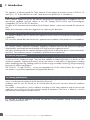 4
4
-
 5
5
-
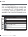 6
6
-
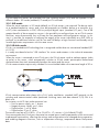 7
7
-
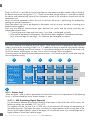 8
8
-
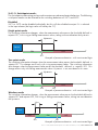 9
9
-
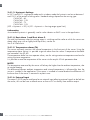 10
10
-
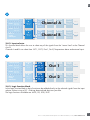 11
11
-
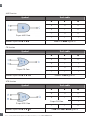 12
12
-
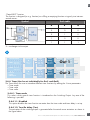 13
13
-
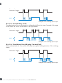 14
14
-
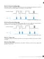 15
15
-
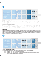 16
16
-
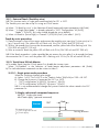 17
17
-
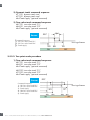 18
18
-
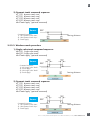 19
19
-
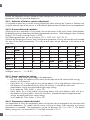 20
20
-
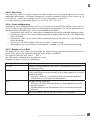 21
21
-
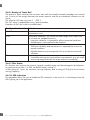 22
22
-
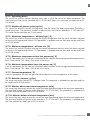 23
23
-
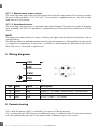 24
24
-
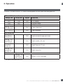 25
25
-
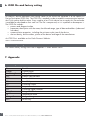 26
26
-
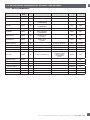 27
27
-
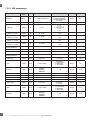 28
28
-
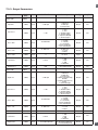 29
29
-
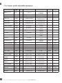 30
30
-
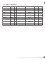 31
31
-
 32
32
-
 33
33
-
 34
34
-
 35
35
-
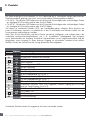 36
36
-
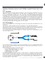 37
37
-
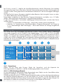 38
38
-
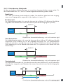 39
39
-
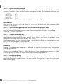 40
40
-
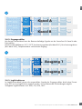 41
41
-
 42
42
-
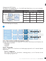 43
43
-
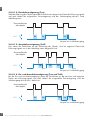 44
44
-
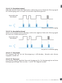 45
45
-
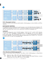 46
46
-
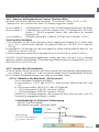 47
47
-
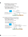 48
48
-
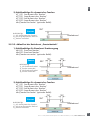 49
49
-
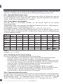 50
50
-
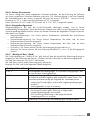 51
51
-
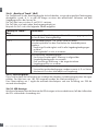 52
52
-
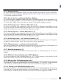 53
53
-
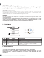 54
54
-
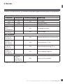 55
55
-
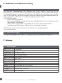 56
56
-
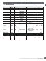 57
57
-
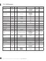 58
58
-
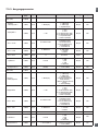 59
59
-
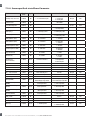 60
60
-
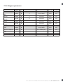 61
61
-
 62
62
-
 63
63
-
 64
64
-
 65
65
-
 66
66
-
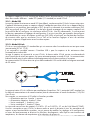 67
67
-
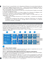 68
68
-
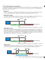 69
69
-
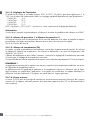 70
70
-
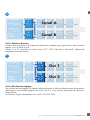 71
71
-
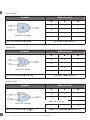 72
72
-
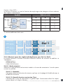 73
73
-
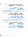 74
74
-
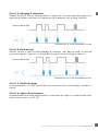 75
75
-
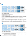 76
76
-
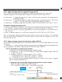 77
77
-
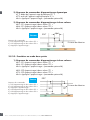 78
78
-
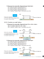 79
79
-
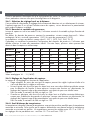 80
80
-
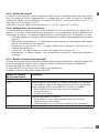 81
81
-
 82
82
-
 83
83
-
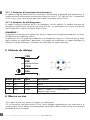 84
84
-
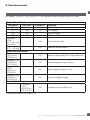 85
85
-
 86
86
-
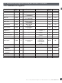 87
87
-
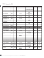 88
88
-
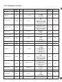 89
89
-
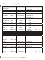 90
90
-
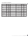 91
91
-
 92
92
-
 93
93
-
 94
94
-
 95
95
-
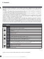 96
96
-
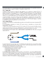 97
97
-
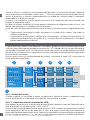 98
98
-
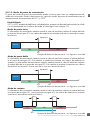 99
99
-
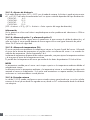 100
100
-
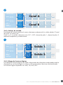 101
101
-
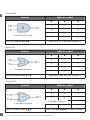 102
102
-
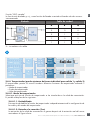 103
103
-
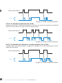 104
104
-
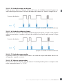 105
105
-
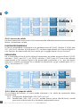 106
106
-
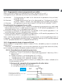 107
107
-
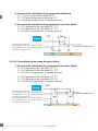 108
108
-
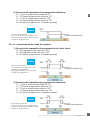 109
109
-
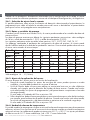 110
110
-
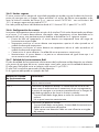 111
111
-
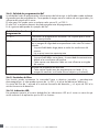 112
112
-
 113
113
-
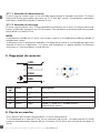 114
114
-
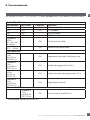 115
115
-
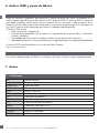 116
116
-
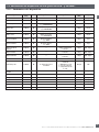 117
117
-
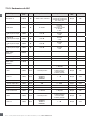 118
118
-
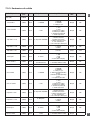 119
119
-
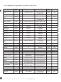 120
120
-
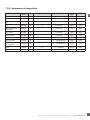 121
121
-
 122
122
-
 123
123
-
 124
124
-
 125
125
-
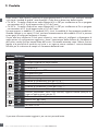 126
126
-
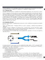 127
127
-
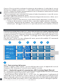 128
128
-
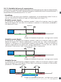 129
129
-
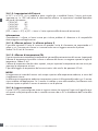 130
130
-
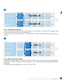 131
131
-
 132
132
-
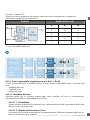 133
133
-
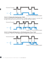 134
134
-
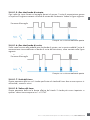 135
135
-
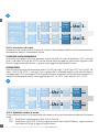 136
136
-
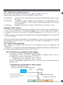 137
137
-
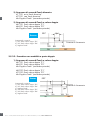 138
138
-
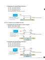 139
139
-
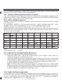 140
140
-
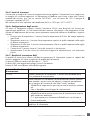 141
141
-
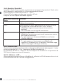 142
142
-
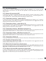 143
143
-
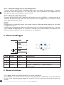 144
144
-
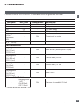 145
145
-
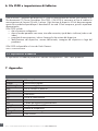 146
146
-
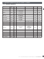 147
147
-
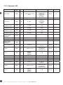 148
148
-
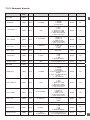 149
149
-
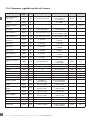 150
150
-
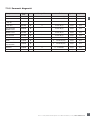 151
151
-
 152
152
-
 153
153
-
 154
154
-
 155
155
-
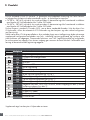 156
156
-
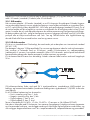 157
157
-
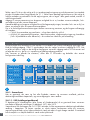 158
158
-
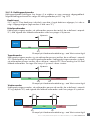 159
159
-
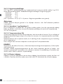 160
160
-
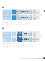 161
161
-
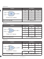 162
162
-
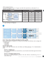 163
163
-
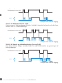 164
164
-
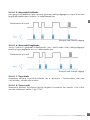 165
165
-
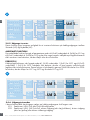 166
166
-
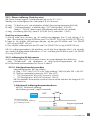 167
167
-
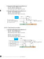 168
168
-
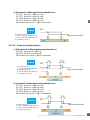 169
169
-
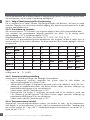 170
170
-
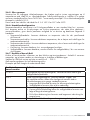 171
171
-
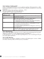 172
172
-
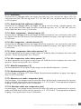 173
173
-
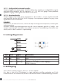 174
174
-
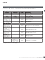 175
175
-
 176
176
-
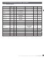 177
177
-
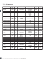 178
178
-
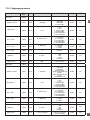 179
179
-
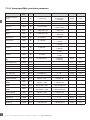 180
180
-
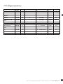 181
181
-
 182
182
-
 183
183
-
 184
184
-
 185
185
-
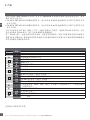 186
186
-
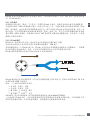 187
187
-
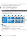 188
188
-
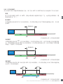 189
189
-
 190
190
-
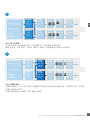 191
191
-
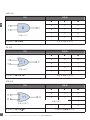 192
192
-
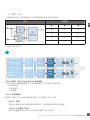 193
193
-
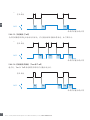 194
194
-
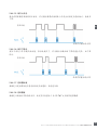 195
195
-
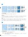 196
196
-
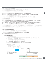 197
197
-
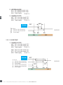 198
198
-
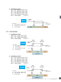 199
199
-
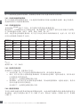 200
200
-
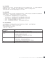 201
201
-
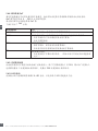 202
202
-
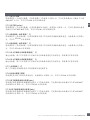 203
203
-
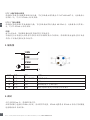 204
204
-
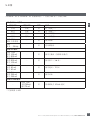 205
205
-
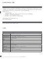 206
206
-
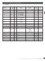 207
207
-
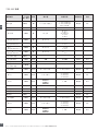 208
208
-
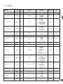 209
209
-
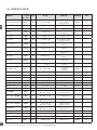 210
210
-
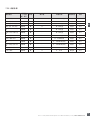 211
211
-
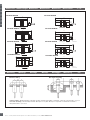 212
212
-
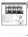 213
213
-
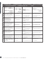 214
214
-
 215
215


CARLO GAVAZZI CA18CAN12BPM1IO El manual del propietario
- Tipo
- El manual del propietario
- Este manual también es adecuado para
en otros idiomas
Artículos relacionados
-
CARLO GAVAZZI CA18CAN12BPM1IO Manual de usuario
-
CARLO GAVAZZI CA18FAN12BPM1IO Manual de usuario
-
-
-
-
-
-
-
-
