Yamaha MA2030 El manual del propietario
- Categoría
- Equipo de música suplementario
- Tipo
- El manual del propietario
Este manual también es adecuado para

First, please carefully read the “IMPORTANT SAFETY INSTRUCTIONS” on the reverse side.
Thank you for your purchase of the Yamaha MA2030/PA2030 power amplifier. Please read through this
manual carefully before beginning use, so that you will be able to take full advantage of the device’s
various functions. After you have read the manual, keep it in a safe place.
• The illustrations as shown in this manual are for instructional purposes only.
• The company names and product names in this manual are the trademarks or registered trademarks of
their respective companies.
• In this manual, the
mark indicates content that is unique to the MA2030, and indicates
content unique to the PA2030. Contents that are common to both have no marks.
• Amplifier illustrations are mainly from the MA2030. Where necessary, illustrations of the PA2030 are also
shown.
Features
• Supports both kinds of speaker connection: high-impedance connection and low-impedance
connection.
• Equipped with digital processor (Feedback Suppressor, Ducker, Leveler).
• Optional PA2030 expansion amplifier enables connection of additional speakers.
Included items
• Power cord (2.0m)
• Euroblock plugs (3-pin, 3.50mm pitch) x 1 , x 2
• Technical Specifications (English only): includes block diagram, dimensions, and input/output
specifications.
• Owner’s Manual (this sheet)
Setup
Option 2
Speaker expansion
Option 1
Microphones
Option 3
Control Panel
(DCP1V4S)
Step 1
Speakers
Step 2
Portable audio player,
etc.
Step 2
CD players, tuners, etc.
To AC outlet
Step 3
Volume adjustment
Step 4
Front panel
Rear panel
Connecting Speakers
Step
1
Change the setting depending on the speaker connection (high- or low-impedance connection), the kind
of speakers, and the installation location of the speakers. Refer to “Connecting Speaker Cables” at the
right bottom on this page and the explanation of high-impedance connection, etc. at the following URL.
Yamaha Pro Audio site: “Better Sound for Commercial Installations”:
http://www.yamahaproaudio.com/global/en/training_support/better_sound/
Caution
• Before connecting speakers, make sure that the power of the device is turned off. If the power is on, there is a risk of
electrical shock.
• Ensure that load is not applied to the speaker cable.
• In a high-impedance installation, make sure that the sum of the power input ratings of the speakers to be connected
does not exceed 60W.
• In a low-impedance installation, make sure that the total impedance of speakers to be connected is at least 3 ohms.
■
High-impedance Connections (60W x 1 channel)
Maximum output
voltage: 100V
Maximum output
voltage: 70V
1
Set the speaker output to high-impedance by setting the [OUTPUT] switch to
[100V] or [70V] corresponding to the maximum output voltage.
2
Use speaker cables to connect the [SPEAKERS A] terminal to the positive “+”
terminals of the speakers, and the [SPEAKERS B] terminal to the negative “-”
terminals.
In case of high-impedance connection, the [SPEAKERS A] and [SPEAKERS B] terminals are
not used. Do not connect to the terminals.
Note
The speaker output is processed through a high pass filter (80Hz, 18dB/oct.).
■
Low-impedance Connections (30W x 2 channels)
[SETUP] DIP switch 1
Speaker impedance
4Ω or more
up
3Ω to 4Ω
down
1
Set the speaker output to low-impedance connection by setting the [OUTPUT] switch
to [4Ω 3Ω].
2
Set the [SETUP] DIP switch 1 to [4Ω] (up, impedance: 4Ω or more) or [3Ω] (down,
impedance: 3Ω to 4Ω) corresponding to the specications of the speakers to be
connected.
3
Connect the [SPEAKERS A] / terminals to the “+”/“-” terminals of the rst
speaker, and the [SPEAKERS B]
/ terminals to the “+”/“-” terminals of the second
speaker.
■
Configuration of Speaker Output Signal
Connecting Yamaha Speakers
[SETUP] DIP switch 4/5
Setting the [SETUP] DIP switches optimizes the
output signal to match Yamaha speakers designed
for commercial installations.
[SETUP] DIP switch 4 5
Yamaha speakers
designed for
commercial installations
Surface
mount-type
down
up
Ceiling-type
down
down
Non-Yamaha speakers
up
—
—: Setting is not required. (Either up or down can be used.)
Setting mono/stereo output
[SETUP] DIP switch 7
In a low-impedance installation, if speakers are
placed in a stereo arrangement, set to stereo
output.
[SETUP] DIP switch 7
High-impedance
connections
— Mono output
Low-impedance
connections
up
Mono output
down
Stereo output (*1)
—: Setting is not required. (Either up or down can be used.)
*1: When stereo audio is output, the left channel signal
is output from the [SPEAKERS A] terminals and the
right channel signal is output from the [SPEAKERS B]
terminals.
Connecting External Devices
Step
2
MA2030 front panel
mini-stereo
type
RCA type RCA type Euroblock
MA2030 rear panel PA2030 rear panel
Connect a BGM (background music) tuner, a CD player, a portable audio player, etc. to the stereo input jacks
of this device.
Jack position Jack name Jack type
MA2030
Front panel [ST IN 1] jack mini-stereo type (unbalanced input)
Rear panel
[ST IN 2] jack
[ST IN 3] jack
RCA type (unbalanced input)
PA2030 Rear panel [LINE IN] jack
Euroblock connector (balanced input; connect with supplied
Euroblock plugs), RCA type (unbalanced input)
Note Refer to “Attaching Euroblock Plugs” for Euroblock plug installation.
1
Make sure that this device and all devices to be connected are turned off.
2
Connect this device and any external devices with appropriate cables.
Leveler (suppressing wide playback volume variations)
[SETUP] DIP switch 6
The Leveler function automatically suppresses and corrects for large changes
in the playback volume from external devices for a more consistent sound,
such as when reproducing BGM (background music).
[SETUP] DIP switch 6
Leveler disabled
up
Leveler enabled
down
Connecting Power Cord and Turning On
Step
3
MA2030 front panel MA2030 rear panel
Power cord
AC IN connector
To AC outlet
1
Make sure power switches of this device and devices connected to this device are
turned off (in position).
2
Turn the [VOLUME] knob all the way to the left.
3
Connect the supplied power cord to the AC IN connector.
4
Insert the power cord plug into an appropriate outlet.
5
After turning on the connected devices (portable audio players, CD players, etc.), turn
on this device.
Note • Before turning on the power, please check that there are no problems with the cabling, connections, and so on.
• When turning the system off, turn off this device, and then connected devices.
Adjusting Volume
Step
4
MA2030 front panel PA2030 front panel
1
Select a stereo input by rotating the [ST SOURCE] knob.
The [ST SOURCE] indicator corresponding to the selected input signal lights.
2
Input audio signal from the external device, and conrm that sound is being output
from the speakers by gradually rotating the [VOLUME] knob to the right.
Make sure that the [VOLUME SIGNAL] indicator lights according to the sound input and that sound
comes from the speakers.
Matching the volume levels of external devices (including microphones)
When connecting two or more external devices, you can lower the volume of the louder devices (or
microphones) to match the level of the faintest device. If you are using microphones, follow the instructions in
“Option 1 Using Microphones” before executing the operation below.
1
Select the stereo input with the loudest sound by rotating the [ST SOURCE] knob.
2
Press and hold the [ST SOURCE] knob until the [ST SOURCE] indicator ashes.
3
Rotate the [ST SOURCE] knob to the left until the volume decreases to the point that
lowers as loud as that of the faintest sounding stereo input (or microphones).
As the volume becomes fainter, the flashing rate of the [ST SOURCE] indicator becomes slower.
4
Push the [ST SOURCE] knob to complete the adjustment.
The [ST SOURCE] indicator lights.
Note
Adjustable range: -18dB – 0dB
Using Microphones
Option
1
MA2030 front panel
Phone
Euroblock
XLR
MA2030 rear panel
1
Turn the [MIC IN 1] knob or the [MIC IN 2 GAIN] trimmer all the way to the left, and
connect a microphone to the [MIC IN 1] jack or the [MIC IN 2] connector.
2
Set the [VOLUME] knob to roughly a 2:00 position.
3
Loudly speak into the microphone, and turn the [MIC IN 1] knob or the [MIC IN 2 GAIN]
trimmer to the right until the output signal is not distorted.
If you input a loud voice but the output is small, raise the volume with the [VOLUME] knob.
If the sound out of the speakers is too loud, lower the volume with the [MIC IN 1] knob or the [MIC IN 2
GAIN] trimmer.
4
Make sure the input from external devices matches the volume levels of the
microphones and the external devices.
Refer to “Matching the volume levels of external devices (including microphones)” in “Step 4 Adjusting
Volume” for instructions.
Note
• To adjust the [MIC IN 2 GAIN] trimmer, use a slotted screw driver.
• Refer to “Attaching Euroblock Plugs” for installation of Euroblock plugs.
• The input signal is always processed through a high pass filter (120Hz, 12dB/oct.) to cut off low frequency signals
as well as a Feedback Suppressor to suppress howling.
Ducker (lowering the volume of the other channels automatically when a
microphone signal is input)
[SETUP] DIP switch 2/3
Jack/connector [MIC IN 1] [MIC IN 2]
Note • If both Duckers of the [MIC IN 1] jack and the [MIC
IN 2] jack are enabled, the Ducker for the [MIC IN
1] takes priority.
• Activating the Ducker lowers the output volume of
the stereo inputs by 24dB and mutes that of the
other microphone input.
[SETUP] DIP switch 2 3
Ducker disabled
up
up
Ducker enabled
down
down
Expanding Speakers
Option
2
MA2030 rear panel
RCA RCA
PA2030 rear panel
Connecting the MA2030 and PA2030 lets you increase the number of driven speakers. Connect the [LINE
OUT] jacks of MA2030 and the [LINE IN] jacks of PA2030.
Operating with Control Panel
Option
3
Connecting Yamaha Digital Control Panel DCP1V4S to MA2030 enables you to control the volume, to
switch inputs, etc. remotely.
1
ON
2 3 4
RJ-45
Rear panel
MA2030 rear panel
Ethernet straight cable
(CAT5e or more; 200m or less)
Yamaha Digital Control Panel
DCP1V4S
(maximum: one unit)
When connecting to MA2030,
set the DIP switch 4 to ON
(termination setting).
Sets the panel ID
The functions of the knob and the switches of DCP1V4S can be configured with DIP switches at the back
of DCP1V4S.
Panel
ID
DIP switch
1 2 3 4
Knob Switch 1 Switch 2 Switch 3 Switch 4
Volume: Adjusts the volume output
to the [SPEAKERS] terminals and
the [LINE OUT] jacks.
Stereo 1/2/3: Switches to stereo
input 1/2/3.
Mic. 1/2: Turns on/off microphone
input 1/2. When a microphone
is on, the switch indicator of the
control panel lights and the stereo
input is muted.
• If the panel ID is set to 3, the
stereo input is not muted even
though the microphone is on.
• If the panel ID is set to 7, the
microphone stays on while
holding the switch.
: A chime sounds when the
microphone is turned on/off
—: Does not work. (No function is
assigned.)
0
Volume
— — — —
1
Stereo 1 Stereo 2 Stereo 3 —
2
Mic. 1 Mic. 2
Mic. 1 Mic. 2
3
Mic. 1 Mic. 2
Mic. 1 Mic. 2
4
Mic. 1
— Mic. 1 —
5
Mic. 2
— Mic. 2 —
6
Mic. 1 Mic. 2 — —
7
Mic. 1 Mic. 2 — —
Note Refer to “DCP1V4S Owner’s Manual” for DCP1V4S installation.
Connecting Speaker Cables
The [SPEAKERS] output connectors on the rear panel are barrier strip type connectors. The connections
are described below for two methods: using a spade lug and using a bare conductor.
Caution
Ensure that load is not applied to the speaker cable.
Note Connect the cables so that the amplifier’s “+” and “-” symbols match those of the speaker. If they are reversed,
the phase will be reversed and the sound will not be output correctly.
When using a spade lug
Loosen the screw, insert the spade lug all the
way from below, and tighten the screw.
≤5.8mm
(≤0.23")
≥3.2mm
(≥ 0.13")
When using a bare conductor
Loosen the screw, wrap the conductor wire around
the barrier strip terminal, and tighten the screw. Be
sure that the bare wire does not touch the chassis.
* Actual size
15mm
*
(0.6")
Speaker cable
Wire
should not
touch the
chassis.
Attaching Euroblock Plugs
1 2 3 4
Loosen
Tighten
Slotted
screwdriver
Approx. 5 mm
(approx. 0.2")
Terminal
screw
Euroblock plug
Note • You must use the supplied Euroblock plugs. If the plugs have been lost, please contact your Yamaha dealer.
• To prepare the cable for attachment to a Euroblock connector, strip the wire as shown in the illustration using
stranded wire to make connections. With a Euroblock connection, stranded wires may be prone to breakage
because of metal fatigue due to the weight of the cable or due to vibration. When rack mounting your device,
use a lacing bar when possible to bundle and fasten the cables.
• Do not tin (solder) the exposed end.
1
Loosen terminal screws.
2
Insert cables.
3
Securely tighten terminal screws.
4
Insert the Euroblock plug into the [MIC IN 2] terminal of MA2030 or the [LINE IN]
terminal of PA2030.
Panel Lock
Changes by several knobs can be locked, so that the settings of the device are not affected by accidental
touch or unauthorized operation. The [ST SOURCE], [SOURCE EQ BASS] and [SOURCE EQ TREBLE]
knobs can be locked.
1
Adjust the [ST SOURCE], [SOURCE EQ BASS] and [SOURCE EQ TREBLE] knobs
to the desired fixed settings.
2
Turn off the power.
3
Set DIP switch 8 to the downward position.
4
Turn the power back on again.
Note To unlock, turn off the power, set DIP switch 8 to the upward position, and turn on the power.
ZJ24810
EN
POWER AMPLIFIER
Owner’s Manual

Troubleshooting
Symptom Cause Solution
The power does not
turn on.
The power cord is disconnected. Connect the power cord.
The protection function of the device has been
activated.
Turn off the power switch and make sure the
connection is secure. Wait several minutes, and then
turn on the power again.
No sound is heard. The sound is lowered too much with the
[VOLUME] knob.
Turn the [VOLUME] knob to the right.
No audio signal is being input. Make sure that this device is properly connected to
external devices.
Make sure that the external device outputs audio
signal.
The input is not selected. Turn the [ST SOURCE] to select input jacks connected
to an external device.
The connected microphone is a condenser type. Use a dynamic type microphone or supply phantom
power to the condenser microphone.
The sound distorts. The input level from microphones or external
devices is too high.
Turn the [MIC IN 1] knob/the [MIC IN 2 GAIN] trimmer
to the left to lower the volume of the microphones.
Lower the input volume from the external devices.
The EQ level is too high. Turn the [SOURCE EQ BASS]/[SOURCE EQ TREBLE]
knob to the left to lower the EQ.
The setting does not
change even when
turning a knob.
The panel is locked. When the panel is locked,
even when turning the [ST SOURCE] knob,
[SOURCE EQ BASS] knob or [SOURCE EQ
TREBLE] knob, the setting of the device does
not change.
Set DIP switch 8 to the upward position and turn on
the power again.
The sound is small. The device is set to low-impedance connection;
however, speakers with high-impedance input
have been connected.
Match the impedance settings of this device and the
connected speakers.
The sound drops
out and the power
indicator flashes
three times.
The device is set to high-impedance connection;
however, speakers with low-impedance input
have been connected or too many speakers are
connected.
Match the impedance setting and the input rating
setting of this device and the speakers.
When the device is set to low-impedance
connection, the total impedance of the
connected speakers is less than the impedance
setting of this device.
Match the impedance settings of this device and the
speakers.
The speaker cable is shorted. Inspect the connection of the speaker cables.
The power indicator
continues flashing.
The internal temperature of the device is
extremely high.
Turn off the power, leave the device at a well-ventilated
place, and turn on the device several minutes later.
• Refer also to the Yamaha Pro Audio website that provides a FAQ (a list of frequently asked questions, with answers).
http://www.yamahaproaudio.com/
• If taking the above steps does not solve the problem, contact your Yamaha dealer for repair.
Specifications (MA2030/PA2030)
Output Power
(20 msec burst, THD+N=1%)
3Ω/4Ω 30 W x 2 ch
70 V/100 V 60 W x 1 ch
Amplier Type (Output circuitry) Class D
THD+N
Stereo in à Speaker out,
1 kHz, 15 W, 3Ω/4Ω
≤
0.1%
Stereo in à Speaker out,
1 kHz, 30 W, 70 V/100 V
≤
0.2%
Frequency Response
Line in à Line out,
20 Hz–20 kHz (MA2030 only)
0 dB, -2.5 dB, +1.0 dB
Line in à Speaker out,
50 Hz–20 kHz, 1 W, 3Ω/4Ω
0 dB, -3.0 dB, +1.0 dB
Line in à Speaker out,
90 Hz–20 kHz, 1 W, 70 V/100 V
0 dB, -3.0 dB, +1.0 dB
Crosstalk
(MA2030 only)
Stereo in to other Stereo in
≤
-70 dB
AC Power Requirement
100 V/120 V/230 V-240 V,
50 Hz/60 Hz
Power Consumption
(3Ω, AC 100 V)
1/8 max. power,
pink noise at all channel,
30 W
Idle 25 W
Operating Temperature 0°C–+40°C
Storage Temperature -20°C–+60°C
Dimensions (W x H x D, including knob)
215 x 54 x 288 mm
(8.5 x 2.1 x 11.4 inch)
Net Weight
1.8 kg
(4.0 lbs)
Optional Accessories
Rack-mount Accessory RKH1
Digital Control Panel DCP1V4S
* The contents of this manual apply to the latest specifications as of the printing date. Since Yamaha makes continuous
improvements to the product, this manual may not apply to the specifications of your particular product. To obtain the
latest manual, access the Yamaha website then download the manual file. Since specifications, equipment or separately
sold accessories may not be the same in every locale, please check with your Yamaha dealer.
European Models
Inrush Current based on EN 55103-1:2009
3.0A (on initial switch-on)
2.0A (after a supply interruption of 5s)
Conforms to Environments: E1, E2, E3 and E4
Rear panel
7 8 9 0 A B C D
7 9 0 E8
MA2030
PA2030
7
AC IN connector
Connect the supplied power cord.
Caution
• When connecting the power cord, connect the power cord to the connector and then plug it into an appropriate AC power
outlet.
• Before connecting or disconnecting the power cord, make sure that the power to the device is turned off.
8
[SPEAKERS] output terminals
Barrier strip type speaker output connectors. Refer to “Connecting Speaker Cables” for the installation instructions.
9
[OUTPUT] switch
Sets the output type of amplifier: high-impedance connection ([100V], [70V]) or low-impedance connection ([4Ω
3Ω]). The setting change will be reflected after turning on again.
Front panel
MA2030 (PA2030 has only
4
and
6
)
1 2 3 4 5 6
1
[MIC IN 1] jack
Combo input jack that accepts both phone-type and XLR-type. Connect dynamic microphones mainly. Input signal
is always processed through high pass filter (120Hz, 12dB/oct.) to cut off low frequency signal and Feedback
Suppressor to suppress howling.
[MIC IN 1 SIGNAL] indicator
Lights when signal is input to the [MIC IN 1] jack.
[MIC IN 1] knob
Adjusts the volume of the microphone connected to the [MIC IN 1] jack. Turning to the right increases the volume.
2
[ST IN 1] jack
Input jack of mini-stereo type (unbalanced input).
Connect a stereo audio source such as portable audio players.
3
[ST SOURCE] indicator 1/2/3
Selecting input signal from the [ST IN 1] jack lights indicator 1, the [ST IN 2] jacks lights indicator 2, and the [ST IN 3]
jacks lights indicator 3.
[ST SOURCE] knob
Rotating this switches among the stereo input signals.
Pressing and holding this lets you adjust the volume balance of stereo inputs.
Refer to “Matching the volume levels of external devices” (Step 4).
4
[VOLUME SIGNAL] indicator
Lights when signal output to speakers exceeds a
certain level.
[VOLUME LIMIT] indicator
Lights if signal output to the speakers exceeds
the limit value, causing the limiter to activate, or if
the internal temperature of the device increases
abnormally. If the limiter activates, turn the
[VOLUME] knob to the left so the indicator light goes out. If the device internal temperature increases, leave the device
without turning on the power until the internal temperature goes down.
[VOLUME] knob
Adjusts the volume output to the speakers. Turning to the right increases the volume. Turning all the way to the left mutes
the sound.
5
[SOURCE EQ BASS] knob
Adjust the volume of the low frequency (around 125Hz) stereo signal from -10dB to +10dB. At the center position, the sound
is flat; turning to the left lowers the low frequency signal and turning to the right increases the low frequency signal. Turning to
the right 90 degrees or more from the center activates the Enhancer to further emphasize the low frequency signal.
[SOURCE EQ TREBLE] knob
Adjust the volume of the high frequency (6 kHz or more) stereo signal from -10dB to +10dB. At the center position, the sound
is flat; turning to the left lowers the high frequency signal and turning to the right increases the high frequency signal. Turning
to the right 90 degrees or more from the center activates the Enhancer to further emphasize the high frequency signal.
Note If the sound distorts when using EQ, turn the knob to the left until the sound is not distorted or lower the volume of the
stereo source.
6
Power indicator
Turns on when the power is on.
If flashing continues for 10 seconds or more, the internal temperature of the device is extremely high. Turn off the power
once, and turn on again several minutes later.
Power switch
Turn on/off the power.
Caution
• To ensure that high-volume noise is not output from the speakers, power on the connected device first and then turn on this
device. When turning the system off, turn off this device, and then the connected devices.
• After turning the power switch off, wait for about five seconds before turning it on again. Rapidly turning the power switch on
and off in succession can cause the unit to malfunction.
• Even when the switch is in the off position, a small amount of electricity is still flowing to the unit. If it will not be used for an
extended period of time, therefore, be sure to unplug the power cord from the wall AC outlet.
Note Do not turn off the power switch three seconds or less after executing an operation. If you do, some setting information may
not be saved.
0
[SETUP] DIP switches
Set the following functions of the device. The setting change will be reflected after turning on again.
number setting function
up
down
1 OUTPUT
Sets the speaker impedance if the [OUTPUT] switch is
set to [4Ω 3Ω] (low-impedance connection).
4Ω 3Ω
2 MIC 1 DUCKER
Turns on/off the Ducker of the [MIC in 1] jack. OFF ON
3 MIC 2 DUCKER
Turns on/off the Ducker of the [MIC in 2] jack. OFF ON
4
SP EQ
Sets the speaker output to appropriate frequency
characteristics for Yamaha speakers designed for
commercial installations.
OFF ON
5
If DIP switch 4 is set to on, this optimizes for the type of
Yamaha speakers designed for commercial installations
SURFACE CEILING
6 LEVELER
Turn on/off the Leveler. OFF ON
7 MIXER
In low-impedance installation of speakers, this sets the
speaker output to stereo or mono.
MONO STEREO
8 PANEL LOCK
Several knobs on the front panel are locked. Refer to
“Panel Lock” for details.
UNLOCK LOCK
Note • When the device is shipped from the factory, the DIP switches are all in the up position.
• If DIP switches 2 and 3 (MIC 1 DUCKER and MIC 2 DUCKER) are set to on, when both microphones are used
simultaneously, the [MIC IN 1] jack is prioritized and the microphone input that connected to the [MIC IN 2] connector is
muted.
• The output of the [LINE OUT] jacks does not reflect the stereo/mono setting in [SETUP] DIP switch 7 (MIXER).
A
[DCP] connector
Connect one Yamaha Digital Control Panel DCP1V4S. Refer to “Option 3 Operating with Control Panel” for connection
method.
B
[LINE OUT] jacks
RCA type stereo output jack (unbalanced output). Outputs to the [LINE IN] jacks of PA2030 and line input jacks of other
external devices. Outputs a mixed signal of the selected stereo input, the [MIC IN 1] jack input and the [MIC IN 2] jack input.
C
[ST IN 2] jacks/[ST IN 3] jacks
RCA type stereo input jack (unbalanced output). Connect external devices such as CD player, etc. Select input jacks with
the [ST SOURCE] knob on the front panel.
D
[MIC IN 2] connector
Euroblock 3-pin connector for microphone audio input (balanced). Refer to “Attaching Euroblock Plugs” for Euroblock
plug installation. The input signal is always processed through a high pass filter (120Hz, 12dB/oct.) to cut off low
frequency signals as well as a Feedback Suppressor to suppress howling.
[MIC IN 2 GAIN] trimmer
Adjust the volume of microphone that is connected to the [MIC IN 2] connector. Adjust with a slotted driver of the correct size.
E
[LINE IN] jacks/connectors
RCA type and Euroblock 3-pin stereo input jacks/connectors (RCA: unbalanced; Euroblock 3-pin: balanced). Connect to
the [LINE OUT] jacks of the MA2030 or output jacks of other external devices. The signals input from the RCA type jacks
and Euroblock connector will be mixed to the output.
Controls and Connectors
Setting
Signal level for which each indicator turns on
[VOLUME SIGNAL]
Low-impedance
connections
[3Ω] -18.2 dBu or more
[4Ω] -17.0 dBu or more
High-impedance
connections
[70V] -0.8 dBu or more
[100V] 2.3 dBu or more
PLEASE READ CAREFULLY BEFORE
PROCEEDING
Please keep this manual in a safe place for future reference.
WARNING
Always follow the basic precautions listed below to avoid
the possibility of serious injury or even death from electrical
shock, short-circuiting, damages, re or other hazards. These
precautions include, but are not limited to, the following:
Power supply/power cord
• Do not place the power cord near heat sources such as heaters
or radiators, and do not excessively bend or otherwise damage
the cord, place heavy objects on it, or place it in a position
where anyone could walk on, trip over, or roll anything over it.
• Only use the voltage specified as correct for the device. The
required voltage is printed on the name plate of the device.
• Use only the supplied power cord. If you intend to use the
device in an area other than in the one you purchased, the
included power cord may not be compatible. Please check
with your Yamaha dealer.
• Check the electric plug periodically and remove any dirt or
dust which may have accumulated on it.
• Be sure to connect to an appropriate outlet with a protective
grounding connection. Improper grounding can result in
electrical shock, damage to the device(s), or even fire.
Do not open
• This device contains no user-serviceable parts. Do not
open the device or attempt to disassemble the internal
parts or modify them in any way. If it should appear to be
malfunctioning, discontinue use immediately and have it
inspected by qualified Yamaha service personnel.
Water warning
• Do not expose the device to rain, use it near water or in damp
or wet conditions, or place on it any containers (such as vases,
bottles or glasses) containing liquids which might spill into any
openings. If any liquid such as water seeps into the device,
turn off the power immediately and unplug the power cord from
the AC outlet. Then have the device inspected by qualified
Yamaha service personnel.
• Never insert or remove an electric plug with wet hands.
Fire warning
• Do not put burning items, such as candles, on the unit. A
burning item may fall over and cause a fire.
If you notice any abnormality
• When one of the following problems occur, immediately turn off
the power switch and disconnect the electric plug from the outlet.
Then have the device inspected by Yamaha service personnel.
– The power cord or plug becomes frayed or damaged.
– It emits unusual smells or smoke.
– Some object has been dropped into the instrument.
– There is a sudden loss of sound during use of the device.
• If this device should be dropped or damaged, immediately turn off
the power switch, disconnect the electric plug from the outlet, and
have the device inspected by qualified Yamaha service personnel.
CAUTION
Always follow the basic precautions listed below to avoid the
possibility of physical injury to you or others, or damage to
the device or other property. These precautions include, but
are not limited to, the following:
Power supply/power cord
• When removing the electric plug from the device or an outlet,
always hold the plug itself and not the cord. Pulling by the cord
can damage it.
• Remove the electric plug from the outlet when the device is not to
be used for extended periods of time, or during electrical storms.
Location
• Do not place the device in an unstable position where it might
accidentally fall over.
• Do not block the vents. This device has ventilation holes at the top/
bottom/sides to prevent the internal temperature from becoming
too high. In particular, do not place the device on its side or
upside down. Inadequate ventilation can result in overheating,
possibly causing damage to the device(s), or even fire.
• When attempting to dissipate heat on the device, when
installing it:
– Do not cover it with any cloth.
– Do not install it on a carpet or rug.
– Make sure the top surface faces up; do not install on its
sides or upside down.
– Do not use the device in a confined, poorly-ventilated
location.
Inadequate ventilation can result in overheating, possibly
causing damage to the device(s), or even fire.
Make sure that there is adequate space around the device: at
least 10 cm above, 1 cm below the bottom surface, 10 cm at
the sides and 10 cm behind.
• Do not place the device in a location where it may come into
contact with corrosive gases or salt air. Doing so may result in
malfunction.
• Before moving the device, remove all connected cables.
• When setting up the device, make sure that the AC outlet you
are using is easily accessible. If some trouble or malfunction
occurs, immediately turn off the power switch and disconnect
the plug from the outlet. Even when the power switch is turned
off, electricity is still flowing to the product at the minimum
level. When you are not using the product for a long time,
make sure to unplug the power cord from the wall AC outlet.
• If the device is mounted in an EIA standard rack, carefully
read the section “Precautions for rack mounting”. Inadequate
ventilation can result in overheating, possibly causing damage
to the device(s), malfunction, or even fire.
Connections
• Before connecting the device to other devices, turn off the
power for all devices. Before turning the power on or off for all
devices, set all volume levels to minimum.
• Use only speaker cables for connecting speakers to the
speaker jacks. Use of other types of cables may result in fire.
Maintenance
• Remove the power plug from the AC outlet when cleaning the
device.
Handling caution
• When the surface of the device heats up, do not touch it until
the panel temperature goes down. Touching the surface with
its high temperature may cause burns.
• Avoid inserting or dropping foreign objects (paper, plastic,
metal, etc.) into any gaps or openings on the device (vents,
etc.) If this happens, turn off the power immediately and
unplug the power cord from the AC outlet. Then have the
device inspected by qualified Yamaha service personnel.
• Do not rest your weight on the device or place heavy objects
on it, and avoid use excessive force on the buttons, switches
or connectors.
• Do not use the device for a long period of time at a high or
uncomfortable volume level, since this can cause permanent
hearing loss. If you experience any hearing loss or ringing in
the ears, consult a physician.
• Do not operate the device if the sound is distorting. Prolonged
use in this condition could cause overheating and result in fire.
Yamaha cannot be held responsible for damage caused by
improper use or modifications to the device, or data that is lost
or destroyed.
NOTICE
To avoid the possibility of malfunction/ damage to the product, or
damage to other property, follow the notices below.
Handling and maintenance
• Do not use the device in the vicinity of a TV, radio, stereo
equipment, mobile phone, or other electric devices. Otherwise,
the device, TV, or radio may generate noise.
• Do not expose the device to excessive dust or vibration, or
extreme cold or heat (such as in direct sunlight, near a heater,
or in a car during the day), in order to prevent the possibility
of panel disfiguration, unstable operation, or damage to the
internal components.
• Do not place vinyl, plastic or rubber objects on/under the
device, since this might discolor the panel of the device or the
objects placed on/under the device.
• Keep input cables of microphone, etc., devices that contain
sensitive circuits, and the power cord at a distance from
speaker cables and fasten the speaker cables in place.
Since a large amount of current can flow in a speaker cable,
a magnetic field will be generated and may produce radio
interference and acoustic noise.
• When cleaning the device, use a dry and soft cloth. Do not
use paint thinners, solvents, cleaning fluids, or chemical-
impregnated wiping cloths.
• Condensation can occur in the device due to rapid, drastic
changes in ambient temperature–when the device is moved
from one location to another, or air conditioning is turned
on or off, for example. Using the device while condensation
is present can cause damage. If there is reason to believe
that condensation might have occurred, leave the device
for several hours without turning on the power until the
condensation has completely dried out.
• Avoid setting all equalizer controls and faders to their
maximum. Depending on the condition of the connected
devices, doing so may cause feedback and may damage the
speakers.
• Do not use this device for any purpose other than driving
loudspeakers.
• When turning on the AC power in your audio system, always
turn on the device LAST, to avoid speaker damage. When
turning the power off, the device should be turned off FIRST for
the same reason.
• If you put the device on a table or a rack, do not remove the
rubber feet from the device.
• Always turn the power off when the device is not in use.
Connectors
XLR-type connectors are wired as follows (IEC60268 standard):
pin 1: ground, pin 2: hot (+), and pin 3: cold (-).
Precautions for rack mounting
This unit is rated for operation at ambient temperatures ranging
from 0 to 40 degrees Celsius. If the device is mounted with
other devices in an EIA standard equipment rack, internal
temperatures can exceed the specified upper limit, resulting in
impaired performance or failure. If the device is mounted in a
rack, always observe the following requirements to avoid heat
buildup:
• If the device is mounted in a rack with other devices that
generate a significant amount of heat, such as a power
amplifier, leave more than 1U of space between the device
and other devices (both above and below). Also, make sure to
either leave any open spaces uncovered or install appropriate
ventilating panels to minimize the possibility of heat buildup.
• To ensure sufficient airflow, leave the rear of the rack open and
position it at least 10 centimeters from walls or other surfaces.
If you’ve installed a fan kit, there may be cases in which
closing the rear of the rack will produce a greater cooling
effect. Refer to the rack and fan unit manual for details.
PRECAUTIONS
For details of products, please contact your nearest Yamaha representative or the authorized distributor listed below.
Yamaha Pro Audio global web site:
http://www.yamahaproaudio.com/
Yamaha Manual Library
http://www.yamaha.co.jp/manual/
C.S.G., PA Development Division
© 2014 Yamaha Corporation
Published 08/2014 KSHD-B0
Printed in China
FCC INFORMATION (U.S.A.)
1. IMPORTANT NOTICE: DO NOT MODIFY THIS UNIT!
This product, when installed as indicated in the instructions
contained in this manual, meets FCC requirements.
Modifications not expressly approved by Yamaha may void
your authority, granted by the FCC, to use the product.
2. IMPORTANT:
When connecting this product to accessories and/or
another product use only high quality shielded cables.
Cable/s supplied with this product MUST be used. Follow all
installation instructions. Failure to follow instructions could
void your FCC authorization to use this product in the USA.
3. NOTE:
This product has been tested and found to comply with the
requirements listed in FCC Regulations, Part 15 for Class
“B” digital devices. Compliance with these requirements
provides a reasonable level of assurance that your use
of this product in a residential environment will not result
in harmful interference with other electronic devices. This
equipment generates/uses radio frequencies and, if not
installed and used according to the instructions found in
the users manual, may cause interference harmful to the
operation of other electronic devices. Compliance with FCC
regulations does not guarantee that interference will not occur
in all installations. If this product is found to be the source of
interference, which can be determined by turning the unit
“OFF” and “ON”, please try to eliminate the problem by using
one of the following measures:
Relocate either this product or the device that is being
affected by the interference.
Utilize power outlets that are on different branch (circuit
breaker or fuse) circuits or install AC line filter/s.
In the case of radio or TV interference, relocate/reorient
the antenna. If the antenna lead-in is 300 ohm ribbon lead,
change the lead-in to co-axial type cable.
If these corrective measures do not produce satisfactory
results, please contact the local retailer authorized to
distribute this type of product. If you can not locate the
appropriate retailer, please contact Yamaha Corporation of
America, Electronic Service Division, 6600 Orangethorpe
Ave, Buena Park, CA90620
The above statements apply ONLY to those products
distributed by Yamaha Corporation of America or its
subsidiaries.
(class B)
The model number, serial number, power requirements, etc.,
may be found on or near the name plate, which is at the
bottom of the unit.
You should note this serial number in the space provided
below and retain this manual as a permanent record of your
purchase to aid identification in the event of theft.
Model No.
Serial No.
(bottom_en_01)
IMPORTANT NOTICE FOR THE UNITED KINGDOM
Connecting the Plug and Cord
WARNING: THIS APPARATUS MUST BE EARTHED
IMPORTANT. The wires in this mains lead are coloured in
accordance with the following code:
GREEN-AND-YELLOW : EARTH
BLUE : NEUTRAL
BROWN : LIVE
As the colours of the wires in the mains lead of this apparatus
may not correspond with the coloured markings identifying
the terminals in your plug proceed as follows:
The wire which is coloured GREEN-and-YELLOW must be
connected to the terminal in the plug which is marked by the
letter E or by the safety earth symbol
or colored GREEN or
GREEN-and-YELLOW.
The wire which is coloured BLUE must be connected to the
terminal which is marked with the letter N or coloured BLACK.
The wire which is coloured BROWN must be connected to the
terminal which is marked with the letter L or coloured RED.
(3 wires)
In Finland: Laite on liitettävä suojamaadoituskoskettimilla
varustettuun pistorasiaan.
In Norway: Apparatet må tilkoples jordet stikkontakt.
In Sweden: Apparaten skall anslutas till jordat uttag.
(class I hokuo)
CAN ICES-3 (B)/NMB-3(B)
This applies only to products distributed by Yamaha Canada
Music Ltd.
(can_b_01)
This device complies with Part 15 of the FCC Rules.
Operation is subject to the following two conditions:
(1) this device may not cause harmful interference, and
(2) this device must accept any interference received,
including interference that may cause undesired operation.
(fcc_sengen-C)
이 기기는 가정용(B급) 전자파적합기기로서 주로
가정에서 사용하는 것을 목적으로 하며, 모든
지역에서 사용할 수 있습니다.
(class b korea)
CAUTION: TO REDUCE THE RISK OF
ELECTRIC SHOCK, DO NOT REMOVE
COVER (OR BACK). NO USER-SERVICEABLE
PARTS INSIDE. REFER SERVICING TO
QUALIFIED SERVICE PERSONNEL.
CAUT ION
RISK OF ELECTRIC SHOCK
DO NOT OPEN
The above warning is located on the top of the unit.
Explanation of Graphical Symbols
The lightning flash with arrowhead symbol
within an equilateral triangle is intended to
alert the user to the presence of uninsulated
“dangerous voltage” within the product’s
enclosure that may be of sufficient magnitude
to constitute a risk of electric shock to persons.
The exclamation point within an equilateral
triangle is intended to alert the user to
the presence of important operating and
maintenance (servicing) instructions in the
literature accompanying the product.
IMPORTANT SAFETY INSTRUCTIONS
1 Read these instructions.
2 Keep these instructions.
3 Heed all warnings.
4 Follow all instructions.
5 Do not use this apparatus near water.
6 Clean only with dry cloth.
7 Do not block any ventilation openings. Install in
accordance with the manufacturer’s instructions.
8 Do not install near any heat sources such as radiators,
heat registers, stoves, or other apparatus (including
ampliers) that produce heat.
9 Do not defeat the safety purpose of the polarized or
grounding-type plug. A polarized plug has two blades
with one wider than the other. A grounding type plug
has two blades and a third grounding prong. The wide
blade or the third prong are provided for your safety. If
the provided plug does not t into your outlet, consult
an electrician for replacement of the obsolete outlet.
10 Protect the power cord from being walked on or
pinched particularly at plugs, convenience receptacles,
and the point where they exit from the apparatus.
11 Only use attachments/accessories specied by the
manufacturer.
12 Use only with the cart, stand, tripod,
bracket, or table specied by the
manufacturer, or sold with the
apparatus. When a cart is used, use
caution when moving the cart/
apparatus combination to avoid injury
from tip-over.
13 Unplug this apparatus during lightning
storms or when unused for long periods of time.
14 Refer all servicing to qualied service personnel.
Servicing is required when the apparatus has been
damaged in any way, such as power-supply cord or
plug is damaged, liquid has been spilled or objects
have fallen into the apparatus, the apparatus has been
exposed to rain or moisture, does not operate normally,
or has been dropped.
WARNING
TO REDUCE THE RISK OF FIRE OR ELECTRIC SHOCK, DO NOT EXPOSE THIS APPARATUS TO RAIN OR MOISTURE.
(UL60065_03)
Information for Users on Collection and Disposal of Old Equipment
This symbol on the products, packaging, and/or accompanying documents means that used electrical and
electronic products should not be mixed with general household waste.
For proper treatment, recovery and recycling of old products, please take them to applicable collection
points, in accordance with your national legislation and the Directives 2002/96/EC.
By disposing of these products correctly, you will help to save valuable resources and prevent any potential
negative effects on human health and the environment which could otherwise arise from inappropriate waste
handling.
For more information about collection and recycling of old products, please contact your local municipality,
your waste disposal service or the point of sale where you purchased the items.
[For business users in the European Union]
If you wish to discard electrical and electronic equipment, please contact your dealer or supplier for further
information.
[Information on Disposal in other Countries outside the European Union]
This symbol is only valid in the European Union. If you wish to discard these items, please contact your local
authorities or dealer and ask for the correct method of disposal.
(weee_eu_en_01)
Transcripción de documentos
ZJ24810 EN ■■ Low-impedance Connections (30W x 2 channels) Step 4 Adjusting Volume Option 3 Operating with Control Panel Connecting Yamaha Digital Control Panel DCP1V4S to MA2030 enables you to control the volume, to switch inputs, etc. remotely. POWER AMPLIFIER RJ-45 [SETUP] DIP switch Speaker impedance Owner’s Manual First, please carefully read the “IMPORTANT SAFETY INSTRUCTIONS” on the reverse side. Thank you for your purchase of the Yamaha MA2030/PA2030 power amplifier. Please read through this manual carefully before beginning use, so that you will be able to take full advantage of the device’s various functions. After you have read the manual, keep it in a safe place. • The illustrations as shown in this manual are for instructional purposes only. • The company names and product names in this manual are the trademarks or registered trademarks of their respective companies. mark indicates content that is unique to the MA2030, and indicates • In this manual, the content unique to the PA2030. Contents that are common to both have no marks. • Amplifier illustrations are mainly from the MA2030. Where necessary, illustrations of the PA2030 are also shown. Features • Supports both kinds of speaker connection: high-impedance connection and low-impedance connection. • Equipped with digital processor (Feedback Suppressor, Ducker, Leveler). • Optional PA2030 expansion amplifier enables connection of additional speakers. Included items • Power cord (2.0m) • Euroblock plugs (3-pin, 3.50mm pitch) x 1 ,x2 • Technical Specifications (English only): includes block diagram, dimensions, and input/output specifications. • Owner’s Manual (this sheet) 1 2 3 up 3Ω to 4Ω down Rear panel MA2030 front panel 1 ■■ Configuration of Speaker Output Signal Setting the [SETUP] DIP switches optimizes the output signal to match Yamaha speakers designed for commercial installations. [SETUP] DIP switch Surface Yamaha speakers mount-type designed for 4 down commercial installations Ceiling-type down Non-Yamaha speakers up 5 up down — —: Setting is not required. (Either up or down can be used.) Setting mono/stereo output [SETUP] DIP switch 7 In a low-impedance installation, if speakers are placed in a stereo arrangement, set to stereo output. [SETUP] DIP switch High-impedance connections 4 7 — Low-impedance connections Select a stereo input by rotating the [ST SOURCE] knob. Input audio signal from the external device, and confirm that sound is being output from the speakers by gradually rotating the [VOLUME] knob to the right. up Mono output down Stereo output (*1) Option Microphones Portable audio player, etc. Option 2 Step 2 3 Option RCA type mini-stereo type — — — — 1 Stereo 1 Stereo 2 Stereo 3 — Select the stereo input with the loudest sound by rotating the [ST SOURCE] knob. 2 Mic. 1 Mic. 2 Mic. 1 Mic. 2 Press and hold the [ST SOURCE] knob until the [ST SOURCE] indicator flashes. 3 Mic. 1 Mic. 2 Mic. 1 Mic. 2 Rotate the [ST SOURCE] knob to the left until the volume decreases to the point that lowers as loud as that of the faintest sounding stereo input (or microphones). As the volume becomes fainter, the flashing rate of the [ST SOURCE] indicator becomes slower. MA2030 front panel Jack position Front panel 3 Control Panel (DCP1V4S) Volume adjustment PA2030 1 2 Connecting Speakers Change the setting depending on the speaker connection (high- or low-impedance connection), the kind of speakers, and the installation location of the speakers. Refer to “Connecting Speaker Cables” at the right bottom on this page and the explanation of high-impedance connection, etc. at the following URL. Yamaha Pro Audio site: “Better Sound for Commercial Installations”: http://www.yamahaproaudio.com/global/en/training_support/better_sound/ Rear panel Rear panel RCA type Euroblock The [ST SOURCE] indicator lights. • Before connecting speakers, make sure that the power of the device is turned off. If the power is on, there is a risk of electrical shock. • Ensure that load is not applied to the speaker cable. • In a high-impedance installation, make sure that the sum of the power input ratings of the speakers to be connected does not exceed 60W. • In a low-impedance installation, make sure that the total impedance of speakers to be connected is at least 3 ohms. 1 Mic. 1 — Mic. 1 — 5 Mic. 2 — Mic. 2 — 6 Mic. 1 Mic. 2 — — 7 Mic. 1 Mic. 2 — — Using Microphones Connecting Speaker Cables Euroblock XLR The [SPEAKERS] output connectors on the rear panel are barrier strip type connectors. The connections are described below for two methods: using a spade lug and using a bare conductor. MA2030 rear panel PA2030 rear panel Jack name [ST IN 1] jack [ST IN 2] jack [ST IN 3] jack [LINE IN] jack 3 Ducker (lowering the volume of the other channels automatically when a microphone signal is input) [SETUP] DIP switch 2/3 Jack/connector [SETUP] DIP switch [MIC IN 1] 2 [MIC IN 2] 3 6 Ducker disabled up up Leveler disabled up Ducker enabled down down Leveler enabled down [SETUP] DIP switch Maximum output voltage: 100V Maximum output voltage: 70V Set the speaker output to high-impedance by setting the [OUTPUT] switch to [100V] or [70V] corresponding to the maximum output voltage. Use speaker cables to connect the [SPEAKERS A] terminals of the speakers, and the [SPEAKERS B] terminals. In case of high-impedance connection, the [SPEAKERS A] not used. Do not connect to the terminals. terminal to the positive “+” terminal to the negative “-” and [SPEAKERS B] Note The speaker output is processed through a high pass filter (80Hz, 18dB/oct.). terminals are 15mm* (0.6") ≤5.8mm (≤0.23") * Actual size 2 Attaching Euroblock Plugs 1 Turn the [VOLUME] knob all the way to the left. Connect the supplied power cord to the AC IN connector. Insert the power cord plug into an appropriate outlet. After turning on the connected devices (portable audio players, CD players, etc.), turn on this device. Note • Before turning on the power, please check that there are no problems with the cabling, connections, and so on. 2 Slotted screwdriver IN 2] jack are enabled, the Ducker for the [MIC IN 1] takes priority. • Activating the Ducker lowers the output volume of the stereo inputs by 24dB and mutes that of the other microphone input. Expanding Speakers 3 Approx. 5 mm (approx. 0.2") 4 Tighten RCA Euroblock plug RCA PA2030 rear panel MA2030 rear panel Make sure power switches of this device and devices connected to this device are turned off (in position). Loosen Note • If both Duckers of the [MIC IN 1] jack and the [MIC Note • You must use the supplied Euroblock plugs. If the plugs have been lost, please contact your Yamaha dealer. Power cord • When turning the system off, turn off this device, and then connected devices. Wire should not touch the chassis. Terminal screw MA2030 rear panel 2 3 4 5 ≥3.2mm (≥ 0.13") Make sure the input from external devices matches the volume levels of the microphones and the external devices. To AC outlet 1 Speaker cable If you input a loud voice but the output is small, raise the volume with the [VOLUME] knob. If the sound out of the speakers is too loud, lower the volume with the [MIC IN 1] knob or the [MIC IN 2 GAIN] trimmer. Connecting Power Cord and Turning On MA2030 front panel Loosen the screw, wrap the conductor wire around the barrier strip terminal, and tighten the screw. Be sure that the bare wire does not touch the chassis. Loudly speak into the microphone, and turn the [MIC IN 1] knob or the [MIC IN 2 GAIN] trimmer to the right until the output signal is not distorted. Option AC IN connector When using a bare conductor Loosen the screw, insert the spade lug all the way from below, and tighten the screw. Set the [VOLUME] knob to roughly a 2:00 position. • Refer to “Attaching Euroblock Plugs” for installation of Euroblock plugs. • The input signal is always processed through a high pass filter (120Hz, 12dB/oct.) to cut off low frequency signals as well as a Feedback Suppressor to suppress howling. Euroblock connector (balanced input; connect with supplied Euroblock plugs), RCA type (unbalanced input) Connect this device and any external devices with appropriate cables. Step When using a spade lug Note • To adjust the [MIC IN 2 GAIN] trimmer, use a slotted screw driver. RCA type (unbalanced input) The Leveler function automatically suppresses and corrects for large changes in the playback volume from external devices for a more consistent sound, such as when reproducing BGM (background music). Turn the [MIC IN 1] knob or the [MIC IN 2 GAIN] trimmer all the way to the left, and connect a microphone to the [MIC IN 1] jack or the [MIC IN 2] connector. Refer to “Matching the volume levels of external devices (including microphones)” in “Step 4 Adjusting Volume” for instructions. Jack type mini-stereo type (unbalanced input) Leveler (suppressing wide playback volume variations) [SETUP] DIP switch 6 4 the phase will be reversed and the sound will not be output correctly. MA2030 rear panel ■■ High-impedance Connections (60W x 1 channel) 2 4 Note Refer to “DCP1V4S Owner’s Manual” for DCP1V4S installation. Phone 1 Make sure that this device and all devices to be connected are turned off. Caution 1 Volume Volume: Adjusts the volume output to the [SPEAKERS] terminals and the [LINE OUT] jacks. Stereo 1/2/3: Switches to stereo input 1/2/3. Mic. 1/2: Turns on/off microphone input 1/2. When a microphone is on, the switch indicator of the control panel lights and the stereo input is muted. • If the panel ID is set to 3, the stereo input is not muted even though the microphone is on. • If the panel ID is set to 7, the microphone stays on while holding the switch. : A chime sounds when the microphone is turned on/off —: Does not work. (No function is assigned.) Note Connect the cables so that the amplifier’s “+” and “-” symbols match those of the speaker. If they are reversed, Note Refer to “Attaching Euroblock Plugs” for Euroblock plug installation. 1 Knob Push the [ST SOURCE] knob to complete the adjustment. Option 2 3 MA2030 4 Step DIP switch 1 2 3 4 0 Connecting External Devices Connect a BGM (background music) tuner, a CD player, a portable audio player, etc. to the stereo input jacks of this device. Rear panel To AC outlet Step Panel ID Ensure that load is not applied to the speaker cable. 2 Speaker expansion Step The functions of the knob and the switches of DCP1V4S can be configured with DIP switches at the back of DCP1V4S. Switch 4 —: Setting is not required. (Either up or down can be used.) Front panel CD players, tuners, etc. 4 Switch 3 *1: When stereo audio is output, the left channel signal is output from the [SPEAKERS A] terminals and the right channel signal is output from the [SPEAKERS B] terminals. 1 Speakers Step 3 Sets the panel ID Caution 1 2 2 Switch 2 MA2030 front panel Step Ethernet straight cable (CAT5e or more; 200m or less) Switch 1 Note Adjustable range: -18dB – 0dB Mono output 1 MA2030 rear panel The [ST SOURCE] indicator corresponding to the selected input signal lights. When connecting two or more external devices, you can lower the volume of the louder devices (or microphones) to match the level of the faintest device. If you are using microphones, follow the instructions in “Option 1 Using Microphones” before executing the operation below. 1 2 3 When connecting to MA2030, set the DIP switch 4 to ON (termination setting). ON Matching the volume levels of external devices (including microphones) terminals to the “+”/“-” terminals of the first / terminals to the “+”/“-” terminals of the second Connecting Yamaha Speakers [SETUP] DIP switch 4/5 2 PA2030 front panel Make sure that the [VOLUME SIGNAL] indicator lights according to the sound input and that sound comes from the speakers. Set the [SETUP] DIP switch 1 to [4Ω] (up, impedance: 4Ω or more) or [3Ω] (down, impedance: 3Ω to 4Ω) corresponding to the specifications of the speakers to be connected. Setup Step 1 4Ω or more Set the speaker output to low-impedance connection by setting the [OUTPUT] switch to [4Ω 3Ω]. Connect the [SPEAKERS A] / speaker, and the [SPEAKERS B] speaker. Yamaha Digital Control Panel DCP1V4S (maximum: one unit) 1 2 3 4 Connecting the MA2030 and PA2030 lets you increase the number of driven speakers. Connect the [LINE OUT] jacks of MA2030 and the [LINE IN] jacks of PA2030. • To prepare the cable for attachment to a Euroblock connector, strip the wire as shown in the illustration using stranded wire to make connections. With a Euroblock connection, stranded wires may be prone to breakage because of metal fatigue due to the weight of the cable or due to vibration. When rack mounting your device, use a lacing bar when possible to bundle and fasten the cables. • Do not tin (solder) the exposed end. Loosen terminal screws. Insert cables. Securely tighten terminal screws. Insert the Euroblock plug into the [MIC IN 2] terminal of MA2030 or the [LINE IN] terminal of PA2030. Panel Lock Changes by several knobs can be locked, so that the settings of the device are not affected by accidental touch or unauthorized operation. The [ST SOURCE], [SOURCE EQ BASS] and [SOURCE EQ TREBLE] knobs can be locked. 1 2 3 4 Adjust the [ST SOURCE], [SOURCE EQ BASS] and [SOURCE EQ TREBLE] knobs to the desired fixed settings. Turn off the power. Set DIP switch 8 to the downward position. Turn the power back on again. Note To unlock, turn off the power, set DIP switch 8 to the upward position, and turn on the power. Controls and Connectors Front panel 4 [VOLUME SIGNAL] indicator Lights when signal output to speakers exceeds a certain level. MA2030 (PA2030 has only 4 and 6) 1 2 3 4 5 6 Combo input jack that accepts both phone-type and XLR-type. Connect dynamic microphones mainly. Input signal is always processed through high pass filter (120Hz, 12dB/oct.) to cut off low frequency signal and Feedback Suppressor to suppress howling. [MIC IN 1 SIGNAL] indicator [MIC IN 1] knob 2 [ST IN 1] jack Setting Low-impedance connections [VOLUME SIGNAL] [3Ω] -18.2 dBu or more [4Ω] -17.0 dBu or more Lights if signal output to the speakers exceeds [70V] -0.8 dBu or more the limit value, causing the limiter to activate, or if High-impedance connections [100V] 2.3 dBu or more the internal temperature of the device increases abnormally. If the limiter activates, turn the [VOLUME] knob to the left so the indicator light goes out. If the device internal temperature increases, leave the device without turning on the power until the internal temperature goes down. [VOLUME] knob Adjusts the volume output to the speakers. Turning to the right increases the volume. Turning all the way to the left mutes the sound. [SOURCE EQ TREBLE] knob Adjust the volume of the high frequency (6 kHz or more) stereo signal from -10dB to +10dB. At the center position, the sound is flat; turning to the left lowers the high frequency signal and turning to the right increases the high frequency signal. Turning to the right 90 degrees or more from the center activates the Enhancer to further emphasize the high frequency signal. Note If the sound distorts when using EQ, turn the knob to the left until the sound is not distorted or lower the volume of the stereo source. 6 Power indicator Turns on when the power is on. If flashing continues for 10 seconds or more, the internal temperature of the device is extremely high. Turn off the power once, and turn on again several minutes later. Input jack of mini-stereo type (unbalanced input). Connect a stereo audio source such as portable audio players. 3 [ST SOURCE] indicator 1/2/3 Selecting input signal from the [ST IN 1] jack lights indicator 1, the [ST IN 2] jacks lights indicator 2, and the [ST IN 3] jacks lights indicator 3. Power switch Turn on/off the power. Caution [ST SOURCE] knob • To ensure that high-volume noise is not output from the speakers, power on the connected device first and then turn on this device. When turning the system off, turn off this device, and then the connected devices. • After turning the power switch off, wait for about five seconds before turning it on again. Rapidly turning the power switch on and off in succession can cause the unit to malfunction. • Even when the switch is in the off position, a small amount of electricity is still flowing to the unit. If it will not be used for an extended period of time, therefore, be sure to unplug the power cord from the wall AC outlet. Rotating this switches among the stereo input signals. Pressing and holding this lets you adjust the volume balance of stereo inputs. Refer to “Matching the volume levels of external devices” (Step 4). Note Do not turn off the power switch three seconds or less after executing an operation. If you do, some setting information may not be saved. Rear panel 0 [SETUP] DIP switches Set the following functions of the device. The setting change will be reflected after turning on again. MA2030 number 1 OUTPUT 4Ω 3Ω 2 MIC 1 DUCKER Turns on/off the Ducker of the [MIC in 1] jack. OFF ON 3 MIC 2 DUCKER Turns on/off the Ducker of the [MIC in 2] jack. OFF ON OFF ON SP EQ Sets the speaker output to appropriate frequency characteristics for Yamaha speakers designed for commercial installations. If DIP switch 4 is set to on, this optimizes for the type of Yamaha speakers designed for commercial installations 5 8 9 0 A B C 6 D 7 PA2030 down Sets the speaker impedance if the [OUTPUT] switch is set to [4Ω 3Ω] (low-impedance connection). 4 7 up setting function 8 LEVELER Turn on/off the Leveler. MIXER In low-impedance installation of speakers, this sets the speaker output to stereo or mono. PANEL LOCK Several knobs on the front panel are locked. Refer to “Panel Lock” for details. SURFACE CEILING OFF ON MONO STEREO UNLOCK LOCK Note • When the device is shipped from the factory, the DIP switches are all in the up position. • If DIP switches 2 and 3 (MIC 1 DUCKER and MIC 2 DUCKER) are set to on, when both microphones are used simultaneously, the [MIC IN 1] jack is prioritized and the microphone input that connected to the [MIC IN 2] connector is muted. • The output of the [LINE OUT] jacks does not reflect the stereo/mono setting in [SETUP] DIP switch 7 (MIXER). A [DCP] connector Connect one Yamaha Digital Control Panel DCP1V4S. Refer to “Option 3 Operating with Control Panel” for connection method. 7 8 9 0 B [LINE OUT] jacks E RCA type stereo output jack (unbalanced output). Outputs to the [LINE IN] jacks of PA2030 and line input jacks of other external devices. Outputs a mixed signal of the selected stereo input, the [MIC IN 1] jack input and the [MIC IN 2] jack input. C [ST IN 2] jacks/[ST IN 3] jacks 7 AC IN connector RCA type stereo input jack (unbalanced output). Connect external devices such as CD player, etc. Select input jacks with the [ST SOURCE] knob on the front panel. Connect the supplied power cord. Caution • When connecting the power cord, connect the power cord to the connector and then plug it into an appropriate AC power outlet. • Before connecting or disconnecting the power cord, make sure that the power to the device is turned off. 8 [SPEAKERS] output terminals D [MIC IN 2] connector Euroblock 3-pin connector for microphone audio input (balanced). Refer to “Attaching Euroblock Plugs” for Euroblock plug installation. The input signal is always processed through a high pass filter (120Hz, 12dB/oct.) to cut off low frequency signals as well as a Feedback Suppressor to suppress howling. Barrier strip type speaker output connectors. Refer to “Connecting Speaker Cables” for the installation instructions. Sets the output type of amplifier: high-impedance connection ([100V], [70V]) or low-impedance connection ([4Ω 3Ω]). The setting change will be reflected after turning on again. E [LINE IN] jacks/connectors 9 [OUTPUT] switch [MIC IN 2 GAIN] trimmer Adjust the volume of microphone that is connected to the [MIC IN 2] connector. Adjust with a slotted driver of the correct size. RCA type and Euroblock 3-pin stereo input jacks/connectors (RCA: unbalanced; Euroblock 3-pin: balanced). Connect to the [LINE OUT] jacks of the MA2030 or output jacks of other external devices. The signals input from the RCA type jacks and Euroblock connector will be mixed to the output. Troubleshooting Symptom The power does not turn on. No sound is heard. Cause The power cord is disconnected. The protection function of the device has been activated. The sound is lowered too much with the [VOLUME] knob. No audio signal is being input. The input is not selected. The connected microphone is a condenser type. The sound distorts. The input level from microphones or external devices is too high. The EQ level is too high. The setting does not change even when turning a knob. The sound is small. The sound drops out and the power indicator flashes three times. The power indicator continues flashing. The panel is locked. When the panel is locked, even when turning the [ST SOURCE] knob, [SOURCE EQ BASS] knob or [SOURCE EQ TREBLE] knob, the setting of the device does not change. The device is set to low-impedance connection; however, speakers with high-impedance input have been connected. The device is set to high-impedance connection; however, speakers with low-impedance input have been connected or too many speakers are connected. When the device is set to low-impedance connection, the total impedance of the connected speakers is less than the impedance setting of this device. The speaker cable is shorted. The internal temperature of the device is extremely high. Specifications (MA2030/PA2030) Solution Connect the power cord. Turn off the power switch and make sure the connection is secure. Wait several minutes, and then turn on the power again. Turn the [VOLUME] knob to the right. Make sure that this device is properly connected to external devices. Make sure that the external device outputs audio signal. Turn the [ST SOURCE] to select input jacks connected to an external device. Use a dynamic type microphone or supply phantom power to the condenser microphone. Turn the [MIC IN 1] knob/the [MIC IN 2 GAIN] trimmer to the left to lower the volume of the microphones. Lower the input volume from the external devices. Turn the [SOURCE EQ BASS]/[SOURCE EQ TREBLE] knob to the left to lower the EQ. Set DIP switch 8 to the upward position and turn on the power again. Output Power (20 msec burst, THD+N=1%) Amplifier Type THD+N Frequency Response Crosstalk (MA2030 only) Match the impedance setting and the input rating setting of this device and the speakers. Match the impedance settings of this device and the speakers. Inspect the connection of the speaker cables. Turn off the power, leave the device at a well-ventilated place, and turn on the device several minutes later. • Refer also to the Yamaha Pro Audio website that provides a FAQ (a list of frequently asked questions, with answers). http://www.yamahaproaudio.com/ • If taking the above steps does not solve the problem, contact your Yamaha dealer for repair. Stereo in to other Stereo in Power Consumption (3Ω, AC 100 V) 30 W x 2 ch 60 W x 1 ch Class D ≤ 0.1% ≤ 0.2% 0 dB, -2.5 dB, +1.0 dB 0 dB, -3.0 dB, +1.0 dB 0 dB, -3.0 dB, +1.0 dB ≤ -70 dB 100 V/120 V/230 V-240 V, 50 Hz/60 Hz AC Power Requirement 1/8 max. power, pink noise at all channel, Idle Operating Temperature Storage Temperature Dimensions Match the impedance settings of this device and the connected speakers. 3Ω/4Ω 70 V/100 V (Output circuitry) Stereo in à Speaker out, 1 kHz, 15 W, 3Ω/4Ω Stereo in à Speaker out, 1 kHz, 30 W, 70 V/100 V Line in à Line out, 20 Hz–20 kHz (MA2030 only) Line in à Speaker out, 50 Hz–20 kHz, 1 W, 3Ω/4Ω Line in à Speaker out, 90 Hz–20 kHz, 1 W, 70 V/100 V (W x H x D, including knob) Net Weight Optional Accessories 30 W 25 W 0°C–+40°C -20°C–+60°C 215 x 54 x 288 mm (8.5 x 2.1 x 11.4 inch) 1.8 kg (4.0 lbs) Rack-mount Accessory RKH1 Digital Control Panel DCP1V4S * The contents of this manual apply to the latest specifications as of the printing date. Since Yamaha makes continuous improvements to the product, this manual may not apply to the specifications of your particular product. To obtain the latest manual, access the Yamaha website then download the manual file. Since specifications, equipment or separately sold accessories may not be the same in every locale, please check with your Yamaha dealer. European Models Inrush Current based on EN 55103-1:2009 3.0A (on initial switch-on) 2.0A (after a supply interruption of 5s) Conforms to Environments: E1, E2, E3 and E4 PLEASE READ CAREFULLY BEFORE PROCEEDING Please keep this manual in a safe place for future reference. Adjust the volume of the low frequency (around 125Hz) stereo signal from -10dB to +10dB. At the center position, the sound is flat; turning to the left lowers the low frequency signal and turning to the right increases the low frequency signal. Turning to the right 90 degrees or more from the center activates the Enhancer to further emphasize the low frequency signal. Lights when signal is input to the [MIC IN 1] jack. Adjusts the volume of the microphone connected to the [MIC IN 1] jack. Turning to the right increases the volume. [VOLUME LIMIT] indicator Signal level for which each indicator turns on 5 [SOURCE EQ BASS] knob 1 [MIC IN 1] jack PRECAUTIONS WARNING Always follow the basic precautions listed below to avoid the possibility of serious injury or even death from electrical shock, short-circuiting, damages, fire or other hazards. These precautions include, but are not limited to, the following: Power supply/power cord • Do not place the power cord near heat sources such as heaters or radiators, and do not excessively bend or otherwise damage the cord, place heavy objects on it, or place it in a position where anyone could walk on, trip over, or roll anything over it. • Only use the voltage specified as correct for the device. The required voltage is printed on the name plate of the device. • Use only the supplied power cord. If you intend to use the device in an area other than in the one you purchased, the included power cord may not be compatible. Please check with your Yamaha dealer. • Check the electric plug periodically and remove any dirt or dust which may have accumulated on it. • Be sure to connect to an appropriate outlet with a protective grounding connection. Improper grounding can result in electrical shock, damage to the device(s), or even fire. Do not open • This device contains no user-serviceable parts. Do not open the device or attempt to disassemble the internal parts or modify them in any way. If it should appear to be malfunctioning, discontinue use immediately and have it inspected by qualified Yamaha service personnel. Water warning • Do not expose the device to rain, use it near water or in damp or wet conditions, or place on it any containers (such as vases, bottles or glasses) containing liquids which might spill into any openings. If any liquid such as water seeps into the device, turn off the power immediately and unplug the power cord from the AC outlet. Then have the device inspected by qualified Yamaha service personnel. • Never insert or remove an electric plug with wet hands. Fire warning • Do not put burning items, such as candles, on the unit. A burning item may fall over and cause a fire. If you notice any abnormality • When one of the following problems occur, immediately turn off the power switch and disconnect the electric plug from the outlet. Then have the device inspected by Yamaha service personnel. – The power cord or plug becomes frayed or damaged. – It emits unusual smells or smoke. – Some object has been dropped into the instrument. – There is a sudden loss of sound during use of the device. • If this device should be dropped or damaged, immediately turn off the power switch, disconnect the electric plug from the outlet, and have the device inspected by qualified Yamaha service personnel. CAUTION Always follow the basic precautions listed below to avoid the possibility of physical injury to you or others, or damage to the device or other property. These precautions include, but are not limited to, the following: Power supply/power cord • When removing the electric plug from the device or an outlet, always hold the plug itself and not the cord. Pulling by the cord can damage it. • Remove the electric plug from the outlet when the device is not to be used for extended periods of time, or during electrical storms. Location • Do not place the device in an unstable position where it might accidentally fall over. • Do not block the vents. This device has ventilation holes at the top/ bottom/sides to prevent the internal temperature from becoming too high. In particular, do not place the device on its side or upside down. Inadequate ventilation can result in overheating, possibly causing damage to the device(s), or even fire. • When attempting to dissipate heat on the device, when installing it: –– Do not cover it with any cloth. –– Do not install it on a carpet or rug. –– Make sure the top surface faces up; do not install on its sides or upside down. –– Do not use the device in a confined, poorly-ventilated location. Inadequate ventilation can result in overheating, possibly causing damage to the device(s), or even fire. Make sure that there is adequate space around the device: at least 10 cm above, 1 cm below the bottom surface, 10 cm at the sides and 10 cm behind. • Do not place the device in a location where it may come into contact with corrosive gases or salt air. Doing so may result in malfunction. • Before moving the device, remove all connected cables. • When setting up the device, make sure that the AC outlet you are using is easily accessible. If some trouble or malfunction occurs, immediately turn off the power switch and disconnect the plug from the outlet. Even when the power switch is turned off, electricity is still flowing to the product at the minimum level. When you are not using the product for a long time, make sure to unplug the power cord from the wall AC outlet. • If the device is mounted in an EIA standard rack, carefully read the section “Precautions for rack mounting”. Inadequate ventilation can result in overheating, possibly causing damage to the device(s), malfunction, or even fire. FCC INFORMATION (U.S.A.) 1. IMPORTANT NOTICE: DO NOT MODIFY THIS UNIT! This product, when installed as indicated in the instructions contained in this manual, meets FCC requirements. Modifications not expressly approved by Yamaha may void your authority, granted by the FCC, to use the product. 2. IMPORTANT: When connecting this product to accessories and/or another product use only high quality shielded cables. Cable/s supplied with this product MUST be used. Follow all installation instructions. Failure to follow instructions could void your FCC authorization to use this product in the USA. 3. NOTE: This product has been tested and found to comply with the requirements listed in FCC Regulations, Part 15 for Class “B” digital devices. Compliance with these requirements provides a reasonable level of assurance that your use of this product in a residential environment will not result in harmful interference with other electronic devices. This equipment generates/uses radio frequencies and, if not installed and used according to the instructions found in the users manual, may cause interference harmful to the operation of other electronic devices. Compliance with FCC regulations does not guarantee that interference will not occur in all installations. If this product is found to be the source of interference, which can be determined by turning the unit “OFF” and “ON”, please try to eliminate the problem by using one of the following measures: Relocate either this product or the device that is being affected by the interference. Utilize power outlets that are on different branch (circuit breaker or fuse) circuits or install AC line filter/s. In the case of radio or TV interference, relocate/reorient the antenna. If the antenna lead-in is 300 ohm ribbon lead, change the lead-in to co-axial type cable. If these corrective measures do not produce satisfactory results, please contact the local retailer authorized to distribute this type of product. If you can not locate the appropriate retailer, please contact Yamaha Corporation of America, Electronic Service Division, 6600 Orangethorpe Ave, Buena Park, CA90620 The above statements apply ONLY to those products distributed by Yamaha Corporation of America or its subsidiaries. (class B) Connections • Before connecting the device to other devices, turn off the power for all devices. Before turning the power on or off for all devices, set all volume levels to minimum. • Use only speaker cables for connecting speakers to the speaker jacks. Use of other types of cables may result in fire. Maintenance • Remove the power plug from the AC outlet when cleaning the device. Handling caution • When the surface of the device heats up, do not touch it until the panel temperature goes down. Touching the surface with its high temperature may cause burns. • Avoid inserting or dropping foreign objects (paper, plastic, metal, etc.) into any gaps or openings on the device (vents, etc.) If this happens, turn off the power immediately and unplug the power cord from the AC outlet. Then have the device inspected by qualified Yamaha service personnel. • Do not rest your weight on the device or place heavy objects on it, and avoid use excessive force on the buttons, switches or connectors. • Do not use the device for a long period of time at a high or uncomfortable volume level, since this can cause permanent hearing loss. If you experience any hearing loss or ringing in the ears, consult a physician. • Do not operate the device if the sound is distorting. Prolonged use in this condition could cause overheating and result in fire. This device complies with Part 15 of the FCC Rules. Operation is subject to the following two conditions: (1) this device may not cause harmful interference, and (2) this device must accept any interference received, including interference that may cause undesired operation. (class b korea) (fcc_sengen-C) Information for Users on Collection and Disposal of Old Equipment This symbol on the products, packaging, and/or accompanying documents means that used electrical and electronic products should not be mixed with general household waste. For proper treatment, recovery and recycling of old products, please take them to applicable collection points, in accordance with your national legislation and the Directives 2002/96/EC. By disposing of these products correctly, you will help to save valuable resources and prevent any potential negative effects on human health and the environment which could otherwise arise from inappropriate waste handling. For more information about collection and recycling of old products, please contact your local municipality, your waste disposal service or the point of sale where you purchased the items. [For business users in the European Union] If you wish to discard electrical and electronic equipment, please contact your dealer or supplier for further information. [Information on Disposal in other Countries outside the European Union] This symbol is only valid in the European Union. If you wish to discard these items, please contact your local authorities or dealer and ask for the correct method of disposal. (weee_eu_en_01) Explanation of Graphical Symbols The lightning flash with arrowhead symbol within an equilateral triangle is intended to alert the user to the presence of uninsulated “dangerous voltage” within the product’s enclosure that may be of sufficient magnitude to constitute a risk of electric shock to persons. CAUTION Yamaha cannot be held responsible for damage caused by improper use or modifications to the device, or data that is lost or destroyed. RISK OF ELECTRIC SHOCK DO NOT OPEN NOTICE To avoid the possibility of malfunction/ damage to the product, or damage to other property, follow the notices below. Handling and maintenance • Do not use the device in the vicinity of a TV, radio, stereo equipment, mobile phone, or other electric devices. Otherwise, the device, TV, or radio may generate noise. • Do not expose the device to excessive dust or vibration, or extreme cold or heat (such as in direct sunlight, near a heater, or in a car during the day), in order to prevent the possibility of panel disfiguration, unstable operation, or damage to the internal components. • Do not place vinyl, plastic or rubber objects on/under the device, since this might discolor the panel of the device or the objects placed on/under the device. • Keep input cables of microphone, etc., devices that contain sensitive circuits, and the power cord at a distance from speaker cables and fasten the speaker cables in place. Since a large amount of current can flow in a speaker cable, a magnetic field will be generated and may produce radio interference and acoustic noise. • When cleaning the device, use a dry and soft cloth. Do not use paint thinners, solvents, cleaning fluids, or chemicalimpregnated wiping cloths. • Condensation can occur in the device due to rapid, drastic changes in ambient temperature–when the device is moved from one location to another, or air conditioning is turned on or off, for example. Using the device while condensation is present can cause damage. If there is reason to believe that condensation might have occurred, leave the device for several hours without turning on the power until the condensation has completely dried out. • Avoid setting all equalizer controls and faders to their maximum. Depending on the condition of the connected devices, doing so may cause feedback and may damage the speakers. • Do not use this device for any purpose other than driving loudspeakers. • When turning on the AC power in your audio system, always turn on the device LAST, to avoid speaker damage. When turning the power off, the device should be turned off FIRST for the same reason. • If you put the device on a table or a rack, do not remove the rubber feet from the device. • Always turn the power off when the device is not in use. Connectors XLR-type connectors are wired as follows (IEC60268 standard): pin 1: ground, pin 2: hot (+), and pin 3: cold (-). Precautions for rack mounting This unit is rated for operation at ambient temperatures ranging from 0 to 40 degrees Celsius. If the device is mounted with other devices in an EIA standard equipment rack, internal temperatures can exceed the specified upper limit, resulting in impaired performance or failure. If the device is mounted in a rack, always observe the following requirements to avoid heat buildup: • If the device is mounted in a rack with other devices that generate a significant amount of heat, such as a power amplifier, leave more than 1U of space between the device and other devices (both above and below). Also, make sure to either leave any open spaces uncovered or install appropriate ventilating panels to minimize the possibility of heat buildup. • To ensure sufficient airflow, leave the rear of the rack open and position it at least 10 centimeters from walls or other surfaces. If you’ve installed a fan kit, there may be cases in which closing the rear of the rack will produce a greater cooling effect. Refer to the rack and fan unit manual for details. 이 기기는 가정용(B급) 전자파적합기기로서 주로 가정에서 사용하는 것을 목적으로 하며, 모든 지역에서 사용할 수 있습니다. CAUTION: TO REDUCE THE RISK OF ELECTRIC SHOCK, DO NOT REMOVE COVER (OR BACK). NO USER-SERVICEABLE PARTS INSIDE. REFER SERVICING TO QUALIFIED SERVICE PERSONNEL. The above warning is located on the top of the unit. The exclamation point within an equilateral triangle is intended to alert the user to the presence of important operating and maintenance (servicing) instructions in the literature accompanying the product. IMPORTANT SAFETY INSTRUCTIONS 1 2 3 4 5 6 7 Read these instructions. Keep these instructions. Heed all warnings. Follow all instructions. Do not use this apparatus near water. Clean only with dry cloth. Do not block any ventilation openings. Install in accordance with the manufacturer’s instructions. 8 Do not install near any heat sources such as radiators, heat registers, stoves, or other apparatus (including amplifiers) that produce heat. 9 Do not defeat the safety purpose of the polarized or grounding-type plug. A polarized plug has two blades with one wider than the other. A grounding type plug has two blades and a third grounding prong. The wide blade or the third prong are provided for your safety. If the provided plug does not fit into your outlet, consult an electrician for replacement of the obsolete outlet. 10 Protect the power cord from being walked on or pinched particularly at plugs, convenience receptacles, and the point where they exit from the apparatus. 11 Only use attachments/accessories specified by the manufacturer. 12 Use only with the cart, stand, tripod, bracket, or table specified by the manufacturer, or sold with the apparatus. When a cart is used, use caution when moving the cart/ apparatus combination to avoid injury from tip-over. 13 Unplug this apparatus during lightning storms or when unused for long periods of time. 14 Refer all servicing to qualified service personnel. Servicing is required when the apparatus has been damaged in any way, such as power-supply cord or plug is damaged, liquid has been spilled or objects have fallen into the apparatus, the apparatus has been exposed to rain or moisture, does not operate normally, or has been dropped. WARNING TO REDUCE THE RISK OF FIRE OR ELECTRIC SHOCK, DO NOT EXPOSE THIS APPARATUS TO RAIN OR MOISTURE. (UL60065_03) For details of products, please contact your nearest Yamaha representative or the authorized distributor listed below. The model number, serial number, power requirements, etc., may be found on or near the name plate, which is at the bottom of the unit. You should note this serial number in the space provided below and retain this manual as a permanent record of your purchase to aid identification in the event of theft. Model No. Serial No. (bottom_en_01) IMPORTANT NOTICE FOR THE UNITED KINGDOM Connecting the Plug and Cord WARNING: THIS APPARATUS MUST BE EARTHED IMPORTANT. The wires in this mains lead are coloured in accordance with the following code: GREEN-AND-YELLOW : EARTH BLUE : NEUTRAL BROWN : LIVE As the colours of the wires in the mains lead of this apparatus may not correspond with the coloured markings identifying the terminals in your plug proceed as follows: The wire which is coloured GREEN-and-YELLOW must be connected to the terminal in the plug which is marked by the or colored GREEN or letter E or by the safety earth symbol GREEN-and-YELLOW. The wire which is coloured BLUE must be connected to the terminal which is marked with the letter N or coloured BLACK. The wire which is coloured BROWN must be connected to the terminal which is marked with the letter L or coloured RED. (3 wires) In Finland: Laite on liitettävä suojamaadoituskoskettimilla varustettuun pistorasiaan. In Norway: Apparatet må tilkoples jordet stikkontakt. In Sweden: Apparaten skall anslutas till jordat uttag. (class I hokuo) CAN ICES-3 (B)/NMB-3(B) This applies only to products distributed by Yamaha Canada Music Ltd. (can_b_01) Yamaha Pro Audio global web site: http://www.yamahaproaudio.com/ Yamaha Manual Library http://www.yamaha.co.jp/manual/ C.S.G., PA Development Division © 2014 Yamaha Corporation Published 08/2014 KSHD-B0 Printed in China-
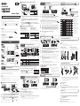 1
1
-
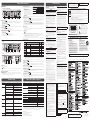 2
2


Yamaha MA2030 El manual del propietario
- Categoría
- Equipo de música suplementario
- Tipo
- El manual del propietario
- Este manual también es adecuado para
en otros idiomas
- français: Yamaha MA2030 Le manuel du propriétaire
- italiano: Yamaha MA2030 Manuale del proprietario
- English: Yamaha MA2030 Owner's manual
- Deutsch: Yamaha MA2030 Bedienungsanleitung
- русский: Yamaha MA2030 Инструкция по применению
- Nederlands: Yamaha MA2030 de handleiding
- português: Yamaha MA2030 Manual do proprietário
- dansk: Yamaha MA2030 Brugervejledning
- polski: Yamaha MA2030 Instrukcja obsługi
- čeština: Yamaha MA2030 Návod k obsluze
- svenska: Yamaha MA2030 Bruksanvisning
- Türkçe: Yamaha MA2030 El kitabı
- suomi: Yamaha MA2030 Omistajan opas
- română: Yamaha MA2030 Manualul proprietarului
Artículos relacionados
-
Yamaha MA2030a El manual del propietario
-
Yamaha MTX3 El manual del propietario
-
-
-
Yamaha MGP12X Manual de usuario
-
Yamaha MGP32X Manual de usuario
-
-
-
-