Troy-Bilt TB27 BC Manual de usuario
- Categoría
- Podadoras de césped
- Tipo
- Manual de usuario
Este manual también es adecuado para

769-13753 / 00 03/18
TB27BC
Electric Start Capable 2-Cycle Brushcutter / Trimmer
Operator’s Manual
IMPORTANT: Read this manual thoroughly before using this product. Follow all instructions.
SAVE THESE INSTRUCTIONS

2
TABLE OF CONTENTS
Service . . . . . . . . . . . . . . . . . . . . . . . . . . . . . . . . . . . . . . . . . . . . . .2
Safety . . . . . . . . . . . . . . . . . . . . . . . . . . . . . . . . . . . . . . . . . . . . . . .2
Know Your Unit . . . . . . . . . . . . . . . . . . . . . . . . . . . . . . . . . . . . . . . .6
Specifications . . . . . . . . . . . . . . . . . . . . . . . . . . . . . . . . . . . . . . . . .6
Assembly . . . . . . . . . . . . . . . . . . . . . . . . . . . . . . . . . . . . . . . . . . . . .7
Oil and Fuel . . . . . . . . . . . . . . . . . . . . . . . . . . . . . . . . . . . . . . . . . .13
Starting and Stopping . . . . . . . . . . . . . . . . . . . . . . . . . . . . . . . . . .14
Operation . . . . . . . . . . . . . . . . . . . . . . . . . . . . . . . . . . . . . . . . . . .16
Maintenance . . . . . . . . . . . . . . . . . . . . . . . . . . . . . . . . . . . . . . . . .18
Cleaning and Storage . . . . . . . . . . . . . . . . . . . . . . . . . . . . . . . . . .22
Troubleshooting . . . . . . . . . . . . . . . . . . . . . . . . . . . . . . . . . . . . . .23
Warranty . . . . . . . . . . . . . . . . . . . . . . . . . . . . . . . . . . . . . . . . . . . .24
SERVICE
All information, illustrations, and specifications in this manual are based
on the latest product information available at the time of printing. We
reserve the right to make changes at any time without notice.
The product may vary slightly from the illustrations contained in this
manual.
Copyright© 2018 MTD SOUTHWEST INC, All Rights Reserved.
SAFETY
SPARK ARRESTOR NOTE
NOTE: For users on U.S. Forest Land and in the states of
California, Maine, Oregon and Washington. All U.S. Forest Land
and the state of California (Public Resources Codes 4442 and
4443), Oregon and Washington require, by law that certain internal
combustion engines operated on forest brush and/or grass-covered
areas be equipped with a spark arrestor, maintained in effective
work
ing ord
er, or the engine be constructed, equipped and
maintained for the prevention of fire. Check with your state or local
authorities for regulations pertaining to these requirements. Failure
to follow these requirements could subject you to liability or a fine.
This unit is factory equipped with a spark arrestor. If it requires
replacement, contact your local service dealer to install the
appropriate
muff
ler assembly.
Read the operator’s manual and follow all warnings and safety
instructions. Failure to do so can result in serious injury to the
operator and/or bystanders.
SYMBOL MEANING
WARNING:
Signals a SERIOUS hazard.
Failure to obey a safety WARNING symbol CAN result in
serious injury to yourself or to others.
CAUTION:Signals a MODERATE hazard.
Failure to obey a safety CAUTION symbol MAY result in
property damage or injury to yourself or to others.
The purpose of safety symbols is to attract your attention to
possible dangers. The safety symbols, and their explanations,
deserve your careful attention and understanding. The safety
warnings do not by themselves eliminate any danger. The
instructions or warnings they give are not substitutes for proper
accident prevention measures.
NOTE: Advises you of information or instructions vital to the
operation or maintenance of the equipment.
DANGER:
Signals an EXTREME hazard.
Failure to obey a safety DANGER symbol WILL result in
serious injury or death to yourself or to others.
DO NOT RETURN THIS UNIT TO THE RETAILER. PROOF OF
PURCHASE WILL BE REQUIRED FOR WARRANTY SERVICE.
For assistance regarding the assembly, operation or maintenance of
the unit, please call 1-800-828-5500 (in the United States) or 1-800-
668-1238 (in Canada). Additional information can be found at
www.troybilt.com (in the United States) or www.troybilt.ca (in
Canada).
Warranty service is available through an aut
horized service center.
To
locate a service center in your area, please visit our website or
call the number listed above. Service on this unit, both within and
after the warranty period, should only be performed by an
authorized and approved service center. When servicing, use only
identical replacement parts.
WARNING:
This product can expose you to
chemicals including engine exhaust, which is known to the
State of California to cause cancer, and carbon monoxide,
which is known to the State of California to cause birth
defects or other reproductive harm. For more information
go to www.P65Warnings.ca.gov.

3
• IMPORTANT SAFETY INSTRUCTIONS •
READ ALL INSTRUCTIONS BEFORE OPERATING
• Read the instructions carefully. Be familiar with the controls and
proper use of the unit. Know how to stop the unit and disengage
the controls quickly.
• Stay alert. Do not operate this unit when tired, ill or under the
influence of alcohol, drugs or medication.
• Never allow children to operate the unit. Teens must be trained,
acco
mpanied and supervised by an adult. Never allow adults to
o
perate the unit without proper instruction.
• All guards and safety attachments must be installed properly
before operating the unit.
• Inspect the unit before use. Check for damaged parts. Check for
fuel leaks. Make sure all parts operate properly. Make sure all
fasteners are in place and secure. Make sure all moving parts are
properly aligned an
d are not bound. Replace parts that are cracked,
chipped, or damaged in any way. Have all damaged or improperly
working parts repaired or replaced by an authorized service center.
D
o not operate the unit with loose or damaged parts.
• Be aware of risk of injury to the head, hands and feet.
• Carefully inspect the area before starting the unit. Remove
rocks, broken glass, nails, wire, string and other obj
ects that
m
ay be thrown or become entangled with the unit.
• Clear the area of children, bystanders and pets; keep them
outside a 50-foot (15 m) radius, at a minimum. Even then, they are
still at risk from thrown objects. Encourage bystanders to wear
eye protection. If you are approached, stop the unit immediately.
• Squeeze the throttle control and check that it returns
automatically to the idle position.
Make all adjustments or
re
pairs before using the unit.
• Do not change the engine governor settings or overspeed the
engine.
• This unit is intended for occasional, household use only.
WARNING:
When using the unit, all safety
instructions must be followed. Please read these
instructions before operating the unit in order to ensure the
safety of the operator and any bystanders. Please keep
these instructions for later use.
SAFETY WARNINGS FOR GAS UNITS
• Store fuel only in containers specifically designed and approved
for the storage of such materials.
• Always stop the engine and allow it to cool before filling the
tank. Never remove the fuel tank cap or add fuel when the
engine is hot. Always loosen the fuel tank cap slowly to relieve
any pressure in the tank before fueling.
• Always mix and add fuel in a clean, well-ventil
ated outdoor are
a
where there are no sparks or flames. DO NOT smoke.
• Never operate the unit without the fuel cap securely in place.
• Avoid creating a source of ignition for spilled fuel. Wipe up any
spilled fuel from the unit immediately, before starting the unit.
Move the unit at least 30 ft. (9.1 m) from the fueling source and
site before starting the engine. DO NOT smoke.
• Never start or run the unit
inside a closed ro
om or building.
Breathing exhaust fumes can kill. Operate this unit only in a well
ventilated outdoor area.
WARNING:
Gasoline is highly flammable and
its vapors can explode if ignited. Take the following
precautions:
WHILE OPERATING
• Wear safety glasses or goggles that meet current ANSI / ISEA
Z87.1 standards and are marked as such. Wear ear/hearing
protection when operating this unit. Wear a face mask or dust
mask if the operation is dusty.
• Wear heavy long pants, boots, gloves and a long sleeve shirt. Do
not wear loose clothing, jewelry, short pants, sandals or go
barefoot. Secure hair above shoulder level.
• The cut
ting head / blade should re
main stationary when the
engine idles. If it does not, refer to Adjusting the Idle Speed.
• Adjust the handle to provide the best grip, if applicable.
• Make sure the cutting head / blade is not in contact with
anything before starting the unit.
• Use the unit only in daylight or good artificial light.
• Avoid accidental starting. Be in the starting position whenever
pulling the st
arter ro
pe. The operator and unit must be in a
stable position while starting. Refer to Starting and Stopping.
• Use the right tool. Only use this tool for its intended purpose.
Only use the unit as described in this manual.
• Always hold the unit with both hands when operating. Keep a
firm grip on both handles or grips.
• Do not overreach. Always keep proper footing and balance. Take
extra care when workin
g on stairs, steep slopes or inclines. To
a
void serious injury, do not operate the unit while on a ladder or
a roof.
• Keep hands, face, and feet away from all moving parts. Do not
touch or try to stop moving parts.
• Do not touch the engine, gear housing or muffler. These parts get
extremely hot from operation, even after the unit is turned off.
• Do not operate the unit faster than the speed needed to do t
he
j
ob. Do not run the unit at high speed when not in use.
• Do not force the unit. It will do a better, safer job when used at
the intended rate.
• Always turn the unit off when operation is delayed or when
carrying the unit from one location to another. Make sure all
moving parts come to a complete stop.

4
OTHER SAFETY WARNINGS
• Maintain the unit with care. Follow all maintenance instructions
in this manual.
• Do not perform maintenance procedures other than those
described in this manual. All service, other than the maintenance
procedures described in this manual, should be performed by an
authorized service dealer.
• Never remove, modify or make inoperative any safety device
furnished with the unit.
• Before
inspecting, maintaining, cleaning, storing, transporting or
re
placing any parts on the unit:
1. Stop the unit. Refer to Starting and Stopping.
2. Make sure all moving parts have stopped.
3. Allow the unit to cool.
4. Disconnect the spark plug wire.
• Secure the unit while transporting.
• Never store the unit with fuel in the tank, inside a building where
fumes may reach an open flame (pilot lights, etc.) or s
parks
(
switches, electrical motors, etc.).
• Store the unit in a dry place, secured or at a height to prevent
unauthorized use or damage. Keep the unit out of the reach of
children.
• Never douse or squirt the unit with water or any other liquid.
Keep handles dry and clean (free from debris, oil and grease).
Clean the unit after each use. Refer to Cleaning and Storage. Do
not use solvents or strong detergen
ts.
• K
eep these instructions. Refer to them often and use them to
instruct other users. If you loan this unit to others, also loan
them these instructions.
SAVE THESE INSTRUCTIONS
• Before setting the unit down, always make sure the engine is off
and all moving parts have stopped.
• If the unit strikes or becomes entangled with a foreign object,
stop the unit immediately. Check for damage. If damaged, do
not re
start or operate the unit until it is repaired. Do not operate
the unit with loose or damaged parts.
• Turn the engine off and disconnect the spark plug for
maintenance or repair.
• Use only original equipment manufacturer (OEM) replacement
parts and accessories for this unit. These are available from your
authorized service dealer. Use of any other parts or accessories
could lead to serious injury to t
he user,
or damage to the unit,
and void the warranty.
• Keep the unit clean. Carefully remove vegetation and other
debris that could block moving parts.
• To reduce fire hazard, replace a faulty muffler and spark arrestor.
Keep the engine and muffler free from grass, leaves, excessive
grease or carbon build up.
• If the unit starts to vibrate abnormally, stop the unit immediately.
Inspect the unit for the c
ause of the vibration. Vi
bration is
generally an indicator of trouble.
TRIMMER SAFETY
• Only use the trimming line described in the Specifications section
of this manual. Never use metal-reinforced line, wire, chain or
rope. These can break off and become dangerous projectiles.
• The cutting head shield must always be in place while operating
the unit.
• Do not operate the unit without both trimming lines ex
tended
a
nd the proper line installed. Do not extend the trimming line
beyond the length of the shield.
BRUSHCUTTER SAFETY
• The blade guard must always be in place while operating the unit.
• Always use the shoulder harness when operating a brushcutter.
• Always keep the handle between the operator and the blade
during operation.
• Never operate the unit with the blade above waist level.
• To avoid violent ki
ckback, do not attempt to cut material larg
er
than 1/2 inch (1.27 cm) in diameter.
• Blade thrust may occur when the spinning blade contacts an
object that it does not immediately cut. Blade thrust can be
violent enough to propel the unit and/or operator in any
direction, possibly causing a loss of control. Blade thrust can
occur without warning if the blade snags, stalls or binds. This is
more likely to
occur in are
as where it is difficult to see the
material being cut.
• The blade will continue to spin after the unit is turned off. A
coasting blade can cause serious injury. Maintain control of the
unit until all moving parts have stopped.
• Do not sharpen the blade. Sharpening the blade can cause the
tip of the blade to break off while in use. This can result in severe
personal injury. Replace the blade
if it is dull.
• D
o not operate the unit with a bent, cracked or dull blade.
Replace bent, cracked or dull blades.
• Do not use the blade for edging; severe personal injury to
yourself or others may occur.
• The blade may become very sharp from use. Always wear heavy
gloves when handling, replacing or cleaning the blade.

5
• SAFETY & INTERNATIONAL SYMBOLS •
This operator's manual describes safety and international symbols and pictographs that may appear on this product. Read the operator's
manual for complete safety, assembly, operating and maintenance and repair information.
SYMBOL MEANING SYMBOL MEANING
• SAFETY ALERT SYMBOL
Indicates danger, warning or caution. May be used in
conjunction with other symbols or pictographs.
• READ OPERATOR'S MANUAL
WARNING: Read the operator’s
manual(s) and follow all warnings and safety
instructions. Failure to do so can result in serious
injury to the operator and/or bystanders.
• WEAR EYE AND HEARING PROTECTION
WARNING:
Thrown objects and loud
noise can cause severe eye injury and hearing loss.
Wear eye protection meeting current ANSI / ISEA
Z87.1 standards and ear protection when operating
this unit. Use a full face shield when needed.
• WEAR FOOT PROTECTION
Always wear heavy-duty, non-slip footwear when
operating this unit.
• WEAR HAND PROTECTION
Always wear heavy-duty, non-slip gloves when
handling this unit.
• HANDLE POSITION
Move the handle until the arrow / line on the decal
touches the clamp assembly.
• UNLEADED FUEL
Always use clean, fresh unleaded fuel.
• OIL
Refer to operator’s manual for the proper type of oil.
• DO NOT USE E85 FUEL IN THIS UNIT
WARNING:
It has been proven that fuel
containing greater than 10% ethanol will likely
damage this engine and void the warranty.
• ON / OFF STOP CONTROL
ON / START / RUN
• ON / OFF STOP CONTROL
OFF or STOP
• PRIMER BULB
Push primer bulb, fully and slowly, 10 times.
• THROWN OBJECTS CAN CAUSE SEVERE INJURY
WARNING:
Small objects can be
propelled at high speed, causing injury.
• KEEP BYSTANDERS AWAY
WARNING:
Keep all bystanders,
especially children and pets, at least 50 feet (15 m)
from the operating area.
• HOT SURFACE
WARNING:Do not touch a hot muffler
or cylinder. You may get burned. These parts get
extremely hot from operation. When turned off, they
remain hot for a short time.
• SHARP BLADE
WARNING:There is a sharp blade on
the cutting head shield. To prevent serious injury, do
not touch the line cutting blade.
• BRUSHCUTTER: REPLACE DULL BLADE
WARNING:Do not sharpen the blade.
Sharpening the blade can cause the tip of the blade to
break off while in use. This can result in severe
personal injury. Replace the blade if it is dull.
• TRIMMER / BRUSHCUTTER SAFETY
WARNING:
Thrown objects and rotating
cutter can cause severe injury. Keep all bystanders,
especially children and pets, at least 50 feet (15 m)
from the operating area. The cutting head shield must
be installed when using a trimmer attachment. The
blade shield must be installed when using the
brushcutter attachment.

Brush Blade
Guard
Fuel Cap
Handle
Blade
Shaft Grip
Upper Shaft
Housing
Starter
Rope Grip
Throttle Control
Spark Plug
Muffler
On/Off Switch
Air Filter Cover
Coupler
Throttle Lockout
Lower Shaft
Housing
Shoulder Strap
/ Harness Loop
Electric Start Port
Choke Lever
Primer Bulb
Cutting Head
Cutting Head
Shield
Hanger Cap
6
SPECIFICATIONS*
* All specifications are based on the latest product information available at the time of printing. We reserve the right to make changes at any
time without notice.
KNOW YOUR UNIT
Engine Type . . . . . . . . . . . . . . . . . . . . . . . . . . . . . . . . . . . . . . . . . . . . . . . . . . . . . . . . . . . . . . . . . . . . . . . . . . . . . . . . . . . . . . . Air-Cooled, 2-Cycle
Displacement. . . . . . . . . . . . . . . . . . . . . . . . . . . . . . . . . . . . . . . . . . . . . . . . . . . . . . . . . . . . . . . . . . . . . . . . . . . . . . . . . . . . . . . 27 cc (1.64 cu. in.)
Spark Plug Gap. . . . . . . . . . . . . . . . . . . . . . . . . . . . . . . . . . . . . . . . . . . . . . . . . . . . . . . . . . . . . . . . . . . . . . . . . . . . . . . . . . . . 0.025 in. (0.635 mm)
Spark Plug. . . . . . . . . . . . . . . . . . . . . . . . . . . . . . . . . . . . . . . . . . . . . . . . . . . . . . . . . . . . . . . . . . . . . . . . . . Champion® RDJ7J or equivalent plug
Lubrication . . . . . . . . . . . . . . . . . . . . . . . . . . . . . . . . . . . . . . . . . . . . . . . . . . . . . . . . . . . . . . . . . . . . . . . . . . . . . . . . . . . . . . . . . . . Fuel/Oil Mixture
Fuel/Oil Ratio . . . . . . . . . . . . . . . . . . . . . . . . . . . . . . . . . . . . . . . . . . . . . . . . . . . . . . . . . . . . . . . . . . . . . . . . . . . . . . . . . . . . . . . . . . . . . . . . . . 40:1
Fuel Tank Capacity . . . . . . . . . . . . . . . . . . . . . . . . . . . . . . . . . . . . . . . . . . . . . . . . . . . . . . . . . . . . . . . . . . . . . . . . . . . . . . . . . . . . . . 14 oz. (414 ml)
Approximate Unit Weight (No fuel) . . . . . . . . . . . . . . . . . . . . . . . . . . . . . . . . . . . . . . . . . . . . . . . . . . . . . . . . . . . . . . . . 13 - 14.5 lbs. (5.9 - 6.6 kg)
Trimmer Mechanism . . . . . . . . . . . . . . . . . . . . . . . . . . . . . . . . . . . . . . . . . . . . . . . . . . . . . . . . . . . . . . . . . . . . . . . . . . . . . . . . . . . . . . . Bump Head
Trimming Line Diameter . . . . . . . . . . . . . . . . . . . . . . . . . . . . . . . . . . . . . . . . . . . . . . . . . . . . . . . . . . . . . . . . . . . . . . . . . . . 0.105 inches (2.67 mm)
Cutting Path Diameter (Tr
immer). . . . . . . . . . . . . . . . . . . . . . . . . . . . . . . . . . . . . . . . . . . . . . . . . . . . . . . . . . . . . . . .
. . . . . . . . . . . 18 in. (45.7 cm)
Cutting Path Diameter (Brushcutter) . . . . . . . . . . . . . . . . . . . . . . . . . . . . . . . . . . . . . . . . . . . . . . . . . . . . . . . . . . . . . . . . . . . . . . . . . 8 in. (20.3 cm)
APPLICATIONS
As a trimmer:
• Cutting grass and light weeds
• Edging
• Decorative trimming around trees, fences, etc.
As a brushcutter:
• Cutting weeds and light brush up to 1/2 inch (1.27 cm) in
diameter
Other optional attachments may be used with this unit.
ASSEMBLY TOOLS REQUIRED
• Phillips Screwdriver

7
ASSEMBLY
Fig. 1
Knob
Tighten
Loosen
Fig. 3
Fig. 2
Coupler
Attachment
Release Button
Guide Recess
Primary Hole
INSTALLING AND REMOVING THE ATTACHMENT
The coupler enables the use of various optional attachments.
Installing the Attachment
1. Remove the hanger cap from the attachment. Keep the hanger
cap for use when storing the attachment. If present, remove the
gray spacer from the coupler.
2. Set the unit on a flat, level surface.
3. Turn the knob counterclockwise to loosen the coupler (Fig. 1).
4. Align the release b
utton with the guide re
cess (Fig. 3).
5. Push the attachment straight into the coupler (Fig. 2) until the
release button snaps firmly into the primary hole (Fig. 3).
6. Turn the knob clockwise to tighten the coupler (Fig. 1).
Removing the Attachment
1. Set the unit on a flat, level surface.
2. Turn the knob counterclockwise to loosen the coupler (Fig. 1).
3. Press and hold the release button (Fig. 3).
4. Pull t
he attachment straight out of the coupler (Fig. 2).
WARNING:
Before operating the unit, make sure the
release button is fully snapped into the primary hole and the
knob is securely tightened.
WARNING:
Unless specified otherwise, the release
button should be snapped into the primary hole only. Using
the wrong hole could lead to personal injury or damage to
the unit.
WARNING:
Before using any attachment, read and
understand the manual that came with the attachment.
Follow all safety information contained within.
WARNING:
To avoid serious personal injury and
damage to the unit, shut the unit off before removing or
installing an attachment.

8
INSTALLING AND ADJUSTING THE HANDLE
Installing the Handle
1. Place the handle between the top clamp and middle clamp (Fig. 4).
If necessary, rotate or flip the middle clamp until the holes in the top
clamp and middle clamp align.
2. Place the clamps and handle over the upper shaft housing and
onto the bottom clamp (Fig. 4).
NOTE: Make sure the curved portion of the handle is on the
operator's left (Fig. 4).
3. While holding the pieces together, insert the bolts (x4) into the
aligned holes (Fig. 4).
4
. Screw a nut onto the end of a bolt, but only slightly. Push the nut
into the hexagonal recess on the bottom clamp. Hold the nut in
place with a finger to keep it in the recess. Tighten the bolt with
a Phillips screwdriver, but do not tighten it completely (Fig. 4).
Repeat this step for each nut and bolt.
5. Hol
d the unit in the operating position (Fig. 22) and slide the
h
andle in or out of the clamp until the arrow/line on the decal
touches the clamp (Fig. 5).
6. Angle the handle forward or backward, as desired.
7. Tighten the bolts with a Phillips screwdriver until the handle is
secure.
Adjusting the Handle
If the handle requires adjustment:
1. Loosen the bolts (x4) slightly with a Phillips screwdriver (Fig. 4).
2
. H
old the unit in the operating position (Fig. 22) and angle the
handle forward or backward, as desired.
3. Tighten the bolts with a Phillips screwdriver until the handle is
secure.
Fig. 4
Bottom Clamp
Handle
Upper Shaft
Housing
Nuts (x4)
Bolts (x4)
Fig. 5
Middle
Clamp
Top Clamp
Clamp

9
Fig. 6
Strap
Buckle
Clip
Fig. 7
Clip
Fig. 8
Strap
Buckle
Center
Slot
Lower Slot
ASSEMBLING AND USING THE SHOULDER STRAP
Assembling the Shoulder Strap
1. Push the strap up through the center slot in the buckle (Fig. 6).
2. Bend the strap over and push it down through the lower slot in
the buckle (Fig. 6).
Using the Shoulder Strap
1. Put the shoulder strap over the operator’s head and onto the left
shoulder.
2. Start the unit. Refer to Starting and Stopping.
3. Snap the clip onto the should
er strap / harn
ess loop (Fig. 7).
4. Adjust the shoulder strap to fit the operator (Fig. 8). Pull the
buckle up to loosen the shoulder strap. Pull the strap down to
tighten the shoulder strap.
WARNING:
To avoid serious personal injury, always use
the shoulder strap when operating the unit as a brushcutter.
Shoulder Strap
/ Harness Loop

10
CONVERTING THE UNIT FROM A BRUSHCUTTER TO A
TRIMMER
Removing the Blade
1. Rotate the blade (Fig. 11) until the shaft bushing hole aligns with
the locking rod slot (Fig. 9).
2. Insert the locking rod through the locking rod slot and into the
shaft bushing hole (Fig. 9).
3. Hold the locking rod in place by grasping the other end against
the shaft housing (Fig. 10).
4. While holding the locking rod in place, un
screw the nut by turning
it clockwise with a wrench (Fig. 10).
5
. Remove the locking rod (Fig. 11).
6. Remove the blade retainer and blade (Fig. 11).
Installing the Cutting Head
1. Rotate the output shaft bushing until the shaft bushing hole
aligns with the locking rod slot (Fig. 9).
2. Insert the locking rod through the locking rod slot and into the
shaft bushing hole (Fig. 9).
3. Hold the locking rod in place
by grasping the other end against
the shaft housing (Fig. 10).
4. While holding the locking rod in place, put the blade retainer on
the output shaft with the flat surface against the output shaft
bushing (Fig. 12).
5. Screw the cutting head counterclockwise onto the output shaft
(Fig. 12). Tighten the cutting head securely.
6. Remove the locking rod.
7. Install the cutting head shield. Refer to Installing an
d Removing
t
he Cutting Head Shield.
WARNING:
To avoid serious personal injury, always
wear gloves when handling the blade.
Fig. 9
Fig. 11
Shaft Bushing Hole
Blade Retainer
Output Shaft
Bushing
Locking Rod
Locking Rod Slot
Nut
Blade
Locking Rod
Fig. 10
Shaft Housing
Fig. 12
Blade Retainer
Output Shaft
Output Shaft
Bushing
Cutting Head
Nut
WARNING:
To avoid serious personal injury or damage
to the unit, do not start or operate the unit with the locking
rod inserted into the locking rod slot.
WARNING:
To avoid serious personal injury, always stop
the engine and allow the unit to cool before installing or
removing any parts. Never install or remove parts while the
unit is running. Disconnect the spark plug wire to prevent
the unit from starting accidentally.

11
CONVERTING THE UNIT FROM A TRIMMER TO A
BRUSHCUTTER
Removing the Cutting Head
1. Remove the cutting head shield. Refer to Installing and
Removing the Cutting Head Shield.
2. Rotate the cutting head (Fig. 14) until the shaft bushing hole
aligns with the locking rod slot (Fig. 9).
3. Insert the locking rod through the locking rod slot and into the
shaft bushing hole (Fig. 9).
4. Hold the locking rod in place b
y grasping the other end against
t
he shaft housing (Fig. 13).
5. While holding the locking rod in place, unscrew the cutting head
by turning it clockwise (Fig. 14).
6. Remove the locking rod (Fig. 14).
7. Remove the blade retainer (Fig. 14).
Installing the Blade
1. Rotate the output shaft bushing until the shaft bushing hole
aligns with the locking rod slot (Fig. 9).
2. Insert the locking rod through the lockin
g rod slot and into the
shaft bushing hole (Fig. 9).
3. Hold the locking rod in place by grasping the other end against
the shaft housing (Fig. 13).
4. While holding the locking rod in place, put the blade on the
output shaft bushing (Fig. 15).
5. Place the blade retainer on the output shaft with the flat surface
against the blade (Fig. 15).
6. Screw the nut onto the output shaft (Fig. 15).
7. Tighten the nut c
ounterc
lockwise with a wrench (Fig. 16):
• If using a torque wrench, torque to: 325 - 335 in•lb, 27 - 28
ft.•lb, 37 - 38 N•m.
• If using a closed-end or socket wrench, turn the nut until the
blade retainer is snug against the blade. Make sure the blade
is installed correctly, then rotate the nut an additional 1/4 to
1/2 turn counterclockwise.
8. Remove the locking rod.
WARNING:
To avoid serious personal injury, always
wear gloves when handling the blade.
Fig. 15
Blade Retainer
Nut
Blade
Output Shaft
Bushing
Locking Rod
Pilot Hole
Fig. 16
Fig. 13
Shaft Housing
Fig. 14
Blade Retainer
Cutting Head
Locking Rod
Output Shaft
WARNING:
To avoid serious personal injury, make sure
that the pilot hole on the blade is sitting flat against the
output shaft bushing (Fig. 15). The unit will vibrate and the
blade may fly off if the blade is not centered.
WARNING:
To avoid serious personal injury or damage
to the unit, do not start or operate the unit with the locking
rod inserted into the locking rod slot.
WARNING:
To avoid serious personal injury, always stop
the engine and allow the unit to cool before installing or
removing any parts. Never install or remove parts while the
unit is running. Disconnect the spark plug wire to prevent
the unit from starting accidentally.

12
INSTALLING AND REMOVING THE CUTTING HEAD SHIELD
Installing the Cutting Head Shield
1. Place the cutting head shield over the shield mount surface on
the brush blade guard (Fig. 17).
2. Insert the screws (x3) through the screw holes on the cutting
head shield (Fig. 17).
3. Tighten the screws with a Phillips screwdriver.
Removing the Cutting Head Shield
1. Unscrew the screws (x3) on the cutting head shield wi
th a
P
hillips screwdriver (Fig. 17).
2. Store the parts for future use.
WARNING:
DO NOT install the cutting head shield when
operating the unit as a brushcutter. Remove the cutting
head shield before removing or installing the blade.
Fig. 17
Brush Blade
Guard
Cutting Head
Shield
Screws (x3)
Shield Mount
WARNING:
To prevent serious personal injury, when
using the unit as a trimmer, never operate the unit without
the cutting head shield in place.

13
OIL AND FUEL
FUELING THE UNIT
1. Position the unit with the fuel cap facing up.
2. Slowly remove the fuel cap.
3. Place the fuel container spout into the fuel tank fill hole and fill
the tank.
NOTE: Do not overfill the tank.
4. Wipe up any fuel that may have spilled.
5. Reinstall the fuel cap.
6. Move the unit at least 30 ft. (9.1 m) from the fuel container and
the fueling site before starting the engine.
OIL AND FUEL MIXING INSTRUCTIONS
The use of old and/or improperly mixed fuel is the most common cause
of performance problems. Use only fresh, clean unleaded gasoline.
Follow the instructions carefully for the proper gasoline/oil mixture.
Definition of Blended Fuels
Today's fuels are often a blend of gasoline and oxygenates such as
ethanol, methanol or MTBE (ether). Alcohol-blended fuel absorbs
water. As little a
s 1% water in the fuel can make fuel and oil
s
eparate, forming acids when stored. ALWAYS use fresh fuel (less
than 30 days old).
NOTE: Dispose of old fuel according to federal, state and local
regulations.
Using Blended Fuels
If using a blended fuel:
• Always use the fresh fuel mix explained in this operator's manual
• Use the fuel additive STA-BIL® or an equivalent
• Always agitate the fuel mix before fueling
the unit
U
sing Fuel Additives
The container of 2-cycle oil provided with this unit includes a fuel
additive to help inhibit corrosion and minimize gum deposits.
Always use the brand of 2-cycle oil that came with this unit. If this is
unavailable, use a 2-cycle oil designed for air-cooled engines and
mix it with a fuel additive, such as STA-BIL Fuel Stabilizer or an
equivalent. Add 0.8 oz. (23 ml) of fuel additive per gallon of fuel,
a
ccording to the instructions on the container. NEVER add fuel
additives directly to the unit's fuel tank.
Mixing the Fuel
NOTE: This unit comes with a 3.2 oz. (95 ml) container of 2-cycle
oil. To obtain the correct fuel mixture described below, pour the
entire container into one gallon of unleaded gasoline.
Thoroughly mix the proper ratio of unleaded gasoline with 2-cycle
eng
ine oil. Do not mix them dire
ctly in the unit’s fuel tank. Use a
separate fuel can. Use a 40:1 gasoline/oil ratio. See the table below
for specific gasoline and oil mixing ratios.
Unleaded gasoline 2-cycle oil
1 gallon U.S.
(3.8 liters)
3.2 fl. oz.
(95 ml)
1 liter 25 ml
MIXING RATIO - 40:1
CAUTION:
For proper engine operation and maximum
reliability, pay strict attention to the gasoline and oil mixing
instructions on the 2-cycle oil container. Using improperly
mixed fuel can severely damage the engine.
WARNING:
Gasoline is extremely flammable. Ignited
vapors may explode. Always stop the engine and allow it
to cool before filling the fuel tank. Do not smoke while
filling the tank. Keep sparks and open flames at a distance
from the area.
WARNING:
Remove the fuel cap slowly to avoid injury
from fuel spray. Never operate the unit without the fuel cap
securely in place.
WARNING:
Add fuel in a clean, well-ventilated outdoor
area. Wipe up any spilled fuel immediately. Avoid creating
a source of ignition for spilled fuel. Do not start the engine
until fuel vapors dissipate.
CAUTION:
DO NOT USE E85 FUEL IN THIS UNIT. It
has been proven that fuel containing greater than 10%
ethanol will likely damage this engine and void the warranty.

14
STARTING AND STOPPING
WARNING:
Operate this unit only in a well-ventilated
outdoor area. Carbon monoxide exhaust fumes can be
lethal in a confined area.
WARNING:
Avoid accidentally starting the unit. To avoid
serious injury, the operator and the unit must be in a stable
position when pulling the starter rope (Fig. 20).
STOPPING INSTRUCTIONS
1. Release the throttle control and allow the engine to idle.
2. Press and hold the On/Off switch in the Off (O) position until the
engine comes to a complete stop (Fig. 18).
STARTING INSTRUCTIONS
NOTE: To prevent the throttle control from being squeezed
accidentally, this unit has a throttle lockout. The throttle control
cannot be squeezed unless the throttle lockout is also engaged.
NOTE: T
here is no need to turn the unit on. The On/Off switch is in
the On ( I ) position at all times (Fig. 18).
Before Starting the Unit
1. Mix gasoline with oil. Refer to Oil and Fuel Mixing Instructions.
2. Fill the fuel tank. Refer to Fueling the Unit.
3. Put the shoulder strap over the operator’s head and onto the left
shoulder.
Starting the Unit
NOTE: DO NOT squeeze the throttle control (Fig. 18) until st
ep 6.
1
. Slowly press and release the primer bulb 10 times (Fig. 19).
2. Flip the choke lever clockwise until it clicks (Fig. 19).
3. Crouch in the starting position (Fig. 20).
4. Pull the starter rope with a controlled and steady motion until the
unit starts (Fig. 20).
5. Idle the engine for 30 seconds.
6. Press and hold the throttle lockout (Fig. 18). Squeeze the throttle
control as needed for operation (Fig
. 18).
I
F... the engine does not start after pulling the starter rope 10 times,
repeat the starting procedure.
IF... the engine is already warm: Press and hold the throttle lockout.
Squeeze and hold the throttle control. Pull the starter rope with a
controlled and steady motion until the unit starts.
After Starting the Unit
1. Snap the shoulder strap clip onto the shoulder strap / harness
loop. Adjust the sh
oulder strap to fit the operator.
Refer to
Assembling and Using the Shoulder Strap.
Fig. 20
Starting
Position
Starter Rope Grip
Fig. 19
Choke Lever
Fig. 18
Throttle Control
Throttle
Lockout
On/Off Switch
(I = On / O = Off)
Primer Bulb

15
STOPPING INSTRUCTIONS
1. Release the throttle control and allow the engine to idle.
2. Press and hold the On/Off switch in the Off (O) position until the
engine comes to a complete stop (Fig. 18).
This unit can be started with an optional electric start accessory
(items sold separately). Refer to the electric start accessory
operator’s manual for the proper use of this feature.
Please contact your local retailer,
call the Customer Support
Department or visit our website for more information.
USING THE ELECTRIC START ACCESSORY
STARTING INSTRUCTIONS
NOTE: To prevent the throttle control from being squeezed
accidentally, this unit has a throttle lockout. The throttle control
cannot be squeezed unless the throttle lockout is also engaged.
NOTE: There is no need to turn the unit on. The On/Off switch is in
the On ( I ) position at all times (Fig. 18).
Before Starting the Unit
1. Mix gasoline with oil.
Refer to Oil and Fuel Mixing Instructions.
2
. Fill the fuel tank. Refer to Fueling the Unit.
3. Put the shoulder strap over the operator’s head and onto the left
shoulder.
Starting the Unit
Read the Operator's Manual that came with the electric start
accessory before attempting these instructions.
NOTE: DO NOT squeeze the throttle control (Fig. 18) until step 8.
1. Slowly press and release the primer bulb 10
times (
Fig. 19).
2. Flip the choke lever clockwise until it clicks (Fig. 19).
3. Crouch in the starting position (Fig. 20).
4. Insert the electric start accessory into the electric start port (Fig. 21).
5. Run the electric start accessory in intervals no longer than 2
seconds each until the unit starts.
6. Remove the electric start accessory from the unit, unless specified
otherwise in the electric start ac
cessory Operator's Manual.
7
. Idle the engine for 30 seconds.
8. Press and hold the throttle lockout (Fig. 18). Squeeze the throttle
control as needed for operation (Fig. 18).
IF... the engine does not start after running the electric start
accessory for 10 intervals, repeat the starting procedure.
IF... the engine is already warm: Insert the electric start accessory into
the electric start port. Press and h
old the throttle lockout. Squeeze
and hold the throttle control. Run the electric start accessory in
intervals no longer than 2 seconds each until the unit starts.
Remove the electric start accessory from the unit, unless specified
otherwise in the electric start accessory Operator's Manual.
A
fter Starting the Unit
1. Snap the shoulder strap clip onto the shoulder strap / harness
loop. Adjust the shoulder
strap to fit the operator.
Refer to
Assembling and Using the Shoulder Strap.
Fig. 21
Electric Start
Port

16
OPERATION
HOLDING THE UNIT
• Stand in the operating position (Fig. 22). Stand up straight. Do
not bend over.
• Keep feet apart and firmly planted.
• Hold the shaft grip with the right hand. Keep the right arm
slightly bent.
• Hold the handle with the left hand. Keep the left arm straight.
• Hold the unit at waist level.
• Position the cutting head / blade a few inches above the ground.
WARNING:
Always wear eye, hearing, hand, foot and
body protection to reduce the risk of injury when operating
this unit.
WARNING:
To prevent serious personal injury, avoid arm
contact with the engine while operating the unit. The
engine may be extremely hot.
Fig. 22
TIPS FOR BEST RESULTS (AS A BRUSHCUTTER)
• Keep the blade parallel to the ground.
• Always cut with the unit running at full speed. This provides
maximum cutting power and makes the blade less likely to bind,
stall or cause blade thrust.
• To direct clippings away from the operator, cut from left to right
whenever possible.
• Always release the throttle control and allow the unit to idle
when not cutt
ing.
• W
hen finished, always unsnap the shoulder strap from the unit
before taking off the shoulder strap.
• Never use a dull blade. If the blade becomes dull, refer to
Maintaining the Blade in the Maintenance section.
WARNING:
To avoid serious injury to the operator or
others, do not use the blade as an edger.
WARNING:
Blade thrust can occur when the spinning
blade contacts an object that it does not immediately cut.
Blade thrust can be violent enough to cause the unit
and/or operator to be propelled in any direction and
possibly lose control of the unit. Blade thrust can occur
without warning if the blade snags, stalls or binds. This is
more likely to occur in areas where it is difficult to see the
material be
ing cut.
WARNING:
The blade will continue to spin for a while
after the unit is turned off. To avoid serious personal injury,
do not touch a coasting blade.
WARNING:
To avoid serious personal injury, always turn
the unit off before removing debris from the unit. Allow the
blade to come to a complete stop.

17
DECORATIVE TRIMMING (AS A TRIMMER)
When trimming around trees, posts, fences, etc., rotate the whole
unit so that the cutting head is at a 30° angle to the ground (Fig. 24).
Fig. 24
TIPS FOR BEST RESULTS (AS A TRIMMER)
• For most operations, cut from side to side.
• To direct clippings away from the operator, tilt the cutting head
slightly down to the right; cut from left to right whenever possible.
• Cut tall grass (over 8 inches (20cm)) from the top down by
lowering the cutting head onto the grass.
• Cut with the tip of the trimming line.
• Cut in small increments. Move slowly.
Do not forc
e the unit.
• Do not trim wet grass or weeds.
NOTE: Some line breakage will occur from:
• Entanglement with foreign matter
• Normal line fatigue
• Attempting to cut thick vegetation
• Forcing the line into objects such as walls or fence posts
ADJUSTING THE TRIMMING LINE LENGTH
This unit is equipped with a bump head. Trimming line can be
released from the cutting head without stopping the engine.
To release more line, lightly tap the bump knob on the ground (Fig. 23)
w
hile operating the unit at high speed. For best results, tap the
bump knob on bare ground or hard soil. Attempting to release line in
tall grass may stall the engine.
NOTE: Do not rest the cutting head on the ground while the unit is
running.
Each time the bump knob is tapped, about 1 inch (25.4 mm) of
trimming line is released.
NOTE: Alwa
ys keep the trimming line fully extended. Line re
lease
becomes more difficult when the cutting line gets shorter.
A blade in the cutting head shield will cut the line to the proper
length if any excess line is released.
WARNING:
Do not remove or alter the line cutting blade
assembly. Excessive line length will make the unit
overheat. This may lead to serious personal injury or
damage to the unit.
Fig. 23
Bump Knob

18
EDGING (AS A TRIMMER)
The trimmer attachment can be used for edging (Fig. 25). Alternatively,
a bladed lawn edger attachment can also be purchased for use with
this unit.
Rotating the Trimmer Attachment
When edging around sidewalks, flowerbeds, etc., rotate the trimmer
attachment 90° inside the coupler. DO NOT rotate the entire unit 90°.
1. Turn the knob counterclockwise to loosen the coupler (Fig. 26).
2. P
ress and hold the release button (Fig. 26).
3. Rotate the attachment until the release button snaps firmly into
the 90° edging hole (Fig. 26).
4. Turn the knob clockwise to tighten the coupler (Fig. 26).
Maintaining the Trimming Line
Hard surfaces, such as sidewalks, can cause the trimming line to
wear down quickly or break.
• Frequently check and adjust the trimming line length. Refer to
Adjusting the Tri
mming Line Length. Always keep the trimming
l
ine fully extended.
• DO NOT force the unit. Make shallow cuts in as many passes as are
necessary to achieve the desired depth. Cut at a slow, even pace.
Fig. 25
WARNING:
Only snap the release button into the 90°
edging hole when edging with the trimmer attachment.
Using the 90° edging hole with other attachments could
lead to personal injury or damage to the unit.
WARNING:
To avoid serious personal injury and
damage to the unit, shut the unit off before rotating the
attachment.
Fig. 26
Release Button
90˚ Edging Hole
Knob
MAINTENANCE SCHEDULE
Perform these required maintenance procedures at the frequency
stated in the table. These procedures should also be a part of any
seasonal tune-up.
NOTE: Some maintenance procedures may require special tools or
skills. If you are unsure about these procedures, take the unit to
an MTD authorized service dealer.
NOTE: Maintenance, replacement, or repair of the emission control
devices and
system may be performed by an MTD authorized
s
ervice dealer.
NOTE: Please read the California/EPA statement that came with the
unit for a complete listing of terms and coverage for the emissions
control devices, such as the spark arrestor, muffler, carburetor, etc.
MAINTENANCE
FREQUENCY MAINTENANCE REQUIRED
Every 10 hours • Clean and re-oil the air filter. Refer to
Maintaining the Air Filter.
Every 25 hours • Check the spark plug condition and gap.
Refer to Maintaining the Spark Plug.
WARNING:
To avoid serious personal injury, always stop
the engine and allow it to cool before cleaning or maintaining
the unit. Never perform cleaning or maintenance while the
unit is running. Disconnect the spark plug wire to prevent
the unit from starting accidentally.
WARNING:
Wear protective clothing and observe all
safety instructions to prevent serious personal injury.

19
REPLACING THE TRIMMING LINE
Only use the trimming line described in the Specifications section.
Other types of trimming line may cause the unit to overheat or fail.
NOTE: Always use the correct line length when installing trimming
line. The line may not release properly if the line is too long.
Part 1 - Removing the Inner Reel
1. Hold the cutting head in place (Fig. 27). Turn the bump knob
clockwise to unscre
w it from the cutting head (Fig. 27).
NOTE: The outer spool (Fig. 28) will remain attached to the unit.
2. Inspect the bolt inside the bump knob to make sure it moves
freely (Fig. 27). Replace the bump knob if it is damaged.
3. Remove the inner reel from the outer spool (Fig. 28).
4. Remove the spring from the inner reel (Fig. 28).
5. Use a clean cloth to clean the inner reel, spring, arbor and inner
surf
ace of the outer spool.
6. Check the indexing teeth and holding slots for wear (Fig. 29). If
necessary, remove burrs or replace the inner reel and outer spool.
P
roceed to Part 2 - Winding New Trimming Line onto the Inner Reel.
Part 2 - Winding New Trimming Line onto the Inner Reel
• If using single line, refer to Winding Single Line.
• If using split line, refer to Winding Split Line.
• If using a prewound i
nner re
el, proceed to Part 3 - Installing the
Inner Reel.
Winding Single Line
1. Cut one 18-foot (5.5 m) length of new single trimming line. Fold
the line in half to create a loop in the middle.
2. Insert the two line ends through the two holes in the inner reel (Fig.
30). Pull the line through the inner reel so that the loop is as small
as possible (Fig. 30). Make sure the line ends are of equal length.
3. W
ind the line tightly in the dire
ction shown on the bottom of the
inner reel until about 6 inches (150 mm) of line remains. Place
your index finger between the two lines to stop the lines from
overlapping.
NOTE: Failure to wind the line in the direction indicated will cause
the cutting head to operate incorrectly.
4. Insert the two 6-inch ends into the two holding slots (Fig. 31).
Proceed to Part 3 - Install
ing the Inner Reel.
W
inding Split Line
1. Cut one 9-foot (2.7 m) length of new split line trimming line.
2. Insert one line end through one of the two holes in the inner reel.
Pull the line through the inner reel until about 4 inches (10 cm)
remain (Fig. 32).
3. Insert the end of the 4-inch section into the open hole in the
inner reel and pull the line tight to make the loop as small as
possible (Fig. 32).
4.
Split the other line end about 6 inches (150 mm).
5
. Wind the line tight in even layers in the direction indicated on the
inner reel.
NOTE: Failure to wind the line in the direction indicated will cause
the cutting head to operate incorrectly.
6. Insert the two 6-inch ends into the two holding slots (Fig. 31).
Proceed to Part 3 - Installing the Inner Reel.
WARNING:
Never use metal-reinforced line, wire, chain or
rope. These can break off and become dangerous projectiles.
Fig. 28
Outer Spool
Spring
Inner Reel
Arbor
Fig. 27
Bolt
Bump Knob
Cutting Head
Arbor
Fig. 30
Loop
Fig. 29
Indexing Teeth
Holding Slots

20
Part 3 - Installing the Inner Reel
1. Pass the two line ends through the eyelets in the outer spool
(Fig. 33).
2. Place the spring inside the inner reel (Fig. 33).
3. Insert the inner reel into the outer spool (Fig. 33). Push the inner
reel and outer spool together.
4. While holding the inner reel and outer spool together, firmly pull
the two line ends to release them from the holding slots.
5. While hold
ing the inner re
el and outer spool together, screw the
bump knob on counterclockwise (Fig. 27). Tighten the bump
knob securely.
Fig. 32
Fig. 31
Holding
Slots
Fig. 33
Outer Spool
Inner Reel
Spring
Eyelets
MAINTAINING THE BLADE
The blade has a second cutting edge. If the blade becomes dull,
remove the blade, turn it upside down and reinstall the blade. If both
sides are dull, replace the blade. Refer to Removing the Blade and
Installing the Blade in the Assembly section.
WARNING:
Do not sharpen the blade. Sharpening the
blade can cause the blade tip to break off while in use.
This can result in severe personal injury.

21
ADJUSTING THE IDLE SPEED
If the engine will not idle properly:
1. Start the engine. Refer to Starting and Stopping.
2. Release the throttle control and let the engine idle.
NOTE: Make sure the choke lever is NOT engaged while adjusting
the idle speed.
• If the engine stops, increase the idle speed. Use a small
Phillips screwdriver to turn the idle speed screw clockwise,
1/8 of a turn at a time, until the eng
ine idles smoothly (Fig. 36).
• I
f the cutting head spins when the engine idles, reduce the idle
speed. Turn the idle speed screw counterclockwise, 1/8 of a
turn at a time, until the cutting head stops moving (Fig. 36).
WARNING:
The cutting head may spin during idle speed
adjustments. Wear protective clothing and observe all
safety instructions to prevent serious personal injury.
MAINTAINING THE AIR FILTER
Failure to maintain the air filter can result in poor performance or can
cause permanent damage to the engine. Engine failure due to
improper air filter maintenance is not covered by the product warranty.
Cleaning the Air Filter
1. Open the air filter cover by unscrewing the cover screw (Fig. 34).
2. Remove the air filter from the air filter housing (Fig. 34).
3. Wash the air filt
er in deterg
ent and water. Rinse the air filter
thoroughly and allow it to dry.
4. Lightly coat the air filter with clean SAE 30 oil.
5. Squeeze the air filter to spread and remove excess oil.
6. Reinstall the air filter in the air filter housing (Fig. 34).
NOTE: Operating the unit without the air filter and air filter cover will
VOID the warranty.
7. Insert the hooks on the air filter housing into the slots
on the air
f
ilter cover (Fig. 35).
8. Swing the air filter cover to the right and align the cover screw
with the cover screw hole (Fig. 35). Tighten the cover screw to
secure the air filter cover.
NOTE: Do not over tighten as this may strip the screw.
Fig. 34
Fig. 35
Hooks
Air Filter
Cover
Air Filter
Air Filter
Housing
Air Filter Cover
Cover Screw
Cover
Screw Hole
Air Filter
Housing
Slots
Fig. 36
Idle Speed Screw

22
CLEANING AND STORAGE
CLEANING
Use a small brush to clean the outside of the unit. Do not use strong
detergents. Household cleaners that contain aromatic oils such as
pine and lemon, and solvents such as kerosene, can damage
plastic. Wipe off any moisture with a soft cloth.
Clean the brushcutter blade with a household cleaner to remove
gum buildup. Wipe the brushcutter blade with a light machine oil to
pre
vent rust.
STORAGE
• Never store a fueled unit where fumes may reach an open flame
or spark.
• Allow the engine to cool before storing.
• Lock up the unit to prevent unauthorized use or damage.
• Store the unit in a dry, well-ventilated area.
• Store the unit out of the reach of children.
• To suspend the attachment from a hook, install the hanger cap
onto the attachment. Make sure the release button is securely
locked into one of the holes on the hanger cap.
S
hort-term Storage (1-2 weeks)
1. Store the unit in a horizontal position. If this is not possible, store
the unit vertically with the engine at the top.
Long-term Storage
1. Remove the fuel cap, tip the unit and drain the fuel into an
approved container. Reinstall the fuel cap.
2. Start the engine and allow it to run until it stalls. This ensures
that all fuel
has been drained fro
m the carburetor.
3. Allow the engine to cool. Remove the spark plug and put 5
drops of any high-quality motor oil or 2-cycle oil into the
cylinder. Pull the starter rope slowly to distribute the oil. Reinstall
the spark plug.
4. Thoroughly clean the unit and inspect it for any loose or
damaged parts. Repair or replace damaged parts and tighten
loose screws, nuts or bolts.
Preparing the
Unit for Use after Long-term Storage
1
. Remove the spark plug. Tip the unit and drain all of the oil from
the cylinder into an approved container. Reinstall the spark plug.
NOTE: Do not use fuel that has been stored for more than 30 days.
Dispose of old fuel and oil according to federal, state and local
regulations.
WARNING:
To avoid serious personal injury, always stop
the engine and allow it to cool before cleaning or maintaining
the unit.
Fig. 37
0.025 in.
(0.635 mm)
MAINTAINING THE SPARK PLUG
1. Stop the engine and allow it to cool. Grasp the spark plug boot
firmly and pull it from the spark plug.
2. Clean around the spark plug. Remove the spark plug from the
cylinder head with a 5/8-inch socket, turning counterclockwise.
3. Inspect the spark plug. If the spark plug is cracked, fouled or
dirty, replace it with replacement part #753-06193, a Champion
RDJ7J or an equivalent spark plug.
4
. Use a feeler gauge to set the air gap at 0.025 in. (0.635 mm)
(Fig. 37).
5. Install the spark plug in the cylinder head. Tighten the spark plug
with a 5/8-inch socket, turning it clockwise until snug.
NOTE: If using a torque wrench, torque to:
110-120 in.•lb. (12.3-13.5 N•m). Do not over tighten.
6. Reattach the spark plug boot.
WARNING:
Do not sand blast, scrape or clean spark plug
electrodes. Grit in the engine could damage the cylinder.

23
The fuel tank is empty Fill the fuel tank with properly-mixed fuel
The primer bulb was not pressed enough Press the primer bulb 10 times
The engine is flooded
Press the throttle lockout, squeeze the throttle control and pull the
starter rope until the engine starts
The fuel is old (over 30 days) and/or improperly mixed Drain the fuel tank and add fresh, properly-mixed fuel
The spark plug is fouled Replace the spark plug
The choke lever was not flipped Refer to Starting Instructions in the Starting and Stopping section
TROUBLESHOOTING
The fuel is old (over 30 days) and/or improperly mixed Drain the fuel tank and add fresh, properly-mixed fuel
The cutting head is bound with grass Stop the engine and clean the cutting head
The air filter is dirty Clean or replace the air filter
PROBLEM SOLUTION
The air filter is dirty Clean or replace the air filter
The fuel is old (over 30 days) and/or improperly mixed Drain the fuel tank and add fresh, properly-mixed fuel
The idle speed is incorrect Adjust the idle speed
The fuel is old (over 30 days) and/or improperly mixed Drain the fuel tank and add fresh, properly-mixed fuel
The air filter is dirty Clean or replace the air filter
The spark plug is fouled Replace the spark plug
THE ENGINE WILL NOT START
THE ENGINE WILL NOT IDLE
THE ENGINE WILL NOT ACCELERATE
THE ENGINE LACKS POWER OR STALLS
If further assistance is required, contact an authorized service center.
The cutting head is bound with grass Stop the engine and clean the cutting head
The cutting head is out of line Refill the cutting head with new line
The inner reel is bound up Rewind the line
The cutting head is dirty Clean the inner reel and outer spool
The line is welded Open the cutting head and remove the welded section
The line is twisted Rewind the line
Not enough line is extended
Stop the unit, push the bump knob and pull the line until 4 inches
(102 mm) is outside of the cutting head
There is oil, cleaner or lubricant in the cutting head Clean and thoroughly dry the cutting head
THE CUTTING HEAD WILL NOT ADVANCE LINE
THE CUTTING LINE ADVANCES UNCONTROLLABLY

24
The limited warranty set forth below is given by Troy-Bilt LLC (Troy-Bilt) with respect to new merchandise purchased and used in the United
States, its possessions and territories.
Troy-Bilt warrants this product against defects in material and workmanship for a period of two (2) years commencing on the date of original
purchase and will, at its option, repair or replace, free of charge, any part found to be defective in material or workmanship. This limited
w
arranty shall only apply if this product has been operated and maintained in accordance with the Operator’s Manual furnished with the
product, and has not been subject to misuse, abuse, commercial use, neglect, accident, improper maintenance, alteration, vandalism, theft,
fire, water or damage because of other peril or natural disaster. Damage re
sulting from the installation or use of any accessory or attachment
not approved by Troy-Bilt for use with the product(s) covered by this manual will void your warranty as to any resulting damage. This
warranty is limited to ninety (90) days from the date of original retail purchase for any Troy-Bilt product that is used for rental or commercial
purposes, or any other income-producing purpose.
HOW TO OBTA
IN SERVICE: Warranty service is available, WITH PROOF OF PURCHASE THROUGH YOUR LOCAL AUTHORIZED SERVICE
DEALER. To locate the dealer in your area, visit our website at www.troybilt.com or www.troybilt.ca, check for a listing in the Yellow Pages,
call 1-800-828-5500 or 1-800-668-1238 in Canada, or write to P.O. Box 361131, Cleveland, OH 44136-0019. No product returned directly to
the factory will be accepted unless prior written permission has been extended by the Customer Service Department of Tro
y-Bilt.
This limited warranty does not provide coverage in the following cases:
A. Tune-ups - Spark Plugs, Carburetor Adjustments, Filters
B. Wear items - Bump Knobs, Outer Spools, Cutting Line, Inner Reels, Starter Pulley, Starter Ropes, Drive Belts, Saw Chains, Guide Bars,
Cultivator Tines, Blades.
C. Tro
y-Bilt does not extend any warranty for products sold or exported outside of the United States of America, its possessions and
territories, except those sold through Troy-Bilt’s authorized channels of export distribution.
Troy-Bilt reserves the right to change or improve the design of any Troy-Bilt Product without assuming any obligation to modify any product
previously manufactured.
No implied warranty,
including any implied warranty of merchantability or fitness for a particular purpose, applies after the
applicable period of express written warranty above as to the parts as identified. No other express warranty or guaranty, whether
written or oral, except as mentioned above, given by any person or entity, including a dealer or retailer, with respect to any product
shall bind Troy-Bilt. During the period of the Wa
rranty, the exclusive remedy is repair or replacement of the product as set forth
above. (Some states do not allow limitations on how long an implied warranty lasts, so the above limitation may not apply to you.)
The provisions as set forth in this Warranty provide the sole and exclusive remedy arising from the sales. Troy-Bilt shall not be liable
for incidental or consequential loss or damages including, without limitation, expenses incurre
d for substitute or replacement lawn
care services, for transportation or for related expenses, or for rental expenses to temporarily replace a warranted product. (Some
states do not allow limitations on how long an implied warranty lasts, so the above limitation may not apply to you.)
In no event shall recovery of any kind be greater than the amount of the purc
hase price of the product sold. Alteration of the safety features
of the product shall void this Warranty. You assume the risk and liability for loss, damage, or injury to you and your property and/or to others
and their property arising out of the use or misuse or inability to use the product.
This limited warranty shall not extend to anyone other than the original purchaser,
original lessee or the person for whom it was purchased
as a gift.
How State Law Relates to this Warranty: This warranty gives you specific legal rights, and you may also have other rights which vary from
state to state.
To locate your nearest service dealer, dial 1-800-828-5500 in the United States or 1-800-668-1238 in Canada.
TROY-BILT LLC
P.O. Box 361131
Cleveland, OH 44136-0019
MANUFACTURER’S LIMITED WA
RRANTY FOR:

TB27BC
Desmalezadora / desbrozadora de 2 tiempos
con capacidad para arranque eléctrico
Manual del Operador
769-13753 / 00 03/18
IMPORTANTE: Lea este manual por completo antes de utilizar este producto. Siga todas las instrucciones.
CONSERVE ESTAS INSTRUCCIONES

26
ÍNDICE
Servicio . . . . . . . . . . . . . . . . . . . . . . . . . . . . . . . . . . . . . . . . . . . .26
Seguridad . . . . . . . . . . . . . . . . . . . . . . . . . . . . . . . . . . . . . . . . . . .26
Conozca su unidad . . . . . . . . . . . . . . . . . . . . . . . . . . . . . . . . . . . .30
Especificaciones . . . . . . . . . . . . . . . . . . . . . . . . . . . . . . . . . . . . . .30
Montaje . . . . . . . . . . . . . . . . . . . . . . . . . . . . . . . . . . . . . . . . . . . . .31
Aceite y combustible . . . . . . . . . . . . . . . . . . . . . . . . . . . . . . . . . . .37
Arranque y parada . . . . . . . . . . . . . . . . . . . . . . . . . . . . . . . . . . . .38
Funcionamiento . . . . . . . . . . . . . . . . . . . . . . . . . . . . . . . . . . . . . .40
Mantenimiento . . . . . . . . . . . . . . . . . . . . . . . . . . . . . . . . . . . . . . .42
Limpieza y almacenamiento . . . . . . . . . . . . . . . . . . . . . . . . . . . . .46
Solución de problemas . . . . . . . . . . . . . . . . . . . . . . . . . . . . . . . . .47
Garantía . . . . . . . . . . . . . . . . . . . . . . . . . . . . . . . . . . . . . . . . . . . . .48
SERVICIO
Toda la información, las ilustraciones y las especificaciones
contenidas en este manual se basan en la información más reciente
disponible en el momento de impresión del manual. Nos reservamos
el derecho de hacer cambios en cualquier momento sin aviso previo.
El producto puede variar ligeramente de las ilustraciones contenidas
en este manual.
Copyright © 2018 MTD SOUTHWEST INC. Todos los derech
os
re
servados.
SEGURIDAD
NOTA SOBRE EL AMORTIGUADOR DE CHISPAS
NOTA: Para usuarios de los territorios de bosques de EE. UU. y
de los estados de California, Maine, Oregon y Washington.
Todos los territorios de bosques de EE. UU. y los estados de
California (Códigos de Recursos Públicos 4442 y 4443), Oregon y
Washington exigen por ley, que determinados motores de
combustión interna que se operan en zonas cubiertas por ma
lezas
d
e bosque y/o hierbas cuenten con un amortiguador de chispas
que se deberá mantener en condiciones de uso adecuadas o que el
motor se diseñe, equipe y mantenga para prevenir incendios.
Corrobore con las autoridades estatales o locales cuáles son las
normativas correspondientes a dichas exigencias. El
incumplimiento de dichos requerimientos podría generarle una
responsabilidad o una multa. La presen
te unidad se equipa en la
f
ábrica con un amortiguador de chispas. Si requiere reemplazo,
póngase en contacto con su representante local de servicio para
instalar el conjunto de silenciador adecuado.
Lea el manual del operador y siga todas las advertencias e
instrucciones de seguridad. Si no lo hace, el operador y/o los
observadores pueden sufrir lesiones graves.
SÍMBOLOS SIGNIFICADO
ADVERTENCIA:
Indica un peligro
GRAVE.
Si no se respeta un símbolo de ADVERTENCIA de
seguridad usted mismo u otras personas PUEDEN sufrir
lesiones graves.
PRECAUCIÓN:
Indica un peligro de
GRAVEDAD MODERADA.
Si no se respeta un símbolo de seguridad de
PRECAUCIÓN usted mismo u otras personas PUEDEN
sufrir lesiones o se PUEDEN producir daños materiales.
El objetivo de los símbolos de seguridad es dirigir su atención hacia
posibles peligros. Los símbolos de seguridad, así como sus
explicaciones, necesitan su atención y comprensión completas. Las
advertencias de seguridad no eliminan por sí mismas ningún
peligro. Las instrucciones o advertencias que contienen no
reemplazan a las medidas adecuadas de prevención de accidentes.
NOTA: Proporciona información o instrucciones de vital importancia
para el funcionamiento o el mantenimiento del equipo.
PELIGRO:
Indica un peligro EXTREMO.
Si no se respeta un símbolo de seguridad de PELIGRO
usted mismo u otras personas sufrirán lesiones graves o la
muerte.
NO DEVUELVA ESTA UNIDAD AL VENDEDOR. PARA
SOLICITAR SERVICIO POR GARANTÍA, DEBERÁ
PRESENTAR EL COMPROBANTE DE COMPRA.
Para obtener ayuda en relación con el montaje, el funcionamiento o el
mantenimiento de la unidad, llame al 1-800-828-5500 (en los Estados
Unidos) o al 1-800-668-1238 (en Canadá). Se puede encontrar
información adicional en www.troybilt.com (en los Estados Unidos)
o www.troybilt.ca (en Canadá).
E
l servicio de la garantía está disponible a través de su distribuidor
local de servicio autorizado. Para ubicar un Centro de servicio de
reparaciones en su zona, visite nuestro sitio web o llame al número que
aparece arriba. La reparación y el mantenimiento de la presente
unidad, tanto dentro del período de la garantía como después de él,
sólo deben realizarlos un centro de servicio autorizado. Cuand
o vaya a
dar mantenimiento al equipo, utilice solo piezas de repuesto idénticas.
ADVERTENCIA:
Este producto puede
exponerlo a productos químicos, incluidos gases de
escape del motor, indicados por el estado de California
como causantes de cáncer, y monóxido de carbono,
indicado por el estado de California como causante de
defectos de nacimiento u otros daños reproductivos. Para
obtener más información, visite:
www.P65Warnings.ca.gov.

27
• INSTRUCCIONES DE SEGURIDAD IMPORTANTES •
LEA TODAS LAS INSTRUCCIONES ANTES DE USAR LA
UNIDAD
• Lea las instrucciones con atención. Debe familiarizarse con los
controles y con el uso apropiado de la unidad. Sepa cómo
detener la unidad y desconectar los controles rápidamente.
• Manténgase alerta. No opere esta unidad si está cansado,
enfermo o bajo la influencia de alcohol, drogas o medicamentos.
• Nunca p
ermita a los niños operar la unidad. Los adolescentes
d
eben ser entrenados, acompañados y supervisados por un
adulto. Nunca permita a los adultos operar la unidad sin las
instrucciones adecuadas.
• Se deben instalar correctamente todos los protectores y
accesorios de seguridad antes de operar la unidad.
• Inspeccione la unidad antes de usarla. Verifique si hay piezas
dañadas. Compruebe si hay pérdidas de
combustible.
C
ompruebe que todas las piezas funcionen correctamente.
Compruebe que todas las sujeciones estén en su lugar y bien
ajustadas. Compruebe que todas las piezas móviles queden
adecuadamente alineadas y no se atasquen. Reemplace las
piezas que estén agrietadas, astilladas o dañadas de cualquier
manera. Haga reparar o reemplazar por un centro de servicio
técnico autorizado todas las piezas que es
tén dañadas o que no
f
uncionen adecuadamente. No utilice la unidad si hay piezas
sueltas o dañadas.
• Tenga en cuenta el riesgo de lesiones en la cabeza, las manos y
los pies.
• Inspeccione el área con atención antes de arrancar la unidad.
Extraiga las rocas, los vidrios rotos, los clavos, los cables,
cordeles y demás objetos que podrían ser arrojados o enredarse
en la unidad.
• Despeje la zona de niños, ob
servadores y mascotas;
manténgalos fuera de un radio de 50 pies (15 m), como mínimo.
Incluso a esa distancia, sigue el riesgo de ser alcanzados por
los objetos arrojados por el aire. Sugiérales a los observadores
que usen protección ocular. Si alguien se le aproxima, detenga
la unidad de inmediato.
• Apriete el control del acelerador y verifique que vuelva
automáticamente a la posición de ralentí. Realic
e todos los
a
justes o las reparaciones antes de usar la unidad.
• No cambie la configuración del regulador del motor ni acelere
demasiado el motor.
• Esta unidad está diseñada para uso ocasional, para el hogar
únicamente.
ADVERTENCIA:
Se deben respetar
todas las instrucciones de seguridad al usar la unidad. Por
favor, lea estas instrucciones antes de utilizar la unidad para
garantizar la seguridad del operador y los observadores. Por
favor, guarde estas instrucciones para su uso posterior.
ADVERTENCIAS DE SEGURIDAD PARA LAS UNIDADES
A GASOLINA
• Almacene el combustible únicamente en recipientes diseñados
específicamente y aprobados para el almacenamiento de dichos
materiales.
• Detenga siempre el motor y déjelo enfriar antes de llenar el
depósito. Nunca retire la tapa del depósito de combustible ni
agregue combustible cuando el motor esté caliente. Afloje siempre
lentamente la tapa del depó
sito de combustible para descargar la
presión que haya en el depósito antes de recargar combustible.
• M
ezcle y agregue siempre combustible en una zona al aire libre,
limpia y bien ventilada, en la que no haya chispas ni llamas. NO
fume.
• Nunca opere la unidad si la tapa del combustible no está bien
sujeta en su lugar.
• Evite que se genere una fuente de encendido para el
combustible derramado. Limpie de
inmediato el combustible
d
erramado de la unidad, antes de encenderla. Mueva la unidad
al menos 30 pies (9.1m) de la fuente de combustible y del sitio
antes de arrancar el motor. NO fume.
• Nunca arranque ni use la unidad dentro de una habitación o de
una construcción cerrada. La inhalación de humos de escape
puede ser mortal. Opere esta unidad únicamente en una zona
bien ventilada, al aire libre.
ADVERTENCIA:La gasolina es
sumamente inflamable y sus vapores pueden explotar si se
encienden. Adopte las siguientes precauciones:
DURANTE LA OPERACIÓN
• Utilice anteojos o antiparras de seguridad que cumplan con las
normas ANSI / ISEA Z87.1 vigentes y que tengan la
identificación correspondiente. Utilice una protección auditiva al
operar esta unidad. Utilice una máscara facial o para polvos si la
máquina levanta polvo durante su funcionamiento.
• Use pantalones largos y gruesos, botas, guantes y camisa de
mangas largas. No use ropa h
olgada, alhajas, pantalones
c
ortos, sandalias ni ande descalzo. Sujétese el cabello a nivel de
los hombros.
• El cabezal/la cuchilla de corte debe permanecer fijo(a) cuando el
motor funciona al ralentí. Si no funciona, consulte Ajuste de la
velocidad de ralentí.
• Ajuste la manija para que brinde el mejor agarre, si corresponde.
• Compruebe que el cabezal/la cuchilla de corte no esté en
contacto con nada ant
es de poner en marc
ha la unidad.
• Use la unidad solamente con luz de día o con una buena luz artificial.
• Evite arranques accidentales. Permanezca en la posición de
arranque siempre que tire de la cuerda de arranque. El operador
y la unidad deben estar en una posición estable durante el
arranque. Consulte Arranque y Parada.
• Utilice la herramienta apropiada. Use esta herramienta sólo para
el propósito
para el que fue diseñada. Sólo use la unidad como
s
e indica en este manual.
• Sostenga siempre la unidad con ambas manos durante la
operación. Sostenga firmemente ambas manijas o empuñaduras.

28
• No se extienda demasiado. Siempre debe estar bien afirmado y
mantener el equilibrio adecuado. Tenga cuidado al trabajar
sobre escalinatas, cuestas empinadas o pendientes. Para evitar
lesiones graves, no haga funcionar la unidad desde una escalera
de mano o un techo.
• Mantenga las manos, el rostro y los pies alejados de todas las
piezas móviles. No toque ni intente detener las piezas móviles.
• No toq
ue el motor,
el alojamiento del engranaje ni el silenciador.
Estas partes se ponen extremadamente calientes por el
funcionamiento, incluso después de que se apaga la unidad.
• No opere la unidad a una velocidad mayor a la necesaria para la
tarea. No haga funcionar la unidad a alta velocidad cuando no
está en uso.
• No exija demasiado a la unidad. Si se usa a la velocidad para la
que fue diseñada, realizará
un trabajo más eficiente y seguro
.
• Apague siempre la unidad cuando la operación se encuentre
demorada o cuando la unidad se traslade de un lugar a otro.
Compruebe que todas las piezas móviles se detengan
completamente.
• Antes de apoyar la unidad, siempre asegúrese de que el motor
esté apagado y que todas las piezas móviles se hayan detenido.
• Si la unidad golpea o se enreda con un objeto extraño, deten
ga
l
a unidad de inmediato. Controle si la unidad está dañada. Si
hay daño, no vuelva a arrancar o hacer funcionar la unidad
hasta hacerlo arreglar. No utilice la unidad si hay piezas sueltas
o dañadas.
• Apague el motor y desconecte la bujía para realizar tareas de
mantenimiento o reparación.
• Use sólo piezas de reemplazo y accesorios del fabricante del
equipo original (OEM) para esta unidad. Los puede ad
quirir al
d
istribuidor de servicio autorizado. Si usa cualquier otra pieza o
accesorio, el usuario podría lesionarse gravemente o la unidad
podría dañarse y se anularía la garantía.
• Mantenga limpia la unidad. Quite con cuidado cualquier resto de
vegetación u otros residuos que puedan bloquear las piezas móviles.
• A fin de reducir el riesgo de incendio, reemplace el silenciador y
el amortiguador de chis
pas si están averiados. Mantenga el
m
otor y el silenciador libres de hierbas, hojas y de la
acumulación excesiva de grasa o de carbono.
• Si la unidad comienza a vibrar en forma anormal, deténgala de
inmediato. Inspeccione la unidad para determinar la causa de la
vibración. La vibración por lo general indica que hay algún
problema.
OTRAS ADVERTENCIAS DE SEGURIDAD
• El mantenimiento de la unidad debe ser minucioso. Siga todas
las instrucciones de mantenimiento de este manual.
• No realice ningún procedimiento de mantenimiento que no
figure en este manual. Todas las tareas de reparación, con
excepción de los procedimientos de mantenimiento que se
describen en este manual, deben ser realizados por un
distribuidor de servicio autorizado.
• Nunca extraiga, modifique o deje inoperativo ningún dispositivo
de seguri
dad que venga con la unidad.
• A
ntes de inspeccionar, mantener, limpiar, guardar, transportar o
reemplazar alguna de las piezas en la unidad:
1. Detenga la unidad. Consulte Arranque y Parada.
2. Asegúrese de que se hayan detenido todas las piezas
móviles.
3. Deje que la unidad se enfríe.
4. Desconecte el cable de la bujía.
• Sujete la unidad durante el transporte.
• Nunca almacene la unidad con combustible en el
depósito, en el
i
nterior de una construcción donde las emanaciones puedan
alcanzar una llama abierta (luces piloto, etc.) o chispas
(interruptores, motores eléctricos, etc.).
• Almacene la unidad en un lugar seco, asegurada o a una altura
que evite que se la use sin autorización o se la dañe. Mantenga
la unidad lejos del alcance de los niños.
• Nunca rocíe ni arroje chorros de agua ni de ningún otro líq
uido a la
unidad. Mantenga las manijas secas y limpias (sin residuos, aceite
ni grasa). Limpie la unidad luego de cada uso. Consulte Limpieza y
almacenamiento. No utilice solventes o detergentes fuertes.
•
Guarde estas instrucciones. Consúltelas con frecuencia y úselas
para capacitar a otros usuarios. Si le presta esta unidad a otras
personas, también debe prestarles estas instrucciones.
GUARDE ESTAS
INSTRUCCIONES
SEGURIDAD DE LA RECORTADORA
• Use únicamente el hilo de recorte que se describe en la sección
Especificaciones de este manual. Nunca use un hilo, un cable,
una cadena o una cuerda de metal reforzados. Podrían
separarse y convertirse en proyectiles peligrosos.
• El protector del cabezal de corte siempre debe estar colocado
mientras se opera la unidad.
• No utilice la unidad si no están extendidos amb
os hilos de
re
corte y si no está instalado el hilo adecuado. No extienda el
hilo de recorte más allá de la longitud del protector.
SEGURIDAD DE LA DESBROZADORA
• El protector de la cuchilla siempre debe estar colocado mientras
la unidad está funcionando.
• Use siempre el arnés de hombro cuando opere una desbrozadora.
• Cuando está en funcionamiento, mantenga siempre la manija
entre el operador y la cuchilla.
• N
unca haga funcionar la unidad con la cuchilla más arriba de la
cintura.
• Para evitar un rebote violento, no intente cortar material de más
de 1/2 pulgada (1.27 cm) de diámetro.
• Puede generar arrastre de la cuchilla cuando la cuchilla girando
toca un objeto que no corta inmediatamente. El arrastre puede
ser lo suficientemente violento como para impulsar a la unidad
y/o al operador en cualquier direcc
ión, posiblemente
p
rovocando pérdida de control. El arrastre puede ocurrir
sorpresivamente si la cuchilla se engancha, se frena o se
adhiere. Hay más probabilidad de que esto ocurra en áreas
donde es difícil ver el material que se corta.
• La cuchilla continuará girando luego de apagar la unidad. La
cuchilla girando por inercia puede causar lesiones graves.
Mantenga el control de la unidad hasta que todas
las piezas
m
óviles se hayan detenido.
• No afile la cuchilla. Si la afila, es posible que la punta de la cuchilla
se rompa mientras está en uso. Podrían producirse lesiones
personales graves. Si la cuchilla está desafilada, reemplácela.
• No utilice la unidad si la cuchilla está doblada, rajada o desafilada.
Reemplace las cuchillas dobladas, rajadas o desafiladas.
• No use la cuchilla para recortes; podría
ocasionar lesiones
p
ersonales graves para usted o para terceros.
• La cuchilla puede estar afilarse demasiado con el uso. Use siempre
guantes pesados para manipular, reemplazar o limpiar la cuchilla.

29
• SÍMBOLOS INTERNACIONALES Y DE SEGURIDAD •
Este manual del operador describe símbolos de seguridad e internacionales, así como pictogramas, que pueden aparecer en este producto.
Lea el manual del operador para obtener información completa sobre seguridad, montaje, funcionamiento, mantenimiento y reparaciones.
SÍMBOLOS SIGNIFICADO SÍMBOLOS SIGNIFICADO
• SÍMBOLO DE ALERTA DE SEGURIDAD
Indica peligro, advertencia o precaución. Puede
utilizarse junto con otros símbolos o pictogramas.
• LEA EL MANUAL DEL OPERADOR
ADVERTENCIA :
Lea el (los)
manual(es) del operador y cumpla todas las
advertencias e instrucciones de seguridad. Si no lo
hace, el operador y/o los observadores pueden sufrir
lesiones graves.
• UTILICE PROTECCIÓN OCULAR Y AUDITIVA
ADVERTENCIA:Los objetos que
son arrojados por el aire y los ruidos fuertes pueden
provocar graves lesiones oculares y pérdidas de
audición. Cuando opere esta unidad, utilice
protección ocular que cumpla con las normas ANSI /
ISEA Z87.1 vigentes y protectores auditivos. Utilice
una máscara que cubra todo el rostro si es necesario.
• UTILICE PROTECCIÓN DE PIES
Siempre utilice calzado reforzado, antideslizante,
cuando haga funcionar esta unidad.
• UTILICE PROTECCIÓN DE MANOS
Siempre utilice guantes reforzados, antideslizantes,
cuando manipule esta unidad.
• POSICIÓN DE MANIJA
Mueva la manija hasta que la flecha/línea de la
calcomanía toque el montaje de abrazaderas.
• COMBUSTIBLE SIN PLOMO
Utilice siempre combustible limpio, nuevo y sin plomo.
• ACEITE
Consulte el manual del operador para conocer el tipo
adecuado de aceite.
• NO UTILICE COMBUSTIBLE E85 EN ESTA UNIDAD
ADVERTENCIA:Se ha
demostrado que el combustible que contiene más de
un 10% de etanol es probable que dañe este motor y
anule la garantía.
• APAGADO/ENCENDIDO DE CONTROL DE PARADA
ENCENDIDO / ARRANQUE / MARCHA
• APAGADO/ENCENDIDO DE CONTROL DE PARADA
APAGADO o PARADA
• BULBO DEL CEBADOR
Presione por completo el bulbo del cebador
lentamente 10 veces.
• LOS OBJETOS ARROJADOS PUEDEN PROVOCAR
LESIONES GRAVES
ADVERTENCIA:Es posible que se
arrojen objetos pequeños por el aire a alta velocidad,
lo cual puede provocar lesiones.
• MANTENGA ALEJADOS A LOS OBSERVADORES
ADVERTENCIA:Mantenga a
todos los observadores, especialmente a los niños y
las mascotas, al menos a 50 pies (15 m) de la zona de
trabajo.
• SUPERFICIE CALIENTE
ADVERTENCIA:No toque el
silenciador o el cilindro cuando estén calientes. Puede
quemarse. Estas piezas se calientan extremadamente
durante el funcionamiento. Una vez apagadas,
continúan calientes durante un período breve.
• CUCHILLA AFILADA
ADVERTENCIA:Hay una cuchilla
afilada sobre el protector del cabezal de corte. A fin
de evitar lesiones graves, no toque la cuchilla de corte
del hilo.
• DESBROZADORA: REEMPLACE LA CUCHILLA
DESAFILADA
ADVERTENCIA:
No afile la
cuchilla. Si la afila, es posible que la punta de la
cuchilla se rompa mientras está en uso. Podrían
producirse lesiones personales graves. Si la cuchilla
está desafilada, reemplácela.
• SEGURIDAD DE LA RECORTADORA /
DESBROZADORA
ADVERTENCIA:Los objetos que
salen despedidos y la cuchilla giratoria pueden
ocasionar lesiones graves. Mantenga a todos los
presentes, especialmente a los niños y animales
domésticos, a una distancia de al menos 50 pies (15
m). El protector del cabezal de corte debe estar
instalado para usar el accesorio de recorte. El
protector de cuchilla debe estar instalada p
ara usar el
a
ccesorio de desbrozar.

Protector de
la cuchilla
de corte
Tapa de
combustible
Manija
Cuchilla
Empuñadura del eje
Alojamiento
del eje superior
Empuñadura
cuerda de
arranque
Control del
acelerador
Bujía de
encendido
Silenciador
Interruptor
encendido / apagado
Tapa del filtro
de aire
Acoplador
Bloqueo del
acelerador
Alojamiento
del eje inferior
Correa de
hombro / Presilla
de enganche del
arnés
Puerto de
arranque eléctrico
Palanca del
cebador
Bulbo del
cebador
Cabezal de corte
Protector del
cabezal de corte
Tapa de
suspensión
30
ESPECIFICACIONES*
* Todas las especificaciones están basadas se basan en la información más reciente sobre el producto disponible al momento de la
impresión. Nos reservamos el derecho a realizar cambios en cualquier momento sin previo aviso.
CONOZCA SU UNIDAD
Tipo de motor . . . . . . . . . . . . . . . . . . . . . . . . . . . . . . . . . . . . . . . . . . . . . . . . . . . . . . . . . . . . . . . . . . . . . . . . . . . Refrigerado por aire, de 2 ciclos
Desplazamiento . . . . . . . . . . . . . . . . . . . . . . . . . . . . . . . . . . . . . . . . . . . . . . . . . . . . . . . . . . . . . . . . . . . . . . . . . . . 27 cc (1.64 pulgadas cúbicas)
Separación de las bujías . . . . . . . . . . . . . . . . . . . . . . . . . . . . . . . . . . . . . . . . . . . . . . . . . . . . . . . . . . . . . . . . . . . . . . . 0.025 pulgadas (0.635 mm)
Bujía de encendido . . . . . . . . . . . . . . . . . . . . . . . . . . . . . . . . . . . . . . . . . . . . . . . . . . . . . . . . . . . . . . . . . . Champion® RDJ7J o bujía equivalente
Lubricación . . . . . . . . . . . . . . . . . . . . . . . . . . . . . . . . . . . . . . . . . . . . . . . . . . . . . . . . . . . . . . . . . . . . . . . . . . . . . . Mezcla de combustible y aceite
Relación combustible/aceite . . . . . . . . . . . . . . . . . . . . . . . . . . . . . . . . . . . . . . . . . . . . . . . . . . . . . . . . . . . . . . . . . . . . . . . . . . . . . . . . . . . . . . 40:1
Capacidad del depósito de combustible . . . . . . . . . . . . . . . . . . . . . . . . . . . . . . . . . . . . . . . . . . . . . . . . . . . . . . . . . . . . . . . . . . 14 onzas (414 ml)
Peso aproximado de la unidad (sin combustible). . . . . . . . . . . . . . . . . . . . . . . . . . . . . . . . . . . . . . . . . . . . . . . . . . . . 13 - 14.5
libras (5.9 - 6.6 kg)
M
ecanismo de recorte . . . . . . . . . . . . . . . . . . . . . . . . . . . . . . . . . . . . . . . . . . . . . . . . . . . . . . . . . . . . . . . . . . . . . . . . . . . . . . Cabezal de impacto
Diámetro del hilo de recorte . . . . . . . . . . . . . . . . . . . . . . . . . . . . . . . . . . . . . . . . . . . . . . . . . . . . . . . . . . . . . . . . . . . . . 0.105 pulgadas (2.67 mm)
Diámetro de la senda de corte (recortador) . . . . . . . . . . . . . . . . . . . . . . . . . . . . . . . . . . . . . . . . . . . . . . . . . . . . . . . . . . . . . 18 pulgadas (45.7 cm)
Diámetro de la senda de corte (cortamalezas). . . . . . . . . . . . . . . . . . . . . . . . . . . . . . . . . . . . . . . . . . . . . . . . . . . . . . . . . . . . 8 pulgadas (20.3 cm)
APLICACIONES
Como recortadora:
• Corta hierbas y malezas ligeras
• Bordeado
• Recorte decorativo alrededor de árboles, vallas, etc.
Como cortamalezas:
• Cortar malez
as y arbustos pequeños de hasta 1/2 pulgada (1.27
c
m) de diámetro
Con esta unidad se pueden usar otros dispositivos de sujeción
opcionales.
HERRAMIENTAS DE ENSAMBLADO
REQUERIDAS
• Destornillador Phillips

31
MONTAJE
Fig. 1
Fig. 3
Fig. 2
Agujero guía
Apriete
Afloje
Perilla
Acoplador
Accesorio
Orificio principal
Botón de liberación
INSTALACIÓN Y EXTRACCIÓN DEL ACCESORIO
El acoplador permite el uso de varios accesorios opcionales.
Instalación del accesorio
1. Quite la tapa de suspensión del accesorio. Guarde la tapa de
suspensión para utilizarla al almacenar el accesorio. De estar
presente, extraiga el espaciador gris del acoplador.
2. Coloque la unidad en una superficie plana y nivelada.
3. Gire la perilla en el sen
tido contrario a las agujas del re
loj para
aflojar el acoplador (Fig. 1).
4. Alinee el botón de liberación con el embutimiento de la guía (Fig. 3).
5. Presione el accesorio directamente dentro del acoplador (Fig. 2)
hasta que el botón de liberación encaje a presión firmemente del
orificio principal (Fig. 3).
6. Gire la perilla en el sentido de las agujas del reloj para apretar el
acoplador (Fig. 1).
Extracci
ón del accesorio
1
. Coloque la unidad en una superficie plana y nivelada.
2. Gire la perilla en el sentido contrario a las agujas del reloj para
aflojar el acoplador (Fig. 1).
3. Oprima y mantenga apretado el botón de liberación (Fig. 3).
4. Tire del accesorio directamente hacia fuera del acoplador (Fig. 2).
ADVERTENCIA:
Antes de comenzar a utilizar
cualquiera de los accesorios, lea y comprenda el manual
que viene con dicho accesorio. Tenga en cuenta toda la
información de seguridad que incluye.
ADVERTENCIA:
A fin de evitar lesiones personales
graves y daños a la unidad, apáguela antes de extraer o
instalar un accesorio.
ADVERTENCIA:
Este botón de liberación debe
colocarse a presión solamente en el orificio principal a
menos que se especifique lo contrario.
Si se utiliza un
orificio equivocado, se podrían producir lesiones
personales o daños a la unidad.
ADVERTENCIA:
Antes de utilizar esta unidad,
asegúrese de que el botón de liberación entre a presión
completamente dentro del orificio principal y que la perilla
quede bien ajustada.

32
INSTALACIÓN Y AJUSTE DE LA MANIJA
Instalación de la manija
1. Coloque la manija entre la abrazadera superior y la intermedia
(Fig. 4). Si es necesario, rote o voltee la abrazadera intermedia
hasta que los orificios de la abrazadera superior y de la
abrazadera intermedia se alineen.
2. Coloque las abrazaderas y la manija por encima del alojamiento
del eje superior y sobre la abrazadera inferior (Fig. 4).
N
OTA
: Asegúrese de que la parte curva de la manija se encuentre a
la izquierda del operador (Fig. 4).
3. Mientras sujeta las partes juntas, inserte los pernos (4) en los
orificios alineados (Fig. 4).
4. Atornille una tuerca en el extremo de un perno, pero solo
ligeramente. Empuje la tuerca dentro del embutimiento
hexagonal de la abrazadera inferior. Sostenga la tuerca en su
lugar con un dedo para mantenerla
en el embutimiento. Apriete
e
l perno con un destornillador Phillips, pero no lo apriete
completamente (Fig. 4). Repita este paso con cada tuerca y perno.
5. Sostenga la unidad en posición operativa (Fig. 22) y deslice la
manija hacia adentro o hacia afuera de la abrazadera hasta que
la flecha/línea de la calcomanía toque la abrazadera (Fig. 5).
6. Oriente la manija hacia adelante o hacia atrás, según lo d
esee.
7
. Ajuste los pernos con un destornillador Phillips hasta que la
manija quede segura.
Ajuste de la manija
Si la manija requiere ajustes:
1. Afloje los pernos (4) ligeramente con un destornillador Phillips
(Fig. 4).
2. Mantenga la unidad en posición operativa (Fig. 22) y oriente la
manija hacia adelante o hacia atrás, según lo desee.
3. Ajuste los pernos con un destornillador Phillips hasta que la
manija q
uede segura.
Fig. 4
Abrazadera inferior
Manija
Alojamiento del
eje superior
Tuercas (4)
Pernos (4)
Abrazadera
intermedia
Abrazadera superior
Fig. 5
Abrazadera

33
MONTAJE Y USO DE LA CORREA DE HOMBRO
Montaje de la correa de hombro
1. Haga pasar la correa hacia arriba por el ojal central de la hebilla
(Fig. 6).
2. Doble la correa sobre sí misma y hágala pasar por el ojal inferior
de la hebilla (Fig. 6).
Uso de la correa de hombro
1. Pase la correa de hombro sobre la cabeza del operador y sobre
el hombro izquierdo.
2. Arranque la unidad. Consulte Arranque y Parada.
3. Ca
lce el pasador a pre
sión sobre la correa de hombro/presilla
de enganche del arnés (Fig. 7).
4. Ajuste la correa de hombro para adecuarla al operador (Fig. 8).
Tire de la hebilla hacia arriba para aflojar la correa. Tire de la
correa hacia abajo para ajustarla.
Fig. 6
Correa
Hebilla
Sujetador
Fig. 7
Sujetador
Fig. 8
Correa
Hebilla
Ojal
central
Ojal inferior
ADVERTENCIA:
Para evitar lesiones personales
graves, use siempre la correa de hombro cuando haga
funcionar la unidad como desbrozadora.
Correa de hombro /
Presilla de enganche
del arnés

34
CONVERSIÓN DE LA UNIDAD DE DESBROZADORA A
RECORTADORA
Cómo quitar la cuchilla
1. Rote la cuchilla (Fig. 11) hasta que el orificio del casquillo del eje
se alinee con la ranura de la varilla de seguridad (Fig. 9).
2. Inserte la varilla de seguridad a través de la ranura de la varilla
de seguridad y dentro del orificio del casquillo del eje (Fig. 9).
3. Mantenga la varilla de seguridad en su lugar sujetando
el otro
e
xtremo contra el alojamiento del eje (Fig. 10).
4. Mientras sostiene la varilla de seguridad en su lugar, afloje la
tuerca girándola en el sentido de las agujas del reloj con una
llave de tuercas (Fig. 10).
5. Quite la varilla de seguridad (Fig. 11).
6. Retire la retención de la cuchilla y la cuchilla (Fig. 11).
Instalación del cabezal de corte
1. Rote el casquillo del eje de salida hasta que el ori
ficio del casquillo
d
el eje se alinee con la ranura de la varilla de seguridad (Fig. 9).
2. Inserte la varilla de seguridad a través de la ranura de la varilla
de seguridad y dentro del orificio del casquillo del eje (Fig. 9).
3. Mantenga la varilla de seguridad en su lugar sujetando el otro
extremo contra el alojamiento del eje (Fig. 10).
4. Mientras sostiene la varilla de seguridad en su lugar, coloque l
a
re
tención de cuchilla sobre el eje de salida con la superficie
plana contra el casquillo del eje de salida (Fig. 12).
5. Atornille el cabezal de corte en sentido contrario a las agujas del
reloj sobre el eje de salida (Fig. 12). Apriete el cabezal de corte
firmemente.
6. Quite la varilla de seguridad.
7. Instale el protector del cabezal de corte. Consulte Instalación y
extracción del protector del cabezal
de corte.
ADVERTENCIA:
Para evitar lesiones personales graves,
lleve puesto siempre guantes cuando manipule la cuchilla.
Fig. 9
Fig. 11
Orificio del buje del eje
Retén de la
cuchilla
Buje del eje
de salida
Varilla de
seguridad
Ranura de la
varilla de traba
Tuerca
Cuchilla
Varilla de
seguridad
Fig. 10
Alojamiento del eje
Fig. 12
Retén de la
cuchilla
Eje de salida
Buje del eje
de salida
Cabezal de
corte
Tuerca
ADVERTENCIA:
Para evitar lesiones personales
graves o daño a la unidad, no arranque ni opere la unidad
con la varilla de seguridad colocada en su ranura.
ADVERTENCIA:
Para evitar lesiones personales
graves, detenga siempre el motor y deje enfriar la unidad
antes de instalar o extraer cualquier pieza. Nunca instale ni
extraiga piezas mientras la unidad esté en funcionamiento.
Desconecte el cable de la bujía para evitar que la unidad
arranque accidentalmente.

35
CONVERSIÓN DE LA UNIDAD DE RECORTADORA A
DESBROZADORA
Extracción del cabezal de corte
1. Extraiga el protector del cabezal de corte. Consulte Instalación y
extracción del protector del cabezal de corte.
2. Rote el cabezal de corte (Fig. 14) hasta que el orificio del casquillo
del eje se alinee con la ranura de la varilla de seguridad (Fig. 9).
3. Inserte la varilla de seguridad a través de la ranura de la
varilla
d
e seguridad y dentro del orificio del casquillo del eje (Fig. 9).
4. Mantenga la varilla de seguridad en su lugar sujetando el otro
extremo contra el alojamiento del eje (Fig. 13).
5. Mientras sostiene la varilla de seguridad en su lugar, desatornille
el cabezal de corte girándolo en el sentido de las agujas del reloj
(Fig. 14).
6. Quite la varilla de seguridad (Fig. 14).
7. Extraiga la retención de
la cuchilla (Fig. 14).
I
nstalación de la cuchilla
1. Rote el casquillo del eje de salida hasta que el orificio del casquillo
del eje se alinee con la ranura de la varilla de seguridad (Fig. 9).
2. Inserte la varilla de seguridad a través de la ranura de la varilla
de seguridad y dentro del orificio del casquillo del eje (Fig. 9).
3. Mantenga la varilla de seguridad en su lugar sujetando el otro
extremo con
tra el alojamiento del eje (Fig. 13).
4
. Mientras sostiene la varilla de seguridad en su lugar, coloque la
cuchilla sobre el alojamiento del eje de salida (Fig. 15).
5. Coloque la retención de la cuchilla sobre el eje de salida con la
superficie plana contra la cuchilla (Fig. 15).
6. Atornille la tuerca sobre el eje de salida (Fig. 15).
7. Ajuste la tuerca en sentido contrario a las agujas del reloj con
una
llave de tuerc
as (Fig. 16):
• Si se usa una llave de par, apriete hasta: 325 - 335 in•lb, 27 -
28 ft.•lb, 37 - 38 N•m.
• Si usa una llave de cubo o cerrada, gire la tuerca hasta que la
retención de la cuchilla quede ajustada contra la cuchilla.
Asegúrese de que la cuchilla esté instalada correctamente,
luego rote la tuerca 1/4 a 1/2 giro más en sentido contrario a
las agujas del reloj.
8. Quite la varilla de
seguridad.
ADVERTENCIA:
Para evitar lesiones personales graves,
lleve puesto siempre guantes cuando manipule la cuchilla.
Fig. 16
Fig. 13
Alojamiento del eje
Fig. 14
Retén de la
cuchilla
Cabezal de corte
Varilla de
seguridad
ADVERTENCIA:
Para evitar lesiones personales
graves, asegúrese de que el orificio piloto de la cuchilla se
asiente de forma plana contra el casquillo del eje de salida
(Fig. 15). La unidad vibrará y la cuchilla se puede
desprender si la cuchilla no está centrada.
ADVERTENCIA:
Para evitar lesiones personales
graves o daño a la unidad, no arranque ni opere la unidad
con la varilla de traba colocada en su ranura.
ADVERTENCIA:
Para evitar lesiones personales
graves, detenga siempre el motor y deje enfriar la unidad
antes de instalar o extraer cualquier pieza. Nunca instale ni
extraiga piezas mientras la unidad esté en funcionamiento.
Desconecte el cable de la bujía para evitar que la unidad
arranque accidentalmente.
Fig. 15
Retén de
la cuchilla
Tuerca
Cuchilla
Buje del eje
de salida
Varilla de
seguridad
Orificio piloto
Eje de salida

36
INSTALACIÓN Y EXTRACCIÓN DEL PROTECTOR DEL
CABEZAL DE CORTE
Instalación del protector del cabezal de corte
1. Coloque el protector del cabezal de corte por encima de la
superficie del montaje del protector sobre el protector de la
cuchilla desbrozadora (Fig. 17).
2. Inserte los tornillos (3) a través de los orificios para tornillos del
protector del cabezal de corte (Fig. 17).
3. Apriete los tornillos con
un destorn
illador Phillips.
Extracción del protector del cabezal de corte
1. Desenrosque los tornillos (3) del protector del cabezal de corte
con un destornillador Phillips (Fig. 17).
2. Guarde las piezas para usarlas en el futuro.
ADVERTENCIA:
NO instale el protector del cabezal de
corte cuando utilice la unidad como desbrozadora. Retire el
protector del cabezal de corte antes de extraer o instalar la
cuchilla.
Fig. 17
Protector de la
cuchilla de corte
Protector del
cabezal de corte
Tornillos (x3)
Montaje del
protector
ADVERTENCIA:
A fin de evitar que se produzcan
lesiones personales graves, no opere nunca la unidad
como recortadora sin el protector del cabezal de corte en
su lugar.

37
ACEITE Y COMBUSTIBLE
CARGA DE COMBUSTIBLE EN LA UNIDAD
1. Ubique la unidad con la tapa del combustible orientada hacia arriba.
2. Extraiga lentamente la tapa de combustible.
3. Ubique el pico del recipiente de combustible dentro del orificio
de llenado del depósito de combustible y llene el depósito.
NOTA: No llene en exceso el depósito de combustible.
4. Limpie el combustible que se pueda haber derramado.
5. V
uelva a colocar la tapa del combustible.
6
. Mueva la unidad al menos 30 pies (9.1m) del recipiente de
combustible y del sitio de carga de combustible antes de
arrancar el motor.
INSTRUCCIONES PARA LA MEZCLA DEL ACEITE Y EL
COMBUSTIBLE
El uso de combustible viejo y/o mal mezclado es la causa más
frecuente de los problemas de rendimiento. Sólo se debe utilizar
gasolina nueva, limpia y sin plomo. Siga atentamente las
i
nstrucciones para que la mezcla de gasolina/aceite sea adecuada.
Definición de combustibles mezclados
Actualmente los combustibles con frecuencia son una mezcla de
gasolina y oxigenatos como etanol, metanol o éter (éter metílico
terciario-butílico, MTBE). Los combustibles con mezcla de alcohol
absorben el agua. Con tan solo un 1% de agua en el combustible
es posible que el combustible y el acei
te se separe
n, formando
ácidos cuando se almacenan. SIEMPRE debe usar combustible
nuevo (con menos de 30 días de antigüedad).
NOTA: Deseche el combustible usado de acuerdo con las
normativas federales, estatales y locales.
Uso de combustibles mezclados
Si utiliza un combustible mezclado:
• Utilice siempre la mezcla de combustible nueva según se
explica en este manual del operador
• Use el aditivo para combust
ible STA
-BIL® u otro equivalente
• Agite siempre la mezcla de combustible antes de recargar
combustible en la unidad
Uso de aditivos para el combustible
El recipiente de aceite de 2 ciclos que se suministra con esta
unidad contiene un aditivo para combustible que ayuda a inhibir la
corrosión y minimiza la formación de depósitos de goma. Utilice
siempre la marca de aceite de 2 ciclos que vino con esta unidad. Si
n
o está disponible, utilice un aceite de 2 ciclos que esté diseñado
para motores enfriados por aire y mézclelo con un aditivo para
combustible, como el estabilizador de combustible STA-BIL u otro
equivalente. Agregue 0.8 onzas (23 ml) de aditivo para combustible
por galón de combustible según las instrucciones del recipiente.
NUNCA agregue aditivos para el combustible directamente al
depósito de co
mbustible de la unidad.
M
ezcla del combustible
NOTA: La presente unidad viene con un recipiente de 3.2 onzas (95
ml) de aceite de 2 ciclos. Para obtener la mezcla de
combustible correcta que se describe a continuación, vierta
todo el recipiente dentro de un galón de gasolina sin plomo.
Mezcle completamente la proporción adecuada de gasolina sin
plomo con el aceite para motor de 2 ciclos. No los mezcle
dire
ctamente en el depósito de combustible de la unidad. Use una
l
ata de combustible separada. Utilice una proporción de 40:1 de
gasolina/aceite. Consulte la tabla a continuación para conocer las
proporciones específicas para mezclar la gasolina y el aceite.
Gasolina sin plomo Aceite de 2 ciclos
1 galón EE. UU.
(3.8 litros)
3.2 onzas líquidas
(95 ml)
1 liter 25 ml
PROPORCIÓN DE LA MEZCLA - 40:1
ADVERTENCIA:
La gasolina es extremadamente
inflamable. Los vapores encendidos pueden explotar.
Detenga siempre el motor y déjelo enfriar antes de llenar el
depósito de combustible. No fume mientras llena el
depósito. Mantenga las chispas y llamas abiertas a una
distancia de la zona.
ADVERTENCIA:
Retire la tapa del combustible
lentamente a fin de evitar lesiones ocasionadas por
salpicaduras de combustible. Nunca opere la unidad si la
tapa del combustible no está bien sujeta en su lugar.
ADVERTENCIA:
Agregue combustible en una zona al
aire libre, limpia y bien ventilada. Limpie de inmediato la
gasolina que se haya derramado. Evite que se genere una
fuente de encendido para el combustible derramado. No
arranque el motor hasta que se hayan disipado los
vapores del combustible.
PRECAUCIÓN:
NO UTILICE COMBUSTIBLE E85 EN
ESTA UNIDAD. Se ha demostrado que el combustible que
contiene más de un 10% de etanol es probable que dañe
este motor y anule la garantía.
PRECAUCIÓN:
Para el funcionamiento correcto del
motor y la máxima confiabilidad, preste mucha atención y
siga estrictamente las instrucciones para la mezcla de la
gasolina y el aceite que figuran en el recipiente de aceite
de 2 ciclos. El uso de combustible que se mezcló
incorrectamente puede dañar gravemente el motor.

38
ARRANQUE Y PARADA
ADVERTENCIA:
Opere esta unidad únicamente en una
zona bien ventilada, al aire libre. Los humos de escape de
monóxido de carbono pueden ser mortales en un lugar
cerrado.
ADVERTENCIA:
Se debe evitar arrancar accidentalmente
la unidad. A fin de evitar que se produzcan lesiones graves, el
operador y la unidad deben estar en una posición estable
cuando se jala la cuerda de arranque (Fig. 20).
INSTRUCCIONES DE PARADA
1. Suelte el control del acelerador y deje que el motor funcione
en ralentí.
2. Oprima y mantenga apretado el interruptor de
encendido/apagado en la posición Apagado (O) hasta
que el motor se pare por completo (Fig. 18).
INSTRUCCIONES DE ARRANQUE
NOTA: Para evitar apretar el control del acelerador
accidentalmente, esta unidad tiene un bloqueo del acelerador. El
control del acelerador no se puede apre
tar a menos que
también se active el bloqueo del acelerador.
NOTA: No es necesario encender la unidad. El interruptor de
encendido/apagado está en la posición Encendido ( I ) en todo
momento (Fig. 18).
Antes de hacer arrancar la unidad
1. Mezcle gasolina con aceite. Consulte las Instrucciones para la
mezcla de aceite y combustible.
2. Cargue el depósito de combustible. Consulte Carga de
com
bustible en la unidad.
3
. Pase la correa de hombro sobre la cabeza del operador y sobre
el hombro izquierdo.
Arranque de la unidad
NOTA: NO apriete el control del acelerador (Fig. 18) hasta el
paso 6.
1. Presione y luego suelte el bulbo del cebador lentamente
10 veces (Fig. 19).
2. De vuelta la palanca del cebador en el sentido de las agujas del
reloj hasta que encaje bien en su lugar (Fig. 19).
3. Agacharse
en la posición de arranque (Fig. 20).
4
. Tire de la cuerda de arranque con un movimiento controlado y
firme hasta que arranque la unidad (Fig. 20).
5. Funcione en vacío el motor durante 30 segundos.
6. Oprima y mantenga apretado el bloqueo del acelerador (Fig. 18).
Apriete el control del acelerador según sea necesario para el
funcionamiento (Fig. 18).
SI… el motor no arranca luego de tirar de la cuerda del
arranque 10
v
eces, repita el procedimiento de arranque.
SI... el motor ya está caliente: Oprima y mantenga el bloqueo de
acelerador. Apriete y mantenga apretado el control del
acelerador. Tire de la cuerda de arranque con un movimiento
controlado y firme hasta que arranque la unidad.
Después de poner en marcha la unidad
1. Calce el pasador a presión de la correa de hombro sobre la
correa de hombro/presill
a de enganche del arn
és. Ajuste la
correa de hombro para adecuarla al operador. Consulte Montaje
y uso de la correa de hombro.
Fig. 18
Control del
acelerador
Bloqueo del
acelerador
Interruptor
encendido / apagado
(I = Encendido /
O = Apagado)
Fig. 19
Palanca del estrangulador
Bulbo del cebador
Fig. 20
Posición de
arranque
Empuñadura cuerda
de arranque

39
Esta unidad se puede arrancar con un accesorio de arranque
eléctrico opcional (artículos que se venden por separado). Consulte
el manual del operador del accesorio de arranque eléctrico para
obtener instrucciones para el uso adecuado de esta función.
Comuníquese con el distribuidor minorista local, llame al
Departamento de Asistencia al Cliente o visite nuestro sitio web
para obtener más información.
USO DEL ACCESORIO DE ARRANQUE ELÉCTRICO
INSTRUCCIONES DE PARADA
1. Suelte el control del acelerador y deje que el motor funcione
en ralentí.
2. Oprima y mantenga apretado el interruptor de
encendido/apagado en la posición Apagado (O) hasta
que el motor se pare por completo (Fig. 18).
INSTRUCCIONES DE ARRANQUE
NOTA: Para evitar apretar el control del acelerador
accidentalmente, esta unidad tiene un bloqueo del acelerador.
El
control del acelerador no se puede apretar a menos que
también se enganche el bloqueo del acelerador.
NOTA: No hay necesidad de encender la unidad. El interruptor de
Encendido/Apagado debe estar en la posición Encendido ( I )
en todo momento (Fig. 18).
Antes de hacer arrancar la unidad
1. Mezcle la gasolina con el aceite. Consulte las Instrucciones para
mezclar el aceite y el combustible.
2. L
lene el tanque de combustible. Consulte Abastecer de
combustible la unidad.
3. Pase la correa de hombro sobre la cabeza del operador y sobre
el hombro izquierdo.
Arranque de la unidad
Lea el Manual del operador del accesorio de arranque eléctrico
antes de intentar proceder con estas instrucciones.
NOTA: NO apriete el control del acelerador (Fig. 18) hasta el
paso 8.
1. Oprima y suelte despacio la pera del
cebador 10 veces (
Fig. 19).
2. De vuelta la palanca del cebador en el sentido de las agujas del
reloj hasta que encaje bien en su lugar (Fig. 19).
3. Agáchese en la posición de arranque (Fig. 20).
4. Inserte el accesorio de arranque eléctrico dentro del orificio de
arranque eléctrico (Fig. 21).
5. Haga funcionar el accesorio de arranque eléctrico en intervalos
de no más de 2 segundos cada vez hasta que arranq
ue la
u
nidad.
6. Quite el accesorio de arranque eléctrico de la unidad, a menos
que se especifique lo contrario en el Manual del operador del
accesorio de arranque eléctrico.
7. Funcione en vacío el motor durante 30 segundos.
8. Oprima y mantenga apretado el bloqueo del acelerador (Fig. 18).
Apriete el control del acelerador según sea necesario para el
funcionamiento (Fig. 18).
SI... el motor no arranca luego
de hacer funcionar el accesorio de
a
rranque eléctrico durante 10 intervalos, repita el procedimiento
de arranque.
SI... el motor ya está caliente: Inserte el accesorio de arranque
eléctrico dentro del orificio de arranque eléctrico. Oprima y
mantenga el bloqueo de acelerador. Apriete y mantenga apretado
el control del acelerador. Haga funcionar el accesorio de arranque
eléctrico en intervalos de no más d
e 2 segundos cada vez hasta
q
ue arranque la unidad. Retire el accesorio de arranque
eléctrico de la unidad, a menos que se especifique lo contrario
en el Manual del operador del accesorio de arranque eléctrico.
Fig. 21
Puerto de
arranque
eléctrico
Después de poner en marcha la unidad
1. Calce el pasador a presión de la correa de hombro sobre la
correa de hombro/presilla de enganche del arnés. Ajuste la
correa de hombro para adecuarla al operador. Consulte Montaje
y uso de la correa de hombro.

40
FUNCIONAMIENTO
CÓMO SOSTENER LA UNIDAD
• Párese en la posición de arranque (Fig. 22). Párese derecho. No
se incline sobre el aparato.
• Mantenga los pies alejados y apoyados firmemente sobre el suelo.
• Sujete la empuñadura del eje con la mano derecha. Mantenga el
brazo derecho ligeramente doblado.
• Sostenga la manija con la mano izquierda. Mantenga el brazo
izquierdo bien derecho.
• Mantenga la unidad al
nivel de la cintura.
• P
osicione el cabezal de corte / la cuchilla algunos pulgadas
sobre el suelo.
ADVERTENCIA:
Utilice siempre protección ocular,
auditiva, de manos, pies y corporal para reducir el riesgo
de sufrir lesiones durante la operación de esta unidad.
ADVERTENCIA:
A fin de evitar lesiones personales
graves, evite el contacto del brazo con el motor mientras
opere la unidad. El motor puede estar muy caliente.
Fig. 22
RECOMENDACIONES PARA MEJORES RESULTADOS
(COMO CORTAMALEZAS)
• Mantenga la cuchilla paralela al suelo.
• Haga el corte siempre con la unidad funcionando a plena
velocidad. Esto ofrece máxima potencia de corte y hace que la
cuchilla sea menos propensa que doblarse, atascarse u ocurrir
un empuje de la cuchilla.
• Para dirigir los recortes lejos del operador, corte de izquierda a
derecha siempre que sea
posible.
• S
iempre suelte el control del regulador y deje que la unidad
trabaje en vacío cuando no esté cortando.
• Cuando termine el trabajo, desenganche siempre la bandolera
de la unidad, antes de quitársela.
• No use nunca una cuchilla desafilada. Si la cuchilla se desafila,
consulte Mantenimiento de la cuchilla en la sección Mantenimiento.
ADVERTENCIA:
Para evitar lesiones graves al operador
u otros, no use la cuchilla como un recortador de bordes.
ADVERTENCIA:
Se puede producir un empuje de la
cuchilla cuando entra en contacto con un objeto si no lo corta
de inmediato. El empuje de la cuchilla puede ser lo
suficientemente violento para ocasionar que la unidad y/o el
operador sean lanzados en cualquier dirección, y que
posiblemente se pierda el control de la unidad. El empuje de
la cuchilla puede producirse sin aviso si la cuchilla se
desbasta, se a
tasca o se dobla. Esto es más probable que en
áreas en las que es difícil ver el material que se está cortando.
ADVERTENCIA:
La cuchilla seguirá girando durante un
rato luego de apagar el motor. Para evitar lesiones
personales graves, no toque la cuchilla mientras esté
girando por inercia.
ADVERTENCIA:
Para evitar lesiones personales graves,
apague siempre la unidad antes de retirar los desechos de
la misma. Deje que la cuchilla se detenga por completo.

41
RECORTE DECORATIVO (COMO RECORTADORA)
Cuando recorte alrededor de árboles, postes, vallas, etc., rote toda
la unidad de manera que el cabezal de corte quede en un ángulo de
30° en relación con el suelo (Fig. 24).
Fig. 24
CONSEJOS PARA OBTENER LOS MEJORES
RESULTADOS (COMO RECORTADORA)
• Para la mayoría de las operaciones, realice cortes de lado a lado.
• Para alejar los recortes del operador, incline levemente el
cabezal de corte hacia abajo a la derecha, corte de izquierda a
derecha siempre que sea posible.
• Corte el pasto alto (de más de 20 cm [8 in]) de arriba hacia abajo
bajando el cabezal de corte hacia el past
o.
• C
orte con la punta del hilo de recorte.
• Corte en pequeños incrementos. Muévase lentamente. No exija
demasiado a la unidad.
• No recorte césped o malezas que estén húmedos.
NOTA: El hilo puede romperse:
• Si se enreda con objetos extraños
• Por la fatiga normal del hilo
• Si se intenta cortar plantas gruesas
• Si se empuja el hilo contra objetos como paredes o cercas
AJUSTAR LA LONGITUD DE LA LÍNEA DE CORTE
Esta unidad está equipada con un cabezal de impacto. La línea de
corte puede salir del cabezal de corte sin necesidad de detener el
motor.
Para soltar más línea cuando opera la unidad a alta velocidad, golpee
ligeramente la perilla percusiva contra el suelo (Fig. 23). Para obtener
mejores resultados, golpee la perilla percusiva sobre terreno limpio o
suelo duro. Intentar soltar línea en césped alto
podría ahogar el motor.
N
OTA: No apoye el cabezal de corte en el piso cuando la unidad
esté funcionando.
Cada vez que se golpea la perilla percusiva, se suelta alrededor de
1 pulgada (25.4 mm) de línea de corte.
NOTA: Mantenga siempre la línea de corte completamente extendida.
Resulta más difícil soltar línea al acortarse la línea de corte.
Una cuchilla en el protector del cabezal de corte cortará la líne
a a la
l
ongitud correcta si se suelta demasiada línea.
ADVERTENCIA:
No quite ni altere el conjunto de la
cuchilla de corte de la línea. Una línea demasiado larga
hará que el motor se recaliente. Esto puede provocar
graves lesiones personales o dañar la unidad.
Fig. 23
Perilla percusiva

42
BORDEADO (COMO RECORTADORA)
El accesorio de la recortadora puede ser utilizado para el bordeado
(Fig. 25). De manera alternativa, también se pueden comprar un
accesorio de bordeadora de césped con cuchillas para utilizar con
esta unidad.
Rotación del accesorio de la recortadora
Cuando bordee alrededor de aceras, canteros, etc., rote el accesorio
de la recortadora 90° dentro del acoplador. NO rote toda la unidad 90°.
1
. Gire la perilla en el sentido contrario a las agujas del reloj para
aflojar el acoplador (Fig. 26).
2. Oprima y mantenga apretado el botón de liberación (Fig. 26).
3. Rote el accesorio hasta que el botón de liberación entre a presión
firmemente dentro del orificio de rebordes de 90° (Fig. 26).
4. Gire la perilla en el sentido de las agujas del reloj para apretar el
acoplador (Fig. 26).
Mante
nimiento del hilo de re
corte
Las superficies duras, tales como aceras pueden hacer que el hilo
de recorte se desgaste rápidamente o se corte.
• Verifique con frecuencia y ajuste la longitud del hilo de recorte.
Consulte la sección Ajuste de longitud de hilo de recorte. Siempre
debe mantener el hilo de recorte completamente extendido.
• NO fuerce la unidad. Realice cortes poco profundos en tantas
pasadas co
mo sea necesario para lograr la pro
fundidad
deseada. Corte a un ritmo lento, uniforme.
Fig. 25
ADVERTENCIA:
Solamente coloque a presión el botón
de liberación dentro del orificio de rebordes de 90° cuando
esté rebordeando con el accesorio de recorte. Si se utiliza
este orificio de rebordes de 90° con otros accesorios, se
podrían producir lesiones personales o daños a la unidad.
ADVERTENCIA:
A fin de evitar lesiones personales
graves y daños a la unidad, apague la unidad antes de
rotar el accesorio.
Fig. 26
Perilla
Botón de liberación
Orificio de recorte
de bordes de 90°
PROGRAMA DE MANTENIMIENTO
Realice estos procedimientos de mantenimiento requeridos con la
frecuencia establecida en la tabla. Estos procedimientos también
deben realizarse como parte de la afinación estacional.
NOTA: Algunos procedimientos de mantenimiento pueden requerir
herramientas o habilidades especiales. Si no está seguro acerca
de estos proced
imientos, lleve la unidad a un distribuidor de
s
ervicio autorizado de MTD.
NOTA: Los trabajos de mantenimiento, reemplazo o reparación de
los dispositivos y los sistemas de control de emisiones puede
realizarlos un distribuidor de servicio autorizado de MTD.
NOTA: Lea la declaración de California/EPA que recibió con la unidad
para obtener un listado completo de las condiciones y la cobertura
para los dispo
sitivos de contro
l de emisiones, tales como los
amortiguadores de chispas, el silenciador, el carburador, etc.
MANTENIMIENTO
FRECUENCIA MANTENIMIENTO REQUERIDA
Cada 10 horas • Limpie y vuelva a lubricar el filtro de aire.
Consulte Mantenimiento del filtro de aire.
Cada 25 horas • Controle el estado y la separación de la
bujía de encendido. Consulte
Mantenimiento de la bujía de encendido.
ADVERTENCIA:
A fin de evitar lesiones personales
graves, siempre pare el motor y deje que se enfríe antes de
limpiar o mantener la unidad. No realice ninguna tarea de
limpieza o mantenimiento mientras la unidad esté en
funcionamiento. Desconecte el cable de la bujía para evitar
que la unidad arranque accidentalmente.
ADVERTENCIA:
Utilice vestimenta de protección y
respete todas las instrucciones de seguridad para evitar
que se produzcan lesiones personales graves.

43
REEMPLAZO DEL HILO DE RECORTE
Use únicamente el hilo de recorte que se describe en la sección
Especificaciones. Otros tipos de hilo de recorte pueden causar el
recalentamiento o la falla de la unidad.
NOTA: Utilice siempre la longitud de hilo correcta al instalar el hilo
de recorte. Es posible que el hilo no se suelte adecuadamente si
está demasiado largo.
Parte 1 – Extracción del carretel interior
1. Mantenga el cabezal de corte en su lugar (Fig. 27). Gire la perilla
de impacto en el sentido de las agujas del reloj para desenroscarla
del cabezal de corte (Fig. 27).
NOTA: La bobina exterior (Fig. 28) permanecerá conectada a la unidad.
2
. Inspeccione el perno que está dentro de la perilla de impacto
para comprobar que se mueva libremente (Fig. 27). Reemplace
la perilla de impacto si está dañada.
3. Retire el
carre
te interior de la bobina exterior (Fig. 28).
4. Retire el resorte del carrete interior (Fig. 28).
5. Use un paño limpio para limpiar el carrete interior, el resorte, el
mandril y la superficie interior de la bobina exterior.
6. Controle los dientes de posición y las ranuras de retención para
detectar si están desgastados (Fig. 29). Si es necesario, elimine
las rebabas o reemplace el carrete interior
y la bobina exterior.
P
rosiga con Parte 2 - Enrollado del hilo de recorte nuevo en el
carrete interior.
Parte 2 - Enrollado del hilo de recorte nuevo en el carrete interior
• Si se utiliza un hilo simple, consulte Enrollado de hilo simple.
• Si se utiliza Split-Line, consulte Enrollado de Split-Line.
• Si se utiliza un carrete de hilo preenrollado, prosiga a la Parte 3 –
Instalación del carrete interior.
Enr
ollado del hilo simple
1
. Corte un largo de 18 pies (5.5 m) de hilo de recorte simple
nuevo. Doble el hilo a la mitad para crear un lazo en el medio.
2. Inserte los dos extremos del hilo a través de los dos orificios del
carrete interior (Fig. 30). Tire del hilo a través del carrete interior de
manera que el lazo sea lo más pequeño posible (Fig. 30).
Asegúrese de que los extremos del hilo sean de igual lo
ngitud.
3
. Enrolle el hilo ajustado en el sentido que se indica en la parte
inferior del carrete interior hasta que queden aproximadamente 6
pulgadas (150 mm) de hilo. Coloque su dedo índice entre los dos
hilos para evitar que los mismos se traslapen.
NOTA: Si no se enrolla el hilo en el sentido que se indica, el cabezal
de corte funciona de manera incorrecta.
4. Inserte las dos extremos de 6 pulgadas dentr
o de las dos
r
anuras de sujeción (Fig. 31).
Prosiga con la Parte 3 – Instalación del carretel interior.
Enrollado de Split-Line
1. Corte un largo de 9 pies (2.3 m) de hilo de recorte Split-Line.
2. Inserte un extremo del hilo a través de uno de los dos orificios
del carrete interno. Tire del hilo a través del carrete interior hasta
que queden aproximadamente 4 pulgadas (10 cm) (Fig. 32).
3. Inserte el extrem
o de la sección de 4 pulgadas dentro
del orificio
abierto del carrete interior y tire del hilo ajustando para que el
lazo sea lo más pequeño posible (Fig. 32).
4. Separe el otro extremo del hilo aproximadamente 6 pulgadas
(150 mm).
5. Enrolle el hilo ajustado en capas parejas en la dirección que se
indica en el carrete interior.
NOTA: Si no se enrolla el hilo en el sentido que se indica, el cabezal
de corte
funciona de manera incorre
cta.
ADVERTENCIA:
Nunca use un hilo, un cable, una
cadena o una cuerda de metal reforzados. Podrían
separarse y convertirse en proyectiles peligrosos.
Fig. 28
Bobina exterior
Resorte
Mandril
Fig. 27
Perno
Perilla
percusiva
Cabezal
de corte
Mandril
Carrete interior
Fig. 29
Dientes de posición
Ranuras de
retención
Fig. 30
Lazo

44
6. Inserte las dos extremos de 6 pulgadas dentro de las dos
ranuras de sujeción (Fig. 31).
Prosiga con la Parte 3 – Instalación del carretel interior.
Parte 3 – Instalación del carretel interior
1. Pase los extremos de los hilos a través de los ojales de la
bobina exterior (Fig. 33).
2. Coloque el resorte dentro del carrete interior (Fig. 33).
3. Inserte el carrete interior dentro de la bobina exterior (
Fig. 33).
O
prima el carrete interior y la bobina exterior uno contra otro.
4. Mientras sujeta el carrete interior y la bobina exterior juntos, tire
firmemente de los dos extremos del hilo para soltarlos de las
ranuras de retención.
5. Mientras sujeta el carrete interior y la bobina exterior juntos,
enrosque la perilla de impacto en sentido contrario a las agujas
del reloj (Fig. 27). Ajuste firmemente la p
erilla de impacto.
Fig. 31
Retención
Fig. 32
Fig. 33
Ojales
Bobina exterior Resorte Carrete interior
MANTENIMIENTO DE LA CUCHILLA
La cuchilla tiene un segundo borde de corte. Si la cuchilla se queda
sin filo, retírela, voltéela boca abajo y reinstálela. Si ambos lados se
quedan sin filo, reemplace la cuchilla. Consulte Extracción de la
cuchilla e Instalación de la cuchilla en la sección Montaje..
ADVERTENCIA:
No afile la cuchilla. Afilar la cuchilla
puede hacer que la punta de la cuchilla se rompa mientras
se usa. Esto puede provocar lesiones personales graves.

45
AJUSTE DE LA VELOCIDAD DE RALENTÍ
Si el motor no funciona al ralentí correctamente:
1. Arranque el motor. Consulte Arranque y Parada.
2. Suelte el control del acelerador y deje que el motor funcione en
ralentí.
NOTA: Asegúrese de que la palanca del cebador NO esté colocada
mientras se ajusta la velocidad de ralentí.
• Si el motor se para, aumente la velocidad de ralentí. Use un
destornillador Phillips pequ
eño para girar el torn
illo de
velocidad de ralentí en el sentido de las agujas del reloj, 1/8
de giro cada vez hasta que el motor funciona al ralentí de
manera uniforme (Fig. 36).
• Si el cabezal de corte gira cuando el motor funciona al ralentí,
reduzca la velocidad de ralentí. Gire el tornillo de velocidad de
ralentí en el sentido contrario de las agujas del reloj, 1/8 de
giro cada vez, hasta que se det
enga el cabezal de corte (Fig. 36).
ADVERTENCIA:
El cabezal de corte puede girar durante
los ajustes de la velocidad de ralentí. Utilice vestimenta de
protección y respete todas las instrucciones de seguridad
para evitar que se produzcan lesiones personales graves.
MANTENIMIENTO DEL FILTRO DE AIRE
Si no se mantiene el filtro de aire se puede obtener un rendimiento
insuficiente o se pude dañar el motor de manera permanente. Las
averías del motor ocasionadas por un mantenimiento inadecuado
del filtro de aire no están cubiertas por la garantía del producto.
Limpieza del filtro de aire
1. Abra la tapa del filtro de aire para lo cual debe aflojar el tornillo
de la tapa (
Fig. 34).
2
. Extraiga el filtro de aire de su alojamiento (Fig. 34).
3. Lave el filtro de aire con agua y detergente. Enjuague
minuciosamente el filtro de aire y déjelo secar.
4. Cubra el filtro de aire con una capa ligera de aceite SAE 30 limpio.
5. Apriete el filtro de aire para distribuir y eliminar el exceso de aceite.
6. Vuelva a instalar el filtro de aire en su alojamiento (Fig. 34).
NOTA: Si se opera la
unidad sin el filtro
de aire y sin la cubierta del
filtro de aire se ANULARÁ la garantía.
7. Inserte los ganchos del alojamiento del filtro de aire dentro de
las ranuras de la tapa del filtro de aire (Fig. 35).
8. Debe girar la tapa del filtro de aire hacia la derecha y alinear el
tornillo de la cubierta con el orificio destinado a dicho tornillo
(Fig. 35). Apriete el tornillo de la tapa para sujetar dic
ha tapa.
N
OTA: No ajuste en exceso ya que esto puede arruinar la rosca del
tornillo.
Fig. 34
Fig. 35
Ganchos
Tapa del filtro
de aire
Filtro de aire
Alojamiento del
filtro de aire
Tapa del filtro de aire
Tornillo de
la tapa
Orificio para
el tornillo de
la tapa
Alojamiento del
filtro de aire
Ranuras
Fig. 36
Tornillo de velocidad
de ralentí

46
Fig. 37
0.025 pulgadas
(0.635 mm)
MANTENIMIENTO DE LA BUJÍA
1. Detenga el motor y deje que se enfríe. Sujete con firmeza la
funda de la bujía y tire para sacarla de la bujía.
2. Limpie alrededor de la bujía. Retire la bujía de la tapa del cilindro
con una llave de cubo de 5/8 pulgadas, girando en sentido
contrario a las agujas del reloj.
3. Inspeccione la bujía. Si la bujía está agrietada, averiada o sucia,
reemplácela por una pieza de re
emplazo n.° 753-06193, una
Champion RDJ7J o una bujía equivalente.
4. Use un calibrador de separación para ajustar una separación de
aire de 0.025 pulgadas (0.635 mm) (Fig. 37).
5. Instale la bujía dentro de la tapa del cilindro. Apriete la bujía con
una llave de cubo de 5/8 pulgadas, girando en el sentido de las
agujas del reloj hasta que quede ajustada.
NOTA: Si se usa una llave de
par,
apriete hasta:
110-120 pulgada•libra (12.3-13.5 N•m). No ajuste demasiado.
6. Vuelva a colocar la funda de la bujía.
ADVERTENCIA:
No limpie de forma abrasiva ni raspe
o limpie los electrodos de las bujías. La presencia de polvo
abrasivo en el motor podría dañar el cilindro.
LIMPIEZA Y ALMACENAMIENTO
LIMPIEZA
Use un cepillo pequeño para limpiar el exterior de la unidad. No
utilice detergentes fuertes. Los productos de limpieza para el hogar
que contienen aceites aromáticos como pino y limón, y los
disolventes como el queroseno, pueden dañar el plástico. Limpie
todo rastro de humedad con una tela suave.
Limpie la cuchilla de la desbrozadora con un limpiador doméstico
para ret
irar el adhesivo acumulado. Pásele un paño con aceite
l
iviano de máquina para evitar que se oxide.
ALMACENAMIENTO
• Nunca almacene la unidad con combustible en lugares donde
las emanaciones pueden alcanzar llamas abiertas o chispas.
• Deje que se enfríe el motor antes de almacenar la unidad.
• Trabe la unidad para evitar que se la utilice sin permiso o que se
provoquen daños.
• Almacene la unidad en una z
ona seca y bien ventilada.
•
Almacene la unidad lejos del alcance de los niños.
• Para suspender el accesorio de un gancho, instale la tapa de
suspensión sobre el accesorio. Asegúrese de que el botón de
liberación esté firmemente trabado dentro de uno de los orificios
de la tapa de suspensión.
ADVERTENCIA:
A fin de evitar lesiones personales
graves, siempre pare el motor y deje que se enfríe antes de
limpiar o mantener la unidad.
Almacenamiento a corto plazo (1-2 semanas)
1. Almacene la unidad en posición horizontal. Si esto no es posible,
almacene la unidad de manera vertical con el motor arriba.
Almacenamiento a largo plazo
1. Retire la tapa de combustible, incline la unidad y drene el
combustible en un recipiente aprobado. Vuelva a colocar la tapa
del combustible.
2. Arranque el motor y déjelo correr hasta que se detenga. Esto
asegura que todo el combustible se haya drenado del carburador.
3
. Deje que el motor se enfríe. Quítele la bujía y eche 5 gotas de
cualquier aceite de motor de 2 tiempos de alta calidad en el
cilindro. Jale la cuerda de arranque para distribuir el aceite.
Coloque nuevamente la bujía.
4. Limpie minuciosamente la unidad e inspeccione si hay alguna
pieza suelta o dañada. Repare o reemplace las piezas dañada
s
y
ajuste los tornillos, tuercas o pernos que estén flojos.
Preparación de la unidad para su uso luego del
almacenamiento a largo plazo
1. Retire la bujía de encendido. Incline la unidad para drenar todo
el aceite del cilindro en un recipiente adecuado. Coloque
nuevamente la bujía.
NOTA: No use combustible que haya estado guardado durante más
de 30 días. Deseche el combustible viejo y aceite de acuerdo
con
las normativas federales, estatales y locales.

47
El tanque de combustible está vacío Llene el tanque de combustible con la mezcla adecuada
La pera del cebador no se oprimió lo suficiente Oprima la pera del cebador 10 veces
El motor está rebosado
Oprima el bloqueo del acelerador, apriete el control del acelerador y
tire de la cuerda de arranque hasta que arranque el motor
El combustible está viejo (tiene más de 30 días) y/o mal mezclado
Vacíe el tanque de combustible y eche combustible nuevo bien
mezclado
La bujía está corroída Reemplace la bujía
La palanca del cebador no fue dada vuelta Consulte Instrucciones de arranque en la sección Arranque y parada
SOLUCIÓN DE PROBLEMAS
El combustible está viejo (tiene más de 30 días) y/o mal mezclado
Vacíe el tanque de combustible y eche combustible nuevo bien
mezclado
El cabezal de corte está atascado de hierba Apague el motor y limpie el cabezal de corte
El filtro de aire está sucio Limpie o cambie el filtro de aire
PROBLEMA SOLUCIÓN
El filtro de aire está sucio Limpie o cambie el filtro de aire
El combustible está viejo (tiene más de 30 días) y/o mal mezclado
Vacíe el tanque de combustible y eche combustible nuevo bien
mezclado
La marcha en vacío no es la correcta Ajuste la velocidad de marcha en vacío
El combustible está viejo (tiene más de 30 días) y/o mal mezclado
Vacíe el tanque de combustible y eche combustible nuevo bien
mezclado
El filtro de aire está sucio Limpie o cambie el filtro de aire
La bujía está corroída Reemplace la bujía
EL MOTOR NO ARRANCA
EL MOTOR NO TRABAJA EN VACÍO
EL MOTOR NO ACELERA
AL MOTOR LE FALTA POTENCIA O SE PARA
Si necesita asistencia adicional, comuníquese con un centro de servicio autorizado.
El cabezal de corte tiene césped atascado Pare el motor y limpie el cabezal de corte
El cabezal de corte está desalineado Recargue hilo nuevo en el cabezal de corte
El carretel interior se traba Rebobine el hilo
El cabezal de corte está sucio Limpie el carrete interior y la bobina exterior
El hilo está soldado Abra el cabezal de corte y extraiga la sección que se haya soldado
El hilo está torcido Rebobine el hilo
No se extiende hilo suficiente
Pare la unidad, oprima la perilla de impacto y tire del hilo hasta que
salgan 4 pulgadas (102 mm) fuera del cabezal de corte
Hay aceite, producto de limpieza o lubricante en el cabezal de corte Limpie y seque completamente el cabezal de corte
EL CABEZAL DE CORTE NO HACE AVANZAR EL HILO
EL HILO DE CORTE AVANZA SIN CONTROL

La garantía limitada que se extiende a continuación es otorgada por la empresa Troy-Bilt LLC (Troy-Bilt) y cubre mercaderías nuevas
compradas y utilizadas en los Estados Unidos, sus posesiones y territorios.
Troy-Bilt garantiza este producto por defectos materiales y de fabricación por un período de dos (2) años a partir de la fecha de la compra
original y reparará o cambiará sin cargo cuando lo considere
pertinente todas las piezas con defectos materiales o de fabricación. Esta
garantía limitada sólo se aplicará si el producto ha sido operado y mantenido de acuerdo con las instrucciones del Manual del Operador que
se proporciona con el producto y no ha sido sujeto a uso inapropiado, abuso, uso comercial, abandono, accidente, mantenimiento
incorrecto, alteración, vandalismo, robo, incendio, inundación o algún daño debido a otro
peligro o desastre natural. El daño resultante por
la instalación o el uso de accesorios o uniones no aprobados por Troy-Bilt para su uso con el(los) producto(s) incluido(s) en este manual
anulará la garantía en lo que respecta a esos daños. La presente garantía se limita a noventa (90) días a partir de la fecha de la compra
minorista original por cualquier producto Tro
y-Bilt que se utiliza para fines comerciales o de alquiler, o para cualquier otro objetivo lucrativo.
CÓMO SOLICITAR Y OBTENER SERVICIO TÉCNICO: El servicio de la garantía está disponible, CON PRUEBA DE COMPRA A TRAVÉS
DEL DISTRIBUIDOR LOCAL AUTORIZADO PARA EL MANTENIMIENTO. Para ubicar a un distribuidor en su área, visite nuestro sitio web en
www.troybilt.com o www.troybilt.ca, consulte un listado en las Páginas Amarillas, llame al 1-800-828-5500 o
al 1-800-668-1238 en
Canadá, o escriba a P.O. Box 361131, Cleveland, OH 44136-0019. No se aceptará ningún producto que sea enviado directamente a la
fábrica sin que haya una previa autorización por escrito emitida por el Departamento de Asistencia al Cliente de Troy-Bilt.
Esta garantía limitada no suministra cobertura en los siguientes casos:
A. Puestas a punto – Bujías, ajustes al carburador,
filtros
B. Artículos de desgaste – Perillas de impacto, bobinas exteriores, hilo de corte, carretes interiores, polea de arranque, cuerdas de
arranque, correas de transmisión, motosierras, barras de guía, dientes de la cultivadora, cuchillas.
C. Troy-Bilt no extiende ninguna garantía para los productos vendidos o exportados fuera de los Estados Unidos de América, sus
posesiones y territorios, excepto para aquellos vendidos a través de los canales autorizados de distribución de exportaciones de Troy-Bilt.
Tro
y-Bilt se reserva el derecho a cambiar o mejorar el diseño de cualquier Producto Troy-Bilt sin asumir ningún tipo de obligación de
modificar ningún producto fabricado previamente.
No se otorgan garantías implícitas, incluidas las garantías implícitas de comerc
iabilidad o de adecuación para un propósito
determinado, después del período de garantía escrita expresa aplicable anteriormente mencionado para las piezas identificadas.
Troy-Bilt no se verá comprometido por ninguna otra garantía expresa, oral o escrita sobre un producto, excepto la mencionada
anteriormente, extendida por personas físicas o personas jurídicas, incluidos los distribuidores o los minoristas. Durante el plazo
d
e la garantía el único recurso es la reparación o el reemplazo del producto como se indicó anteriormente. (Algunos estados no
permiten las limitaciones a la duración de las garantías implícitas por lo que la limitación antes mencionada puede no serle de aplicación.)
Las disposiciones incluidas en esta garantía proveen el recurso único y exclusivo que surge de las ventas. Tro
y-Bilt no será
responsable por pérdidas o daños incidentales o directos, incluyendo sin límites los gastos incurridos para los servicios de cuidado
del pasto de reemplazo o cambio, los gastos de transporte o los gastos relacionados, o los gastos de alquiler para reemplazar de
manera transitoria un producto bajo garantía. (Algunos estados no permiten las limitaciones a la duración de las garantías implícitas por
l
o que la limitación antes mencionada puede no serle de aplicación.)
En ningún caso se obtendrá una compensación mayor al monto del precio de compra del producto adquirido. La alteración de las
características de seguridad del producto anulará esta garantía. Usted asume el riesgo y la responsabilidad por las pérdidas, daños o
lesiones que sufra Usted y sus bienes y / o otras personas y sus bienes como consecuencia del uso, del uso incorre
cto o de la
imposibilidad de uso de este producto.
Esta garantía limitada alcanza solamente al comprador original, al arrendatario original o a la persona que recibió el producto de regalo.
Relación de la ley estadual con esta garantía: Esta garantía le otorga derechos legales específicos, pero usted podría gozar de otros
derechos que varían en cada estado.
P
ara ubicar su distribuidor de servicio más cercano, marque 1-800-828-5500 en los Estados Unidos o 1-800-668-1238 en Canadá.
TROY-BILT LLC
P.O. Box 361131
Cleveland, OH 44136-0019
GARANTÍA LIMITADA DEL FABRICANTE PARA:
-
 1
1
-
 2
2
-
 3
3
-
 4
4
-
 5
5
-
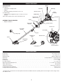 6
6
-
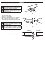 7
7
-
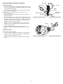 8
8
-
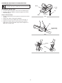 9
9
-
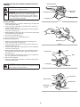 10
10
-
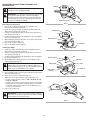 11
11
-
 12
12
-
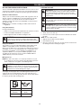 13
13
-
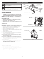 14
14
-
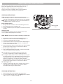 15
15
-
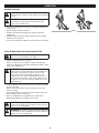 16
16
-
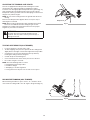 17
17
-
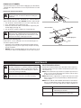 18
18
-
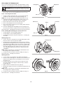 19
19
-
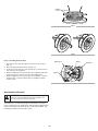 20
20
-
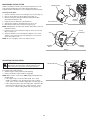 21
21
-
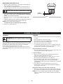 22
22
-
 23
23
-
 24
24
-
 25
25
-
 26
26
-
 27
27
-
 28
28
-
 29
29
-
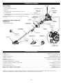 30
30
-
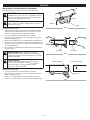 31
31
-
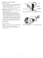 32
32
-
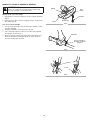 33
33
-
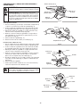 34
34
-
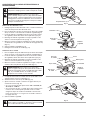 35
35
-
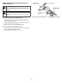 36
36
-
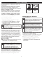 37
37
-
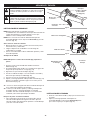 38
38
-
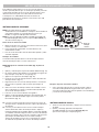 39
39
-
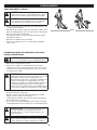 40
40
-
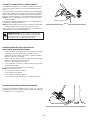 41
41
-
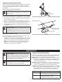 42
42
-
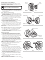 43
43
-
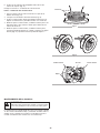 44
44
-
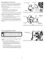 45
45
-
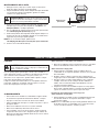 46
46
-
 47
47
-
 48
48


Troy-Bilt TB27 BC Manual de usuario
- Categoría
- Podadoras de césped
- Tipo
- Manual de usuario
- Este manual también es adecuado para
En otros idiomas
- English: Troy-Bilt TB27 BC User manual
Documentos relacionados
-
Troy-Bilt 41AD304H766 Manual de usuario
-
-
-
-
Troy-Bilt TB32 EC Manual de usuario
-
-
-
Yard-Man P/N 769-01473 Manual de usuario
-
MTD TB425CS El manual del propietario
Otros documentos
-
Craftsman CMXGTAMD30SA El manual del propietario
-
-
-
-
-
-
Cub Cadet ST228 Manual de usuario
-
-