Yamaha VP1 El manual del propietario
- Categoría
- Sintetizador
- Tipo
- El manual del propietario


Bescheinigung des Importeurs
Hiermit wird bescheinigt, daß der/die/das
Gerät: Synthesizer Typ: VP1
- - - - - - - - - - - - - - - - - - - - - - - - - - - - - - - - - - - - - - - - - - - - - - - - - - - - - - -
(Gerät, typ, Bezeichnung)
in Übereinstimmung mit den Bestimmungen der
VERFÜGUNG 1046/84
- - - - - - - - - - - - - - - - - - - - - - - - - - - - - - - - - - - - - - - - - - - - - - -
(Amtsblattverfügung)
funkentstört ist.
Der Deutschen Bundespost wurde das
Inverkehrbringen dieses Gerätes angezeigt und die
Berechtigung zur Überprüfung der Serie auf
Einhaltung der Bestimmungen eingeräumt.
Yamaha Europa GmbH
- - - - - - - - - - - - - - - - - - - - - - - - - - - - - - - - - - - - - - - - - - - - -
Name des lmporteurs.
*
Dies bezieht sich nur auf die von der YAMAHA EUROPA
GmbH vertriebenen Produkte.
IMPORTANT NOTICE FOR THE UNITED KINGDOM
Connecting the Plug and Cord
IMPORTANT: The wires in this mains lead are coloured in
accordance with the following code:
GREEN-AND-YELLOW : EARTH
BLUE : NEUTRAL
BROWN : LIVE
As the colours of the wires in the mains lead of this apparatus
may not correspond with the coloured markings identifying the
terminals in your plug, proceed as follows:
The wire which is coloured GREEN and YELLOW must be con-
nected to the terminal in the plug which is marked by the letter E
or by the safety earth symbol or coloured GREEN and YEL-
LOW.
The wire which is coloured BLUE must be connected to the ter-
minal which is marked with the letter N or coloured BLACK.
The wire which is coloured BROWN must be connected to the
terminal which is marked with the letter L or coloured RED.
Dette apparat overholder det gaeldende EF-direktiv
vedrørende radiostøj.
Cet appareil est conforme aux prescriptions de la
directive communautaire 87/308/CEE.
Diese Geräte entsprechen der EG-Richtlinie 82/499/
EWG und/oder 87/308/EWG.
This product complies with the radio frequency in-
terference requirements of the Council Directive 82/
499/EEC and/or 87/308/EEC.
Questo apparecchio è conforme al D.M.13 aprile
1989 (Direttiva CEE/87/308) sulla soppressione dei
radiodisturbi.
Este producto está de acuerdo con los requisitos
sobre interferencias de radio frequencia fijados por
el Consejo Directivo 87/308/CEE.
YAMAHA CORPORATION
ADVARSEL!
Lithiumbatteri—Eksplosionsfare ved fejlagtig håndtering.
Udskiftning må kun ske med batteri af samme fabrikat og type.
Levér det brugte batteri tilbage til leverandoren.
VARNING
Explosionsfara vid felaktigt batteribyte. Använd samma
batterityp eller en ekvivalent typ som rekommenderas av
apparattillverkaren. Kassera använt batteri enligt fabrikantens
instruktion.
VAROITUS
Paristo voi räjähtää, jos se on virheellisesti asennettu. Vaihda
paristo ainoastaan laitevalmistajan suosittelemaan tyyppiin.
Hävitä käytetty paristo valmistajan ohjeiden mukaisesti.

i
VP1 OWNER’S MANUAL
Owner’ s Manual
Thank you for your purchase of the Yamaha VP1 Virtual Acoustic
Synthesizer. The VP1’s revolutionary VA sound system offers a range
of sounds and performance features not available from ordinary
synthesizers.
Please read through this manual to familiarize yourself with the VP1’s
operation and its many superlative functions. Retain the manual in a
safe place for future reference.

ii
VP1 OWNER’S MANUAL
Features
Revolutionary Virtual-Acoustic Sound System
The VP1’s VA (virtual acoustic) sound production is entirely different from
techniques used on conventional synthesizers. The system generates a computerized
model of the target instrument’s acoustic characteristics, creating a virtual instrument
that sounds and feels like the real thing.
Conventional synthesizers create sound by mixing monotone oscillations or by processing
a memorized set of waveform samples. Results are often uninteresting, or too far from what
you are aiming at. You can try to improve the sound by manipulating a host of seemingly
arbitrary settings, but the process frequently becomes tedious and discouraging.
Yamaha’s VA system changes this picture entirely. Operation is intuitively
reasonable, and the resulting sound is far more realistic.
The VP1 utilizes an F/VA (free-oscillating VA) sound system — one of the two
variants of the VA approach. The system creates a computerized model consisting of
two modules: a “driver” component and a “string” component. The driver component
simulates the action of the striking system (analogous to the action of a pick or finger
against a guitar string), while the string component simulates the action of the
vibrating system (analogous to the combination of the guitar’s string, fret, and bridge).
The VP1 fine-tunes the properties of each of these modules to produce a virtual
instrument with an extremely realistic sound.
You can use the VP1 to reproduce the sound of existing acoustic instruments, or to
design fanciful virtual instruments that could never exist in the real world. Regardless
of the type of instrument you choose, the resulting sound will have an authentic, real-
world quality not available from conventional synthesizers.
Powerful Controllers
The VP1’s powerful controllers allow you to achieve an expressive range previously
available only to skilled performers of acoustic instruments.
Consider a guitar player. The guitarist’s sound is determined not just by the finger on
the fret and the pick against the string. Many different actions are involved — the force
and direction of the pick, the left hand’s muting, vibrato, glissando, and trill effects,
the right hand’s muting and harmonic effects, the motion of the right arm, and so on.
It would be impossible to simulate all of these different actions using only the
keyboard. This is why the VP1 supports a full assortment of controllers — a pitch
wheel, two modulation wheels, a two-directional modulation ball, a breath controller,
two foot controllers, two foot switches, and two continuous sliders. By mastering the
use of these controllers, you can achieve a high level of expressiveness on any voice
you happen to be playing.

iii
VP1 OWNER’S MANUAL
Generally speaking, each controller governs a single parameter. But each time you
change the voice, the VP1 changes the parameter assignments accordingly — ensuring
that you always have significant control over the most important features of the voice
you are playing. You are also free to rearrange the parameters among the different
controllers so as to achieve the configuration best suited to your own playing style.
The VP1’s controller features allow you break through the barriers of electronic
instrumentation to achieve a level of control previously limited to acoustic instruments.
Kaleidoscopic “Scene” Control
The VP1 can store all controller settings into a single “scene”. You can register up to
three of these scenes, and recall any one of them at the press of a button. Or you can
use the Scene Controller to fade seamlessly from one scene into another, stopping at
any intermediate value along the way. This unique “scene” concept allows you to
produce unprecedented multidimensional sound changes.
High-Quality Effects
The VP1 offers five times as many as effects the SPX1000 — reverb, flanger, delay,
chorus, and many more. You can set these effects separately for each voice.
Professional Features
■ Professional Parallel Output
The VP1 processes effects internally to produce high-quality stereo output. You are
also free to select monaural output.
The VP1 also produces separate stereo outputs for each of the four elements
comprising the voice. You can connect all of these outputs to a mixer and add external
effects.
■ First VA System with 16-Note Polyphony
The VP1 is the world’s only VA system capable of producing 16-note polyphony. The
four-element voice structure affords ample capability for setting up complex
multilayered and split voices.
■ Superlative Design
The VP1’s FS76 keyboard already enjoys a high reputation among professional
musicians. All VP1 controllers are equipped with multicolor LEDs, allowing you to
ascertain controller conditions at a glance. And the instrument’s top and rear panels
are finished with high-quality real wood trim. Each panel has its own unique grain
pattern, so that no two synthesizers look exactly alike.
■ Complexity
The VP1 simulates an acoustic instrument not only in sound but also in sophistication
and complexity. Like an acoustic instrument, the VP1 requires — and amply rewards
— practice. As you master the instrument’s controllers and functions, you will
gradually attain your own unique, personalized performance style.

iv
VP1 OWNER’S MANUAL
Using The Manual
The manual you are holding is divided into two main sections — BASICS and REFERENCE.
BASICS
This section introduces you to basic information that will help you become familiar with your synthesizer. The
section explains various precautions, tells you how to connect up the synthesizer, takes you through a trial run, and
describes the basic principles of operation and sound production.
Users who are unfamiliar with the VP1 should read through the entire BASICS section carefully.
■ Chapter 1 Setting It Up
This chapter introduces you to the different components and explains how to connect
everything up.
■ Chapter 2 Trying it Out
Chapter 2 takes you through a trial run and introduces some of the VP1’s operational
basics. It also explains how to play the synthesizer’s built-in demos.
■ Chapter 3 Learning the Basics
Chapter 3 describes the principles of operation, and explains the functioning of
controllers and other features.
REFERENCE
The REFERENCE section offers detailed explanations of the VP1’s different functions. It describes in detail the various
methods for implementing performance, voice, and controller settings, and for writing data to or from the floppy disk.
You do not need to read through the REFERENCE section in its entirety. Use it as a ready reference, turning to the
relevant pages whenever you need to learn more about a particular function.
■ Chapter 1 PLAY Mode
This chapter provides comprehensive explanations of the functions for selecting,
playing, and editing voices.
■ Chapter 2 SYSTEM Mode
Chapter 2 explains system-wide settings related to sound production, keyboard
operation, MIDI, and controllers.
■ Chapter 3 DISK Mode
This chapter describes the VP1’s various disk functions. It explains how to save data
to disk, load data from disk, format new disks, and rename existing disk files.
■ Appendix
The Appendix describes the system’s error messages and offers some advice on
troubleshooting.
Please refer also to the separately bound “Performance Notes” for a full listing of the VP1’s original voices and
functions.

v
VP1 OWNER’S MANUAL
Notations
The following notational conventions are used throughout the manual to enhance clarity and readability.
PLAY
Denotes the PLAY button. All buttons are indicated by a rounded rectangular border
enclosing the button (function) name. Note that the function name also appears on the
synthesizer panel directly above or below the corresponding button. Some buttons
have two functions, with the name of the secondary function written in purple lettering
on the panel. When referring to the purple-lettered function, we use the following type
of notation: “
F1
:E1”, where “
F1
” denotes the button’s usual function and
“E1” denotes the function indicated in purple.
When referring to a function button (
F1
~
F8
), we write the symbol for the
button followed by the name of the operation that the button selects. For example:
F1
:Info.
Important
An important note or precaution intended to help you avoid loss of data or other major
inconvenience. Always read these notices carefully.
FYI (For your information)
Reference information indirectly related to the content of the main text. May contain
practical advice or general supplementary information.
Procedure
Step-by-step instructions for carrying out a particular function or operation.
Description
General description of one of the VP1’s functions.
(➝ BASICS: - ) (➝ REFERENCE: - )
Directs you to another page for related information.
Within the REFERENCE section, all function descriptions begin with a fixed-format heading
summarizing important information about the function. An example is shown below.
CONTROLLER ASSIGN TABLE: Control Range
PLAY
→
F4
(CTbl) →
F1
([Rng])
Determines the degree by which a parameter value changes in response to controller movement.
Max 0 ~ 127
Center 0 ~ 127
Min 0 ~ 127
Settable items (Listed
in the order that they
appear on the screen).
Allowable values
Display
Name of function
Procedure for entering the function
Brief description

vi
VP1 OWNER’S MANUAL
Contents
All page numbers begin with a letter indicating the section: “B” for BASICS, or “R” for REFERENCE.
BASICS
Chapter 1 Setting It Up
Controls and Connectors • • • • • • • • • • • • • • • • • • • • • • • • • • • • • • • • • • • • • • • • • • • • • • • • • • • • • • • • • • • • • • • • • • • • • • • • • • • • • • • • • • • • • • • • • • • • B: 1 - 2
Top Panel • • • • • • • • • • • • • • • • • • • • • • • • • • • • • • • • • • • • • • • • • • • • • • • • • • • • • • • • • • • • • • • • • • • • • • • • • • • B: 1 - 2
Rear Panel • • • • • • • • • • • • • • • • • • • • • • • • • • • • • • • • • • • • • • • • • • • • • • • • • • • • • • • • • • • • • • • • • • • • • • • • • • • B: 1 - 6
Front Side • • • • • • • • • • • • • • • • • • • • • • • • • • • • • • • • • • • • • • • • • • • • • • • • • • • • • • • • • • • • • • • • • • • • • • • • • • • B: 1 - 8
Connecting the System • • • • • • • • • • • • • • • • • • • • • • • • • • • • • • • • • • • • • • • • • • • • • • • • • • • • • • • • • • • • • • • • • • • • • • • • • • • • • • • • • • • • • • • • • • • • • • B: 1 - 9
Connecting the Power Cord • • • • • • • • • • • • • • • • • • • • • • • • • • • • • • • • • • • • • • • • • • • • • • • • • • • • • • • • • • B: 1 - 9
Connecting the Controllers • • • • • • • • • • • • • • • • • • • • • • • • • • • • • • • • • • • • • • • • • • • • • • • • • • • • • • • • • B: 1 - 10
Connecting Amplifiers or Mixer • • • • • • • • • • • • • • • • • • • • • • • • • • • • • • • • • • • • • • • • • • • • • • • • • • • • B: 1 - 12
MIDI Connection • • • • • • • • • • • • • • • • • • • • • • • • • • • • • • • • • • • • • • • • • • • • • • • • • • • • • • • • • • • • • • • • • • B: 1 - 14
The Floppy Disk • • • • • • • • • • • • • • • • • • • • • • • • • • • • • • • • • • • • • • • • • • • • • • • • • • • • • • • • • • • • • • • • • • • • • • • • • • • • • • • • • • • • • • • • • • • • • • • • • • • B: 1 - 16
MIDI • • • • • • • • • • • • • • • • • • • • • • • • • • • • • • • • • • • • • • • • • • • • • • • • • • • • • • • • • • • • • • • • • • • • • • • • • • • • • • • • • • • • • • • • • • • • • • • • • • • • • • • • • • • • • • B: 1 - 17
Chapter 2 Trying It Out
First Try • • • • • • • • • • • • • • • • • • • • • • • • • • • • • • • • • • • • • • • • • • • • • • • • • • • • • • • • • • • • • • • • • • • • • • • • • • • • • • • • • • • • • • • • • • • • • • • • • • • • • • • • • • • • B: 2 - 2
Checking the Sound Output • • • • • • • • • • • • • • • • • • • • • • • • • • • • • • • • • • • • • • • • • • • • • • • • • • • • • • • • • • B: 2 - 2
Trying Some Voices • • • • • • • • • • • • • • • • • • • • • • • • • • • • • • • • • • • • • • • • • • • • • • • • • • • • • • • • • • • • • • • • • B: 2 - 3
Using the Controllers • • • • • • • • • • • • • • • • • • • • • • • • • • • • • • • • • • • • • • • • • • • • • • • • • • • • • • • • • • • • • • • • B: 2 - 4
Using Quick Edit • • • • • • • • • • • • • • • • • • • • • • • • • • • • • • • • • • • • • • • • • • • • • • • • • • • • • • • • • • • • • • • • • • • • B: 2 - 6
Playing the Demos • • • • • • • • • • • • • • • • • • • • • • • • • • • • • • • • • • • • • • • • • • • • • • • • • • • • • • • • • • • • • • • • • • • • • • • • • • • • • • • • • • • • • • • • • • • • • • • • • • B: 2 - 8
Chapter 3 Learning the Basics
Sound Production • • • • • • • • • • • • • • • • • • • • • • • • • • • • • • • • • • • • • • • • • • • • • • • • • • • • • • • • • • • • • • • • • • • • • • • • • • • • • • • • • • • • • • • • • • • • • • • • • • • B: 3 - 2
F/VA Sound Synthesis • • • • • • • • • • • • • • • • • • • • • • • • • • • • • • • • • • • • • • • • • • • • • • • • • • • • • • • • • • • • • • B: 3 - 2
Physical Characteristics of Struck-String Instruments • • • • • • • • • • • • • • • • • • • • • • • • • • • • • • • • B: 3 - 2
Driver • • • • • • • • • • • • • • • • • • • • • • • • • • • • • • • • • • • • • • • • • • • • • • • • • • • • • • • • • • • • • • • • • • • • • • • • • • • • • • • B: 3 - 3
String • • • • • • • • • • • • • • • • • • • • • • • • • • • • • • • • • • • • • • • • • • • • • • • • • • • • • • • • • • • • • • • • • • • • • • • • • • • • • • • B: 3 - 3
Editing Limitations • • • • • • • • • • • • • • • • • • • • • • • • • • • • • • • • • • • • • • • • • • • • • • • • • • • • • • • • • • • • • • • • • • B: 3 - 3
Voice Formation • • • • • • • • • • • • • • • • • • • • • • • • • • • • • • • • • • • • • • • • • • • • • • • • • • • • • • • • • • • • • • • • • • • • • • • • • • • • • • • • • • • • • • • • • • • • • • • • • • • • B: 3 - 4
Elements • • • • • • • • • • • • • • • • • • • • • • • • • • • • • • • • • • • • • • • • • • • • • • • • • • • • • • • • • • • • • • • • • • • • • • • • • • • • B: 3 - 4
Mixer • • • • • • • • • • • • • • • • • • • • • • • • • • • • • • • • • • • • • • • • • • • • • • • • • • • • • • • • • • • • • • • • • • • • • • • • • • • • • • • B: 3 - 5
Voices • • • • • • • • • • • • • • • • • • • • • • • • • • • • • • • • • • • • • • • • • • • • • • • • • • • • • • • • • • • • • • • • • • • • • • • • • • • • • • B: 3 - 5

vii
VP1 OWNER’S MANUAL
Contents
Memory Configuration • • • • • • • • • • • • • • • • • • • • • • • • • • • • • • • • • • • • • • • • • • • • • • • • • • • • • • • • • • • • • • • • • • • • • • • • • • • • • • • • • • • • • • • • • • • • • • B: 3 - 6
System Data • • • • • • • • • • • • • • • • • • • • • • • • • • • • • • • • • • • • • • • • • • • • • • • • • • • • • • • • • • • • • • • • • • • • • • • • • B: 3 - 6
Voice Data • • • • • • • • • • • • • • • • • • • • • • • • • • • • • • • • • • • • • • • • • • • • • • • • • • • • • • • • • • • • • • • • • • • • • • • • • • B: 3 - 6
Floppy Disks • • • • • • • • • • • • • • • • • • • • • • • • • • • • • • • • • • • • • • • • • • • • • • • • • • • • • • • • • • • • • • • • • • • • • • • • B: 3 - 7
Controllers • • • • • • • • • • • • • • • • • • • • • • • • • • • • • • • • • • • • • • • • • • • • • • • • • • • • • • • • • • • • • • • • • • • • • • • • • • • • • • • • • • • • • • • • • • • • • • • • • • • • • • • • • • B: 3 - 8
Principle of Operation • • • • • • • • • • • • • • • • • • • • • • • • • • • • • • • • • • • • • • • • • • • • • • • • • • • • • • • • • • • • • • • B: 3 - 8
Innovative Controller Types • • • • • • • • • • • • • • • • • • • • • • • • • • • • • • • • • • • • • • • • • • • • • • • • • • • • • • • • • B: 3 - 9
Scenes • • • • • • • • • • • • • • • • • • • • • • • • • • • • • • • • • • • • • • • • • • • • • • • • • • • • • • • • • • • • • • • • • • • • • • • • • • • • • • • • • • • • • • • • • • • • • • • • • • • • • • • • • • • • • B: 3 - 11
What is a Scene? • • • • • • • • • • • • • • • • • • • • • • • • • • • • • • • • • • • • • • • • • • • • • • • • • • • • • • • • • • • • • • • • • • • B: 3 - 11
Scene Controller • • • • • • • • • • • • • • • • • • • • • • • • • • • • • • • • • • • • • • • • • • • • • • • • • • • • • • • • • • • • • • • • • • • B: 3 - 12
Scene LEDs • • • • • • • • • • • • • • • • • • • • • • • • • • • • • • • • • • • • • • • • • • • • • • • • • • • • • • • • • • • • • • • • • • • • • • • B: 3 - 13
Controller Hook Function • • • • • • • • • • • • • • • • • • • • • • • • • • • • • • • • • • • • • • • • • • • • • • • • • • • • • • • • • • B: 3 - 14
Controller LEDs • • • • • • • • • • • • • • • • • • • • • • • • • • • • • • • • • • • • • • • • • • • • • • • • • • • • • • • • • • • • • • • • • • • B: 3 - 15
Controller Initialization Function • • • • • • • • • • • • • • • • • • • • • • • • • • • • • • • • • • • • • • • • • • • • • • • • • • • B: 3 - 15
Quick Edit • • • • • • • • • • • • • • • • • • • • • • • • • • • • • • • • • • • • • • • • • • • • • • • • • • • • • • • • • • • • • • • • • • • • • • • • • • • • • • • • • • • • • • • • • • • • • • • • • • • • • • • • • B: 3 - 16
General Description • • • • • • • • • • • • • • • • • • • • • • • • • • • • • • • • • • • • • • • • • • • • • • • • • • • • • • • • • • • • • • • • B: 3 - 16
Using Quick Edit • • • • • • • • • • • • • • • • • • • • • • • • • • • • • • • • • • • • • • • • • • • • • • • • • • • • • • • • • • • • • • • • • • • B: 3 - 17
Storing Results • • • • • • • • • • • • • • • • • • • • • • • • • • • • • • • • • • • • • • • • • • • • • • • • • • • • • • • • • • • • • • • • • • • • • B: 3 - 17
Quick-Edit Parameters • • • • • • • • • • • • • • • • • • • • • • • • • • • • • • • • • • • • • • • • • • • • • • • • • • • • • • • • • • • • • B: 3 - 18
MIDI Quick Edit Control • • • • • • • • • • • • • • • • • • • • • • • • • • • • • • • • • • • • • • • • • • • • • • • • • • • • • • • • • • • B: 3 - 20
Voice Categories • • • • • • • • • • • • • • • • • • • • • • • • • • • • • • • • • • • • • • • • • • • • • • • • • • • • • • • • • • • • • • • • • • • • • • • • • • • • • • • • • • • • • • • • • • • • • • • • • • B: 3 - 21
Category Listing • • • • • • • • • • • • • • • • • • • • • • • • • • • • • • • • • • • • • • • • • • • • • • • • • • • • • • • • • • • • • • • • • • • B: 3 - 21
Modes • • • • • • • • • • • • • • • • • • • • • • • • • • • • • • • • • • • • • • • • • • • • • • • • • • • • • • • • • • • • • • • • • • • • • • • • • • • • • • • • • • • • • • • • • • • • • • • • • • • • • • • • • • • • • B: 3 - 22
PLAY Mode • • • • • • • • • • • • • • • • • • • • • • • • • • • • • • • • • • • • • • • • • • • • • • • • • • • • • • • • • • • • • • • • • • • • • • • B: 3 - 22
SYSTEM Mode • • • • • • • • • • • • • • • • • • • • • • • • • • • • • • • • • • • • • • • • • • • • • • • • • • • • • • • • • • • • • • • • • • • • B: 3 - 22
DISK Mode • • • • • • • • • • • • • • • • • • • • • • • • • • • • • • • • • • • • • • • • • • • • • • • • • • • • • • • • • • • • • • • • • • • • • • • • B: 3 - 22
Basic Operations • • • • • • • • • • • • • • • • • • • • • • • • • • • • • • • • • • • • • • • • • • • • • • • • • • • • • • • • • • • • • • • • • • • • • • • • • • • • • • • • • • • • • • • • • • • • • • • • • • • B: 3 - 23
Switching the Mode • • • • • • • • • • • • • • • • • • • • • • • • • • • • • • • • • • • • • • • • • • • • • • • • • • • • • • • • • • • • • • • • B: 3 - 23
Selecting a Voice • • • • • • • • • • • • • • • • • • • • • • • • • • • • • • • • • • • • • • • • • • • • • • • • • • • • • • • • • • • • • • • • • • • B: 3 - 23
Selecting a Function • • • • • • • • • • • • • • • • • • • • • • • • • • • • • • • • • • • • • • • • • • • • • • • • • • • • • • • • • • • • • • • • B: 3 - 24
Returning to Previous Screen • • • • • • • • • • • • • • • • • • • • • • • • • • • • • • • • • • • • • • • • • • • • • • • • • • • • • • • B: 3 - 24
Moving the Cursor • • • • • • • • • • • • • • • • • • • • • • • • • • • • • • • • • • • • • • • • • • • • • • • • • • • • • • • • • • • • • • • • • B: 3 - 24
Changing Numerical Settings • • • • • • • • • • • • • • • • • • • • • • • • • • • • • • • • • • • • • • • • • • • • • • • • • • • • • • • B: 3 - 25
Changing Multiple-Choice Settings • • • • • • • • • • • • • • • • • • • • • • • • • • • • • • • • • • • • • • • • • • • • • • • • • B: 3 - 25
Entering Characters • • • • • • • • • • • • • • • • • • • • • • • • • • • • • • • • • • • • • • • • • • • • • • • • • • • • • • • • • • • • • • • • B: 3 - 26
Voice Editing • • • • • • • • • • • • • • • • • • • • • • • • • • • • • • • • • • • • • • • • • • • • • • • • • • • • • • • • • • • • • • • • • • • • • • • • • • • • • • • • • • • • • • • • • • • • • • • • • • • • • • B: 3 - 27
General Editing Procedure • • • • • • • • • • • • • • • • • • • • • • • • • • • • • • • • • • • • • • • • • • • • • • • • • • • • • • • • • • B: 3 - 27
Storing • • • • • • • • • • • • • • • • • • • • • • • • • • • • • • • • • • • • • • • • • • • • • • • • • • • • • • • • • • • • • • • • • • • • • • • • • • • • • B: 3 - 28
Comparing • • • • • • • • • • • • • • • • • • • • • • • • • • • • • • • • • • • • • • • • • • • • • • • • • • • • • • • • • • • • • • • • • • • • • • • • • B: 3 - 30
Copying • • • • • • • • • • • • • • • • • • • • • • • • • • • • • • • • • • • • • • • • • • • • • • • • • • • • • • • • • • • • • • • • • • • • • • • • • • • • B: 3 - 30
ELEMENT SELECT and ELEMENT ON/OFF • • • • • • • • • • • • • • • • • • • • • • • • • • • • • • • • • • • • • B: 3 - 31

viii
VP1 OWNER’S MANUAL
Contents
REFERENCE
Chapter 1 PLAY Mode
Outline • • • • • • • • • • • • • • • • • • • • • • • • • • • • • • • • • • • • • • • • • • • • • • • • • • • • • • • • • • • • • • • • • • • • • • • • • • • • • • • • • • • • • • • • • • • • • • • • • • • • • • • • • • • • • R: 1 - 2
Performance and Status • • • • • • • • • • • • • • • • • • • • • • • • • • • • • • • • • • • • • • • • • • • • • • • • • • • • • • • • • • • • • • • • • • • • • • • • • • • • • • • • • • • • • • • • • • • • • R: 1 - 3
Functions • • • • • • • • • • • • • • • • • • • • • • • • • • • • • • • • • • • • • • • • • • • • • • • • • • • • • • • • • • • • • • • • • • • • • • • • • • • • R: 1 - 3
PLAY • • • • • • • • • • • • • • • • • • • • • • • • • • • • • • • • • • • • • • • • • • • • • • • • • • • • • • • • • • • • • • • • • • • • • • • • • • • • • • • R: 1 - 4
INFORMATION DISPLAY • • • • • • • • • • • • • • • • • • • • • • • • • • • • • • • • • • • • • • • • • • • • • • • • • • • • • • • • • R: 1 - 5
CONTROLLER VALUE VIEW • • • • • • • • • • • • • • • • • • • • • • • • • • • • • • • • • • • • • • • • • • • • • • • • • • • • • R: 1 - 6
KEYBOARD TRANSMIT CHANNEL • • • • • • • • • • • • • • • • • • • • • • • • • • • • • • • • • • • • • • • • • • • • • • R: 1 - 7
VOICE DIRECTORY • • • • • • • • • • • • • • • • • • • • • • • • • • • • • • • • • • • • • • • • • • • • • • • • • • • • • • • • • • • • • • • R: 1 - 8
Editing Functions • • • • • • • • • • • • • • • • • • • • • • • • • • • • • • • • • • • • • • • • • • • • • • • • • • • • • • • • • • • • • • • • • • • • • • • • • • • • • • • • • • • • • • • • • • • • • • • • • • • R: 1 - 9
CONTROLLER ASSIGN TABLE • • • • • • • • • • • • • • • • • • • • • • • • • • • • • • • • • • • • • • • • • • • • • • • • • R: 1 - 10
CONTROLLER ASSIGN TABLE: Control Range • • • • • • • • • • • • • • • • • • • • • • • • • • • • • • • • • R: 1 - 12
SCENE • • • • • • • • • • • • • • • • • • • • • • • • • • • • • • • • • • • • • • • • • • • • • • • • • • • • • • • • • • • • • • • • • • • • • • • • • • • • R: 1 - 14
VOICE SETUP • • • • • • • • • • • • • • • • • • • • • • • • • • • • • • • • • • • • • • • • • • • • • • • • • • • • • • • • • • • • • • • • • • • • R: 1 - 16
VOICE SETUP: Element Switch • • • • • • • • • • • • • • • • • • • • • • • • • • • • • • • • • • • • • • • • • • • • • • • • • • • R: 1 - 17
VOICE SETUP: Max Notes • • • • • • • • • • • • • • • • • • • • • • • • • • • • • • • • • • • • • • • • • • • • • • • • • • • • • • • • R: 1 - 18
VOICE SETUP: Receive Channel • • • • • • • • • • • • • • • • • • • • • • • • • • • • • • • • • • • • • • • • • • • • • • • • • • R: 1 - 19
VOICE SETUP: Key Assign Mode • • • • • • • • • • • • • • • • • • • • • • • • • • • • • • • • • • • • • • • • • • • • • • • • • R: 1 - 20
VOICE SETUP: Volume • • • • • • • • • • • • • • • • • • • • • • • • • • • • • • • • • • • • • • • • • • • • • • • • • • • • • • • • • • • R: 1 - 22
VOICE SETUP: Detune • • • • • • • • • • • • • • • • • • • • • • • • • • • • • • • • • • • • • • • • • • • • • • • • • • • • • • • • • • • • R: 1 - 23
VOICE SETUP: Note Shift • • • • • • • • • • • • • • • • • • • • • • • • • • • • • • • • • • • • • • • • • • • • • • • • • • • • • • • • • R: 1 - 24
VOICE SETUP: Pan Range • • • • • • • • • • • • • • • • • • • • • • • • • • • • • • • • • • • • • • • • • • • • • • • • • • • • • • • • R: 1 - 25
VOICE SETUP: Note Limit • • • • • • • • • • • • • • • • • • • • • • • • • • • • • • • • • • • • • • • • • • • • • • • • • • • • • • • • R: 1 - 27
VOICE SETUP: Microtuning • • • • • • • • • • • • • • • • • • • • • • • • • • • • • • • • • • • • • • • • • • • • • • • • • • • • • • R: 1 - 28
VOICE SETUP: Portamento Mode • • • • • • • • • • • • • • • • • • • • • • • • • • • • • • • • • • • • • • • • • • • • • • • • • R: 1 - 30
VOICE SETUP: Portamento Resolution • • • • • • • • • • • • • • • • • • • • • • • • • • • • • • • • • • • • • • • • • • • • R: 1 - 31
VOICE SETUP: PB Range • • • • • • • • • • • • • • • • • • • • • • • • • • • • • • • • • • • • • • • • • • • • • • • • • • • • • • • • • R: 1 - 32
VOICE SETUP: PB Curve • • • • • • • • • • • • • • • • • • • • • • • • • • • • • • • • • • • • • • • • • • • • • • • • • • • • • • • • • R: 1 - 33
VOICE SETUP: Zoned Aftertouch Mode • • • • • • • • • • • • • • • • • • • • • • • • • • • • • • • • • • • • • • • • • • • R: 1 - 35
VOICE SETUP: Zoned Aftertouch Split • • • • • • • • • • • • • • • • • • • • • • • • • • • • • • • • • • • • • • • • • • • • R: 1 - 36
VOICE SETUP: Sustain • • • • • • • • • • • • • • • • • • • • • • • • • • • • • • • • • • • • • • • • • • • • • • • • • • • • • • • • • • • • R: 1 - 37
VOICE SETUP: Element Copy • • • • • • • • • • • • • • • • • • • • • • • • • • • • • • • • • • • • • • • • • • • • • • • • • • • • • R: 1 - 38
OUTPUT: MIXER • • • • • • • • • • • • • • • • • • • • • • • • • • • • • • • • • • • • • • • • • • • • • • • • • • • • • • • • • • • • • • • • • R: 1 - 41
OUTPUT: EFFECTS • • • • • • • • • • • • • • • • • • • • • • • • • • • • • • • • • • • • • • • • • • • • • • • • • • • • • • • • • • • • • • • R: 1 - 43
Effect Types • • • • • • • • • • • • • • • • • • • • • • • • • • • • • • • • • • • • • • • • • • • • • • • • • • • • • • • • • • • • • • • • • • • • • • • R: 1 - 44
Effects Parameters • • • • • • • • • • • • • • • • • • • • • • • • • • • • • • • • • • • • • • • • • • • • • • • • • • • • • • • • • • • • • • • • • R: 1 - 45
OUTPUT: Effect Copy • • • • • • • • • • • • • • • • • • • • • • • • • • • • • • • • • • • • • • • • • • • • • • • • • • • • • • • • • • • • • R: 1 - 50
OUTPUT: Equalizer • • • • • • • • • • • • • • • • • • • • • • • • • • • • • • • • • • • • • • • • • • • • • • • • • • • • • • • • • • • • • • • R: 1 - 51
OUTPUT: Equalizer Copy • • • • • • • • • • • • • • • • • • • • • • • • • • • • • • • • • • • • • • • • • • • • • • • • • • • • • • • • • R: 1 - 53
STORE • • • • • • • • • • • • • • • • • • • • • • • • • • • • • • • • • • • • • • • • • • • • • • • • • • • • • • • • • • • • • • • • • • • • • • • • • • • • R: 1 - 54
COMPARE • • • • • • • • • • • • • • • • • • • • • • • • • • • • • • • • • • • • • • • • • • • • • • • • • • • • • • • • • • • • • • • • • • • • • • • • R: 1 - 56

ix
VP1 OWNER’S MANUAL
Contents
Chapter 2 SYSTEM Mode
Outline • • • • • • • • • • • • • • • • • • • • • • • • • • • • • • • • • • • • • • • • • • • • • • • • • • • • • • • • • • • • • • • • • • • • • • • • • • • • • • • • • • • • • • • • • • • • • • • • • • • • • • • • • • • • • R: 2 - 2
SYSTEM Functions • • • • • • • • • • • • • • • • • • • • • • • • • • • • • • • • • • • • • • • • • • • • • • • • • • • • • • • • • • • • • • • • • • • • • • • • • • • • • • • • • • • • • • • • • • • • • • • • • R: 2 - 3
TONE GENERATOR SETTINGS • • • • • • • • • • • • • • • • • • • • • • • • • • • • • • • • • • • • • • • • • • • • • • • • • • • R: 2 - 4
KEYBOARD SETTINGS • • • • • • • • • • • • • • • • • • • • • • • • • • • • • • • • • • • • • • • • • • • • • • • • • • • • • • • • • • • R: 2 - 6
MIDI SETTINGS • • • • • • • • • • • • • • • • • • • • • • • • • • • • • • • • • • • • • • • • • • • • • • • • • • • • • • • • • • • • • • • • • • • R: 2 - 8
ASSIGNABLE CONTROLLERS • • • • • • • • • • • • • • • • • • • • • • • • • • • • • • • • • • • • • • • • • • • • • • • • • • R: 2 - 10
GREETING MESSAGE • • • • • • • • • • • • • • • • • • • • • • • • • • • • • • • • • • • • • • • • • • • • • • • • • • • • • • • • • • • R: 2 - 12
MISCELLANEOUS SETTINGS • • • • • • • • • • • • • • • • • • • • • • • • • • • • • • • • • • • • • • • • • • • • • • • • • • • R: 2 - 13
Chapter 3 DISK Mode
Outline • • • • • • • • • • • • • • • • • • • • • • • • • • • • • • • • • • • • • • • • • • • • • • • • • • • • • • • • • • • • • • • • • • • • • • • • • • • • • • • • • • • • • • • • • • • • • • • • • • • • • • • • • • • • • R: 3 - 2
DISK Functions • • • • • • • • • • • • • • • • • • • • • • • • • • • • • • • • • • • • • • • • • • • • • • • • • • • • • • • • • • • • • • • • • • • • • • • • • • • • • • • • • • • • • • • • • • • • • • • • • • • • • R: 3 - 3
LOAD ALL DATA • • • • • • • • • • • • • • • • • • • • • • • • • • • • • • • • • • • • • • • • • • • • • • • • • • • • • • • • • • • • • • • • • R: 3 - 4
LOAD 1 BANK • • • • • • • • • • • • • • • • • • • • • • • • • • • • • • • • • • • • • • • • • • • • • • • • • • • • • • • • • • • • • • • • • • • • • R: 3 - 5
LOAD 1 VOICE • • • • • • • • • • • • • • • • • • • • • • • • • • • • • • • • • • • • • • • • • • • • • • • • • • • • • • • • • • • • • • • • • • • • R: 3 - 7
SAVE ALL DATA • • • • • • • • • • • • • • • • • • • • • • • • • • • • • • • • • • • • • • • • • • • • • • • • • • • • • • • • • • • • • • • • • • R: 3 - 9
RENAME • • • • • • • • • • • • • • • • • • • • • • • • • • • • • • • • • • • • • • • • • • • • • • • • • • • • • • • • • • • • • • • • • • • • • • • • • • R: 3 - 11
FORMAT • • • • • • • • • • • • • • • • • • • • • • • • • • • • • • • • • • • • • • • • • • • • • • • • • • • • • • • • • • • • • • • • • • • • • • • • • • R: 3 - 12
Appendix
Function List • • • • • • • • • • • • • • • • • • • • • • • • • • • • • • • • • • • • • • • • • • • • • • • • • • • • • • • • • • • • • • • • • • • • • • • • • • • • • • • • • • • • • • • • • • • • • • • R: Appendix - 2
Troubleshooting • • • • • • • • • • • • • • • • • • • • • • • • • • • • • • • • • • • • • • • • • • • • • • • • • • • • • • • • • • • • • • • • • • • • • • • • • • • • • • • • • • • • • • • • • • • • R: Appendix - 5
Error Messages • • • • • • • • • • • • • • • • • • • • • • • • • • • • • • • • • • • • • • • • • • • • • • • • • • • • • • • • • • • • • • • • • • • • • • • • • • • • • • • • • • • • • • • • • • • • • R: Appendix - 9
Specifications • • • • • • • • • • • • • • • • • • • • • • • • • • • • • • • • • • • • • • • • • • • • • • • • • • • • • • • • • • • • • • • • • • • • • • • • • • • • • • • • • • • • • • • • • • • • • R: Appendix - 11
MIDI Data Format • • • • • • • • • • • • • • • • • • • • • • • • • • • • • • • • • • • • • • • • • • • • • • • • • • • • • • • • • • • • • • • • • • • • • • • • • • • • • • • • • • • • • • • • R: Appendix - 14
MIDI Implementation Chart • • • • • • • • • • • • • • • • • • • • • • • • • • • • • • • • • • • • • • • • • • • • • • • • • • • • • • • • • • • • • • • • • • • • • • • • • • • • • • • R: Appendix - 20
Index
Index • • • • • • • • • • • • • • • • • • • • • • • • • • • • • • • • • • • • • • • • • • • • • • • • • • • • • • • • • • • • • • • • • • • • • • • • • • • • • • • • • • • • • • • • • • • • • • • • • • • • • • • • • • • • • • Index - 2


BASICS
Chapter 1 Setting It Up
1 - 1
Chapter 1
Setting It Up
This chapter introduces the VP1’s various controls and connectors, and
explains how to connect everything up. Users unfamiliar with the VP1
should read this chapter carefully.

BASICS
Chapter 1 Setting It Up
1 - 2
Controls and Connectors
Controls and Connectors
Top Panel
(1) MODULATION BALL
Use this ball to simultaneously control two different parameter values during
performance. Rotation in the X direction controls one parameter, while
rotation in the Y direction controls the other. Control effects differ for each
voice. (➝ BASICS: 3-9)
(2) PITCH wheel
Provides continuous variation of pitch. Depending on voice settings, wheel
operation may also affect other sound qualities.
(3) MODULATION 1 wheel
Controls one voice parameter during performance. The actual effect differs
for each voice.
(4) MODULATION 2 wheel
Controls one voice parameter during performance, where the actual effect
depends on the voice. Unlike the MODULATION 1 wheel, this wheel
includes a center click-stop.
(5) Controller LEDs
Each LED indicates the status of the corresponding controller. GREEN
means that the controller is currently effective, SOLID RED means that the
controller is outside of its effective range, and FLASHING RED means that
the controller is currently effective on some elements only. OFF means that
the controller is currently unassigned. (➝ BASICS: 3-15)
MODULATION BALL
Y
X
PITCH MODULATION 1 MODULATION 2
FOOT
CONTROLLER 1
FOOT
CONTROLLER 2
TOUCH EG
AFTER TOUCH
BREATH
BREATH
CONTROLLERPHONESFDD
CS 1VOLUME

BASICS
Chapter 1 Setting It Up
1 - 3
Controls and Connectors
(6) PLAY button
SYSTEM button
DISK button
Each button selects the corresponding mode. The PLAY button always
switches the display to the initial PLAY screen. (➝ BASICS: 3-22)
(7) STORE button
Stores an edited voice to internal memory, or copies an existing voice to
another location (a different “voice number”). (➝ BASICS: 3-28)
(8) COMPARE button
Use this button to compare the sound of the voice you are editing with the
sound of the same voice before editing began. (➝ BASICS: 3-38)
(9) VOLUME slider
Adjusts the output volume. Note that this slider has no effect on the output
levels at the ELEMENT jacks.
(10) CS1 and CS2 (Continuous sliders)
These sliders provide real-time control of voice parameters during
performance. Actual effects differ for each voice.
(11) SCENE 1, SCENE 2, and SCENE 3 buttons
The VP1 memorizes up to three complete sets of controller settings, or
“scenes”. Pressing one of the SCENE buttons reestablishes the
corresponding set of controller settings.
(12) SCENE CONTROLLER
Use this controller to slide continuously from one scene into another. The
center click-stop position selects Scene 2. (➝ BASICS: 3-12)
PLAY SYSTEM DISK STORE COMPARE
CS 2CS 1VOLUME
SCENE 1 SCENE 2 SCENE 3
SCENE CONTROLLER

BASICS
Chapter 1 Setting It Up
1 - 4
(13) QUICK EDIT selectors ( and )
Use these to select the functions to be controlled by the QUICK EDIT
sliders. (➝ BASICS: 3-16)
(14) QS1, QS2, QS3, and QS4 (Quick-edit sliders)
Use these sliders for quick editing. The LEDs along the right side of each
slider indicate the slider’s position. If the slider is at center position, the two
middle LEDs will be on. (➝ BASICS: 3-17)
(15) C3 key mark
Marks the position of note C3 on the keyboard. The marking is not
meaningful if the keyboard has been transposed.
(16) Display
The LCD displays the name of the currently selected voice, together with
various status information. Characters may be displayed black-on-white or
white-on-black. (➝ REFERENCE: 2-13) The screen’s contrast level may
change slightly over the course of a long session; adjust as necessary using
the CONT knob. (➝ REFERENCE: 2-13)
(17) F1 to F8 (Function buttons)
Use these buttons to select various functions while playing or editing. The
bottom line of the LCD indicates the currently available functions.
(18) CONT knob
Adjusts the LCD’s contrast.
Controls and Connectors
EQ LOW
AT FOLLOW
LFO DEPTH
EG ATTACK
EQ LO-MID
VEL SENS
LFO SPEED
EG DECAY
EQ HI-MID
POR TIME
LFO DELAY
EG SUSTN
EQ HIGH
EF DEPTH
LFO HOLD
EG RELSE
QS4QS3QS2QS1
QUICK EDIT
F1 F2 F3 F4 F5 F6 F7 F8 CONT
C3

BASICS
Chapter 1 Setting It Up
1 - 5
Controls and Connectors
(19) Dial
Use to switch voices or to change a numerical or character value. The
magnitude of change varies in proportion to the speed of dial rotation.
(20) DEC/NO button
INC/YES button
Press to increment or decrement a numerical or character value, or to answer
“YES” or “NO” to a confirmation query.
(21) Cursor buttons
Use these buttons to move the screen’s cursor to a different menu item or
value.
(22) EXIT button
Use this button to exit from the currently displayed screen (submode),
returning the LCD to the next higher-level screen.
(23) ENTER button
Press this button to select or execute a function.
(24) A to D: Voice bank buttons
Use these buttons to select the voice bank (A to D).
(25) 1 to 16: Program buttons
Use these buttons to select a voice (by voice number) from the current voice
bank. During voice editing, buttons 1 to 4 select voice elements, and buttons
9 to 12 toggle voice elements on and off. (➝ BASICS: 3-31)
DEC/NO INC/YES
EXIT ENTER
9
E1
10
E2
11
E3
12
E4
13 14 15 16
2
E2
3
E3
4
E4
1
E1
5678
BCDA
ELEMENT SELECT
ELEMENT ON/OFF

BASICS
Chapter 1 Setting It Up
1 - 6
Rear Panel
(1) Power-cord connector
Connects to the AC power cord supplied with the VP1. (Please do not use
any other power cord with the VP1.)
(2) POWER switch
Press to switch the power ON or OFF. Power is ON when the switch is in
depressed position; OFF when it is in raised position.
(3) ELEMENT jacks: L/MONO, R
Each set of jacks outputs one of the four elements comprising the voice.
Each element is output in stereo: the L/MONO jack outputs the left channel,
and the R jack outputs the right channel. For monaural output, use the L/
MONO jack.
(4) OUTPUT jacks: L/MONO, R
These jacks output the full sound produced by combination of all elements
plus effects. The L/MONO and R jacks output the left and right channels,
respectively. For monaural output, use the L/MONO jack.
Controls and Connectors
YAMAHA MODEL VP1
AC INLET
POWER
ON/ OFF
ELEMENT 4
R L/MONO
ELEMENT 3
R L/MONO
ELEMENT 2
R L/MONO
ELEMENT 1
R L/MONO
OUTPUT
R L/MONO

BASICS
Chapter 1 Setting It Up
1 - 7
(5) PORTAMENTO and SUSTAIN jacks
Each of these jacks accepts connection to an FC4 or FC5 foot switch. A foot
switch connected to the SUSTAIN jack operates as a damper pedal; a foot
switch connected to the PORTAMENTO jack controls the portamento
effect.
(6) FOOT CONTROLLER jacks
Each jack accepts connection to an FC7 or FC9 foot controller. During
performance, each controller controls the value of one of the voice
parameters. The actual effects are different for each voice.
(7) FOOT VOLUME jack
This jack accepts connection to an FC7 or FC9 foot controller. The
connected controller operates as a volume pedal.
(8) SCENE jack
This jack accepts connection to an FC7 or FC9 foot controller. The
connected controller operates as a scene controller.
(9) MIDI connectors (IN, OUT, THRU)
These connectors attach to standard MIDI cables. The IN connector receives
MIDI input, the OUT connector transmits MIDI data produced within the
VP1, and the THRU connector relays data received at the IN connector.
FYI
• For hints about how to connect up the controllers supplied with your VP1, refer to
“Connecting the Controllers,” below. (➝ BASICS: 1-10)
Controls and Connectors
FOOT CONTROLLER
2 1
PORTAMENTO SUSTAIN FOOT VOLUME SCENE
MIDI
THRU OUT IN

BASICS
Chapter 1 Setting It Up
1 - 8
Controls and Connectors
Front Side
(1) Floppy-Disk Drive
The slot accepts insertion of a 3.5-inch 2HD (MF2HD) floppy disk.
(2) In-Use LED
This LED lights up while the VP1 is reading from or writing to the floppy
disk.
(3) EJECT button
Pressing this button ejects the floppy disk from the slot. Never press this
button while the In-Use LED is lit. Always proceed slowly and carefully
when inserting or removing a disk.
(4) Headphone jack
Connects to standard stereo headphones. Headphone impedance should be
between 8 and 150 ohms. Yamaha recommends the use of model HPE-170
headphones.
(5) Breath-controller jack
This jack connects to a BC2 or BC1 breath controller (sold separately). Like
other controllers, the breath controller provides dynamic control over one of
the assignable sound parameters.
FYI
• A “write-protect tab” is located on the rear side of the floppy disk casing. Setting the tab to
the lower position — so that the window is open — makes it impossible to write to or delete
from the disk. If your disk contains important data, you may want to set the tab downward to
protect against accidental data loss.

BASICS
Chapter 1 Setting It Up
1 - 9
Connecting the System
Connecting the System
Before you can use the system, you must first connect up the power cord and various accessories, such as amplifiers
and controllers. If you plan to use a sequencer, controller, or external MIDI device, you must also make the
necessary MIDI connections.
Important
• Be sure the power is off before making any connections. Amplifiers or speakers
may suffer damage if connections are made while power is on.
Connecting the Power Cord
Connect the supplied power cord to the power-cord connector on the VP1’s rear panel.
Then plug the other end of the cord into a standard wall socket.
Important
• Be sure that the wall socket is rated for 120V (USA and Canada) or 220-240V
(Europe) general domestic use.
YAMAHA MODEL VP1
AC INLET
POWER
ON/ OFF
ELEMENT 4
R L/MONO
ELEMENT 3
R L/MONO

BASICS
Chapter 1 Setting It Up
1 - 10
Connecting the Controllers
Here we describe the more common connection configurations for the foot controllers
and foot switch supplied with the VP1. Numerous other configurations are possible —
you can connect to different jacks, and you can purchase and connect additional
controllers. Feel free to experiment with different configurations.
■ Foot Controllers
Plug the two FC7 foot controllers into the appropriate jacks on the rear panel.
Recommended:
Alternative:
Connecting the System
YAMAHA MODEL VP1
AC INLET
POWER
ON/ OFF
ELEMENT 4
R L/MONO
ELEMENT 3
R L/MONO
ELEMENT 2
R L/MONO
ELEMENT 1
R L/MONO
OUTPUT
R L/MONO
FOOT CONTROLLER
2 1
PORTAMENTO SUSTAIN FOOT VOLUME SCENE
MIDI
THRU OUT IN
FOOT CONTROLLER
21
YAMAHA MODEL VP1
AC INLET
POWER
ON/ OFF
ELEMENT 4
R L/MONO
ELEMENT 3
R L/MONO
ELEMENT 2
R L/MONO
ELEMENT 1
R L/MONO
OUTPUT
R L/MONO
FOOT CONTROLLER
2 1
PORTAMENTO SUSTAIN FOOT VOLUME SCENE
MIDI
THRU OUT IN
FOOT VOLUME SCENE

BASICS
Chapter 1 Setting It Up
1 - 11
■ Foot Switch
Plug the FC4 foot switch into the SUSTAIN or PORTAMENTO jack on the rear
panel.
Recommended:
Alternative:
■ Breath Controller
The VP1 accepts connection of an optional breath controller (model BC2 or BC1). The
breath controller connects to the breath-controller jack on the front panel.
FYI
• The VP1 supports the use of FC7 and FC9 foot controllers, and FC4 and FC5 foot switches.
Connecting the System
YAMAHA MODEL VP1
AC INLET
POWER
ON/ OFF
ELEMENT 4
R L/MONO
ELEMENT 3
R L/MONO
ELEMENT 2
R L/MONO
ELEMENT 1
R L/MONO
OUTPUT
R L/MONO
FOOT CONTROLLER
2 1
PORTAMENTO SUSTAIN FOOT VOLUME SCENE
MIDI
THRU OUT
SUSTAIN
YAMAHA MODEL VP1
AC INLET
POWER
ON/ OFF
ELEMENT 4
R L/MONO
ELEMENT 3
R L/MONO
ELEMENT 2
R L/MONO
ELEMENT 1
R L/MONO
OUTPUT
R L/MONO
FOOT CONTROLLER
2 1
PORTAMENTO SUSTAIN FOOT VOLUME SCENE
MIDI
THRU OUT
PORTAMENTO

BASICS
Chapter 1 Setting It Up
1 - 12
Connecting Amplifiers or Mixer
The VP1 produces audible output via amplifiers, mixers, or other such sound-
reproducing devices. For private listening, you can simply plug a set of stereo
headphones into the unit’s headphone jack.
■ Amplifiers
Connect one amplifier to the L/MONO OUTPUT jack, and another to the R OUTPUT
jack. For monaural operation, connect to the L/MONO jack only.
■ Mixer
Connect each OUTPUT jack to a channel on the mixer. The channel connected to the
L/MONO jack becomes the left pan; the channel connected to the R jack becomes the
right pan. Note that you can make the same kind of connection to an MTR (CMX
series), cassette deck, or similar such audio device.
Connecting the System
OUTPUT
R L/MONO
YAMAHA MODEL VP1
AC INLET
POWER
ON/ OFF
ELEMENT 4
R L/MONO
ELEMENT 3
R L/MONO
ELEMENT 2
R L/MONO
ELEMENT 1
R L/MONO
OUTPUT
R L/MONO
FOOT CONTROLLER
2 1
PORTAMENTO SUSTAIN FOOT VOLUME SCENE
MIDI
THRU OUT IN
OUTPUT
RL
YAMAHA MODEL VP1
AC INLET
POWER
ON/ OFF
ELEMENT 4
R L/MONO
ELEMENT 3
R L/MONO
ELEMENT 2
R L/MONO
ELEMENT 1
R L/MONO
OUTPUT
R L/MONO
FOOT CONTROLLER
2 1
PORTAMENTO SUSTAIN FOOT VOLUME SCENE
MIDI
THRU OUT IN

BASICS
Chapter 1 Setting It Up
1 - 13
■ ELEMENT jacks
You can connect each of the ELEMENT jacks to a different mixer channel. (For
monaural operation, connect the four L/MONO outputs only.) By also connecting the
two OUTPUT jacks to the mixer, you can get up to ten channels of output at one time.
Important
• Never connect OUTPUT jacks to the microphone inputs of external amps or
cassette decks. Connecting through the microphone input can degrade sound
quality and may damage the external device. If you are connecting to a mixer, set
the mixer channels for “line input.”
• Remember that the VOLUME slider, effects settings, and equalizer settings do not
affect output coming from the VP1’s ELEMENT jacks.
• Quick Edit effects do not operate on output from the VP1’s ELEMENT jacks.
FYI
• The VP1 is normally used to produce stereo sound (two channels). For professional
applications you can use the two channels from the OUTPUT jacks, in combination with the
eight channels from the ELEMENT jacks.
Connecting the System
YAMAHA MODEL VP1
AC INLET
POWER
ON/ OFF
ELEMENT 4
R L/MONO
ELEMENT 3
R L/MONO
ELEMENT 2
R L/MONO
ELEMENT 1
R L/MONO
OUTPUT
R L/MONO
FOOT CONTROLLER
2 1
PORTAMENTO SUSTAIN FOOT VOLUME SCENE
MIDI
THRU OUT IN

BASICS
Chapter 1 Setting It Up
1 - 14
MIDI Connection
MIDI connection allows you to control the VP1 from an external sequencer, computer,
or keyboard, or to control an external synthesizer or MIDI module from the VP1. The
following figures show some typical MIDI configurations.
■ To control the VP1 from an external keyboard or MIDI controller:
■ To control an external synthesizer or MIDI module from the VP1:
Connecting the System
MIDI
THRU OUT IN
YAMAHA MODEL VP1
AC INLET
POWER
ON/ OFF
ELEMENT 4
R L/MONO
ELEMENT 3
R L/MONO
ELEMENT 2
R L/MONO
ELEMENT 1
R L/MONO
OUTPUT
R L/MONO
FOOT CONTROLLER
2 1
PORTAMENTO SUSTAIN FOOT VOLUME SCENE
MIDI
THRU OUT IN
MIDI
THRU OUT IN
YAMAHA MODEL VP1
AC INLET
POWER
ON/ OFF
ELEMENT 4
R L/MONO
ELEMENT 3
R L/MONO
ELEMENT 2
R L/MONO
ELEMENT 1
R L/MONO
OUTPUT
R L/MONO
FOOT CONTROLLER
2 1
PORTAMENTO SUSTAIN FOOT VOLUME SCENE
MIDI
THRU OUT IN

BASICS
Chapter 1 Setting It Up
1 - 15
Connecting the System
MIDI
THRU OUT IN
YAMAHA MODEL VP1
AC INLET
POWER
ON/ OFF
ELEMENT 4
R L/MONO
ELEMENT 3
R L/MONO
ELEMENT 2
R L/MONO
ELEMENT 1
R L/MONO
OUTPUT
R L/MONO
FOOT CONTROLLER
2 1
PORTAMENTO SUSTAIN FOOT VOLUME SCENE
MIDI
THRU OUT IN
■ To record to, or play back from, a sequencer or computer:
■ Configuration of a “live” system
FYI
• Many other MIDI configurations are also possible.
• The MIDI THRU connector relays the signal received over the MIDI IN connector. Use of
MIDI THRU connections makes it possible to link together three or more devices.

BASICS
Chapter 1 Setting It Up
1 - 16
The Floppy Disk
The Floppy Disk
The floppy disk included in the VP1 package contains a copy of the data stored in the VP1’s internal memory at
time of shipping. You can use this floppy disk to restore the original environment at any time. (➝ REFERENCE: 3-
4).
FYI
• The floppy disk supplied with the VP1 contains system settings together with data defining
64 voices.
• The VP1 supports MF2HD-type floppy disks only.
• A single disk can store one sound file only. Each sound file contains one set of system
settings together with data for up to 64 voices.
• The VP1 formats disks into standard MS-DOS format (1.44M, 18 sectors/track). This makes
it easy to move your data into a conventional MS-DOS-compatible computer for storage or
processing.

BASICS
Chapter 1 Setting It Up
1 - 17
MIDI
MIDI
The VP1’s MIDI capability significantly expands the range of performance opportunities available to you. This
page presents a brief overview of the VP1 MIDI.
■ What is MIDI?
MIDI (“Musical Instrument Digital Interface”) is the internationally recognized
standard interface for music-related digital communication among electronic
instruments, computers, sequencers, and related devices.
■ MIDI connectors and cables
All MIDI devices include MIDI connectors marked IN (input), OUT (output), and
THRU. (The THRU connector relays the data received at the IN connector.) MIDI
connections are made by running standard MIDI cables between these connectors.
Each MIDI cable connects the OUT or THRU connector of one device to the IN
connector of another device.
■ Channels
A single MIDI cable can carry up to 16 channels of performance data — with each
channel originating from a different device. If you have a MIDI setup consisting of
three keyboards outputting performance data to a fourth device, for example, each
keyboard would be transmitting data over its own channel. Each channel is identified
by its channel number (1 to 16).
■ Data types
Each channel carries a variety of data types. Data types include the following.
Channel Messages
• Note data: Struck notes (pitches), and striking force
• Control change: Controller movement (modulation wheel, foot
controller, breath controller, etc.)
• Program change: New voice selection
• Channel aftertouch: Pressure retained on key after initial strike
• Pitch-bend: Movement of the pitch wheel
System Messages
• System-exclusive messages: Remote switch operation only (receive only)

2 - 1
BASICS
Chapter 2 Trying It Out
Chapter 2
Trying It Out
This chapter guides you through a trial run with the VP1, and explains
how to play the built-in demo selections.

2 - 2
BASICS
Chapter 2 Trying It Out
First Try
Now that you have connected up the VP1 as described in Chapter 1, you are ready to try it out.
Checking the Sound Output
First, let’s check that the VP1 correctly generates sound.
Procedure
1. Press the POWER switch on the rear panel.
▼The power comes on. The LCD briefly displays a greeting, then switches to
the screen illustrated below.
2. Switch on the power to the amplifiers.
▼The power-indicator LEDs on the amplifiers come on.
3. Adjust the amplifier volume.
4. Raise the VOLUME slider on the VP1.
5. Check that the LED above the
PLAY
button is on.
If the LED is off, press the
PLAY
button once: the LED should come on.
6. Play some notes on the keyboard.
▼You should hear the sound of the notes.
If you do not hear anything, refer back to Chapter 1 and recheck the
connections. If the connections appear to be correct, refer to the
Troubleshooting section. (➝ REFERENCE: App-5)
FYI
• For some voices, the initial display includes a “Notes” window containing a comment about
the voice. You can close the window by pressing the
EXIT
button.
First Try

2 - 3
BASICS
Chapter 2 Trying It Out
First Try
Trying Some Voices
The VP1’s internal memory comes loaded with 64 voices: four banks (A to D) of 16
voices each. The next procedure illustrates the various methods for switching to
different voices. Try playing a few of the voices to see how they sound. When you
select a voice, the voice’s category and name appear in large letters at the center of the
display.
Procedure
1. Press bank button
B
.
▼The LED above the button begins flashing.
2. Press program button
2
.
▼The Quick Edit panel lights up briefly. The LCD then changes to the display
illustrated below — indicating that the selected voice is B02, “Jody.”
Now try selecting other voices by pressing the appropriate bank button
(
A
to
D
) followed by the appropriate program button. If you are
switching between voices in the same bank, you do not need to press the bank
button.
3. Press the
INC/YES
button.
▼The voice number increases by 1.
In the same way, pressing the
DEC/NO
decreases the voice number by 1. Notice
that the
INC/YES
and
DEC/NO
buttons are not restricted by bank boundaries —
pressing
INC/YES
when the current voice is A16, for example, switches the
voice to B1. The
INC/YES
and
DEC/NO
buttons for switching between nearby
voices.
4. Turn the dial.
Turn the dial clockwise to continuously increment the voice number, or
counterclockwise to decrement the number.
Now spend some time practicing the different voice-selection methods and
familiarizing yourself with the sounds of some of the voices.
FYI
• Some voices display a comment window when you first switch into them. You can close the
window by pressing the
EXIT
button, and reopen it by pressing the
ENTER
button. (➝
REFERENCE: 1-4)
• The bottom line of the LCD displays a menu of the functions accessible from the current
screen (➝ REFERENCE: 1-3, 1-9)

2 - 4
BASICS
Chapter 2 Trying It Out
Using the Controllers
Now let’s try using the parameter controllers and scene controller to alter the sound of
“The sound of the Waterbell voice (voice A02)”.
Important
• The procedure below assumes that factory-default values are in effect for the Tone
Generator (➝ REFERENCE: 2-4) and Assignable Controller (➝ REFERENCE: 2-
10) settings. If these values have been changed, the controllers may not operate as
described.
Procedure
1. Press bank button
A
.
▼The LED above the button begins flashing.
2. Press program button
2
.
▼The LCD changes to the display illustrated below, indicating that the
selected voice is A02, “WaterBell.”
3. Play on the keyboard.
Familiarize yourself with the sound of the voice.
4. Press
SCENE2
.
▼The
SCENE1
LED goes off, and the
SCENE2
LED comes on.
5. Play on the keyboard again.
The voice now has a noticeably different sound.
6. Press
SCENE3
.
▼The
SCENE2
LED goes off, and the
SCENE3
LED comes on.
7. Play on the keyboard once again.
The sound of the voice has changed again.
You can record up to three scenes for each voice, and instantaneously switch
among them. Each scene consists of a prerecorded combination of controller
settings. For further information about scenes, refer to the next chapter. (➝
BASICS: 3-11)
8. Move the SCENE CONTROLLER all the way to the right.
First Try

2 - 5
BASICS
Chapter 2 Trying It Out
First Try
9. Play on the keyboard while slowly sliding the SCENE CONTROLLER all
the way to the left.
The sound of the voice changes continuously as you slide the scene controller.
The scene controller allows you to make smooth changes between scenes.
10. Press
SCENE2
.
▼The
SCENE2
LED comes on.
11. Play on the keyboard with your right hand while rotating the
MODULATION 2 wheel with your left hand.
The indicator LED starts out red, but then turns green when rotation passes a
certain point — indicating that the modulation wheel has become effective.
(This type of operation is referred to as the controller’s “hook” function. For
details, refer to the next chapter.)
On the WaterBell voice, the Modulation 2 wheel controls the “Mellowness”
parameter. Operate the wheel and listen to the effect of this parameter.
12. Next, try out the effects of the other controllers: the pitch wheel,
modulation-1 wheel, modulation ball, continuous sliders, foot controllers,
and foot switch.
By combining these controller effects, you can obtain a remarkable range of
variation for the voice.
Each voice allocates parameters to controllers in its own way; each time you
change to a different voice, some or all of the parameter assignments also
change. The factory-default parameter assignments for the WaterBell voice are
as follows.
Modulation-1 wheel: Stiffness
Modulation-2 wheel: Mellowness
Foot controller 1: Mod. speed (Fluid speed)
Foot controller 2: Resonance (Emergence)
Modulation ball (X direction): Material 1 (Resonance)
Modulation ball (Y direction): Material 2 (Thickness)
Velocity: Volume (Stress)
Aftertouch: Pitch down
Combining the effects of different controllers can cause the voice to change so
much that you lose track of its original sound. But you can always return to an
original sound by pressing one of the SCENE buttons.
Try out the effects of the parameter controllers and scene controller on different
voices. You will notice that the controls tend to function differently for each voice. For
a listing of the default controller assignments for each voice, refer to the separately
issued “Performance Note.”

2 - 6
BASICS
Chapter 2 Trying It Out
Using Quick Edit
The VP1’s Quick Edit capability allows you to perform simple voice editing during
performance. The procedure below introduces you to Quick Edit operation. Refer to
the next chapter for a detailed explanation about quick editing. (➝ BASICS: 3-16)
Procedure
1. Press bank button
A
.
▼The LED above the button begins flashing.
2. Press program button
2
.
▼The LCD changes to the display illustrated below, indicating that the
selected voice is A02, “WaterBell”.
3. Check that the top line of the Quick Edit panel (EQ LOW, EQ LO-MID,
EQ HI-MID, and EQ HIGH) is highlighted.
If a different line is highlighted, press the Quick Edit panel’s button to
move the highlight to the top.
4. Play on the keyboard with your right hand while moving the second quick-
edit slider (QS2) up and down.
The slider does not become effective until it moves past the midpoint on the
scale. For details about how a controller becomes effective, refer to the
discussion of the Controller Hook function in the next chapter. (➝ BASICS: 3-
14)
The highlighted EQ LO-MID above the slider tells you that the current function
of the slider is to control the gain for the low-middle range.
5. Press the button on the Quick Edit panel.
▼The highlight moves to the second line of the Quick Edit panel (AT
FOLLOW, VEL SENS, POR TIME, and EF DEPTH).
6. Play on the keyboard with your right hand while moving QS4 up and
down.
Once again, the slider does not become effective until it moves past the
midpoint on the scale. Because EF DEPTH is highlighted, you know that the
slider’s current function is to control the effect depth.
First Try

2 - 7
BASICS
Chapter 2 Trying It Out
First Try
It is important to note that Quick Editing changes the voice’s characteristics — in
effect, it creates a new voice. If you like the new sound, you can store it as a separate
voice. (➝ BASICS: 3-28) If you do not like the editing results, you can cancel them by
pressing the original voice’s program number (in the example above, number
2
), or by switching to a different voice.
Important
• Using a Quick Edit slider to increase the EQ gain may in some cases overload the
volume, resulting in output distortion. One way to correct this problem is to lower
the volume settings of the affected elements.
FYI
• When you first move a quick edit slider or press the Quick Edit panel’s or selector,
an mark appears directly in front of the voice number displayed on the top line of the
LCD. This mark indicates that the voice has been edited. To cancel the results of editing
and remove the mark, reselect the same voice (by pressing the currently illuminated program
number).

2 - 8
BASICS
Chapter 2 Trying It Out
Playing the Demos
The next procedure shows you how to play the VP1’s built-in demo selections.
Important
• Demos that use four-element voices tend to play out at high volume. Keep volume
settings low to avoid the risk of ear damage.
FYI
• Demo playback does not affect currently stored voice and system data.
Procedure
1. While holding down the
PLAY
button, press the
SYSTEM
button.
▼The following screen appears:
2. Press
F7
:[RUN].
▼The demo starts playing.
You can stop the playback at any time by pressing
F8
:[STOP].
Once the playback has stopped, you can select a different demo number by
rotating the dial or pressing the
INC/YES
or
DEC/NO
button.
To return to PLAY mode, press
PLAY
or
EXIT
.
Playing the Demos

3 - 1
BASICS
Chapter 3 Learning the Basics
Chapter 3
Learning the Basics
This chapter describes the principles of VP1 sound production, and
explains the basics of controllers, scenes, quick editing, and other
features.

3 - 2
BASICS
Chapter 3 Learning the Basics
Sound Production
Sound Production
F/VA Sound Synthesis
As you know, the VP1 uses VA (virtual acoustic) synthesis to produce sound. To be
more precise, Yamaha has developed two different VA methods, each designed to
model a particular range of instruments. The VP1 employs the F/VA (free-oscillating
VA) method, which provides truer modeling of instruments that are played by striking
or plucking of strings. In contrast, Yamaha’s VL1 synthesizer adopts an S/VA (self-
oscillating VA) approach more suited to modeling of wind and bowed-string
instruments.
FYI
• F/VA and S/VA systems are fundamentally different and incompatible. Data and parameters
cannot be moved from one system to another.
Physical Characteristics of Struck-String Instruments
The following drawing illustrates the sound system on a struck- string instrument such
as a guitar.
The next illustration shows how the impact to the string propagates over time.
The F/VA approach generates models based on the vibrational system described
above.
Now let’s look more closely at the “driver” and “string” components mentioned
above.
’

3 - 3
BASICS
Chapter 3 Learning the Basics
Sound Production
Driver
The “driver” is the component that applies vibrational force to the string. It is
analogous, for example, to a pick that strikes a guitar string.
To produce sound, the VP1 calculates the amount of force applied by the action of the
“pick”, then applies this force to the “string”. The calculation takes into account a
variety of factors, including the hardness of the pick material and the force of the
striking action.
The VP1’s ability to calculate accurate driving forces is one of the important reasons
for its realistic sound. But the VA system also allows you to design nonrealistic
driving forces, so that you can also produce highly synthetic sounds unavailable
outside the realm of electronic music.
String
The “string” component simulates the action of the string in response to the force from
the driver. This string action produces sound. The pitch and quality of the sound
depend on the string’s various properties — most significantly, its length, width, and
stiffness.
The VP1 allows you to freely vary the ratio at which the vibrational impulse reflects
off the fixed ends of the string. In a real acoustic instrument this reflection ratio is
always less than 100%. By setting the level above 100% you can reproduce the type of
feedback effect that typically occurs when a microphone is brought up close to the
speaker to which it is connected.
FYI
• F/VA and S/VA designs are fundamentally different. Although S/VA synthesizers such as
the VL1 also use “driver” and “string” parameters, these should not be confused with the
driver and string components of the VP1.
Editing Limitations
Although driver and string components incorporate hundreds of parameters, not all of
these are accessible to editing. Each voice offers its own subset of available
parameters. At the same time, controllers give you full functional control over the
most important parameters for each voice.
The limited number of accessible parameters does not significantly detract from your
freedom to obtain a full range of sounds. The voices supplied on the VP1’s floppy disk
have been carefully selected for variety, attractiveness, and practicality. In addition,
care has been taken to ensure that you have direct access to the most significant
parameters for each of these voices.

3 - 4
BASICS
Chapter 3 Learning the Basics
Voice Formation
The following drawing illustrates the process used to generate a single voice.
Elements
A voice consists of up to four elements. Each element consists of a driver component,
a string component, an LFO (low frequency oscillator), and an EG (envelope
generator).
These different components comprise hundreds of parameters. Among these, you
have direct access to the Quick Edit parameters and up to thirteen other parameters
assigned to the various controllers. The set of controllable parameters is different for
each voice.
The VP1 transmits data about keyboard and controller action to each element. The
elements respond by producing and outputting the appropriate sound.
Each element has three outputs: an ELEMENT output, a Direct output (no effects),
and a Send-to-effects output.
Voice Formation

3 - 5
BASICS
Chapter 3 Learning the Basics
Voice Formation
Mixer
The mixer adjusts the balance of the Direct and Send-to-effects outputs from the four
elements, controls equalization, and mixes in the effects. All mixer-related parameters
are accessible for editing.
■ Effects
The VP1 offers a choice of more than thirty effects, including reverb, chorus, flanger,
and pitch change. You can make fine adjustments to all of the parameters governing
these effects.
■ Equalizer
This is a four-band parametric equalizer. The Low and High bands utilize shelving-
type dynamic equalization.
Voices
The VP1’s internal memory stores up to 64 voices, organized into four banks with 16
voices (01 to 16) each.
Bank A: 01 to 16
Bank B: 01 to 16
Bank C: 01 to 16
Bank D: 01 to 16
Each voice is uniquely identified by its “voice number” — its bank letter followed by
its number within the bank. “A01”, for example, denotes voice 01 of Bank A. “C12”
is voice 12 of Bank C.
Each voice is also associated with a voice name (up to ten characters), a category (➝
BASICS: 3-21), and an optional comment (➝ REFERENCE: 1-54)
FYI
• Within MIDI communications, voices A01 to D16 are identified by “program change
numbers” 00 to 63, respectively. If the VP1 receives a program change number of 17 from an
external sequencer, for example, it responds by selecting voice B02.
• The VP1 ignores program change numbers between 64 and 127.
• The VP1 does not support bank-select signals.

3 - 6
BASICS
Chapter 3 Learning the Basics
Memory Configuration
Memory Configuration
The VP1’s internal memory is configured as shown.
System Data
The System Data area stores the settings made in SYSTEM mode. These settings are
effective for all voices.
The microtuning table contains information used during voice setup. Each voice’s
“voice setup data” includes keys pointing to the relevant table entries.
Voice Data
The Voice Data area stores data defining each of the voice elements. It also stores
general voice information, such as voice’s name and its effects settings.

3 - 7
BASICS
Chapter 3 Learning the Basics
Memory Configuration
Floppy Disks
You can save all of the VP1’s internal data to floppy disk for safekeeping. Once you
have saved the data, you can reload all or some of the voices at any time.
■ Saving to disk
The VP1 does not allow you to save selected voices only. In order to save, you must
use the following operation:
• Save All Data
This operation writes all voice and system data to disk — all 64 voices, together with
the current system data. The VP1 writes this data into a one large file on the disk. A
single (2HD) disk has room enough to store only one such file.
■ Loading from disk
The VP1 supports three different loading methods.
• Load All Data
Copies all system and voice data from the floppy disk.
• Load Bank
Copies the selected bank (16 voices) of voice data from the disk into the VP1.
• Load Voice
Copies voice data for the selected voice only.
Important
• The only way to load system data from the disk is to execute a Load All Data. This
means that you cannot load system data unless you also load all 64 voices as well.
FYI
• The size of the saved file (one set of system data and 64 sets of voice data) is approximately
1300K. In other words, each file occupies an entire disk.
• The maximum length for the filename is eight letters. The “.VP1” extension is automatically
appended to the filename.

3 - 8
BASICS
Chapter 3 Learning the Basics
Controllers
Controllers
The VP1 provides numerous controllers — including two modulation wheels, a modulation ball, a pitch wheel, and
two foot controllers.
Principle of Operation
As described above, you can use controllers to dynamically control up to thirteen of
each element’s parameters during performance. Each element actually involves
hundreds of parameters; the set of parameters available for control is different for each
voice.
Each controller controls a single parameter (with the exception of the modulation ball,
which controls two parameters). In the factory-set environment, the VP1 assigns
parameters to controllers as follows.
To enhance flexibility, the VP1 allows you the freedom to rearrange some of the
controller assignments, as suggested by the illustration on the next page. (➝
REFERENCE: 1-10)
Each controller has a corresponding controller LED that indicates its status. The LED
is ON (green, solid red, or flashing red) if the controller is currently assigned, and OFF
if it is not assigned. For information about the difference between green and red
indications, refer to the section on “Scenes”, below. (➝ BASICS: 3-11)

3 - 9
BASICS
Chapter 3 Learning the Basics
Innovative Controller Types
Here we describe a few of the more distinctive controllers found on the VP1.
■ Modulation Ball
The modulation ball controls two parameters simultaneously — rotation in the X
direction controls one parameter, while rotation in the Y direction controls the other.
To set the ball in home position (both parameters set to 0), rotate it all the way to the
left and down.
You are free to change the control numbers associated with the modulation ball. (➝
REFERENCE: 2-10)
■ Continuous sliders
You are free to change the controller numbers used to identify these sliders. (➝
REFERENCE: 2-10)
Controllers

3 - 10
BASICS
Chapter 3 Learning the Basics
■ Touch EG
The Touch-EG controller governs crossfading of velocity and channel aftertouch
(MIDI channel pressure).
As an example, assume that touch-EG has been set to control vibrato. In this case, a
hard strike on the keyboard causes vibrato to start immediately. If you continue to hold
the key down lightly the vibrato gradually fades, but if you hold it down with force, the
vibrato continues.
In contrast, striking the key lightly produces no initial vibrato. If you continue to hold
the key down lightly the sound continues with no vibrato. But you can add vibrato to
the sound at any time by increasing your pressure on the key.
FYI
• The following table shows the controllers supported by the VP1.
Controller Possible controller numbers Default controller number
MW1 Fixed 1
MW2 1 ~ 31, 33 ~ 119 13
FC1 Fixed 4
FC2 1 ~ 31, 33 ~ 119 12
MBx 1 ~ 31, 33 ~ 119 16
MBy 1 ~ 31, 33 ~ 119 17
BC Fixed 2
CS1 1 ~ 31, 33 ~ 119 18
CS2 1 ~ 31, 33 ~ 119 19
QS1 1 ~ 31, 33 ~ 119 80
QS2 1 ~ 31, 33 ~ 119 81
QS3 1 ~ 31, 33 ~ 119 82
QS4 1 ~ 31, 33 ~ 119 83
SCENE CONTROLLER 1 ~ 31, 33 ~ 119 14
Foot volume Fixed 7
Sustain switch Fixed 64
Portamento switch Fixed 65
Velocity Fixed –
Aftertouch Fixed –
Pitch wheel Fixed –
Touch EG Fixed –
• For details about how you can change controller numbers, refer to the description of the
SYSTEM mode’s Assignable Controller function. (➝ REFERENCE: 2-10)
Controllers

3 - 11
BASICS
Chapter 3 Learning the Basics
Scenes
The VP1’s innovative “scene” capabilities enable you to obtain a high level of dynamic control over sound and
sound changes during your performance.
What is a Scene?
A scene is a memorized set of controller positions. Once you have stored a scene to
memory, you can recall it at any time by pressing the corresponding SCENE button.
Or you can use the SCENE CONTROLLER to fade seamlessly between adjacent
scenes.
Each scene consists of memorized positions for most of the controllers listed on the
previous page. The controllers excluded from the scene are: velocity, pitch wheel,
touch EG, foot volume, and sustain and portamento switches.
By way of explanation, assume that you like the sound you get when controllers are set
as shown below.
You can save these controller settings by calling the Scene function and storing them
as a scene. (➝ REFERENCE: 1-14) The VP1 allows you to store up to three scenes. In
this case, let’s assume that you store this configuration as Scene 3.
Now that you have stored the scene, you can proceed to operate the controllers any
way you like, then instantly call the scene back at any time by pressing
SCENE3
. But
notice that while pressing the button immediately restores the memorized controller
settings, it does not change the current physical position of the controllers. In other
words, a discrepancy arises between the physical and internal controller settings. To
learn how this is resolved, refer to the section on the Controller Hook function, below.
(➝ BASICS: 3-14)
Once you have stored three different sets of controller settings, you can call them back
at any time by pressing the
SCENE1
,
SCENE2
, and
SCENE3
buttons.
FYI
• Although the scene does not record the pitch wheel’s pitch setting, it does record the value of
any other parameter that may be assigned to the pitch wheel. It also records the aftertouch
component of the touch-EG data.
Scenes

3 - 12
BASICS
Chapter 3 Learning the Basics
Scene Controller
Use the scene controller to fade from one scene into another. The controller’s central
position (click-stop) corresponds to Scene 2.
For example, assume that the VP1 has stored the following three scenes.
Scene 1
Scene 2
Scene 3
In this situation, the SCENE CONTROLLER continuously changes the various
controller settings as illustrated in the figure on the next page. When the SCENE
CONTROLLER knob is in the position shown, the effective controller settings will be
as shown directly above it (along the dotted line).
Scenes

3 - 13
BASICS
Chapter 3 Learning the Basics
Scenes
You can use a foot controller to obtain the same control you get with the SCENE
CONTROLLER knob. Simply connect the foot controller into the SCENE jack on the
VP1’s rear panel. The foot controller’s highest position corresponds to Scene 1; the
fully depressed position corresponds to Scene 3.
Note also that you can use the SYSTEM mode’s “Aftertouch Scene” switch to select
whether or not the scene controller operates on aftertouch data. (➝ REFERENCE: 2-
4)
Scene LEDs
The LED above each SCENE button indicates how “close” you are to that scene. You
can see how this works by watching the LEDs as you move the SCENE
CONTROLLER up and back.
Red: At the scene
Yellow: Close to the scene
Green: Moving away from the scene
Off: Far from the scene

3 - 14
BASICS
Chapter 3 Learning the Basics
Scenes
Controller Hook Function
When you press a SCENE button or move the SCENE CONTROLLER, you
effectively change most or all of the controller settings. But the controllers themselves
do not move. This means that a discrepancy arises between the internal controller
settings and the actual controller positions.
You use the Controller Hook function to determine the point at which physical
controllers become effective when such a discrepancy exists. (➝ REFERENCE: 2-4)
■ Controller Hook = OFF
If Controller Hook is OFF, physical controllers become effective as soon as they are
moved. In other words, moving a controller just a slight amount causes an immediate
jump from the internal controller setting to the physical controller setting. This can
cause a sudden (and in some cases jarring) change in sound. Note also that vibration
from the keyboard or speaker may sometimes cause a controller to move on its own; if
Controller Hook is OFF, this slight unintentional movement can cause a dramatic
change in sound.
■ Controller Hook = ON
If Controller Hook is ON, the physical controller does not becomes effective until it
matches the “position” of the internal controller. This eliminates the drastic sound
changes that can occur when Controller Hook is set OFF. For most applications you
will probably want to leave the setting ON.
FYI
• The Controller Hook setting also affects Quick Edit operation. (➝ BASICS: 3-17)
• If you are using both a FOOT CONTROLLER and the SCENE CONTROLLER (slider) for
scene control, the one that was moved last is the one that is effective.

3 - 15
BASICS
Chapter 3 Learning the Basics
Scenes
Controller LEDs
Each controller has a corresponding LED that indicates its status. Some controller
LEDs are located directly above their controllers (PITCH, MODULATION 1, and
MODULATION 2 wheels), while others are lined up vertically just to the left of the
keyboard. Each LED can be in any of four states: solid RED, flashing RED, GREEN,
or OFF.
■ Solid RED
Solid RED means that the controller is assigned to a parameter but is not yet within the
effective range. This condition arises when the Controller Hook function is ON and
the controller’s actual position has not yet moved past the internal controller setting
established by a SCENE button or the SCENE CONTROLLER. Thus, a discrepancy
exists between the physical controller position and the internal controller setting.
■ Flashing RED
Flashing RED means that the controller is effective for at least one element, but has
still not reached effective position for at least one other element. This condition occurs
when the Controller Hook function is ON and you have moved the controller past the
internal controller setting(s) for one or more of the voice’s elements, but has not yet
moved it past the setting for at least one other of the voice’s elements. (Remember that
a single voice consists of up to four elements, and the controller operates
independently for each element.)
■ GREEN
A GREEN indication means that the controller is currently effective for all elements of
the voice. If Controller Hook is OFF, all assigned controllers will be indicated by
GREEN LEDs. (In some cases a LED may be red when you first call a scene, but
immediately switches to GREEN as soon as you move the controller.) If Control Hook
is ON, the LED becomes GREEN at the moment when the controller becomes
effective for all of the voice’s elements.
■ OFF
The controller is not assigned to any parameter.
Controller Initialization Function
The Controller Init setting determines whether existing controller settings are retained
when you switch to a new voice. (➝ REFERENCE: 2-4)
■ Controller Init = OFF
The existing controller positions remain in effect when you switch to a new voice. If
there is any difference between physical and internal controller settings, the VP1
immediately changes the internal settings so that they match the physical settings.
■ Controller Init = ON
Switching to a new voice automatically switches the controller environment to the
“initial” scene. You can set up any of the scenes (Scenes 1 to 3) as the initial scene; for
information, refer to the REFERENCE section. (➝ REFERENCE: 1-14)

3 - 16
BASICS
Chapter 3 Learning the Basics
Quick Edit
Quick Edit
The Quick Edit function allows you to perform simple real-time voice editing.
General Description
You use the Quick Edit panel to perform real-time editing of voice elements. Use the
Quick Edit selectors ( and ) and the four sliders to select and adjust the desired
parameters. During performance, you can essentially use these sliders as additional
controllers.
The Quick Edit panel gives you access to 16 preselected parameters, each with a
relatively large impact on the final sound. Note that these parameter allocations are
permanent and cannot be changed.
1 : EQ LOW Low band equalization
2 : EQ LO-MID Low-mid band equalization
3 : EQ HI-MID High-mid band equalization
4 : EQ HIGH High band equalization
5 : AT FOLLOW Aftertouch following
6 : VEL SENS Velocity sensitivity
7 : POR TIME Portamento time
8 : EF DEPTH Effect depth
9 : LFO DEPTH LFO oscillation amplitude
10: LFO SPEED LFO oscillation speed
11: LFO DELAY LFO time lag
12: LFO HOLD LFO-effect hold time
13: EG ATTACK Envelope generator’s attack rate
14: EG DECAY Envelope generator’s decay rate
15: EG SUSTN Envelope generator’s sustain level
16: EG RELSE Envelope generator’s release rate
The parameter names are arranged in a four-by-four grid, as shown.
EQ LOW
FYI
• A quick edit slider is usable only if at least one of the LEDs along the right of the slider is
switched on. LEDs will come on only if VP1 channels and MIDI channel settings are in
agreement. (➝ REFERENCE: 2-8)

3 - 17
BASICS
Chapter 3 Learning the Basics
Quick Edit
Using Quick Edit
The VP1’s Quick Edit function is extremely easy to use. First press one of the selectors
( and ) as necessary to highlight the line containing the name of the parameter
you need to edit. Next, adjust the parameter value by operating the slider located
directly under the parameter name. (When you first move the slider, an mark
appears in front of the voice number on the top line of the LCD, indicating that the
voice is being edited.)
The Controller Hook function described earlier (➝ BASICS: 3-14) also works for the
Quick Edit sliders. If Controller Hook is set ON, one of the LEDs at the right of the
slider lights up in red to indicate the position of the “internal” slider. The physical
slider does not become effective until it moves past this red LED.
FYI
• The voice’s parameter settings determine which line on the Quick Edit panel lights up first.
Pressing the selector arrow will immediately start up an editing session, causing the mark
to appear on the LCD.
Storing Results
If you like the results you have achieved with quick editing, you can store the edited
voice to memory. (➝ BASICS: 3-28) If you do not like the results, you can return to
the original voice at any time by pressing the illuminated program button. This will
return you to the voice as it existed just before you began quick editing.
‘ ’

3 - 18
BASICS
Chapter 3 Learning the Basics
Quick Edit
Quick-Edit Parameters
The next two pages present brief descriptions of the 16 Quick Edit parameters.
■ EQ LOW
Sets the gain for the low band. (➝ REFERENCE: 1-51) Raise the slider to increase the
gain value.
■ EQ LO-MID
Sets the gain for the low-mid band. (➝ REFERENCE: 1-51)
■ EQ HI-MID
Sets the gain for the hi-mid band. (➝ REFERENCE: 1-51)
■ EQ HIGH
Sets the gain for the high band. (➝ REFERENCE: 1-51)
■ AT FOLLOW
Sets the speed at which the sound changes in response to changes in aftertouch. Lift
the slider to make the response faster.
■ VEL SENS
Sets the velocity sensitivity — the amount by which velocity can change. Bringing the
slider all the way forward fixes the velocity at “96”; velocity cannot change, so there
are no velocity-related sound changes. If the slider is at the center position, the VP1
uses the voice’s (element’s) preset velocity sensitivity. Raising the slider above the
midpoint further increases the degree of velocity change, resulting in greater velocity-
induced sound change.
■ POR TIME
Adjusts the voice’s (element’s) portamento time setting. Raise the slider to extend the
time.
■ EF DEPTH
Adjusts the return-from-effects level. (➝ REFERENCE: 1-41) Pushing the slider
upward raises the return level, increasing the impact of the effects.
■ LFO DEPTH
Adjusts the voice’s (element’s) LFO amplitude setting. Raise the slider to increase the
oscillation amplitude.
■ LFO SPEED
Adjusts the voice’s (element’s) LFO speed setting. Raise the slider to increase the
oscillation speed.

3 - 19
BASICS
Chapter 3 Learning the Basics
Quick Editing
■ LFO DELAY
Adjusts the voice’s (element’s) LFO delay — the gap between the time you strike the
key and the time the LFO effect begins. Raise the slider to increase the delay.
■ LFO HOLD
Adjusts the voice’s (element’s) LFO hold time — the length of time that the LFO
effect lasts. Raise the slider to increase the hold time.
■ EG ATTACK
Adjusts the attack rate of the voice’s (element’s) envelope generator. Raise the slider
to slow down the sound change.
■ EG DECAY
Adjusts the decay rate of the voice’s (element’s) envelope generator. Raise the slider
to slow down the sound change.
■ EG SUSTN
Adjusts the sustain level of the voice’s (element’s) envelope generator. Raise the
slider to increase the level.
■ EG RELSE
Adjusts the release rate of the voice’s (element’s) envelope generator. Raise the slider
to slow down the sound change.
Important
• If Portamento Mode (➝ REFERENCE: 1-30) is not set to “fingered” and you have
connected a foot switch to the Portamento jack, the VP1 will produce portamento
only while the switch is depressed.
• Some voices do not use EG or LFO functions. For these voices, changes to the EG
or LFO parameters are meaningless.

3 - 20
BASICS
Chapter 3 Learning the Basics
Quick Edit
MIDI Quick Edit Control
An external MIDI device can perform real-time editing of the Quick Edit panel’s
highlighted parameters. The external device uses MIDI control-change signals to
control the “internal” positions of the four Quick Edit sliders. (The sliders themselves
do not move.)
The four parameters available for editing are stored as voice data. To change the
available parameters, you must use the and selectors to highlight the desired
line of parameter names, then store the result as a new voice.
The external device identifies each slider by its MIDI control change number. You are
free to reassign these change number allocations, as described in the REFERENCE
section. (➝ REFERENCE: 2-10)
FYI
• With the exception of the EF DEPTH parameter and the four EQ parameters, MIDI editing
only affects parameters for elements that are on the same channel as the MIDI device, as
determined by the “Basic Receive Channel” (➝ REFERENCE: 2-8) and “Element Receive
Channel” (➝ REFERENCE: 1-19) settings.
• The Quick Edit parameters are designed primarily for editing, and may be less responsive to
real-time control than the parameters assigned to the modulation ball, modulation wheels,
and other real-time controllers. When you are controlling performance from an external
MIDI, it is best to treat the Quick Edit parameters as relatively fixed, and minimize the
number of times that you adjust them.

3 - 21
BASICS
Chapter 3 Learning the Basics
Voice Categories
Voices are grouped into categories that indicate the general sound type. Referring to categories can help you keep
track of what each voice sounds like.
Category Listing
Each category is expressed as a name of four characters or less. The following table
lists and describes the available categories.
When you store a voice to memory, you are free to change its category setting. (➝
BASICS: 3-28, REFERENCE: 1-54)
Voice Categories
4-character display 10-character display
Description
(No category)
Acoustic piano
Electric piano
Misc. keyboard
Acoustic guitar
Electric guitar
Misc. guitar
Bass
Ethnic
Chromatic percussion
Nonchromatic percussion
Drum voice
Organ
Bowed strings
Plucked strings
Misc. string solo
Orchestra ensemble
Choir
Misc. ensemble
Brass
Reed Pipe
Human
Voice
Synth lead
Synth pad
Synth comp
Synth sound effect
Musical sound effect
Natural sound effect
Phrase sample
4-character display
10-character display
----

3 - 22
BASICS
Chapter 3 Learning the Basics
Modes
Modes
The VP1 has three different operational modes. For detailed explanations of each mode, refer to the REFERENCE
Section.
PLAY Mode
This is the mode that you usually operate in — the mode you use when playing the
instrument or editing voices. While operating in PLAY mode, you can change voices
and scenes, operate the controllers and Quick Edit sliders, and change various settings
for each element or voice.
To enter this mode, press
PLAY
. The LED above the button comes on to indicate that
you are operating in PLAY mode.
SYSTEM Mode
Use this mode to make system-wide settings common to all voices and operation. For
example, you use SYSTEM mode to set up the tone generator, the keyboard, MIDI
operation, and controller- number allocation. You also use it to record the greeting
message that appears when you first switch on the VP1, and to select black-on-white
or white-on-black display.
To enter this mode, press
SYSTEM
. The LED above the button comes on to indicate that
you are operating in SYSTEM mode.
DISK Mode
Use DISK mode to transmit data between internal memory and floppy disk — to save
data from memory to floppy, or to load data from floppy to memory. You can also use
this mode to format new floppy disks and to rename floppy-disk files.
To enter this mode, press
DISK
. The LED above the button comes on to indicate that
you are operating in DISK mode.

3 - 23
BASICS
Chapter 3 Learning the Basics
Basic Operations
Basic Operations
Here we describe some of the basic operations that you will carry out frequently as you work with the VP1.
Switching the Mode
Select the mode by pressing the appropriate mode button —
PLAY
,
SYSTEM
, or
DISK
. With some minor exceptions, you are generally free to switch the mode at
any time, regardless of the synthesizer’s current status.
Selecting a Voice
There are four methods you can use to change voices while in PLAY mode.
■ Press the appropriate bank and program buttons.
Select the voice’s bank by pressing the appropriate bank button (
A
~
D
),
then select the voice by pressing the appropriate program button (
1
~
16
). If
you are switching between voices belonging to the same bank, you need not press the
bank button.
■ Rotate the dial.
Rotate clockwise to select a voice with a higher voice number, or counterclockwise to
select a voice with a lower voice number. Note that selection can move smoothly
across bank boundaries — proceeding directly from A16 to B1, for example.
■ Use the
INC/YES
and
DEC/NO
buttons.
Press
INC/YES
to select a voice with a higher voice number; press
DEC/NO
to select a
voice with a lower voice number. Once again, selection can move smoothly across
bank boundaries: if you press
DEC/NO
while using voice D01, for example, the voice
changes to C16.
■ Select a voice from the voice list.
When you first enter PLAY mode, the currently selected voice name appears in large
letters at the center of the display. When you see this kind of display on the screen, you
can press
F8
:Dir to switch to a list of the 16 voices in the currently selected bank.
You are now free to select a different bank by pressing the appropriate bank button.
Once you have chosen the bank, use the cursor buttons ( ) to move the blinking
highlight to the name of the voice you want to select, then press
ENTER
to select it.
Alternatively, you can select the voice by rotating the dial or using the
INC/YES
or
DEC/NO
button.

3 - 24
BASICS
Chapter 3 Learning the Basics
Basic Operations
Selecting a Function
The bottom line of the screen displays the names of the functions that are currently
available for selection. You can select any of these functions by pressing the function
button (
F1
~
F8
) located directly under the displayed function name.
For example, assume that you have just entered PLAY mode, so that the screen
appears as shown below.
The line along the bottom of the screen shows eight functions available for selection.
Pressing
F1
, for example, selects the “Info” function, switching the LCD to the
Information Display screen shown below.
FYI
Function names shown on the bottom line of the display may be enclosed in (parentheses),
[brackets], or {curly brackets}. The meaning of each of these is as follows.
• Parentheses: The function will remain on only while you hold the function button down.
• Brackets: The function invokes a submode.
• Curly brackets: The function executes some action.
Returning to Previous Screen
Pressing a function button causes the screen to change to the corresponding display.
When you are finished with the function, you can switch back to the original screen by
pressing
EXIT
.
For example, pressing
EXIT
while the screen is displaying the “Information
Display” (second illustration above) will return you to the initial PLAY-mode screen
(first illustration above).
Pressing a mode button (
PLAY
,
SYSTEM
, or
DISK
) switches the display to the
selected mode’s initial or previously displayed screen.
Moving the Cursor
Each screen allows you to make various settings. To select the item you want to set,
use the cursor buttons ( ) to move the cursor to the item.
A few screens are too large to fit completely on the LCD. You can scroll vertically
through these screens using the and cursor buttons.

3 - 25
BASICS
Chapter 3 Learning the Basics
Changing Numerical Settings
Once you have moved the cursor to the item you need to set, you are ready to make the
setting.
To change a numerical setting, proceed as follows.
■ Using the dial
Rotate clockwise to increase the value, or counterclockwise to lower it. Speed of
rotation determines how quickly the value changes.
■ Using
INC/YES
and
DEC/NO
Press
INC/YES
briefly to increment the value by 1, or hold the button down to
increment continuously. Press
DEC/NO
to decrement the value by 1, or hold it down to
decrement continuously.
Changing Multiple-Choice Settings
To set a multiple-choice item, you move through the possible selections until you
reach the one you want.
The following screen, for example, allows you to make controller assignments for
each element. Notice that the cursor is currently at the controller assigned to Parameter
1 of Element 1. The current setting is MW1 — but you can change this to some other
controller (such as MW2 or FC1), or you can select “on” or “off”.
To make your selection, proceed as follows.
■ Using the dial
Turn the dial to move through possible selections.
■ Using
INC/YES
and
DEC/NO
Press or hold down the appropriate button to move through the selections.
Basic Operations

3 - 26
BASICS
Chapter 3 Learning the Basics
Basic Operations
Entering Characters
Some functions allow you to input a name or include a comment. The Store function,
for example, allows you to enter a new voice name, while disk functions allow you to
name or rename a file.
As an example, consider the following screen. This type of screen appears when you
are about to store a voice to memory. You use this screen to set or change the voice
name, as explained below.
■ Selecting the character
Use the dial or the
INC/YES
or
DEC/NO
button to select a new character from the
character list. As you move through the selections, the character marked by the top
cursor (here, the underlined “W” in the name “Waterbell”) changes accordingly.
■ Selecting the character position
Use the and cursor buttons to move the top cursor (in the voice name, on the
second line of the display) to the letter that you want to set or change. In the example
above, the cursor is at the first character position.
■ Entering a space
Pressing
F7
:{Spc} will change the currently marked character to a space. The
cursor automatically advances to the next character.
■ Clearing the current name
Pressing
F8
:{Clr} will delete all selected characters. The cursor returns to the
leftmost character position.
■ Entering the name
When you have finished entry, press
EXIT
to store the name and return to the
previous screen.
Important
• The VP1 ensures that filenames conform to MS-DOS standards. It will not allow
you to use lowercase letters and unsupported symbols within these names.
• Filenames cannot start with a space. If you enter a space in the middle of a
filename, the VP1 automatically converts the space into an underscore character.
(If you leave the entire name blank, the VP1 converts the name to a string of
hyphens.)

3 - 27
BASICS
Chapter 3 Learning the Basics
Voice Editing
In this section we present some basic information you need before you can begin to edit voices. We recommend that
you quickly become familiar with the “Store” and “Compare” operations, as these are essential to successful
editing.
General Editing Procedure
To edit a voice, you begin with one of the voices supplied on disk, then customize the
accessible settings to change its sound. When you have finished editing, you can store
the result as a new voice with its own voice name and number.
The general process is illustrated below.
When you start editing, an mark appears in front of the voice number displayed on
the screen. The mark indicates that the current voice is being edited but that the result
has not yet been stored to memory.
Voice Editing
mark appears in
front of voice
number.
mark disappears.

3 - 28
BASICS
Chapter 3 Learning the Basics
Voice Editing
Storing
To retain the results of editing, you must store the edited voice to memory — assigning
it a voice number, name, category, and comment. If you forget to do this, the results of
your editing will disappear when you switch voices.
The storing procedure is described below.
Important
• When you store a voice to a voice number, you erase the voice that was originally
stored at that number. If you need to retain the original voice, save it to floppy disk
before executing the storage procedure. (➝ REFERENCE: 3-9)
• You can execute the storage procedure from any level within PLAY mode. You
cannot perform storage from within SYSTEM or DISK mode.
• You cannot execute storage if the SYSTEM mode’s “Memory Protect” setting is
“on”. (➝ REFERENCE: 2-13)
FYI
• You can use the Store function to copy an existing (unedited) voice to a different voice
number. Select the voice you want to copy, then store it to the other voice number without
making any changes. You will then have the identical voice existing at two different voice
numbers.
• When storing a voice, you can enter a comment that will subsequently appear in a special
“Notes” window whenever the voice is selected. If you do not want to generate such a
window, enter a space as the first character of the comment.
Procedure
1. Press
STORE
.
▼ The LCD switches to the following display.
2. Use the bank button, dial, cursor buttons,
INC/YES
button, or
DEC/NO
button to move the cursor to the voice number that you want to store to.
▼ When the cursor is at the desired voice number, you are ready to continue. If
you need to register a new name for your edited voice, proceed to Step 3
below. If you want to retain the name that is currently highlighted on the
screen, jump to Step 5.
3. Press
F1
:[Name].
▼ The voice-name entry screen appears.

3 - 29
BASICS
Chapter 3 Learning the Basics
Voice Editing
4. Enter the voice name.
Enter a voice name of up to ten characters. The entry procedure was described
under the section entitled “Entering Characters,” above. (➝ BASICS: 3-26).
When you have finished, press
EXIT
. The VP1 registers the new name and
returns you to the previous screen.
5. Press
F3
:[Ctgry] to set a new category.
(If you do not need to change the category, jump to Step 7.)
▼The category selection screen appears.
6. Select a category.
Move the cursor to the desired category name, then press
EXIT
to select the
category and return to the original screen. For information about categories,
refer to the section entitled “Voice Categories,” above. (➝ BASICS: 3-21)
7. Press
F5
: [Notes] to enter a comment.
(If you do not need to change the comment, jump to Step 9.)
▼The NOTES entry screen appears. You can now enter the contents of the
comment that will appear whenever the voice is selected.
8. Enter a comment.
Enter a comment of up to 32 characters (➝ BASICS: 3-26), then press
EXIT
to return to the previous screen.
The VP1 will display a window showing this comment whenever you select
this voice. If you do not want display a note window for this voice, enter a
space as the first character of the comment.
9. Press
ENTER
.
▼The screen displays a message asking for confirmation.
10. Press
INC/YES
.
▼Press
INC/YES
button to answer “Yes” to the confirmation message and
execute the store. If you wish to cancel the operation without storing, press
DEC/NO
instead.
11. Press
EXIT
.
▼The VP1 selects the newly stored voice as your current voice, and returns
you to the screen that was displayed just before you began the storage
procedure.

3 - 30
BASICS
Chapter 3 Learning the Basics
Voice Editing
Comparing
While you are editing a voice, you can use the Compare function to compare the
voice’s new sound against its original sound.
When you start the compare operation, the keyboard sound temporarily reverts to the
sound of the original (unedited) voice. The displayed parameter values and the red
LEDs along the right of the Quick Edit sliders also return to their unedited status. A
mark appears in front of the voice number on the screen to indicate that you are
currently in Compare mode, and the cursor shape changes to an underline.
Important
• Editing functions are disabled during comparison.
• The Compare function will not operate if you have not yet edited the voice.
FYI
• You can combine Quick Edit and Compare functions to achieve dynamic sound changes
during live performance. First use the Quick Edit functions to change the sound of the voice,
then toggle the Compare function on and off to switch back and forth between the edited and
unedited sounds.
• The comparison function remains available during the storing procedure, so that you can
compare voice names, categories, and comments.
Procedure
1. During (the course of) editing, press
COMPARE
.
▼The LED above the button begins to blink.
2. Play (at) the keyboard to reproduce the original sound.
3. Press
COMPARE
to return to the editing process.
Copying
While editing a voice, you are free to copy various data from other voices or from the
original version of the voice you are working on. Available copy operations are listed
below; refer to the indicated pages for details.
• Voice Copy (by Store function) (➝ REFERENCE: 1-54)
• Effect Copy (➝ REFERENCE: 1-50)
• Element Copy (➝ REFERENCE: 1-38)
• Equalizer Copy (➝ REFERENCE: 1-53)

3 - 31
BASICS
Chapter 3 Learning the Basics
ELEMENT SELECT and ELEMENT ON/OFF
During editing, program buttons
1
~
4
operate the ELEMENT SELECT
function, while program buttons
9
~
12
operate the ELEMENT ON/OFF
function. ELEMENT SELECT and ELEMENT ON/OFF are special functions
designed to facilitate editing.
■ ELEMENT SELECT
1
(E1)
2
(E2)
3
(E3)
4
(E4)
While you are editing, you can use these buttons to switch the element that you are
working on. Assume that the cursor is currently marking a parameter for element 1. If
you now press
3
(E3), the cursor jumps to the same parameter for element 3.
■ ELEMENT ON/OFF
9
(E1)
10
(E2)
11
(E3)
12
(E4)
You can use these buttons to temporarily switch off the sound for specific elements.
This allows you to isolate the sound of a single element, or hear how the voice sounds
when one or more elements are suppressed.
Each button acts as a toggle — press once to switch the sound off, press again to
switch it back on. The LED above each button remains lit while the element’s sound is
on, and blinks to indicate that the sound is switched off.
Important
• The element functions described above are designed to simplify the work of
editing. Button configurations are not reflected in the edited voice data that you
store to memory.
• These element functions are available only during editing.
Voice Editing


REFERENCE
Chapter 1 PLAY Mode
1 - 1
Chapter 1
PLAY Mode
This chapter describes all PLAY-mode functions. The first part of the
chapter describes the functions you use to select and play voices. The
second part describes the voice editing functions.

REFERENCE
Chapter 1 PLAY Mode
1 - 2
Outline
You use PLAY mode to select, play, and edit voices.
The VP1 automatically enters PLAY mode when power first comes on. If you are operating in a different mode,
you can switch back at any time by pressing the
PLAY
button. The LED above the
PLAY
button remains ON
while the VP1 is in PLAY mode.
When you enter or return to PLAY mode, the LCD displays the main PLAY-mode screen illustrated below. The
large letters at the center of the screen tell you the category and name of the currently selected voice.
This chapter is divided into two parts. The first part describes the PLAY-mode functions for voice selection and
performance. The second part (➝ REFERENCE 1-9) describes the mode’s voice-editing functions.
Outline

REFERENCE
Chapter 1 PLAY Mode
1 - 3
Performance and Status Functions
The first part of this chapter describes the “PLAY” function and the four callable functions denoted by shaded
boxes below. You use these functions to select and play voices, to view status information, and to select the
keyboard transmission channel. These functions do not affect existing voice settings.
For details about the functions you can use to change the voice settings, refer to the second part of this chapter. (➝
REFERENCE 1-9)
FYI
• The
F1
,
F2
,
F3
, and
F8
functions do not perform any editing.
Pressing these function keys will not cause an “ ” mark (editing mark) to appear in front of
the voice name on the display.
Performance and Status Functions
SYSTEM
PLAY MODE
SYSTEM MODE
DISK MODE
Information Display
Controller Value View
Keyboard Transmit Channel
Controller Assign Table
Scene
Voice Setup
Output
Voice Directory
Store
Compare
TG Settings
Kbd Settings
MIDI Settings
Assignable Controllers
Greeting Message
Miscellaneous Settings
Load All Data
Load Bank
Load Voice
Save All Data
Rename
Format
PLAY
DISK
F1
F2
F3
F4
F5
F6
F7
F8
F1
F2
F3
F4
F5
F6
F1
F2
F3
F4
F5
F6
STORE
COMPARE
(➝ REFERENCE: 1-5)
(➝ REFERENCE: 1-6)
(➝ REFERENCE: 1-7)
(➝ REFERENCE: 1-8)

REFERENCE
Chapter 1 PLAY Mode
1 - 4
PLAY
PLAY
Selects and plays voice.
Program Number A01 ~ D16
Description
• This function sets the VP1 for normal performance, so that you can select and play
different voices and operate the various controllers and sliders. You are also free to
proceed directly to any of the other eight PLAY functions described in this chapter,
which you can use to check current settings or to edit voices.
• The top line of the screen indicates the currently selected voice number and
keyboard transmission channel.
• The large letters at the center of the display indicate the voice’s category (➝
BASICS: 3-21) and name.
• For some voices, the screen will also include a “Notes” window displaying a
comment about the voice. If such a window appears, you can close it by pressing
EXIT
, then reopen it by pressing
ENTER
. (➝ BASICS: 3-28)
• For details about the methods you can use to select the voice, refer to the BASICS
section. (➝ BASICS: 3-23)
• Use controllers to control the selected voice’s characteristics, pitch, and volume.
(➝ BASICS: 3-8)
• Use the scene buttons and SCENE CONTROLLER to dynamically control the
selected voice’s characteristics, pitch, and volume. (➝ BASICS: 3-11)
• Use the Quick Edit feature for simple control and editing of various voice
characteristics and settings. (➝ BASICS: 3-16)
•
F1
: Switches the screen to an “Information Display” showing the following
information about each of the voice’s elements: the element’s name, its maximum
polyphony, its receive-channel setting, and the keyboard range over which it is
effective. (➝ REFERENCE: 1-5)
•
F2
: Displays a “Controller Value View” showing the current MIDI controller
output values. (➝ REFERENCE: 1-6)
•
F3
: Allows you to change the keyboard transmission channel — the MIDI
channel carrying outgoing keyboard information. (➝ REFERENCE: 1-7)
•
F8
: Displays a list of the 16 voices in the currently selected bank. You can
select a new voice directly from the list. (➝ REFERENCE: 1-8)
•
F4
~
F7
: Voice editing functions (➝ REFERENCE: 1-9)
Performance and Status Functions

REFERENCE
Chapter 1 PLAY Mode
1 - 5
INFORMATION DISPLAY
PLAY
➝
F1
: Info
Displays detailed information about each of the voice’s elements.
no settings
Description
• This function displays the following information about each element of the
currently selected voice.
Name: Shows the element’s name. If the element is unused, a string of hyphens is
displayed instead.
Poly: Indicates the element’s maximum polyphony — the maximum number of
notes that can be played simultaneously.
RCh (MIDI Receive Channel): Indicates the MIDI channel that drives the
element’s sound.
Range display (right side of LCD): The horizontal bar shows the keyboard range
over which the element is effective. The values to the left and right of the
bar indicate the keys at the low and high end of the range.
• To return to the initial PLAY screen, press
F1
(Info),
EXIT
, or
PLAY
.
• You can continue to play the instrument and switch voices while the LCD is
showing this Information Display.
• To switch to another PLAY-mode function, press
F2
~
F8
.
FYI
• You can use the VOICE SETUP function’s “Element Copy” feature to copy an element
from one voice to another. (➝ REFERENCE: 1-38)
• The VOICE SETUP function’s “MaxNotes” setting determines the element’s maximum
polyphony. (➝ REFERENCE: 1-18)
• The VOICE SETUP function’s “Receive Channel” setting determines the element’s MIDI
receive channel. (➝ REFERENCE: 1-19)
• The VOICE SETUP function’s Note Limit settings (“NtLmtHi” and “NtLmtLo”) determine
the element’s keyboard range. (➝ REFERENCE: 1-27)
Performance and Status Functions

REFERENCE
Chapter 1 PLAY Mode
1 - 6
CONTROLLER VALUE VIEW
PLAY
➝
F2
: View
Displays the current value of each controller.
no settings
Description
• The screen displays the current position (MIDI output value) for each controller.
The position is indicated as an integer value.
Controller abbreviations are as follows.
PB: Pitch wheel
MW1: Modulation wheel 1
MW2: Modulation wheel 2
CS1: Continuous slider 1
CS2: Continuous slider 2
FC1: Foot controller 1
FC2: Foot controller 2
MBx: Modulation ball (X direction)
MBy: Modulation ball (Y direction)
BC: Breath controller
AT: Aftertouch
QS1: Quick Edit slider 1
QA2: Quick Edit slider 2
QA3: Quick Edit slider 3
QS4: Quick Edit slider 4
• The displayed values change in response to controller movements.
• To return to the main PLAY screen, press
F2
:View,
EXIT
, or
PLAY
.
• You can continue to perform and switch voices while the LCD is displaying the
Controller Value View.
• To switch to another PLAY-mode function, press
F1
or
F3
~
F8
.
FYI
• The display does not show velocity and footswitch values.
• The displayed values reflect the physical controller positions; they do not reflect scene-
related internal controller settings.
• The displayed values do not reflect control-change data received from external MIDI
devices.
Performance and Status Functions

REFERENCE
Chapter 1 PLAY Mode
1 - 7
KEYBOARD TRANSMIT CHANNEL
PLAY
➝
F3
: TCh +
1
~
16
Changes the keyboard transmit channel.
Kbd Transmit Ch 1 ~ 16
Description
• Use this function to change the channel over which the VP1 transmits performance
data (note-on and controller data). The channel setting is essentially a system
parameter: you can make the same setting using the SYSTEM mode’s MIDI
SETTINGS screen. (➝ REFERENCE: 2-8) The PLAY-mode function described
here has been included to allow you to change the channel rapidly during
performance.
• When you change the channel, the SYSTEM mode’s “Kbd Transmit Channel”
parameter automatically changes to match the new setting.
• To select the channel (1 to 16), hold down
F3
:(TCh) and press the appropriate
program button (
1
~
16
).
Performance and Status Functions

REFERENCE
Chapter 1 PLAY Mode
1 - 8
VOICE DIRECTORY
PLAY
➝
F8
: Dir
Displays a list of the voices in the selected bank.
Program Number A01 ~ D16
Description
• This function displays a list of the 16 voices in the currently selected bank. You are
free to change the bank display or switch to a different bank and voice while the
display is on the screen.
• To change the bank display, press the appropriate bank button (
A
~
D
).
A different list of voices will appear on the screen. If the displayed bank is different
from the currently selected bank, the bank-button LED, the cursor, and the screen’s
“Bank” display will all flash.
• To select a voice from the displayed list, use the cursor buttons ( ) to move the
cursor to the voice name, then press
ENTER
. You can also select the voice by
pressing the
INC/YES
or
DEC/NO
button, rotating the dial, or pressing a program
button (
1
~
16
).
• The voice directory stays on the display even after you change the voice.
• To return to the main PLAY screen, press
F8
:Dir,
EXIT
, or
PLAY
.
• To switch to another PLAY-mode function, press
F1
~
F7
.
Performance and Status Functions

REFERENCE
Chapter 1 PLAY Mode
1 - 9
Editing Functions
Editing Functions
The remainder of this chapter describes the various PLAY-mode editing functions — the functions indicated by the
shaded boxes below. You can use these functions to reassign controller parameters, change the settings and output
levels for each element, store editing results to memory, and compare edited and unedited versions of the same
element or voice.
Important
• To retain editing results, you must use the Store function to store the results into
memory. (➝ REFERENCE: 1-54)
SYSTEM
PLAY MODE
SYSTEM MODE
DISK MODE
Information Display
Controller Value View
Keyboard Transmit Channel
Controller Assign Table
Scene
Voice Setup
Output
Voice Directory
Store
Compare
TG Settings
Kbd Settings
MIDI Settings
Assignable Controllers
Greeting Message
Miscellaneous Settings
Load All Data
Load Bank
Load Voice
Save All Data
Rename
Format
PLAY
DISK
F1
F2
F3
F4
F5
F6
F7
F8
F1
F2
F3
F4
F5
F6
F1
F2
F3
F4
F5
F6
STORE
COMPARE
(➝ REFERENCE: 1-10)
(➝ REFERENCE: 1-14)
(➝ REFERENCE: 1-16)
(➝ REFERENCE: 1-41)
(➝ REFERENCE: 1-54)
(➝ REFERENCE: 1-56)

REFERENCE
Chapter 1 PLAY Mode
1 - 10
CONTROLLER ASSIGN TABLE
PLAY
➝
F4
: CTbl
Assigns controllers to parameters.
Parameters 1 to 13
for Elements 1 to 4 MW1 ~ TEG, off
Description
• Use this function to assign controllers to parameters. Each element has up to 13
preset controller-accessible parameters. This function allows you to link each of
these parameters (with the exception of the velocity parameter) to the controller of
your choice.
• The full list of parameters is too long to fit on the LCD. Use the and cursor
buttons to scroll vertically through the list as necessary.
• To make an assignment, move the cursor to the appropriate parameter and element,
then choose the controller you want to assign. The second line of the LCD displays
the descriptive name of the parameter marked by the cursor.
• Controller abbreviations are as follows.
MW1: Modulation wheel 1
MW2: Modulation wheel 2
FC1: Foot controller 1
FC2: Foot controller 2
MBx: Modulation ball (X direction)
MBy: Modulation ball (Y direction)
CS1: Continuous slider 1
CS2: Continuous slider 2
BC: Breath controller
VEL: Velocity
AT: Aftertouch
PB: Pitch wheel
TEG: Touch EG
Editing Functions

REFERENCE
Chapter 1 PLAY Mode
1 - 11
Editing Functions
• If you do not want to assign a controller to a particular parameter, set the entry to
“off”. The parameter will then take the value recorded for it in the element’s initial
scene. (➝ REFERENCE: 1-14)
• You can use the
F1
:[Rng] function to set the control range for the entry
currently marked by the cursor. (Refer to the next page for a description of control
range.) This function is not available for entries marked “---”.
• To return to the main PLAY screen, press
EXIT
or
PLAY
.
• To switch to another PLAY-mode function, press
F5
~
F7
.
Important
• You cannot assign the same controller to more than one parameter for the same
element. If you assign an already assigned controller, the previous assignment
automatically switches to “off”.
• You cannot change the controller assigned to the velocity parameter.
• You cannot assign controllers to unused parameters. You cannot assign controllers
in relation to unused elements.
• If you assign the pitch wheel to a parameter other than pitch, the wheel will
continue to control pitch while simultaneously controlling the selected parameter.
FYI
• During performance, you can use this function to view the current controller assignments.
• Markings at the upper left of the LCD indicate the direction in which scrolling is possible. A
marking indicates that you can scroll downward only; means that you can
scroll in either direction; means that you can scroll upward only.
• Use the
1
~
4
buttons to select the element, and the
9
~
12
buttons to toggle elements on and off.

REFERENCE
Chapter 1 PLAY Mode
1 - 12
CONTROLLER ASSIGN TABLE: Control Range
PLAY
➝
F4
: CTbl ➝
F1
: [Rng]
Determines the degree by which a parameter value changes in response to controller movement.
Max 0 ~ 127
Center 0 ~ 127
Min 0 ~ 127
Description
• This function sets the amount by which the parameter value changes in response to
controller movement. The control range is determined by the following three
values.
Max: The value that the parameter takes when the controller is at its maximum
position. The controller’s maximum position is represented by the number
127. (For example, the foot controller is in this position when it is fully
depressed.)
Center: The value the parameter takes when the controller is at its center position
(controller value = 64). (For example, the MODULATION 2 wheel takes
this value when at its click-stop position.)
Min: The value the parameter takes when the controller is at its minimum
position of “0”. (For example, the foot controller is in this position when it
is fully raised.)
• The “S1”, “S2”, and “S3” items in the display indicate the controller settings
recorded for scenes 1, 2, and 3. The “Cr” item indicates the current internal
controller setting. Note that these four items do not appear on the Control Range
screen for the velocity controller.
Editing Functions

REFERENCE
Chapter 1 PLAY Mode
1 - 13
Editing Functions
• You can switch to a different element or parameter without leaving the Control
Range display. To change the element, press
1
~
4
. To change the
parameter, move the cursor to the parameter name, then rotate the dial or operate
the
INC/YES
or
DEC/NO
button until the desired name appears on the screen.
• After setting the Max and Min values, you can press
F7
:Nrml to automatically
set the Center value to [(Max + Min)/2].
• Press
F8
:Init to restore values to their factory defaults: Max=127, Center=64,
Min=0.
• Press
EXIT
to return to the previous CONTROLLER ASSIGN TABLE screen.
Press
PLAY
to return to the main PLAY-mode screen.
FYI
• You can use the
1
~
4
buttons to select the element, and the
9
~
12
buttons to toggle elements on and off.
• You can record the current controller positions into a scene. (➝ REFERENCE: 1-14)

REFERENCE
Chapter 1 PLAY Mode
1 - 14
SCENE
PLAY
➝
F5
: Scene
Records a scene into an element, or selects the voice’s initial scene.
Initial Scene s1 ~ s3
EL1 ~ EL4 no change,
s1<->s2, s2<->s3,
s3<->s1,
current>s1, current>s2,
current>s3
Description
• Use this function to select the initial scene, or to register a scene.
• Initial Scene: Establishes S1, S2, or S3 as the initial scene, If the “Controller Init”
parameter is set “on”, the VP1 automatically selects the initial scene whenever you
switch into the voice (➝ REFERENCE: 2-4).
• EL1 ~ EL4: Use this area to swap scenes among elements, or to register the current
controller positions into a scene for an element. Refer to the next page for details.
• no change: Select “no change” if you do not want to change the current scene
setting.
• Press
EXIT
or
PLAY
to return to the main PLAY-mode screen.
• To switch to another PLAY-mode function, press
F4
,
F6
, or
F7
.
Important
• Remember that new scene settings are like all other editing changes: if you forget
to store the edited results to memory, the new settings will be lost when you switch
to a different voice. (➝ REFERENCE: 1-54)
FYI
• To change the number of the initial scene, move the cursor to the “Initial Scene” entry on the
display, then press the appropriate Scene button (
SCENE1
,
SCENE2
, or
SCENE3
), turn the
dial, or press the
DEC/NO
or
INC/YES
button.
• You can use the
1
~
4
buttons to select the element, and the
9
~
12
buttons to toggle elements on and off.
Editing Functions

REFERENCE
Chapter 1 PLAY Mode
1 - 15
Procedure
■ Swapping Scenes
1. Select the scene swap: s1↔ s2, s2↔ s3, or s3↔ s1.
2. Press
ENTER
.
▼ The screen displays the “Are you sure?” query.
3. To execute the swap, press
INC/YES
.
To cancel and return to Step 1, press
DEC/NO
or
EXIT
.
■ Recording Current Controller Positions
1. Set controllers into the positions you want to store for the scene.
2. Select the scene you want to store to: current>s1, current>s2, or
current>s3.
3. Press
ENTER
.
▼ The screen displays the “Are you sure?” query.
4. To store the scene, press
INC/YES
.
To cancel and return to Step 1 above, press
DEC/NO
or
EXIT
.
Editing Functions

REFERENCE
Chapter 1 PLAY Mode
1 - 16
VOICE SETUP
PLAY
➝
F6
: VSet
Sets a wide range of parameters for each voice element.
For details about settings, refer to descriptions
starting on the next page.
Description
• The VOICE SETUP function implements detailed settings for each element.
Settable parameters are described sequentially (in the order in which they appear
on the display) starting from the next page. (➝ REFERENCE: 1-17 to 1-40)
• The full list of parameters is too long to fit on the LCD. You can scroll through the
list in either of two ways, as follows.
Use the and cursor buttons to scroll one line at time.
Press
F2
: or
F3
: to scroll back or ahead by one page (four
lines).
• You can use the
F1
:[ECpy] function to copy an element from another voice
into the voice that you are working on. (➝ REFERENCE: 1-38)
• As you scroll through the parameter list, you will notice a dividing line (“-----”)
between the “MicroTune” and “PortaMode” parameters. When you copy an
element, all parameters listed below the line are copied along with the element.
Parameters above the line are not copied.
• Press
EXIT
or
PLAY
to return to the main PLAY-mode screen.
• To switch to another PLAY-mode function, press
F4
,
F5
, or
F7
.
FYI
• Markings at the upper left of the LCD indicate the direction in which scrolling is possible. A
marking indicates that you can scroll downward only; means that you can
scroll in either direction; means that you can scroll upward only.
Editing Functions

REFERENCE
Chapter 1 PLAY Mode
1 - 17
VOICE SETUP: Element Switch
PLAY
➝
F6
: VSet ➝ Move cursor to Elem Sw.
Switches elements on or off.
Elem Sw off, on
Description
• Switches each element on or off. The VP1 does not generate sound for elements
that are set off.
• The window at the right of the screen lists the names of the elements that are “on”.
Elements that are “off” are listed as “------”.
Important
• If an element is “off”, you cannot make any other VOICE SETUP settings for it.
All subsequent parameter entry spaces for that element will appear as blank lines
(“---”).
• You cannot copy an element unless the destination element’s “Element Switch”
setting is “on”. (➝ REFERENCE: 1-38)
FYI
• You can use the VOICE SETUP function’s “Element Copy” feature to copy any element to
the voice you are working on. (➝ REFERENCE: 1-38)
• You can use the
1
~
4
buttons to select the element, and the
9
~
12
buttons to toggle elements on and off during editing.
• When you switch an element (element 2 ~ 4) from off to on, the element’s name becomes the
same as the name displayed for Element 1.
Editing Functions

REFERENCE
Chapter 1 PLAY Mode
1 - 18
VOICE SETUP: Max Notes
PLAY
➝
F6
: VSet ➝ Move cursor to MaxNotes.
Sets maximum polyphony for each element.
MaxNotes 0 ~ 16
(Total for voice must not
exceed 16)
Description
• Sets the maximum polyphony (maximum number of notes that can be played
simultaneously) for each element.
• Unlike other changes you make in the VOICE SETUP screen, changes to the
MaxNotes settings do not take effect unless you press the
ENTER
button to record
them. (When you press ENTER, the screen displays “Now executing!” to indicate
that the VP1 is writing the settings to memory.)
• Maximum polyphony for the entire voice (all four elements) must not exceed 16. If
you attempt to exceed this value, the VP1 automatically decrements settings,
starting from Element 4 and working backward as necessary, to keep the total at 16.
• The window at the right of the screen displays the current MaxNotes settings in
graphical form. Elements that are “off” are indicated as “------”.
Important
• Maximum polyphony for the entire voice (all four elements) cannot exceed 16.
• If you set an element’s polyphony to 0, the VP1 will not produce any sound for the
element.
• You cannot set a value for an element whose Element Switch is set “off”. (➝
REFERENCE: 1-17)
FYI
• Set the MaxNotes value to 1 to produce a “monophonic” element.
• The “Key Assign Mode” setting determines which notes are sounded when the number of
keys pressed exceeds the maximum polyphony. (➝ REFERENCE: 1-20)
• You can use the
1
~
4
buttons to switch among the elements, and the
9
~
12
buttons to toggle elements on and off during editing.
Editing Functions

REFERENCE
Chapter 1 PLAY Mode
1 - 19
VOICE SETUP: Receive Channel
PLAY
➝
F6
: VSet ➝ Move cursor to RCh.
Sets the MIDI receive channel for each element.
RCh basic, 1 ~ 16
Description
• Designates the MIDI receive channel for each element. External MIDI data
arriving over the designated channel will drive the element’s sound.
• If the setting is “basic” (the usual setting), the SYSTEM mode’s “Basic Receive
Channel” parameter selects the receive channel. (➝ REFERENCE: 2-8)
• Use the numerical settings (1 ~ 16) when you want to allocate specific MIDI
channel(s) to specific elements. This allows you to have different channels driving
different elements.
• The window at the right of the screen lists the current channel settings. If the
element is “off”, the setting is listed as “------”.
Important
• You cannot set a receive channel for an element whose Element Switch is “off”. (➝
REFERENCE: 1-17)
FYI
• By setting all elements to different values, you can have the VP1 produce four
separate “voices” in response to incoming MIDI data.
• You can use the
1
~
4
buttons to switch among the elements, and the
9
~
12
buttons to toggle elements on and off during editing.
Editing Functions

REFERENCE
Chapter 1 PLAY Mode
1 - 20
VOICE SETUP: Key Assign Mode
PLAY
➝
F6
: VSet ➝ Move cursor to KAsMode.
Determines which notes are sounded when the number of keys pressed exceeds the maximum
polyphony.
KAsMode If MaxNotes = 1, then
0: normal, 1: lo on,
2: hi on, 3: yamaha
If MaxNotes > 1, then
0: normal, 1: lo rem,
2: hi rem
Description
• This setting determines how the VP1 reacts when the number of notes played
exceeds the maximum polyphony setting. More specifically, the setting determines
which notes of an element are sounded when the number of notes played (either
pressed at the keyboard or received as note data via MIDI) exceeds the element’s
MaxNotes setting.
• For information about the MaxNotes setting, refer to the explanation on page 1-18
above. (➝ REFERENCE: 1-18)
• Available settings differ depending on whether MaxNotes is set to 1 (monophonic)
or more than 1 (polyphonic).
• If MaxNotes is set to 1, the following selections are available.
0: normal
Newest played note is sounded.
1: lo on
Lowest note is sounded, regardless of order in which notes are played.
2: hi on
Highest note is sounded, regardless of order in which notes are played.
3: yamaha
When a two-note combination is played, the newest played note is sounded —
as under “normal” operation, described above. If the sounded note is the
higher of the two, then a subsequent note sounds only if it is still higher. If the
sounded note is the lower of the two, then a subsequent note sounds only if it is
still lower.
• If MaxNotes is set to 2 or above, available settings are as follows.
0: normal
Newest played notes are sounded. (Newest notes get precedence.)
1: lo rem (lowest note remains)
The lowest existing note always remains; for all other notes, new notes take
precedence over old notes. (First precedence to lowest note; second
precedence to newest notes)
2: hi rem (highest note remains)
The highest existing note always remains; for all other notes, new notes
take precedence over old notes. (First precedence to highest note; second
precedence to newest notes)
Editing Functions

REFERENCE
Chapter 1 PLAY Mode
1 - 21
• The window at the right of the screen indicates the current setting for each element.
If the element is “off”, the setting is listed as “------”.
Important
• You cannot set an element whose Element Switch is “off”. (➝ REFERENCE: 1-
17)
FYI
• You can use the
1
~
4
buttons to switch among elements, and the
9
~
12
buttons to toggle elements on and off during editing.
Editing Functions

REFERENCE
Chapter 1 PLAY Mode
1 - 22
VOICE SETUP: Volume
PLAY
➝
F6
: VSet ➝ Move cursor to Volume.
Sets the volume for each element.
Volume 0 ~ 127
Description
• Sets the output level for each element. Larger values correspond to louder output.
• The window at the right of the screen indicates the current volume setting for each
element. If the element is “off”, the setting is listed as “------”.
Important
• If you set the element’s volume to 0, the VP1 will not produce any sound for the
element.
• You cannot set the volume for an element whose Element Switch is “off”. (➝
REFERENCE: 1-17)
FYI
• The signal going to the VP1’s OUTPUT jacks is adjusted first according to the volume
setting described here. When the signal reaches the mixer, the level is adjusted again
according to the Mixer volume settings. (➝ REFERENCE: 1-41) The signal then moves
through the effects and equalizer stages before exiting the VP1 at the OUTPUT jacks.
• The signal going to the VP1’s ELEMENT jacks is adjusted only by the volume setting
described here. The signal then passes directly to the jacks with no further adjustment.
• You can use the
1
~
4
buttons to switch among elements, and the
9
~
12
buttons to toggle elements on and off during editing.
Editing Functions

REFERENCE
Chapter 1 PLAY Mode
1 - 23
VOICE SETUP: Detune
PLAY
➝
F6
: VSet ➝ Move cursor to Detune.
Sets fine-tuning for each element.
Detune -15 ~ +15
Description
• Sets fine-tuning (detuning) of the element’s pitch. A positive value raises the pitch;
a negative value lowers it.
• The window at the right of the screen displays the current detuning settings in
graphical form. Elements that are “off” are indicated as “------”.
Important
• Detuning has no effect on single-element voices.
• You cannot set this value for elements whose Element Switch is “off”. (➝
REFERENCE: 1-17)
FYI
• To produce a chorus effect, set slightly different detune values for each element of the voice.
(This effect is available only on multielement voices.)
• To alter pitch by semitone intervals, use the NoteShift setting described on the next page.
• You can use the
1
~
4
buttons to switch among elements, and the
9
~
12
buttons to toggle elements on and off during editing.
Editing Functions

REFERENCE
Chapter 1 PLAY Mode
1 - 24
VOICE SETUP: Note Shift
PLAY
➝
F6
: VSet ➝ Move cursor to NoteShift.
Sets tuning for each element, in semitone increments.
NoteShift -48 ~ +48
Description
• Sets the number of semitones by which the element’s pitch is raised or lowered. A
positive value raises the pitch; a negative value lowers it.
• The window at the right of the screen displays the current settings graphically.
Elements that are “off” are indicated as “------”.
Important
• For some elements, extreme settings may produce disagreeable results: the pitch
may sound incorrect, or the element may become inaudible.
• You cannot set a note-shift value for elements whose Element Switch is “off”. (➝
REFERENCE: 1-17)
FYI
• If you set different values for the different elements of a voice, each key on the keyboard will
produce a multipitched, chord-like sound.
• To alter pitch by smaller increments, use the Detune setting described on the preceding page.
• You can use the
1
~
4
buttons to switch among elements, and the
9
~
12
buttons to toggle elements on and off during editing.
Editing Functions

REFERENCE
Chapter 1 PLAY Mode
1 - 25
VOICE SETUP: Pan Range
PLAY
➝
F6
: VSet ➝ Move cursor to PanRngL or PanRngR.
Sets the pan range for each element.
PanRngL -31 ~ +31
PanRngR -31 ~ +31
Description
• Each element has a preset static or dynamic pan. Use the two Pan Range settings to
adjust the range over which this pan acts.
• PanRngL: Sets positioning of left-channel output
• PanRngR: Sets positioning of right-channel output
• Positive values denote positions to the right; negative values denote positions to the
left. The center position is “0”.
• The normal setting is: PanRngL = -31, PanRngR = 31. This setting reproduces the
element’s preset pan without modification.
• Leaving PanRngL at -31 while changing PanRngR to 0 will shift the pan range to
the left half of the field, as shown below.
Editing Functions

REFERENCE
Chapter 1 PLAY Mode
1 - 26
• If you set PanRngL and PanRngR to equivalent values, the VP1 ignores the
element’s preset pan and positions the sound at the specified position, as shown.
• You can invert the preset pan by setting PanRngR to the left and PanRngL to the
right.
• The window at the right of the screen displays the current pan-range settings
graphically. Elements that are “off” are indicated as “------”.
Important
• You cannot set the pan range for an element whose Element Switch is “off”. (➝
REFERENCE: 1-17)
FYI
• Note that this function changes the range over which pan acts; it does not change the pan
itself. Actual pan settings are built into each element and are not accessible for editing.
• You can use the
1
~
4
buttons to switch among elements, and the
9
~
12
buttons to toggle elements on and off during editing.
Editing Functions

REFERENCE
Chapter 1 PLAY Mode
1 - 27
VOICE SETUP: Note Limit
PLAY
➝
F6
: VSet ➝ Move cursor to NtLmtHi or NtLmtLo.
Sets the keyboard range for each element.
NtLmtHi C-2 ~ G8
NtLmtLo C-2 ~ G8
Description
• Sets the range of notes over which an element can be played.
• NtLmtHi: Sets the highest note of the range.
• NtLmtLo: Sets the lowest note of the range.
• As an example, assume that NtLmtLo is set to C2 and NtLmtHi is set to C4. In this
case, all notes from C2 to C4 will produce the sound of the element, while other
notes will not.
• If you set NtLmtLo to a higher value than NtLmtHi, the notes between the two
settings will not produce the element, while the other notes will. In other words,
you get a gap in the middle where the element will not sound. If NtLmtHi is set to
C2 and NtLmtLo to C4, for example, the element will be effective over notes C~2
~ C2 and C4 ~ G8, but not between C#2 ~ B3.
• The window at the right of the screen displays the current range settings
graphically. Elements that are “off” are indicated as “------”.
Important
• You cannot set the range on an element whose Element Switch is “off”. (➝
REFERENCE: 1-17)
FYI
• The VP1’s keyboard runs from E0 to G6.
• You can use the
1
~
4
buttons to switch among elements, and the
9
~
12
buttons to toggle elements on and off during editing.
Editing Functions

REFERENCE
Chapter 1 PLAY Mode
1 - 28
VOICE SETUP: Microtuning
PLAY
➝
F6
: VSet ➝ Move cursor to MicroTune.
Sets the type of tuning system applied to each element.
MicroTune off, 01 ~ 56
Description
• Sets the type of tuning system applied to the element. Select any one of the types
indicated below.
• off: Equal
All 12 notes of the octave are equally spaced. You can play in any key with no
adjustment required.
• 01 to 12: “Pure Major C” to “Pure Major B”
• 13 to 24: “Pure Minor A” to “Pure Minor A
b
”
Tuning for brass instruments. Notes are tuned for natural harmonics, ensuring
that ensemble play is clean and free from discord. You must change the tuning
pattern each time you change the key.
• 25 to 36: “Mean Tone C” to “Mean Tone B”
Pythagorean-type tuning with corrected third.
• 37 to 48: “Pythagorean C” to “Pythagorean B”
Classical Greek tuning system, later used in Rome, and then by Gregorian
chanters and medieval minstrels.
• 49: Werckmeister
• 50: Kirnberger
• 51: Vallotti and Young
In these classical systems, a single tuning pattern applies regardless of key, but
chordal sounds tend to have more tension in keys with relatively many sharps
or flats. These systems offer attractive melodic effects; key modulations have a
large impact on the sound. These systems were employed in a fair number of
important classical works.
• 52: 1/4 Shift
Equal tuning, but with the pitch of each note raised 1/4-tone from its normal
value. Playing a 1/4-shifted element in combination with an element tuned to
“Equal” will produce an eerie, tension-filled sound.
• 53: 1/4 Tone
Changes the spacing between adjacent notes from semitone to quarter-tone.
Tuning is in reference to C2, which retains its normal pitch.
Editing Functions

REFERENCE
Chapter 1 PLAY Mode
1 - 29
Editing Functions
• 54: 1/8 Tone
Changes the spacing between adjacent notes to one-eighth tone. Tuning is in
reference to C2, which retains its normal pitch.
• 55, 56: Internal microtuning
Microtuning is in accordance with tuning data included in the VP1 voice disk.
• The window at the right of the screen indicates the tuning pattern currently selected
for each element. Elements that are “off” are indicated as “------”.
Important
• Pitch calculations for some microtuning patterns are unstable, and may in some
cases produce incorrect or inappropriate pitch output.
• You cannot set microtuning for an element whose Element Switch is “off”. (➝
REFERENCE: 1-17)
FYI
• Note “A” serves as the reference note for microtuning patterns 13 through 51. For these
patterns, all A notes have the same pitch as they do under the “Equal” tuning pattern.
• You can use the
1
~
4
buttons to switch among elements, and the
9
~
12
buttons to toggle elements on and off during editing.

REFERENCE
Chapter 1 PLAY Mode
1 - 30
VOICE SETUP: Portamento Mode
PLAY
➝
F6
: VSet ➝ Move cursor to PortaMode.
Sets the portamento mode for each element.
PortaMede If MaxNotes = 1, then
0: fingered, 1: fulltime
If MaxNotes > 1, then
0: retain [fixed setting]
Description
• Sets the portamento mode for each element. “Portamento” denotes the pitch-slide
effect that occurs between sequentially played notes.
• If MaxNotes is set to 1 (monophonic), you can select between “fingered” and
“fulltime” portamento, as described below. If MaxNotes is set to 2 or above
(polyphonic), the VP1 automatically sets portamento to “0: retain” — meaning that
portamento will always be applied.
• 0: fingered
Portamento between sequentially played notes occurs only if you hit the second
note while still holding down the first note. (The portamento switch has no
effect.)
• 1: fulltime
Portamento is always applied.
• The window at the right of the screen indicates the current portamento mode setting
for each element. If the element is “off”, the setting is listed as “------”.
Important
• The VP1 does not apply portamento if Quick Edit “POR TIME” is set to zero. (➝
BASICS: 3-18)
• You cannot set the portamento mode for an element whose Element Switch is
“off”. (➝ REFERENCE: 1-17)
• If you have not connected the portamento switch, the switch is considered to be set
ON and the Quick Edit “POR TIME” setting determines the effect. (➝ BASICS: 3-
18)
FYI
• Use the Portamento Resolution setting to set the smoothness of the portamento slide. For
details, refer to the next page.
• You can use the
1
~
4
buttons to switch among elements, and the
9
~
12
buttons to toggle elements on and off during editing.
Editing Functions

REFERENCE
Chapter 1 PLAY Mode
1 - 31
VOICE SETUP: Portamento Resolution
PLAY
➝
F6
: VSet ➝ Move cursor to PortaReso.
Sets the resolution of the portamento slide.
PortaReso 0: smooth, 1: 50cent
2: 100cent,3: 200cent
4: 400cent
Description
• Selects the resolution (smoothness) of the portamento slide.
• 0: smooth
Pitch slide is continuous.
• 1: 50cent
The pitch changes in quarter-tone increments.
• 2: 100cent
The pitch changes in semitone (minor second) increments.
• 3: 200cent
The pitch changes in full note (major second) increments.
• 4: 400cent
The pitch changes in two-note (major third) increments.
• The window at the right of the screen indicates the current resolution setting for
each element. If the element is “off”, the setting is listed as “------”.
Important
• The VP1 does not apply portamento if Quick Edit “POR TIME” is set to zero. (➝
BASICS: 3-18)
• You cannot set the resolution for an element whose Element Switch is “off”. (➝
REFERENCE: 1-17)
• The “smooth” setting utilizes a different curve and speed than the other,
incremental settings.
FYI
• You can use the
1
~
4
buttons to switch among elements, and the
9
~
12
buttons to toggle elements on and off during editing.
Editing Functions

REFERENCE
Chapter 1 PLAY Mode
1 - 32
VOICE SETUP: PB Range
PLAY
➝
F6
: VSet ➝ Move cursor to PBRange.
Sets the pitch-bend range for each element.
PBRange 0 ~ 48
Description
• Sets the maximum amount that pitch can bend in either direction in response to the
action of the PITCH wheel. The setting is in semitone units.
• The maximum setting of 48 allows you to bend the pitch by up to four octaves in
either direction — for a total range of eight octaves.
• The window at the right of the screen displays the current settings graphically.
Elements that are “off” are indicated as “------”.
Important
• If you have set the PBCurve (see next page) to 5, 6, or 7, you will not be able to
bend the pitch upward by the full amount permitted by the PBRange setting.
• You cannot set the pitch-bend range for an element whose Element Switch is “off”.
(➝ REFERENCE: 1-17)
FYI
• The PBCurve setting determines the relationship between wheel rotation and pitch change.
Refer to the next page.
• You can use the
1
~
4
buttons to switch among elements, and the
9
~
12
buttons to toggle elements on and off during editing.
Editing Functions

REFERENCE
Chapter 1 PLAY Mode
1 - 33
VOICE SETUP: PB Curve
PLAY
➝
F6
: VSet ➝ Move cursor to PBCurve.
Sets the pitch-bend characteristics for each element.
PBCurve 0 ~ 7
Description
• The “curve” setting determines how the pitch changes in relation to PITCH-wheel
rotation. Available settings are illustrated and described below.
• 0: Pitch changes in direct proportion to PITCH-wheel deflection.
• 1: Pitch changes faster over the middle range of PITCH-wheel deflection.
• 2: Pitch changes faster over the outer ranges of PITCH-wheel deflection.
• 3: In the upward direction, the pitch change rate slows as the wheel’s deflection
increases; in the downward direction, the rate increases as deflection increases.
Changing the deflection simulates the effect of changing the string tension.
• 4: In the upward direction, the pitch change rate increases as the wheel’s
deflection increases; in the downward direction, the rate decreases as
deflection increases. Changing the deflection simulates the effect of changing
the string length.
• 5: Pitch change in the upward direction is restricted to one-sixth the PBRange
setting. Change in the downward direction is according to Curve 5 above.
• 6: Pitch change in the upward direction is restricted to one-twelfth the PBRange
setting. Change in the downward direction is according to Curve 6 above.
• 7: Pitch change in the upward direction is restricted to one twenty-fourth the
PBRange setting. Change in the downward direction is according to Curve 7
above.
• The window at the right of the screen displays the current settings graphically.
Elements that are “off” are indicated as “------”.
Editing Functions
Horizontal axis represents deflection of PITCH wheel; vertical axis shows corresponding pitch change.

REFERENCE
Chapter 1 PLAY Mode
1 - 34
Important
• If PBCurve is set to 5, 6, or 7, pitch movement in the upward direction is limited to
a small fraction of the range established by the PBRange setting.
• You cannot set the PBCurve of an element whose Element Switch is “off”. (➝
REFERENCE: 1-17)
FYI
• You can use the
1
~
4
buttons to switch among elements, and the
9
~
12
buttons to toggle elements on and off during editing.
Editing Functions

REFERENCE
Chapter 1 PLAY Mode
1 - 35
Editing Functions
VOICE SETUP: Zoned Aftertouch Mode
PLAY
➝
F6
: VSet ➝ Move cursor to ZneATMode.
Sets the aftertouch mode for each element.
ZneATMode 0: all, 1: top, 2: bottom
3: mid, 4: spl_hi
5: spl_lo
Description
• Use this setting to select the way the VP1 applies received aftertouch data.
Available selections are as follows.
• 0: all
Aftertouch effect applies to all notes.
• 1: top
Aftertouch effect applies to the highest note only.
• 2: bottom
Aftertouch effect applies to the lowest note only.
• 3: mid
Aftertouch effect applies to all except the lowest and highest notes. No effect is
applied unless at least three notes are being played.
• 4: spl_hi
Aftertouch effect applies only at or above the split-point. (See next page.)
• 5: spl_lo
Aftertouch effect applies only at or below the split-point. (See next page.)
• The window at the right of the screen indicates the current setting for each element.
Elements that are “off” are indicated as “------”.
Important
• Aftertouch data from the keyboard is output as channel pressure.
• If you select spl_lo or spl_hi (setting 4 or 5), you must also select the split-point.
For details, refer to the next page.
• You cannot make this setting for an element whose Element Switch is “off”. (➝
REFERENCE: 1-17)
FYI
• You can use the
1
~
4
buttons to switch among elements, and the
9
~
12
buttons to toggle elements on and off during editing.

REFERENCE
Chapter 1 PLAY Mode
1 - 36
VOICE SETUP: Zoned Aftertouch Split
PLAY
➝
F6
: VSet ➝ Move cursor to ZneATSplit.
Sets the split point for zoned aftertouch.
ZneATSplt C-2 ~ G8
Description
• Selects the split-point used when zoned aftertouch mode (ZneATMode) is set to
“4:spl_hi” or “5:spl_lo”. (See preceding page.)
• If ZneATMode is set to “spl_hi”, the VP1 applies aftertouch effect only to notes
from the split-point up.
• If ZneATMode is set to “spl_lo”, the VP1 applies aftertouch effect only to notes
from the split-point down.
• The window at the right of the display graphically indicates the range of notes
subject to aftertouch effects. Elements that are “off” are indicated as “------”.
Important
• The VP1 will not allow you to make this setting unless you have already set
ZneATMode to “spl_hi” or “spl_lo”.
FYI
• You can use the
1
~
4
buttons to switch among elements, and the
9
~
12
buttons to toggle elements on and off during editing.
Editing Functions

REFERENCE
Chapter 1 PLAY Mode
1 - 37
VOICE SETUP: Sustain
PLAY
➝
F6
: VSet ➝ Move cursor to Sustain.
Enables or disables Sustain-switch operation for each element.
Sustain off, on
Description
• This setting determines whether the Sustain switch produces a sustain effect. Each
element is set independently.
• If the setting is “off”, the VP1 ignores the operation of the sustain switch. If the
setting is “on”, depressing the sustain switch (footswitch) produces the normal
sustain effect.
• The window at the right of the screen lists the names of the elements that are
switched on. Elements that are “off” are listed as “------”.
Important
• You cannot make this setting for an element whose Element Switch is “off”. (➝
REFERENCE: 1-17)
FYI
• You can use the
1
~
4
buttons to switch among elements, and the
9
~
12
buttons to toggle elements on and off during editing.
Editing Functions

REFERENCE
Chapter 1 PLAY Mode
1 - 38
VOICE SETUP: Element Copy
PLAY
➝
F6
: VSet ➝
F1
: [ECpy]
Copies an element from any voice to the element indicated by the cursor in the preceding VOICE SETUP screen.
Copy source Any element (1 ~ 4) from
any voice (A01 ~ D16)
Description
• This function copies the element marked by the cursor, along with some of the
element’s VOICE SETUP settings, to the element that was marked by the cursor in
the preceding VOICE SETUP screen.
• Press
F6
:ABC to display the element list in alphabetic order. Press
F7
:123 to return the list to its original sequence (by order of voice number).
• Press
F1
:Audi (Audition) to hear how the result of the copy will sound. The
word “Audi” on the LCD begins blinking, indicating that you can play the
keyboard to test the sound. If you do not like the sound, you need not complete the
copy.
• Once you have pressed
F1
:Audi, you can press
F8
:Org to toggle
between the sound of the original destination voice and the sound the voice will
have after copying. The word “Org” flashes to indicate that the VP1 is set to
produce the original sound.
• When you copy an element between source and destination voices that have
different initial scenes, the SYSTEM mode’s “Scene Copy Mode” parameter (➝
REFERENCE 2-13) determines how the VP1 resolves the difference. Remember
that the voice’s “initial scene” is the scene that the VP1 automatically selects when
you first switch into the voice — for each voice, you can set this to S1, S2, or S3.
Also remember that each element stores three separate sets of scene data — S1
data, S2 data, and S3 data.
If “Scene Copy Mode” is set to “swap”, the VP1 swaps the scene data such that the
scene data in the source side’s initial scene moves into the destination side’s initial
scene. For example, assume that the source voice’s initial scene is S1, while the
destination voice’s initial scene is S2. In this case, the VP1 will switch the
element’s S1 and S2 data when making the copy. This means that the initial-scene
data on the destination side, stored in S2, will be the same as the initial-scene data
on the source side, which was stored in S1. The figure on the next page illustrates
the idea.
Editing Functions

REFERENCE
Chapter 1 PLAY Mode
1 - 39
If Scene Copy Mode is set to “no swap”, the VP1 copies the element without
swapping the scene data.
If Scene Copy Mode is set to “confirm”, the VP1 prompts you to select between
“swap” and “no swap” before making the copy.
Concept of Swapping
• Here is a typical case in which you might want to use the “swap” option. Assume
that the destination voice consists of a single element (element 1), that the voice’s
initial scene is set to Scene 2, and that the element’s scenes are set up as follows.
Scene 1: LFO set for extreme oscillation
Scene 2: Normal sound (initial scene)
Scene 3: Low-mid range cut off; faint sound
Now assume that the element you want to copy has its scenes set up as follows, and
that it belongs to a voice whose initial scene is set to Scene 1.
Scene 1: Normal sound (initial scene)
Scene 2: LFO set for extreme oscillation
Scene 3: Extremely low, droning sound
If you copy the above element into Element 2 of the destination voice using “no
swap”, the resulting scene arrangement will probably be inappropriate. The
destination voice’s initial scene (Scene 2) will produce a normal sound for Element
1, but an unusual oscillating sound for Element 2. If you execute a “swap”,
however, the initial scene (Scene 2) will produce a normal sound for both elements,
while Scene 1 will produce an oscillating sound for both elements. (→
REFERENCE: 2-13)
Editing Functions
S1 settings S2 settings S3 settings
Element 1
S1 settings S2 settings S3 settings
Element 2
S1 settings S2 settings S3 settings
Element 3
S1 settings S2 settings S3 settings
Element 4
Voice A01
Initial scene = S2
SWAP
COPY
S1 settings S2 settings S3 settings
Element 1
S1 settings S2 settings S3 settings
Element 1
S1 settings S2 settings S3 settings
Element 2
S1 settings S2 settings S3 settings
Element 3
S1 settings S2 settings S3 settings
Element 4
Voice A02
Initial scene = S1

REFERENCE
Chapter 1 PLAY Mode
1 - 40
Procedure
1. Check that the Element Switch for the destination element is “on”.
If the setting is “off”, change it.
2. If the source voice is in a different bank, press the appropriate bank
button (
A
~
D
).
3. Move the cursor to the element that you want to copy. You can move the
cursor using the dial, the cursor buttons ( ), the program buttons
(
1
~
16
), or the
INC/YES
and
DEC/NO
buttons.
You can use the
F6
:ABC and
F7
:123 functions to switch the order of
the listing (alphabetic ↔ numerical). If you want to audition the sound that the
copy operation will produce, proceed to Step 4 below. If you want to skip the
audition stage, jump to Step 5.
4. Press
F1
:Audi.
If the source and destination voices have different initial scenes and the
SYSTEM mode’s “Scene Copy Mode” is set to “confirm”, the LCD displays a
message asking whether you want to swap the element’s scene data. If you see
this message, press
INC/YES
to swap data, or
DEC/NO
to leave scene data
unchanged.
The LCD displays the “Now executing!” message while the VP1 sets up for the
audition. When setup is completed, the word “Audi” begins flashing. You can
now play on the keyboard to “audition” the sound that the destination voice
will have after the copy is complete.
While “Audi” is flashing, you can press
F8
:Org to change back and forth
between the new sound and the destination voice’s original sound. (The word
“Org” on the display flashes to indicate that you are hearing the original
sound.) This allows you to compare the sound of the original voice with the
sound that the voice will have after you complete the copy.
5. Press
ENTER
to proceed.
If you prefer to cancel the operation, press
EXIT
to return to the original
ELEMENT AUDITION screen.
▼ When you press
ENTER
, the screen displays the “Are you sure?” query.
6. Press
INC/YES
to execute the copy.
▼ (If you do not want to proceed, press
DEC/NO
or
EXIT
to return to Step 4
above.)
FYI
• You can skip the audition step (Step 4) and press
ENTER
immediately after selecting the
source element. If you do so, the LCD will first display the “Are you sure?” query. If the
source and destination voices have different initial scenes and the SYSTEM mode’s “Scene
Copy Mode” is set to “confirm”, the LCD will then display a message asking whether you
want to swap the element’s scene data.
• When the VP1 copies the element, it also copies the values of all the parameters listed
beneath the dotted line in the VOICE SETUP display (all parameters from PortaMode
down). If MaxNotes is set to 1, then this setting is also copied.
• You can use the
9
~
12
buttons to toggle elements on and off during editing.
Editing Functions

REFERENCE
Chapter 1 PLAY Mode
1 - 41
OUTPUT/MIXER
PLAY
➝
F7
: Out
Sets levels for send-to-effects, direct-output, and return-from-effects signals.
Send (EL1 ~ EL4) 0 ~ 127
Drct (EL1 ~ EL4) 0 ~ 127
Rtrn 0 ~ 127
Description
• This function sets the direct-output and send-to-effects levels for each element. It
also sets the voice’s return-from-effects level.
• This function also serves as the gateway to the OUTPUT/EFFECT PARAMETER
and OUTPUT/EQ EDIT screens, which you use to set the effects parameters and
the equalizer. The calling relationship between the three screens is illustrated
below.
• Send: Sets the level for each element’s send-to-effects signal — the signal going
into the effects block. The “knobs” along the top of the displayed graphic reflect
the current settings.
• Drct: Sets the level for each element’s direct-output signal. This signal bypasses
the effects block and moves directly to the equalizer. The “sliders” in the displayed
graphic reflect the current settings.
• Rtrn: Sets the level for the return-from-effects signal — the signal returning from
the effects block. The “knob” at the right of the graphic reflects the current setting.
Editing Functions
OUTPUT/MIXER screen
OUTPUT/EFFECTS screen
OUTPUT/EQ screen
OUTPUT screens
F8
EF
F8
EQ
F8
Mix
Element 1
Element 2
Element 3
Element 4
Final output
Drct
Send
Rtrn
: stereo signal
Effects
Equalizer

REFERENCE
Chapter 1 PLAY Mode
1 - 42
• Press
F8
:EF to advance to the effects-setting screen. (Refer to the next page.)
• Press
EXIT
or
PLAY
to return to the main PLAY-mode screen.
• To switch to another PLAY-mode function, press
F4
,
F5
, or
F6
.
Important
• These settings do not affect the signals to the ELEMENT outputs.
• It is recommended that you set “Drct” to 0 when using the Stereo Flanger or Aural
Exciter
sound effect (effects 22 and 29; see next page) so as to avoid phase
cancellation caused by slight phase differences between direct and effects-
processed outputs.
Aural Exciter is a registered trademark of APHEX Systems Ltd. The Aural
Exciter is manufactured under license from APHEX Systems Ltd.
FYI
• To adjust the output level to the ELEMENT jacks, use the VOICE SETUP function’s
“Volume” parameter. (➝ REFERENCE: 1-22)
• You can use the
1
~
4
buttons to switch among elements, and the
9
~
12
buttons to toggle elements on and off during editing.
Editing Functions

REFERENCE
Chapter 1 PLAY Mode
1 - 43
OUTPUT/EFFECT
PLAY
➝
F7
: Out ➝
F8
: EF
Selects the effects and sets their parameters.
Effect Type 0 ~ 31
Parameter vary ; see below.
Description
• Use this function to select the effects you want to use, and to set the parameter
values for the selected effects.
• You can select from the following effects.
Aural Exciter is a registered trademark of APHEX Systems Ltd. The Aural
Exciter is manufactured under license from APHEX Systems Ltd.
• Parameters vary for different effects. Refer to the following pages for a description
of effects and parameter settings.
• You can use the
F1
:[Cpy] function to copy effects and effect parameters from
a different voice into the voice you are currently editing. (➝ REFERENCE: 1-50)
• Press
F3
:{Type} to move the cursor to the “Effect Type” line.
• Press
F8
:EQ to advance to the equalizer setup screen.
(➝ REFERENCE: 1-51)
• Press
EXIT
or
PLAY
to return to the main PLAY-mode screen.
• To switch to another PLAY-mode function, press
F4
,
F5
, or
F6
.
Important
• Effects are not applied to the ELEMENT output signals.
FYI
• You can use the
9
~
12
buttons to toggle elements on and off during editing.
00: Reverb Hall
01: Rev Room 1
02: Rev Room 2
03: Rev Room 3
04: Rev Stage 1
05: Rev Stage 2
06: Rev Plate
07: Rev White Room
08: Rev Tunnel
09: Rev Canyon
10: Rev Basement
11: Early Ref. 1
12: Early Ref. 2
13: Gate Reverb
14: Reverse Gate
15: Delay L, R
16: Delay L, C, R
17: Stereo Echo
18: Pitch Change 1
19: Pitch Change 2
20: Pitch Change 3
21: Flanger
22: Stereo Flanger
23: Chorus
24: Stereo Chorus
25: Symphonic
26: Stereo Symphonic
27: Phaser
28: Stereo Phaser
29: Aural Exciter
30: Rotary Speaker
31: Ring Modulator
Editing Functions

REFERENCE
Chapter 1 PLAY Mode
1 - 44
00 Reverb Hall
01 Reverb Room 1
02 Reverb Room 2
03 Reverb Room 3
04 Reverb Stage 1
05 Reverb Stage 2
06 Reverb Plate
07 Reverb White Room
08 Reverb Tunnel
09 Reverb Canyon
10 Reverb Basement
11 Early Reflection 1
12 Early Refkection 2
13 Gate Reverb
14 Reverse Gate
15 Delay L, R
16 Delay L, C, R
17 Stereo Echo
18 Pitch Change 1
19 Pitch Change 2
20 Pitch Change 3
21 Flanger
22 Stereo Flanger
23 Chorus
24 Stereo Chorus
25 Symphonic
26 Stereo Symphonic
27 Phaser
28 Stereo Phaser
29 Aural Exciter
30 Rotary Speaker
31 Ring Modulator
Editing Functions
Effect Types
Effect Characteristics
Simulates acoustics of large concert hall
Simulates acoustics of variously sized rooms
Light, mild reverberation
Steel-plate echo; hard reverberation effect
Reverb effect; allows you to set the dimensions of the “room”
Tunnel reverberation. You can set the dimensions.
Reverberation of large canyon. You can set the dimensions.
Reverberation of underground room. You can set the dimensions.
Low-density reverb effect; uses only the initial echoes
High-density reverb effect; uses only the initial echoes
Reverb plus gate; unusual effect
Reverse reverb; gets louder rather than softer
Delay effect; 2 channels (left and right)
Delay effect; 3 channels (left, right, and center)
Feedback echo; independent settings for left and right channels
Two-stage pitch change effect
Pitch change effect; separate settings for left and right channels
Three-stage pitch change effect
Dynamic modulation of echo delay. Separate modulation settings for L and R
channels. (Monaural input)
Dynamic modulation of echo; stereo input. You can set echo delay and phase
modulation separately for L and R channels.
Multiple echoes with slightly skewed delays. Delays and signal amplitudes are
modulated. (Monaural input)
Similar to Chorus effect described above, but operates on stereo input. You can
set delay and amplitude modulations separately for L and R channels.
Similar to “Chorus,” but with greater multiplication effect (Monaural input)
Same as “Symphonic,” except that delay modulation is applied separately to each
of the stereo inputs.
Passes sound through multiple stages of a phase modulator, producing a
diffusive, depth-like effect. (Monaural input)
Same as “Phaser,” except that you can set separate phase modulations for L and
R. (Stereo input)
Adds new harmonic overtones to the input signal, producing a distinctive
emphatic sound.
Simulates the sound of a rotary speaker. Effective for organ and related voices.
Produces new harmonics by multiplying the input signal with an internal
oscillation signal. You can use this to create a bell-like sound.
Aural Exciter is a registered trademark of APHEX Systems Ltd. The Aural
Exciter is manufactured under license from APHEX Systems Ltd.

REFERENCE
Chapter 1 PLAY Mode
1 - 45
Effects Parameters
Editing Functions
■ 00: Reverb Hall 01: Reverb Room 1 02: Reverb Room 2 03: Reverb Room 3
04: Reverb Stage 1 05: Reverb Stage 2 06: Reverb Plate
No. Parameter Name Allowable Range Description
01 Reverb Time 0.3 ~ 30.0 sec Reverb attenuation time
02 High 0.1 ~ 1.0 High-range attenuation rate
03 Diffusion 0 ~ 10 Reverb diffusion
04 Initial Delay 0.1 ~ 200.0 ms Interval before early reflection
05 Rev Delay 0.1 ~ 200.0 ms Reverb delay
06 Density 0 ~ 4 Reverb density
07 ER/Rev Balance 0 ~ 100 % Balance between early reflection and reverb
08 Low Gain -12 ~ +12 dB Low-range gain
09 High Gain -12 ~ +12dB High-range gain
10 LPF 1.0 ~ 16.0 kHz, thru Frequency for low-pass filter
■ 07: Reverb White Room 08: Reverb Tunnel 09: Reverb Canyon 10: Reverb Basement
No. Parameter Name Allowable Range Description
01 Reverb Time 0.3 ~ 30.0 sec Reverb attenuation time
02 High 0.1 ~ 1.0 High-range attenuation rate
03 Diffusion 0 ~ 10 Reverb diffusion
04 Initial Delay 0.1 ~ 200.0 ms Interval before early reflection
05 Width 0.5 ~ 30.2 ms Width of space
06 Height 0.5 ~ 30.2 ms Height of space
07 Depth 0.5 ~ 30.2 ms Depth of space
08 Wall Vary 0 ~ 30 Wall reflection rate
09 HPF thru, 32 ~ 1000 Hz Frequency for high-pass filter
10 LPF 1.0 ~ 16.0 kHz, thru Frequency for low-pass filter
■ 11: Early Reflection 1 12: Early Reflection 2
No. Parameter Name Allowable Range Description
S-Hall, L-Hall
01 Type Random, Reverse, Early reflection pattern
Plate, Spring
02 Room Size 0.1 ~ 20.0 Size of space
03 Liveness 0 ~ 10 Reflection rate
04 Diffusion 0 ~ 10 Reverb diffusion
05 Intial Delay 0.1 ~ 400.0 ms Interval before early reflection
06 ER Number 1 ~ 19 Number of early reflections
07 Feedback Delay 0.1 ~ 800.0 ms Interval before feedback
08 Feedback Gain -99 ~ +99 % Feedback rate
09 HPF thru, 32 ~ 1000 Hz Frequency for high-pass filter
10 LPF 1.0 ~ 16.0 kHz, thru Frequency for low-pass filter

REFERENCE
Chapter 1 PLAY Mode
1 - 46
Editing Functions
■ 13: Gate Reverb 14: Reverse Gate
No. Parameter Name Allowable Range Description
01 Type A, B Early reflection pattern
02 Room Size 0.1 ~ 20.0 Size of space
03 Liveness 0 ~ 10 Reflection rate
04 Diffusion 0 ~ 10 Reverb diffusion
05 Initial Delay 0.1 ~ 400.0 ms Interval before early reflection
06 ER Number 1 ~ 19 Number of early reflections
07 Feedback Delay 0.1 ~ 800.0 ms Interval before feedback
08 Feedback Gain -99 ~ +99 % Feedback rate
09 HPF thru, 32 ~ 1000 Hz Frequency for high-pass filter
10 LPF 1.0 ~ 16.0 kHz, thru Frequency for low-pass filter
■ 15: Delay L,R
No. Parameter Name Allowable Range Description
01 Lch Delay Time 0.1 ~ 1360.0 ms Delay for left channel
02 Rch Delay Time 0.1 ~ 1360.0 ms Delay for right channel
03 FB1 Delay Time 0.1 ~ 1360.0 ms Feedback-1 delay
04 FB2 Delay Time 0.1 ~ 1360.0 ms Feedback-2 delay
05 FB Gain -99 ~ +99 % Feedback level
06 FB1 High control 0.1 ~ 1.0 High-range characteristics for Feedback 1
07 FB2 High control 0.1 ~ 1.0 High-range characteristics for Feedback 2
08 HPF thru, 32 ~ 1000 Hz Frequency for high-pass filter
09 LPF 1.0 ~ 16.0 kHz, thru Frequency for low-pass filter
■ 16: Delay L,C,R
No. Parameter Name Allowable Range Description
01 Lch Delay Time 0.1 ~ 1360.0 ms Delay for left channel
02 Rch Delay Time 0.1 ~ 1360.0 ms Delay for right channel
03 Cntr Delay Time 0.1 ~ 1360.0 ms Delay for center channel
04 FB1 Delay Time 0.1 ~ 1360.0 ms Feedback-1 delay
05 FB2 Delay Time 0.1 ~ 1360.0 ms Feedback-2 delay
06 FB Gain -99 ~ +99 % Feedback level
07 FB1 High control 0.1 ~ 1.0 High-range characteristics for Feedback 1
08 FB2 High control 0.1 ~ 1.0 High-range characteristics for Feedback 2
09 HPF thru, 32 ~ 1000 Hz Frequency for high-pass filter
10 LPF 1.0 ~ 16.0 kHz, thru Frequency for low-pass filter

REFERENCE
Chapter 1 PLAY Mode
1 - 47
Editing Functions
■ 17: Stereo
No. Parameter Name Allowable Range Description
01 Lch Init Dly Time 0.1 ~ 680.0 ms Delay for left-channel initial output
02 Lch FB Dly Time 0.1 ~ 680.0 ms Delay for left-channel feedback
03 Lch FB Gain -99 ~ +99 % Left channel’s feedback level
04 Rch Init Dly Time 0.1 ~ 680.0 ms Delay for right-channel initial output
05 Rch FB Dly Time 0.1 ~ 680.0 ms Delay for right-channel feedback
06 Rch FB Gain -99 ~ +99 % Right channel’s feedback level
07 Lch FB High con. 0.1 ~ 1.0 High-range characteristics for left-channel feedback
08 Rch FB High con. 0.1 ~ 1.0 High-range characteristics for right-channel feedback
09 HPF thru, 32 ~ 1000 Hz Frequency for high-pass filter
10 LPF 1.0 ~ 16.0 kHz, thru Frequency for low-pass filter
■ 18: Pitch Change 1
No. Parameter Name Allowable Range Description
01 1 Pitch -24 ~ +24 Semitones for pitch change #1
02 1 Fine -100 ~ +100 Fine adjustment of pitch change #1
03 1 Delay 0.1 ~ 650.0 ms Effect delay for pitch change #1
04 1 FB Gain -99 ~ +99 % Feedback level, pitch change #1
05 1 Level 0 ~ 100 % Effect level, pitch change #1
06 2 Pitch -24 ~ +24 Semitones for pitch change #2
07 2 Fine -100 ~ +100 Fine adjustment of pitch change #2
08 2 Delay 0.1 ~ 650.0 ms Effect delay for pitch change #2
09 2 FB Gain -99 ~ +99 % Feedback level, pitch change #2
10 2 Level 0 ~ 100 % Effect level for Pitch Change #2
■ 19: Pitch Change 2
No. Parameter Name Allowable Range Description
01 L pitch -24 ~ +24 Semitones of pitch change for left channel
02 L Fine -100 ~ +100 Fine adjustment of pitch change for left channel
03 L Delay 0.1 ~ 650.0 ms Effects delay for left channel
04 L FB Gain -99 ~ +99 % Feedback level for left channel
05 R Pitch -24 ~ +24 Semitones of pitch change for right channel
06 R Fine -100 ~ +100 Fine adjustment of pitch change for right channel
07 R Delay 0.1 ~ 650.0 ms Effects delay for right channel
08 R FB Gain -99 ~ +99 % Feedback level for right channel
■ 20: Pitch Change 3
No. Parameter Name Allowable Range Description
01 1 Pitch -24 ~ +24 Semitones for pitch change #1
02 1 Fine -100 ~ +100 Fine adjustment of pitch change #1
03 1 Delay 0.1 ~ 1300.0 ms Effect delay for pitch change #1
04 2 Pitch -24 ~ +24 Semitones for pitch change #2
05 2 Fine -100 ~ +100 Fine adjustment of pitch change #2
06 2 Delay 0.1 ~ 1300.0 ms Effect delay for pitch change #2
07 3 Pitch -24 ~ +24 Semitones for pitch change #3
08 3 Fine -100 ~ +100 Fine adjustment for pitch change #3
09 3 Delay 0.1 ~ 1300.0 ms Effect delay for pitch change #3

REFERENCE
Chapter 1 PLAY Mode
1 - 48
Editing Functions
■ 21: Flanger
No. Parameter Name Allowable Range Description
01 Modulation Freq. 0.05 ~ 40.0 Hz Modulation speed
02 Modulation Depth 0 ~ 100 % Modulation depth
03 Modulation Delay 0.1 ~ 100.0 ms Modulation delay
04 Mod. FB Gain 0 ~ 99 % Modulation feedback gain
■ 22: Stereo Flanger
No. Parameter Name Allowable Range Description
01 Modulation Freq. 0.05 ~ 40.0 Hz Modulation speed
02 Modulation Depth 0 ~ 100 % Modulation depth
03 Lch Mod. Delay 0.1 ~ 100.0 ms Left channel’s modulation delay
04 Lch FB Gain 0 ~ 99 % Left channel’s modulation feedback gain
05 Lch Phase 0 ~ 330 deg Left channel’s modulation phase
06 Rch Mod. Delay 0.1 ~ 100.0 ms Right channel’s modulation delay
07 Rch FB Gain 0 ~ 99 % Right channel’s modulation feedback gain
08 Rch Phase 0 ~ 330 deg Right channel’s modulation phase
■ 23: Chorus, 24: Stereo Chorus
No. Parameter Name Allowable Range Description
01 Modulation Freq. 0.05 ~ 40.0 Hz Modulation speed
02 PM Depth 0 ~ 100 % Pitch modulation depth
03 AM Depth 0 ~ 100 % Amplitude modulation depth
■ 25: Symphonic, 26: Stereo Symphonic
No. Parameter Name Allowable Range Description
01 Modulation Freq. 0.05 ~ 40.0 Hz Modulation speed
02 Modulation Depth 0 ~ 100 % Modulation depth
■ 27: Phaser
No. Parameter Name Allowable Range Description
01 LFO Freq. 0.05 ~ 40.0 Hz Modulation speed
02 LFO Depth 0 ~ 100 % Modulation depth
03 FB Gain -99 ~ +99 % Feedback gain
04 Stage Number 4, 8, 12 Number of phase modulators
05 Diffusion Stereo, Mono Stereo or mono

REFERENCE
Chapter 1 PLAY Mode
1 - 49
Editing Functions
■ 28: Stereo Phaser
No. Parameter Name Allowable Range Description
01 LFO Freq. 0.05 ~ 40.0 Hz Modulation speed
02 LFO Depth 0 ~ 100 % Modulation depth
03 Lch FB Gain -99 ~ +99 % Left channel’s feedback gain
04 Lch LFO Phase 0 ~ 330° Left channel’s phase
05 Rch FB Gain -99 ~ +99 % Right channel’s feedback gain
06 Rch LFO Phase 0 ~ 330° Right channel’s phase
07 Stage Number 4, 8, 12 Number of phase modulators
■ 29: Aural Exciter
No. Parameter Name Allowable Range Description
01 HPF 500 Hz ~ 16.0 kHz Frequency for high-pass filter
02 Enhance 0 ~ 100 % Emphasis level
03 Mix Level 0 ~ 100 % Percentage effect relative to normal sound
04 Delay Time 0.1 ~ 650.0 ms Delay
Aural Exciter is a registered trademark of APHEX Systems Ltd. The Aural
Exciter is manufactured under license from APHEX Systems Ltd.
■ 30: Rotary Speaker
No. Parameter Name Allowable Range Description
01 Mid Speed 0.05 ~ 40.0 Hz Middle rotation speed
02 Depth 0 ~ 100 % Effect depth
03 Transition Time 2 ~ 22000 ms Transition time between low, middle, high
04 L/M/H Speed Diff 0.05 ~ 5.80 Hz Difference between low, middle, and high rotation speeds
05 Switch L/M/H Low, Mid, High Rotation-speed select
06 Low Gain -12 ~ +12 dB Low-range gain
07 High Gain -12 ~ +12 dB High-range gain
08 Ctrl Device MW1 ~ PB, off Rotation-speed controller
09 Ctrl Mode L->M->H ~ M->L Relation of controller movement to speed change
10 Ctrl Mid Range Narrow, Norm, Wide Controller range corresponding to middle speed
■ 31: Rotary Speaker
No. Parameter Name Allowable Range Description
01 Wave PM Depth 0 ~ 100 % Pitch modulation depth
02 Wave PM Freq. 0.05 ~ 40.0 Hz Pitch modulation speed
03 Wave AM Depth 0 ~ 100 % Amplitude modulation depth
04 Wave AM Freq. 0.05 ~ 40.0 Hz Amplitude modulation speed
05 Low Gain -12 ~ + 12dB Low-range gain
06 High Gain -12 ~ + 12dB High-range gain

REFERENCE
Chapter 1 PLAY Mode
1 - 50
OUTPUT/EFFECT COPY
PLAY
➝
F7
: Out ➝
F8
: EF ➝
F1
: [Cpy]
Copies effects from one voice to another.
Source voice A01 ~ D16
Description
• This function copies effects and their parameter settings from any selected voice
into the voice you are editing.
• Before executing the copy, you can use the
F1
:Audi function to “audition” the
sound that the copy will produce.
• After selecting the
F1
:Audi function, you can use the
F8
:Org function to
toggle between the sound of the original effects and the sound of the new effects.
Procedure
1. If the source voice is in a different bank than the voice you are editing,
press the appropriate bank button (
A
~
D
).
2. Move the cursor to the voice that you want to copy from. You can move
the cursor using the dial, the cursor buttons ( ), the program buttons
(
1
~
16
), or the
INC/YES
and
DEC/NO
buttons.
3. Press
F1
:Audi to enter “audition” mode.
The word “Audi” on the screen begins flashing. If you now play on the
keyboard, you will hear how the voice you are editing sounds when combined
with the effects set up for the voice indicated by the cursor.
While the “Audi” display is flashing, you can press
F8
:Org to toggle
between the original and new sound for the voice you are editing.
4. Press
ENTER
to proceed with the copy.
If you want to cancel the copy, press
EXIT
instead. This will return you to
the EFFECT PARAMETER screen.
▼ When you press
ENTER
, the screen displays the “Are you sure?” query.
5. Press
INC/YES
to execute the copy.
If you do not want to proceed, press
DEC/NO
or
EXIT
instead.
This will return you to audition mode.
Editing Functions

REFERENCE
Chapter 1 PLAY Mode
1 - 51
OUTPUT/EQUALIZER
PLAY
➝
F5
: Out ➝
F8
: EF ➝
F8
: EQ
Sets the equalizer.
Low Shelv. Freq. 32 Hz ~ 2.0 kHz
Gain -10 ~ +10 dB
Low Mid. Freq. 160 Hz ~ 6.3 kHz
Gain -10 ~ +10 dB
Q 0.1 ~ 5.0
High Mid. Freq. 315 Hz ~ 8.0 kHz
Gain -10 ~ +10 dB
Q 0.1 ~ 5.0
High Shelv. Freq. 500 Hz ~ 16.0 kHz
Gain -10 ~ +10 dB
Description
• Sets the characteristics of the four-band equalizer. The equalizer uses shelving-
type equalization for the outer two bands (low and high), and picking-type
equalization for the middle two bands (low-mid and high-mid).
• Freq.: Sets the central frequency for the equalizer band.
• Gain: Sets the gain applied to the frequency specified by Freq.
• Q: Sets the bandwidth, relative to the center frequency, over which gain is applied.
Bandwidth decreases as Q increases. Q settings are available only for the low-mid
and high-mid bands.
• You can use the
F1
:[Cpy] function to copy equalizer settings from another
voice. (➝ REFERENCE: 1-53)
• Press
F8
:Mix to return to the mixer setup screen. (➝ REFERENCE: 1-41)
• Press
EXIT
or
PLAY
to return to the main PLAY-mode screen.
• Press
F4
,
F5
, or
F6
to switch to another PLAY-mode function.
Editing Functions

REFERENCE
Chapter 1 PLAY Mode
1 - 52
Important
• Signals to the ELEMENT outputs do not pass through the equalizer.
• Some equalizer settings may produce explosive sounds or other undesirable noise.
You can correct the problem by lowering the Q value or gain value, or by adjusting
the frequency.
FYI
• The Quick Edit EQ functions operate relative to the equalizer settings described above.
• You can use the
9
~
12
buttons to toggle elements on and off during editing.
Editing Functions

REFERENCE
Chapter 1 PLAY Mode
1 - 53
OUTPUT/EQUALIZER COPY
PLAY
➝
F7
: Out ➝
F8
: EF ➝
F8
: EQ ➝
F1
: [Cpy]
Copies equalizer settings from one voice to another.
Source voice A01 ~ D16
Description
• This function copies equalizer settings from any selected voice into the voice you
are editing.
• Before executing the copy, you can use the
F1
:Audi function to “audition” the
sound that the copy will produce.
• After selecting the
F1
:Audi function, you can use the
F8
:Org function to
compare the voice’s original sound against the sound it will have with the new
equalizer settings.
Procedure
1. If the source voice is in a different bank than the voice you are editing,
press the appropriate bank button (
A
~
D
).
2. Move the cursor to the voice whose equalizer settings you want to copy.
You can move the cursor using the dial, the cursor buttons ( ), the
program buttons (
1
~
16
), or the
INC/YES
and
DEC/NO
buttons.
3. Press
F1
:Audi to enter “audition” mode.
The word “Audi” on the screen begins flashing. You can now use the keyboard
to hear how the voice you are editing will sound after you have completed the
copy.
While the “Audi” display is flashing, you can press
F8
:Org to toggle
between the original and new sound for the voice you are editing.
4. Press
ENTER
to proceed with the copy.
If you want to cancel the copy, press
EXIT
instead. This will return you to
the OUTPUT/EQUALIZER screen.
▼ When you press
ENTER
, the screen displays the “Are you sure?” query.
5. Press
INC/YES
to execute the copy.
If you do not want to proceed, press
DEC/NO
or
EXIT
instead. This will
return you to the audition mode.
Editing Functions

REFERENCE
Chapter 1 PLAY Mode
1 - 54
STORE
PLAY
➝ Edit the voice ➝
STORE
Stores an edited voice to main memory.
Storage location A00 ~ D16
Description
• To retain editing results, you must store the edited voice into a memory location
(voice number). When storing the voice, you can give it a name and assign it a new
category. You can also enter a comment to be displayed along with the voice name.
Important
• When you store a voice to memory, you erase the voice data that was originally
stored at that location (voice number). If you need to retain the original data, save
it to floppy disk before executing the storage procedure. (➝ REFERENCE: 3-9)
• You can execute the storage procedure from any level within PLAY mode. You
cannot perform storage while in SYSTEM or DISK mode.
• You cannot execute storage if the SYSTEM mode’s “Memory Protect” setting is
“on”. (➝ REFERENCE: 2-13)
FYI
• You can use the Store function to copy an existing (unedited) voice to a different voice
number. Select the voice you want to copy, then store it to the other voice number without
making any changes. You will then have the identical voice existing at two different voice
numbers.
Procedure
1. Press
STORE
.
▼ The LCD lists the names of the voices in the currently selected bank.
2. Use the bank buttons, dial, cursor button,
INC/YES
button, or
DEC/NO
button to move the cursor to the voice number that you want to store to.
▼ When the cursor is at the desired voice number, you are ready to continue.
If you need to register a new name for your edited voice, proceed to Step 3
below. If you want to retain the name that is currently highlighted on the
screen, jump to Step 5.
3. Press
F1
:[Name].
▼ The voice-name entry screen appears.
Editing Functions

REFERENCE
Chapter 1 PLAY Mode
1 - 55
4. Enter the voice name.
Enter a voice name of up to ten characters. For information about how to enter
characters, refer to the BASICS section. (➝ BASICS: 3-26)
When you have finished entering the name, press
EXIT
. The VP1 returns
you to the previous screen.
5. Press
F3
:[Ctgry] to set a new category.
(If you do not need to change the category, jump to Step 7.)
▼ The category selection screen appears.
6. Select a category.
Move the cursor to the desired category name, then press
EXIT
to select the
category and return to the original screen. Refer to the BASICS section (➝
BASICS: 3-21) for information about categories.
7. Press
F5
: [Notes] to enter a comment.
(If you do not need to change the comment, jump to Step 9.)
▼ The comment entry screen appears.
8. Enter a comment.
Enter a comment of up to 32 characters, then press
EXIT
to return to the
previous screen.
The VP1 will display a “Notes” window showing this comment whenever you
select this voice. If you do not want to display the “Notes” window for this
voice, enter a space as the first character of the comment.
9. Press
ENTER
.
▼ The screen displays a message asking for confirmation.
10. Press
INC/YES
to execute the store.
▼ If you with to cancel the store, press
DEC/NO
instead.
11. Press
EXIT
.
▼ The VP1 selects the newly stored voice as your current voice, and returns
you to the screen that was displayed just before you began the storage
procedure.
Editing Functions

REFERENCE
Chapter 1 PLAY Mode
1 - 56
COMPARE
PLAY
➝ Edit the voice ➝
COMPARE
Compares the sound of an edited voice against sound of the original (unedited) voice.
no settings
Description
• While you are editing a voice, you can use the Compare function to compare the
voice’s new sound against its original sound.
• The Compare function temporarily restores the original voice. The displayed
parameter values and the red LEDs along the right of the Quick Edit sliders also
temporarily revert to their original status.
•A mark appears in front of the voice number on the screen to indicate that you
are currently in Compare mode, and the cursor shape changes to an underline.
Important
• Editing functions are disabled during comparison.
• The Compare function will not operate if you have not yet edited the voice.
FYI
• You can combine Quick Edit and Compare functions to achieve dynamic sound changes
during live performance. First use the Quick Edit functions to change the sound of the voice,
then toggle the Compare function on and off to switch back and forth between the edited and
unedited sounds.
• The comparison function remains available during the storing procedure, so that you can
compare voice names, categories, and comments.
Procedure
1. During the course of editing, press
COMPARE
.
▼ The LED above the button begins to blink.
2. Play at the keyboard to reproduce the original sound.
3. Press
COMPARE
to return to the editing process.
Editing Functions

2 - 1
REFERENCE
Chapter 2 SYSTEM Mode
Chapter 2
SYSTEM Mode
SYSTEM-mode functions affect the sound and operation of the entire
system. Use these functions to set up the tone generator, keyboard
action, MIDI parameters, control numbers, and other system-wide
features.

2 - 2
REFERENCE
Chapter 2 SYSTEM Mode
Outline
You use the six SYSTEM-mode functions to implement a variety of system-wide settings. Enter the mode by
pressing
SYSTEM
, then select the desired function by pressing the appropriate function button (
F1
~
F6
).
Each function button switches you a different display screen, as illustrated below.
■
F1
: TG Tone-generator settings
■
F2
: Kbd Keyboard settings
■
F3
: MIDI MIDI settings
■
F4
: Ctrl Assignment of MIDI control numbers
■
F5
: GMsg Greeting message
■
F6
: Misc Miscellaneous settings
Outline

2 - 3
REFERENCE
Chapter 2 SYSTEM Mode
SYSTEM Functions
The following pages describe the functions denoted by shaded boxes below.
Important
• System settings affect all voices. You cannot use SYSTEM mode to make
individual settings for specific voices.
• System settings become effective immediately. You do not need to execute a store
procedure to write new settings into memory.
SYSTEM Functions
(→ REFERENCE: 2-4)
(→ REFERENCE: 2-6)
(→ REFERENCE: 2-8)
(→ REFERENCE: 2-10)
(→ REFERENCE: 2-12)
(→ REFERENCE: 2-13)
SYSTEM
PLAY MODE
SYSTEM MODE
DISK MODE
Information Display
Controller Value View
Keyboard Transmit Channel
Controller Assign Table
Scene
Voice Setup
Output
Voice Directory
Store
Compare
TG Settings
Kbd Settings
MIDI Settings
Assignable Controllers
Greeting Message
Miscellaneous Settings
Load All Data
Load Bank
Load Voice
Save All Data
Rename
Format
PLAY
DISK
F1
F2
F3
F4
F5
F6
F7
F8
F1
F2
F3
F4
F5
F6
F1
F2
F3
F4
F5
F6
STORE
COMPARE

2 - 4
REFERENCE
Chapter 2 SYSTEM Mode
TONE GENERATOR SETTINGS
SYSTEM
➝
F1
: TG
Sets the properties of the tone generator.
Master Tune 420.0 ~ 460.0 Hz
Controller Init off, on
Controller Hook off, on
AT Scene SW off, on
Description
• Use this function to set up the tone generator.
• Master Tune: Selects the frequency for keyboard note A3. The VP1 tunes the
entire system relative to this frequency.
• Controller Init: If “on”, the VP1 automatically switches controller settings to the
“initial” scene (➝ REFERENCE: 1-14) when you switch to a new voice. If “off”,
the VP1 reads and applies the physical controller settings each time you select a
new voice.
• Controller Hook: Determines how physical controllers become effective after a
scene change. If the setting is “off”, each physical controller becomes effective as
soon as you move it. (Controller LEDs are always green.) If the setting is “on”, the
physical controller does not become effective until it moves past the internal
controller position established by the scene.
• AT Scene SW: Determines whether aftertouch and touch-EG data are affected by
scene change. If the setting is “off”, scene changes will have no affect on internal
controller values for aftertouch and touch EG.
• Press
EXIT
or
PLAY
to return to PLAY mode.
• Press
F2
~
F6
to change to another SYSTEM-mode function.
SYSTEM Functions

2 - 5
REFERENCE
Chapter 2 SYSTEM Mode
SYSTEM Functions
Important
• If Controller Init is “off”, the sound of a newly selected voice will depend on
current controller settings — and in some cases may be different than expected.
• Vibration from the keyboard or a speaker may occasionally cause a controller to
shift slightly. If Controller Hook is “off”, this shift may cause the controller to
become effective, producing an unintended and possibly jarring change in the
sound.
FYI
• The VOICE SETUP function’s “Detuning” (➝ REFERENCE: 1-23) and “Noteshift” (➝
REFERENCE: 1-24) values operate relative to the “Master Tune” setting described above.

2 - 6
REFERENCE
Chapter 2 SYSTEM Mode
KEYBOARD SETTINGS
SYSTEM
➝
F2
: Kbd
Sets the properties of the keyboard.
Keyboard Transpose -48 ~ +48
Velocity Curve normal, soft 1, soft 2,
easy, wide, hard,
cross 1, cross 2
Fixed Velocity 0 ~ 127, off
Description
• Use this function to set the keyboard properties.
• Keyboard Transpose: Shifts the pitch of the keyboard up or down, by semitones.
Setting the value to +3, for example, shifts all keyboard notes up 1-1/2 tones;
setting the value to -12 transposes all notes down one octave.
• Velocity Curve: Sets the relationship between key-strike force and velocity.
(Refer also to the illustrations on the next page.)
• normal
Velocity increases in proportion to striking force.
• soft 1, soft 2
Light action; produces loud sound relative to striking force. Suitable for
performers with light keyboard touch.
• easy
Produces loud sound relative to striking force for weak and strong striking
forces, but fairly stable output level over the range of typical intermediate
striking forces.
• wide
Wide dynamic range: light touch produces disproportionately low velocity,
while strong touch produces disproportionately high velocity.
• hard
Hard action; produces weak sound relative to striking force. Suitable for
performers with heavy keyboard touch.
• cross 1, cross 2
Use either of these curves to obtain a velocity-controlled crossfade effect
between two keyboards operating in unison.
SYSTEM Functions

2 - 7
REFERENCE
Chapter 2 SYSTEM Mode
SYSTEM Functions
• Fixed Velocity: Sets velocity to a fixed value (0 ~ 127); all key strikes produce the
same velocity, regardless of the striking force. Set this “off” if you do not require
fixed velocity.
• Press
EXIT
or
PLAY
to return to PLAY mode.
• Press
F1
or
F3
~
F6
to change to another SYSTEM-mode function.
Important
• The “Velocity Curve” setting is meaningful only if “Fixed Velocity” is set “off”.
• If you set “Fixed Velocity” to an unusually low value, some voices may become
inaudible.
FYI
• The “Keyboard Transpose”, “Velocity Curve”, and “Fixed Velocity” settings affect the
velocity and note-number data sent out through the MIDI OUT connector.
Strike force
Velocity
normal
Strike force
Velocity
soft 1
Strike force
Velocity
soft 2
Strike force
Velocity
easy
Strike force
Velocity
wide
Strike force
Velocity
hard
Strike force
Velocity
cross 1
Strike force
Velocity

2 - 8
REFERENCE
Chapter 2 SYSTEM Mode
SYSTEM Functions
MIDI SETTINGS
SYSTEM
➝
F3
: MIDI
Sets values related to MIDI operation.
Kbd Transmit Channel 01 ~ 16
Basic Receive Channel kbd, 01 ~ 16, omni
Local off, on
Note On/Off all, odd, even
Program Change off, on
Description
• Use this function to set values related to MIDI.
• Kbd Transmit Channel: Selects the MIDI channel over which the VP1 transmits
keyboard and other performance data.
• Basic Receive Channel: Selects the input channel that drives the VP1 tone
generator. Data received from external MIDI devices over the selected channel(s)
will drive the tone generator, while data received over other channels will not. If
the setting is “kbd”, the VP1 ignores all incoming MIDI data, responding only to
the action of its own keyboard. If the setting is “omni”, the VP1 tone generator
responds to all channels. Note also that the VP1 will accept program-change
requests only if they are received over the selected channel(s).
• Local: Determines whether the VP1 keyboard drives the VP1’s tone generator. If
the setting is “on”, the keyboard drives the tone generator, so that playing at the
keyboard produces sound from the VP1. If the setting is “off”, the internal
connection between the keyboard and tone generator is broken: the keyboard
cannot produce local sound but continues to generate MIDI OUT data, while the
tone generator responds only to external data coming in through the MIDI IN
connector.
• Note On/Off: Determines whether the VP1 accepts incoming MIDI note-on data
for all note numbers, or only for even- or odd-numbered notes. If the setting is
“odd”, for example, the VP1 produces sound in response to note-on data for odd
note numbers, but not in response to note-on data for even note numbers.
• Program Change: Determines whether the VP1 switches voices in response to
incoming program-change signals, and whether it can transmit program-change
signals to other devices. If the setting is “off”, the VP1 ignores all incoming
program-change data and produces no outgoing program-change data. If the
setting is “on”, the VP1 switches voices in accordance with program-change
numbers received from external MIDI devices, and remains capable of transmitting
program-change signals to other MIDI devices.But note that regardless of the
setting, the VP1 always ignores program change numbers 64 through 127, and also
ignores any bank-select data.

2 - 9
REFERENCE
Chapter 2 SYSTEM Mode
SYSTEM Functions
• Press
EXIT
or
PLAY
to return to PLAY mode.
• Press
F1
,
F2
, or
F4
~
F6
to change to another SYSTEM-mode
function.
Important
• For any given voice element, the element’s “RCh” (receive-channel) setting (➝
REFERENCE: 1-19) takes precedence over the “Basic Receive Channel” setting
described above. If the RCh setting is “basic”, the Basic Receive Channel setting is
effective. But if RCh is set to a value between 1 and 16, then the RCh setting is
used regardless of the Basic Receive Channel setting.
FYI
• Set “Local” to “off” when you want to use the VP1 as the master keyboard for driving an
external device, or as a sound source driven by an external device.
• When driving two VP1s from an external keyboard or sequencer, you can use “Note On/
Off” settings to effectively double the available polyphony.
• VP1 controller LEDs operate only when VP1 channels and MIDI channel settings are in
agreement — for example, when an element’s RCh setting is “basic” and the Basic Receive
Channel is “kbd” or “omni”, or when the Kbd Transmit Channel and an element’s RCh
channel are set to the same value.

2 - 10
REFERENCE
Chapter 2 SYSTEM Mode
SYSTEM Functions
ASSIGNABLE CONTROLLERS
SYSTEM
➝
F4
: Ctrl
Assigns control numbers to the VP1 controllers.
Modulation Wheel 2 001 ~ 031, 033 ~ 119
Foot Controller 2 001 ~ 031, 033 ~ 119
Modulation Ball x 001 ~ 031, 033 ~ 119
Modulation Ball y 001 ~ 031, 033 ~ 119
Continuous Slider 1 001 ~ 031, 033 ~ 119
Continuous Slider 2 001 ~ 031, 033 ~ 119
Quick Edit Slider 1 001 ~ 031, 033 ~ 119
Quick Edit Slider 2 001 ~ 031, 033 ~ 119
Quick Edit Slider 3 001 ~ 031, 033 ~ 119
Quick Edit Slider 4 001 ~ 031, 033 ~ 119
Scene Controller 001 ~ 031, 033 ~ 119
Description
• Use this function to assign MIDI control numbers to the eleven assignable
controllers listed above.
• The display is not large enough to show the entire list of controller items at one
time. Scroll through the items using the and cursor buttons.
• When you select any of the numbers listed below at left, the indicated controller
name appears to the right of the number in the LCD. For other numbers, a string of
hyphens appears.
001: Modulation Wheel
002: Breath Control
004: Foot Controller
007: Main Volume
064: Hold 1
065: Portamento Sw
• Press
EXIT
or
PLAY
to return to PLAY mode.
• Press
F1
~
F3
,
F5
, or
F6
to change to another SYSTEM-mode
function.

2 - 11
REFERENCE
Chapter 2 SYSTEM Mode
SYSTEM Functions
Important
• You can use this function to rearrange controller functions, or to assign more than
one controller to the same parameter. But note that these settings affect all voices.
In addition, changing the assignments can complicate the management of sequence
data. In general, Yamaha recommends that you leave the settings at their factory
defaults (see below).
• The control numbers for Modulation Wheel 1 and Foot Controller 1 cannot be
changed.
FYI
• These settings also affect the control-change (control-number) data that the VP1 outputs
through the MIDI OUT connector.
• Factory settings for assignable controllers are as follows.
Modulation Wheel 2 013
Foot Controller 2 012
Modulation Ball x 016
Modulation Ball y 017
Continuous Slider 1 018
Continuous Slider 2 019
QS 1 080
QS 2 081
QS 3 082
QS 4 083
Scene Controller 014
• Markings at the upper left of the LCD indicate the direction in which scrolling is possible. A
marking indicates that you can scroll downward only; means that you can
scroll in either direction; means that you can scroll upward only.

2 - 12
REFERENCE
Chapter 2 SYSTEM Mode
SYSTEM Functions
GREETING MESSAGE
SYSTEM
➝
F5
: GMsg
Sets the VP1’s greeting.
First line 20 characters
Second line 20 characters
Description
• This function sets the greeting. The greeting appears on the LCD for two seconds
after power is switched on.
• For instructions about entering characters, refer to the BASICS section. (➝
BASICS: 3-26)
• Press
EXIT
or
PLAY
to return to PLAY mode.
• Press
F1
~
F4
or
F6
to change to another SYSTEM-mode function.
FYI
• You may want to write your name or your band’s name into the greeting, or enter a message
that has humorous or personal significance. But you can also use the greeting message as a
sort of data identification tag, as described immediately below.
• If you frequently reload different groups of voices from different floppy disks, you may find
that you sometimes lose track of which voice group is currently loaded. You can avoid this
confusion by writing a separate greeting message for each voice group before storing the
group to disk. Write the name of the voice set, or the filename you will use, directly into the
message. When you save the data to disk (“Save All Data”), the greeting message gets
stored as well. When you then execute a “Load All Data”, the stored message gets reloaded.
This means that the greeting message that appears when you switch on the power will
identify the currently loaded voice group.

2 - 13
REFERENCE
Chapter 2 SYSTEM Mode
SYSTEM Functions
MISCELLANEOUS SETTINGS
SYSTEM
➝
F6
: Misc
Sets the display mode, switches memory protection on or off, and sets the scene-copy mode.
Display normal, reverse
Memory Protect off, on
Scene Copy Mode confirm, swap, no swap
Description
• Use this function to set the display and scene-copy modes, and to switch memory
protection on or off.
• Display: Set this to “normal” for black-on-white display, or to “reverse” for white-
on-black display. (Use the contrast knob to adjust the contrast as necessary.)
• Memory Protect: Set this “on” to disable all load and store operations, thereby
protecting the current contents of internal memory against accidental overwriting.
Set this “off” if you plan to load or store data to internal memory.
• Scene Copy Mode: Determines the processing that occurs during element copying
if the initial scene for the source voice is different from the initial scene for the
destination voice. For details, refer to the explanation of the VOICE SETUP
Element Copy function. (➝ REFERENCE: 1-38)
• Press
EXIT
or
PLAY
to return to PLAY mode.
• Press
F1
~
F5
to change to another SYSTEM-mode function.

3 - 1
REFERENCE
Chapter 3 DISK Mode
Chapter 3
DISK Mode
This chapter explains the various floppy-disk operations supported by
the VP1. You can use these functions to save voice and system data to
disk, to load some or all data from disk into internal memory, to format
disks, and to rename disk files.

3 - 2
REFERENCE
Chapter 3 DISK Mode
Outline
Use DISK-mode functions to carry out floppy disk operations — saving, loading, formatting, and file renaming.
Enter the mode by pressing
DISK
, then select the desired function by pressing the appropriate function button
(
F1
~
F6
). Each function button switches you to the corresponding display screen, as illustrated below.
■
F1
: Lall Load all data from disk
■
F2
: Lbnk Load selected bank of voice data from disk
■
F3
: Lvce Load selected voice from disk
■
F4
: Save Save all internal data to disk
■
F5
: Rnam Rename the file on the disk
■
F6
: Frmt Format the disk
Outline

3 - 3
REFERENCE
Chapter 3 DISK Mode
DISK Functions
The following pages describe the functions denoted by shaded boxes below.
Important
• The VP1 cannot perform saves to unformatted disks. You must format a disk
before you can save to it.
FYI
• The VP1 formats disks into standard MS-DOS format (1.44M, 18 sectors per track). This
means that you can use a conventional MS-DOS-compatible computer to store and process
your data files.
DISK Functions
SYSTEM
PLAY MODE
SYSTEM MODE
DISK MODE
Information Display
Controller Value View
Keyboard Transmit Channel
Controller Assign Table
Scene
Voice Setup
Output
Voice Directory
Store
Compare
TG Settings
Kbd Settings
MIDI Settings
Assignable Controllers
Greeting Message
Miscellaneous Settings
Load All Data
Load Bank
Load Voice
Save All Data
Rename
Format
PLAY
DISK
F1
F2
F3
F4
F5
F6
F7
F8
F1
F2
F3
F4
F5
F6
F1
F2
F3
F4
F5
F6
STORE
COMPARE
(➝ REFERENCE: 3-4)
(➝ REFERENCE: 3-5)
(➝ REFERENCE: 3-7)
(➝ REFERENCE: 3-9)
(➝ REFERENCE: 3-11)
(➝ REFERENCE: 3-12)

3 - 4
REFERENCE
Chapter 3 DISK Mode
LOAD ALL DATA
Insert the disk ➝
DISK
➝
F1
: Lall
Loads all data from the disk.
no settings
Description
• This operation copies all floppy-disk data — one file, containing 64 voices and
system data — into the VP1’s internal memory. Note that “system data” refers to
the settings implemented in SYSTEM mode.
• Press
EXIT
or
PLAY
to return to PLAY mode.
• Press
F2
~
F6
to change to another DISK-mode function.
Important
• The VP1 will not perform this operation if Memory Protect (➝ REFERENCE: 2-
13) is set “on”.
• This operation overwrites all data currently existing in the VP1’s internal memory.
If you want to retain this original data, you must save it to a different floppy disk
(➝ REFERENCE: 3-9) before starting the load operation.
Procedure
1. Check that the appropriate filename is displayed at the top right of the
screen.
2. Press
ENTER
.
▼ The screen displays the “Are you sure?” query.
3. To proceed, press
INC/YES
.
If you do not want to proceed, press
DEC/NO
or
EXIT
to cancel the operation
and return to the previous screen.
▼ When you press
INC/YES
, the VP1 begins loading. After a few moments the
“Now loading!” message appears on the display. When loading is finished,
the screen displays the “Completed!” message.
4. Press
EXIT
.
▼ The VP1 returns to PLAY mode.
DISK Functions

3 - 5
REFERENCE
Chapter 3 DISK Mode
LOAD BANK.
Insert the disk ➝
DISK
➝
F2
: Lbnk
Loads one bank of voice data from the floppy disk.
Destination(Int) Bank Bank A ~ Bank D
Source(Disk) Bank Bank A ~ Bank D
Description
• This operation copies one bank of voice data from the saved data on the floppy
disk.
• Destination (Int) Bank: Selects the internal bank into which data are copied. To
select, press
F7
:{DST} to move the cursor to this item, then change the bank
setting as necessary. (See next page.)
• Source (File) Bank: Selects the voice bank copied from the floppy disk. If you
need to change the selection, press
F8
:{SRC} to move the cursor to this item,
then change the bank setting as necessary.
• Press
EXIT
or
PLAY
to return to PLAY mode.
• Press
F1
for
F3
~
F6
to change to another DISK-mode function.
Important
• The VP1 will not perform this operation if Memory Protect (➝ REFERENCE: 2-
13) is set “on”.
• This operation overwrites voices currently residing in the destination bank. If you
want to retain the original voices, you must save all internal data to a different
floppy disk (➝ REFERENCE: 3-9) before starting the load operation.
DISK Functions

3 - 6
REFERENCE
Chapter 3 DISK Mode
Procedure
1. Check that the appropriate filename is displayed at the top right of the
screen.
2. Select the source bank by pressing the appropriate bank button (
A
~
D
), rotating the dial, or pressing the
INC/YES
or
DEC/NO
button.
3. Press
F7
:{DST} to move the cursor to the “Destination (Int) Bank”
entry.
4. Select the destination bank by pressing the appropriate bank button
(
A
~
D
), rotating the dial, or pressing the
INC/YES
or
DEC/NO
button.
5. Press
ENTER
.
▼ The screen displays the “Are you sure?” query.
6. To proceed, press
INC/YES
.
If you do not want to proceed, press
DEC/NO
or
EXIT
to cancel the operation
and return to the previous screen.
▼ When you press
INC/YES
, the VP1 begins loading. After a few moments the
“Now loading!” message appears on the display. When loading is finished,
the screen displays the “Completed!” message.
7. Press
EXIT
.
▼ The VP1 returns to PLAY mode.
DISK Functions

3 - 7
REFERENCE
Chapter 3 DISK Mode
LOAD VOICE
Insert the disk ➝
DISK
➝
F3
: Lvce
Loads one voice from the floppy disk.
Destination(Int) Voice A01 ~ D16
Source(Disk) Voice A01 ~ D16
Description
• This operation copies one voice (one set of voice data) from the saved data on the
floppy disk.
• Destination (Int) Voice: Selects the internal voice number into which data are
copied. To select, press
F7
:{DST} to move the cursor to this item, then
change the voice setting as necessary. (See next page.)
• Source (File) Voice: Selects the voice copied from the floppy disk. If you need to
change the selection, press
F8
:{SRC} to move the cursor to this item, then
change the voice setting as necessary.
• Press
EXIT
or
PLAY
to return to PLAY mode.
• Press
F1
,
F2
, or
F4
~
F6
to change to another DISK-mode
function.
Important
• The VP1 will not perform this operation if Memory Protect (➝ REFERENCE: 2-
13) is set “on”.
• This operation overwrites the data currently stored in the destination voice. If you
want to retain the original data, you must save all internal data to a different floppy
disk (➝ REFERENCE: 3-9) before starting the load operation.
DISK Functions

3 - 8
REFERENCE
Chapter 3 DISK Mode
Procedure
1. Check that the appropriate filename is displayed at the top right of the
screen.
2. Select the source voice by pressing the appropriate bank and program
buttons (
A
~
D
,
1
~
16
), or by using the cursor
buttons, the dial, or the
INC/YES
or
DEC/NO
button.
3. Press
F7
:{DST} to move the cursor to the “Destination (Int) Voice
entry.
4. Select the destination voice by pressing the appropriate bank and program
buttons (
A
~
D
)(
1
~
16
), or by using the cursor
buttons, the dial, or the
INC/YES
or
DEC/NO
button.
5. Press
ENTER
.
▼ The screen displays the “Are you sure?” query.
6. To proceed, press
INC/YES
.
If you do not want to proceed, press
DEC/NO
or
EXIT
to cancel the operation
and return to the previous screen.
▼ When you press
INC/YES
, the VP1 begins loading. After a few moments the
“Now loading!” message appears on the display. When loading is finished,
the screen displays the “Completed!” message.
7. Press
EXIT
.
▼ The VP1 returns to PLAY mode.
DISK Functions

3 - 9
REFERENCE
Chapter 3 DISK Mode
SAVE ALL DATA
Insert the disk ➝
DISK
➝
F4
: Save
Saves all internal data to floppy disk.
Filename (if necessary): Eight characters or less
Description
• This operation saves all internal data — 64 voices and SYSTEM-mode settings —
into a single large file on the floppy disk.
• You can set or change the filename by pressing
F8
:[Name], then entering a
name of up to eight characters.
• Press
EXIT
or
PLAY
to return to PLAY mode.
• Press
F1
~
F3
,
F5
, or
F6
to change to another DISK-mode
function.
Important
• A single floppy disk can store only one save file (64 sets of voice data, together
with one set of system data). If you store to a disk that already contains a save file,
the new save file will overwrite the old one.
• If you do not explicitly set a filename, the VP1 reuses the name of the existing file
on the disk. If the disk is newly formatted, the VP1 uses the name “NEW-FILE” .
• You cannot save to an unformatted disk. If necessary, format the disk using the
FORMAT function. (➝ REFERENCE: 3-12)
• You cannot save to a disk if the disk’s write-protect tab is set to “protect”. The tab,
located at the lower-right corner on the rear side of the disk casing, is in “protect”
position when it is pushed downward so that the window is open.
FYI
• Filenames cannot start with a space. If you enter a space in the middle of a filename, the
space is automatically converted to an underscore character. (If you enter the name as a
string of spaces, the name automatically converts to “------”.
DISK Functions

3 - 10
REFERENCE
Chapter 3 DISK Mode
Procedure
1. Check the filename displayed at the top right of the screen.
2. If you want to change the filename, press
F8
:[Name] and proceed to
Step 3. If you do not need to change the name, jump to Step 4.
3. Enter the filename of your choice.
For instructions about entering filenames, refer to the BASICS section. (➝
BASICS: 3-26)
4. Press
ENTER
.
▼ The screen displays the “Are you sure?” query.
5. To proceed, press
INC/YES
.
If you do not want to proceed, press
DEC/NO
or
EXIT
to cancel the operation
and return to the previous screen.
▼ When you press
INC/YES
, the VP1 begins the save operation. After a few
moments the “Now saving!” message appears on the display. When saving
is finished, the screen displays the “Completed!” message.
6. Press
EXIT
.
▼ The VP1 returns to PLAY mode.
DISK Functions

3 - 11
REFERENCE
Chapter 3 DISK Mode
RENAME
Insert the disk ➝
DISK
➝
F5
: Rnam
Changes a filename.
Filename: Eight characters or less
Description
• This operation changes the name of the save file stored on the floppy disk.
• Press
EXIT
or
PLAY
to return to PLAY mode.
• Press
F1
~
F4
or
F6
to change to another DISK-mode function.
Important
• You cannot change the filename if the disk’s write-protect tab is set to “protect”.
The tab, located at the lower-right corner on the rear side of the disk casing, is in
“protect” position when it is pushed downward so that the window is open.
• Filenames cannot start with a space. If you enter a space in the middle of a
filename, the space is automatically converted to an underscure character. (If you
enter the name as a string of spaces, the name automatically converts to “------”).
Procedure
1. Enter the new filename.
For instructions about how to enter filenames, refer to the BASICS section. (➝
BASICS: 3-26)
2. Press
ENTER
.
▼ The screen displays the “Are you sure?” query.
3. To proceed, press
INC/YES
.
If you do not want to proceed, press
DEC/NO
or
EXIT
to cancel the operation
and return to the previous screen.
▼ When renaming is finished, the “Completed!” message appears on the
LCD.
4. Press
EXIT
.
▼ The VP1 returns to PLAY mode.
DISK Functions

3 - 12
REFERENCE
Chapter 3 DISK Mode
FORMAT
Insert the disk ➝
DISK
➝
F6
: Frmt
Formats the disk.
no settings
Description
• This operation formats the floppy disk.
• When format is completed, the displayed filename changes to “------”.
• Press
EXIT
or
PLAY
to return to PLAY mode.
• Press
F1
~
F5
to change to another DISK-mode function.
Important
• You must use a 3.5-inch 2HD (MF2HD) floppy disk. The VP1 formats the disk
into standard MS-DOS format (1.44MB, 18 sectors per track).
• You cannot format a disk if its write-protect tab is set to “protect”. The tab, located
at the lower-right corner on the rear side of the disk casing, is in “protect” position
when it is pushed downward so that the window is open.
Procedure
1. Press
ENTER
.
▼ The screen displays the “Are you sure?” query.
2. To proceed, press
INC/YES
.
If you do not want to proceed, press
DEC/NO
or
EXIT
to cancel the operation
and return to the previous screen.
▼ When you press
INC/YES
, the VP1 begins the format operation. After a few
moments the “Now formatting!” message appears on the display. When
formatting is finished, the screen displays the “Completed!” message.
3. Press
EXIT
.
▼ The VP1 returns to PLAY mode.
DISK Functions

App - 1
REFERENCE
Appendix
Appendix

App - 2
REFERENCE
Appendix
Function List
PLAY
PLAY MODE
PLAY During PLAY operation you can select and play any of the
VP1’s voices. The category and name of the currently
selected voice appear in large letters at the center of the
display. (➝ REFERENCE: 1-4)
•
EXIT
Close notes Closes the “Notes” window (comment window). To
redisplay the window, press
ENTER
.
(➝ REFERENCE: 1-54)
F1
Information Display Shows the following information about each element of the
currently selected voice: name, maximum polyphony,
receive-channel setting, and keyboard range.
(➝ REFERENCE: 1-5)
F2
Controller Value View Indicates the current value (position) of each controller.
(➝ REFERENCE: 1-6)
F3
Keyboard Transmit Channel Changes the keyboard transmit channel.
(➝ REFERENCE: 1-7)
F4
Controller Assign Table Assigns controllers to parameters.
(➝ REFERENCE: 1-10)
•
F1
Control Range Determines how parameter values change in response to
controller movement. (➝ REFERENCE: 1-12)
F5
Scene Stores a scene for an element, or selects the voice’s initial
scene. (➝ REFERENCE: 1-14)
F6
Voice Setup Sets a wide range of parameters for each voice element.
(➝ REFERENCE: 1-16)
• Element Switch Switches elements on or off. (➝ REFERENCE: 1-17)
• MaxNotes Sets maximum polyphony for each element.
(➝ REFERENCE: 1-18)
• Receive Channel Sets the MIDI receive channel for each element.
(➝ REFERENCE: 1-19)
• Key Assign Mode Determines which notes are sounded when the number of
keys pressed exceeds the maximum polyphony.
(➝ REFERENCE: 1-20)
• Volume Sets the volume for each element.
(➝ REFERENCE: 1-22)
• Detune Sets fine-tuning for each element.
(➝ REFERENCE: 1-23)
• Note Shift Sets tuning for each element, in semitone increments.
(➝ REFERENCE: 1-24)
Function List

App - 3
REFERENCE
Appendix
• Pan Range Sets the pan range for each element.
(➝ REFERENCE: 1-25)
• Note Limit Sets the keyboard range for each element.
(➝ REFERENCE: 1-27)
• Microtuning Sets the type of tuning system applied to each element.
(➝ REFERENCE: 1-28)
• Portamento Mode Sets the portamento mode for each element.
(➝ REFERENCE: 1-30)
• Portamento Resolution Sets the resolution of the element’s portamento slide.
(➝ REFERENCE: 1-31)
• PB Range Sets the pitch-bend range for each element.
(➝ REFERENCE: 1-32)
• PB Curve Sets the pitch-bend characteristics for each element.
(➝ REFERENCE: 1-33)
• Zoned Aftertouch Mode Sets the aftertouch application mode for each element.
(➝ REFERENCE: 1-35)
• Zoned Aftertouch Split Sets the split point for zoned aftertouch.
(➝ REFERENCE: 1-36)
• Sustain Enables or disables Sustain-switch operation for each
element. (➝ REFERENCE: 1-37)
•
F1
Element Copy Copies an element from any voice to the currently selected
element. (➝ REFERENCE: 1-38)
F7
Output
• Mixer Sets levels for direct-output, send-to-effects, and return-
from-effects signals. (➝ REFERENCE: 1-41)
•
F8
Effect Selects the effects and sets their parameters (➝
REFERENCE: 1-43), or copies effects from another voice
(➝ REFERENCE: 1-50).
•
F8 F8
Equalizer Sets the equalizer (➝ REFERENCE: 1-51), or copies
equalizer settings from another voice (➝ REFERENCE: 1-
53).
F8
Voice Directory Lists the voices in the selected bank. Can be used to
switch among voices. (➝ REFERENCE: 1-8)
STORE
Store Stores an edited voice to internal memory.
(➝ REFERENCE: 1-54)
COMPARE
Compare Compares the sound of an edited voice against the sound
of the original (unedited) voice. (➝ REFERENCE: 1-56)
Function List

App - 4
REFERENCE
Appendix
SYSTEM
SYSTEM MODE
F1
TG Settings Sets the properties of the tone generator.
(➝ REFERENCE: 2-4)
F2
Kbd Settings Sets the properties of the keyboard.
(➝ REFERENCE: 2-6)
F3
MIDI Settings Sets values related to MIDI operation.
(➝ REFERENCE: 2-8)
F4
Assignable Controllers Assigns control numbers to the VP1’s assignable
controllers. (➝ REFERENCE: 2-10)
F5
Greeting Message Sets the greeting message. (➝ REFERENCE: 2-12)
F6
Miscellaneous Settings Sets the display mode and scene-copy mode, and
switches memory protection on or off.
(➝ REFERENCE: 2-13)
DISK
DISK MODE
F1
Load All Data Loads all data from the floppy disk.(➝ REFERENCE: 3-4)
F2
Load 1 Bank Loads one bank of voice data from the floppy disk.
(➝ REFERENCE: 3-5)
F3
Load 1 Voice Loads one voice from the floppy disk.
(➝ REFERENCE: 3-7)
F4
Save All Data Saves all internal data to floppy disk.
(➝ REFERENCE: 3-9)
F5
Rename Changes a filename. (➝ REFERENCE: 3-11)
F6
Format Formats the disk. (➝ REFERENCE: 3-12)
Function List

App - 5
REFERENCE
Appendix
Troubleshooting
This section provides information that may help you solve problems that arise with VP1 operation. Many problems
are simply the result of inappropriate settings or bad connections. If the VP1 fails to produce sound, or if sound
quality is other than you expect, go through the troubleshooting checks described here to see if you can find the
cause.
Begin by running through the following three checks. These should help you locate the source of the problem.
■ Connect a set of headphones to the VP1. Play on the keyboard and
check that sound through the headphones is normal.
If headphone sound is OK but output through the amps or mixer is not, you may have
a bad cable, or your amps or mixer may be improperly connected or set.
■ Move all controllers around to see whether the sound quality
improves.
Some controller combinations can produce unexpected sound or even total silence. If
normal sound returns when you move the controllers, you may have made an
inappropriate scene or controller setting.
■ Try changing to different voices. If the problem occurs with only one
voice, the voice settings are probably at fault.
If the same problem occurs on all voices, check your SYSTEM settings.
Now refer to the relevant section below for specific clues about what may be wrong.
Problems Related to Amplifier, Mixer, or Connections
No sound
• Is power to the amplifier on?
• Is the volume on the amplifier or mixer set correctly?
• Is the amplifier or mixer correctly connected to the VP1’s OUTPUT jacks?
(➝ BASICS: 1-12)
• Are any of the cables broken or shorted? Try replacing the cables.
Distorted sound
• Have you mistakenly connected the VP1’s OUTPUT jacks to the microphone input
jacks on your external amp or mixer?
Improper stereo positioning
• Check that the mixer channels connected to the L and R OUTPUTS are correctly
assigned to left and right pans.
Troubleshooting

App - 6
REFERENCE
Appendix
No effects
• Remember that the VP1 does not apply effects to the signals going to the ELEMENT
jacks. Effects are only applied to signals to the OUTPUT jacks.
Problems caused by Inappropriate system settings
No sound
• Check that the “Local” parameter is set to “on”. (➝ REFERENCE: 2-8)
• If you are trying to drive the VP1 from an external MIDI: does the transmit channel
of the external device match the receive channel on the VP1?
(➝ REFERENCE: 2-8)
Every alternate note on the keyboard fails to play.
• The Note On/Off parameter is probably set to “odd” or “even”. Change the setting to
“all”. (➝ REFERENCE: 2-8)
Keys don’t produce the expected pitch.
• Check the setting of the “Keyboard Transpose” parameter.
(➝ REFERENCE: 2-6)
• Check the setting of the “Master Tune” parameter. (➝ REFERENCE: 2-4)
• Is voice microtuning affecting the pitch? (➝ REFERENCE: 1-28)
Controllers don’t provide expected control.
• Are controllers firmly connected? (➝ BASICS: 1-10)
• Have you changed the Assignable Controller settings? (➝ REFERENCE: 2-10)
• Remember that when “Controller Hook” is “on”, controllers do not become effective
until they move past the corresponding internal controller settings.
(➝ BASICS: 2-4)
Key-strike force does not affect velocity.
• Have you selected an appropriate velocity curve? (➝ REFERENCE: 2-6)
• The “Fixed Velocity” parameter may be set to a value other than “off”.
(➝ REFERENCE: 2-6)
Troubleshooting

App - 7
REFERENCE
Appendix
The VP1 fails to change voices in response to received program-change data, or fails to transmit
program-change data to external devices.
• The “Program Change” parameter is probably set “off”. Change the setting to “on”.
(➝ REFERENCE: 2-8)
• Be sure that you are operating in PLAY mode. Sending or receiving of program-
change data is available only in PLAY mode.
Problems caused by Inappropriate voice settings
No sound
• Is the scene correctly set to produce sound? (➝ REFERENCE: 1-14)
• Is at least one element switched on? (➝ REFERENCE: 1-17)
• Are “MaxNotes” parameters set above 0? (➝ REFERENCE: 1-18)
• Are element “Volume” parameters set above 0? (➝ REFERENCE: 1-22)
• Are “Note Limit” parameters set correctly? (➝ REFERENCE: 1-27)
• Are OUTPUT/MIXER settings correct? (➝ REFERENCE: 1-41)
Keys don’t produce the expected pitch.
• Is an element’s “Detune” parameter set to a value other than 0?
(➝ REFERENCE: 1-23)
• Is an element’s “NoteShift” parameter set to a value other than 0?
(➝ REFERENCE: 1-24)
• Is an element’s “Microtune” parameter set to a value other than “Equal”?
(➝ REFERENCE: 1-28)
• Are you applying a Pitch Change effect? (➝ REFERENCE: 1-43)
• Have you assigned a pitch-bending parameter to any controller other than the Pitch
wheel? (➝ REFERENCE: 1-10)
• Note that the VP1 may occasionally produce incorrect pitch for notes in the
extremely high or low ranges.
Distorted sound
• Layering of elements may sometimes produce distortion.
• Are you applying extreme equalization? (➝ REFERENCE: 1-51)
Improper stereo effect
• Are “PanRngL” and “PanRngR” parameters set to -31 and +31, respectively?
(➝ REFERENCE: 1-25)
• If you are using a feedback delay effect, check that the effect setting is appropriate.
(➝ REFERENCE: 1-43)
Troubleshooting

App - 8
REFERENCE
Appendix
Unexpected chordal sound
• Check the element’s “MaxNotes” parameter. (➝ REFERENCE: 1-18)
• Check the Key Assign Mode (“KAsMode”) setting. (➝ REFERENCE: 1-20)
• Have you set the voice’s microtuning? (➝ REFERENCE: 1-28)
Important
• Damage to the panel’s real-wood finish generally requires replacement of the
entire panel unit. Because all panels have a unique appearance, the color and grain
of the replacement unit will be somewhat different from the original’s.
• Yamaha recommends that you get a price estimate before authorizing any
extensive repair work. Note that Yamaha assumes no financial liability for
accidental damage that may occur to your VP1 while it is being transported for
servicing.
Troubleshooting

App - 9
REFERENCE
Appendix
Error Messages
Error Messages
When the VP1 encounters an error or warning condition, it displays a message on the LCD to alert you to the
problem. Messages that begin with the word “Error!” generally indicate some type of operational error. A message
that begins with the word “WARNING!” indicates a system condition — such as a failing battery — that requires
attention.
After reading the message, Clear it from the screen by pressing [EXIT] then take appropriate counter measures to
correct the problem.
Messages, their meanings, and appropriate responses are as follows.
The floppy disk is bad. Use a different one.
The backup battery needs replacement.
There is no floppy disk in the drive. Insert a disk and try again.
The disk file is not a VP1 file.
The floppy disk is unformatted, or has been formatted to the wrong standard. Floppy
disk must be formatted at the VP1. (➝ REFERENCE: 3-12)
The floppy disk is the wrong type. The VP1 accepts only 2HD floppy disks.
The VP1’s “Memory Protect” is set “on”. Change the setting to “off”.
(➝ REFERENCE: 2-13)
The MIDI receive buffer is full. Reduce the volume of data being transmitted.
An error was detected in MIDI data received from external device.
Check the external device and the MIDI cables.
The slave CPU’s receive buffer is full. This may be a hardware failure. Please consult
of your Yamaha dealer or one of the authorized distributor listed at the back of this
manual.

App - 10
REFERENCE
Appendix
Problem in tone-generator board. This may be a hardware failure. Please consult of
your Yamaha dealer or one of the authorized distributor listed at the back of this
manual.
Problem in communication between the tone-generator board and the main CPU. This
may be a hardware failure. Please consult of your Yamaha dealer or one of the
authorized distributor listed at the back of this manual.
The floppy disk’s write-protect tab is in the “on” position. If you wish to alter the
disk’s contents, move the tab to the “off” position.
Error Messages

App - 11
REFERENCE
Appendix
Specifications
Specifications
Functions
■ Tone Generation
Tone-Generator Section
F/VA (free oscillation type / VA synthesis) system
Up to four elements per voice
Receive channel can be set separately for each element.
Maximum Polyphony
16 notes
Effects Section
32 effect types (reverb, delay, chorus, etc.), 4-band equalizer
■ Memory
Internal memory
64 voices (4 banks × 16 voices)
Disk (3.5inch 2HD)
File holds all initial factory settings (64 voices + system data)
Three download modes: all data, selected bank, selected voice
■ Keyboard
76 notes (C scale, FS type)
Includes velocity, channel aftertouch
■ Other Functions
Quick Edit
Scene Control
Zoned Aftertouch
Controllers
■ Controllers
Pitch wheel (× 1)
Modulation wheels (× 2)
Modulation ball (× 1)
Volume slider (× 1)
Quick-edit sliders (× 4)
Continuous sliders (× 2)
Scene-control slider (× 1)
Dial (× 1)
LCD contrast knob (× 1)

App - 12
REFERENCE
Appendix
■ Panel switches
Program Change (× 16)
Bank Select (× 4)
Function (× 8)
Enter (× 1)
Exit (× 1)
Cursor (× 4)
Inc / Yes (× 1)
Dec / No (× 1)
Play (× 1)
System (× 1)
Disk (× 1)
Store (× 1)
Compare (× 1)
Quick Edit Select (× 2)
Scene 1 ~ 3 (× 3)
46 (total)
Display
■ LCD
240 × 64-dot backlit graphic LCD
■ LEDs
Program Change (× 16) Red
Bank Select (× 4) Red
Play (× 1) Red
System (× 1) Red
Disk (× 1) Red
Store (× 1) Red
Compare (× 1) Red
Scene 1 ~ 3 (× 3) Red + Green
Controller (× 12) Red + Green
Quick Edit Value (× 32) Red
Quick Edit Parameters (× 4) Orange (Back Light)
76 (total)
Connectors
■ Front
Stereo-headphone jack
Breath-controller jack
■ Rear
OUTPUT jacks (× 2) L/Mono and R
ELEMENT jacks (× 4) 1, 2, 3, 4
Foot-controller jacks (× 2) 1, 2
Specifications

App - 13
REFERENCE
Appendix
Foot-volume jack (× 1)
Sustain footswitch (× 1)
Portamento footswitch (× 1)
Scene-control foot controller (× 1)
MIDI IN
MIDI OUT
MIDI THRU
Output Levels
Stereo output
+1.5 dBm ± 2dBm (10Ω under load)
ELEMENT output
-4.0 dBm ± 2dBm (10Ω under load)
Headphone output
+6.5 dBm ± 2dBm (150Ω under load)
Power
74W (120V, 220-240V)
Dimensions and Weight
Dimensions
1322W x 456D x 143H (mm)
Weight
28.4kg
Accessories
■ Power cable (× 1)
■ FC7 foot controllers (× 2)
■ FC4 footswitch (× 1)
■ Factory-set floppy disk (× 1)
■ User’s Manual (× 1)
(Yamaha reserves the right to change product specifications and appearance without notice for
purposes of product improvement.)
Specifications

App - 14
REFERENCE
Appendix
MIDI Data Format
MIDI Data Format
1. Synthesizer Mode
■ 1-1 MIDI Transmission Flowcharts
<Receiving conditions>

App - 15
REFERENCE
Appendix
<Sending conditions>
■ 1-2 Channel Messages
1.2.1 Sending
1.2.1.1 Note ON/OFF
Transmittable note range: E0(28)...G6(103), when Transpose = 0
C-2(0)...G8(127), when Transpose is nonzero
Velocity range: 1...127
1.2.1.2 Control Change
Action of following controllers and data-edit functions generates corresponding MIDI data.
Ctrl# Parameter Data Range
1 Modulation Wheel 0 ~ 127
2 Breath Controller 0 ~ 127
4 Foot Controller 1 0 ~ 127
7 Foot Volume 0 ~ 127
64 Sustain Switch 0 , 127
65 Poratamento Switch 0 , 127
Also: Modulation Wheel 2, Foot Controller 2, Modulation Ball, Scene Controller,
Continuous Sliders (1,2), Quick Edit Sliders (1,2,3,4). Data for these controllers is output
using control numbers assigned by the SYSTEM mode’s ASSIGNABLE CONTROLLERS
function. Available control numbers are 1 ~ 31, 33 ~ 119.
1.2.1.3 Program Change
The VP1 transmits Program Change data when a new voice is selected. Voices A01 through
D16 generate Program Change numbers 0 through 63, respectively.
MIDI Data Format

App - 16
REFERENCE
Appendix
1.2.1.4 Pitch-bend
Transmitted using 7-bit resolution.
1.2.1.5 Aftertouch
The VP1 transmits MIDI data in response to aftertouch operation.
1.2.1.6 Channel-mode messages
Not transmitted.
1.2.2 Receiving
1.2.2.1 Note ON/OFF
Receivable note range: C-2...G8
Velocity range: 1...127
1.2.2.2 Control Change
MIDI input can control the following parameters.
Ctrl# Parameter Data Range
1 Modulation Wheel 0 ~ 127
2 Breath Controller 0 ~ 127
4 Foot Controller 1 0 ~ 127
7 Foot Volume 0 ~ 127
64 Sustain Switch 0 , 127
65 Poratamento Switch 0 , 127
Also: Modulation Wheel 2, Foot Controller 2, Modulation Ball, Scene Controller,
Continuous Sliders (1,2), and Quick Edit Sliders (1,2,3,4). Data for these parameters can be
received using control numbers assigned by the SYSTEM mode’s ASSIGNABLE
CONTROLLERS function. Available control numbers are 1 ~ 31, 33 ~ 119.
1.2.2.3 Program Change
Program Change values 00 through 63 select the corresponding voice (A01 through D16).
Program Change values 64 through 127 are ignored.
1.2.2.4 Pitch-bend
Only the MSB is effective.
1.2.2.5 Aftertouch
Received aftertouch data is effective.
1.2.2.6 Channel-mode messages
Ignored.
MIDI Data Format

App - 17
REFERENCE
Appendix
1.2.3 Conceptual Diagram of Keyboard/Tone-Generator Connection
Note 1:
The keyboard will produce sound for an element only if one of the following conditions
holds: a) the Element Receive Channel and Kbd Transmit Channel match; b) the Element
Receive Channel is set to “basic”, and the Basic Receive Channel and Kbd Transmit Channel
match; c) the Element Receive Channel is set to “basic” and the Basic Receive Channel is set
to “omni” or “keyboard”. If the Element Receive Channel is set to “basic” and the Basic
Receive Channel is set to “keyboard”, the element can be played only through the keyboard;
it will not respond to incoming MIDI data.
Note 2:
The VP1 distinguishes between keyboard and MIDI Note-On data.
Except in the case of sustain-switch data, the VP1 does not distinguish between keyboard
controller data and MIDI controller data (control-change data, aftertouch data, pitch-bend
data, etc.).
MIDI IN
Element Receive Ch
Basic Receive Ch
TONE GENERATOR
Element Receive Ch
Basic Receive Ch
Local Connection effective
if Local = “on”
MIDI OUT
Kbd
Transmit Ch
MIDI Data Format

App - 18
REFERENCE
Appendix
2. System-Exclusive Messages
■ 2-1 Parameter Changes
The VP1 accepts only one type of parameter-change data, as indicated below. The data can control screen
operation in the same way as the corresponding hardware switches on the VP1.
1) Switch-Remote Parameter Changes
The VP1 receives switch-on data only; it does not recognize switch-off data. For switch
correspondence, refer to Table 1 on the next page.
11110000 F0
01000011 43
0001nnnn nnnn = don’t care
01000001 41
00000000 00
00000000 00
00000000 00
0ppppppp ppppppp = N2 (See Table 1)
00000000 00
0vvvvvvv vvvvvvv = Data Value
11110111 F7
You can use the above type of message to remotely control all VP1 panel switches other than the
POWER switch. Parameter-change data is receive-only.
■ 2-2 Bulk Dump
The VP1 does not support this message.
3. Active Sensing
a) Sending
Transmits FE approximately once every 170msec.
b) Receiving
If the VP1 does not receive MIDI data within approximately 300msec following FE, it clears the
MIDI receive buffer and cancels any remaining KEY ON data.
MIDI Data Format

App - 19
REFERENCE
Appendix
<Table 1>
MIDI Parameter Change Switch Remote
$F0,$43,$1n,$41,$00,$00,$00,N2,$00,V2,$F7
Symbols: n ; Device Number
N2 ; Parameter Number
V2 ; Parameter Value -Data Range ; off($00 ~ $3F),on($40 ~ $7F)
N2 Sw. # Note N2 Sw. # Note
0 00 PSW 1 BANKA 35 23 PSW36 EXIT
1 01 PSW 2 BANKB 36 24 PSW37 CSR_DOWN
2 02 PSW 3 BANKC 37 25 PSW38 CSR_LEFT
3 03 PSW 4 BANKD 38 26 PSW39 CSR_RIGHT
4 04 PSW 5 SCENE1 39 27 PSW40 CSR_UP
5 05 PSW 6 SCENE2 40 28 PSW41 QED_SEL_UP
6 06 PSW 7 SCENE3 41 29 PSW42 QED_SEL_DOWN
7 07 PSW 8 RESERVED 42 2A PSW43 PLAY
8 08 PSW 9 PGM1 43 2B PSW44 SYSTEM
9 09 PSW10 PGM2 44 2C PSW45 DISK
10 0A PSW11 PGM3 45 2D PSW46 COMPARE
11 0B PSW12 PGM4 46 2E PSW47 STORE
12 0C PSW13 PGM5
13 0D PSW14 PGM6
14 0E PSW15 PGM7
15 0F PSW16 PGM8
16 10 PSW17 PGM9
17 11 PSW18 PGM10
18 12 PSW19 PGM11
19 13 PSW20 PGM12
20 14 PSW21 PGM13
21 15 PSW22 PGM14 “on” is effective;
22 16 PSW23 PGM15 “off” is ignored
23 17 PSW24 PGM16
24 18 PSW25 F1
25 19 PSW26 F2
26 1A PSW27 F3
27 1B PSW28 F4
28 1C PSW29 F5
29 1D PSW30 F6
30 1E PSW31 F7
31 1F PSW32 F8
32 20 PSW33 INC/YES
33 21 PSW34 DEC/NO
34 22 PSW35 ENTER
MIDI Data Format

App - 20
REFERENCE
Appendix
YAMAHA [ Virtual Acoustic Synthesizer ] Date:04-FEB-1994
Model VP1 MIDI Implementation Chart Version : 1.0
+——————————————————————————————————————————————————————————————————————+
: : Transmitted : Recognized : Remarks :
: Function ... : : : :
:———————————————————+————————————————+————————————————+————————————————:
:Basic Default : 1 - 16 : 1 - 16 : Memorized :
:Channel Changed : 1 - 16 : 1 - 16 : :
:———————————————————+————————————————+————————————————+————————————————:
: Default : 3 : 1 - 4 : Memorized :
:Mode Messages : x : x : :
: Altered : ************** : x : :
:———————————————————+————————————————+————————————————+————————————————:
:Note : 0 - 127 : 0 - 127 : Transpose :
:Number : True voice: ************** : 1 - 127 : switch :
:———————————————————+————————————————+————————————————+————————————————:
:Velocity Note ON : o 9nH,v=1-127 : o v=1-127 : :
: Note OFF : o 8nH,v=1-127 : o v=1-127 : :
:———————————————————+————————————————+————————————————+————————————————:
:After Key’s : x : x : :
:Touch Ch’s : o : o : :
:———————————————————+————————————————+————————————————+————————————————:
:Pitch Bender : o : o 0-12 semi :7 bit resolution:
:———————————————————+————————————————+————————————————+————————————————:
: 1 : o : o :M.Wheel 1 :
: 2 : o : o :Breath cont. :
: 4 : o : o :Foot cont.1 :
: Control 7 : o : o :Main volume :
: 64 : o : o :Sustain :
: Change 65 : o : o :Portamento SW :
: 1-31,33-119 : o : o :Assignable *1 :
: : : : :
: : : : :
: : : : :
: : : : :
: : : : :
:———————————————————+————————————————+————————————————+————————————————:
:Prog : o 0 - 63 : o 0 - 63 : :
:Change : True # : *********** : 0 - 63 : :
:———————————————————+————————————————+————————————————+————————————————:
:System Exclusive : x : o :Switch remote :
:———————————————————+————————————————+————————————————+————————————————:
:System : Song Pos : x : x : :
: : Song Sel : x : x : :
:Common : Tune : x : x : :
:———————————————————+————————————————+————————————————+————————————————:
:System :Clock : x : x : :
:Real Time :Commands: x : x : :
:———————————————————+————————————————+————————————————+————————————————:
:Aux :Local ON/OFF : x : x : :
: :All Notes OFF: x : x : :
:Mes- :Active Sense : o : o : :
:sages:Reset : x : x : :
:———————————————————+————————————————+————————————————+————————————————:
:Notes:*1 Assignable controllers are M.Wheel 2,Foot cont.2,M.Ball X, :
: M.Ball Y,CS1,CS2,QS1,QS2,QS3,QS4,Scene. :
: :
: :
: :
+——————————————————————————————————————————————————————————————————————+
Mode 1 : OMNI ON, POLY Mode 2 : OMNI ON, MONO o : Yes
Mode 3 : OMNI OFF, POLY Mode 4 : OMNI OFF, MONO x : No

Index - 1
VP1 OWNER'S MANUAL
Index

Index - 2
VP1 OWNER'S MANUAL
Index
A
Appendix ...................................................R : App - 1
ASSIGNABLE CONTROLLERS ...............R : 2 - 10
AT FOLLOW...............................................B : 3 - 18
AT Scene SW .................................................R : 2 - 4
Audi............................R : 1 - 38, R : 1 - 50, R : 1 - 53
Audition........................................................R : 1 - 38
audition .......................................R : 1 - 50, R : 1 - 53
B
basic .............................................................R : 1 - 19
Basic Receive Channel...................................R : 2 - 8
Breath-controller ............................................B : 1 - 8
C
C3 key mark ...................................................B : 1 - 4
Changing Multiple-Choice Settings.............B : 3 - 25
Changing Numerical Settings ......................B : 3 - 25
Channel aftertouch .......................................B : 1 - 17
COMPARE ...................................B : 1 - 3, R : 1 - 56
Comparing....................................................B : 3 - 30
Connecting the Power Cord ...........................B : 1 - 9
Connecting the System...................................B : 1 - 9
CONT .............................................................B : 1 - 4
Continuous sliders...........................B : 1 - 3, B : 3 - 9
Control change .............................................B : 1 - 17
Control Range ..............................................R : 1 - 12
CONTROLLER ASSIGN TABLE ..............R : 1 - 10
Controller Hook .............................................R : 2 - 4
Controller Hook Function ............................B : 3 - 14
Controller Init.................................................R : 2 - 4
Controller Initialization Function.................B : 3 - 15
Controller LEDs ...........................................B : 3 - 15
CONTROLLER VALUE VIEW ...................R : 1 - 6
Controllers......................................................B : 3 - 8
Copying ........................................................B : 3 - 30
Cr..................................................................R : 1 - 12
CS1 and CS2 ..................................................B : 1 - 3
current ..........................................................R : 1 - 15
Cursor button..................................................B : 1 - 5
D
DEC/NO .........................................................B : 1 - 5
Detune ..........................................................R : 1 - 23
Dial .................................................................B : 1 - 5
Direct..............................................................B : 3 - 4
DISK Mode ..................................................B : 3 - 22
DISK-mode ....................................................R : 3 - 2
Display ..........................................B : 1 - 4, R : 2 - 13
Drct...............................................................R : 1 - 41
Driver ..............................................B : 3 - 2, B : 3 - 3
E
EF DEPTH ...................................................B : 3 - 18
EFFECT .......................................................R : 1 - 43
EFFECT COPY............................................R : 1 - 50
Effect Types .................................................R : 1 - 44
Effects ............................................................B : 3 - 5
Effects Parameters........................................R : 1 - 45
EG ATTACK ...............................................B : 3 - 19
EG DECAY..................................................B : 3 - 19
EG RELSE ...................................................B : 3 - 19
EG SUSTN...................................................B : 3 - 19
EJECT ............................................................B : 1 - 8
ELEMENT .....................................................B : 1 - 6
Element Copy...............................................R : 1 - 38
ELEMENT ON/OFF ....................................B : 3 - 31
ELEMENT output ..........................................B : 3 - 4
ELEMENT SELECT ...................................B : 3 - 31
Element Switch ............................................R : 1 - 17
Elements .........................................................B : 3 - 4
ENTER ...........................................................B : 1 - 5
Entering Characters......................................B : 3 - 26
EQ HI-MID ..................................................B : 3 - 18
EQ HIGH .....................................................B : 3 - 18
EQ LO-MID .................................................B : 3 - 18
EQ LOW ......................................................B : 3 - 18
Equal ............................................................R : 1 - 28
EQUALIZER ...............................................R : 1 - 51
Equalizer ........................................................B : 3 - 5
EQUALIZER COPY....................................R : 1 - 53
Error Messages ..........................................R : App - 9
EXIT...............................................................B : 1 - 5
F
F/VA Sound Synthesis ...................................B : 3 - 2
F1 to F8 ..........................................................B : 1 - 4
feedback .........................................................B : 3 - 3
fingered ........................................................R : 1 - 30
Fixed Velocity ................................................R : 2 - 7
Floppy Disks ..................................................B : 3 - 7

Index - 3
VP1 OWNER'S MANUAL
Floppy-Disk Drive .........................................B : 1 - 8
FOOT CONTROLLER ..................................B : 1 - 7
FOOT VOLUME ...........................................B : 1 - 7
FORMAT .....................................................R : 3 - 12
free-oscillating VA.........................................B : 3 - 2
Freq. .............................................................R : 1 - 51
fulltime .........................................................R : 1 - 30
Function button ..............................................B : 1 - 4
Function List .............................................R : App - 2
G
Gain ..............................................................R : 1 - 51
GREETING MESSAGE ..............................R : 2 - 12
H
Headphone......................................................B : 1 - 8
I
In-Use LED ....................................................B : 1 - 8
INFORMATION DISPLAY ..........................R : 1 - 5
Initial Scene..................................................R : 1 - 14
K
KAsMode .....................................................R : 1 - 20
Kbd Transmit Channel ...................................R : 2 - 8
Key Assign Mode.........................................R : 1 - 20
KEYBOARD SETTINGS..............................R : 2 - 6
KEYBOARD TRANSMIT CHANNEL ........R : 1 - 7
Keyboard Transpose.......................................R : 2 - 6
Kirnberger ....................................................R : 1 - 28
L
LFO DELAY................................................B : 3 - 19
LFO DEPTH ................................................B : 3 - 18
LFO HOLD ..................................................B : 3 - 19
LFO SPEED .................................................B : 3 - 18
LOAD BANK ................................................R : 3 - 5
LOAD VOICE ...............................................R : 3 - 7
LOAD ALL DATA........................................R : 3 - 4
Loading from disk ..........................................B : 3 - 7
Local...............................................................R : 2 - 8
M
Master Tune ...................................................R : 2 - 4
Max Notes ....................................................R : 1 - 18
Memory Configuration ..................................B : 3 - 6
Memory Protect............................................R : 2 - 13
Microtuning..................................................R : 1 - 28
MIDI..............................................B : 1 - 7, B : 1 - 17
MIDI Data Format...................................R : App - 14
MIDI Implementation Chart ...................R : App - 20
MIDI Quick Edit Control .............................B : 3 - 20
MIDI SETTINGS...........................................R : 2 - 8
MISCELLANEOUS SETTINGS ................R : 2 - 13
MIXER.........................................................R : 1 - 41
Mixer ..............................................................B : 3 - 5
MODULATION.............................................B : 1 - 2
MODULATION BALL .................................B : 1 - 2
Modulation Ball .............................................B : 3 - 9
monophonic..................................................R : 1 - 18
Moving the Cursor .......................................B : 3 - 24
N
Note data ......................................................B : 1 - 17
Note Limit ....................................................R : 1 - 27
Note On/Off ...................................................R : 2 - 8
Note Shift .....................................................R : 1 - 24
O
Org .............................R : 1 - 40, R : 1 - 50, R : 1 - 53
OUTPUT ........................................................B : 1 - 6
P
Pan Range ....................................................R : 1 - 25
Parameters ....................................................R : 1 - 10
PB Curve ......................................................R : 1 - 33
PB Range......................................................R : 1 - 32
Physical Characteristics of Struck-String Instrume ....
B : 3 - 2
PITCH ............................................................B : 1 - 2
Pitch-bend ....................................................B : 1 - 17
PLAY ..............................................B : 1 - 3, R : 1 - 4
PLAY Mode .................................................B : 3 - 22
PLAY mode ...................................................R : 1 - 2
Playing the Demos .........................................B : 2 - 8
POR TIME ...................................................B : 3 - 18
PORTAMENTO ............................................B : 1 - 7
Portamento Mode .........................................R : 1 - 30
Portamento Resolution .................................R : 1 - 31
POWER..........................................................B : 1 - 6
Power-cord .....................................................B : 1 - 6
Program ..........................................................B : 1 - 5
Program Change.............................................R : 2 - 8
Index

Index - 4
VP1 OWNER'S MANUAL
Index
Program change............................................B : 1 - 17
Q
Q...................................................................R : 1 - 51
QS...................................................................B : 1 - 4
QUICK EDIT .................................................B : 1 - 4
Quick Edit .....................................B : 2 - 6, B : 3 - 16
Quick-edit sliders ...........................................B : 1 - 4
R
Rear Panel ......................................................B : 1 - 6
Receive Channel ..........................................R : 1 - 19
RENAME .....................................................R : 3 - 11
Returning to Previous Screen.......................B : 3 - 24
Rtrn...............................................................R : 1 - 41
S
SAVE ALL DATA ........................................R : 3 - 9
Saving to disk .................................................B : 3 - 7
SCENE ...........................B : 1 - 3, B : 1 - 7, R : 1 - 14
SCENE CONTROLLER................................B : 1 - 3
Scene Controller...........................................B : 3 - 12
Scene Copy Mode ........................................R : 2 - 13
Scene LEDs ..................................................B : 3 - 13
Scenes...........................................................B : 3 - 11
Selecting a Function .....................................B : 3 - 24
Selecting a Voice .........................................B : 3 - 23
self-oscillating VA .........................................B : 3 - 2
Send..............................................................R : 1 - 41
Send-to-effects ................................................B : 3- 4
STORE ..........................................B : 1 - 3, R : 1 - 54
Storing ..........................................................B : 3 - 28
String ...............................................B : 3 - 2, B : 3 - 3
SUSTAIN .......................................................B : 1 - 7
Sustain ..........................................................R : 1 - 37
Swapping Scenes..........................................R : 1 - 15
Switching the Mode .....................................B : 3 - 23
System Data ...................................................B : 3 - 6
SYSTEM Mode............................................B : 3 - 22
SYSTEM-mode..............................................R : 2 - 2
T
TONE GENERATOR SETTINGS ................R : 2 - 4
Top Panel .......................................................B : 1 - 2
Touch EG .....................................................B : 3 - 10
V
Vallotti and Young.......................................R : 1 - 28
VEL SENS ...................................................B : 3 - 18
Velocity Curve ...............................................R : 2 - 6
Voice bank .....................................................B : 1 - 5
Voice Categories ..........................................B : 3 - 21
Voice Data......................................................B : 3 - 6
VOICE DIRECTORY....................................R : 1 - 8
Voice Editing ...............................................B : 3 - 27
voice number ..................................................B : 3 - 5
VOICE SETUP ............................................R : 1 - 16
Voices.............................................................B : 3 - 5
VOLUME.......................................................B : 1 - 3
Volume.........................................................R : 1 - 22
W
Werckmeister ...............................................R : 1 - 28
write-protect tab .............................................B : 1 - 8
Y
yamaha .........................................................R : 1 - 20
Z
Zoned Aftertouch Mode...............................R : 1 - 35
Zoned Aftertouch Split.................................R : 1 - 36
Transcripción de documentos
IMPORTANT NOTICE FOR THE UNITED KINGDOM Connecting the Plug and Cord IMPORTANT: The wires in this mains lead are coloured in accordance with the following code: GREEN-AND-YELLOW : EARTH BLUE : NEUTRAL BROWN : LIVE As the colours of the wires in the mains lead of this apparatus may not correspond with the coloured markings identifying the terminals in your plug, proceed as follows: The wire which is coloured GREEN and YELLOW must be connected to the terminal in the plug which is marked by the letter E or by the safety earth symbol or coloured GREEN and YELLOW. The wire which is coloured BLUE must be connected to the terminal which is marked with the letter N or coloured BLACK. The wire which is coloured BROWN must be connected to the terminal which is marked with the letter L or coloured RED. Bescheinigung des Importeurs Hiermit wird bescheinigt, daß der/die/das Gerät: Synthesizer Typ: VP1 ------------------------------------------------------(Gerät, typ, Bezeichnung) in Übereinstimmung mit den Bestimmungen der VERFÜGUNG 1046/84 ----------------------------------------------(Amtsblattverfügung) funkentstört ist. Der Deutschen Bundespost wurde das Inverkehrbringen dieses Gerätes angezeigt und die Berechtigung zur Überprüfung der Serie auf Einhaltung der Bestimmungen eingeräumt. Yamaha Europa GmbH --------------------------------------------Name des lmporteurs. * Dies bezieht sich nur auf die von der YAMAHA EUROPA GmbH vertriebenen Produkte. ADVARSEL! Lithiumbatteri—Eksplosionsfare ved fejlagtig håndtering. Udskiftning må kun ske med batteri af samme fabrikat og type. Levér det brugte batteri tilbage til leverandoren. Dette apparat overholder det gaeldende EF-direktiv vedrørende radiostøj. VARNING Cet appareil est conforme aux prescriptions de la directive communautaire 87/308/CEE. Explosionsfara vid felaktigt batteribyte. Använd samma batterityp eller en ekvivalent typ som rekommenderas av apparattillverkaren. Kassera använt batteri enligt fabrikantens instruktion. Diese Geräte entsprechen der EG-Richtlinie 82/499/ EWG und/oder 87/308/EWG. VAROITUS Paristo voi räjähtää, jos se on virheellisesti asennettu. Vaihda paristo ainoastaan laitevalmistajan suosittelemaan tyyppiin. Hävitä käytetty paristo valmistajan ohjeiden mukaisesti. This product complies with the radio frequency interference requirements of the Council Directive 82/ 499/EEC and/or 87/308/EEC. Questo apparecchio è conforme al D.M.13 aprile 1989 (Direttiva CEE/87/308) sulla soppressione dei radiodisturbi. Este producto está de acuerdo con los requisitos sobre interferencias de radio frequencia fijados por el Consejo Directivo 87/308/CEE. YAMAHA CORPORATION Owner’ s Manual Thank you for your purchase of the Yamaha VP1 Virtual Acoustic Synthesizer. The VP1’s revolutionary VA sound system offers a range of sounds and performance features not available from ordinary synthesizers. Please read through this manual to familiarize yourself with the VP1’s operation and its many superlative functions. Retain the manual in a safe place for future reference. VP1 OWNER’S MANUAL i Features Revolutionary Virtual-Acoustic Sound System The VP1’s VA (virtual acoustic) sound production is entirely different from techniques used on conventional synthesizers. The system generates a computerized model of the target instrument’s acoustic characteristics, creating a virtual instrument that sounds and feels like the real thing. Conventional synthesizers create sound by mixing monotone oscillations or by processing a memorized set of waveform samples. Results are often uninteresting, or too far from what you are aiming at. You can try to improve the sound by manipulating a host of seemingly arbitrary settings, but the process frequently becomes tedious and discouraging. Yamaha’s VA system changes this picture entirely. Operation is intuitively reasonable, and the resulting sound is far more realistic. The VP1 utilizes an F/VA (free-oscillating VA) sound system — one of the two variants of the VA approach. The system creates a computerized model consisting of two modules: a “driver” component and a “string” component. The driver component simulates the action of the striking system (analogous to the action of a pick or finger against a guitar string), while the string component simulates the action of the vibrating system (analogous to the combination of the guitar’s string, fret, and bridge). The VP1 fine-tunes the properties of each of these modules to produce a virtual instrument with an extremely realistic sound. You can use the VP1 to reproduce the sound of existing acoustic instruments, or to design fanciful virtual instruments that could never exist in the real world. Regardless of the type of instrument you choose, the resulting sound will have an authentic, realworld quality not available from conventional synthesizers. Powerful Controllers The VP1’s powerful controllers allow you to achieve an expressive range previously available only to skilled performers of acoustic instruments. Consider a guitar player. The guitarist’s sound is determined not just by the finger on the fret and the pick against the string. Many different actions are involved — the force and direction of the pick, the left hand’s muting, vibrato, glissando, and trill effects, the right hand’s muting and harmonic effects, the motion of the right arm, and so on. It would be impossible to simulate all of these different actions using only the keyboard. This is why the VP1 supports a full assortment of controllers — a pitch wheel, two modulation wheels, a two-directional modulation ball, a breath controller, two foot controllers, two foot switches, and two continuous sliders. By mastering the use of these controllers, you can achieve a high level of expressiveness on any voice you happen to be playing. VP1 OWNER’S MANUAL ii Generally speaking, each controller governs a single parameter. But each time you change the voice, the VP1 changes the parameter assignments accordingly — ensuring that you always have significant control over the most important features of the voice you are playing. You are also free to rearrange the parameters among the different controllers so as to achieve the configuration best suited to your own playing style. The VP1’s controller features allow you break through the barriers of electronic instrumentation to achieve a level of control previously limited to acoustic instruments. Kaleidoscopic “Scene” Control The VP1 can store all controller settings into a single “scene”. You can register up to three of these scenes, and recall any one of them at the press of a button. Or you can use the Scene Controller to fade seamlessly from one scene into another, stopping at any intermediate value along the way. This unique “scene” concept allows you to produce unprecedented multidimensional sound changes. High-Quality Effects The VP1 offers five times as many as effects the SPX1000 — reverb, flanger, delay, chorus, and many more. You can set these effects separately for each voice. Professional Features ■ Professional Parallel Output The VP1 processes effects internally to produce high-quality stereo output. You are also free to select monaural output. The VP1 also produces separate stereo outputs for each of the four elements comprising the voice. You can connect all of these outputs to a mixer and add external effects. ■ First VA System with 16-Note Polyphony The VP1 is the world’s only VA system capable of producing 16-note polyphony. The four-element voice structure affords ample capability for setting up complex multilayered and split voices. ■ Superlative Design The VP1’s FS76 keyboard already enjoys a high reputation among professional musicians. All VP1 controllers are equipped with multicolor LEDs, allowing you to ascertain controller conditions at a glance. And the instrument’s top and rear panels are finished with high-quality real wood trim. Each panel has its own unique grain pattern, so that no two synthesizers look exactly alike. ■ Complexity The VP1 simulates an acoustic instrument not only in sound but also in sophistication and complexity. Like an acoustic instrument, the VP1 requires — and amply rewards — practice. As you master the instrument’s controllers and functions, you will gradually attain your own unique, personalized performance style. VP1 OWNER’S MANUAL iii Using The Manual The manual you are holding is divided into two main sections — BASICS and REFERENCE. BASICS This section introduces you to basic information that will help you become familiar with your synthesizer. The section explains various precautions, tells you how to connect up the synthesizer, takes you through a trial run, and describes the basic principles of operation and sound production. Users who are unfamiliar with the VP1 should read through the entire BASICS section carefully. ■ Chapter 1 Setting It Up This chapter introduces you to the different components and explains how to connect everything up. ■ Chapter 2 Trying it Out Chapter 2 takes you through a trial run and introduces some of the VP1’s operational basics. It also explains how to play the synthesizer’s built-in demos. ■ Chapter 3 Learning the Basics Chapter 3 describes the principles of operation, and explains the functioning of controllers and other features. REFERENCE The REFERENCE section offers detailed explanations of the VP1’s different functions. It describes in detail the various methods for implementing performance, voice, and controller settings, and for writing data to or from the floppy disk. You do not need to read through the REFERENCE section in its entirety. Use it as a ready reference, turning to the relevant pages whenever you need to learn more about a particular function. ■ Chapter 1 PLAY Mode This chapter provides comprehensive explanations of the functions for selecting, playing, and editing voices. ■ Chapter 2 SYSTEM Mode Chapter 2 explains system-wide settings related to sound production, keyboard operation, MIDI, and controllers. ■ Chapter 3 DISK Mode This chapter describes the VP1’s various disk functions. It explains how to save data to disk, load data from disk, format new disks, and rename existing disk files. ■ Appendix The Appendix describes the system’s error messages and offers some advice on troubleshooting. Please refer also to the separately bound “Performance Notes” for a full listing of the VP1’s original voices and functions. VP1 OWNER’S MANUAL iv Notations The following notational conventions are used throughout the manual to enhance clarity and readability. PLAY Denotes the PLAY button. All buttons are indicated by a rounded rectangular border enclosing the button (function) name. Note that the function name also appears on the synthesizer panel directly above or below the corresponding button. Some buttons have two functions, with the name of the secondary function written in purple lettering on the panel. When referring to the purple-lettered function, we use the following type of notation: “ F1 :E1”, where “ F1 ” denotes the button’s usual function and “E1” denotes the function indicated in purple. When referring to a function button ( F1 ~ F8 ), we write the symbol for the button followed by the name of the operation that the button selects. For example: F1 :Info. Important An important note or precaution intended to help you avoid loss of data or other major inconvenience. Always read these notices carefully. FYI (For your information) Reference information indirectly related to the content of the main text. May contain practical advice or general supplementary information. Procedure Step-by-step instructions for carrying out a particular function or operation. Description General description of one of the VP1’s functions. (➝ BASICS: - ) (➝ REFERENCE: - ) Directs you to another page for related information. Within the REFERENCE section, all function descriptions begin with a fixed-format heading summarizing important information about the function. An example is shown below. Name of function Procedure for entering the function Brief description CONTROLLER ASSIGN TABLE: Control Range PLAY → F4 (CTbl) → F1 ([Rng]) Determines the degree by which a parameter value changes in response to controller movement. Max Center Min Settable items (Listed in the order that they 0 ~ 127 0 ~ 127 0 ~ 127 Allowable values Display appear on the screen). VP1 OWNER’S MANUAL v Contents All page numbers begin with a letter indicating the section: “B” for BASICS, or “R” for REFERENCE. BASICS Chapter 1 Setting It Up Controls and Connectors Connecting the System The Floppy Disk MIDI B: 1 - 2 Top Panel • • • • • • • • • • • • • • • • • • • • • • • • • • • • • • • • • • • • • • • • • • • • • • • • • • • • • • • • • • • • • • • • • • • • • • • • • • • B: 1 - 2 Rear Panel • • • • • • • • • • • • • • • • • • • • • • • • • • • • • • • • • • • • • • • • • • • • • • • • • • • • • • • • • • • • • • • • • • • • • • • • • • • B: 1 - 6 Front Side • • • • • • • • • • • • • • • • • • • • • • • • • • • • • • • • • • • • • • • • • • • • • • • • • • • • • • • • • • • • • • • • • • • • • • • • • • • B: 1 - 8 •••••••••••••••••••••••••••••••••••••••••••••••••••••••••••••••••••••••••••••••••••••••••••• B: 1 - 9 Connecting the Power Cord • • • • • • • • • • • • • • • • • • • • • • • • • • • • • • • • • • • • • • • • • • • • • • • • • • • • • • • • • • B: 1 - 9 Connecting the Controllers • • • • • • • • • • • • • • • • • • • • • • • • • • • • • • • • • • • • • • • • • • • • • • • • • • • • • • • • • B: 1 - 10 Connecting Amplifiers or Mixer • • • • • • • • • • • • • • • • • • • • • • • • • • • • • • • • • • • • • • • • • • • • • • • • • • • • B: 1 - 12 MIDI Connection • • • • • • • • • • • • • • • • • • • • • • • • • • • • • • • • • • • • • • • • • • • • • • • • • • • • • • • • • • • • • • • • • • B: 1 - 14 •••••••••••••••••••••••••••••••••••••••••••••••••••••••••••••••••••••••••••••••••••••••••••••• ••••••••••••••••••••••••••••••••••••••••••••••••••••••••••••••••••••••••••••••••••••••••••••••••••• B: 1 - 16 •••••••••••••••••••••••••••••••••••••••••••••••••••••••••••••••••••••••••••••••••••••••••••••••••••••••••••••• B: 1 - 17 Chapter 2 Trying It Out First Try B: 2 - 2 Checking the Sound Output • • • • • • • • • • • • • • • • • • • • • • • • • • • • • • • • • • • • • • • • • • • • • • • • • • • • • • • • • • B: 2 - 2 Trying Some Voices • • • • • • • • • • • • • • • • • • • • • • • • • • • • • • • • • • • • • • • • • • • • • • • • • • • • • • • • • • • • • • • • • B: 2 - 3 Using the Controllers • • • • • • • • • • • • • • • • • • • • • • • • • • • • • • • • • • • • • • • • • • • • • • • • • • • • • • • • • • • • • • • • B: 2 - 4 Using Quick Edit • • • • • • • • • • • • • • • • • • • • • • • • • • • • • • • • • • • • • • • • • • • • • • • • • • • • • • • • • • • • • • • • • • • • B: 2 - 6 •••••••••••••••••••••••••••••••••••••••••••••••••••••••••••••••••••••••••••••••••••••••••••••••••••••••••••• Playing the Demos •••••••••••••••••••••••••••••••••••••••••••••••••••••••••••••••••••••••••••••••••••••••••••••••••• B: 2 - 8 Chapter 3 Learning the Basics Sound Production ••••••••••••••••••••••••••••••••••••••••••••••••••••••••••••••••••••••••••••••••••••••••••••••••••• B: 3 - 2 F/VA Sound Synthesis • • • • • • • • • • • • • • • • • • • • • • • • • • • • • • • • • • • • • • • • • • • • • • • • • • • • • • • • • • • • • • B: 3 - 2 Physical Characteristics of Struck-String Instruments • • • • • • • • • • • • • • • • • • • • • • • • • • • • • • • • B: 3 - 2 Driver • • • • • • • • • • • • • • • • • • • • • • • • • • • • • • • • • • • • • • • • • • • • • • • • • • • • • • • • • • • • • • • • • • • • • • • • • • • • • • • B: 3 - 3 String • • • • • • • • • • • • • • • • • • • • • • • • • • • • • • • • • • • • • • • • • • • • • • • • • • • • • • • • • • • • • • • • • • • • • • • • • • • • • • • B: 3 - 3 Editing Limitations • • • • • • • • • • • • • • • • • • • • • • • • • • • • • • • • • • • • • • • • • • • • • • • • • • • • • • • • • • • • • • • • • • B: 3 - 3 Voice Formation •••••••••••••••••••••••••••••••••••••••••••••••••••••••••••••••••••••••••••••••••••••••••••••••••••• B: 3 - 4 Elements • • • • • • • • • • • • • • • • • • • • • • • • • • • • • • • • • • • • • • • • • • • • • • • • • • • • • • • • • • • • • • • • • • • • • • • • • • • • B: 3 - 4 Mixer • • • • • • • • • • • • • • • • • • • • • • • • • • • • • • • • • • • • • • • • • • • • • • • • • • • • • • • • • • • • • • • • • • • • • • • • • • • • • • • B: 3 - 5 Voices • • • • • • • • • • • • • • • • • • • • • • • • • • • • • • • • • • • • • • • • • • • • • • • • • • • • • • • • • • • • • • • • • • • • • • • • • • • • • • B: 3 - 5 VP1 OWNER’S MANUAL vi Contents Memory Configuration Controllers Scenes B: 3 - 8 Principle of Operation • • • • • • • • • • • • • • • • • • • • • • • • • • • • • • • • • • • • • • • • • • • • • • • • • • • • • • • • • • • • • • • B: 3 - 8 Innovative Controller Types • • • • • • • • • • • • • • • • • • • • • • • • • • • • • • • • • • • • • • • • • • • • • • • • • • • • • • • • • B: 3 - 9 •••••••••••••••••••••••••••••••••••••••••••••••••••••••••••••••••••••••••••••••••••••••••••••••••••••••••• B: 3 - 11 What is a Scene? • • • • • • • • • • • • • • • • • • • • • • • • • • • • • • • • • • • • • • • • • • • • • • • • • • • • • • • • • • • • • • • • • • • B: 3 - 11 Scene Controller • • • • • • • • • • • • • • • • • • • • • • • • • • • • • • • • • • • • • • • • • • • • • • • • • • • • • • • • • • • • • • • • • • • B: 3 - 12 Scene LEDs • • • • • • • • • • • • • • • • • • • • • • • • • • • • • • • • • • • • • • • • • • • • • • • • • • • • • • • • • • • • • • • • • • • • • • • B: 3 - 13 Controller Hook Function • • • • • • • • • • • • • • • • • • • • • • • • • • • • • • • • • • • • • • • • • • • • • • • • • • • • • • • • • • B: 3 - 14 Controller LEDs • • • • • • • • • • • • • • • • • • • • • • • • • • • • • • • • • • • • • • • • • • • • • • • • • • • • • • • • • • • • • • • • • • • B: 3 - 15 Controller Initialization Function • • • • • • • • • • • • • • • • • • • • • • • • • • • • • • • • • • • • • • • • • • • • • • • • • • • B: 3 - 15 ••••••••••••••••••••••••••••••••••••••••••••••••••••••••••••••••••••••••••••••••••••••••••••••••••••••••••••• Quick Edit B: 3 - 16 General Description • • • • • • • • • • • • • • • • • • • • • • • • • • • • • • • • • • • • • • • • • • • • • • • • • • • • • • • • • • • • • • • • B: 3 - 16 Using Quick Edit • • • • • • • • • • • • • • • • • • • • • • • • • • • • • • • • • • • • • • • • • • • • • • • • • • • • • • • • • • • • • • • • • • • B: 3 - 17 Storing Results • • • • • • • • • • • • • • • • • • • • • • • • • • • • • • • • • • • • • • • • • • • • • • • • • • • • • • • • • • • • • • • • • • • • • B: 3 - 17 Quick-Edit Parameters • • • • • • • • • • • • • • • • • • • • • • • • • • • • • • • • • • • • • • • • • • • • • • • • • • • • • • • • • • • • • B: 3 - 18 MIDI Quick Edit Control • • • • • • • • • • • • • • • • • • • • • • • • • • • • • • • • • • • • • • • • • • • • • • • • • • • • • • • • • • • B: 3 - 20 ••••••••••••••••••••••••••••••••••••••••••••••••••••••••••••••••••••••••••••••••••••••••••••••••••••••••• Voice Categories Modes B: 3 - 6 System Data • • • • • • • • • • • • • • • • • • • • • • • • • • • • • • • • • • • • • • • • • • • • • • • • • • • • • • • • • • • • • • • • • • • • • • • • • B: 3 - 6 Voice Data • • • • • • • • • • • • • • • • • • • • • • • • • • • • • • • • • • • • • • • • • • • • • • • • • • • • • • • • • • • • • • • • • • • • • • • • • • B: 3 - 6 Floppy Disks • • • • • • • • • • • • • • • • • • • • • • • • • • • • • • • • • • • • • • • • • • • • • • • • • • • • • • • • • • • • • • • • • • • • • • • • B: 3 - 7 •••••••••••••••••••••••••••••••••••••••••••••••••••••••••••••••••••••••••••••••••••••••••••••• B: 3 - 21 Category Listing • • • • • • • • • • • • • • • • • • • • • • • • • • • • • • • • • • • • • • • • • • • • • • • • • • • • • • • • • • • • • • • • • • • B: 3 - 21 •••••••••••••••••••••••••••••••••••••••••••••••••••••••••••••••••••••••••••••••••••••••••••••••••• B: 3 - 22 PLAY Mode • • • • • • • • • • • • • • • • • • • • • • • • • • • • • • • • • • • • • • • • • • • • • • • • • • • • • • • • • • • • • • • • • • • • • • • B: 3 - 22 SYSTEM Mode • • • • • • • • • • • • • • • • • • • • • • • • • • • • • • • • • • • • • • • • • • • • • • • • • • • • • • • • • • • • • • • • • • • • B: 3 - 22 DISK Mode • • • • • • • • • • • • • • • • • • • • • • • • • • • • • • • • • • • • • • • • • • • • • • • • • • • • • • • • • • • • • • • • • • • • • • • • B: 3 - 22 ••••••••••••••••••••••••••••••••••••••••••••••••••••••••••••••••••••••••••••••••••••••••••••••••••••••••••••• Basic Operations • • • • • • • • • • • • • • • • • • • • • • • • • • • • • • • • • • • • • • • • • • • • • • • • • • • • • • • • • • • • • • • • • • • • • • • • • • • • • • • • • • • • • • • • • • • • • • • • • • • B: 3 - 23 Switching the Mode • • • • • • • • • • • • • • • • • • • • • • • • • • • • • • • • • • • • • • • • • • • • • • • • • • • • • • • • • • • • • • • • B: 3 - 23 Selecting a Voice • • • • • • • • • • • • • • • • • • • • • • • • • • • • • • • • • • • • • • • • • • • • • • • • • • • • • • • • • • • • • • • • • • • B: 3 - 23 Selecting a Function • • • • • • • • • • • • • • • • • • • • • • • • • • • • • • • • • • • • • • • • • • • • • • • • • • • • • • • • • • • • • • • • B: 3 - 24 Returning to Previous Screen • • • • • • • • • • • • • • • • • • • • • • • • • • • • • • • • • • • • • • • • • • • • • • • • • • • • • • • B: 3 - 24 Moving the Cursor • • • • • • • • • • • • • • • • • • • • • • • • • • • • • • • • • • • • • • • • • • • • • • • • • • • • • • • • • • • • • • • • • B: 3 - 24 Changing Numerical Settings • • • • • • • • • • • • • • • • • • • • • • • • • • • • • • • • • • • • • • • • • • • • • • • • • • • • • • • B: 3 - 25 Changing Multiple-Choice Settings • • • • • • • • • • • • • • • • • • • • • • • • • • • • • • • • • • • • • • • • • • • • • • • • • B: 3 - 25 Entering Characters • • • • • • • • • • • • • • • • • • • • • • • • • • • • • • • • • • • • • • • • • • • • • • • • • • • • • • • • • • • • • • • • B: 3 - 26 Voice Editing B: 3 - 27 General Editing Procedure • • • • • • • • • • • • • • • • • • • • • • • • • • • • • • • • • • • • • • • • • • • • • • • • • • • • • • • • • • B: 3 - 27 Storing • • • • • • • • • • • • • • • • • • • • • • • • • • • • • • • • • • • • • • • • • • • • • • • • • • • • • • • • • • • • • • • • • • • • • • • • • • • • • B: 3 - 28 Comparing • • • • • • • • • • • • • • • • • • • • • • • • • • • • • • • • • • • • • • • • • • • • • • • • • • • • • • • • • • • • • • • • • • • • • • • • • B: 3 - 30 Copying • • • • • • • • • • • • • • • • • • • • • • • • • • • • • • • • • • • • • • • • • • • • • • • • • • • • • • • • • • • • • • • • • • • • • • • • • • • • B: 3 - 30 •••••••••••••••••••••••••••••••••••••••••••••••••••••••••••••••••••••••••••••••••••••••••••••••••••••• ELEMENT SELECT and ELEMENT ON/OFF ••••••••••••••••••••••••••••••••••••• B: 3 - 31 VP1 OWNER’S MANUAL vii Contents REFERENCE Chapter 1 PLAY Mode Outline ••••••••••••••••••••••••••••••••••••••••••••••••••••••••••••••••••••••••••••••••••••••••••••••••••••••••••••• Performance and Status Editing Functions R: 1 - 2 R: 1 - 3 Functions • • • • • • • • • • • • • • • • • • • • • • • • • • • • • • • • • • • • • • • • • • • • • • • • • • • • • • • • • • • • • • • • • • • • • • • • • • • • R: 1 - 3 PLAY • • • • • • • • • • • • • • • • • • • • • • • • • • • • • • • • • • • • • • • • • • • • • • • • • • • • • • • • • • • • • • • • • • • • • • • • • • • • • • • R: 1 - 4 INFORMATION DISPLAY • • • • • • • • • • • • • • • • • • • • • • • • • • • • • • • • • • • • • • • • • • • • • • • • • • • • • • • • • R: 1 - 5 CONTROLLER VALUE VIEW • • • • • • • • • • • • • • • • • • • • • • • • • • • • • • • • • • • • • • • • • • • • • • • • • • • • • R: 1 - 6 KEYBOARD TRANSMIT CHANNEL • • • • • • • • • • • • • • • • • • • • • • • • • • • • • • • • • • • • • • • • • • • • • • R: 1 - 7 VOICE DIRECTORY • • • • • • • • • • • • • • • • • • • • • • • • • • • • • • • • • • • • • • • • • • • • • • • • • • • • • • • • • • • • • • • R: 1 - 8 ••••••••••••••••••••••••••••••••••••••••••••••••••••••••••••••••••••••••••••••••••••••••••••• R: 1 - 9 CONTROLLER ASSIGN TABLE • • • • • • • • • • • • • • • • • • • • • • • • • • • • • • • • • • • • • • • • • • • • • • • • • R: 1 - 10 CONTROLLER ASSIGN TABLE: Control Range • • • • • • • • • • • • • • • • • • • • • • • • • • • • • • • • • R: 1 - 12 SCENE • • • • • • • • • • • • • • • • • • • • • • • • • • • • • • • • • • • • • • • • • • • • • • • • • • • • • • • • • • • • • • • • • • • • • • • • • • • • R: 1 - 14 VOICE SETUP • • • • • • • • • • • • • • • • • • • • • • • • • • • • • • • • • • • • • • • • • • • • • • • • • • • • • • • • • • • • • • • • • • • • R: 1 - 16 VOICE SETUP: Element Switch • • • • • • • • • • • • • • • • • • • • • • • • • • • • • • • • • • • • • • • • • • • • • • • • • • • R: 1 - 17 VOICE SETUP: Max Notes • • • • • • • • • • • • • • • • • • • • • • • • • • • • • • • • • • • • • • • • • • • • • • • • • • • • • • • • R: 1 - 18 VOICE SETUP: Receive Channel • • • • • • • • • • • • • • • • • • • • • • • • • • • • • • • • • • • • • • • • • • • • • • • • • • R: 1 - 19 VOICE SETUP: Key Assign Mode • • • • • • • • • • • • • • • • • • • • • • • • • • • • • • • • • • • • • • • • • • • • • • • • • R: 1 - 20 VOICE SETUP: Volume • • • • • • • • • • • • • • • • • • • • • • • • • • • • • • • • • • • • • • • • • • • • • • • • • • • • • • • • • • • R: 1 - 22 VOICE SETUP: Detune • • • • • • • • • • • • • • • • • • • • • • • • • • • • • • • • • • • • • • • • • • • • • • • • • • • • • • • • • • • • R: 1 - 23 VOICE SETUP: Note Shift • • • • • • • • • • • • • • • • • • • • • • • • • • • • • • • • • • • • • • • • • • • • • • • • • • • • • • • • • R: 1 - 24 VOICE SETUP: Pan Range • • • • • • • • • • • • • • • • • • • • • • • • • • • • • • • • • • • • • • • • • • • • • • • • • • • • • • • • R: 1 - 25 VOICE SETUP: Note Limit • • • • • • • • • • • • • • • • • • • • • • • • • • • • • • • • • • • • • • • • • • • • • • • • • • • • • • • • R: 1 - 27 VOICE SETUP: Microtuning • • • • • • • • • • • • • • • • • • • • • • • • • • • • • • • • • • • • • • • • • • • • • • • • • • • • • • R: 1 - 28 VOICE SETUP: Portamento Mode • • • • • • • • • • • • • • • • • • • • • • • • • • • • • • • • • • • • • • • • • • • • • • • • • R: 1 - 30 VOICE SETUP: Portamento Resolution • • • • • • • • • • • • • • • • • • • • • • • • • • • • • • • • • • • • • • • • • • • • R: 1 - 31 VOICE SETUP: PB Range • • • • • • • • • • • • • • • • • • • • • • • • • • • • • • • • • • • • • • • • • • • • • • • • • • • • • • • • • R: 1 - 32 VOICE SETUP: PB Curve • • • • • • • • • • • • • • • • • • • • • • • • • • • • • • • • • • • • • • • • • • • • • • • • • • • • • • • • • R: 1 - 33 VOICE SETUP: Zoned Aftertouch Mode • • • • • • • • • • • • • • • • • • • • • • • • • • • • • • • • • • • • • • • • • • • R: 1 - 35 VOICE SETUP: Zoned Aftertouch Split • • • • • • • • • • • • • • • • • • • • • • • • • • • • • • • • • • • • • • • • • • • • R: 1 - 36 VOICE SETUP: Sustain • • • • • • • • • • • • • • • • • • • • • • • • • • • • • • • • • • • • • • • • • • • • • • • • • • • • • • • • • • • • R: 1 - 37 VOICE SETUP: Element Copy • • • • • • • • • • • • • • • • • • • • • • • • • • • • • • • • • • • • • • • • • • • • • • • • • • • • • R: 1 - 38 OUTPUT: MIXER • • • • • • • • • • • • • • • • • • • • • • • • • • • • • • • • • • • • • • • • • • • • • • • • • • • • • • • • • • • • • • • • • R: 1 - 41 OUTPUT: EFFECTS • • • • • • • • • • • • • • • • • • • • • • • • • • • • • • • • • • • • • • • • • • • • • • • • • • • • • • • • • • • • • • • R: 1 - 43 Effect Types • • • • • • • • • • • • • • • • • • • • • • • • • • • • • • • • • • • • • • • • • • • • • • • • • • • • • • • • • • • • • • • • • • • • • • • R: 1 - 44 Effects Parameters • • • • • • • • • • • • • • • • • • • • • • • • • • • • • • • • • • • • • • • • • • • • • • • • • • • • • • • • • • • • • • • • • R: 1 - 45 OUTPUT: Effect Copy • • • • • • • • • • • • • • • • • • • • • • • • • • • • • • • • • • • • • • • • • • • • • • • • • • • • • • • • • • • • • R: 1 - 50 OUTPUT: Equalizer • • • • • • • • • • • • • • • • • • • • • • • • • • • • • • • • • • • • • • • • • • • • • • • • • • • • • • • • • • • • • • • R: 1 - 51 OUTPUT: Equalizer Copy • • • • • • • • • • • • • • • • • • • • • • • • • • • • • • • • • • • • • • • • • • • • • • • • • • • • • • • • • R: 1 - 53 STORE • • • • • • • • • • • • • • • • • • • • • • • • • • • • • • • • • • • • • • • • • • • • • • • • • • • • • • • • • • • • • • • • • • • • • • • • • • • • R: 1 - 54 COMPARE • • • • • • • • • • • • • • • • • • • • • • • • • • • • • • • • • • • • • • • • • • • • • • • • • • • • • • • • • • • • • • • • • • • • • • • • R: 1 - 56 ••••••••••••••••••••••••••••••••••••••••••••••••••••••••••••••••••••••••••••••••••••••••••••••••••• VP1 OWNER’S MANUAL viii Contents Chapter 2 SYSTEM Mode Outline ••••••••••••••••••••••••••••••••••••••••••••••••••••••••••••••••••••••••••••••••••••••••••••••••••••••••••••• SYSTEM Functions R: 2 - 2 R: 2 - 3 TONE GENERATOR SETTINGS • • • • • • • • • • • • • • • • • • • • • • • • • • • • • • • • • • • • • • • • • • • • • • • • • • • R: 2 - 4 KEYBOARD SETTINGS • • • • • • • • • • • • • • • • • • • • • • • • • • • • • • • • • • • • • • • • • • • • • • • • • • • • • • • • • • • R: 2 - 6 MIDI SETTINGS • • • • • • • • • • • • • • • • • • • • • • • • • • • • • • • • • • • • • • • • • • • • • • • • • • • • • • • • • • • • • • • • • • • R: 2 - 8 ASSIGNABLE CONTROLLERS • • • • • • • • • • • • • • • • • • • • • • • • • • • • • • • • • • • • • • • • • • • • • • • • • • R: 2 - 10 GREETING MESSAGE • • • • • • • • • • • • • • • • • • • • • • • • • • • • • • • • • • • • • • • • • • • • • • • • • • • • • • • • • • • R: 2 - 12 MISCELLANEOUS SETTINGS • • • • • • • • • • • • • • • • • • • • • • • • • • • • • • • • • • • • • • • • • • • • • • • • • • • R: 2 - 13 ••••••••••••••••••••••••••••••••••••••••••••••••••••••••••••••••••••••••••••••••••••••••••••••••• Chapter 3 DISK Mode Outline ••••••••••••••••••••••••••••••••••••••••••••••••••••••••••••••••••••••••••••••••••••••••••••••••••••••••••••• DISK Functions R: 3 - 2 R: 3 - 3 LOAD ALL DATA • • • • • • • • • • • • • • • • • • • • • • • • • • • • • • • • • • • • • • • • • • • • • • • • • • • • • • • • • • • • • • • • • R: 3 - 4 LOAD 1 BANK • • • • • • • • • • • • • • • • • • • • • • • • • • • • • • • • • • • • • • • • • • • • • • • • • • • • • • • • • • • • • • • • • • • • • R: 3 - 5 LOAD 1 VOICE • • • • • • • • • • • • • • • • • • • • • • • • • • • • • • • • • • • • • • • • • • • • • • • • • • • • • • • • • • • • • • • • • • • • R: 3 - 7 SAVE ALL DATA • • • • • • • • • • • • • • • • • • • • • • • • • • • • • • • • • • • • • • • • • • • • • • • • • • • • • • • • • • • • • • • • • • R: 3 - 9 RENAME • • • • • • • • • • • • • • • • • • • • • • • • • • • • • • • • • • • • • • • • • • • • • • • • • • • • • • • • • • • • • • • • • • • • • • • • • • R: 3 - 11 FORMAT • • • • • • • • • • • • • • • • • • • • • • • • • • • • • • • • • • • • • • • • • • • • • • • • • • • • • • • • • • • • • • • • • • • • • • • • • • R: 3 - 12 ••••••••••••••••••••••••••••••••••••••••••••••••••••••••••••••••••••••••••••••••••••••••••••••••••••• Appendix Function List ••••••••••••••••••••••••••••••••••••••••••••••••••••••••••••••••••••••••••••••••••••••••••••••• Troubleshooting Error Messages Specifications R: Appendix - 2 •••••••••••••••••••••••••••••••••••••••••••••••••••••••••••••••••••••••••••••••••••••••••••• R: Appendix - 5 ••••••••••••••••••••••••••••••••••••••••••••••••••••••••••••••••••••••••••••••••••••••••••••• R: Appendix - 9 ••••••••••••••••••••••••••••••••••••••••••••••••••••••••••••••••••••••••••••••••••••••••••••• MIDI Data Format •••••••••••••••••••••••••••••••••••••••••••••••••••••••••••••••••••••••••••••••••••••••• MIDI Implementation Chart ••••••••••••••••••••••••••••••••••••••••••••••••••••••••••••••••••••••••••••••• R: Appendix - 11 R: Appendix - 14 R: Appendix - 20 Index Index •••••••••••••••••••••••••••••••••••••••••••••••••••••••••••••••••••••••••••••••••••••••••••••••••••••••••••••• Index - 2 VP1 OWNER’S MANUAL ix BASICS PART Chapter 1 Setting It Up This chapter introduces the VP1’s various controls and connectors, and explains how to connect everything up. Users unfamiliar with the VP1 should read this chapter carefully. Chapter 1 BASICS Setting It Up 1-1 Controls and Connectors Controls and Connectors Top Panel Y MODULATION BALL (1) X VOLUME CS 1 FOOT CONTROLLER 1 FOOT CONTROLLER 2 TOUCH EG AFTER TOUCH BREATH PITCH MODULATION 1 FDD MODULATION 2 BREATH PHONES CONTROLLER (2) (3) (4) (5) (1) MODULATION BALL Use this ball to simultaneously control two different parameter values during performance. Rotation in the X direction controls one parameter, while rotation in the Y direction controls the other. Control effects differ for each voice. (➝ BASICS: 3-9) (2) PITCH wheel Provides continuous variation of pitch. Depending on voice settings, wheel operation may also affect other sound qualities. (3) MODULATION 1 wheel Controls one voice parameter during performance. The actual effect differs for each voice. (4) MODULATION 2 wheel Controls one voice parameter during performance, where the actual effect depends on the voice. Unlike the MODULATION 1 wheel, this wheel includes a center click-stop. (5) Controller LEDs Each LED indicates the status of the corresponding controller. GREEN means that the controller is currently effective, SOLID RED means that the controller is outside of its effective range, and FLASHING RED means that the controller is currently effective on some elements only. OFF means that the controller is currently unassigned. (➝ BASICS: 3-15) Chapter 1 BASICS Setting It Up 1-2 Controls and Connectors (6) PLAY SYSTEM (7)(8) DISK STORE COMPARE (11) SCENE 1 SCENE 2 SCENE 3 SCENE CONTROLLER VOLUME (9) CS 1 CS 2 (10) (12) (6) PLAY button SYSTEM button DISK button Each button selects the corresponding mode. The PLAY button always switches the display to the initial PLAY screen. (➝ BASICS: 3-22) (7) STORE button Stores an edited voice to internal memory, or copies an existing voice to another location (a different “voice number”). (➝ BASICS: 3-28) (8) COMPARE button Use this button to compare the sound of the voice you are editing with the sound of the same voice before editing began. (➝ BASICS: 3-38) (9) VOLUME slider Adjusts the output volume. Note that this slider has no effect on the output levels at the ELEMENT jacks. (10) CS1 and CS2 (Continuous sliders) These sliders provide real-time control of voice parameters during performance. Actual effects differ for each voice. (11) SCENE 1, SCENE 2, and SCENE 3 buttons The VP1 memorizes up to three complete sets of controller settings, or “scenes”. Pressing one of the SCENE buttons reestablishes the corresponding set of controller settings. (12) SCENE CONTROLLER Use this controller to slide continuously from one scene into another. The center click-stop position selects Scene 2. (➝ BASICS: 3-12) Chapter 1 BASICS Setting It Up 1-3 Controls and Connectors (13) (16) QUICK EDIT EQ LOW EQ LO-MID EQ HI-MID EQ HIGH AT FOLLOW VEL SENS POR TIME EF DEPTH LFO DEPTH LFO SPEED LFO DELAY LFO HOLD EG ATTACK EG DECAY EG SUSTN EG RELSE F1 QS1 QS2 QS3 F2 F3 F4 F5 F6 F7 F8 CONT QS4 (15) (14) (17) (18) ▽C3 (13) QUICK EDIT selectors ( and ) Use these to select the functions to be controlled by the QUICK EDIT sliders. (➝ BASICS: 3-16) (14) QS1, QS2, QS3, and QS4 (Quick-edit sliders) Use these sliders for quick editing. The LEDs along the right side of each slider indicate the slider’s position. If the slider is at center position, the two middle LEDs will be on. (➝ BASICS: 3-17) (15) C3 key mark Marks the position of note C3 on the keyboard. The marking is not meaningful if the keyboard has been transposed. (16) Display The LCD displays the name of the currently selected voice, together with various status information. Characters may be displayed black-on-white or white-on-black. (➝ REFERENCE: 2-13) The screen’s contrast level may change slightly over the course of a long session; adjust as necessary using the CONT knob. (➝ REFERENCE: 2-13) (17) F1 to F8 (Function buttons) Use these buttons to select various functions while playing or editing. The bottom line of the LCD indicates the currently available functions. (18) CONT knob Adjusts the LCD’s contrast. Chapter 1 BASICS Setting It Up 1-4 Controls and Connectors (19) DEC/NO (20) INC/YES (24) A B C D 1 2 3 4 E1 9 EXIT ENTER (22) (21) (23) E1 E2 E3 ELEMENT SELECT 10 11 E2 E3 ELEMENT ON/OFF 5 6 7 8 13 14 15 16 E4 12 E4 (25) (19) Dial Use to switch voices or to change a numerical or character value. The magnitude of change varies in proportion to the speed of dial rotation. (20) DEC/NO button INC/YES button Press to increment or decrement a numerical or character value, or to answer “YES” or “NO” to a confirmation query. (21) Cursor buttons Use these buttons to move the screen’s cursor to a different menu item or value. (22) EXIT button Use this button to exit from the currently displayed screen (submode), returning the LCD to the next higher-level screen. (23) ENTER button Press this button to select or execute a function. (24) A to D: Voice bank buttons Use these buttons to select the voice bank (A to D). (25) 1 to 16: Program buttons Use these buttons to select a voice (by voice number) from the current voice bank. During voice editing, buttons 1 to 4 select voice elements, and buttons 9 to 12 toggle voice elements on and off. (➝ BASICS: 3-31) Chapter 1 BASICS Setting It Up 1-5 Controls and Connectors Rear Panel YAMAHA MODEL VP1 AC INLET (1) POWER ON/ OFF (2) R ELEMENT 4 L/MONO ELEMENT 3 R L/MONO R ELEMENT 2 L/MONO (3) R ELEMENT 1 L/MONO R OUTPUT L/MONO (4) (1) Power-cord connector Connects to the AC power cord supplied with the VP1. (Please do not use any other power cord with the VP1.) (2) POWER switch Press to switch the power ON or OFF. Power is ON when the switch is in depressed position; OFF when it is in raised position. (3) ELEMENT jacks: L/MONO, R Each set of jacks outputs one of the four elements comprising the voice. Each element is output in stereo: the L/MONO jack outputs the left channel, and the R jack outputs the right channel. For monaural output, use the L/ MONO jack. (4) OUTPUT jacks: L/MONO, R These jacks output the full sound produced by combination of all elements plus effects. The L/MONO and R jacks output the left and right channels, respectively. For monaural output, use the L/MONO jack. Chapter 1 BASICS Setting It Up 1-6 Controls and Connectors PORTAMENTO SUSTAIN (5) FOOT CONTROLLER 2 1 FOOT VOLUME SCENE (6) (7) (8) THRU MIDI OUT IN (9) (5) PORTAMENTO and SUSTAIN jacks Each of these jacks accepts connection to an FC4 or FC5 foot switch. A foot switch connected to the SUSTAIN jack operates as a damper pedal; a foot switch connected to the PORTAMENTO jack controls the portamento effect. (6) FOOT CONTROLLER jacks Each jack accepts connection to an FC7 or FC9 foot controller. During performance, each controller controls the value of one of the voice parameters. The actual effects are different for each voice. (7) FOOT VOLUME jack This jack accepts connection to an FC7 or FC9 foot controller. The connected controller operates as a volume pedal. (8) SCENE jack This jack accepts connection to an FC7 or FC9 foot controller. The connected controller operates as a scene controller. (9) MIDI connectors (IN, OUT, THRU) These connectors attach to standard MIDI cables. The IN connector receives MIDI input, the OUT connector transmits MIDI data produced within the VP1, and the THRU connector relays data received at the IN connector. FYI • For hints about how to connect up the controllers supplied with your VP1, refer to “Connecting the Controllers,” below. (➝ BASICS: 1-10) Chapter 1 BASICS Setting It Up 1-7 Controls and Connectors Front Side (2)(1) (3) (4) (5) (1) Floppy-Disk Drive The slot accepts insertion of a 3.5-inch 2HD (MF2HD) floppy disk. (2) In-Use LED This LED lights up while the VP1 is reading from or writing to the floppy disk. (3) EJECT button Pressing this button ejects the floppy disk from the slot. Never press this button while the In-Use LED is lit. Always proceed slowly and carefully when inserting or removing a disk. (4) Headphone jack Connects to standard stereo headphones. Headphone impedance should be between 8 and 150 ohms. Yamaha recommends the use of model HPE-170 headphones. (5) Breath-controller jack This jack connects to a BC2 or BC1 breath controller (sold separately). Like other controllers, the breath controller provides dynamic control over one of the assignable sound parameters. FYI • A “write-protect tab” is located on the rear side of the floppy disk casing. Setting the tab to the lower position — so that the window is open — makes it impossible to write to or delete from the disk. If your disk contains important data, you may want to set the tab downward to protect against accidental data loss. Chapter 1 BASICS Setting It Up 1-8 Connecting the System Connecting the System Before you can use the system, you must first connect up the power cord and various accessories, such as amplifiers and controllers. If you plan to use a sequencer, controller, or external MIDI device, you must also make the necessary MIDI connections. Important • Be sure the power is off before making any connections. Amplifiers or speakers may suffer damage if connections are made while power is on. Connecting the Power Cord Connect the supplied power cord to the power-cord connector on the VP1’s rear panel. Then plug the other end of the cord into a standard wall socket. YAMAHA MODEL VP1 AC INLET POWER ON/ OFF R Wall socket ELEMENT 4 L/MONO ELEMENT 3 R L/MONO Rear panel Power cord Important • Be sure that the wall socket is rated for 120V (USA and Canada) or 220-240V (Europe) general domestic use. Chapter 1 BASICS Setting It Up 1-9 Connecting the System Connecting the Controllers Here we describe the more common connection configurations for the foot controllers and foot switch supplied with the VP1. Numerous other configurations are possible — you can connect to different jacks, and you can purchase and connect additional controllers. Feel free to experiment with different configurations. ■ Foot Controllers Plug the two FC7 foot controllers into the appropriate jacks on the rear panel. Recommended: YAMAHA MODEL VP1 AC INLET PORTAMENTO SUSTAIN POWER ON/ OFF R ELEMENT 4 L/MONO ELEMENT 3 R L/MONO R ELEMENT 2 L/MONO R ELEMENT 1 L/MONO R OUTPUT L/MONO FOOT CONTROLLER 2 1 FOOT VOLUME SCENE THRU MIDI OUT IN Rear panel FOOT CONTROLLER 2 1 FOOT CONTROLLER 2 FOOT CONTROLLER 1 Alternative: YAMAHA MODEL VP1 AC INLET POWER ON/ OFF PORTAMENTO SUSTAIN R ELEMENT 4 L/MONO ELEMENT 3 R L/MONO R ELEMENT 2 L/MONO R ELEMENT 1 L/MONO R OUTPUT L/MONO FOOT CONTROLLER 2 1 FOOT VOLUME SCENE THRU MIDI OUT IN Rear panel FOOT VOLUME SCENE FOOT VOLUME SCENE Chapter 1 BASICS Setting It Up 1 - 10 Connecting the System ■ Foot Switch Plug the FC4 foot switch into the SUSTAIN or PORTAMENTO jack on the rear panel. Recommended: YAMAHA MODEL VP1 AC INLET PORTAMENTO SUSTAIN POWER ON/ OFF R ELEMENT 4 L/MONO ELEMENT 3 R L/MONO R ELEMENT 2 L/MONO R ELEMENT 1 L/MONO R OUTPUT L/MONO FOOT CONTROLLER 2 1 FOOT VOLUME SCENE THRU MIDI OUT SUSTAIN SUSTAIN Alternative: YAMAHA MODEL VP1 AC INLET POWER ON/ OFF PORTAMENTO SUSTAIN R ELEMENT 4 L/MONO ELEMENT 3 R L/MONO R ELEMENT 2 L/MONO R ELEMENT 1 L/MONO R OUTPUT L/MONO FOOT CONTROLLER 2 1 FOOT VOLUME SCENE THRU MIDI OUT PORTAMENTO PORTAMENTO ■ Breath Controller The VP1 accepts connection of an optional breath controller (model BC2 or BC1). The breath controller connects to the breath-controller jack on the front panel. FYI • The VP1 supports the use of FC7 and FC9 foot controllers, and FC4 and FC5 foot switches. Chapter 1 BASICS Setting It Up 1 - 11 Connecting the System Connecting Amplifiers or Mixer The VP1 produces audible output via amplifiers, mixers, or other such soundreproducing devices. For private listening, you can simply plug a set of stereo headphones into the unit’s headphone jack. ■ Amplifiers Connect one amplifier to the L/MONO OUTPUT jack, and another to the R OUTPUT jack. For monaural operation, connect to the L/MONO jack only. YAMAHA MODEL VP1 AC INLET PORTAMENTO SUSTAIN POWER ON/ OFF R ELEMENT 4 L/MONO ELEMENT 3 R L/MONO R ELEMENT 2 L/MONO R ELEMENT 1 L/MONO R OUTPUT L/MONO FOOT CONTROLLER 2 1 FOOT VOLUME SCENE MIDI OUT THRU IN Rear panel OUTPUT R L/MONO MS60S MS60S OUTPUT R OUTPUT L ■ Mixer Connect each OUTPUT jack to a channel on the mixer. The channel connected to the L/MONO jack becomes the left pan; the channel connected to the R jack becomes the right pan. Note that you can make the same kind of connection to an MTR (CMX series), cassette deck, or similar such audio device. YAMAHA MODEL VP1 AC INLET POWER ON/ OFF PORTAMENTO SUSTAIN R ELEMENT 4 L/MONO ELEMENT 3 R L/MONO R ELEMENT 2 L/MONO R ELEMENT 1 L/MONO R OUTPUT L/MONO FOOT CONTROLLER 2 1 FOOT VOLUME SCENE THRU MIDI OUT IN Rear panel OUTPUT R L MV1602 OUTPUT R OUTPUT L INPUT(PAN=R) INPUT(PAN=L) Chapter 1 BASICS Setting It Up 1 - 12 Connecting the System ■ ELEMENT jacks You can connect each of the ELEMENT jacks to a different mixer channel. (For monaural operation, connect the four L/MONO outputs only.) By also connecting the two OUTPUT jacks to the mixer, you can get up to ten channels of output at one time. YAMAHA MODEL VP1 AC INLET POWER ON/ OFF PORTAMENTO SUSTAIN R ELEMENT 4 L/MONO ELEMENT 3 R L/MONO R ELEMENT 2 L/MONO R ELEMENT 1 L/MONO R OUTPUT L/MONO FOOT CONTROLLER 2 1 FOOT VOLUME SCENE THRU MIDI OUT IN Rear panel MV1602 Important • Never connect OUTPUT jacks to the microphone inputs of external amps or cassette decks. Connecting through the microphone input can degrade sound quality and may damage the external device. If you are connecting to a mixer, set the mixer channels for “line input.” • Remember that the VOLUME slider, effects settings, and equalizer settings do not affect output coming from the VP1’s ELEMENT jacks. • Quick Edit effects do not operate on output from the VP1’s ELEMENT jacks. FYI • The VP1 is normally used to produce stereo sound (two channels). For professional applications you can use the two channels from the OUTPUT jacks, in combination with the eight channels from the ELEMENT jacks. Chapter 1 BASICS Setting It Up 1 - 13 Connecting the System MIDI Connection MIDI connection allows you to control the VP1 from an external sequencer, computer, or keyboard, or to control an external synthesizer or MIDI module from the VP1. The following figures show some typical MIDI configurations. ■ To control the VP1 from an external keyboard or MIDI controller: YAMAHA MODEL VP1 AC INLET POWER ON/ OFF PORTAMENTO SUSTAIN R ELEMENT 4 L/MONO ELEMENT 3 R L/MONO R ELEMENT 2 L/MONO R ELEMENT 1 L/MONO R OUTPUT L/MONO FOOT CONTROLLER 2 1 FOOT VOLUME SCENE THRU MIDI OUT IN Rear panel MIDI THRU OUT IN MIDI IN KX 5 MIDI OUT ■ To control an external synthesizer or MIDI module from the VP1: YAMAHA MODEL VP1 AC INLET POWER ON/ OFF PORTAMENTO SUSTAIN R ELEMENT 4 L/MONO ELEMENT 3 R L/MONO R ELEMENT 2 L/MONO R ELEMENT 1 L/MONO R OUTPUT L/MONO FOOT CONTROLLER 2 1 FOOT VOLUME SCENE THRU MIDI OUT IN Rear panel MIDI THRU OUT IN MIDI OUT SY85 MIDI IN Chapter 1 BASICS Setting It Up 1 - 14 Connecting the System ■ To record to, or play back from, a sequencer or computer: YAMAHA MODEL VP1 AC INLET POWER ON/ OFF PORTAMENTO SUSTAIN R ELEMENT 4 L/MONO ELEMENT 3 R L/MONO R ELEMENT 2 L/MONO R ELEMENT 1 L/MONO R OUTPUT L/MONO FOOT CONTROLLER 2 1 FOOT VOLUME SCENE THRU MIDI OUT IN Rear panel MIDI THRU OUT IN Macintosh + CBX-205 set MIDI IN MIDI OUT MIDI IN MIDI OUT ■ Configuration of a “live” system CBX-D5 VL1 Interface with MIDI Patch bay function SY99 RM50 TG500 SPX1000 DMP11 VP1 FYI • • Many other MIDI configurations are also possible. The MIDI THRU connector relays the signal received over the MIDI IN connector. Use of MIDI THRU connections makes it possible to link together three or more devices. Chapter 1 BASICS Setting It Up 1 - 15 The Floppy Disk The Floppy Disk The floppy disk included in the VP1 package contains a copy of the data stored in the VP1’s internal memory at time of shipping. You can use this floppy disk to restore the original environment at any time. (➝ REFERENCE: 34). FYI • The floppy disk supplied with the VP1 contains system settings together with data defining 64 voices. • • The VP1 supports MF2HD-type floppy disks only. A single disk can store one sound file only. Each sound file contains one set of system settings together with data for up to 64 voices. The VP1 formats disks into standard MS-DOS format (1.44M, 18 sectors/track). This makes it easy to move your data into a conventional MS-DOS-compatible computer for storage or processing. • Chapter 1 BASICS Setting It Up 1 - 16 MIDI MIDI The VP1’s MIDI capability significantly expands the range of performance opportunities available to you. This page presents a brief overview of the VP1 MIDI. ■ What is MIDI? MIDI (“Musical Instrument Digital Interface”) is the internationally recognized standard interface for music-related digital communication among electronic instruments, computers, sequencers, and related devices. ■ MIDI connectors and cables All MIDI devices include MIDI connectors marked IN (input), OUT (output), and THRU. (The THRU connector relays the data received at the IN connector.) MIDI connections are made by running standard MIDI cables between these connectors. Each MIDI cable connects the OUT or THRU connector of one device to the IN connector of another device. ■ Channels A single MIDI cable can carry up to 16 channels of performance data — with each channel originating from a different device. If you have a MIDI setup consisting of three keyboards outputting performance data to a fourth device, for example, each keyboard would be transmitting data over its own channel. Each channel is identified by its channel number (1 to 16). ■ Data types Each channel carries a variety of data types. Data types include the following. Channel Messages • Note data: • Control change: • Program change: • Channel aftertouch: • Pitch-bend: Struck notes (pitches), and striking force Controller movement (modulation wheel, foot controller, breath controller, etc.) New voice selection Pressure retained on key after initial strike Movement of the pitch wheel System Messages • System-exclusive messages: Remote switch operation only (receive only) Chapter 1 BASICS Setting It Up 1 - 17 Chapter 2 Trying It Out This chapter guides you through a trial run with the VP1, and explains how to play the built-in demo selections. Chapter 2 BASICS Trying It Out 2-1 First Try First Try Now that you have connected up the VP1 as described in Chapter 1, you are ready to try it out. Checking the Sound Output First, let’s check that the VP1 correctly generates sound. Procedure 1. Press the POWER switch on the rear panel. ▼The power comes on. The LCD briefly displays a greeting, then switches to the screen illustrated below. 2. Switch on the power to the amplifiers. ▼The power-indicator LEDs on the amplifiers come on. 3. Adjust the amplifier volume. 4. Raise the VOLUME slider on the VP1. 5. Check that the LED above the PLAY button is on. If the LED is off, press the PLAY button once: the LED should come on. 6. Play some notes on the keyboard. ▼You should hear the sound of the notes. If you do not hear anything, refer back to Chapter 1 and recheck the connections. If the connections appear to be correct, refer to the Troubleshooting section. (➝ REFERENCE: App-5) FYI • For some voices, the initial display includes a “Notes” window containing a comment about the voice. You can close the window by pressing the EXIT button. Chapter 2 BASICS Trying It Out 2-2 First Try Trying Some Voices The VP1’s internal memory comes loaded with 64 voices: four banks (A to D) of 16 voices each. The next procedure illustrates the various methods for switching to different voices. Try playing a few of the voices to see how they sound. When you select a voice, the voice’s category and name appear in large letters at the center of the display. Procedure 1. B Press bank button . ▼The LED above the button begins flashing. 2. 2 Press program button . ▼The Quick Edit panel lights up briefly. The LCD then changes to the display illustrated below — indicating that the selected voice is B02, “Jody.” Now try selecting other voices by pressing the appropriate bank button D ( A to ) followed by the appropriate program button. If you are switching between voices in the same bank, you do not need to press the bank button. 3. Press the INC/YES button. ▼The voice number increases by 1. In the same way, pressing the DEC/NO decreases the voice number by 1. Notice that the INC/YES and DEC/NO buttons are not restricted by bank boundaries — pressing INC/YES when the current voice is A16, for example, switches the voice to B1. The INC/YES and DEC/NO buttons for switching between nearby voices. 4. Turn the dial. Turn the dial clockwise to continuously increment the voice number, or counterclockwise to decrement the number. Now spend some time practicing the different voice-selection methods and familiarizing yourself with the sounds of some of the voices. FYI • • Some voices display a comment window when you first switch into them. You can close the window by pressing the EXIT button, and reopen it by pressing the ENTER button. (➝ REFERENCE: 1-4) The bottom line of the LCD displays a menu of the functions accessible from the current screen (➝ REFERENCE: 1-3, 1-9) Chapter 2 BASICS Trying It Out 2-3 First Try Using the Controllers Now let’s try using the parameter controllers and scene controller to alter the sound of “The sound of the Waterbell voice (voice A02)”. Important • The procedure below assumes that factory-default values are in effect for the Tone Generator (➝ REFERENCE: 2-4) and Assignable Controller (➝ REFERENCE: 210) settings. If these values have been changed, the controllers may not operate as described. Procedure 1. A Press bank button . ▼The LED above the button begins flashing. 2. 2 . Press program button ▼The LCD changes to the display illustrated below, indicating that the selected voice is A02, “WaterBell.” 3. Play on the keyboard. Familiarize yourself with the sound of the voice. 4. Press ▼The SCENE2 . LED goes off, and the SCENE1 SCENE2 LED comes on. 5. Play on the keyboard again. The voice now has a noticeably different sound. 6. Press ▼The 7. SCENE3 SCENE2 . LED goes off, and the SCENE3 LED comes on. Play on the keyboard once again. The sound of the voice has changed again. You can record up to three scenes for each voice, and instantaneously switch among them. Each scene consists of a prerecorded combination of controller settings. For further information about scenes, refer to the next chapter. (➝ BASICS: 3-11) 8. Move the SCENE CONTROLLER all the way to the right. Chapter 2 BASICS Trying It Out 2-4 First Try 9. Play on the keyboard while slowly sliding the SCENE CONTROLLER all the way to the left. The sound of the voice changes continuously as you slide the scene controller. The scene controller allows you to make smooth changes between scenes. 10. Press ▼The 11. SCENE2 SCENE2 . LED comes on. Play on the keyboard with your right hand while rotating the MODULATION 2 wheel with your left hand. The indicator LED starts out red, but then turns green when rotation passes a certain point — indicating that the modulation wheel has become effective. (This type of operation is referred to as the controller’s “hook” function. For details, refer to the next chapter.) On the WaterBell voice, the Modulation 2 wheel controls the “Mellowness” parameter. Operate the wheel and listen to the effect of this parameter. 12. Next, try out the effects of the other controllers: the pitch wheel, modulation-1 wheel, modulation ball, continuous sliders, foot controllers, and foot switch. By combining these controller effects, you can obtain a remarkable range of variation for the voice. Each voice allocates parameters to controllers in its own way; each time you change to a different voice, some or all of the parameter assignments also change. The factory-default parameter assignments for the WaterBell voice are as follows. Modulation-1 wheel: Modulation-2 wheel: Foot controller 1: Foot controller 2: Modulation ball (X direction): Modulation ball (Y direction): Velocity: Aftertouch: Stiffness Mellowness Mod. speed (Fluid speed) Resonance (Emergence) Material 1 (Resonance) Material 2 (Thickness) Volume (Stress) Pitch down Combining the effects of different controllers can cause the voice to change so much that you lose track of its original sound. But you can always return to an original sound by pressing one of the SCENE buttons. Try out the effects of the parameter controllers and scene controller on different voices. You will notice that the controls tend to function differently for each voice. For a listing of the default controller assignments for each voice, refer to the separately issued “Performance Note.” Chapter 2 BASICS Trying It Out 2-5 First Try Using Quick Edit The VP1’s Quick Edit capability allows you to perform simple voice editing during performance. The procedure below introduces you to Quick Edit operation. Refer to the next chapter for a detailed explanation about quick editing. (➝ BASICS: 3-16) Procedure 1. A Press bank button . ▼The LED above the button begins flashing. 2. 2 Press program button . ▼The LCD changes to the display illustrated below, indicating that the selected voice is A02, “WaterBell”. 3. Check that the top line of the Quick Edit panel (EQ LOW, EQ LO-MID, EQ HI-MID, and EQ HIGH) is highlighted. button to If a different line is highlighted, press the Quick Edit panel’s move the highlight to the top. 4. Play on the keyboard with your right hand while moving the second quickedit slider (QS2) up and down. The slider does not become effective until it moves past the midpoint on the scale. For details about how a controller becomes effective, refer to the discussion of the Controller Hook function in the next chapter. (➝ BASICS: 314) The highlighted EQ LO-MID above the slider tells you that the current function of the slider is to control the gain for the low-middle range. 5. Press the button on the Quick Edit panel. ▼The highlight moves to the second line of the Quick Edit panel (AT FOLLOW, VEL SENS, POR TIME, and EF DEPTH). 6. Play on the keyboard with your right hand while moving QS4 up and down. Once again, the slider does not become effective until it moves past the midpoint on the scale. Because EF DEPTH is highlighted, you know that the slider’s current function is to control the effect depth. Chapter 2 BASICS Trying It Out 2-6 First Try It is important to note that Quick Editing changes the voice’s characteristics — in effect, it creates a new voice. If you like the new sound, you can store it as a separate voice. (➝ BASICS: 3-28) If you do not like the editing results, you can cancel them by pressing the original voice’s program number (in the example above, number 2 ), or by switching to a different voice. Important • Using a Quick Edit slider to increase the EQ gain may in some cases overload the volume, resulting in output distortion. One way to correct this problem is to lower the volume settings of the affected elements. FYI • When you first move a quick edit slider or press the Quick Edit panel’s or selector, an mark appears directly in front of the voice number displayed on the top line of the LCD. This mark indicates that the voice has been edited. To cancel the results of editing and remove the mark, reselect the same voice (by pressing the currently illuminated program number). Chapter 2 BASICS Trying It Out 2-7 Playing the Demos Playing the Demos The next procedure shows you how to play the VP1’s built-in demo selections. Important • Demos that use four-element voices tend to play out at high volume. Keep volume settings low to avoid the risk of ear damage. FYI • Demo playback does not affect currently stored voice and system data. Procedure 1. While holding down the PLAY button, press the ▼The following screen appears: 2. Press F7 :[RUN]. ▼The demo starts playing. You can stop the playback at any time by pressing F8 SYSTEM button. :[STOP]. Once the playback has stopped, you can select a different demo number by rotating the dial or pressing the INC/YES or DEC/NO button. To return to PLAY mode, press PLAY or EXIT . Chapter 2 BASICS Trying It Out 2-8 Chapter 3 Learning the Basics This chapter describes the principles of VP1 sound production, and explains the basics of controllers, scenes, quick editing, and other features. Chapter 3 BASICS Learning the Basics 3-1 Sound Production Sound Production F/VA Sound Synthesis As you know, the VP1 uses VA (virtual acoustic) synthesis to produce sound. To be more precise, Yamaha has developed two different VA methods, each designed to model a particular range of instruments. The VP1 employs the F/VA (free-oscillating VA) method, which provides truer modeling of instruments that are played by striking or plucking of strings. In contrast, Yamaha’s VL1 synthesizer adopts an S/VA (selfoscillating VA) approach more suited to modeling of wind and bowed-string instruments. FYI • F/VA and S/VA systems are fundamentally different and incompatible. Data and parameters cannot be moved from one system to another. Physical Characteristics of Struck-String Instruments The following drawing illustrates the sound system on a struck- string instrument such as a guitar. Driver (Vibration applied here) Vibrating area (String) Fixed end Fixed end The next illustration shows how the impact to the string propagates over time. 1. Performer’s strike 6. Propagates 5. Hits end point, attenuates, reverses. 2. Propagates 4. Propagates 3. Hits end point, attenuates, reverses The F/VA approach generates models based on the vibrational system described above. Now let’s look more closely at the “driver” and “string” components mentioned above. Chapter 3 BASICS Learning the Basics 3-2 Sound Production Driver The “driver” is the component that applies vibrational force to the string. It is analogous, for example, to a pick that strikes a guitar string. To produce sound, the VP1 calculates the amount of force applied by the action of the “pick”, then applies this force to the “string”. The calculation takes into account a variety of factors, including the hardness of the pick material and the force of the striking action. The VP1’s ability to calculate accurate driving forces is one of the important reasons for its realistic sound. But the VA system also allows you to design nonrealistic driving forces, so that you can also produce highly synthetic sounds unavailable outside the realm of electronic music. String The “string” component simulates the action of the string in response to the force from the driver. This string action produces sound. The pitch and quality of the sound depend on the string’s various properties — most significantly, its length, width, and stiffness. The VP1 allows you to freely vary the ratio at which the vibrational impulse reflects off the fixed ends of the string. In a real acoustic instrument this reflection ratio is always less than 100%. By setting the level above 100% you can reproduce the type of feedback effect that typically occurs when a microphone is brought up close to the speaker to which it is connected. FYI • F/VA and S/VA designs are fundamentally different. Although S/VA synthesizers such as the VL1 also use “driver” and “string” parameters, these should not be confused with the driver and string components of the VP1. Editing Limitations Although driver and string components incorporate hundreds of parameters, not all of these are accessible to editing. Each voice offers its own subset of available parameters. At the same time, controllers give you full functional control over the most important parameters for each voice. The limited number of accessible parameters does not significantly detract from your freedom to obtain a full range of sounds. The voices supplied on the VP1’s floppy disk have been carefully selected for variety, attractiveness, and practicality. In addition, care has been taken to ensure that you have direct access to the most significant parameters for each of these voices. Chapter 3 BASICS Learning the Basics 3-3 Voice Formation Voice Formation The following drawing illustrates the process used to generate a single voice. Voice Element 1 Driver Strings LFO ELEMENT output Direct Send-to-effects EG Element 2 Driver Strings Mixer EG Element 3 Equalizer Output LFO Effects Driver Strings LFO EG Element 4 Driver Strings LFO EG Elements A voice consists of up to four elements. Each element consists of a driver component, a string component, an LFO (low frequency oscillator), and an EG (envelope generator). These different components comprise hundreds of parameters. Among these, you have direct access to the Quick Edit parameters and up to thirteen other parameters assigned to the various controllers. The set of controllable parameters is different for each voice. The VP1 transmits data about keyboard and controller action to each element. The elements respond by producing and outputting the appropriate sound. Each element has three outputs: an ELEMENT output, a Direct output (no effects), and a Send-to-effects output. Chapter 3 BASICS Learning the Basics 3-4 Voice Formation Mixer The mixer adjusts the balance of the Direct and Send-to-effects outputs from the four elements, controls equalization, and mixes in the effects. All mixer-related parameters are accessible for editing. ■ Effects The VP1 offers a choice of more than thirty effects, including reverb, chorus, flanger, and pitch change. You can make fine adjustments to all of the parameters governing these effects. ■ Equalizer This is a four-band parametric equalizer. The Low and High bands utilize shelvingtype dynamic equalization. Voices The VP1’s internal memory stores up to 64 voices, organized into four banks with 16 voices (01 to 16) each. Bank A: Bank B: Bank C: Bank D: 01 to 16 01 to 16 01 to 16 01 to 16 Each voice is uniquely identified by its “voice number” — its bank letter followed by its number within the bank. “A01”, for example, denotes voice 01 of Bank A. “C12” is voice 12 of Bank C. Each voice is also associated with a voice name (up to ten characters), a category (➝ BASICS: 3-21), and an optional comment (➝ REFERENCE: 1-54) FYI • • • Within MIDI communications, voices A01 to D16 are identified by “program change numbers” 00 to 63, respectively. If the VP1 receives a program change number of 17 from an external sequencer, for example, it responds by selecting voice B02. The VP1 ignores program change numbers between 64 and 127. The VP1 does not support bank-select signals. Chapter 3 BASICS Learning the Basics 3-5 Memory Configuration Memory Configuration The VP1’s internal memory is configured as shown. System Data TG settings Microtuning table Keyboard settings MIDI settings Control numbers Greeting message Numerical lookup Voice Data (one voice) Voice name Effects data Mixer data Equalizer data Element 1 Voice setup data Scene data Controller assignments 64 voices Element 4 Element 3 Noneditable data Element 2 Quick Edit data System Data The System Data area stores the settings made in SYSTEM mode. These settings are effective for all voices. The microtuning table contains information used during voice setup. Each voice’s “voice setup data” includes keys pointing to the relevant table entries. Voice Data The Voice Data area stores data defining each of the voice elements. It also stores general voice information, such as voice’s name and its effects settings. Chapter 3 BASICS Learning the Basics 3-6 Memory Configuration Floppy Disks You can save all of the VP1’s internal data to floppy disk for safekeeping. Once you have saved the data, you can reload all or some of the voices at any time. ■ Saving to disk The VP1 does not allow you to save selected voices only. In order to save, you must use the following operation: • Save All Data This operation writes all voice and system data to disk — all 64 voices, together with the current system data. The VP1 writes this data into a one large file on the disk. A single (2HD) disk has room enough to store only one such file. ■ Loading from disk The VP1 supports three different loading methods. • Load All Data Copies all system and voice data from the floppy disk. • Load Bank Copies the selected bank (16 voices) of voice data from the disk into the VP1. • Load Voice Copies voice data for the selected voice only. Important • The only way to load system data from the disk is to execute a Load All Data. This means that you cannot load system data unless you also load all 64 voices as well. FYI • • The size of the saved file (one set of system data and 64 sets of voice data) is approximately 1300K. In other words, each file occupies an entire disk. The maximum length for the filename is eight letters. The “.VP1” extension is automatically appended to the filename. Chapter 3 BASICS Learning the Basics 3-7 Controllers Controllers The VP1 provides numerous controllers — including two modulation wheels, a modulation ball, a pitch wheel, and two foot controllers. Principle of Operation As described above, you can use controllers to dynamically control up to thirteen of each element’s parameters during performance. Each element actually involves hundreds of parameters; the set of parameters available for control is different for each voice. Each controller controls a single parameter (with the exception of the modulation ball, which controls two parameters). In the factory-set environment, the VP1 assigns parameters to controllers as follows. Controller Controllable parameter Param 1 (MW1) Param 2 (MW2) MW1 :MODULATION 1 wheel MW2 :MODULATION 2 wheel Param 3 (FC1) Param 4 (FC2) FC1 :Foot controller 1 FC2 :Foot controller 2 Param 5 (MBx) Param 6 (MBy) MBx :Modulation ball (X direction) MBy :Modulation ball (Y direction) Param 7 (CS1) Param 8 (CS2) CS1 :Continuous slider 1 CS2 :Continuous slider 2 Param 9 (BC) Param 10(VEL) Param 11(AT) BC :Breath controller VEL :Velocity AT :Aftertouch Param 12(PB) PB Param 13(TEG) TEG :Touch EG :Pitch wheel Elements 1 to 4 To enhance flexibility, the VP1 allows you the freedom to rearrange some of the controller assignments, as suggested by the illustration on the next page. (➝ REFERENCE: 1-10) Each controller has a corresponding controller LED that indicates its status. The LED is ON (green, solid red, or flashing red) if the controller is currently assigned, and OFF if it is not assigned. For information about the difference between green and red indications, refer to the section on “Scenes”, below. (➝ BASICS: 3-11) Chapter 3 BASICS Learning the Basics 3-8 Controllers Controllable parameter Controller Param 1 (MW1) Param 2 (MW2) Param 3 (FC1) Param 4 (FC2) Param 5 (MBx) Param 6 (MBy) Param 7 (CS1) Param 8 (CS2) Param 9 (BC) Param 10(VEL) Param 11(AT) Param 12(PB) Param 13(TEG) MW1 :MODULATION 1 wheel MW2 :MODULATION 2 wheel FC1 :Foot controller 1 FC2 :Foot controller 2 MBx :Modulation ball (X direction) MBy :Modulation ball (Y direction) CS1 :Continuous slider 1 CS2 :Continuous slider 2 BC :Breath controller VEL :Velocity AT :Aftertouch PB :Pitch wheel TEG :Touch EG Elements 1 to 4 Innovative Controller Types Here we describe a few of the more distinctive controllers found on the VP1. ■ Modulation Ball The modulation ball controls two parameters simultaneously — rotation in the X direction controls one parameter, while rotation in the Y direction controls the other. To set the ball in home position (both parameters set to 0), rotate it all the way to the left and down. Rotation changes the (X,Y) values as follows: (0, 127) (0, 0) (127, 127) (127, 0) You are free to change the control numbers associated with the modulation ball. (➝ REFERENCE: 2-10) ■ Continuous sliders You are free to change the controller numbers used to identify these sliders. (➝ REFERENCE: 2-10) Chapter 3 BASICS Learning the Basics 3-9 Controllers ■ Touch EG The Touch-EG controller governs crossfading of velocity and channel aftertouch (MIDI channel pressure). As an example, assume that touch-EG has been set to control vibrato. In this case, a hard strike on the keyboard causes vibrato to start immediately. If you continue to hold the key down lightly the vibrato gradually fades, but if you hold it down with force, the vibrato continues. In contrast, striking the key lightly produces no initial vibrato. If you continue to hold the key down lightly the sound continues with no vibrato. But you can add vibrato to the sound at any time by increasing your pressure on the key. FYI • The following table shows the controllers supported by the VP1. Controller MW1 MW2 FC1 FC2 MBx MBy BC CS1 CS2 QS1 QS2 QS3 QS4 SCENE CONTROLLER Foot volume Sustain switch Portamento switch Velocity Aftertouch Pitch wheel Touch EG • Possible controller numbers Fixed 1 ~ 31, 33 ~ 119 Fixed 1 ~ 31, 33 ~ 119 1 ~ 31, 33 ~ 119 1 ~ 31, 33 ~ 119 Fixed 1 ~ 31, 33 ~ 119 1 ~ 31, 33 ~ 119 1 ~ 31, 33 ~ 119 1 ~ 31, 33 ~ 119 1 ~ 31, 33 ~ 119 1 ~ 31, 33 ~ 119 1 ~ 31, 33 ~ 119 Fixed Fixed Fixed Fixed Fixed Fixed Fixed Default controller number 1 13 4 12 16 17 2 18 19 80 81 82 83 14 7 64 65 – – – – For details about how you can change controller numbers, refer to the description of the SYSTEM mode’s Assignable Controller function. (➝ REFERENCE: 2-10) Chapter 3 BASICS Learning the Basics 3 - 10 Scenes Scenes The VP1’s innovative “scene” capabilities enable you to obtain a high level of dynamic control over sound and sound changes during your performance. What is a Scene? A scene is a memorized set of controller positions. Once you have stored a scene to memory, you can recall it at any time by pressing the corresponding SCENE button. Or you can use the SCENE CONTROLLER to fade seamlessly between adjacent scenes. Each scene consists of memorized positions for most of the controllers listed on the previous page. The controllers excluded from the scene are: velocity, pitch wheel, touch EG, foot volume, and sustain and portamento switches. By way of explanation, assume that you like the sound you get when controllers are set as shown below. MODULATION 1 wheel MODULATION 2 wheel Foot controller 1 (other controllers) You can save these controller settings by calling the Scene function and storing them as a scene. (➝ REFERENCE: 1-14) The VP1 allows you to store up to three scenes. In this case, let’s assume that you store this configuration as Scene 3. Now that you have stored the scene, you can proceed to operate the controllers any way you like, then instantly call the scene back at any time by pressing SCENE3 . But notice that while pressing the button immediately restores the memorized controller settings, it does not change the current physical position of the controllers. In other words, a discrepancy arises between the physical and internal controller settings. To learn how this is resolved, refer to the section on the Controller Hook function, below. (➝ BASICS: 3-14) Once you have stored three different sets of controller settings, you can call them back at any time by pressing the SCENE1 , SCENE2 , and SCENE3 buttons. FYI • Although the scene does not record the pitch wheel’s pitch setting, it does record the value of any other parameter that may be assigned to the pitch wheel. It also records the aftertouch component of the touch-EG data. Chapter 3 BASICS Learning the Basics 3 - 11 Scenes Scene Controller Use the scene controller to fade from one scene into another. The controller’s central position (click-stop) corresponds to Scene 2. For example, assume that the VP1 has stored the following three scenes. Scene 1 MODULATION 1 wheel MODULATION 2 wheel Foot controller 1 (other controllers) Scene 2 MODULATION 1 wheel MODULATION 2 wheel Foot controller 1 (other controllers) Scene 3 MODULATION 1 wheel MODULATION 2 wheel Foot controller 1 (other controllers) In this situation, the SCENE CONTROLLER continuously changes the various controller settings as illustrated in the figure on the next page. When the SCENE CONTROLLER knob is in the position shown, the effective controller settings will be as shown directly above it (along the dotted line). Chapter 3 BASICS Learning the Basics 3 - 12 Scenes Scene 1 Scene 2 Scene 3 MODULATION 1 wheel MODULATION 1 wheel MODULATION 1 wheel MODULATION 2 wheel MODULATION 2 wheel MODULATION 2 wheel Foot controller 1 Foot controller 1 Foot controller 1 SCENE CONTROLLER You can use a foot controller to obtain the same control you get with the SCENE CONTROLLER knob. Simply connect the foot controller into the SCENE jack on the VP1’s rear panel. The foot controller’s highest position corresponds to Scene 1; the fully depressed position corresponds to Scene 3. Note also that you can use the SYSTEM mode’s “Aftertouch Scene” switch to select whether or not the scene controller operates on aftertouch data. (➝ REFERENCE: 24) Scene LEDs The LED above each SCENE button indicates how “close” you are to that scene. You can see how this works by watching the LEDs as you move the SCENE CONTROLLER up and back. Red: Yellow: Green: Off: At the scene Close to the scene Moving away from the scene Far from the scene Chapter 3 BASICS Learning the Basics 3 - 13 Scenes Controller Hook Function When you press a SCENE button or move the SCENE CONTROLLER, you effectively change most or all of the controller settings. But the controllers themselves do not move. This means that a discrepancy arises between the internal controller settings and the actual controller positions. You use the Controller Hook function to determine the point at which physical controllers become effective when such a discrepancy exists. (➝ REFERENCE: 2-4) ■ Controller Hook = OFF If Controller Hook is OFF, physical controllers become effective as soon as they are moved. In other words, moving a controller just a slight amount causes an immediate jump from the internal controller setting to the physical controller setting. This can cause a sudden (and in some cases jarring) change in sound. Note also that vibration from the keyboard or speaker may sometimes cause a controller to move on its own; if Controller Hook is OFF, this slight unintentional movement can cause a dramatic change in sound. ■ Controller Hook = ON If Controller Hook is ON, the physical controller does not becomes effective until it matches the “position” of the internal controller. This eliminates the drastic sound changes that can occur when Controller Hook is set OFF. For most applications you will probably want to leave the setting ON. FYI • • The Controller Hook setting also affects Quick Edit operation. (➝ BASICS: 3-17) If you are using both a FOOT CONTROLLER and the SCENE CONTROLLER (slider) for scene control, the one that was moved last is the one that is effective. Chapter 3 BASICS Learning the Basics 3 - 14 Scenes Controller LEDs Each controller has a corresponding LED that indicates its status. Some controller LEDs are located directly above their controllers (PITCH, MODULATION 1, and MODULATION 2 wheels), while others are lined up vertically just to the left of the keyboard. Each LED can be in any of four states: solid RED, flashing RED, GREEN, or OFF. ■ Solid RED Solid RED means that the controller is assigned to a parameter but is not yet within the effective range. This condition arises when the Controller Hook function is ON and the controller’s actual position has not yet moved past the internal controller setting established by a SCENE button or the SCENE CONTROLLER. Thus, a discrepancy exists between the physical controller position and the internal controller setting. ■ Flashing RED Flashing RED means that the controller is effective for at least one element, but has still not reached effective position for at least one other element. This condition occurs when the Controller Hook function is ON and you have moved the controller past the internal controller setting(s) for one or more of the voice’s elements, but has not yet moved it past the setting for at least one other of the voice’s elements. (Remember that a single voice consists of up to four elements, and the controller operates independently for each element.) ■ GREEN A GREEN indication means that the controller is currently effective for all elements of the voice. If Controller Hook is OFF, all assigned controllers will be indicated by GREEN LEDs. (In some cases a LED may be red when you first call a scene, but immediately switches to GREEN as soon as you move the controller.) If Control Hook is ON, the LED becomes GREEN at the moment when the controller becomes effective for all of the voice’s elements. ■ OFF The controller is not assigned to any parameter. Controller Initialization Function The Controller Init setting determines whether existing controller settings are retained when you switch to a new voice. (➝ REFERENCE: 2-4) ■ Controller Init = OFF The existing controller positions remain in effect when you switch to a new voice. If there is any difference between physical and internal controller settings, the VP1 immediately changes the internal settings so that they match the physical settings. ■ Controller Init = ON Switching to a new voice automatically switches the controller environment to the “initial” scene. You can set up any of the scenes (Scenes 1 to 3) as the initial scene; for information, refer to the REFERENCE section. (➝ REFERENCE: 1-14) Chapter 3 BASICS Learning the Basics 3 - 15 Quick Edit Quick Edit The Quick Edit function allows you to perform simple real-time voice editing. General Description You use the Quick Edit panel to perform real-time editing of voice elements. Use the Quick Edit selectors ( and ) and the four sliders to select and adjust the desired parameters. During performance, you can essentially use these sliders as additional controllers. The Quick Edit panel gives you access to 16 preselected parameters, each with a relatively large impact on the final sound. Note that these parameter allocations are permanent and cannot be changed. 1 : EQ LOW 2 : EQ LO-MID 3 : EQ HI-MID 4 : EQ HIGH 5 : AT FOLLOW 6 : VEL SENS 7 : POR TIME 8 : EF DEPTH 9 : LFO DEPTH 10 : LFO SPEED 11 : LFO DELAY 12 : LFO HOLD 13 : EG ATTACK 14 : EG DECAY 15 : EG SUSTN 16 : EG RELSE Low band equalization Low-mid band equalization High-mid band equalization High band equalization Aftertouch following Velocity sensitivity Portamento time Effect depth LFO oscillation amplitude LFO oscillation speed LFO time lag LFO-effect hold time Envelope generator’s attack rate Envelope generator’s decay rate Envelope generator’s sustain level Envelope generator’s release rate The parameter names are arranged in a four-by-four grid, as shown. EQ LOW EQ LO-MID EQ HI -MID EQ HIGH AT FOLLOW LFO DEPTH EG ATTACK VEL SENS LFO SPEED EG DECAY POR TIME LFO DELAY EG SUSTN EF DEPTH LFO HOLD EG RELSE FYI • A quick edit slider is usable only if at least one of the LEDs along the right of the slider is switched on. LEDs will come on only if VP1 channels and MIDI channel settings are in agreement. (➝ REFERENCE: 2-8) Chapter 3 BASICS Learning the Basics 3 - 16 Quick Edit Using Quick Edit The VP1’s Quick Edit function is extremely easy to use. First press one of the selectors ( and ) as necessary to highlight the line containing the name of the parameter you need to edit. Next, adjust the parameter value by operating the slider located directly under the parameter name. (When you first move the slider, an mark appears in front of the voice number on the top line of the LCD, indicating that the voice is being edited.) 1. Use arrow buttons to select the line 2. Shift the slider to adjust the parameter value. Slider is in central position when two center LEDs (along right) are lit. The Controller Hook function described earlier (➝ BASICS: 3-14) also works for the Quick Edit sliders. If Controller Hook is set ON, one of the LEDs at the right of the slider lights up in red to indicate the position of the “internal” slider. The physical slider does not become effective until it moves past this red LED. Actual slider position Red LED (‘Internal’ slider position) Actual slider does not become effective until slider knob moves past red LED. FYI • The voice’s parameter settings determine which line on the Quick Edit panel lights up first. Pressing the selector arrow will immediately start up an editing session, causing the mark to appear on the LCD. Storing Results If you like the results you have achieved with quick editing, you can store the edited voice to memory. (➝ BASICS: 3-28) If you do not like the results, you can return to the original voice at any time by pressing the illuminated program button. This will return you to the voice as it existed just before you began quick editing. Chapter 3 BASICS Learning the Basics 3 - 17 Quick Edit Quick-Edit Parameters The next two pages present brief descriptions of the 16 Quick Edit parameters. ■ EQ LOW Sets the gain for the low band. (➝ REFERENCE: 1-51) Raise the slider to increase the gain value. ■ EQ LO-MID Sets the gain for the low-mid band. (➝ REFERENCE: 1-51) ■ EQ HI-MID Sets the gain for the hi-mid band. (➝ REFERENCE: 1-51) ■ EQ HIGH Sets the gain for the high band. (➝ REFERENCE: 1-51) ■ AT FOLLOW Sets the speed at which the sound changes in response to changes in aftertouch. Lift the slider to make the response faster. ■ VEL SENS Sets the velocity sensitivity — the amount by which velocity can change. Bringing the slider all the way forward fixes the velocity at “96”; velocity cannot change, so there are no velocity-related sound changes. If the slider is at the center position, the VP1 uses the voice’s (element’s) preset velocity sensitivity. Raising the slider above the midpoint further increases the degree of velocity change, resulting in greater velocityinduced sound change. ■ POR TIME Adjusts the voice’s (element’s) portamento time setting. Raise the slider to extend the time. ■ EF DEPTH Adjusts the return-from-effects level. (➝ REFERENCE: 1-41) Pushing the slider upward raises the return level, increasing the impact of the effects. ■ LFO DEPTH Adjusts the voice’s (element’s) LFO amplitude setting. Raise the slider to increase the oscillation amplitude. ■ LFO SPEED Adjusts the voice’s (element’s) LFO speed setting. Raise the slider to increase the oscillation speed. Chapter 3 BASICS Learning the Basics 3 - 18 Quick Editing ■ LFO DELAY Adjusts the voice’s (element’s) LFO delay — the gap between the time you strike the key and the time the LFO effect begins. Raise the slider to increase the delay. ■ LFO HOLD Adjusts the voice’s (element’s) LFO hold time — the length of time that the LFO effect lasts. Raise the slider to increase the hold time. ■ EG ATTACK Adjusts the attack rate of the voice’s (element’s) envelope generator. Raise the slider to slow down the sound change. Envelope generator Attack rate Decay rate Release rate Level Sustain level Time Note on Note off ■ EG DECAY Adjusts the decay rate of the voice’s (element’s) envelope generator. Raise the slider to slow down the sound change. ■ EG SUSTN Adjusts the sustain level of the voice’s (element’s) envelope generator. Raise the slider to increase the level. ■ EG RELSE Adjusts the release rate of the voice’s (element’s) envelope generator. Raise the slider to slow down the sound change. Important • If Portamento Mode (➝ REFERENCE: 1-30) is not set to “fingered” and you have connected a foot switch to the Portamento jack, the VP1 will produce portamento only while the switch is depressed. • Some voices do not use EG or LFO functions. For these voices, changes to the EG or LFO parameters are meaningless. Chapter 3 BASICS Learning the Basics 3 - 19 Quick Edit MIDI Quick Edit Control An external MIDI device can perform real-time editing of the Quick Edit panel’s highlighted parameters. The external device uses MIDI control-change signals to control the “internal” positions of the four Quick Edit sliders. (The sliders themselves do not move.) The four parameters available for editing are stored as voice data. To change the available parameters, you must use the and selectors to highlight the desired line of parameter names, then store the result as a new voice. The external device identifies each slider by its MIDI control change number. You are free to reassign these change number allocations, as described in the REFERENCE section. (➝ REFERENCE: 2-10) FYI • • With the exception of the EF DEPTH parameter and the four EQ parameters, MIDI editing only affects parameters for elements that are on the same channel as the MIDI device, as determined by the “Basic Receive Channel” (➝ REFERENCE: 2-8) and “Element Receive Channel” (➝ REFERENCE: 1-19) settings. The Quick Edit parameters are designed primarily for editing, and may be less responsive to real-time control than the parameters assigned to the modulation ball, modulation wheels, and other real-time controllers. When you are controlling performance from an external MIDI, it is best to treat the Quick Edit parameters as relatively fixed, and minimize the number of times that you adjust them. Chapter 3 BASICS Learning the Basics 3 - 20 Voice Categories Voice Categories Voices are grouped into categories that indicate the general sound type. Referring to categories can help you keep track of what each voice sounds like. Category Listing Each category is expressed as a name of four characters or less. The following table lists and describes the available categories. Description 4-character display 10-character display display 4-character display 10-character ---- No Assign (No category) AcPf Aco.Piano Acoustic piano ElPf Ele.Piano Electric piano MKey Misc.Kbd Misc. keyboard AGtr Aco.Guitar Acoustic guitar EGtr Ele.Guitar Electric guitar MGtr MiscGuitar Misc. guitar Bass Bass Bass Eth Ethnic Ethnic CPrc ChromPerc Chromatic percussion Perc Percussive Nonchromatic percussion Drum Drum set Drum voice Org Organ Organ Bowd BowedStrgs Bowed strings Pluk PluckStrgs Plucked strings Orch Misc.Orch Misc. string solo OEns OrchEnsmbl Orchestra ensemble Chor Choir Choir MEns MiscEnsmbl Misc. ensemble Brs Brass Brass Reed Reed Reed Pipe Pipe Pipe Human Voce Voice Voice SLd SynthLead Synth lead SPad SynthPad Synth pad SCmp SynthComp Synth comp SSFx SynthSE Synth sound effect MSFx MusicalSE Musical sound effect NSFx NaturalSE Natural sound effect Smpl PhraseSmpl Phrase sample When you store a voice to memory, you are free to change its category setting. (➝ BASICS: 3-28, REFERENCE: 1-54) Chapter 3 BASICS Learning the Basics 3 - 21 Modes Modes The VP1 has three different operational modes. For detailed explanations of each mode, refer to the REFERENCE Section. PLAY Mode This is the mode that you usually operate in — the mode you use when playing the instrument or editing voices. While operating in PLAY mode, you can change voices and scenes, operate the controllers and Quick Edit sliders, and change various settings for each element or voice. To enter this mode, press PLAY . The LED above the button comes on to indicate that you are operating in PLAY mode. SYSTEM Mode Use this mode to make system-wide settings common to all voices and operation. For example, you use SYSTEM mode to set up the tone generator, the keyboard, MIDI operation, and controller- number allocation. You also use it to record the greeting message that appears when you first switch on the VP1, and to select black-on-white or white-on-black display. To enter this mode, press SYSTEM . The LED above the button comes on to indicate that you are operating in SYSTEM mode. DISK Mode Use DISK mode to transmit data between internal memory and floppy disk — to save data from memory to floppy, or to load data from floppy to memory. You can also use this mode to format new floppy disks and to rename floppy-disk files. To enter this mode, press DISK . The LED above the button comes on to indicate that you are operating in DISK mode. Chapter 3 BASICS Learning the Basics 3 - 22 Basic Operations Basic Operations Here we describe some of the basic operations that you will carry out frequently as you work with the VP1. Switching the Mode Select the mode by pressing the appropriate mode button — PLAY , SYSTEM , or DISK . With some minor exceptions, you are generally free to switch the mode at any time, regardless of the synthesizer’s current status. Selecting a Voice There are four methods you can use to change voices while in PLAY mode. ■ Press the appropriate bank and program buttons. Select the voice’s bank by pressing the appropriate bank button ( A ~ D ), then select the voice by pressing the appropriate program button ( 1 ~ 16 ). If you are switching between voices belonging to the same bank, you need not press the bank button. ■ Rotate the dial. Rotate clockwise to select a voice with a higher voice number, or counterclockwise to select a voice with a lower voice number. Note that selection can move smoothly across bank boundaries — proceeding directly from A16 to B1, for example. ■ Use the INC/YES and DEC/NO buttons. Press INC/YES to select a voice with a higher voice number; press DEC/NO to select a voice with a lower voice number. Once again, selection can move smoothly across bank boundaries: if you press DEC/NO while using voice D01, for example, the voice changes to C16. ■ Select a voice from the voice list. When you first enter PLAY mode, the currently selected voice name appears in large letters at the center of the display. When you see this kind of display on the screen, you can press F8 :Dir to switch to a list of the 16 voices in the currently selected bank. You are now free to select a different bank by pressing the appropriate bank button. Once you have chosen the bank, use the cursor buttons ( ) to move the blinking highlight to the name of the voice you want to select, then press ENTER to select it. Alternatively, you can select the voice by rotating the dial or using the INC/YES or DEC/NO button. Chapter 3 BASICS Learning the Basics 3 - 23 Basic Operations Selecting a Function The bottom line of the screen displays the names of the functions that are currently available for selection. You can select any of these functions by pressing the function button ( F1 ~ F8 ) located directly under the displayed function name. For example, assume that you have just entered PLAY mode, so that the screen appears as shown below. The line along the bottom of the screen shows eight functions available for selection. Pressing F1 , for example, selects the “Info” function, switching the LCD to the Information Display screen shown below. FYI Function names shown on the bottom line of the display may be enclosed in (parentheses), [brackets], or {curly brackets}. The meaning of each of these is as follows. • Parentheses: The function will remain on only while you hold the function button down. • Brackets: The function invokes a submode. • Curly brackets: The function executes some action. Returning to Previous Screen Pressing a function button causes the screen to change to the corresponding display. When you are finished with the function, you can switch back to the original screen by pressing EXIT . For example, pressing EXIT while the screen is displaying the “Information Display” (second illustration above) will return you to the initial PLAY-mode screen (first illustration above). Pressing a mode button ( PLAY , SYSTEM , or DISK ) switches the display to the selected mode’s initial or previously displayed screen. Moving the Cursor Each screen allows you to make various settings. To select the item you want to set, use the cursor buttons ( ) to move the cursor to the item. A few screens are too large to fit completely on the LCD. You can scroll vertically through these screens using the and cursor buttons. Chapter 3 BASICS Learning the Basics 3 - 24 Basic Operations Changing Numerical Settings Once you have moved the cursor to the item you need to set, you are ready to make the setting. To change a numerical setting, proceed as follows. ■ Using the dial Rotate clockwise to increase the value, or counterclockwise to lower it. Speed of rotation determines how quickly the value changes. ■ Using INC/YES and DEC/NO Press INC/YES briefly to increment the value by 1, or hold the button down to increment continuously. Press DEC/NO to decrement the value by 1, or hold it down to decrement continuously. Changing Multiple-Choice Settings To set a multiple-choice item, you move through the possible selections until you reach the one you want. The following screen, for example, allows you to make controller assignments for each element. Notice that the cursor is currently at the controller assigned to Parameter 1 of Element 1. The current setting is MW1 — but you can change this to some other controller (such as MW2 or FC1), or you can select “on” or “off”. To make your selection, proceed as follows. ■ Using the dial Turn the dial to move through possible selections. ■ Using INC/YES and DEC/NO Press or hold down the appropriate button to move through the selections. Chapter 3 BASICS Learning the Basics 3 - 25 Basic Operations Entering Characters Some functions allow you to input a name or include a comment. The Store function, for example, allows you to enter a new voice name, while disk functions allow you to name or rename a file. As an example, consider the following screen. This type of screen appears when you are about to store a voice to memory. You use this screen to set or change the voice name, as explained below. ■ Selecting the character Use the dial or the INC/YES or DEC/NO button to select a new character from the character list. As you move through the selections, the character marked by the top cursor (here, the underlined “W” in the name “Waterbell”) changes accordingly. ■ Selecting the character position and cursor buttons to move the top cursor (in the voice name, on the Use the second line of the display) to the letter that you want to set or change. In the example above, the cursor is at the first character position. ■ Entering a space Pressing F7 :{Spc} will change the currently marked character to a space. The cursor automatically advances to the next character. ■ Clearing the current name Pressing F8 :{Clr} will delete all selected characters. The cursor returns to the leftmost character position. ■ Entering the name When you have finished entry, press previous screen. EXIT to store the name and return to the Important • The VP1 ensures that filenames conform to MS-DOS standards. It will not allow you to use lowercase letters and unsupported symbols within these names. • Filenames cannot start with a space. If you enter a space in the middle of a filename, the VP1 automatically converts the space into an underscore character. (If you leave the entire name blank, the VP1 converts the name to a string of hyphens.) Chapter 3 BASICS Learning the Basics 3 - 26 Voice Editing Voice Editing In this section we present some basic information you need before you can begin to edit voices. We recommend that you quickly become familiar with the “Store” and “Compare” operations, as these are essential to successful editing. General Editing Procedure To edit a voice, you begin with one of the voices supplied on disk, then customize the accessible settings to change its sound. When you have finished editing, you can store the result as a new voice with its own voice name and number. The general process is illustrated below. Select the voice you want to edit. Quick Edit mark appears in front of voice Edit number. Set the scene mark disappears. Store When you start editing, an mark appears in front of the voice number displayed on the screen. The mark indicates that the current voice is being edited but that the result has not yet been stored to memory. Chapter 3 BASICS Learning the Basics 3 - 27 Voice Editing Storing To retain the results of editing, you must store the edited voice to memory — assigning it a voice number, name, category, and comment. If you forget to do this, the results of your editing will disappear when you switch voices. The storing procedure is described below. Important • When you store a voice to a voice number, you erase the voice that was originally stored at that number. If you need to retain the original voice, save it to floppy disk before executing the storage procedure. (➝ REFERENCE: 3-9) • You can execute the storage procedure from any level within PLAY mode. You cannot perform storage from within SYSTEM or DISK mode. • You cannot execute storage if the SYSTEM mode’s “Memory Protect” setting is “on”. (➝ REFERENCE: 2-13) FYI • • You can use the Store function to copy an existing (unedited) voice to a different voice number. Select the voice you want to copy, then store it to the other voice number without making any changes. You will then have the identical voice existing at two different voice numbers. When storing a voice, you can enter a comment that will subsequently appear in a special “Notes” window whenever the voice is selected. If you do not want to generate such a window, enter a space as the first character of the comment. Procedure 1. Press STORE . ▼ The LCD switches to the following display. 2. Use the bank button, dial, cursor buttons, INC/YES button, or DEC/NO button to move the cursor to the voice number that you want to store to. ▼ When the cursor is at the desired voice number, you are ready to continue. If you need to register a new name for your edited voice, proceed to Step 3 below. If you want to retain the name that is currently highlighted on the screen, jump to Step 5. 3. Press F1 :[Name]. ▼ The voice-name entry screen appears. Chapter 3 BASICS Learning the Basics 3 - 28 Voice Editing 4. Enter the voice name. Enter a voice name of up to ten characters. The entry procedure was described under the section entitled “Entering Characters,” above. (➝ BASICS: 3-26). When you have finished, press EXIT . The VP1 registers the new name and returns you to the previous screen. 5. Press F3 :[Ctgry] to set a new category. (If you do not need to change the category, jump to Step 7.) ▼The category selection screen appears. 6. Select a category. Move the cursor to the desired category name, then press EXIT to select the category and return to the original screen. For information about categories, refer to the section entitled “Voice Categories,” above. (➝ BASICS: 3-21) 7. Press F5 : [Notes] to enter a comment. (If you do not need to change the comment, jump to Step 9.) ▼The NOTES entry screen appears. You can now enter the contents of the comment that will appear whenever the voice is selected. 8. Enter a comment. Enter a comment of up to 32 characters (➝ BASICS: 3-26), then press to return to the previous screen. EXIT The VP1 will display a window showing this comment whenever you select this voice. If you do not want display a note window for this voice, enter a space as the first character of the comment. 9. Press ENTER . ▼The screen displays a message asking for confirmation. 10. Press INC/YES . ▼Press INC/YES button to answer “Yes” to the confirmation message and execute the store. If you wish to cancel the operation without storing, press DEC/NO instead. 11. Press EXIT . ▼The VP1 selects the newly stored voice as your current voice, and returns you to the screen that was displayed just before you began the storage procedure. Chapter 3 BASICS Learning the Basics 3 - 29 Voice Editing Comparing While you are editing a voice, you can use the Compare function to compare the voice’s new sound against its original sound. When you start the compare operation, the keyboard sound temporarily reverts to the sound of the original (unedited) voice. The displayed parameter values and the red LEDs along the right of the Quick Edit sliders also return to their unedited status. A mark appears in front of the voice number on the screen to indicate that you are currently in Compare mode, and the cursor shape changes to an underline. Important • Editing functions are disabled during comparison. • The Compare function will not operate if you have not yet edited the voice. FYI • • You can combine Quick Edit and Compare functions to achieve dynamic sound changes during live performance. First use the Quick Edit functions to change the sound of the voice, then toggle the Compare function on and off to switch back and forth between the edited and unedited sounds. The comparison function remains available during the storing procedure, so that you can compare voice names, categories, and comments. Procedure 1. During (the course of) editing, press COMPARE . ▼The LED above the button begins to blink. 2. 3. Play (at) the keyboard to reproduce the original sound. Press COMPARE to return to the editing process. Copying While editing a voice, you are free to copy various data from other voices or from the original version of the voice you are working on. Available copy operations are listed below; refer to the indicated pages for details. • • • • Voice Copy (by Store function) (➝ REFERENCE: 1-54) Effect Copy (➝ REFERENCE: 1-50) Element Copy (➝ REFERENCE: 1-38) Equalizer Copy (➝ REFERENCE: 1-53) Chapter 3 BASICS Learning the Basics 3 - 30 Voice Editing ELEMENT SELECT and ELEMENT ON/OFF 1 4 During editing, program buttons ~ operate the ELEMENT SELECT 9 function, while program buttons ~ 12 operate the ELEMENT ON/OFF function. ELEMENT SELECT and ELEMENT ON/OFF are special functions designed to facilitate editing. ■ ELEMENT SELECT 1 (E1) 2 (E2) 3 (E3) 4 (E4) While you are editing, you can use these buttons to switch the element that you are working on. Assume that the cursor is currently marking a parameter for element 1. If 3 you now press (E3), the cursor jumps to the same parameter for element 3. ■ ELEMENT ON/OFF 9 (E1) 10 (E2) 11 (E3) 12 (E4) You can use these buttons to temporarily switch off the sound for specific elements. This allows you to isolate the sound of a single element, or hear how the voice sounds when one or more elements are suppressed. Each button acts as a toggle — press once to switch the sound off, press again to switch it back on. The LED above each button remains lit while the element’s sound is on, and blinks to indicate that the sound is switched off. Important • The element functions described above are designed to simplify the work of editing. Button configurations are not reflected in the edited voice data that you store to memory. • These element functions are available only during editing. Chapter 3 BASICS Learning the Basics 3 - 31 REFERENCE PART Chapter 1 PLAY Mode This chapter describes all PLAY-mode functions. The first part of the chapter describes the functions you use to select and play voices. The second part describes the voice editing functions. REFERENCE Chapter 1 PLAY Mode 1-1 Outline Outline You use PLAY mode to select, play, and edit voices. The VP1 automatically enters PLAY mode when power first comes on. If you are operating in a different mode, you can switch back at any time by pressing the PLAY button. The LED above the PLAY button remains ON while the VP1 is in PLAY mode. When you enter or return to PLAY mode, the LCD displays the main PLAY-mode screen illustrated below. The large letters at the center of the screen tell you the category and name of the currently selected voice. This chapter is divided into two parts. The first part describes the PLAY-mode functions for voice selection and performance. The second part (➝ REFERENCE 1-9) describes the mode’s voice-editing functions. REFERENCE Chapter 1 PLAY Mode 1-2 Performance and Status Functions Performance and Status Functions The first part of this chapter describes the “PLAY” function and the four callable functions denoted by shaded boxes below. You use these functions to select and play voices, to view status information, and to select the keyboard transmission channel. These functions do not affect existing voice settings. For details about the functions you can use to change the voice settings, refer to the second part of this chapter. (➝ REFERENCE 1-9) PLAY MODE PLAY F1 Information Display (➝ REFERENCE: 1-5) F2 Controller Value View (➝ REFERENCE: 1-6) F3 Keyboard Transmit Channel (➝ REFERENCE: 1-7) F4 Controller Assign Table F5 Scene F6 Voice Setup F7 Output F8 Voice Directory STORE (➝ REFERENCE: 1-8) Store COMPARE Compare SYSTEM MODE SYSTEM DISK MODE DISK F1 TG Settings F2 Kbd Settings F3 MIDI Settings F4 Assignable Controllers F5 Greeting Message F6 Miscellaneous Settings F1 Load All Data F2 Load Bank F3 Load Voice F4 Save All Data F5 Rename F6 Format FYI • F1 , F2 , F3 , and F8 The Pressing these function keys will not cause an “ the voice name on the display. functions do not perform any editing. ” mark (editing mark) to appear in front of REFERENCE Chapter 1 PLAY Mode 1-3 Performance and Status Functions PLAY PLAY Selects and plays voice. Program Number A01 ~ D16 Description • This function sets the VP1 for normal performance, so that you can select and play different voices and operate the various controllers and sliders. You are also free to proceed directly to any of the other eight PLAY functions described in this chapter, which you can use to check current settings or to edit voices. • The top line of the screen indicates the currently selected voice number and keyboard transmission channel. • The large letters at the center of the display indicate the voice’s category (➝ BASICS: 3-21) and name. • For some voices, the screen will also include a “Notes” window displaying a comment about the voice. If such a window appears, you can close it by pressing EXIT , then reopen it by pressing ENTER . (➝ BASICS: 3-28) • For details about the methods you can use to select the voice, refer to the BASICS section. (➝ BASICS: 3-23) • Use controllers to control the selected voice’s characteristics, pitch, and volume. (➝ BASICS: 3-8) • Use the scene buttons and SCENE CONTROLLER to dynamically control the selected voice’s characteristics, pitch, and volume. (➝ BASICS: 3-11) • Use the Quick Edit feature for simple control and editing of various voice characteristics and settings. (➝ BASICS: 3-16) • • • • • F1 : Switches the screen to an “Information Display” showing the following information about each of the voice’s elements: the element’s name, its maximum polyphony, its receive-channel setting, and the keyboard range over which it is effective. (➝ REFERENCE: 1-5) F2 : Displays a “Controller Value View” showing the current MIDI controller output values. (➝ REFERENCE: 1-6) F3 : Allows you to change the keyboard transmission channel — the MIDI channel carrying outgoing keyboard information. (➝ REFERENCE: 1-7) F8 : Displays a list of the 16 voices in the currently selected bank. You can select a new voice directly from the list. (➝ REFERENCE: 1-8) F4 ~ F7 : Voice editing functions (➝ REFERENCE: 1-9) REFERENCE Chapter 1 PLAY Mode 1-4 Performance and Status Functions INFORMATION DISPLAY PLAY ➝ F1 : Info Displays detailed information about each of the voice’s elements. no settings Description • This function displays the following information about each element of the currently selected voice. Name: Shows the element’s name. If the element is unused, a string of hyphens is displayed instead. Poly: Indicates the element’s maximum polyphony — the maximum number of notes that can be played simultaneously. RCh (MIDI Receive Channel): Indicates the MIDI channel that drives the element’s sound. Range display (right side of LCD): The horizontal bar shows the keyboard range over which the element is effective. The values to the left and right of the bar indicate the keys at the low and high end of the range. • To return to the initial PLAY screen, press F1 (Info), EXIT , or PLAY . • You can continue to play the instrument and switch voices while the LCD is showing this Information Display. • To switch to another PLAY-mode function, press F2 ~ F8 . FYI • • • • You can use the VOICE SETUP function’s “Element Copy” feature to copy an element from one voice to another. (➝ REFERENCE: 1-38) The VOICE SETUP function’s “MaxNotes” setting determines the element’s maximum polyphony. (➝ REFERENCE: 1-18) The VOICE SETUP function’s “Receive Channel” setting determines the element’s MIDI receive channel. (➝ REFERENCE: 1-19) The VOICE SETUP function’s Note Limit settings (“NtLmtHi” and “NtLmtLo”) determine the element’s keyboard range. (➝ REFERENCE: 1-27) REFERENCE Chapter 1 PLAY Mode 1-5 Performance and Status Functions CONTROLLER VALUE VIEW PLAY ➝ F2 : View Displays the current value of each controller. no settings Description • The screen displays the current position (MIDI output value) for each controller. The position is indicated as an integer value. Controller abbreviations are as follows. PB: MW1: MW2: CS1: CS2: FC1: FC2: MBx: MBy: BC: AT: QS1: QA2: QA3: QS4: Pitch wheel Modulation wheel 1 Modulation wheel 2 Continuous slider 1 Continuous slider 2 Foot controller 1 Foot controller 2 Modulation ball (X direction) Modulation ball (Y direction) Breath controller Aftertouch Quick Edit slider 1 Quick Edit slider 2 Quick Edit slider 3 Quick Edit slider 4 • The displayed values change in response to controller movements. • To return to the main PLAY screen, press F2 :View, EXIT , or PLAY . • You can continue to perform and switch voices while the LCD is displaying the Controller Value View. • To switch to another PLAY-mode function, press F1 or F3 ~ F8 . FYI • • • The display does not show velocity and footswitch values. The displayed values reflect the physical controller positions; they do not reflect scenerelated internal controller settings. The displayed values do not reflect control-change data received from external MIDI devices. REFERENCE Chapter 1 PLAY Mode 1-6 Performance and Status Functions KEYBOARD TRANSMIT CHANNEL PLAY ➝ F3 : TCh + 1 ~ 16 Changes the keyboard transmit channel. Kbd Transmit Ch 1 ~ 16 Description • Use this function to change the channel over which the VP1 transmits performance data (note-on and controller data). The channel setting is essentially a system parameter: you can make the same setting using the SYSTEM mode’s MIDI SETTINGS screen. (➝ REFERENCE: 2-8) The PLAY-mode function described here has been included to allow you to change the channel rapidly during performance. • When you change the channel, the SYSTEM mode’s “Kbd Transmit Channel” parameter automatically changes to match the new setting. • To select the channel (1 to 16), hold down F3 :(TCh) and press the appropriate program button ( 1 ~ 16 ). REFERENCE Chapter 1 PLAY Mode 1-7 Performance and Status Functions VOICE DIRECTORY PLAY ➝ F8 : Dir Displays a list of the voices in the selected bank. Program Number A01 ~ D16 Description • This function displays a list of the 16 voices in the currently selected bank. You are free to change the bank display or switch to a different bank and voice while the display is on the screen. D • To change the bank display, press the appropriate bank button ( A ~ ). A different list of voices will appear on the screen. If the displayed bank is different from the currently selected bank, the bank-button LED, the cursor, and the screen’s “Bank” display will all flash. • To select a voice from the displayed list, use the cursor buttons ( ) to move the cursor to the voice name, then press ENTER . You can also select the voice by pressing the INC/YES or DEC/NO button, rotating the dial, or pressing a program button ( 1 ~ 16 ). • The voice directory stays on the display even after you change the voice. • To return to the main PLAY screen, press F8 :Dir, • To switch to another PLAY-mode function, press F1 EXIT ~ , or F7 PLAY . . REFERENCE Chapter 1 PLAY Mode 1-8 Editing Functions Editing Functions The remainder of this chapter describes the various PLAY-mode editing functions — the functions indicated by the shaded boxes below. You can use these functions to reassign controller parameters, change the settings and output levels for each element, store editing results to memory, and compare edited and unedited versions of the same element or voice. PLAY MODE PLAY F1 Information Display F2 Controller Value View F3 Keyboard Transmit Channel F4 Controller Assign Table (➝ REFERENCE: 1-10) F5 Scene (➝ REFERENCE: 1-14) F6 Voice Setup (➝ REFERENCE: 1-16) F7 Output (➝ REFERENCE: 1-41) F8 Voice Directory STORE Store COMPARE Compare SYSTEM MODE SYSTEM DISK MODE DISK F1 TG Settings F2 Kbd Settings F3 MIDI Settings F4 Assignable Controllers F5 Greeting Message F6 Miscellaneous Settings F1 Load All Data F2 Load Bank F3 Load Voice F4 Save All Data F5 Rename F6 Format (➝ REFERENCE: 1-54) (➝ REFERENCE: 1-56) Important • To retain editing results, you must use the Store function to store the results into memory. (➝ REFERENCE: 1-54) REFERENCE Chapter 1 PLAY Mode 1-9 Editing Functions CONTROLLER ASSIGN TABLE PLAY ➝ F4 : CTbl Assigns controllers to parameters. Parameters 1 to 13 for Elements 1 to 4 MW1 ~ TEG, off Description • Use this function to assign controllers to parameters. Each element has up to 13 preset controller-accessible parameters. This function allows you to link each of these parameters (with the exception of the velocity parameter) to the controller of your choice. • The full list of parameters is too long to fit on the LCD. Use the and cursor buttons to scroll vertically through the list as necessary. • To make an assignment, move the cursor to the appropriate parameter and element, then choose the controller you want to assign. The second line of the LCD displays the descriptive name of the parameter marked by the cursor. • Controller abbreviations are as follows. MW1: Modulation wheel 1 MW2: Modulation wheel 2 FC1: Foot controller 1 FC2: Foot controller 2 MBx: Modulation ball (X direction) MBy: Modulation ball (Y direction) CS1: Continuous slider 1 CS2: Continuous slider 2 BC: Breath controller VEL: Velocity AT: Aftertouch PB: Pitch wheel TEG: Touch EG REFERENCE Chapter 1 PLAY Mode 1 - 10 Editing Functions • If you do not want to assign a controller to a particular parameter, set the entry to “off”. The parameter will then take the value recorded for it in the element’s initial scene. (➝ REFERENCE: 1-14) F1 :[Rng] function to set the control range for the entry • You can use the currently marked by the cursor. (Refer to the next page for a description of control range.) This function is not available for entries marked “---”. • To return to the main PLAY screen, press EXIT or PLAY . • To switch to another PLAY-mode function, press F5 ~ F7 . Important • You cannot assign the same controller to more than one parameter for the same element. If you assign an already assigned controller, the previous assignment automatically switches to “off”. • You cannot change the controller assigned to the velocity parameter. • You cannot assign controllers to unused parameters. You cannot assign controllers in relation to unused elements. • If you assign the pitch wheel to a parameter other than pitch, the wheel will continue to control pitch while simultaneously controlling the selected parameter. FYI • • • During performance, you can use this function to view the current controller assignments. Markings at the upper left of the LCD indicate the direction in which scrolling is possible. A marking indicates that you can scroll downward only; means that you can scroll in either direction; means that you can scroll upward only. 1 4 9 12 Use the ~ buttons to select the element, and the ~ buttons to toggle elements on and off. REFERENCE Chapter 1 PLAY Mode 1 - 11 Editing Functions CONTROLLER ASSIGN TABLE: Control Range PLAY ➝ F4 : CTbl ➝ F1 : [Rng] Determines the degree by which a parameter value changes in response to controller movement. Max Center Min 0 ~ 127 0 ~ 127 0 ~ 127 Description • This function sets the amount by which the parameter value changes in response to controller movement. The control range is determined by the following three values. Max: The value that the parameter takes when the controller is at its maximum position. The controller’s maximum position is represented by the number 127. (For example, the foot controller is in this position when it is fully depressed.) Center: The value the parameter takes when the controller is at its center position (controller value = 64). (For example, the MODULATION 2 wheel takes this value when at its click-stop position.) Min: The value the parameter takes when the controller is at its minimum position of “0”. (For example, the foot controller is in this position when it is fully raised.) 127 Max 110 Parameter value received when controller is at maximum position. 64 Center 55 Controller value Parameter value received when controller is at center position. Min 20 0 S1 S2 S3 Cr TG Parameter value received when controller is at minimum position. • The “S1”, “S2”, and “S3” items in the display indicate the controller settings recorded for scenes 1, 2, and 3. The “Cr” item indicates the current internal controller setting. Note that these four items do not appear on the Control Range screen for the velocity controller. REFERENCE Chapter 1 PLAY Mode 1 - 12 Editing Functions • You can switch to a different element or parameter without leaving the Control 1 4 Range display. To change the element, press ~ . To change the parameter, move the cursor to the parameter name, then rotate the dial or operate the INC/YES or DEC/NO button until the desired name appears on the screen. • After setting the Max and Min values, you can press F7 :Nrml to automatically set the Center value to [(Max + Min)/2]. • Press F8 :Init to restore values to their factory defaults: Max=127, Center=64, Min=0. • Press Press EXIT PLAY to return to the previous CONTROLLER ASSIGN TABLE screen. to return to the main PLAY-mode screen. FYI • • 1 4 9 You can use the ~ buttons to select the element, and the 12 buttons to toggle elements on and off. You can record the current controller positions into a scene. (➝ REFERENCE: 1-14) ~ REFERENCE Chapter 1 PLAY Mode 1 - 13 Editing Functions SCENE PLAY ➝ F5 : Scene Records a scene into an element, or selects the voice’s initial scene. Initial Scene EL1 ~ EL4 s1 ~ s3 no change, s1<->s2, s2<->s3, s3<->s1, current>s1, current>s2, current>s3 Description • Use this function to select the initial scene, or to register a scene. • Initial Scene: Establishes S1, S2, or S3 as the initial scene, If the “Controller Init” parameter is set “on”, the VP1 automatically selects the initial scene whenever you switch into the voice (➝ REFERENCE: 2-4). • EL1 ~ EL4: Use this area to swap scenes among elements, or to register the current controller positions into a scene for an element. Refer to the next page for details. • no change: Select “no change” if you do not want to change the current scene setting. • Press EXIT or PLAY to return to the main PLAY-mode screen. • To switch to another PLAY-mode function, press F4 , F6 , or F7 . Important • Remember that new scene settings are like all other editing changes: if you forget to store the edited results to memory, the new settings will be lost when you switch to a different voice. (➝ REFERENCE: 1-54) FYI • • To change the number of the initial scene, move the cursor to the “Initial Scene” entry on the display, then press the appropriate Scene button ( SCENE1 , SCENE2 , or SCENE3 ), turn the dial, or press the DEC/NO or INC/YES button. 1 4 9 You can use the ~ buttons to select the element, and the ~ 12 buttons to toggle elements on and off. REFERENCE Chapter 1 PLAY Mode 1 - 14 Editing Functions Procedure ■ Swapping Scenes 1. Select the scene swap: s1↔ s2, s2↔ s3, or s3↔ s1. 2. Press ENTER . ▼ The screen displays the “Are you sure?” query. 3. To execute the swap, press INC/YES . To cancel and return to Step 1, press DEC/NO or EXIT . ■ Recording Current Controller Positions 1. Set controllers into the positions you want to store for the scene. 2. Select the scene you want to store to: current>s1, current>s2, or current>s3. 3. Press ENTER . ▼ The screen displays the “Are you sure?” query. 4. To store the scene, press INC/YES . To cancel and return to Step 1 above, press DEC/NO or EXIT . REFERENCE Chapter 1 PLAY Mode 1 - 15 Editing Functions VOICE SETUP PLAY ➝ F6 : VSet Sets a wide range of parameters for each voice element. For details about settings, refer to descriptions starting on the next page. Description • The VOICE SETUP function implements detailed settings for each element. Settable parameters are described sequentially (in the order in which they appear on the display) starting from the next page. (➝ REFERENCE: 1-17 to 1-40) • The full list of parameters is too long to fit on the LCD. You can scroll through the list in either of two ways, as follows. and cursor buttons to scroll one line at time. Use the F2 : F3 : Press or to scroll back or ahead by one page (four lines). • You can use the F1 :[ECpy] function to copy an element from another voice into the voice that you are working on. (➝ REFERENCE: 1-38) • As you scroll through the parameter list, you will notice a dividing line (“-----”) between the “MicroTune” and “PortaMode” parameters. When you copy an element, all parameters listed below the line are copied along with the element. Parameters above the line are not copied. • Press EXIT or PLAY to return to the main PLAY-mode screen. • To switch to another PLAY-mode function, press F4 , F5 , or F7 . FYI • Markings at the upper left of the LCD indicate the direction in which scrolling is possible. A marking indicates that you can scroll downward only; means that you can scroll in either direction; means that you can scroll upward only. REFERENCE Chapter 1 PLAY Mode 1 - 16 Editing Functions VOICE SETUP: Element Switch PLAY ➝ F6 : VSet ➝ Move cursor to Elem Sw. Switches elements on or off. Elem Sw off, on Description • Switches each element on or off. The VP1 does not generate sound for elements that are set off. • The window at the right of the screen lists the names of the elements that are “on”. Elements that are “off” are listed as “------”. Important • If an element is “off”, you cannot make any other VOICE SETUP settings for it. All subsequent parameter entry spaces for that element will appear as blank lines (“---”). • You cannot copy an element unless the destination element’s “Element Switch” setting is “on”. (➝ REFERENCE: 1-38) FYI • • • You can use the VOICE SETUP function’s “Element Copy” feature to copy any element to the voice you are working on. (➝ REFERENCE: 1-38) 1 4 9 You can use the ~ buttons to select the element, and the ~ 12 buttons to toggle elements on and off during editing. When you switch an element (element 2 ~ 4) from off to on, the element’s name becomes the same as the name displayed for Element 1. REFERENCE Chapter 1 PLAY Mode 1 - 17 Editing Functions VOICE SETUP: Max Notes PLAY ➝ F6 : VSet ➝ Move cursor to MaxNotes. Sets maximum polyphony for each element. MaxNotes 0 ~ 16 (Total for voice must not exceed 16) Description • Sets the maximum polyphony (maximum number of notes that can be played simultaneously) for each element. • Unlike other changes you make in the VOICE SETUP screen, changes to the MaxNotes settings do not take effect unless you press the ENTER button to record them. (When you press ENTER, the screen displays “Now executing!” to indicate that the VP1 is writing the settings to memory.) • Maximum polyphony for the entire voice (all four elements) must not exceed 16. If you attempt to exceed this value, the VP1 automatically decrements settings, starting from Element 4 and working backward as necessary, to keep the total at 16. • The window at the right of the screen displays the current MaxNotes settings in graphical form. Elements that are “off” are indicated as “------”. Important • Maximum polyphony for the entire voice (all four elements) cannot exceed 16. • If you set an element’s polyphony to 0, the VP1 will not produce any sound for the element. • You cannot set a value for an element whose Element Switch is set “off”. (➝ REFERENCE: 1-17) FYI • • • Set the MaxNotes value to 1 to produce a “monophonic” element. The “Key Assign Mode” setting determines which notes are sounded when the number of keys pressed exceeds the maximum polyphony. (➝ REFERENCE: 1-20) 1 4 You can use the ~ buttons to switch among the elements, and the 9 12 ~ buttons to toggle elements on and off during editing. REFERENCE Chapter 1 PLAY Mode 1 - 18 Editing Functions VOICE SETUP: Receive Channel PLAY ➝ F6 : VSet ➝ Move cursor to RCh. Sets the MIDI receive channel for each element. RCh basic, 1 ~ 16 Description • Designates the MIDI receive channel for each element. External MIDI data arriving over the designated channel will drive the element’s sound. • If the setting is “basic” (the usual setting), the SYSTEM mode’s “Basic Receive Channel” parameter selects the receive channel. (➝ REFERENCE: 2-8) • Use the numerical settings (1 ~ 16) when you want to allocate specific MIDI channel(s) to specific elements. This allows you to have different channels driving different elements. • The window at the right of the screen lists the current channel settings. If the element is “off”, the setting is listed as “------”. Important • You cannot set a receive channel for an element whose Element Switch is “off”. (➝ REFERENCE: 1-17) FYI • By setting all elements to different values, you can have the VP1 produce four separate “voices” in response to incoming MIDI data. 1 4 • You can use the ~ buttons to switch among the elements, and the 9 ~ 12 buttons to toggle elements on and off during editing. REFERENCE Chapter 1 PLAY Mode 1 - 19 Editing Functions VOICE SETUP: Key Assign Mode PLAY ➝ F6 : VSet ➝ Move cursor to KAsMode. Determines which notes are sounded when the number of keys pressed exceeds the maximum polyphony. KAsMode If MaxNotes = 1, then 0: normal, 1: lo on, 2: hi on, 3: yamaha If MaxNotes > 1, then 0: normal, 1: lo rem, 2: hi rem Description • This setting determines how the VP1 reacts when the number of notes played exceeds the maximum polyphony setting. More specifically, the setting determines which notes of an element are sounded when the number of notes played (either pressed at the keyboard or received as note data via MIDI) exceeds the element’s MaxNotes setting. • For information about the MaxNotes setting, refer to the explanation on page 1-18 above. (➝ REFERENCE: 1-18) • Available settings differ depending on whether MaxNotes is set to 1 (monophonic) or more than 1 (polyphonic). • If MaxNotes is set to 1, the following selections are available. 0: normal Newest played note is sounded. 1: lo on Lowest note is sounded, regardless of order in which notes are played. 2: hi on Highest note is sounded, regardless of order in which notes are played. 3: yamaha When a two-note combination is played, the newest played note is sounded — as under “normal” operation, described above. If the sounded note is the higher of the two, then a subsequent note sounds only if it is still higher. If the sounded note is the lower of the two, then a subsequent note sounds only if it is still lower. • If MaxNotes is set to 2 or above, available settings are as follows. 0: normal Newest played notes are sounded. (Newest notes get precedence.) 1: lo rem (lowest note remains) The lowest existing note always remains; for all other notes, new notes take precedence over old notes. (First precedence to lowest note; second precedence to newest notes) 2: hi rem (highest note remains) The highest existing note always remains; for all other notes, new notes take precedence over old notes. (First precedence to highest note; second precedence to newest notes) REFERENCE Chapter 1 PLAY Mode 1 - 20 Editing Functions • The window at the right of the screen indicates the current setting for each element. If the element is “off”, the setting is listed as “------”. Important • You cannot set an element whose Element Switch is “off”. (➝ REFERENCE: 117) FYI • 1 4 You can use the ~ buttons to switch among elements, and the 12 buttons to toggle elements on and off during editing. 9 ~ REFERENCE Chapter 1 PLAY Mode 1 - 21 Editing Functions VOICE SETUP: Volume PLAY ➝ F6 : VSet ➝ Move cursor to Volume. Sets the volume for each element. Volume 0 ~ 127 Description • Sets the output level for each element. Larger values correspond to louder output. • The window at the right of the screen indicates the current volume setting for each element. If the element is “off”, the setting is listed as “------”. Important • If you set the element’s volume to 0, the VP1 will not produce any sound for the element. • You cannot set the volume for an element whose Element Switch is “off”. (➝ REFERENCE: 1-17) FYI • The signal going to the VP1’s OUTPUT jacks is adjusted first according to the volume setting described here. When the signal reaches the mixer, the level is adjusted again according to the Mixer volume settings. (➝ REFERENCE: 1-41) The signal then moves through the effects and equalizer stages before exiting the VP1 at the OUTPUT jacks. • The signal going to the VP1’s ELEMENT jacks is adjusted only by the volume setting described here. The signal then passes directly to the jacks with no further adjustment. 1 4 9 ~ buttons to switch among elements, and the ~ • You can use the 12 buttons to toggle elements on and off during editing. REFERENCE Chapter 1 PLAY Mode 1 - 22 Editing Functions VOICE SETUP: Detune PLAY ➝ F6 : VSet ➝ Move cursor to Detune. Sets fine-tuning for each element. Detune -15 ~ +15 Description • Sets fine-tuning (detuning) of the element’s pitch. A positive value raises the pitch; a negative value lowers it. • The window at the right of the screen displays the current detuning settings in graphical form. Elements that are “off” are indicated as “------”. Important • Detuning has no effect on single-element voices. • You cannot set this value for elements whose Element Switch is “off”. (➝ REFERENCE: 1-17) FYI • • • To produce a chorus effect, set slightly different detune values for each element of the voice. (This effect is available only on multielement voices.) To alter pitch by semitone intervals, use the NoteShift setting described on the next page. 1 4 9 You can use the ~ buttons to switch among elements, and the ~ 12 buttons to toggle elements on and off during editing. REFERENCE Chapter 1 PLAY Mode 1 - 23 Editing Functions VOICE SETUP: Note Shift PLAY ➝ F6 : VSet ➝ Move cursor to NoteShift. Sets tuning for each element, in semitone increments. NoteShift -48 ~ +48 Description • Sets the number of semitones by which the element’s pitch is raised or lowered. A positive value raises the pitch; a negative value lowers it. • The window at the right of the screen displays the current settings graphically. Elements that are “off” are indicated as “------”. Important • For some elements, extreme settings may produce disagreeable results: the pitch may sound incorrect, or the element may become inaudible. • You cannot set a note-shift value for elements whose Element Switch is “off”. (➝ REFERENCE: 1-17) FYI • If you set different values for the different elements of a voice, each key on the keyboard will produce a multipitched, chord-like sound. • To alter pitch by smaller increments, use the Detune setting described on the preceding page. 1 4 9 • You can use the ~ buttons to switch among elements, and the ~ 12 buttons to toggle elements on and off during editing. REFERENCE Chapter 1 PLAY Mode 1 - 24 Editing Functions VOICE SETUP: Pan Range PLAY ➝ F6 : VSet ➝ Move cursor to PanRngL or PanRngR. Sets the pan range for each element. PanRngL PanRngR -31 ~ +31 -31 ~ +31 Description • Each element has a preset static or dynamic pan. Use the two Pan Range settings to adjust the range over which this pan acts. • PanRngL: Sets positioning of left-channel output • PanRngR: Sets positioning of right-channel output • Positive values denote positions to the right; negative values denote positions to the left. The center position is “0”. • The normal setting is: PanRngL = -31, PanRngR = 31. This setting reproduces the element’s preset pan without modification. PanRngL=-31 PanRngR=+31 Left speaker Right speaker • Leaving PanRngL at -31 while changing PanRngR to 0 will shift the pan range to the left half of the field, as shown below. PanRngL=-31 Left speaker PanRngR=0 Right speaker REFERENCE Chapter 1 PLAY Mode 1 - 25 Editing Functions • If you set PanRngL and PanRngR to equivalent values, the VP1 ignores the element’s preset pan and positions the sound at the specified position, as shown. PanRngL=+14 PanRngR=+14 Left speaker Right speaker • You can invert the preset pan by setting PanRngR to the left and PanRngL to the right. PanRngR=-31 Left speaker PanRngL=+31 Right speaker • The window at the right of the screen displays the current pan-range settings graphically. Elements that are “off” are indicated as “------”. Important • You cannot set the pan range for an element whose Element Switch is “off”. (➝ REFERENCE: 1-17) FYI • • Note that this function changes the range over which pan acts; it does not change the pan itself. Actual pan settings are built into each element and are not accessible for editing. 1 4 9 ~ buttons to switch among elements, and the ~ You can use the 12 buttons to toggle elements on and off during editing. REFERENCE Chapter 1 PLAY Mode 1 - 26 Editing Functions VOICE SETUP: Note Limit PLAY ➝ F6 : VSet ➝ Move cursor to NtLmtHi or NtLmtLo. Sets the keyboard range for each element. NtLmtHi NtLmtLo C-2 ~ G8 C-2 ~ G8 Description • Sets the range of notes over which an element can be played. • NtLmtHi: Sets the highest note of the range. • NtLmtLo: Sets the lowest note of the range. • As an example, assume that NtLmtLo is set to C2 and NtLmtHi is set to C4. In this case, all notes from C2 to C4 will produce the sound of the element, while other notes will not. NtLmtLo=C2 NtLmtHi=C4 • If you set NtLmtLo to a higher value than NtLmtHi, the notes between the two settings will not produce the element, while the other notes will. In other words, you get a gap in the middle where the element will not sound. If NtLmtHi is set to C2 and NtLmtLo to C4, for example, the element will be effective over notes C~2 ~ C2 and C4 ~ G8, but not between C#2 ~ B3. NtLmtHi=C2 NtLmtLo=C4 • The window at the right of the screen displays the current range settings graphically. Elements that are “off” are indicated as “------”. Important • You cannot set the range on an element whose Element Switch is “off”. (➝ REFERENCE: 1-17) FYI • • The VP1’s keyboard runs from E0 to G6. 1 4 You can use the ~ buttons to switch among elements, and the 12 buttons to toggle elements on and off during editing. 9 ~ REFERENCE Chapter 1 PLAY Mode 1 - 27 Editing Functions VOICE SETUP: Microtuning PLAY ➝ F6 : VSet ➝ Move cursor to MicroTune. Sets the type of tuning system applied to each element. MicroTune off, 01 ~ 56 Description • Sets the type of tuning system applied to the element. Select any one of the types indicated below. • off: Equal All 12 notes of the octave are equally spaced. You can play in any key with no adjustment required. • 01 to 12: “Pure Major C” to “Pure Major B” • 13 to 24: “Pure Minor A” to “Pure Minor Ab” Tuning for brass instruments. Notes are tuned for natural harmonics, ensuring that ensemble play is clean and free from discord. You must change the tuning pattern each time you change the key. • 25 to 36: “Mean Tone C” to “Mean Tone B” Pythagorean-type tuning with corrected third. • 37 to 48: “Pythagorean C” to “Pythagorean B” Classical Greek tuning system, later used in Rome, and then by Gregorian chanters and medieval minstrels. • 49: Werckmeister • 50: Kirnberger • 51: Vallotti and Young In these classical systems, a single tuning pattern applies regardless of key, but chordal sounds tend to have more tension in keys with relatively many sharps or flats. These systems offer attractive melodic effects; key modulations have a large impact on the sound. These systems were employed in a fair number of important classical works. • 52: 1/4 Shift Equal tuning, but with the pitch of each note raised 1/4-tone from its normal value. Playing a 1/4-shifted element in combination with an element tuned to “Equal” will produce an eerie, tension-filled sound. • 53: 1/4 Tone Changes the spacing between adjacent notes from semitone to quarter-tone. Tuning is in reference to C2, which retains its normal pitch. REFERENCE Chapter 1 PLAY Mode 1 - 28 Editing Functions • 54: 1/8 Tone Changes the spacing between adjacent notes to one-eighth tone. Tuning is in reference to C2, which retains its normal pitch. • 55, 56: Internal microtuning Microtuning is in accordance with tuning data included in the VP1 voice disk. • The window at the right of the screen indicates the tuning pattern currently selected for each element. Elements that are “off” are indicated as “------”. Important • Pitch calculations for some microtuning patterns are unstable, and may in some cases produce incorrect or inappropriate pitch output. • You cannot set microtuning for an element whose Element Switch is “off”. (➝ REFERENCE: 1-17) FYI • Note “A” serves as the reference note for microtuning patterns 13 through 51. For these patterns, all A notes have the same pitch as they do under the “Equal” tuning pattern. 1 4 9 ~ buttons to switch among elements, and the ~ • You can use the 12 buttons to toggle elements on and off during editing. REFERENCE Chapter 1 PLAY Mode 1 - 29 Editing Functions VOICE SETUP: Portamento Mode PLAY ➝ F6 : VSet ➝ Move cursor to PortaMode. Sets the portamento mode for each element. PortaMede If MaxNotes = 1, then 0: fingered, 1: fulltime If MaxNotes > 1, then 0: retain [fixed setting] Description • Sets the portamento mode for each element. “Portamento” denotes the pitch-slide effect that occurs between sequentially played notes. • If MaxNotes is set to 1 (monophonic), you can select between “fingered” and “fulltime” portamento, as described below. If MaxNotes is set to 2 or above (polyphonic), the VP1 automatically sets portamento to “0: retain” — meaning that portamento will always be applied. • 0: fingered Portamento between sequentially played notes occurs only if you hit the second note while still holding down the first note. (The portamento switch has no effect.) • 1: fulltime Portamento is always applied. • The window at the right of the screen indicates the current portamento mode setting for each element. If the element is “off”, the setting is listed as “------”. Important • The VP1 does not apply portamento if Quick Edit “POR TIME” is set to zero. (➝ BASICS: 3-18) • You cannot set the portamento mode for an element whose Element Switch is “off”. (➝ REFERENCE: 1-17) • If you have not connected the portamento switch, the switch is considered to be set ON and the Quick Edit “POR TIME” setting determines the effect. (➝ BASICS: 318) FYI • Use the Portamento Resolution setting to set the smoothness of the portamento slide. For details, refer to the next page. 1 4 9 • You can use the ~ buttons to switch among elements, and the ~ 12 buttons to toggle elements on and off during editing. REFERENCE Chapter 1 PLAY Mode 1 - 30 Editing Functions VOICE SETUP: Portamento Resolution PLAY ➝ F6 : VSet ➝ Move cursor to PortaReso. Sets the resolution of the portamento slide. PortaReso 0: smooth, 1: 50cent 2: 100cent, 3: 200cent 4: 400cent Description • Selects the resolution (smoothness) of the portamento slide. • 0: smooth Pitch slide is continuous. • 1: 50cent The pitch changes in quarter-tone increments. • 2: 100cent The pitch changes in semitone (minor second) increments. • 3: 200cent The pitch changes in full note (major second) increments. • 4: 400cent The pitch changes in two-note (major third) increments. • The window at the right of the screen indicates the current resolution setting for each element. If the element is “off”, the setting is listed as “------”. Important • The VP1 does not apply portamento if Quick Edit “POR TIME” is set to zero. (➝ BASICS: 3-18) • You cannot set the resolution for an element whose Element Switch is “off”. (➝ REFERENCE: 1-17) • The “smooth” setting utilizes a different curve and speed than the other, incremental settings. FYI 1 4 • You can use the ~ buttons to switch among elements, and the 12 buttons to toggle elements on and off during editing. 9 ~ REFERENCE Chapter 1 PLAY Mode 1 - 31 Editing Functions VOICE SETUP: PB Range PLAY ➝ F6 : VSet ➝ Move cursor to PBRange. Sets the pitch-bend range for each element. PBRange 0 ~ 48 Description • Sets the maximum amount that pitch can bend in either direction in response to the action of the PITCH wheel. The setting is in semitone units. • The maximum setting of 48 allows you to bend the pitch by up to four octaves in either direction — for a total range of eight octaves. • The window at the right of the screen displays the current settings graphically. Elements that are “off” are indicated as “------”. Important • If you have set the PBCurve (see next page) to 5, 6, or 7, you will not be able to bend the pitch upward by the full amount permitted by the PBRange setting. • You cannot set the pitch-bend range for an element whose Element Switch is “off”. (➝ REFERENCE: 1-17) FYI • The PBCurve setting determines the relationship between wheel rotation and pitch change. Refer to the next page. 1 4 9 • You can use the ~ buttons to switch among elements, and the ~ 12 buttons to toggle elements on and off during editing. REFERENCE Chapter 1 PLAY Mode 1 - 32 Editing Functions VOICE SETUP: PB Curve PLAY ➝ F6 : VSet ➝ Move cursor to PBCurve. Sets the pitch-bend characteristics for each element. PBCurve 0~7 Description • The “curve” setting determines how the pitch changes in relation to PITCH-wheel rotation. Available settings are illustrated and described below. Horizontal axis represents deflection of PITCH wheel; vertical axis shows corresponding pitch change. • • • • 0 1 2 3 4 5 6 7 0: 1: 2: 3: • 4: • 5: • 6: • 7: Pitch changes in direct proportion to PITCH-wheel deflection. Pitch changes faster over the middle range of PITCH-wheel deflection. Pitch changes faster over the outer ranges of PITCH-wheel deflection. In the upward direction, the pitch change rate slows as the wheel’s deflection increases; in the downward direction, the rate increases as deflection increases. Changing the deflection simulates the effect of changing the string tension. In the upward direction, the pitch change rate increases as the wheel’s deflection increases; in the downward direction, the rate decreases as deflection increases. Changing the deflection simulates the effect of changing the string length. Pitch change in the upward direction is restricted to one-sixth the PBRange setting. Change in the downward direction is according to Curve 5 above. Pitch change in the upward direction is restricted to one-twelfth the PBRange setting. Change in the downward direction is according to Curve 6 above. Pitch change in the upward direction is restricted to one twenty-fourth the PBRange setting. Change in the downward direction is according to Curve 7 above. • The window at the right of the screen displays the current settings graphically. Elements that are “off” are indicated as “------”. REFERENCE Chapter 1 PLAY Mode 1 - 33 Editing Functions Important • If PBCurve is set to 5, 6, or 7, pitch movement in the upward direction is limited to a small fraction of the range established by the PBRange setting. • You cannot set the PBCurve of an element whose Element Switch is “off”. (➝ REFERENCE: 1-17) FYI 1 4 • You can use the ~ buttons to switch among elements, and the 12 buttons to toggle elements on and off during editing. 9 ~ REFERENCE Chapter 1 PLAY Mode 1 - 34 Editing Functions VOICE SETUP: Zoned Aftertouch Mode PLAY ➝ F6 : VSet ➝ Move cursor to ZneATMode. Sets the aftertouch mode for each element. ZneATMode 0: all, 1: top, 2: bottom 3: mid, 4: spl_hi 5: spl_lo Description • Use this setting to select the way the VP1 applies received aftertouch data. Available selections are as follows. • 0: all Aftertouch effect applies to all notes. • 1: top Aftertouch effect applies to the highest note only. • 2: bottom Aftertouch effect applies to the lowest note only. • 3: mid Aftertouch effect applies to all except the lowest and highest notes. No effect is applied unless at least three notes are being played. • 4: spl_hi Aftertouch effect applies only at or above the split-point. (See next page.) • 5: spl_lo Aftertouch effect applies only at or below the split-point. (See next page.) • The window at the right of the screen indicates the current setting for each element. Elements that are “off” are indicated as “------”. Important • Aftertouch data from the keyboard is output as channel pressure. • If you select spl_lo or spl_hi (setting 4 or 5), you must also select the split-point. For details, refer to the next page. • You cannot make this setting for an element whose Element Switch is “off”. (➝ REFERENCE: 1-17) FYI 1 4 • You can use the ~ buttons to switch among elements, and the 12 buttons to toggle elements on and off during editing. 9 ~ REFERENCE Chapter 1 PLAY Mode 1 - 35 Editing Functions VOICE SETUP: Zoned Aftertouch Split PLAY ➝ F6 : VSet ➝ Move cursor to ZneATSplit. Sets the split point for zoned aftertouch. ZneATSplt C-2 ~ G8 Description • Selects the split-point used when zoned aftertouch mode (ZneATMode) is set to “4:spl_hi” or “5:spl_lo”. (See preceding page.) • If ZneATMode is set to “spl_hi”, the VP1 applies aftertouch effect only to notes from the split-point up. • If ZneATMode is set to “spl_lo”, the VP1 applies aftertouch effect only to notes from the split-point down. • The window at the right of the display graphically indicates the range of notes subject to aftertouch effects. Elements that are “off” are indicated as “------”. Important • The VP1 will not allow you to make this setting unless you have already set ZneATMode to “spl_hi” or “spl_lo”. FYI 1 4 • You can use the ~ buttons to switch among elements, and the 12 buttons to toggle elements on and off during editing. 9 ~ REFERENCE Chapter 1 PLAY Mode 1 - 36 Editing Functions VOICE SETUP: Sustain PLAY ➝ F6 : VSet ➝ Move cursor to Sustain. Enables or disables Sustain-switch operation for each element. Sustain off, on Description • This setting determines whether the Sustain switch produces a sustain effect. Each element is set independently. • If the setting is “off”, the VP1 ignores the operation of the sustain switch. If the setting is “on”, depressing the sustain switch (footswitch) produces the normal sustain effect. • The window at the right of the screen lists the names of the elements that are switched on. Elements that are “off” are listed as “------”. Important • You cannot make this setting for an element whose Element Switch is “off”. (➝ REFERENCE: 1-17) FYI 1 4 • You can use the ~ buttons to switch among elements, and the 12 buttons to toggle elements on and off during editing. 9 ~ REFERENCE Chapter 1 PLAY Mode 1 - 37 Editing Functions VOICE SETUP: Element Copy PLAY ➝ F6 : VSet ➝ F1 : [ECpy] Copies an element from any voice to the element indicated by the cursor in the preceding VOICE SETUP screen. Copy source Any element (1 ~ 4) from any voice (A01 ~ D16) Description • This function copies the element marked by the cursor, along with some of the element’s VOICE SETUP settings, to the element that was marked by the cursor in the preceding VOICE SETUP screen. • Press F7 :ABC to display the element list in alphabetic order. Press :123 to return the list to its original sequence (by order of voice number). F6 • Press F1 :Audi (Audition) to hear how the result of the copy will sound. The word “Audi” on the LCD begins blinking, indicating that you can play the keyboard to test the sound. If you do not like the sound, you need not complete the copy. F1 :Audi, you can press F8 :Org to toggle • Once you have pressed between the sound of the original destination voice and the sound the voice will have after copying. The word “Org” flashes to indicate that the VP1 is set to produce the original sound. • When you copy an element between source and destination voices that have different initial scenes, the SYSTEM mode’s “Scene Copy Mode” parameter (➝ REFERENCE 2-13) determines how the VP1 resolves the difference. Remember that the voice’s “initial scene” is the scene that the VP1 automatically selects when you first switch into the voice — for each voice, you can set this to S1, S2, or S3. Also remember that each element stores three separate sets of scene data — S1 data, S2 data, and S3 data. If “Scene Copy Mode” is set to “swap”, the VP1 swaps the scene data such that the scene data in the source side’s initial scene moves into the destination side’s initial scene. For example, assume that the source voice’s initial scene is S1, while the destination voice’s initial scene is S2. In this case, the VP1 will switch the element’s S1 and S2 data when making the copy. This means that the initial-scene data on the destination side, stored in S2, will be the same as the initial-scene data on the source side, which was stored in S1. The figure on the next page illustrates the idea. REFERENCE Chapter 1 PLAY Mode 1 - 38 Editing Functions If Scene Copy Mode is set to “no swap”, the VP1 copies the element without swapping the scene data. If Scene Copy Mode is set to “confirm”, the VP1 prompts you to select between “swap” and “no swap” before making the copy. Voice A01 Element 1 S1 settings S2 settings S3 settings Element 2 S1 settings S2 settings S3 settings Element 3 S1 settings S2 settings S3 settings Element 4 S1 settings S2 settings S3 settings Initial scene = S2 SWAP COPY Element 1 Voice A02 S1 settings S2 settings S3 settings Element 1 S1 settings S2 settings S3 settings Element 2 S1 settings S2 settings S3 settings Element 3 S1 settings S2 settings S3 settings Element 4 S1 settings S2 settings S3 settings Initial scene = S1 Concept of Swapping • Here is a typical case in which you might want to use the “swap” option. Assume that the destination voice consists of a single element (element 1), that the voice’s initial scene is set to Scene 2, and that the element’s scenes are set up as follows. Scene 1: LFO set for extreme oscillation Scene 2: Normal sound (initial scene) Scene 3: Low-mid range cut off; faint sound Now assume that the element you want to copy has its scenes set up as follows, and that it belongs to a voice whose initial scene is set to Scene 1. Scene 1: Normal sound (initial scene) Scene 2: LFO set for extreme oscillation Scene 3: Extremely low, droning sound If you copy the above element into Element 2 of the destination voice using “no swap”, the resulting scene arrangement will probably be inappropriate. The destination voice’s initial scene (Scene 2) will produce a normal sound for Element 1, but an unusual oscillating sound for Element 2. If you execute a “swap”, however, the initial scene (Scene 2) will produce a normal sound for both elements, while Scene 1 will produce an oscillating sound for both elements. (→ REFERENCE: 2-13) REFERENCE Chapter 1 PLAY Mode 1 - 39 Editing Functions Procedure 1. Check that the Element Switch for the destination element is “on”. If the setting is “off”, change it. 2. If the source voice is in a different bank, press the appropriate bank D button ( A ~ ). 3. Move the cursor to the element that you want to copy. You can move the cursor using the dial, the cursor buttons ( ), the program buttons ( 1 ~ 16 ), or the INC/YES and DEC/NO buttons. You can use the F6 :ABC and F7 :123 functions to switch the order of the listing (alphabetic ↔ numerical). If you want to audition the sound that the copy operation will produce, proceed to Step 4 below. If you want to skip the audition stage, jump to Step 5. 4. Press F1 :Audi. If the source and destination voices have different initial scenes and the SYSTEM mode’s “Scene Copy Mode” is set to “confirm”, the LCD displays a message asking whether you want to swap the element’s scene data. If you see this message, press INC/YES to swap data, or DEC/NO to leave scene data unchanged. The LCD displays the “Now executing!” message while the VP1 sets up for the audition. When setup is completed, the word “Audi” begins flashing. You can now play on the keyboard to “audition” the sound that the destination voice will have after the copy is complete. While “Audi” is flashing, you can press F8 :Org to change back and forth between the new sound and the destination voice’s original sound. (The word “Org” on the display flashes to indicate that you are hearing the original sound.) This allows you to compare the sound of the original voice with the sound that the voice will have after you complete the copy. 5. Press ENTER to proceed. If you prefer to cancel the operation, press EXIT to return to the original ELEMENT AUDITION screen. ▼ When you press ENTER , the screen displays the “Are you sure?” query. 6. Press INC/YES to execute the copy. ▼ (If you do not want to proceed, press above.) DEC/NO or EXIT to return to Step 4 FYI • You can skip the audition step (Step 4) and press ENTER immediately after selecting the source element. If you do so, the LCD will first display the “Are you sure?” query. If the source and destination voices have different initial scenes and the SYSTEM mode’s “Scene Copy Mode” is set to “confirm”, the LCD will then display a message asking whether you want to swap the element’s scene data. • When the VP1 copies the element, it also copies the values of all the parameters listed beneath the dotted line in the VOICE SETUP display (all parameters from PortaMode down). If MaxNotes is set to 1, then this setting is also copied. • You can use the 9 ~ 12 buttons to toggle elements on and off during editing. REFERENCE Chapter 1 PLAY Mode 1 - 40 Editing Functions OUTPUT/MIXER PLAY ➝ F7 : Out Sets levels for send-to-effects, direct-output, and return-from-effects signals. 0 ~ 127 0 ~ 127 0 ~ 127 Description • This function sets the direct-output and send-to-effects levels for each element. It also sets the voice’s return-from-effects level. • This function also serves as the gateway to the OUTPUT/EFFECT PARAMETER and OUTPUT/EQ EDIT screens, which you use to set the effects parameters and the equalizer. The calling relationship between the three screens is illustrated below. OUTPUT screens F8 (EF) OUTPUT/MIXER screen F8 (EQ) OUTPUT/EFFECTS screen OUTPUT/EQ screen F8 (Mix) • Send: Sets the level for each element’s send-to-effects signal — the signal going into the effects block. The “knobs” along the top of the displayed graphic reflect the current settings. • Drct: Sets the level for each element’s direct-output signal. This signal bypasses the effects block and moves directly to the equalizer. The “sliders” in the displayed graphic reflect the current settings. • Rtrn: Sets the level for the return-from-effects signal — the signal returning from the effects block. The “knob” at the right of the graphic reflects the current setting. : stereo signal Send Rtrn Equalizer Effects Send (EL1 ~ EL4) Drct (EL1 ~ EL4) Rtrn Element 1 Element 2 Element 3 Final output Element 4 Drct REFERENCE Chapter 1 PLAY Mode 1 - 41 Editing Functions • Press F8 :EF to advance to the effects-setting screen. (Refer to the next page.) • Press EXIT or PLAY to return to the main PLAY-mode screen. • To switch to another PLAY-mode function, press F4 , F5 , or F6 . Important • These settings do not affect the signals to the ELEMENT outputs. • It is recommended that you set “Drct” to 0 when using the Stereo Flanger or Aural Exciter sound effect (effects 22 and 29; see next page) so as to avoid phase cancellation caused by slight phase differences between direct and effectsprocessed outputs. Aural Exciter is a registered trademark of APHEX Systems Ltd. The Aural Exciter is manufactured under license from APHEX Systems Ltd. FYI • To adjust the output level to the ELEMENT jacks, use the VOICE SETUP function’s “Volume” parameter. (➝ REFERENCE: 1-22) 1 4 ~ buttons to switch among elements, and the • You can use the 12 buttons to toggle elements on and off during editing. 9 ~ REFERENCE Chapter 1 PLAY Mode 1 - 42 Editing Functions OUTPUT/EFFECT PLAY ➝ F7 : Out ➝ F8 : EF Selects the effects and sets their parameters. Effect Type 0 ~ 31 Parameter vary ; see below. Description • Use this function to select the effects you want to use, and to set the parameter values for the selected effects. • You can select from the following effects. 00: Reverb Hall 12: Early Ref. 2 24: Stereo Chorus 01: 02: Rev Room 1 Rev Room 2 13: 14: Gate Reverb Reverse Gate 25: 26: Symphonic Stereo Symphonic 03: Rev Room 3 15: Delay L, R 27: Phaser 04: 05: Rev Stage 1 Rev Stage 2 16: 17: Delay L, C, R Stereo Echo 28: 29: Stereo Phaser Aural Exciter 06: Rev Plate 18: Pitch Change 1 30: Rotary Speaker 07: 08: Rev White Room Rev Tunnel 19: 20: Pitch Change 2 Pitch Change 3 31: Ring Modulator 09: Rev Canyon 21: Flanger 10: 11: Rev Basement Early Ref. 1 22: 23: Stereo Flanger Chorus Aural Exciter is a registered trademark of APHEX Systems Ltd. The Aural Exciter is manufactured under license from APHEX Systems Ltd. • Parameters vary for different effects. Refer to the following pages for a description of effects and parameter settings. • You can use the F1 :[Cpy] function to copy effects and effect parameters from a different voice into the voice you are currently editing. (➝ REFERENCE: 1-50) • Press F3 :{Type} to move the cursor to the “Effect Type” line. • Press F8 :EQ to advance to the equalizer setup screen. (➝ REFERENCE: 1-51) • Press EXIT or PLAY to return to the main PLAY-mode screen. • To switch to another PLAY-mode function, press F4 , F5 , or F6 . Important • Effects are not applied to the ELEMENT output signals. FYI • You can use the 9 ~ 12 buttons to toggle elements on and off during editing. REFERENCE Chapter 1 PLAY Mode 1 - 43 Editing Functions Effect Types Effect Characteristics 00 Reverb Hall Simulates acoustics of large concert hall 01 Reverb Room 1 Simulates acoustics of variously sized rooms 02 Reverb Room 2 03 Reverb Room 3 04 Reverb Stage 1 05 Reverb Stage 2 06 Reverb Plate Steel-plate echo; hard reverberation effect 07 Reverb White Room Reverb effect; allows you to set the dimensions of the “room” 08 Reverb Tunnel Tunnel reverberation. You can set the dimensions. 09 Reverb Canyon Reverberation of large canyon. You can set the dimensions. 10 Reverb Basement Reverberation of underground room. You can set the dimensions. 11 Early Reflection 1 Low-density reverb effect; uses only the initial echoes 12 Early Refkection 2 High-density reverb effect; uses only the initial echoes 13 Gate Reverb Reverb plus gate; unusual effect 14 Reverse Gate Reverse reverb; gets louder rather than softer 15 Delay L, R Delay effect; 2 channels (left and right) 16 Delay L, C, R Delay effect; 3 channels (left, right, and center) 17 Stereo Echo Feedback echo; independent settings for left and right channels 18 Pitch Change 1 Two-stage pitch change effect 19 Pitch Change 2 Pitch change effect; separate settings for left and right channels 20 Pitch Change 3 Three-stage pitch change effect 21 Flanger Dynamic modulation of echo delay. Separate modulation settings for L and R channels. (Monaural input) 22 Stereo Flanger Dynamic modulation of echo; stereo input. You can set echo delay and phase modulation separately for L and R channels. 23 Chorus Multiple echoes with slightly skewed delays. Delays and signal amplitudes are modulated. (Monaural input) 24 Stereo Chorus Similar to Chorus effect described above, but operates on stereo input. You can set delay and amplitude modulations separately for L and R channels. 25 Symphonic Similar to “Chorus,” but with greater multiplication effect (Monaural input) 26 Stereo Symphonic Same as “Symphonic,” except that delay modulation is applied separately to each of the stereo inputs. 27 Phaser Passes sound through multiple stages of a phase modulator, producing a diffusive, depth-like effect. (Monaural input) 28 Stereo Phaser Same as “Phaser,” except that you can set separate phase modulations for L and R. (Stereo input) 29 Aural Exciter Adds new harmonic overtones to the input signal, producing a distinctive emphatic sound. 30 Rotary Speaker Simulates the sound of a rotary speaker. Effective for organ and related voices. 31 Ring Modulator Produces new harmonics by multiplying the input signal with an internal oscillation signal. You can use this to create a bell-like sound. Light, mild reverberation Aural Exciter is a registered trademark of APHEX Systems Ltd. The Aural Exciter is manufactured under license from APHEX Systems Ltd. REFERENCE Chapter 1 PLAY Mode 1 - 44 Editing Functions Effects Parameters ■ 00: Reverb Hall 04: Reverb Stage 1 No. Parameter Name 01: Reverb Room 1 05: Reverb Stage 2 02: Reverb Room 2 06: Reverb Plate Allowable Range 03: Reverb Room 3 Description 01 Reverb Time 0.3 ~ 30.0 sec Reverb attenuation time 02 High 0.1 ~ 1.0 High-range attenuation rate 03 Diffusion 0 ~ 10 Reverb diffusion 04 Initial Delay 0.1 ~ 200.0 ms Interval before early reflection 05 Rev Delay 0.1 ~ 200.0 ms Reverb delay 06 Density 0~4 Reverb density 07 ER/Rev Balance 0 ~ 100 % Balance between early reflection and reverb 08 Low Gain -12 ~ +12 dB Low-range gain 09 High Gain -12 ~ +12dB High-range gain 10 LPF 1.0 ~ 16.0 kHz, thru Frequency for low-pass filter ■ 07: Reverb White Room 08: Reverb Tunnel No. Parameter Name 09: Reverb Canyon Allowable Range 10: Reverb Basement Description 01 Reverb Time 0.3 ~ 30.0 sec Reverb attenuation time 02 High 0.1 ~ 1.0 High-range attenuation rate 03 Diffusion 0 ~ 10 Reverb diffusion 04 Initial Delay 0.1 ~ 200.0 ms Interval before early reflection 05 Width 0.5 ~ 30.2 ms Width of space 06 Height 0.5 ~ 30.2 ms Height of space 07 Depth 0.5 ~ 30.2 ms Depth of space 08 Wall Vary 0 ~ 30 Wall reflection rate 09 HPF thru, 32 ~ 1000 Hz Frequency for high-pass filter 10 LPF 1.0 ~ 16.0 kHz, thru Frequency for low-pass filter ■ 11: Early Reflection 1 No. Parameter Name 12: Early Reflection 2 Allowable Range Description S-Hall, L-Hall 01 Type Random, Reverse, Early reflection pattern 02 Room Size 0.1 ~ 20.0 Size of space 03 Liveness 0 ~ 10 Reflection rate 04 Diffusion 0 ~ 10 Reverb diffusion 05 Intial Delay 0.1 ~ 400.0 ms Interval before early reflection 06 ER Number 1 ~ 19 Number of early reflections 07 Feedback Delay 0.1 ~ 800.0 ms Interval before feedback 08 Feedback Gain -99 ~ +99 % Feedback rate 09 HPF thru, 32 ~ 1000 Hz Frequency for high-pass filter 10 LPF 1.0 ~ 16.0 kHz, thru Frequency for low-pass filter Plate, Spring REFERENCE Chapter 1 PLAY Mode 1 - 45 Editing Functions ■ 13: Gate Reverb No. 14: Reverse Gate Parameter Name Allowable Range Description 01 Type A, B Early reflection pattern 02 Room Size 0.1 ~ 20.0 Size of space 03 Liveness 0 ~ 10 Reflection rate 04 Diffusion 0 ~ 10 Reverb diffusion 05 Initial Delay 0.1 ~ 400.0 ms Interval before early reflection 06 ER Number 1 ~ 19 Number of early reflections 07 Feedback Delay 0.1 ~ 800.0 ms Interval before feedback 08 Feedback Gain -99 ~ +99 % Feedback rate 09 HPF thru, 32 ~ 1000 Hz Frequency for high-pass filter 10 LPF 1.0 ~ 16.0 kHz, thru Frequency for low-pass filter ■ 15: Delay L,R No. Parameter Name Allowable Range 0.1 ~ 1360.0 ms Description 01 Lch Delay Time Delay for left channel 02 Rch Delay Time 0.1 ~ 1360.0 ms Delay for right channel 03 FB1 Delay Time 0.1 ~ 1360.0 ms Feedback-1 delay 04 FB2 Delay Time 0.1 ~ 1360.0 ms Feedback-2 delay 05 FB Gain -99 ~ +99 % Feedback level 06 FB1 High control 0.1 ~ 1.0 High-range characteristics for Feedback 1 07 FB2 High control 0.1 ~ 1.0 High-range characteristics for Feedback 2 08 HPF thru, 32 ~ 1000 Hz Frequency for high-pass filter 09 LPF 1.0 ~ 16.0 kHz, thru Frequency for low-pass filter ■ 16: Delay L,C,R No. Parameter Name Allowable Range Description 01 Lch Delay Time 0.1 ~ 1360.0 ms Delay for left channel 02 Rch Delay Time 0.1 ~ 1360.0 ms Delay for right channel 03 Cntr Delay Time 0.1 ~ 1360.0 ms Delay for center channel 04 FB1 Delay Time 0.1 ~ 1360.0 ms Feedback-1 delay 05 FB2 Delay Time 0.1 ~ 1360.0 ms Feedback-2 delay 06 FB Gain -99 ~ +99 % Feedback level 07 FB1 High control 0.1 ~ 1.0 High-range characteristics for Feedback 1 08 FB2 High control 0.1 ~ 1.0 High-range characteristics for Feedback 2 09 HPF thru, 32 ~ 1000 Hz Frequency for high-pass filter 10 LPF 1.0 ~ 16.0 kHz, thru Frequency for low-pass filter REFERENCE Chapter 1 PLAY Mode 1 - 46 Editing Functions ■ 17: Stereo No. Parameter Name Allowable Range Description 01 Lch Init Dly Time 0.1 ~ 680.0 ms Delay for left-channel initial output 02 Lch FB Dly Time 0.1 ~ 680.0 ms Delay for left-channel feedback 03 Lch FB Gain -99 ~ +99 % Left channel’s feedback level 04 Rch Init Dly Time 0.1 ~ 680.0 ms Delay for right-channel initial output 05 Rch FB Dly Time 0.1 ~ 680.0 ms Delay for right-channel feedback 06 Rch FB Gain -99 ~ +99 % Right channel’s feedback level 07 Lch FB High con. 0.1 ~ 1.0 High-range characteristics for left-channel feedback 08 Rch FB High con. 0.1 ~ 1.0 High-range characteristics for right-channel feedback 09 HPF thru, 32 ~ 1000 Hz Frequency for high-pass filter 10 LPF 1.0 ~ 16.0 kHz, thru Frequency for low-pass filter ■ 18: Pitch Change 1 No. Parameter Name Allowable Range Description 01 1 Pitch -24 ~ +24 Semitones for pitch change #1 02 1 Fine -100 ~ +100 Fine adjustment of pitch change #1 03 1 Delay 0.1 ~ 650.0 ms Effect delay for pitch change #1 04 1 FB Gain -99 ~ +99 % Feedback level, pitch change #1 05 1 Level 0 ~ 100 % Effect level, pitch change #1 06 2 Pitch -24 ~ +24 Semitones for pitch change #2 07 2 Fine -100 ~ +100 Fine adjustment of pitch change #2 08 2 Delay 0.1 ~ 650.0 ms Effect delay for pitch change #2 09 2 FB Gain -99 ~ +99 % Feedback level, pitch change #2 10 2 Level 0 ~ 100 % Effect level for Pitch Change #2 ■ 19: Pitch Change 2 No. Parameter Name Allowable Range Description 01 L pitch -24 ~ +24 Semitones of pitch change for left channel 02 L Fine -100 ~ +100 Fine adjustment of pitch change for left channel 03 L Delay 0.1 ~ 650.0 ms Effects delay for left channel 04 L FB Gain -99 ~ +99 % Feedback level for left channel 05 R Pitch -24 ~ +24 Semitones of pitch change for right channel 06 R Fine -100 ~ +100 Fine adjustment of pitch change for right channel 07 R Delay 0.1 ~ 650.0 ms Effects delay for right channel 08 R FB Gain -99 ~ +99 % Feedback level for right channel ■ 20: Pitch Change 3 No. Parameter Name Allowable Range Description 01 1 Pitch -24 ~ +24 Semitones for pitch change #1 02 1 Fine -100 ~ +100 Fine adjustment of pitch change #1 03 1 Delay 0.1 ~ 1300.0 ms Effect delay for pitch change #1 04 2 Pitch -24 ~ +24 Semitones for pitch change #2 05 2 Fine -100 ~ +100 Fine adjustment of pitch change #2 06 2 Delay 0.1 ~ 1300.0 ms Effect delay for pitch change #2 07 3 Pitch -24 ~ +24 Semitones for pitch change #3 08 3 Fine -100 ~ +100 Fine adjustment for pitch change #3 09 3 Delay 0.1 ~ 1300.0 ms Effect delay for pitch change #3 REFERENCE Chapter 1 PLAY Mode 1 - 47 Editing Functions ■ 21: Flanger No. Parameter Name Allowable Range Description 01 Modulation Freq. 0.05 ~ 40.0 Hz Modulation speed 02 Modulation Depth 0 ~ 100 % Modulation depth 03 Modulation Delay 0.1 ~ 100.0 ms Modulation delay 04 Mod. FB Gain 0 ~ 99 % Modulation feedback gain ■ 22: Stereo Flanger No. Parameter Name Allowable Range Description 01 Modulation Freq. 0.05 ~ 40.0 Hz Modulation speed 02 Modulation Depth 0 ~ 100 % Modulation depth 03 Lch Mod. Delay 0.1 ~ 100.0 ms Left channel’s modulation delay 04 Lch FB Gain 0 ~ 99 % Left channel’s modulation feedback gain 05 Lch Phase 0 ~ 330 deg Left channel’s modulation phase 06 Rch Mod. Delay 0.1 ~ 100.0 ms Right channel’s modulation delay 07 Rch FB Gain 0 ~ 99 % Right channel’s modulation feedback gain 08 Rch Phase 0 ~ 330 deg Right channel’s modulation phase ■ 23: Chorus, 24: Stereo Chorus No. Parameter Name Allowable Range Description 01 Modulation Freq. 0.05 ~ 40.0 Hz Modulation speed 02 PM Depth 0 ~ 100 % Pitch modulation depth 03 AM Depth 0 ~ 100 % Amplitude modulation depth ■ 25: Symphonic, 26: Stereo Symphonic No. Parameter Name Allowable Range Description 01 Modulation Freq. 0.05 ~ 40.0 Hz Modulation speed 02 Modulation Depth 0 ~ 100 % Modulation depth ■ 27: Phaser No. Parameter Name Allowable Range Description 01 LFO Freq. 0.05 ~ 40.0 Hz Modulation speed 02 LFO Depth 0 ~ 100 % Modulation depth 03 FB Gain -99 ~ +99 % Feedback gain 04 Stage Number 4, 8, 12 Number of phase modulators 05 Diffusion Stereo, Mono Stereo or mono REFERENCE Chapter 1 PLAY Mode 1 - 48 Editing Functions ■ 28: Stereo Phaser No. Parameter Name Allowable Range Description 01 LFO Freq. 0.05 ~ 40.0 Hz Modulation speed 02 LFO Depth 0 ~ 100 % Modulation depth 03 Lch FB Gain -99 ~ +99 % Left channel’s feedback gain 04 Lch LFO Phase 0 ~ 330° Left channel’s phase 05 Rch FB Gain -99 ~ +99 % Right channel’s feedback gain 06 Rch LFO Phase 0 ~ 330° Right channel’s phase 07 Stage Number 4, 8, 12 Number of phase modulators ■ 29: Aural Exciter No. Parameter Name Allowable Range Description 01 HPF 500 Hz ~ 16.0 kHz Frequency for high-pass filter 02 Enhance 0 ~ 100 % Emphasis level 03 Mix Level 0 ~ 100 % Percentage effect relative to normal sound 04 Delay Time 0.1 ~ 650.0 ms Delay Aural Exciter is a registered trademark of APHEX Systems Ltd. The Aural Exciter is manufactured under license from APHEX Systems Ltd. ■ 30: Rotary Speaker No. Parameter Name Allowable Range Description 01 Mid Speed 0.05 ~ 40.0 Hz Middle rotation speed 02 Depth 0 ~ 100 % Effect depth 03 Transition Time 2 ~ 22000 ms Transition time between low, middle, high 04 L/M/H Speed Diff 0.05 ~ 5.80 Hz Difference between low, middle, and high rotation speeds 05 Switch L/M/H Low, Mid, High Rotation-speed select 06 Low Gain -12 ~ +12 dB Low-range gain 07 High Gain -12 ~ +12 dB High-range gain 08 Ctrl Device MW1 ~ PB, off Rotation-speed controller 09 Ctrl Mode L->M->H ~ M->L Relation of controller movement to speed change 10 Ctrl Mid Range Narrow, Norm, Wide Controller range corresponding to middle speed ■ 31: Rotary Speaker No. Parameter Name Allowable Range Description 01 Wave PM Depth 0 ~ 100 % Pitch modulation depth 02 Wave PM Freq. 0.05 ~ 40.0 Hz Pitch modulation speed 03 Wave AM Depth 0 ~ 100 % Amplitude modulation depth 04 Wave AM Freq. 0.05 ~ 40.0 Hz Amplitude modulation speed 05 Low Gain -12 ~ + 12dB Low-range gain 06 High Gain -12 ~ + 12dB High-range gain REFERENCE Chapter 1 PLAY Mode 1 - 49 Editing Functions OUTPUT/EFFECT COPY PLAY ➝ F7 : Out ➝ F8 : EF ➝ F1 : [Cpy] Copies effects from one voice to another. Source voice A01 ~ D16 Description • This function copies effects and their parameter settings from any selected voice into the voice you are editing. • Before executing the copy, you can use the F1 :Audi function to “audition” the sound that the copy will produce. • After selecting the F1 :Audi function, you can use the F8 :Org function to toggle between the sound of the original effects and the sound of the new effects. Procedure 1. If the source voice is in a different bank than the voice you are editing, D ~ ). press the appropriate bank button ( A 2. Move the cursor to the voice that you want to copy from. You can move the cursor using the dial, the cursor buttons ( ), the program buttons ( 1 ~ 16 ), or the INC/YES and DEC/NO buttons. 3. Press F1 :Audi to enter “audition” mode. The word “Audi” on the screen begins flashing. If you now play on the keyboard, you will hear how the voice you are editing sounds when combined with the effects set up for the voice indicated by the cursor. F8 :Org to toggle While the “Audi” display is flashing, you can press between the original and new sound for the voice you are editing. 4. Press ENTER to proceed with the copy. If you want to cancel the copy, press EXIT instead. This will return you to the EFFECT PARAMETER screen. ▼ When you press ENTER , the screen displays the “Are you sure?” query. 5. Press INC/YES to execute the copy. If you do not want to proceed, press DEC/NO or This will return you to audition mode. EXIT instead. REFERENCE Chapter 1 PLAY Mode 1 - 50 Editing Functions OUTPUT/EQUALIZER PLAY ➝ F5 : Out ➝ F8 : EF ➝ F8 : EQ Sets the equalizer. Low Shelv. Low Mid. High Mid. High Shelv. Freq. Gain Freq. Gain Q Freq. Gain Q Freq. Gain 32 Hz ~ 2.0 kHz -10 ~ +10 dB 160 Hz ~ 6.3 kHz -10 ~ +10 dB 0.1 ~ 5.0 315 Hz ~ 8.0 kHz -10 ~ +10 dB 0.1 ~ 5.0 500 Hz ~ 16.0 kHz -10 ~ +10 dB Description • Sets the characteristics of the four-band equalizer. The equalizer uses shelvingtype equalization for the outer two bands (low and high), and picking-type equalization for the middle two bands (low-mid and high-mid). • Freq.: Sets the central frequency for the equalizer band. • Gain: Sets the gain applied to the frequency specified by Freq. • Q: Sets the bandwidth, relative to the center frequency, over which gain is applied. Bandwidth decreases as Q increases. Q settings are available only for the low-mid and high-mid bands. Low Mid Freq. High Shelv Freq. Low Mid Q +10dB High Shelv Gain Low Mid Gain Gain 0dB Freq. Low Shelv Gain High Mid Gain -10dB Low Shelv Freq. High Mid Q High Mid Freq. • You can use the F1 :[Cpy] function to copy equalizer settings from another voice. (➝ REFERENCE: 1-53) • Press F8 :Mix to return to the mixer setup screen. (➝ REFERENCE: 1-41) • Press • Press EXIT F4 or , to return to the main PLAY-mode screen. , or F6 to switch to another PLAY-mode function. PLAY F5 REFERENCE Chapter 1 PLAY Mode 1 - 51 Editing Functions Important • Signals to the ELEMENT outputs do not pass through the equalizer. • Some equalizer settings may produce explosive sounds or other undesirable noise. You can correct the problem by lowering the Q value or gain value, or by adjusting the frequency. FYI • • The Quick Edit EQ functions operate relative to the equalizer settings described above. 9 12 You can use the ~ buttons to toggle elements on and off during editing. REFERENCE Chapter 1 PLAY Mode 1 - 52 Editing Functions OUTPUT/EQUALIZER COPY PLAY ➝ F7 : Out ➝ F8 : EF ➝ F8 : EQ ➝ F1 : [Cpy] Copies equalizer settings from one voice to another. Source voice A01 ~ D16 Description • This function copies equalizer settings from any selected voice into the voice you are editing. • Before executing the copy, you can use the F1 :Audi function to “audition” the sound that the copy will produce. • After selecting the F1 :Audi function, you can use the F8 :Org function to compare the voice’s original sound against the sound it will have with the new equalizer settings. Procedure 1. If the source voice is in a different bank than the voice you are editing, D press the appropriate bank button ( A ~ ). 2. Move the cursor to the voice whose equalizer settings you want to copy. You can move the cursor using the dial, the cursor buttons ( ), the program buttons ( 1 ~ 16 ), or the INC/YES and DEC/NO buttons. 3. Press F1 :Audi to enter “audition” mode. The word “Audi” on the screen begins flashing. You can now use the keyboard to hear how the voice you are editing will sound after you have completed the copy. F8 :Org to toggle While the “Audi” display is flashing, you can press between the original and new sound for the voice you are editing. 4. Press ENTER to proceed with the copy. If you want to cancel the copy, press EXIT instead. This will return you to the OUTPUT/EQUALIZER screen. ▼ When you press ENTER , the screen displays the “Are you sure?” query. 5. Press INC/YES to execute the copy. If you do not want to proceed, press return you to the audition mode. DEC/NO or EXIT instead. This will REFERENCE Chapter 1 PLAY Mode 1 - 53 Editing Functions STORE PLAY ➝ Edit the voice ➝ STORE Stores an edited voice to main memory. Storage location A00 ~ D16 Description • To retain editing results, you must store the edited voice into a memory location (voice number). When storing the voice, you can give it a name and assign it a new category. You can also enter a comment to be displayed along with the voice name. Important • When you store a voice to memory, you erase the voice data that was originally stored at that location (voice number). If you need to retain the original data, save it to floppy disk before executing the storage procedure. (➝ REFERENCE: 3-9) • You can execute the storage procedure from any level within PLAY mode. You cannot perform storage while in SYSTEM or DISK mode. • You cannot execute storage if the SYSTEM mode’s “Memory Protect” setting is “on”. (➝ REFERENCE: 2-13) FYI • You can use the Store function to copy an existing (unedited) voice to a different voice number. Select the voice you want to copy, then store it to the other voice number without making any changes. You will then have the identical voice existing at two different voice numbers. Procedure 1. Press STORE . ▼ The LCD lists the names of the voices in the currently selected bank. 2. Use the bank buttons, dial, cursor button, INC/YES button, or DEC/NO button to move the cursor to the voice number that you want to store to. ▼ When the cursor is at the desired voice number, you are ready to continue. If you need to register a new name for your edited voice, proceed to Step 3 below. If you want to retain the name that is currently highlighted on the screen, jump to Step 5. 3. Press F1 :[Name]. ▼ The voice-name entry screen appears. REFERENCE Chapter 1 PLAY Mode 1 - 54 Editing Functions 4. Enter the voice name. Enter a voice name of up to ten characters. For information about how to enter characters, refer to the BASICS section. (➝ BASICS: 3-26) When you have finished entering the name, press you to the previous screen. EXIT . The VP1 returns 5. Press F3 :[Ctgry] to set a new category. (If you do not need to change the category, jump to Step 7.) ▼ The category selection screen appears. 6. Select a category. Move the cursor to the desired category name, then press EXIT to select the category and return to the original screen. Refer to the BASICS section (➝ BASICS: 3-21) for information about categories. 7. Press F5 : [Notes] to enter a comment. (If you do not need to change the comment, jump to Step 9.) ▼ The comment entry screen appears. 8. Enter a comment. Enter a comment of up to 32 characters, then press previous screen. EXIT to return to the The VP1 will display a “Notes” window showing this comment whenever you select this voice. If you do not want to display the “Notes” window for this voice, enter a space as the first character of the comment. 9. Press ENTER . ▼ The screen displays a message asking for confirmation. 10. Press INC/YES to execute the store. ▼ If you with to cancel the store, press 11. DEC/NO instead. Press EXIT . ▼ The VP1 selects the newly stored voice as your current voice, and returns you to the screen that was displayed just before you began the storage procedure. REFERENCE Chapter 1 PLAY Mode 1 - 55 Editing Functions COMPARE PLAY ➝ Edit the voice ➝ COMPARE Compares the sound of an edited voice against sound of the original (unedited) voice. no settings Description • While you are editing a voice, you can use the Compare function to compare the voice’s new sound against its original sound. • The Compare function temporarily restores the original voice. The displayed parameter values and the red LEDs along the right of the Quick Edit sliders also temporarily revert to their original status. mark appears in front of the voice number on the screen to indicate that you • A are currently in Compare mode, and the cursor shape changes to an underline. Important • Editing functions are disabled during comparison. • The Compare function will not operate if you have not yet edited the voice. FYI • You can combine Quick Edit and Compare functions to achieve dynamic sound changes during live performance. First use the Quick Edit functions to change the sound of the voice, then toggle the Compare function on and off to switch back and forth between the edited and unedited sounds. • The comparison function remains available during the storing procedure, so that you can compare voice names, categories, and comments. Procedure 1. During the course of editing, press COMPARE . ▼ The LED above the button begins to blink. 2. Play at the keyboard to reproduce the original sound. 3. Press COMPARE to return to the editing process. REFERENCE Chapter 1 PLAY Mode 1 - 56 Chapter 2 SYSTEM Mode SYSTEM-mode functions affect the sound and operation of the entire system. Use these functions to set up the tone generator, keyboard action, MIDI parameters, control numbers, and other system-wide features. REFERENCE Chapter 2 SYSTEM Mode 2-1 Outline Outline You use the six SYSTEM-mode functions to implement a variety of system-wide settings. Enter the mode by pressing SYSTEM , then select the desired function by pressing the appropriate function button ( F1 ~ F6 ). Each function button switches you a different display screen, as illustrated below. ■ F1 : TG Tone-generator settings ■ F2 : Kbd Keyboard settings ■ F3 : MIDI MIDI settings ■ F4 : Ctrl Assignment of MIDI control numbers ■ F5 : GMsg Greeting message ■ F6 : Misc Miscellaneous settings REFERENCE Chapter 2 SYSTEM Mode 2-2 SYSTEM Functions SYSTEM Functions The following pages describe the functions denoted by shaded boxes below. PLAY MODE PLAY F1 Information Display F2 Controller Value View F3 Keyboard Transmit Channel F4 Controller Assign Table F5 Scene F6 Voice Setup F7 Output F8 Voice Directory STORE Store COMPARE Compare (→ REFERENCE: 2-4) SYSTEM MODE SYSTEM DISK MODE DISK F1 TG Settings (→ REFERENCE: 2-6) F2 Kbd Settings (→ REFERENCE: 2-8) F3 MIDI Settings (→ REFERENCE: 2-10) F4 Assignable Controllers (→ REFERENCE: 2-12) F5 Greeting Message (→ REFERENCE: 2-13) F6 Miscellaneous Settings F1 Load All Data F2 Load Bank F3 Load Voice F4 Save All Data F5 Rename F6 Format Important • System settings affect all voices. You cannot use SYSTEM mode to make individual settings for specific voices. • System settings become effective immediately. You do not need to execute a store procedure to write new settings into memory. REFERENCE Chapter 2 SYSTEM Mode 2-3 SYSTEM Functions TONE GENERATOR SETTINGS SYSTEM ➝ F1 : TG Sets the properties of the tone generator. Master Tune Controller Init Controller Hook AT Scene SW 420.0 ~ 460.0 Hz off, on off, on off, on Description • Use this function to set up the tone generator. • Master Tune: Selects the frequency for keyboard note A3. The VP1 tunes the entire system relative to this frequency. • Controller Init: If “on”, the VP1 automatically switches controller settings to the “initial” scene (➝ REFERENCE: 1-14) when you switch to a new voice. If “off”, the VP1 reads and applies the physical controller settings each time you select a new voice. • Controller Hook: Determines how physical controllers become effective after a scene change. If the setting is “off”, each physical controller becomes effective as soon as you move it. (Controller LEDs are always green.) If the setting is “on”, the physical controller does not become effective until it moves past the internal controller position established by the scene. • AT Scene SW: Determines whether aftertouch and touch-EG data are affected by scene change. If the setting is “off”, scene changes will have no affect on internal controller values for aftertouch and touch EG. • Press • Press EXIT F2 or ~ PLAY F6 to return to PLAY mode. to change to another SYSTEM-mode function. REFERENCE Chapter 2 SYSTEM Mode 2-4 SYSTEM Functions Important • If Controller Init is “off”, the sound of a newly selected voice will depend on current controller settings — and in some cases may be different than expected. • Vibration from the keyboard or a speaker may occasionally cause a controller to shift slightly. If Controller Hook is “off”, this shift may cause the controller to become effective, producing an unintended and possibly jarring change in the sound. FYI • The VOICE SETUP function’s “Detuning” (➝ REFERENCE: 1-23) and “Noteshift” (➝ REFERENCE: 1-24) values operate relative to the “Master Tune” setting described above. REFERENCE Chapter 2 SYSTEM Mode 2-5 SYSTEM Functions KEYBOARD SETTINGS SYSTEM ➝ F2 : Kbd Sets the properties of the keyboard. Keyboard Transpose Velocity Curve Fixed Velocity -48 ~ +48 normal, soft 1, soft 2, easy, wide, hard, cross 1, cross 2 0 ~ 127, off Description • Use this function to set the keyboard properties. • Keyboard Transpose: Shifts the pitch of the keyboard up or down, by semitones. Setting the value to +3, for example, shifts all keyboard notes up 1-1/2 tones; setting the value to -12 transposes all notes down one octave. • Velocity Curve: Sets the relationship between key-strike force and velocity. (Refer also to the illustrations on the next page.) • normal Velocity increases in proportion to striking force. • soft 1, soft 2 Light action; produces loud sound relative to striking force. Suitable for performers with light keyboard touch. • easy Produces loud sound relative to striking force for weak and strong striking forces, but fairly stable output level over the range of typical intermediate striking forces. • wide Wide dynamic range: light touch produces disproportionately low velocity, while strong touch produces disproportionately high velocity. • hard Hard action; produces weak sound relative to striking force. Suitable for performers with heavy keyboard touch. • cross 1, cross 2 Use either of these curves to obtain a velocity-controlled crossfade effect between two keyboards operating in unison. REFERENCE Chapter 2 SYSTEM Mode 2-6 SYSTEM Functions hard cross 1 Strike force Strike force Velocity wide Velocity Strike force Velocity Strike force Velocity Strike force Strike force easy Velocity soft 2 Velocity Velocity soft 1 Velocity normal Strike force Strike force • Fixed Velocity: Sets velocity to a fixed value (0 ~ 127); all key strikes produce the same velocity, regardless of the striking force. Set this “off” if you do not require fixed velocity. • Press • Press EXIT F1 or or PLAY F3 to return to PLAY mode. ~ F6 to change to another SYSTEM-mode function. Important • The “Velocity Curve” setting is meaningful only if “Fixed Velocity” is set “off”. • If you set “Fixed Velocity” to an unusually low value, some voices may become inaudible. FYI • The “Keyboard Transpose”, “Velocity Curve”, and “Fixed Velocity” settings affect the velocity and note-number data sent out through the MIDI OUT connector. REFERENCE Chapter 2 SYSTEM Mode 2-7 SYSTEM Functions MIDI SETTINGS SYSTEM ➝ F3 : MIDI Sets values related to MIDI operation. Kbd Transmit Channel Basic Receive Channel Local Note On/Off Program Change 01 ~ 16 kbd, 01 ~ 16, omni off, on all, odd, even off, on Description • Use this function to set values related to MIDI. • Kbd Transmit Channel: Selects the MIDI channel over which the VP1 transmits keyboard and other performance data. • Basic Receive Channel: Selects the input channel that drives the VP1 tone generator. Data received from external MIDI devices over the selected channel(s) will drive the tone generator, while data received over other channels will not. If the setting is “kbd”, the VP1 ignores all incoming MIDI data, responding only to the action of its own keyboard. If the setting is “omni”, the VP1 tone generator responds to all channels. Note also that the VP1 will accept program-change requests only if they are received over the selected channel(s). • Local: Determines whether the VP1 keyboard drives the VP1’s tone generator. If the setting is “on”, the keyboard drives the tone generator, so that playing at the keyboard produces sound from the VP1. If the setting is “off”, the internal connection between the keyboard and tone generator is broken: the keyboard cannot produce local sound but continues to generate MIDI OUT data, while the tone generator responds only to external data coming in through the MIDI IN connector. • Note On/Off: Determines whether the VP1 accepts incoming MIDI note-on data for all note numbers, or only for even- or odd-numbered notes. If the setting is “odd”, for example, the VP1 produces sound in response to note-on data for odd note numbers, but not in response to note-on data for even note numbers. • Program Change: Determines whether the VP1 switches voices in response to incoming program-change signals, and whether it can transmit program-change signals to other devices. If the setting is “off”, the VP1 ignores all incoming program-change data and produces no outgoing program-change data. If the setting is “on”, the VP1 switches voices in accordance with program-change numbers received from external MIDI devices, and remains capable of transmitting program-change signals to other MIDI devices.But note that regardless of the setting, the VP1 always ignores program change numbers 64 through 127, and also ignores any bank-select data. REFERENCE Chapter 2 SYSTEM Mode 2-8 SYSTEM Functions • Press EXIT or • Press F1 , function. to return to PLAY mode. , or F4 ~ F6 to change to another SYSTEM-mode PLAY F2 Important • For any given voice element, the element’s “RCh” (receive-channel) setting (➝ REFERENCE: 1-19) takes precedence over the “Basic Receive Channel” setting described above. If the RCh setting is “basic”, the Basic Receive Channel setting is effective. But if RCh is set to a value between 1 and 16, then the RCh setting is used regardless of the Basic Receive Channel setting. FYI • Set “Local” to “off” when you want to use the VP1 as the master keyboard for driving an external device, or as a sound source driven by an external device. • When driving two VP1s from an external keyboard or sequencer, you can use “Note On/ Off” settings to effectively double the available polyphony. • VP1 controller LEDs operate only when VP1 channels and MIDI channel settings are in agreement — for example, when an element’s RCh setting is “basic” and the Basic Receive Channel is “kbd” or “omni”, or when the Kbd Transmit Channel and an element’s RCh channel are set to the same value. REFERENCE Chapter 2 SYSTEM Mode 2-9 SYSTEM Functions ASSIGNABLE CONTROLLERS SYSTEM ➝ F4 : Ctrl Assigns control numbers to the VP1 controllers. Modulation Wheel 2 Foot Controller 2 Modulation Ball x Modulation Ball y Continuous Slider 1 Continuous Slider 2 Quick Edit Slider 1 Quick Edit Slider 2 Quick Edit Slider 3 Quick Edit Slider 4 Scene Controller 001 ~ 031, 033 ~ 119 001 ~ 031, 033 ~ 119 001 ~ 031, 033 ~ 119 001 ~ 031, 033 ~ 119 001 ~ 031, 033 ~ 119 001 ~ 031, 033 ~ 119 001 ~ 031, 033 ~ 119 001 ~ 031, 033 ~ 119 001 ~ 031, 033 ~ 119 001 ~ 031, 033 ~ 119 001 ~ 031, 033 ~ 119 Description • Use this function to assign MIDI control numbers to the eleven assignable controllers listed above. • The display is not large enough to show the entire list of controller items at one time. Scroll through the items using the and cursor buttons. • When you select any of the numbers listed below at left, the indicated controller name appears to the right of the number in the LCD. For other numbers, a string of hyphens appears. 001: 002: 004: 007: 064: 065: Modulation Wheel Breath Control Foot Controller Main Volume Hold 1 Portamento Sw • Press EXIT or • Press F1 ~ function. PLAY F3 to return to PLAY mode. , F5 , or F6 to change to another SYSTEM-mode REFERENCE Chapter 2 SYSTEM Mode 2 - 10 SYSTEM Functions Important • You can use this function to rearrange controller functions, or to assign more than one controller to the same parameter. But note that these settings affect all voices. In addition, changing the assignments can complicate the management of sequence data. In general, Yamaha recommends that you leave the settings at their factory defaults (see below). • The control numbers for Modulation Wheel 1 and Foot Controller 1 cannot be changed. FYI • These settings also affect the control-change (control-number) data that the VP1 outputs through the MIDI OUT connector. • Factory settings for assignable controllers are as follows. Modulation Wheel 2 Foot Controller 2 Modulation Ball x Modulation Ball y Continuous Slider 1 Continuous Slider 2 QS 1 QS 2 QS 3 QS 4 Scene Controller • 013 012 016 017 018 019 080 081 082 083 014 Markings at the upper left of the LCD indicate the direction in which scrolling is possible. A marking indicates that you can scroll downward only; means that you can scroll in either direction; means that you can scroll upward only. REFERENCE Chapter 2 SYSTEM Mode 2 - 11 SYSTEM Functions GREETING MESSAGE SYSTEM ➝ F5 : GMsg Sets the VP1’s greeting. First line Second line 20 characters 20 characters Description • This function sets the greeting. The greeting appears on the LCD for two seconds after power is switched on. • For instructions about entering characters, refer to the BASICS section. (➝ BASICS: 3-26) • Press • Press EXIT F1 or ~ PLAY F4 to return to PLAY mode. or F6 to change to another SYSTEM-mode function. FYI • • You may want to write your name or your band’s name into the greeting, or enter a message that has humorous or personal significance. But you can also use the greeting message as a sort of data identification tag, as described immediately below. If you frequently reload different groups of voices from different floppy disks, you may find that you sometimes lose track of which voice group is currently loaded. You can avoid this confusion by writing a separate greeting message for each voice group before storing the group to disk. Write the name of the voice set, or the filename you will use, directly into the message. When you save the data to disk (“Save All Data”), the greeting message gets stored as well. When you then execute a “Load All Data”, the stored message gets reloaded. This means that the greeting message that appears when you switch on the power will identify the currently loaded voice group. REFERENCE Chapter 2 SYSTEM Mode 2 - 12 SYSTEM Functions MISCELLANEOUS SETTINGS SYSTEM ➝ F6 : Misc Sets the display mode, switches memory protection on or off, and sets the scene-copy mode. Display Memory Protect Scene Copy Mode normal, reverse off, on confirm, swap, no swap Description • Use this function to set the display and scene-copy modes, and to switch memory protection on or off. • Display: Set this to “normal” for black-on-white display, or to “reverse” for whiteon-black display. (Use the contrast knob to adjust the contrast as necessary.) • Memory Protect: Set this “on” to disable all load and store operations, thereby protecting the current contents of internal memory against accidental overwriting. Set this “off” if you plan to load or store data to internal memory. • Scene Copy Mode: Determines the processing that occurs during element copying if the initial scene for the source voice is different from the initial scene for the destination voice. For details, refer to the explanation of the VOICE SETUP Element Copy function. (➝ REFERENCE: 1-38) • Press • Press EXIT F1 or ~ PLAY F5 to return to PLAY mode. to change to another SYSTEM-mode function. REFERENCE Chapter 2 SYSTEM Mode 2 - 13 Chapter 3 DISK Mode This chapter explains the various floppy-disk operations supported by the VP1. You can use these functions to save voice and system data to disk, to load some or all data from disk into internal memory, to format disks, and to rename disk files. REFERENCE Chapter 3 DISK Mode 3-1 Outline Outline Use DISK-mode functions to carry out floppy disk operations — saving, loading, formatting, and file renaming. Enter the mode by pressing DISK , then select the desired function by pressing the appropriate function button ( F1 ~ F6 ). Each function button switches you to the corresponding display screen, as illustrated below. ■ F1 : Lall Load all data from disk ■ F2 : Lbnk Load selected bank of voice data from disk ■ F3 : Lvce Load selected voice from disk ■ F4 : Save Save all internal data to disk ■ F5 : Rnam Rename the file on the disk ■ F6 : Frmt Format the disk REFERENCE Chapter 3 DISK Mode 3-2 DISK Functions DISK Functions The following pages describe the functions denoted by shaded boxes below. PLAY MODE PLAY F1 Information Display F2 Controller Value View F3 Keyboard Transmit Channel F4 Controller Assign Table F5 Scene F6 Voice Setup F7 Output F8 Voice Directory STORE Store COMPARE Compare SYSTEM MODE SYSTEM DISK MODE DISK F1 TG Settings F2 Kbd Settings F3 MIDI Settings F4 Assignable Controllers F5 Greeting Message F6 Miscellaneous Settings F1 Load All Data (➝ REFERENCE: 3-4) F2 Load Bank (➝ REFERENCE: 3-5) F3 Load Voice (➝ REFERENCE: 3-7) F4 Save All Data (➝ REFERENCE: 3-9) F5 Rename (➝ REFERENCE: 3-11) F6 Format (➝ REFERENCE: 3-12) Important • The VP1 cannot perform saves to unformatted disks. You must format a disk before you can save to it. FYI • The VP1 formats disks into standard MS-DOS format (1.44M, 18 sectors per track). This means that you can use a conventional MS-DOS-compatible computer to store and process your data files. REFERENCE Chapter 3 DISK Mode 3-3 DISK Functions LOAD ALL DATA Insert the disk ➝ DISK ➝ F1 : Lall Loads all data from the disk. no settings Description • This operation copies all floppy-disk data — one file, containing 64 voices and system data — into the VP1’s internal memory. Note that “system data” refers to the settings implemented in SYSTEM mode. • Press • Press EXIT F2 or ~ PLAY F6 to return to PLAY mode. to change to another DISK-mode function. Important • The VP1 will not perform this operation if Memory Protect (➝ REFERENCE: 213) is set “on”. • This operation overwrites all data currently existing in the VP1’s internal memory. If you want to retain this original data, you must save it to a different floppy disk (➝ REFERENCE: 3-9) before starting the load operation. Procedure 1. Check that the appropriate filename is displayed at the top right of the screen. 2. Press ENTER . ▼ The screen displays the “Are you sure?” query. 3. To proceed, press INC/YES . If you do not want to proceed, press DEC/NO or EXIT to cancel the operation and return to the previous screen. ▼ When you press INC/YES , the VP1 begins loading. After a few moments the “Now loading!” message appears on the display. When loading is finished, the screen displays the “Completed!” message. 4. Press EXIT . ▼ The VP1 returns to PLAY mode. REFERENCE Chapter 3 DISK Mode 3-4 DISK Functions LOAD BANK. Insert the disk ➝ DISK ➝ F2 : Lbnk Loads one bank of voice data from the floppy disk. Destination(Int) Bank Source(Disk) Bank Bank A ~ Bank D Bank A ~ Bank D Description • This operation copies one bank of voice data from the saved data on the floppy disk. • Destination (Int) Bank: Selects the internal bank into which data are copied. To select, press F7 :{DST} to move the cursor to this item, then change the bank setting as necessary. (See next page.) • Source (File) Bank: Selects the voice bank copied from the floppy disk. If you need to change the selection, press F8 :{SRC} to move the cursor to this item, then change the bank setting as necessary. • Press • Press EXIT F1 or for PLAY F3 to return to PLAY mode. ~ F6 to change to another DISK-mode function. Important • The VP1 will not perform this operation if Memory Protect (➝ REFERENCE: 213) is set “on”. • This operation overwrites voices currently residing in the destination bank. If you want to retain the original voices, you must save all internal data to a different floppy disk (➝ REFERENCE: 3-9) before starting the load operation. REFERENCE Chapter 3 DISK Mode 3-5 DISK Functions Procedure 1. Check that the appropriate filename is displayed at the top right of the screen. 2. Select the source bank by pressing the appropriate bank button ( A D ), rotating the dial, or pressing the INC/YES or DEC/NO button. 3. Press entry. 4. Select the destination bank by pressing the appropriate bank button D ( A ~ ), rotating the dial, or pressing the INC/YES or DEC/NO button. 5. Press ENTER . ▼ The screen displays the “Are you sure?” query. 6. To proceed, press INC/YES . If you do not want to proceed, press DEC/NO or EXIT to cancel the operation and return to the previous screen. ▼ When you press INC/YES , the VP1 begins loading. After a few moments the “Now loading!” message appears on the display. When loading is finished, the screen displays the “Completed!” message. 7. Press EXIT . ▼ The VP1 returns to PLAY mode. F7 ~ :{DST} to move the cursor to the “Destination (Int) Bank” REFERENCE Chapter 3 DISK Mode 3-6 DISK Functions LOAD VOICE Insert the disk ➝ DISK ➝ F3 : Lvce Loads one voice from the floppy disk. Destination(Int) Voice Source(Disk) Voice A01 ~ D16 A01 ~ D16 Description • This operation copies one voice (one set of voice data) from the saved data on the floppy disk. • Destination (Int) Voice: Selects the internal voice number into which data are F7 :{DST} to move the cursor to this item, then copied. To select, press change the voice setting as necessary. (See next page.) • Source (File) Voice: Selects the voice copied from the floppy disk. If you need to change the selection, press F8 :{SRC} to move the cursor to this item, then change the voice setting as necessary. • Press EXIT or • Press F1 , function. to return to PLAY mode. , or F4 ~ F6 to change to another DISK-mode PLAY F2 Important • The VP1 will not perform this operation if Memory Protect (➝ REFERENCE: 213) is set “on”. • This operation overwrites the data currently stored in the destination voice. If you want to retain the original data, you must save all internal data to a different floppy disk (➝ REFERENCE: 3-9) before starting the load operation. REFERENCE Chapter 3 DISK Mode 3-7 DISK Functions Procedure 1. Check that the appropriate filename is displayed at the top right of the screen. 2. Select the source voice by pressing the appropriate bank and program D 1 16 ), or by using the cursor buttons ( A ~ , ~ buttons, the dial, or the INC/YES or DEC/NO button. 3. Press entry. 4. Select the destination voice by pressing the appropriate bank and program D 16 ), or by using the cursor buttons ( A ~ )( 1 ~ buttons, the dial, or the INC/YES or DEC/NO button. 5. Press ENTER . ▼ The screen displays the “Are you sure?” query. 6. To proceed, press INC/YES . If you do not want to proceed, press DEC/NO or EXIT to cancel the operation and return to the previous screen. ▼ When you press INC/YES , the VP1 begins loading. After a few moments the “Now loading!” message appears on the display. When loading is finished, the screen displays the “Completed!” message. 7. Press EXIT . ▼ The VP1 returns to PLAY mode. F7 :{DST} to move the cursor to the “Destination (Int) Voice REFERENCE Chapter 3 DISK Mode 3-8 DISK Functions SAVE ALL DATA Insert the disk ➝ DISK ➝ F4 : Save Saves all internal data to floppy disk. Filename (if necessary): Eight characters or less Description • This operation saves all internal data — 64 voices and SYSTEM-mode settings — into a single large file on the floppy disk. • You can set or change the filename by pressing name of up to eight characters. • Press EXIT or • Press F1 ~ function. PLAY F3 , F8 :[Name], then entering a to return to PLAY mode. F5 , or F6 to change to another DISK-mode Important • A single floppy disk can store only one save file (64 sets of voice data, together with one set of system data). If you store to a disk that already contains a save file, the new save file will overwrite the old one. • If you do not explicitly set a filename, the VP1 reuses the name of the existing file on the disk. If the disk is newly formatted, the VP1 uses the name “NEW-FILE” . • You cannot save to an unformatted disk. If necessary, format the disk using the FORMAT function. (➝ REFERENCE: 3-12) • You cannot save to a disk if the disk’s write-protect tab is set to “protect”. The tab, located at the lower-right corner on the rear side of the disk casing, is in “protect” position when it is pushed downward so that the window is open. FYI • Filenames cannot start with a space. If you enter a space in the middle of a filename, the space is automatically converted to an underscore character. (If you enter the name as a string of spaces, the name automatically converts to “------”. REFERENCE Chapter 3 DISK Mode 3-9 DISK Functions Procedure 1. Check the filename displayed at the top right of the screen. 2. If you want to change the filename, press F8 :[Name] and proceed to Step 3. If you do not need to change the name, jump to Step 4. 3. Enter the filename of your choice. For instructions about entering filenames, refer to the BASICS section. (➝ BASICS: 3-26) 4. Press ENTER . ▼ The screen displays the “Are you sure?” query. 5. To proceed, press INC/YES . If you do not want to proceed, press DEC/NO or EXIT to cancel the operation and return to the previous screen. ▼ When you press INC/YES , the VP1 begins the save operation. After a few moments the “Now saving!” message appears on the display. When saving is finished, the screen displays the “Completed!” message. 6. Press EXIT . ▼ The VP1 returns to PLAY mode. REFERENCE Chapter 3 DISK Mode 3 - 10 DISK Functions RENAME Insert the disk ➝ DISK ➝ F5 : Rnam Changes a filename. Filename: Eight characters or less Description • This operation changes the name of the save file stored on the floppy disk. • Press • Press EXIT F1 or ~ PLAY F4 to return to PLAY mode. or F6 to change to another DISK-mode function. Important • You cannot change the filename if the disk’s write-protect tab is set to “protect”. The tab, located at the lower-right corner on the rear side of the disk casing, is in “protect” position when it is pushed downward so that the window is open. • Filenames cannot start with a space. If you enter a space in the middle of a filename, the space is automatically converted to an underscure character. (If you enter the name as a string of spaces, the name automatically converts to “------”). Procedure 1. Enter the new filename. For instructions about how to enter filenames, refer to the BASICS section. (➝ BASICS: 3-26) 2. Press ENTER . ▼ The screen displays the “Are you sure?” query. 3. To proceed, press INC/YES . If you do not want to proceed, press DEC/NO or EXIT to cancel the operation and return to the previous screen. ▼ When renaming is finished, the “Completed!” message appears on the LCD. 4. Press EXIT . ▼ The VP1 returns to PLAY mode. REFERENCE Chapter 3 DISK Mode 3 - 11 DISK Functions FORMAT Insert the disk ➝ DISK ➝ F6 : Frmt Formats the disk. no settings Description • This operation formats the floppy disk. • When format is completed, the displayed filename changes to “------”. • Press • Press EXIT F1 or ~ PLAY F5 to return to PLAY mode. to change to another DISK-mode function. Important • You must use a 3.5-inch 2HD (MF2HD) floppy disk. The VP1 formats the disk into standard MS-DOS format (1.44MB, 18 sectors per track). • You cannot format a disk if its write-protect tab is set to “protect”. The tab, located at the lower-right corner on the rear side of the disk casing, is in “protect” position when it is pushed downward so that the window is open. Procedure 1. Press ENTER . ▼ The screen displays the “Are you sure?” query. 2. To proceed, press INC/YES . If you do not want to proceed, press DEC/NO or EXIT to cancel the operation and return to the previous screen. ▼ When you press INC/YES , the VP1 begins the format operation. After a few moments the “Now formatting!” message appears on the display. When formatting is finished, the screen displays the “Completed!” message. 3. Press EXIT . ▼ The VP1 returns to PLAY mode. REFERENCE Chapter 3 DISK Mode 3 - 12 Appendix REFERENCE Appendix App - 1 Function List Function List PLAY PLAY MODE PLAY During PLAY operation you can select and play any of the VP1’s voices. The category and name of the currently selected voice appear in large letters at the center of the display. (➝ REFERENCE: 1-4) • EXIT Close notes Closes the “Notes” window (comment window). To redisplay the window, press ENTER . (➝ REFERENCE: 1-54) F1 Information Display Shows the following information about each element of the currently selected voice: name, maximum polyphony, receive-channel setting, and keyboard range. (➝ REFERENCE: 1-5) F2 Controller Value View Indicates the current value (position) of each controller. (➝ REFERENCE: 1-6) F3 Keyboard Transmit Channel Changes the keyboard transmit channel. (➝ REFERENCE: 1-7) F4 Controller Assign Table Assigns controllers to parameters. (➝ REFERENCE: 1-10) • F1 Control Range Determines how parameter values change in response to controller movement. (➝ REFERENCE: 1-12) F5 Scene Stores a scene for an element, or selects the voice’s initial scene. (➝ REFERENCE: 1-14) F6 Voice Setup Sets a wide range of parameters for each voice element. (➝ REFERENCE: 1-16) • Element Switch Switches elements on or off. (➝ REFERENCE: 1-17) • MaxNotes Sets maximum polyphony for each element. (➝ REFERENCE: 1-18) • Receive Channel Sets the MIDI receive channel for each element. (➝ REFERENCE: 1-19) • Key Assign Mode Determines which notes are sounded when the number of keys pressed exceeds the maximum polyphony. (➝ REFERENCE: 1-20) • Volume Sets the volume for each element. (➝ REFERENCE: 1-22) • Detune Sets fine-tuning for each element. (➝ REFERENCE: 1-23) • Note Shift Sets tuning for each element, in semitone increments. (➝ REFERENCE: 1-24) REFERENCE Appendix App - 2 Function List • Pan Range Sets the pan range for each element. (➝ REFERENCE: 1-25) • Note Limit Sets the keyboard range for each element. (➝ REFERENCE: 1-27) • Microtuning Sets the type of tuning system applied to each element. (➝ REFERENCE: 1-28) • Portamento Mode Sets the portamento mode for each element. (➝ REFERENCE: 1-30) • Portamento Resolution Sets the resolution of the element’s portamento slide. (➝ REFERENCE: 1-31) • PB Range Sets the pitch-bend range for each element. (➝ REFERENCE: 1-32) • PB Curve Sets the pitch-bend characteristics for each element. (➝ REFERENCE: 1-33) • Zoned Aftertouch Mode Sets the aftertouch application mode for each element. (➝ REFERENCE: 1-35) • Zoned Aftertouch Split Sets the split point for zoned aftertouch. (➝ REFERENCE: 1-36) • Sustain Enables or disables Sustain-switch operation for each element. • F1 Element Copy (➝ REFERENCE: 1-37) Copies an element from any voice to the currently selected element. (➝ REFERENCE: 1-38) Output F7 • Mixer • F8 Sets levels for direct-output, send-to-effects, and returnfrom-effects signals. (➝ REFERENCE: 1-41) Effect Selects the effects and sets their parameters (➝ REFERENCE: 1-43), or copies effects from another voice (➝ REFERENCE: 1-50). • F8 F8 Equalizer Sets the equalizer (➝ REFERENCE: 1-51), or copies equalizer settings from another voice (➝ REFERENCE: 153). Voice Directory Lists the voices in the selected bank. Can be used to switch among voices. (➝ REFERENCE: 1-8) STORE Store Stores an edited voice to internal memory. (➝ REFERENCE: 1-54) COMPARE Compare Compares the sound of an edited voice against the sound of the original (unedited) voice. (➝ REFERENCE: 1-56) F8 REFERENCE Appendix App - 3 Function List SYSTEM DISK SYSTEM MODE F1 TG Settings Sets the properties of the tone generator. (➝ REFERENCE: 2-4) F2 Kbd Settings Sets the properties of the keyboard. (➝ REFERENCE: 2-6) F3 MIDI Settings Sets values related to MIDI operation. (➝ REFERENCE: 2-8) F4 Assignable Controllers Assigns control numbers to the VP1’s assignable controllers. (➝ REFERENCE: 2-10) F5 Greeting Message Sets the greeting message. F6 Miscellaneous Settings Sets the display mode and scene-copy mode, and switches memory protection on or off. (➝ REFERENCE: 2-13) (➝ REFERENCE: 2-12) DISK MODE F1 Load All Data Loads all data from the floppy disk.(➝ REFERENCE: 3-4) F2 Load 1 Bank Loads one bank of voice data from the floppy disk. (➝ REFERENCE: 3-5) F3 Load 1 Voice Loads one voice from the floppy disk. (➝ REFERENCE: 3-7) F4 Save All Data Saves all internal data to floppy disk. (➝ REFERENCE: 3-9) F5 Rename Changes a filename. (➝ REFERENCE: 3-11) F6 Format Formats the disk. (➝ REFERENCE: 3-12) REFERENCE Appendix App - 4 Troubleshooting Troubleshooting This section provides information that may help you solve problems that arise with VP1 operation. Many problems are simply the result of inappropriate settings or bad connections. If the VP1 fails to produce sound, or if sound quality is other than you expect, go through the troubleshooting checks described here to see if you can find the cause. Begin by running through the following three checks. These should help you locate the source of the problem. ■ Connect a set of headphones to the VP1. Play on the keyboard and check that sound through the headphones is normal. If headphone sound is OK but output through the amps or mixer is not, you may have a bad cable, or your amps or mixer may be improperly connected or set. ■ Move all controllers around to see whether the sound quality improves. Some controller combinations can produce unexpected sound or even total silence. If normal sound returns when you move the controllers, you may have made an inappropriate scene or controller setting. ■ Try changing to different voices. If the problem occurs with only one voice, the voice settings are probably at fault. If the same problem occurs on all voices, check your SYSTEM settings. Now refer to the relevant section below for specific clues about what may be wrong. Problems Related to Amplifier, Mixer, or Connections No sound • Is power to the amplifier on? • Is the volume on the amplifier or mixer set correctly? • Is the amplifier or mixer correctly connected to the VP1’s OUTPUT jacks? (➝ BASICS: 1-12) • Are any of the cables broken or shorted? Try replacing the cables. Distorted sound • Have you mistakenly connected the VP1’s OUTPUT jacks to the microphone input jacks on your external amp or mixer? Improper stereo positioning • Check that the mixer channels connected to the L and R OUTPUTS are correctly assigned to left and right pans. REFERENCE Appendix App - 5 Troubleshooting No effects • Remember that the VP1 does not apply effects to the signals going to the ELEMENT jacks. Effects are only applied to signals to the OUTPUT jacks. Problems caused by Inappropriate system settings No sound • Check that the “Local” parameter is set to “on”. (➝ REFERENCE: 2-8) • If you are trying to drive the VP1 from an external MIDI: does the transmit channel of the external device match the receive channel on the VP1? (➝ REFERENCE: 2-8) Every alternate note on the keyboard fails to play. • The Note On/Off parameter is probably set to “odd” or “even”. Change the setting to “all”. (➝ REFERENCE: 2-8) Keys don’t produce the expected pitch. • Check the setting of the “Keyboard Transpose” parameter. (➝ REFERENCE: 2-6) • Check the setting of the “Master Tune” parameter. • Is voice microtuning affecting the pitch? (➝ REFERENCE: 2-4) (➝ REFERENCE: 1-28) Controllers don’t provide expected control. • Are controllers firmly connected? • Have you changed the Assignable Controller settings? (➝ BASICS: 1-10) (➝ REFERENCE: 2-10) • Remember that when “Controller Hook” is “on”, controllers do not become effective until they move past the corresponding internal controller settings. (➝ BASICS: 2-4) Key-strike force does not affect velocity. • Have you selected an appropriate velocity curve? (➝ REFERENCE: 2-6) • The “Fixed Velocity” parameter may be set to a value other than “off”. (➝ REFERENCE: 2-6) REFERENCE Appendix App - 6 Troubleshooting The VP1 fails to change voices in response to received program-change data, or fails to transmit program-change data to external devices. • The “Program Change” parameter is probably set “off”. Change the setting to “on”. (➝ REFERENCE: 2-8) • Be sure that you are operating in PLAY mode. Sending or receiving of programchange data is available only in PLAY mode. Problems caused by Inappropriate voice settings No sound • Is the scene correctly set to produce sound? (➝ REFERENCE: 1-14) • Is at least one element switched on? (➝ REFERENCE: 1-17) • Are “MaxNotes” parameters set above 0? (➝ REFERENCE: 1-18) • Are element “Volume” parameters set above 0? (➝ REFERENCE: 1-22) • Are “Note Limit” parameters set correctly? (➝ REFERENCE: 1-27) • Are OUTPUT/MIXER settings correct? (➝ REFERENCE: 1-41) Keys don’t produce the expected pitch. • Is an element’s “Detune” parameter set to a value other than 0? (➝ REFERENCE: 1-23) • Is an element’s “NoteShift” parameter set to a value other than 0? (➝ REFERENCE: 1-24) • Is an element’s “Microtune” parameter set to a value other than “Equal”? (➝ REFERENCE: 1-28) • Are you applying a Pitch Change effect? (➝ REFERENCE: 1-43) • Have you assigned a pitch-bending parameter to any controller other than the Pitch wheel? (➝ REFERENCE: 1-10) • Note that the VP1 may occasionally produce incorrect pitch for notes in the extremely high or low ranges. Distorted sound • Layering of elements may sometimes produce distortion. • Are you applying extreme equalization? (➝ REFERENCE: 1-51) Improper stereo effect • Are “PanRngL” and “PanRngR” parameters set to -31 and +31, respectively? (➝ REFERENCE: 1-25) • If you are using a feedback delay effect, check that the effect setting is appropriate. (➝ REFERENCE: 1-43) REFERENCE Appendix App - 7 Troubleshooting Unexpected chordal sound • Check the element’s “MaxNotes” parameter. (➝ REFERENCE: 1-18) • Check the Key Assign Mode (“KAsMode”) setting. (➝ REFERENCE: 1-20) • Have you set the voice’s microtuning? (➝ REFERENCE: 1-28) Important • Damage to the panel’s real-wood finish generally requires replacement of the entire panel unit. Because all panels have a unique appearance, the color and grain of the replacement unit will be somewhat different from the original’s. • Yamaha recommends that you get a price estimate before authorizing any extensive repair work. Note that Yamaha assumes no financial liability for accidental damage that may occur to your VP1 while it is being transported for servicing. REFERENCE Appendix App - 8 Error Messages Error Messages When the VP1 encounters an error or warning condition, it displays a message on the LCD to alert you to the problem. Messages that begin with the word “Error!” generally indicate some type of operational error. A message that begins with the word “WARNING!” indicates a system condition — such as a failing battery — that requires attention. After reading the message, Clear it from the screen by pressing [EXIT] then take appropriate counter measures to correct the problem. Messages, their meanings, and appropriate responses are as follows. Bad disk! The floppy disk is bad. Use a different one. Battery change! The backup battery needs replacement. Disk not ready! There is no floppy disk in the drive. Insert a disk and try again. Illegal file! The disk file is not a VP1 file. Illegal format! The floppy disk is unformatted, or has been formatted to the wrong standard. Floppy disk must be formatted at the VP1. (➝ REFERENCE: 3-12) Media type error! The floppy disk is the wrong type. The VP1 accepts only 2HD floppy disks. Memory protected! The VP1’s “Memory Protect” is set “on”. Change the setting to “off”. (➝ REFERENCE: 2-13) MIDI buffer full! The MIDI receive buffer is full. Reduce the volume of data being transmitted. MIDI data error! An error was detected in MIDI data received from external device. Check the external device and the MIDI cables. Slave buffer full! The slave CPU’s receive buffer is full. This may be a hardware failure. Please consult of your Yamaha dealer or one of the authorized distributor listed at the back of this manual. REFERENCE Appendix App - 9 Error Messages VSC error! Problem in tone-generator board. This may be a hardware failure. Please consult of your Yamaha dealer or one of the authorized distributor listed at the back of this manual. VSC protocol error! Problem in communication between the tone-generator board and the main CPU. This may be a hardware failure. Please consult of your Yamaha dealer or one of the authorized distributor listed at the back of this manual. Write protected! The floppy disk’s write-protect tab is in the “on” position. If you wish to alter the disk’s contents, move the tab to the “off” position. REFERENCE Appendix App - 10 Specifications Specifications Functions ■ Tone Generation Tone-Generator Section F/VA (free oscillation type / VA synthesis) system Up to four elements per voice Receive channel can be set separately for each element. Maximum Polyphony 16 notes Effects Section 32 effect types (reverb, delay, chorus, etc.), 4-band equalizer ■ Memory Internal memory 64 voices (4 banks × 16 voices) Disk (3.5inch 2HD) File holds all initial factory settings (64 voices + system data) Three download modes: all data, selected bank, selected voice ■ Keyboard 76 notes (C scale, FS type) Includes velocity, channel aftertouch ■ Other Functions Quick Edit Scene Control Zoned Aftertouch Controllers ■ Controllers Pitch wheel Modulation wheels Modulation ball Volume slider Quick-edit sliders Continuous sliders Scene-control slider Dial LCD contrast knob (× 1) (× 2) (× 1) (× 1) (× 4) (× 2) (× 1) (× 1) (× 1) REFERENCE Appendix App - 11 Specifications ■ Panel switches Program Change Bank Select Function Enter Exit Cursor Inc / Yes Dec / No Play System Disk Store Compare Quick Edit Select Scene 1 ~ 3 (× 16) (× 4) (× 8) (× 1) (× 1) (× 4) (× 1) (× 1) (× 1) (× 1) (× 1) (× 1) (× 1) (× 2) (× 3) 46 (total) Display ■ LCD 240 × 64-dot backlit graphic LCD ■ LEDs Program Change Bank Select Play System Disk Store Compare Scene 1 ~ 3 Controller Quick Edit Value Quick Edit Parameters (× 16) (× 4) (× 1) (× 1) (× 1) (× 1) (× 1) (× 3) (× 12) (× 32) (× 4) 76 (total) Red Red Red Red Red Red Red Red + Green Red + Green Red Orange (Back Light) Connectors ■ Front Stereo-headphone jack Breath-controller jack ■ Rear OUTPUT jacks ELEMENT jacks Foot-controller jacks (× 2) L/Mono and R (× 4) 1, 2, 3, 4 (× 2) 1, 2 REFERENCE Appendix App - 12 Specifications Foot-volume jack Sustain footswitch Portamento footswitch Scene-control foot controller MIDI IN MIDI OUT MIDI THRU (× 1) (× 1) (× 1) (× 1) Output Levels Stereo output +1.5 dBm ± 2dBm (10Ω under load) -4.0 dBm ± 2dBm (10Ω under load) +6.5 dBm ± 2dBm (150Ω under load) ELEMENT output Headphone output Power 74W (120V, 220-240V) Dimensions and Weight Dimensions 1322W x 456D x 143H (mm) Weight 28.4kg Accessories ■ Power cable (× 1) ■ FC7 foot controllers (× 2) ■ FC4 footswitch (× 1) ■ Factory-set floppy disk (× 1) ■ User’s Manual (× 1) (Yamaha reserves the right to change product specifications and appearance without notice for purposes of product improvement.) REFERENCE Appendix App - 13 MIDI Data Format MIDI Data Format 1. Synthesizer Mode ■ 1-1 MIDI Transmission Flowcharts <Receiving conditions> <RCh> <RCh> NOTE NOTE <RCh> <BCh> <RCh> <RCh> PROGRAM CHANGE NOTE OFF $8n NOTE ON $9n CONTROL CHANGE $Bn,$xx PROGRAM CHANGE $Cn CH'S AFTER TOUCH $Dn PITCH BENDER $En ACTIVE SENSING CLOCK $FE MIDI IN SWITCH REMOTE $F0,$43,$1n,$.. RCh ; Element Receive Channel if RCh=basic then Basic Receive ch BCh ; Basic Receive Channel REFERENCE Appendix App - 14 MIDI Data Format <Sending conditions> NOTE OFF $8n NOTE ON $9n CONTROL CHANGE $Bn,$xx PROGRAM CHANGE $Cn CH'S AFTER TOUCH $Dn PITCH BENDER $En ACTIVE SENSING CLOCK $FE <TCh> <TCh> <TCh> PROGRAM CHANGE <TCh> <TCh> <TCh> MIDI OUT ■ 1-2 Channel Messages 1.2.1 Sending 1.2.1.1 Note ON/OFF Transmittable note range: Velocity range: E0(28)...G6(103), when Transpose = 0 C-2(0)...G8(127), when Transpose is nonzero 1...127 1.2.1.2 Control Change Action of following controllers and data-edit functions generates corresponding MIDI data. Ctrl# 1 2 4 7 64 65 Parameter Modulation Wheel Breath Controller Foot Controller 1 Foot Volume Sustain Switch Poratamento Switch Data Range 0 ~ 127 0 ~ 127 0 ~ 127 0 ~ 127 0 , 127 0 , 127 Also: Modulation Wheel 2, Foot Controller 2, Modulation Ball, Scene Controller, Continuous Sliders (1,2), Quick Edit Sliders (1,2,3,4). Data for these controllers is output using control numbers assigned by the SYSTEM mode’s ASSIGNABLE CONTROLLERS function. Available control numbers are 1 ~ 31, 33 ~ 119. 1.2.1.3 Program Change The VP1 transmits Program Change data when a new voice is selected. Voices A01 through D16 generate Program Change numbers 0 through 63, respectively. REFERENCE Appendix App - 15 MIDI Data Format 1.2.1.4 Pitch-bend Transmitted using 7-bit resolution. 1.2.1.5 Aftertouch The VP1 transmits MIDI data in response to aftertouch operation. 1.2.1.6 Channel-mode messages Not transmitted. 1.2.2 Receiving 1.2.2.1 Note ON/OFF Receivable note range: C-2...G8 Velocity range: 1...127 1.2.2.2 Control Change MIDI input can control the following parameters. Ctrl# 1 2 4 7 64 65 Parameter Modulation Wheel Breath Controller Foot Controller 1 Foot Volume Sustain Switch Poratamento Switch Data Range 0 ~ 127 0 ~ 127 0 ~ 127 0 ~ 127 0 , 127 0 , 127 Also: Modulation Wheel 2, Foot Controller 2, Modulation Ball, Scene Controller, Continuous Sliders (1,2), and Quick Edit Sliders (1,2,3,4). Data for these parameters can be received using control numbers assigned by the SYSTEM mode’s ASSIGNABLE CONTROLLERS function. Available control numbers are 1 ~ 31, 33 ~ 119. 1.2.2.3 Program Change Program Change values 00 through 63 select the corresponding voice (A01 through D16). Program Change values 64 through 127 are ignored. 1.2.2.4 Pitch-bend Only the MSB is effective. 1.2.2.5 Aftertouch Received aftertouch data is effective. 1.2.2.6 Channel-mode messages Ignored. REFERENCE Appendix App - 16 MIDI Data Format 1.2.3 Conceptual Diagram of Keyboard/Tone-Generator Connection Kbd Transmit Ch MIDI IN MIDI OUT Local(Connection effective if Local = “on”) Element Receive Ch Basic Receive Ch Element Receive Ch Basic Receive Ch TONE GENERATOR Note 1: The keyboard will produce sound for an element only if one of the following conditions holds: a) the Element Receive Channel and Kbd Transmit Channel match; b) the Element Receive Channel is set to “basic”, and the Basic Receive Channel and Kbd Transmit Channel match; c) the Element Receive Channel is set to “basic” and the Basic Receive Channel is set to “omni” or “keyboard”. If the Element Receive Channel is set to “basic” and the Basic Receive Channel is set to “keyboard”, the element can be played only through the keyboard; it will not respond to incoming MIDI data. Note 2: The VP1 distinguishes between keyboard and MIDI Note-On data. Except in the case of sustain-switch data, the VP1 does not distinguish between keyboard controller data and MIDI controller data (control-change data, aftertouch data, pitch-bend data, etc.). REFERENCE Appendix App - 17 MIDI Data Format 2. System-Exclusive Messages ■ 2-1 Parameter Changes The VP1 accepts only one type of parameter-change data, as indicated below. The data can control screen operation in the same way as the corresponding hardware switches on the VP1. 1) Switch-Remote Parameter Changes The VP1 receives switch-on data only; it does not recognize switch-off data. For switch correspondence, refer to Table 1 on the next page. 11110000 01000011 0001nnnn 01000001 00000000 00000000 00000000 0ppppppp 00000000 0vvvvvvv 11110111 F0 43 nnnn 41 00 00 00 ppppppp 00 vvvvvvv F7 = don’t care = N2 (See Table 1) = Data Value You can use the above type of message to remotely control all VP1 panel switches other than the POWER switch. Parameter-change data is receive-only. ■ 2-2 Bulk Dump The VP1 does not support this message. 3. Active Sensing a) Sending Transmits FE approximately once every 170msec. b) Receiving If the VP1 does not receive MIDI data within approximately 300msec following FE, it clears the MIDI receive buffer and cancels any remaining KEY ON data. REFERENCE Appendix App - 18 MIDI Data Format <Table 1> MIDI Parameter Change Switch Remote $F0,$43,$1n,$41,$00,$00,$00,N2,$00,V2,$F7 Symbols: 0 1 2 3 4 5 6 7 8 9 10 11 12 13 14 15 16 17 18 19 20 21 22 23 24 25 26 27 28 29 30 31 32 33 34 n N2 V2 ; Device Number ; Parameter Number ; Parameter Value N2 Sw. # Note 00 01 02 03 04 05 06 07 08 09 0A 0B 0C 0D 0E 0F 10 11 12 13 14 15 16 17 18 19 1A 1B 1C 1D 1E 1F 20 21 22 PSW 1 PSW 2 PSW 3 PSW 4 PSW 5 PSW 6 PSW 7 PSW 8 PSW 9 PSW10 PSW11 PSW12 PSW13 PSW14 PSW15 PSW16 PSW17 PSW18 PSW19 PSW20 PSW21 PSW22 PSW23 PSW24 PSW25 PSW26 PSW27 PSW28 PSW29 PSW30 PSW31 PSW32 PSW33 PSW34 PSW35 BANKA BANKB BANKC BANKD SCENE1 SCENE2 SCENE3 RESERVED PGM1 PGM2 PGM3 PGM4 PGM5 PGM6 PGM7 PGM8 PGM9 PGM10 PGM11 PGM12 PGM13 PGM14 PGM15 PGM16 F1 F2 F3 F4 F5 F6 F7 F8 INC/YES DEC/NO ENTER -Data Range 35 36 37 38 39 40 41 42 43 44 45 46 ; off($00 ~ $3F),on($40 ~ $7F) N2 Sw. # Note 23 24 25 26 27 28 29 2A 2B 2C 2D 2E PSW36 PSW37 PSW38 PSW39 PSW40 PSW41 PSW42 PSW43 PSW44 PSW45 PSW46 PSW47 EXIT CSR_DOWN CSR_LEFT CSR_RIGHT CSR_UP QED_SEL_UP QED_SEL_DOWN PLAY SYSTEM DISK COMPARE STORE “on” is effective; “off” is ignored REFERENCE Appendix App - 19 YAMAHA [ Virtual Acoustic Synthesizer ] Date:04-FEB-1994 Model VP1 MIDI Implementation Chart Version : 1.0 +——————————————————————————————————————————————————————————————————————+ : : Transmitted : Recognized : Remarks : : Function ... : : : : :———————————————————+————————————————+————————————————+————————————————: :Basic Default : 1 - 16 : 1 - 16 : Memorized : :Channel Changed : 1 - 16 : 1 - 16 : : :———————————————————+————————————————+————————————————+————————————————: : Default : 3 : 1 - 4 : Memorized : :Mode Messages : x : x : : : Altered : ************** : x : : :———————————————————+————————————————+————————————————+————————————————: :Note : 0 - 127 : 0 - 127 : Transpose : :Number : True voice: ************** : 1 - 127 : switch : :———————————————————+————————————————+————————————————+————————————————: :Velocity Note ON : o 9nH,v=1-127 : o v=1-127 : : : Note OFF : o 8nH,v=1-127 : o v=1-127 : : :———————————————————+————————————————+————————————————+————————————————: :After Key’s : x : x : : :Touch Ch’s : o : o : : :———————————————————+————————————————+————————————————+————————————————: :Pitch Bender : o : o 0-12 semi :7 bit resolution: :———————————————————+————————————————+————————————————+————————————————: : 1 : o : o :M.Wheel 1 : : 2 : o : o :Breath cont. : : 4 : o : o :Foot cont.1 : : Control 7 : o : o :Main volume : : 64 : o : o :Sustain : : Change 65 : o : o :Portamento SW : : 1-31,33-119 : o : o :Assignable *1 : : : : : : : : : : : : : : : : : : : : : : : : : : :———————————————————+————————————————+————————————————+————————————————: :Prog : o 0 - 63 : o 0 - 63 : : :Change : True # : *********** : 0 - 63 : : :———————————————————+————————————————+————————————————+————————————————: :System Exclusive : x : o :Switch remote : :———————————————————+————————————————+————————————————+————————————————: :System : Song Pos : x : x : : : : Song Sel : x : x : : :Common : Tune : x : x : : :———————————————————+————————————————+————————————————+————————————————: :System :Clock : x : x : : :Real Time :Commands: x : x : : :———————————————————+————————————————+————————————————+————————————————: :Aux :Local ON/OFF : x : x : : : :All Notes OFF: x : x : : :Mes- :Active Sense : o : o : : :sages:Reset : x : x : : :———————————————————+————————————————+————————————————+————————————————: :Notes:*1 Assignable controllers are M.Wheel 2,Foot cont.2,M.Ball X, : : M.Ball Y,CS1,CS2,QS1,QS2,QS3,QS4,Scene. : : : : : : : +——————————————————————————————————————————————————————————————————————+ Mode 1 : OMNI ON, POLY Mode 2 : OMNI ON, MONO o : Yes Mode 3 : OMNI OFF, POLY Mode 4 : OMNI OFF, MONO x : No REFERENCE Appendix App - 20 Index VP1 OWNER'S MANUAL Index - 1 Index A Appendix ................................................... R : App - 1 ASSIGNABLE CONTROLLERS ............... R : 2 - 10 AT FOLLOW ............................................... B : 3 - 18 AT Scene SW ................................................. R : 2 - 4 Audi ............................ R : 1 - 38, R : 1 - 50, R : 1 - 53 Audition........................................................ R : 1 - 38 audition ....................................... R : 1 - 50, R : 1 - 53 B basic ............................................................. R : 1 - 19 Basic Receive Channel ................................... R : 2 - 8 Breath-controller ............................................ B : 1 - 8 C C3 key mark ................................................... B : 1 - 4 Changing Multiple-Choice Settings ............. B : 3 - 25 Changing Numerical Settings ...................... B : 3 - 25 Channel aftertouch ....................................... B : 1 - 17 COMPARE ................................... B : 1 - 3, R : 1 - 56 Comparing .................................................... B : 3 - 30 Connecting the Power Cord ........................... B : 1 - 9 Connecting the System ................................... B : 1 - 9 CONT ............................................................. B : 1 - 4 Continuous sliders ........................... B : 1 - 3, B : 3 - 9 Control change ............................................. B : 1 - 17 Control Range .............................................. R : 1 - 12 CONTROLLER ASSIGN TABLE ..............R : 1 - 10 Controller Hook ............................................. R : 2 - 4 Controller Hook Function ............................ B : 3 - 14 Controller Init ................................................. R : 2 - 4 Controller Initialization Function ................. B : 3 - 15 Controller LEDs ........................................... B : 3 - 15 CONTROLLER VALUE VIEW ................... R : 1 - 6 Controllers ...................................................... B : 3 - 8 Copying ........................................................ B : 3 - 30 Cr .................................................................. R : 1 - 12 CS1 and CS2 .................................................. B : 1 - 3 current .......................................................... R : 1 - 15 Cursor button .................................................. B : 1 - 5 D DEC/NO ......................................................... B : 1 - 5 Detune .......................................................... R : 1 - 23 Dial ................................................................. B : 1 - 5 Direct .............................................................. B : 3 - 4 DISK Mode .................................................. B : 3 - 22 DISK-mode .................................................... R : 3 - 2 Display .......................................... B : 1 - 4, R : 2 - 13 Drct ............................................................... R : 1 - 41 Driver .............................................. B : 3 - 2, B : 3 - 3 E EF DEPTH ................................................... B : 3 - 18 EFFECT ....................................................... R : 1 - 43 EFFECT COPY ............................................ R : 1 - 50 Effect Types ................................................. R : 1 - 44 Effects ............................................................ B : 3 - 5 Effects Parameters ........................................ R : 1 - 45 EG ATTACK ............................................... B : 3 - 19 EG DECAY .................................................. B : 3 - 19 EG RELSE ................................................... B : 3 - 19 EG SUSTN ................................................... B : 3 - 19 EJECT ............................................................ B : 1 - 8 ELEMENT ..................................................... B : 1 - 6 Element Copy ............................................... R : 1 - 38 ELEMENT ON/OFF .................................... B : 3 - 31 ELEMENT output .......................................... B : 3 - 4 ELEMENT SELECT ................................... B : 3 - 31 Element Switch ............................................ R : 1 - 17 Elements ......................................................... B : 3 - 4 ENTER ........................................................... B : 1 - 5 Entering Characters ...................................... B : 3 - 26 EQ HI-MID .................................................. B : 3 - 18 EQ HIGH ..................................................... B : 3 - 18 EQ LO-MID ................................................. B : 3 - 18 EQ LOW ...................................................... B : 3 - 18 Equal ............................................................ R : 1 - 28 EQUALIZER ............................................... R : 1 - 51 Equalizer ........................................................ B : 3 - 5 EQUALIZER COPY .................................... R : 1 - 53 Error Messages .......................................... R : App - 9 EXIT ............................................................... B : 1 - 5 F F/VA Sound Synthesis ................................... B : 3 - 2 F1 to F8 .......................................................... B : 1 - 4 feedback ......................................................... B : 3 - 3 fingered ........................................................ R : 1 - 30 Fixed Velocity ................................................ R : 2 - 7 Floppy Disks .................................................. B : 3 - 7 VP1 OWNER'S MANUAL Index - 2 Index Floppy-Disk Drive ......................................... B : 1 - 8 FOOT CONTROLLER .................................. B : 1 - 7 Memory Protect ............................................ R : 2 - 13 Microtuning .................................................. R : 1 - 28 FOOT VOLUME ........................................... B : 1 - 7 FORMAT ..................................................... R : 3 - 12 free-oscillating VA ......................................... B : 3 - 2 MIDI .............................................. B : 1 - 7, B : 1 - 17 MIDI Data Format ................................... R : App - 14 MIDI Implementation Chart ................... R : App - 20 Freq. ............................................................. R : 1 - 51 fulltime ......................................................... R : 1 - 30 Function button .............................................. B : 1 - 4 MIDI Quick Edit Control ............................. B : 3 - 20 MIDI SETTINGS ........................................... R : 2 - 8 MISCELLANEOUS SETTINGS ................ R : 2 - 13 Function List ............................................. R : App - 2 MIXER ......................................................... R : 1 - 41 Mixer .............................................................. B : 3 - 5 MODULATION ............................................. B : 1 - 2 G Gain .............................................................. R : 1 - 51 GREETING MESSAGE .............................. R : 2 - 12 H Headphone ...................................................... B : 1 - 8 I In-Use LED .................................................... B : 1 - 8 INFORMATION DISPLAY .......................... R : 1 - 5 Initial Scene .................................................. R : 1 - 14 MODULATION BALL ................................. B : 1 - 2 Modulation Ball ............................................. B : 3 - 9 monophonic .................................................. R : 1 - 18 Moving the Cursor ....................................... B : 3 - 24 N Note data ...................................................... B : 1 - 17 Note Limit .................................................... R : 1 - 27 Note On/Off ................................................... R : 2 - 8 Note Shift ..................................................... R : 1 - 24 K O KAsMode ..................................................... R : 1 - 20 Kbd Transmit Channel ................................... R : 2 - 8 Org ............................. R : 1 - 40, R : 1 - 50, R : 1 - 53 OUTPUT ........................................................ B : 1 - 6 Key Assign Mode ......................................... R : 1 - 20 KEYBOARD SETTINGS .............................. R : 2 - 6 KEYBOARD TRANSMIT CHANNEL ........ R : 1 - 7 Keyboard Transpose ....................................... R : 2 - 6 Kirnberger .................................................... R : 1 - 28 L P Pan Range .................................................... R : 1 - 25 Parameters .................................................... R : 1 - 10 PB Curve ...................................................... R : 1 - 33 PB Range ...................................................... R : 1 - 32 LFO DELAY ................................................ B : 3 - 19 LFO DEPTH ................................................ B : 3 - 18 Physical Characteristics of Struck-String Instrume .... B : 3 - 2 PITCH ............................................................ B : 1 - 2 Pitch-bend .................................................... B : 1 - 17 LFO HOLD .................................................. B : 3 - 19 LFO SPEED ................................................. B : 3 - 18 LOAD BANK ................................................ R : 3 - 5 PLAY .............................................. B : 1 - 3, R : 1 - 4 PLAY Mode ................................................. B : 3 - 22 PLAY mode ................................................... R : 1 - 2 LOAD VOICE ............................................... R : 3 - 7 LOAD ALL DATA ........................................ R : 3 - 4 Loading from disk .......................................... B : 3 - 7 Playing the Demos ......................................... B : 2 - 8 POR TIME ................................................... B : 3 - 18 PORTAMENTO ............................................ B : 1 - 7 Local ............................................................... R : 2 - 8 Portamento Mode ......................................... R : 1 - 30 Portamento Resolution ................................. R : 1 - 31 POWER .......................................................... B : 1 - 6 M Master Tune ................................................... R : 2 - 4 Max Notes .................................................... R : 1 - 18 Memory Configuration .................................. B : 3 - 6 Power-cord ..................................................... B : 1 - 6 Program .......................................................... B : 1 - 5 Program Change ............................................. R : 2 - 8 VP1 OWNER'S MANUAL Index - 3 Index Program change ............................................ B : 1 - 17 V Q Vallotti and Young ....................................... R : 1 - 28 Q ................................................................... R : 1 - 51 QS ................................................................... B : 1 - 4 VEL SENS ................................................... B : 3 - 18 Velocity Curve ............................................... R : 2 - 6 Voice bank ..................................................... B : 1 - 5 QUICK EDIT ................................................. B : 1 - 4 Quick Edit ..................................... B : 2 - 6, B : 3 - 16 Quick-edit sliders ........................................... B : 1 - 4 R Rear Panel ...................................................... B : 1 - 6 Receive Channel .......................................... R : 1 - 19 RENAME ..................................................... R : 3 - 11 Returning to Previous Screen .......................B : 3 - 24 Rtrn ............................................................... R : 1 - 41 S SAVE ALL DATA ........................................ R : 3 - 9 Saving to disk ................................................. B : 3 - 7 Voice Categories .......................................... B : 3 - 21 Voice Data ...................................................... B : 3 - 6 VOICE DIRECTORY .................................... R : 1 - 8 Voice Editing ............................................... B : 3 - 27 voice number .................................................. B : 3 - 5 VOICE SETUP ............................................ R : 1 - 16 Voices ............................................................. B : 3 - 5 VOLUME ....................................................... B : 1 - 3 Volume ......................................................... R : 1 - 22 W Werckmeister ............................................... R : 1 - 28 write-protect tab ............................................. B : 1 - 8 SCENE ........................... B : 1 - 3, B : 1 - 7, R : 1 - 14 SCENE CONTROLLER ................................B : 1 - 3 Scene Controller ........................................... B : 3 - 12 Y Scene Copy Mode ........................................ R : 2 - 13 Scene LEDs .................................................. B : 3 - 13 Scenes ........................................................... B : 3 - 11 Z Selecting a Function ..................................... B : 3 - 24 Selecting a Voice ......................................... B : 3 - 23 self-oscillating VA ......................................... B : 3 - 2 yamaha ......................................................... R : 1 - 20 Zoned Aftertouch Mode ............................... R : 1 - 35 Zoned Aftertouch Split ................................. R : 1 - 36 Send .............................................................. R : 1 - 41 Send-to-effects ................................................ B : 3- 4 STORE .......................................... B : 1 - 3, R : 1 - 54 Storing .......................................................... B : 3 - 28 String ............................................... B : 3 - 2, B : 3 - 3 SUSTAIN ....................................................... B : 1 - 7 Sustain .......................................................... R : 1 - 37 Swapping Scenes .......................................... R : 1 - 15 Switching the Mode ..................................... B : 3 - 23 System Data ................................................... B : 3 - 6 SYSTEM Mode ............................................ B : 3 - 22 SYSTEM-mode .............................................. R : 2 - 2 T TONE GENERATOR SETTINGS ................ R : 2 - 4 Top Panel ....................................................... B : 1 - 2 Touch EG ..................................................... B : 3 - 10 VP1 OWNER'S MANUAL Index - 4-
 1
1
-
 2
2
-
 3
3
-
 4
4
-
 5
5
-
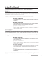 6
6
-
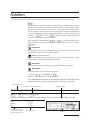 7
7
-
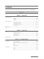 8
8
-
 9
9
-
 10
10
-
 11
11
-
 12
12
-
 13
13
-
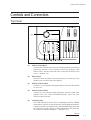 14
14
-
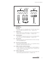 15
15
-
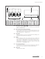 16
16
-
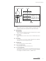 17
17
-
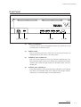 18
18
-
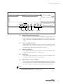 19
19
-
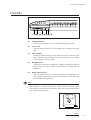 20
20
-
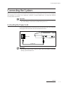 21
21
-
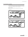 22
22
-
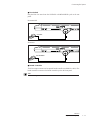 23
23
-
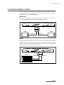 24
24
-
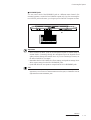 25
25
-
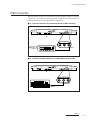 26
26
-
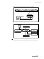 27
27
-
 28
28
-
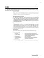 29
29
-
 30
30
-
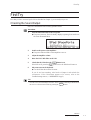 31
31
-
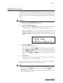 32
32
-
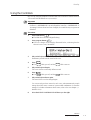 33
33
-
 34
34
-
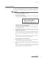 35
35
-
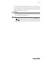 36
36
-
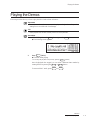 37
37
-
 38
38
-
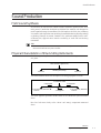 39
39
-
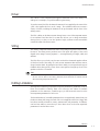 40
40
-
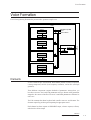 41
41
-
 42
42
-
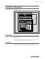 43
43
-
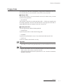 44
44
-
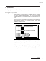 45
45
-
 46
46
-
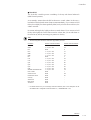 47
47
-
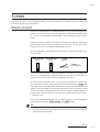 48
48
-
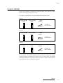 49
49
-
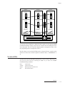 50
50
-
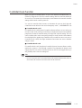 51
51
-
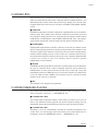 52
52
-
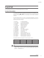 53
53
-
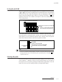 54
54
-
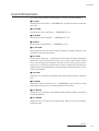 55
55
-
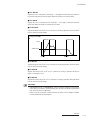 56
56
-
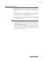 57
57
-
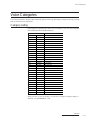 58
58
-
 59
59
-
 60
60
-
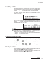 61
61
-
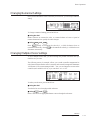 62
62
-
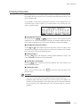 63
63
-
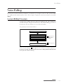 64
64
-
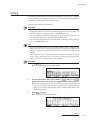 65
65
-
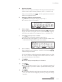 66
66
-
 67
67
-
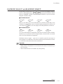 68
68
-
 69
69
-
 70
70
-
 71
71
-
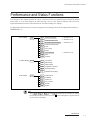 72
72
-
 73
73
-
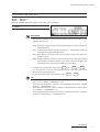 74
74
-
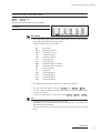 75
75
-
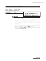 76
76
-
 77
77
-
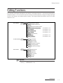 78
78
-
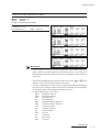 79
79
-
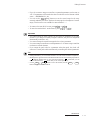 80
80
-
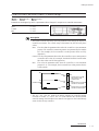 81
81
-
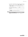 82
82
-
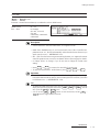 83
83
-
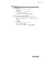 84
84
-
 85
85
-
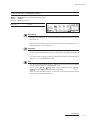 86
86
-
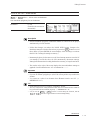 87
87
-
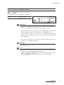 88
88
-
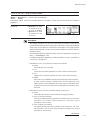 89
89
-
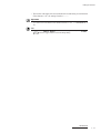 90
90
-
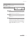 91
91
-
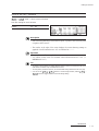 92
92
-
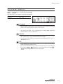 93
93
-
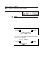 94
94
-
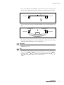 95
95
-
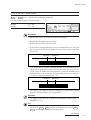 96
96
-
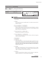 97
97
-
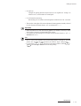 98
98
-
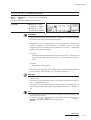 99
99
-
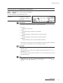 100
100
-
 101
101
-
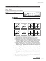 102
102
-
 103
103
-
 104
104
-
 105
105
-
 106
106
-
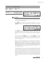 107
107
-
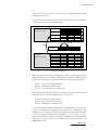 108
108
-
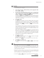 109
109
-
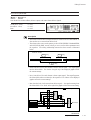 110
110
-
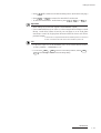 111
111
-
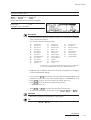 112
112
-
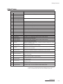 113
113
-
 114
114
-
 115
115
-
 116
116
-
 117
117
-
 118
118
-
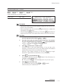 119
119
-
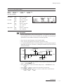 120
120
-
 121
121
-
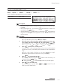 122
122
-
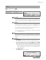 123
123
-
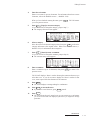 124
124
-
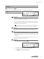 125
125
-
 126
126
-
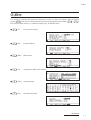 127
127
-
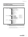 128
128
-
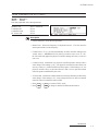 129
129
-
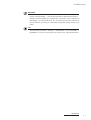 130
130
-
 131
131
-
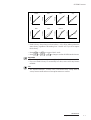 132
132
-
 133
133
-
 134
134
-
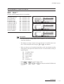 135
135
-
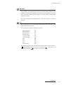 136
136
-
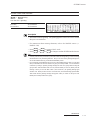 137
137
-
 138
138
-
 139
139
-
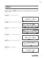 140
140
-
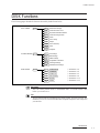 141
141
-
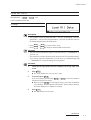 142
142
-
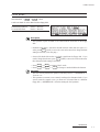 143
143
-
 144
144
-
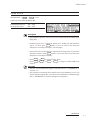 145
145
-
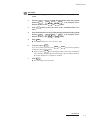 146
146
-
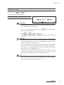 147
147
-
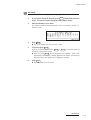 148
148
-
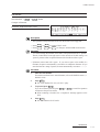 149
149
-
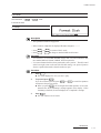 150
150
-
 151
151
-
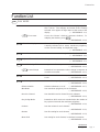 152
152
-
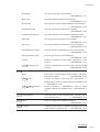 153
153
-
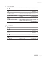 154
154
-
 155
155
-
 156
156
-
 157
157
-
 158
158
-
 159
159
-
 160
160
-
 161
161
-
 162
162
-
 163
163
-
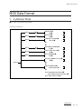 164
164
-
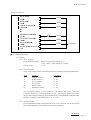 165
165
-
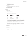 166
166
-
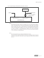 167
167
-
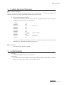 168
168
-
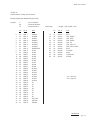 169
169
-
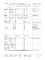 170
170
-
 171
171
-
 172
172
-
 173
173
-
 174
174


Yamaha VP1 El manual del propietario
- Categoría
- Sintetizador
- Tipo
- El manual del propietario
en otros idiomas
- français: Yamaha VP1 Le manuel du propriétaire
- italiano: Yamaha VP1 Manuale del proprietario
- English: Yamaha VP1 Owner's manual
- Deutsch: Yamaha VP1 Bedienungsanleitung
- русский: Yamaha VP1 Инструкция по применению
- Nederlands: Yamaha VP1 de handleiding
- português: Yamaha VP1 Manual do proprietário
- dansk: Yamaha VP1 Brugervejledning
- polski: Yamaha VP1 Instrukcja obsługi
- čeština: Yamaha VP1 Návod k obsluze
- svenska: Yamaha VP1 Bruksanvisning
- Türkçe: Yamaha VP1 El kitabı
- suomi: Yamaha VP1 Omistajan opas
- română: Yamaha VP1 Manualul proprietarului
Artículos relacionados
-
Yamaha GW10 El manual del propietario
-
-
-
-
-
-
-
-
-
