Pass and Seymour Floorbox and Tamper Resistant Finishing Kit Guía de instalación
- Tipo
- Guía de instalación

TradeMaster
®
Floorbox Description
The TM1542BOX for installation of electrical receptacles in wooden floors, where
required by National Electrical Code Standards, or for aesthetic preference. The
round floorbox is finished by a TM1542 finishing kit, (sold separately). Floorbox
can also accommodate low voltage wires, through the compartments provided.
Application
Floorbox is used to provide a place for electrical power in the floor, in an application
where it is difficult or impossible to provide power in the wall, but where it is required
by the NEC. The box can also be used to provide electrical power where it is desired
in the middle of the room, without the use of extension cords. The box can also be
used to provide access to low voltage communication wires.
Tamper-Resistant Finishing Kit Description and Application
The finishing kit is used to mount the electrical outlet in the TradeMaster
®
Floorbox,
(sold separately). The plastic cover is available in four different colors to blend into
your décor. The brass cover is available in two designs: A flush-mount version for
hardwood floors, and a raised flange version for carpeting, linoleum, etc. the outlet
is covered by a door which can be removed and replaced. When the outlet is not in
use, the door shuts for a flush finish. These covers are designed to be used only
with the TM1542BOX TradeMaster
®
Floorbox.
A 15 Amp, 125 Volt Tamper-Resistant outlet is included with the finishing kit. This
outlet meets NEC 406.11 requirment for Tamper-Resistant receptacles in
dwellings. The kit can be used with any decorator style device, such as a GFCI,
TVSS, or low voltage device. Low Voltage communication wires can also be
installed outside of the line voltage area by drilling holes in the cover as described
in these instructions.
AVAILABLE CATALOG #’s
Catalog # Description
TM1542BOX Round Wood Floorbox
TM1542TRBR Brown Finishing Kit with Brown
15 Amp, 125 Volt Tamper-Resistant Outlet
TM1542TRW White Finishing Kit with White
15 Amp, 125 Volt Tamper-Resistant Outlet
TM1542TRLA Light Almond Finishing Kit with Light Almond
15 Amp, 125 Volt Tamper-Resistant Outlet
TM1542TRGRY Gray/Paintable Finishing Kit with Gray
15 Amp, 125 Volt Tamper-Resistant Outlet
TM1542TRCF Brass Finishing Kit, Carpet Flange with Brown
15 Amp, 125 Volt Tamper-Resistant Outlet
TM1542TRFM Brass Finishing Kit, Flush Mount with Brown
15 Amp, 125 Volt Tamper-Resistant Outlet
Warning: Turn off all power to circuit before installing this device. Improper wiring
of any electrical device can cause serious injury or death. These wiring devices
should only be installed by an Electrician or other qualified person. Connect only
copper or copper-clad wire to the device in this package. Do not connect
aluminum wire to this device.
Wiring and floorbox installation must comply with the National Electrical
Code, and all applicable local codes.
As with any floor box, leaving the door open while not in use may result
in contamination of the installed wiring device, causing it to fail.
TradeMaster
®
TM1542-BOX
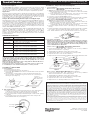
I. Box Installation
1. Determine the box location
2. Cut a 4 3/4" diameter hole into the sub-floor
3. Secure the TM1542-BOX to the sub-floor with the three screws provided.
(See Figure 1)
4. Lay finish floor over the sub-floor. The hole placed in the finish floor
cannot exceed 6" in diameter. Larger hole will not be covered by the
finishing kit. (See Figure 2)
II. Wire Installation
1. Pull the line voltage conductors through the boxʼs auto clamp openings
or the knockout openings located near the bottom of the box. If
knockouts are used, wire clamps are required (not supplied).
2. Cut line voltage wires, leaving a minimum length of 9" above the opening
of the box.
3. Low and line voltage cannot be installed in the same cavity per the
National Electrical Code. (See Figure 3)
TradeMaster
®
Tamper-Resistant Finishing Kit
I. Cover installation
Plastic Covers: TM1542TRBR, TM1542TRW, TM1542TRLA,
TM1542TRGRY
1. Optional low voltage feed-through applications: (See Figure 4)
a. Drill 3/8" diameter hole(s) in the cover. Drill hole locations are marked
on the bottom side of the cover.
b. Insert grommet(s) into the drilled holes and route the low voltage
communication wire(s) through the grommet opening(s).
2. Insert the cover into TM1542-BOX opening.
3. Fasten the adapter to the box with the four screws provided. Do not tighten
the screws to the point where the cover distorts (approx. 12 in-lbs).
Brass Covers: TM1542TRFM, TM1542TRCF
1. Optional low voltage feed-through applications: (See Figure 4)
a. Drill 3/8" diameter hole(s) in the brass flange. Drill hole locations are
indented on the bottom side of the brass flange.
b. Insert grommet(s) into the drilled holes and route the low voltage
communication wire(s) through the grommet opening(s).
2. Insert the adapter into the center of the flange (only if separated from
flange).
3. Fasten the adapter to the box with the four screws provided. Do not tighten
the screws to the point where the adapter distorts (approx. 12 in-lbs).
Note: TM1542TRFM cannot be used with finished floor thickness of less than 3/8".
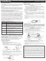
II. Receptacle Installation
Warning: Turn off all power to circuit before installing this device. Improper
wiring of any electrical device can cause serious injury or death. These wiring
devices should only be installed by an Electrician or other qualified person.
Connect only copper or copper-clad wire to the device in this package. Do not
connect aluminum wire to this device.
Plastic Covers: TM1542TRBR, TM1542TRW, TM1542TRLA,
TM1542TRGRY (See Figure 5)
1. If using the included outlet, strip conductors to 3/4". If using a different
device, follow instructions on package.
2. Terminate Ground, Neutral, and Hot wires in that order.
3. Install (attach) outlet to the cover with the two screws provided.
4. Snap the decorator cover over the outlet face.
5. Replace the door if removed during installation with a snap fit at the hinge area.
Brass Covers: TM1542TRFM, TM1542TRCF (See Figure 6)
1. If using the included outlet, strip conductors to 3/4". If using a different
device, follow instructions on the outlet package.
2. Terminate Ground, Neutral, and Hot wires in that order.
3. Install (attach) outlet to the cover with the two screws provided.
4. Snap the decorator cover over the outlet face.
5. Replace the door to the flange with the two screws provided.
Limited One Year Warranty
Pass & Seymour will remedy any defect in workmanship or material in Pass & Seymourʼs products
which may develop under proper and normal use within one year from date of purchase by a customer:
(1) by repair or replacement, or, at Pass & Seymourʼs option, (2) by return of an amount equal to
consumerʼs purchase price. Such remedy is IN LIEU OF ANY AND ALL EXPRESSED OR IMPLIED
WARRANTIES OF MERCHANTABILITY OR FITNESS FOR A PARTICULAR PURPOSE. Such remedy
by Pass & Seymour does not include or cover cost of labor for removal or reinstallation of the product.
ALL OTHER FURTHER ELEMENTS OF DAMAGE (INCIDENTAL OR CONSEQUENTIAL DAMAGES)
FOR BREACH OF ANY AND ALL EXPRESSED OR IMPLIED WARRANTIES INCLUDING
WARRANTIES OF MERCHANTABILITY OR FITNESS FOR A PARTICULAR PURPOSE ARE
EXCLUDED HEREBY. (Some states do not allow disclaimer or exclusion or limitation of incidental or
consequential damages, so the above disclaimers and limitation or exclusion may not apply to you. ANY
IMPLIED WARRANTIES INCLUDING WHERE REQUIRED WARRANTIES OF MERCHANTABILITY
OR FITNESS FOR A PARTICULAR PURPOSE SHALL BE LIMITED TO THE ONE YEAR PERIOD SET
FORTH ABOVE. (Some states do not allow limitations on how long implied warranty lasts, so the above
limitation may not apply to you.)
To insure safety, all repairs to Pass & Seymour products must be made by Pass & Seymour, or under
specific direction. Procedure to obtain performance of any warranty obligation is as follows: (1) Contact
Pass & Seymour, Syracuse, NY 13221, for instructions concerning return or repair; (2) return the
product to Pass & Seymour, postage paid, with your name and address and a written description of
the installation or use of the Pass & Seymour product, and the observed defects or failure to operate,
or other claimed basis for dissatisfaction
.
Floorbox and Tamper Resistant Finishing Kit
Installation Instructions
Figure 3
Low Voltage
Line Voltage
Figure 4
Grommets
Drill Hole
Locations
Figure 1
Sub floor
Figure 2
Finish floor
(Opening must be
less than 6" dia.)
Door
Decorator Cover
Tamper-Resistant
Receptacle
Cover
O Ring
Adapter
Flange
©2010 Pass & Seymour/Legrand
P.O. Box 4822, Syracuse, NY 13221
P/N 340906
Figure 5 Figure 6

Descripción de Caja de Piso
El TM1542BOX para instalación de enchufes eléctricos en pisos de madera,
donde es requerido por los estándares del Código Eléctrico Nacional o por
preferencia estética. La caja de piso redonda se termina con el juego de últimos
toques TM1542 (vendido por separado). Caja de Piso también puede acomodar
cables de bajo voltaje, a través de los compartimientos proveídos.
Aplicación
Caja de Piso se utiliza para proveer un lugar con electricidad en el piso, en una
aplicación donde es difícil o imposible proveer electricidad en la pared pero donde
es requerida por el NEC. La caja también se puede utilizar para proveer electricidad
donde se desee en el medio de un cuarto, sin una extensión. La caja también se
puede utilizar para proveer acceso a cableado de comunicación de bajo voltaje.
Descripcion y Aplicacion del Juego de Últimos Toques
Resistente a la Manipulación Indebida
El juego de terminación se utiliza para montar el enchufe eléctrico en la Caja de
Piso TradeMaster
®
(vendida separadamente). La tapa de plástico está disponible
en cuatro colores diferentes para lucir mejor en su ambiente de uso. La tapa de
latón está disponible con dos diseños: versión de montaje al ras para pisos de
madera y versión con alas para alfombras, linóleo, etc. El enchufe esta cubierto por
una puerta que puede ser quitada y reemplazada. Cuando el enchufe no se está
usando, la puerta cierra para una terminación en línea. Estas tapas están diseñadas
para ser usadas solamente con la caja de piso TradeMaster
®
TM1542BOX.
Con el kit de acabado, se incluye un tomacorriente resistente a la manipulación
indebida de 15 Amperios, 125 Voltios. Este tomacorriente cumple la norma NEC
406.11 para tomacorrientes resistentes a la manipulación indebida en casas. El
kit puede utilizarse con cualquier dispositivo estilo decorativo, tal como GFCI,
supresores de sobrevoltajes transitorios (TVSS) o dispositivos de bajo voltaje.
También pueden instalarse alambres de comunicación de bajo voltaje por fuera
del área de voltaje de línea taladrando orificios en la cubierta tal como se
describe en estas instrucciones.
NUMEROS DE CATÁLOGOS DISPONIBLES
N° de Catalogo Descripción
TM1542BOX
Caja redonda para piso de madera
TM1542TRBR Kit de acabado color café con tomacorriente resistente a
la manipulación indebida color café, 15 Amperios, 125 Voltios
TM1542TRW Kit de acabado color blanco con tomacorriente resistente
a la manipulación indebida color blanco, 15 Amperios,
125 Voltios
TM1542TRLA Kit de acabado color almendra claro con tomacorriente
resistente a la manipulación indebida color almendra
claro, 15 Amperios, 125 Voltios
TM1542TRGRY Kit de acabado color gris/pintable con tomacorriente
resistente a la manipulación indebida color gris,
15 Amperios,125 Voltios
TM1542TRCF Kit de acabado color dorado, reborde para alfombra, con
tomacorriente resistente a la manipulación indebida color
café, 15 Amperios, 125 Voltios
TM1542TRFM Kit de acabado color dorado, montaje al ras, con
tomacorriente resistente a la manipulación indebida color
café, 15 Amperios, 125 Voltios
Advertencia: Apague todos los circuitos antes de instalar este aparato. Un
alambrado incorrecto de cualquier aparato eléctrico puede causar daños
serios o muertes. Estos aparatos debían instalarse solamente por un
electricista u otra persona calificada. Conecte únicamente cables de cobre
o revestidos de cobre al aparato en este paquete. No conecte cables de
aluminio a este aparato.
Cableado e instalación de la caja de piso tiene que cumplir con el Código
Eléctrico Nacional y todos los códigos locales aplicables.
Como con cualquier caja de piso, el dejar la puerta abierta mientras no se
esté usando resultará en contaminación del dispositivo eléctrico
instalado, causándole fallas.
TradeMaster
®
TM1542-BOX
I. Instalación de la Caja
1. Determine la localización de la caja.
2. Corte un hueco de 4 3/4" de diámetro en el sub-piso.
3. Asegure el TM1542-BOX al sub-piso con los tres tornillos proveídos.
(Véase la Figura 1)
4. Ponga el piso terminado sobre el sub-piso. El hueco hecho en el piso
terminado no puede pasarse de 6" de diámetro. Huecos mas grandes no
serán cubiertos por el juego de Ultimos Toques. (Véase la Figura 2)
II. Instalación de Cables
1. Hale los conductores de voltaje de línea a través del las aperturas de
grámpas automáticas o los discos removibles en la parte de abajo de la
caja. Si los huecos de destapaderos se utilizan, grapas de cable son
requeridas (no suministradas).
2. Corte los cables de voltaje de línea, dejando un largo de 9" por en cima
de la apertura de la caja.
3. Bajo voltaje y voltaje de línea no puede instalarse en la misma cavidad de
acuerdo con el Código Eléctrico Nacional. (Véase la Figura 3)
TradeMaster
®
Juego de Últimos Toques Resistente a la
Manipulación Indebida
I. Instalación de Tapa
Tapas de Plástico: TM1542TRBR, TM1542TRW, TM1542TRLA,
TM1542TRGRY
1. Aplicaciones de bajo voltaje de pase Opcionales (Véase la Figura 4)
a. Taladre hueco(s) de 3/8" de diámetro en la tapa. Marcas para taladrar los
huecos están en la parte de abajo de la tapa.
b. Inserte la(s) arandela(s) de cabo en los huecos taladrados y meta los
cables de bajo voltaje por los huecos de la(s) arandela(s).
2. Ponga la tapa en la apertura del TM1542-BOX.
3. Fije la tapa a la caja con los cuatro tornillos proveídos. No apriete los
tornillos tanto que distornsionen el adaptador (aproximadamente 12 in-lbs).
Tapas de Latón: TM1542TRFM, TM1542TRCF
1. Aplicaciones opcionales de bajo voltaje y con continuacion: (Vease la
Figura 4)
a. Taladre hueco(s) de 3/8" de diametro en el ala de latón. La localización
de los huecos están indentados en la parte de abajo del ala de latón.
b. Inserte la(s) arandela(s) de cabo en los huecos taladrados y encamine
lo(s) cable(s) de comunicaciones de bajo voltaje a través de la(s)
apertura(s) en las arandela(s).
2. Inserte el adaptador en el centro de la arandela de cabo (solo si separado
del ala).
3. Asegure el adaptador a la caja con los cuatro tornillos proveidos. No apriete
los tornillos tanto que distornsionen el adapta dor (aproximadamente
12 in-lbs).
Nota: TM1542TRFM no puede ser usado con pisos terminados con grueso de
menos de 3/8".
II. Instalación de Enchufe
Advertencia: Apague todos los circuitos antes de instalar este aparato.
El alambrado incorrecto de cualquier aparato eléctrico puede causar
daños serios o muertes. Estos aparatos debían instalarse solamente por
un electricista u otra persona calificada. Conecte únicamente cables de
cobre o revestidos de cobre al aparato en este paquete. No conecte
cables de aluminio a este aparato.
Tapas de Plástico: TM1542TRBR, TM1542TRW, TM1542TRLA,
TM1542TRGRY (Véase la Figura 5)
1. Si utiliza el enchufe incluido, pele los conductores 3/4". Si utiliza un
dispositivo diferente, siga las instrucciones en el paquete.
2. Conecte la Tierra, Neutral y Cargado en ese orden.
3. Instale (fije) el enchufe a la tapa con los dos tornillos proveídos.
4. Enganche la tapa decoradora sobre el frente del enchufe.
5. Reemplace la puerta si se quitó durante la instalación con una entrada de
resorte en la parte de la visagra.
Tapas de Latón: TM1542TRFM, TM1542TRCF (Véase la Figura 6)
1. Si utiliza el enchufe incluido, pele los conductores a 3/4". Si utiliza otro
dispositivo, siga las instrucciones en la caja del enchufe.
2. Conecte la Tierra, Neutral y Cargado en ese orden.
3. Instale (ponga) el enchufe en la caja con los dos tornillos proveidos.
4. Apriete hasta que tranque, la tapa decoradora, sobre la parte de alante
del enchufe.
5. Ponga la tapa en el ala con los dos tornillos proveidos.
Garantía Limitada De Un Año
Pass & Seymour remediara cualquier defecto en la manufactura o material de productos Pass &
Seymour que ocurran durante un apropiado y normal uso, dentro de un ano de la fecha de la compra
por un cliente:
(1) por reparación o reemplazo o, según opción de Pass & Seymour, (2) por devolución de una cantidad
igual al precio de compra por el consumidor. Tal remedio es EN LUGAR DE CUALQUIERA Y TODAS
LAS GARANTIAS EXPRESADAS O IMPLICITAS DE LA MERCANTIBILIDAD O USO APROPIADO A UN
PROPOSITO PARTICULAR. Tal remedio por Pass & Seymour no incluye o cubre el costo de mano de
obra por la remoción o reinstalación del producto. TODOS LOS DEMAS ELEMENTOS (INCIDENTALES
O CONSECUENTES) DE DANO POR INCUMPLIMIENTO DE CUALQUIER Y TODAS LAS GARANTIAS
EXPRESAS O IMPLICITAS INCLUYENDO GARANTIAS DE MERCANTIBILIDAD O USO APROPIADO A
UN PROPOSITO PARTICULAR ESTAN POR TANTO EXCLUIDAS. (En algunos estados este acápite
excluyente o limitante de danos incidentales o consecuentes no es permitido, así que los excluyentes y
limitantes arriba mencionados pueden no ser aplicables a Ud.) CUALQUIER GARANTIA IMPLICITA
INCLUYENDO LAS REQUERIDAS PARA MERCANTIBILIDAD O USO APROPIADO PARA UN
PROPOSITO PARTICULAR SERAN LIMITADAS AL PERIODO DE UN ANO ARRIBA EXPRESADO.
(Algunos estados no permiten limitaciones sobre la longitud la garantía implícita durara, por tanto la
limitación arriba expresada podrá no ser aplicable a Ud.). Para asegurar la seguridad, todas las
reparaciones a los productos Pass & Seymour deben ser hechas por Pass & Seymour, o bajo su
especifica dirección. El procedimiento para obtener cumplimiento de cualquier obligación de la garantía
es tal y como sigue: (1) Contacte Pass & Seymour, Syracuse, New York 13221, para instrucciones
concernientes a la devolución o reparación; (2) devuelva el producto a Pass & Seymour, con el franqueo
pagado, con su nombre y dirección y una descripción escrita de la instalación o el uso del producto
Pass & Seymour, y de los defectos observados o las fallas de operación, u otra base para reclamar su
insatisfacción.
TradeMaster
®
Caja de Piso y Juego de Últimos Toques Resistente a la Manipulación Indebida
Instrucciones de Instalación
Figura 4
Arandelas
de Cabo
Localización
de Huecos
Figura 1
Sub Piso
Figura 2
Piso Terminado (Hueco debe
ser menos de 6" dia.)
Figure 3
de Bajo Voltaje
Voltaje de Línea
Puerta
Tapa Decoradora
Tomacorriente de
una salida resistente
a la manipulación indebida
Tapa
Junta
Adaptador
Ala
Figure 5 Figure 6
-
 1
1
-
 2
2


Pass and Seymour Floorbox and Tamper Resistant Finishing Kit Guía de instalación
- Tipo
- Guía de instalación
en otros idiomas
Artículos relacionados
-
Pass and Seymour TM1542BOX Guía de instalación
-
Legrand Extra Duty Rated Weatherproof While-In-Use Cover Guía de instalación
-
-
-
-
Legrand TLV603LA Guía de instalación
-
-
-
Legrand LSCL450W Guía de instalación