Commercial Electric 74202/HD Guía de instalación
- Tipo
- Guía de instalación

THANK YOU
We appreciate the trust and condence you have placed in Commercial Electric through the purchase of this LED Flat Panel Fixture. We strive
to continually create quality products designed to enhance your home. Visit us online to see our full line of products available for your home
improvement needs. Thank you for choosing Commercial Electric!
USE AND CARE GUIDE
4 IN. ROUND FLAT PANEL WITH
SELECTABLE COLOR TEMPERATURES
Questions, problems, missing parts? Before returning to the store,
call Commercial Electric Customer Service
8 a.m. - 7 p.m., EST, Monday - Friday, 9 a.m. - 6 p.m., EST, Saturday
1-877-527-0313
HOMEDEPOT.COM
SKU #1002 632 069
Model #74202/HD

2
Table of Contents
Table of Contents ...................................2
Safety Information ..................................2
Warranty ..........................................2
Pre-Installation .....................................3
Tools Required ....................................3
Hardware Included .................................3
Installation ...................................... 4-6
Changing the Color Settings ..........................7
Safety Information
For your safety, always remember to:
□ Turn off the power supply at the fuse or circuit breaker box
before you install the fixture.
□ Ground the fixture to avoid potential electric shock and to ensure
reliable starting.
□ Double-check all connections to be sure they are
tight and correct.
□ Wear rubber soled shoes and work on a sturdy
wooden ladder.
□ Account for small parts and destroy packing material, as these
may be hazardous to children.
This fixture is designed for use in a circuit protected by a fuse or
circuit breaker. It is also designed to be installed in accordance with
local electrical codes. If you are unsure about your wiring, consult a
qualified electrician or local electrical inspector, and check your local
electrical code.
WARNING: RISK OF SHOCK. House electric current can
cause painful shock or serious injury unless handled properly.
CAUTION: Turn off the main power at the circuit breaker
before installing the fixture, in order to prevent possible shock.
NOTICE: All electrical connections must be in accordance with local
and National Electrical Code (N.E.C.) standards. If you are unfamiliar
with proper electrical wiring connections obtain the services of a
qualified electrician.
Remove the fixture and the mounting package from the box and make
sure that no parts are missing by referencing the illustrations on the
installation instructions.
Warranty
LIMITED WARRANTY
This product is warranted to be free from defects in workmanship and materials for up to 5 years from date of purchase. If it fails to do so,
please contact the Customer Service Team at 1-877-527-0313 or visit www.HomeDepot.com.
WARNING: Risk of fire. Use only on 120 volt 60Hz
circuits. Suitable for damp locations. Before installing
your lighting fixture, thoroughly review enclosed in-
stallation manual. If you do not have sufficient elec-
trical wiring experience, please refer to a do-it-your-
self wiring handbook or have your fixture installed by
a qualified licensed electrician. All electrical connec-
tions must be in accordance with Local and National
Electrical Code (NEC) Standards. If flickering occurs
in low level dimming, increase light level. Compatible
with most dimmers including Leviton 6681-IW, Lutron
S-600P and Lutron DVCL-153. Dimmable to 10% with
most dimmers.
FCC STATEMENT
This device complies with part 15 of the FCC Rules. Operation is subject to the following
two conditions:
(1) This device may not cause harmful interference, and (2) this device must accept
any interference received, including interference that may cause undesired operation.
Note: This equipment has been tested and found to comply with the limits for a Class B
digital device, pursuant to part 15 of the FCC Rules. These limits are designed to provide
reasonable protection against harmful interference in a residential installation. This
equipment generates, uses and can radiate radio frequency energy and, if not installed
and used in accordance with the instructions, may cause harmful interference to radio
communications. However, there is no guarantee that interference will not occur in a
particular installation. If this equipment does cause harmful interference to radio or
television reception, which can be determined by turning the equipment off and on, the
user is encouraged to try to correct the interference by one or more of the following
measures: Reorient or relocate the receiving antenna. Increase the separation between
the equipment and receiver. Connect the equipment into an outlet on a circuit different
from that to which the receiver is connected. Consult the dealer or an experienced radio/
TV technician for help.

3 HOMEDEPOT.COM
Please contact 1-877-527-0313 for further assistance.
Pre-Installation
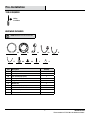
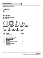
TOOLS REQUIRED
HARDWARE INCLUDED
NOTE: Hardware not shown to actual size.
Phillips
screwdriver
AA BB CC DD EE
FF GG
HH II JJ
Part Description Quantity
AA 5 in. fixture 1
BB Mounting bracket 1
CC 4 in. mounting clip spring 3
DD E26 adapter with male connector 1
EE Stripped wires with male connector 1
FF Ground wire 1
GG 4 in. mounting clip spring screws 3
HH Ground wire screw 1
II J-Box mounting screws 2
JJ Wire nuts 3

4
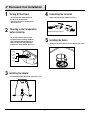
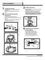
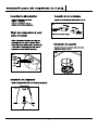
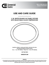
4” Recessed Can Installation
1
Turning Off the Power
2
Choosing a color temperature
before installing
□ Turn the power OFF at the switch and
fusebox or the circuit breaker.
□ Remove the existing trim installed in the
recessed housing.
□ Use the slide switch to choose a color
temperature before installing. Soft White
(SW), Bright White (BW), Daylight (DL) or
choose to adjust the color temperature
from the wall switch (SWITCH) (See Fig.1).
□ Install the E26 adapter (DD) into the socket (See Fig. 2).
3
Installing the adapter
□ Connect the two terminals together. (See Fig. 3)
□ Gently push the fixture into the recessed housing. (See Fig. 4)
4
Connecting the terminals
5
Installing the fixture
Soft White
3000K
Bright White
4000K
Daylight
5000K
Switch*
Fig. 1
Fig. 3
DD
Fig. 2
Connect the orange connectors
Fig. 4

5 HOMEDEPOT.COM
Please contact 1-877-527-0313 for further assistance.
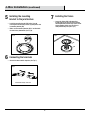
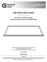
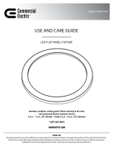
J-Box Installation
□ Use the slide switch to choose a color
temperature before installing. Soft White
(SW), Bright White (BW), Daylight (DL) or
choose to adjust the color temperature
from the wall switch (SWITCH) (See Fig. 5).
Soft White
3000K
Bright White
4000K
Daylight
5000K
Switch*
Fig. 5
1
Turning Off the Power
2
Disconnecting and removing
components
3
Identifying the wires
4
Choosing a color temperature
before installing
□ Turn the power OFF at the switch and fusebox or the
circuit breaker.
□ Remove the existing trim installed in the recessed
housing.
□ Disconnect the E26 adapter (DD) (See Fig.1).
□ Remove the mounting bracket (BB) from the fixture (AA).
(See Fig. 2).
□ Remove the 4 in. mounting clip springs (CC) from the
mounting bracket (BB) (See Fig. 3).
□ Identify the wiring: (black - line voltage, white - neutral
and green - ground)
□ Connect the green ground wire (FF) to the mounting
plate (BB). Use the wire nuts (JJ) to connect the
stripped wires of the male connector (EE) to the two
wires coming from the J-box (black - line voltage, white
- neutral). Connect the ground wire in the J-box to the
green wire on the mounting plate (BB). See figure 4.
Fig.1
Fig. 2
Fig. 3
Fig. 4
EE
BB
JJ
FF
CC
DD
BB
AA

6
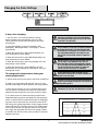
J-Box Installation (continued)
□ Connect the two terminals together. (See Fig. 7).
5
Installing the mounting
bracket to the junction box
6
Connecting the terminals
7
Installing the fixture
□ Install the mounting bracket (BB) to the J-box by
inserting the two mounting screws (II) through the slots
in mounting bracket (BB).
□ Make sure the mounting bracket (BB) is installed with
the label facing downwards (See Fig. 6).
Fig. 7
Fig. 8Fig. 6
Connect the orange connectors
□ Secure the fixture (AA) to the mounting
bracket (BB) by pressing the fixture into the
mounting bracket until the clips on the fixture
engage together. Make sure the fixture is
firmly locked into place (See Fig. 8).
BB
AA
II

7 HOMEDEPOT.COM
Please contact 1-877-527-0313 for further assistance.
Changing the Color Settings
4-way color changing:
1. You can lock in one color temperature, change
among multiple color temperatures, dim from 10%-
100%, memorize the last color temperature and reset
automatically.
2. Light Switch Marks on the lamp represent: SW
(Soft White) - BW (Bright White) - DL (Daylight) - Switch
(Light Switch)
3. When the slide switch is set to SW (Soft White), the
color temperature is set at 3000K.
4. When the slide switch is set to BW (Bright White), the
color temperature is set at 4000K.
5. When the slide switch is set to DL (Daylight), the color
temperature is set at 5000K.
6. When the slide switch is set to SWITCH, the color
temperature can be changed from SW-BW-DL with your
existing light switch.
NOTICE: The toggle switch is located on the back of the xture.
To change color temperatures using your
existing light switch:
A. Set the slide switch on the back of the xture to SWITCH.
B. Toggle your light switch ON and OFF within 0.5-3 sec-
onds to cycle though the three dierent color temperatures.
C. If the xture is left On for over 10 seconds then turned
OFF, the xture will remember the last color temperature
selected and will display that color when turned on again.
D. The reset function is used when using multiple Color
Selectable lighting products operating from the same light
switch. In the event that multiple xtures are not displaying
the same color at the same time, the xtures must be RE-
SET using your existing light switch. Simply toggle the wall
switch ON and OFF ve times, leaving it in the ON position
for 5 second intervals. (ex: With the xture in the ON posi-
tion, toggle the wall switch OFF then ON, leaving it ON for
5 seconds, then OFF then ON, leaving it ON for 5 seconds.
(Repeat ve times.)
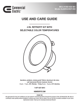
22
8
3.1
0.9
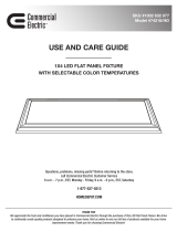
Center Beam
(Foot Candles) Beam Diameter
Beam Angle = 114º
LIGHTING DISTRIBUTION
3 ft 9.2 ft
15 ft
24 ft
46 ft
5 ft
8 ft
15 ft
WARNING: CHANGES OR MODIFICATIONS NOT
EXPRESSLY APPROVED BY THE PARTY RESPONSIBLE
FOR COMPLIANCE COULD VOID THE USER’S AUTHORITY
TO OPERATE THE EQUIPMENT.
WARNING: RISK OF FIRE OR ELECTRIC SHOCK.
INSTALLATION OF THIS RETROFIT ASSEMBLY REQUIRES
A PERSON FAMILIAR WITH THE CONSTRUCTION AND
OPERATION OF THE LUMINAIRE’S ELECTRICAL SYSTEM
AND THE HAZARD INVOLVED. IF NOT QUALIFIED, DO
NOT ATTEMPT INSTALLATION. CONTACT A QUALIFIED
PERSON.
WARNING: RISK OF FIRE OR ELECTRIC SHOCK. INSTALL
THIS KIT ONLY IN THE LUMINAIRES THAT HAS THE
CONSTRUCTION FEATURES AND DIMENSIONS SHOWN
IN THE PHOTOGRAPHS AND/OR DRAWINGS AND WHERE
THE INPUT RATING OF THE RETROFIT KIT DOES NOT
EXCEED THE INPUT RATING OF THE LUMINAIRE.
DO NOT MAKE OR ALTER ANY OPEN HOLES IN AN
ENCLOSURE OF WIRING OR ELECTRICAL COMPONENTS
DURING KIT INSTALLATION.
WARNING: TO PREVENT WIRING DAMAGE OR ABRASION,
DO NOT EXPOSE WIRING TO EDGES OF SHEET METAL OR
OTHER SHARP OBJECTS.
THIS DEVICE IS NOT INTENDED FOR USE WITH
EMERGENCY EXITS OR NOT FOR EMERGENCY LIGHTING.

Questions, problems, missing parts? Before returning to the store,
call Commercial Electric Customer Service
8 a.m. - 7 p.m., EST, Monday - Friday, 9 a.m. - 6 p.m., EST, Saturday
1-877-527-0313
HOMEDEPOT.COM
Retain this manual for future use.


2
Tabla de contenidos
Información de Seguridad
Garantía

3 HOMEDEPOT.COM
Comuníquese con el 1-877-527-0313 para obtener más ayuda.
Pre-instalación

4

5 HOMEDEPOT.COM
Comuníquese con el 1-877-527-0313 para obtener más ayuda.
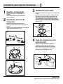
Instalación para caja de conexiones
□ Utilice el interruptor deslizante para elegir una
temperatura de color antes de instalar. Blanco
Suave (SW), Blanco Brillante (BW), Luz de Dia (DL)
o elegir ajustar la temperatura del color desde el
interruptor de pared (SWITCH) (Ver Fig. 5).
Fig. 5
1
Desactivar la alimentación
2
Desconexión y extracción de
componente
3
Identificación de los cables
4
Elegir una temperatura de color
antes de instalar
□ Apague el interruptor y la caja de fusibles o el
disyuntor.
□ Quite el revestimiento existente instalado en la
carcasa empotrada.
□ Desconecte el adaptador E26 (DD) (ver Fig.1).
□ Retire el soporte de montaje (BB) del aparato (AA) (vea
la Fig. 2).
□ Retire los resortes de clip de montaje de 4 pulg. (CC) del
soporte de montaje (BB) (Vea la Fig. 3).
□ Identifique el cableado: (línea negra, blanco - neutro y verde
- tierra).
□ Conecte el cable de tierra verde (FF) a la placa de montaje
(BB). Utilice las tuercas de cable (JJ) para conectar los
cables desmontados del conector macho (EE) a los dos
cables procedentes de la caja de conexiones (tensión de
línea negra, blanco - neutro). Conecte el cable de tierra en
el caja de conexiones al cable verde en la placa de montaje
(BB). (ver Fig. 4).
Fig.1
Fig. 2
Fig. 3
Fig. 4
EE
BB
JJ
FF
CC
DD
BB
AA
Blanco Suave
3000K
Blanco Brillante
4000K
Luz de Dia
5000K
Cambiar*

6
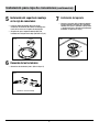
Instalación para caja de conexiones (continuación)
□ Conecte los dos terminales juntos. (Véase la figura 7).
5
Instalación del soporte de montaje
en la caja de conexiones
6
Conexión de los terminales
7
Instalación del aparato
□ Instale el soporte de montaje (BB) en la caja de
conexiones insertando los dos tornillos de montaje (II) a
través de las ranuras en el soporte de montaje (BB).
□ Asegúrese de que el soporte de montaje (BB) esté
instalado con la etiqueta hacia abajo (consulte la Fig. 6).
Fig. 7
Fig. 8Fig. 6
Conecte los conectores naranja
□ Asegure el accesorio (AA) al soporte de montaje
(BB) presionando el accesorio en el soporte de
montaje hasta que los sujetadores encajen entre
sí. Asegúrese de que el aparato esté firmemente
trabado en su lugar (vea la Fig. 8).
BB
AA
II

7 HOMEDEPOT.COM
Comuníquese con el 1-877-527-0313 para obtener más ayuda.
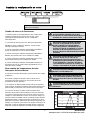
DARSE CUENTA: El interruptor de palanca se encuentra en la
parte trasera del aparato.
22
8
3.1
0.9
Cambio de color en 4 direcciones:
1. Puede bloquear en una temperatura de color, cambiar entre
múltiples temperaturas de color, iluminar de 10% -100%,
memorizar la última temperatura de color y restablecer
automáticamente.
2. Las marcas de interruptor de luz en la lámpara representan:
SW (Blanco Suave) - BW (blanco brillante) - DL (luz del día) -
interruptor (interruptor de la luz)
3. Cuando el interruptor deslizante está ajustado a SW (Blanco
Suave), la temperatura de color se ajusta a 3000K.
4. Cuando el interruptor deslizante está ajustado a BW (Blanco
Brillante), la temperatura de color se establece en 4000K.
5. Cuando el interruptor deslizante está ajustado a DL (Luz de
Dia), la temperatura de color se establece en 5000K.
6. Cuando el interruptor deslizante está ajustado a SWITCH, la
temperatura de color se puede cambiar de SW-BW-DL con el
interruptor de luz existente.
Para cambiar las temperaturas de color
Interruptor de luz existente:
A. Coloque el interruptor deslizante en la parte trasera de la unidad
en SWITCH.
B. Encienda y apague el interruptor de la luz dentro de 0.5-
3 segundos para hacer funcionar el ciclo a través de las tres
temperaturas de color diferentes.
C. Si el aparato se deja encendido durante más de 10 segundos y
luego se apaga, el aparato recordará la última temperatura de color
seleccionada y mostrará ese color cuando vuelva a encenderse.
D. La función de reinicio se utiliza cuando se utilizan varios
productos de iluminación seleccionables por color que funcionan
con el mismo interruptor de luz. En el caso de que los accesorios
múltiples no estén exhibiendo el mismo color al mismo tiempo, los
accesorios deben ser RESET usando su interruptor ligero existente.
Simpliemente apage y prenda el interruptor de pared cinco veces,
dejándolo en la posición ON durante intervalos de 5 segundos. (Por
ejemplo: Con el aparato en la posición ON, apague el interruptor de
pared OFF y luego ON, dejándolo encendido durante 5 segundos,
luego OFF y luego ON, dejándolo encendido durante 5 segundos.
ADVERTENCIA: LOS CAMBIOS O MODIFICACIONES
NO EXPRESAMENTE APROBADOS POR LA PARTE
RESPONSABLE DEL CUMPLIMIENTO PUEDEN ANULAR LA
AUTORIDAD DEL USUARIO PARA OPERAR EL EQUIPO.
ADVERTENCIA: RIESGO DE INCENDIO O DESCARGA
ELÉCTRICA. LA INSTALACIÓN DE ESTE MONTAJE
RETROFIT REQUIERE UNA PERSONA FAMILIAR
CON LA CONSTRUCCIÓN Y FUNCIONAMIENTO DEL
SISTEMA ELÉCTRICO DE LA LUMINARIA Y EL PELIGRO
IMPLICADO. SI NO ESTÁ CALIFICADO, NO INTENTE
INSTALAR. PÓNGASE EN CONTACTO CON UNA PERSONA
CALIFICADA.
ADVERTENCIA: RIESGO DE INCENDIO O DESCARGA
ELÉCTRICA. INSTALE ESTE KIT SÓLO EN LOS
LUMINARIOS QUE TIENEN LAS CARACTERÍSTICAS Y
DIMENSIONES DE CONSTRUCCIÓN QUE SE MUESTRAN
EN LAS FOTOGRAFÍAS Y / O DIBUJOS Y EN LOS QUE
LA CALIFICACIÓN DE ENTRADA DEL KIT RETROFIT NO
EXCEDA LA CALIFICACIÓN DE ENTRADA DEL LUMINARIO.
NO HAGA NI ALTERE NINGUN AGUJERO ABIERTO EN UN
RECINTO DE CABLEADO O COMPONENTES ELÉCTRICOS
DURANTE LA INSTALACIÓN DEL KIT.
ADVERTENCIA: PARA PREVENIR DAÑOS O ABRASIÓN
EN EL CABLEADO, NO EXPONGA EL CABLEADO A LOS
BORDES DE HOJAS METALICAS O DE OTROS OBJETOS
AFILADOS.
ESTE DISPOSITIVO NO ESTÁ DESTINADO PARA USO CON
SALIDAS DE EMERGENCIA NI PARA ILUMINACIÓN DE
EMERGENCIA.

-
 1
1
-
 2
2
-
 3
3
-
 4
4
-
 5
5
-
 6
6
-
 7
7
-
 8
8
-
 9
9
-
 10
10
-
 11
11
-
 12
12
-
 13
13
-
 14
14
-
 15
15
-
 16
16


Commercial Electric 74202/HD Guía de instalación
- Tipo
- Guía de instalación
en otros idiomas
Artículos relacionados
-
 Commercial Electric 74204/HD Guía de instalación
-
Commercial Electric 74206/HD Guía de instalación
-
 Commercial Electric 74210/HD/3 Guía de instalación
-
 Commercial Electric 53805301 Guía de instalación
-
 Commercial Electric 53198101 Guía de instalación
-
 Commercial Electric 74048/HD Manual de usuario
-
 Commercial Electric FP1X4/4WY/WH/HD/2 Guía de instalación
-
 Feit Electric 74218 Guía de instalación
-
 Commercial Electric 74047/HD Manual de usuario
-
 Commercial Electric LEDR4/4WY/HD Guía de instalación


