Dell PowerSwitch N1500 Series Guía de inicio rápido
- Categoría
- Conmutadores de red
- Tipo
- Guía de inicio rápido

Dell Networking
N1500 Series Switch
Getting Started Guide
Guide de mise en route
Handbuch zum Einstieg
Руководство по началу работы
Priručnik za početak rada
Guía de introducción
Başlangıç Kılavuzu
הדובע תליחת ךירדמ


Dell Networking
N1500 Series Switch
Getting Started Guide
Regulatory Models: N1524, N1524P,
N1548, N1548P

Notes, Cautions, and Warnings
NOTE: A NOTE indicates important information that helps you make better use of
your switch.
CAUTION: A CAUTION indicates either potential damage to hardware or loss of
data and tells you how to avoid the problem.
WARNING: A WARNING indicates a potential for property damage, personal
injury, or death.
____________________
Copyright © 2015 Dell Inc. All rights reserved. This product is protected by U.S. and international
copyright and intellectual property laws. Dell™ and the Dell logo are trademarks of Dell Inc. in the
United States and/or other jurisdictions. All other marks and names mentioned herein may be
trademarks of their respective companies.
2015-05 P/N M25TN Rev. A00

Contents 5
Contents
1 Introduction. . . . . . . . . . . . . . . . . . . . . . . . 7
2 Dell Networking N1500 Series Overview . . . 7
3 Hardware Overview. . . . . . . . . . . . . . . . . . 8
Dell Networking N1500 Series Front Panel . . . . . . . . 8
Switch Ports
. . . . . . . . . . . . . . . . . . . . 10
Console Port
. . . . . . . . . . . . . . . . . . . . 11
USB Port
. . . . . . . . . . . . . . . . . . . . . . 11
Reset Button . . . . . . . . . . . . . . . . . . . . 11
Port and System LEDs
. . . . . . . . . . . . . . . 12
Stack Master LED and Stack Number Display
. . . 12
Dell Networking N1500 Series Back Panel
. . . . . . . 13
Power Supplies
. . . . . . . . . . . . . . . . . . . 13
Ventilation System
. . . . . . . . . . . . . . . . . 14
Dell Networking N1500 Series Model Summary
. . . . 14

6 Contents
4 Dell Networking N1500 Series
Installation
. . . . . . . . . . . . . . . . . . . . . . . 15
Site Preparation . . . . . . . . . . . . . . . . . . . . . 15
Unpacking the N1500 Series Switch
. . . . . . . . . . 16
Package Contents
. . . . . . . . . . . . . . . . . . 16
Unpacking Steps
. . . . . . . . . . . . . . . . . . 16
Rack Mounting the N1500 Series Switch
. . . . . . . . 17
Installing in a Rack
. . . . . . . . . . . . . . . . . 17
Installing as a Free-standing Switch
. . . . . . . . 18
Stacking Multiple Switches
. . . . . . . . . . . . . . . 19
Creating a Switch Stack
. . . . . . . . . . . . . . 19
5 Starting and Configuring the
Dell Networking N1500 Series Switch . . . . 22
Connecting a N1500 Series Switch to a Terminal. . . . 23
Connecting a Switch to a Power Source . . . . . . . . 25
AC and DC Power Connection
. . . . . . . . . . . 25
Booting the Switch
. . . . . . . . . . . . . . . . . . . . 26
Performing the Initial Configuration
. . . . . . . . . . . 27
Enabling Remote Management
. . . . . . . . . . . 27
Initial Configuration Procedure
. . . . . . . . . . . 28
Example Session
. . . . . . . . . . . . . . . . . . 29
Dell Easy Setup Wizard Console Example . . . . . 30
Next Steps
. . . . . . . . . . . . . . . . . . . . . 33
6 NOM Information (Mexico Only) . . . . . . 34

Getting Started Guide 7
Introduction
This document provides basic information about the Dell Networking N1500
Series switches, including how to install a switch and perform the initial
configuration. For information about how to configure and monitor switch
features, see the User’s Configuration Guide, which is available on the Dell
Support website at dell.com/support for the latest updates on documentation
and firmware.
This document contains the following sections:
• Dell Networking N1500 Series Overview
• Hardware Overview
• Dell Networking N1500 Series Installation
• Starting and Configuring the Dell Networking N1500 Series Switch
• NOM Information (Mexico Only)
NOTE: Switch administrators are strongly advised to maintain Dell Networking
switches on the latest version of the Dell Networking Operating System. Dell
Networking continually improves the features and functions of Dell OS based on
feedback from you, the customer. For critical infrastructure, prestaging of the new
release into a noncritical portion of the network is recommended to verify network
configuration and operation with the new Dell OS version.
Dell Networking N1500 Series
Overview
The Dell Networking N1500 Series switches are stackable Layer 2/3 1-Gigabit
stackable Ethernet switches and include the following models:
• Dell Networking N1524
• Dell Networking N1524P
• Dell Networking N1548
• Dell Networking N1548P

8 Getting Started Guide
Hardware Overview
This section contains information about device characteristics and modular
hardware configurations for the Dell Networking N1500 Series switches.
All Dell Networking N1500 non-PoE models are 1U, rack-mountable switches
with the following physical dimensions:
• 440.0 x 257.0 x 43.5 mm (W x D x H).
• 17.3 x 10.1 x 1.7 inches (W x D x H).
All Dell Networking N1500 PoE models are 1U, rack-mountable switches with
the following physical dimensions:
• 440.0 x 387.0 x 43.5 mm (W x D x H).
• 17.3 x 15.2 x 1.7 inches (W x D x H).
Dell Networking N1500 Series Front Panel
The following images show the front panels of the four switch models in the
Dell Networking N1500 Series.
Figure 1-1. Dell Networking N1548 with 48 10/100/1000BASE-T Ports (Front Panel)
In addition to the switch ports, the front panel of each model in the
Dell Networking N1500 Series includes the following ports:
• Console port
•USB port
48 10/100/1000BASE-T Ports
SFP+
Ports
Console Port USB Port

Getting Started Guide 9
Figure 1-2. Dell Networking N1524 Close-up
The Dell Networking N1500 Series switch front panel, shown in Figure 1-2,
has status LEDs for over-temperature alarm, internal power, and system
health status on the top row. The bottom row of status LEDs displays the
stack master, redundant power supply (RPS 720) status and fan alarm status.
Figure 1-3. Dell Networking N1524P Close-up
The Dell Networking N1500P Series front panel, shown in Figure 1-3, has
status LEDs for over-temperature alarm, internal power and system health
status on the top row. The bottom row of status LEDs displays the stack
master, modular power supply (MPS 1000) status and fan alarm status.

10 Getting Started Guide
Switch Ports
The Dell Networking N1524/N1524P front panel provides 24 Gigabit
Ethernet (10BASE-T, 100BASE-TX, 1000BASE-T) RJ-45 ports that support
auto-negotiation for speed, flow control, and duplex. The Dell Networking
N1500 Series models support four SFP+ 10G ports. Dell-qualified SFP+
transceivers are sold separately.
The Dell Networking N1548/N1548P front panel provides 48 Gigabit
Ethernet (10BASE-T, 100BASE-TX, 1000BASE-T) RJ-45 ports that support
auto-negotiation for speed, flow control, and duplex. The N1548/N1548P
support four SFP+ 10G ports. Dell-qualified SFP+ transceivers are sold
separately.
The front-panel switch ports have the following characteristics:
• The switch automatically detects the difference between crossed and
straight-through cables on RJ-45 ports and automatically chooses the MDI
or MDIX configuration to match the other end.
• RJ-45 ports support full-duplex and half-duplex mode 10/100/1000 Mbps
speeds on standard Category 5 UTP cable, using 10BASE-T, 100BASE-TX
and 1000BASE-T technologies. 1000BASE-T operation requires auto-
negotiation to be enabled.
• The four SFP+ ports support SFP+ (SR, LR) transceivers and SFP+
copper twin-ax (CR) transceivers plus SFP transceivers operating at 1G.
SFP+ ports operate in full-duplex mode only.
• The N1524P/N1548P front panel ports support PoE (15.4W) and
PoE+ (25.5W).

Getting Started Guide 11
Console Port
The Dell Networking console port is located on the right side of the front
panel and is labeled with a symbol. The console port provides serial
communication capabilities, which allows communication using RS-232
protocol. The serial port provides a direct connection to the switch and allows
access to the CLI from a console terminal connected to the port through the
provided serial cable (with RJ45 YOST to female DB-9 connectors).
The console port is separately configurable and can be run as an asynchronous
link from 1200 baud to 115,200 baud.
The Dell CLI only supports changing the speed. The defaults are 9600 baud
rate, 8 data bits, No Parity, 1 Stop Bit, No Flow Control.
USB Port
The Dell Networking USB port is located on the right side of the front panel
and is labeled with a symbol. The Type-A, female USB port supports
a USB 2.0-compliant flash memory drive. The Dell Networking switch can
read or write to a flash drive formatted as FAT-32. Use a USB flash drive to
copy switch configuration files and images between the USB flash drive and
the switch. The USB flash drive may also be used to move and copy configuration
files and images from one switch to other switches in the network.
The USB port does not support any other type of USB device.
Reset Button
The Dell Networking reset button is located on the right side of the front
panel and is labeled with a symbol. The reset button is accessed through
the pinhole and allows you to perform a hard reset on the switch. To use the
reset button, insert an unbent paper clip or similar tool into the pinhole.
When the switch completes the boot process after the reset, it resumes
operation with the most recently saved configuration. Any changes made to
the running configuration that were not saved to the startup configuration
prior to the reset are lost.

12 Getting Started Guide
Port and System LEDs
The front panel contains light emitting diodes (LEDs) that indicate the status
of port links, power supplies, fans, stacking, and the overall system status.
For further information about the status that the LEDs indicate, see the
User’s Configuration Guide.
Stack Master LED and Stack Number Display
The Dell Networking Stack Master LED is located on the right side of the
front panel and is labeled with a symbol. The Stack Master LED indicates
whether the switch is operating as the master unit or a stack member.
The Stack No. panel displays the unit number for the stack member.
If a switch is not part of a stack (in other words, it is a stack of one switch),
the Stack Master LED is illuminated, and the unit number is displayed.
Table 1-1. Stack Master LED Indicator
LED Status Description
Stack Master Green solid Stack master or standalone switch
Off Stack member

Getting Started Guide 13
Dell Networking N1500 Series Back Panel
The following images show the back panels of the Dell Networking N1500
and N1500P Series switches.
Figure 1-4. N1500 Series Back Panel
Figure 1-5. N1524P/N1548P Back Panel
Power Supplies
CAUTION: Remove the power cable from the power supplies prior to removing
the power supply module itself. Power must not be connected prior to insertion in
the chassis.
NOTE: The internal power supply unit and fans on the N1500 Series switches are
not removable.
Dell Networking N1524 and N1548
The N1524 switch has an internal 40-watt power supply. The N1548 has an
internal 100W power supply. For redundant power requirements, connect
a Dell Networking RPS720 (not included) to the RPS DC IN 14-pin connector
on the back of the switch.
Dell Networking N1524P and N1548P
Dell Networking N1524P and N1548P switches have an internal 600-watt
power supply feeding up to 17 powered devices at full PoE+ power (450W).
For additional PoE+ ports, connect a Dell Networking MPS1000 (not included)
to the MPS DC IN 16-pin connector on the back of the switch.
NOTE: PoE power is dynamically allocated. Not all ports will require the full
PoE+ power.
Fan Vents AC Power Receptacle

14 Getting Started Guide
Ventilation System
Two fixed internal fans cool the N1500 Series switches.
Dell Networking N1500 Series Model Summary
Table 1-2. N1500 Series Model Summary
Marketing
Model Name
Description Power
Supply Unit
Regulatory
Model Number
Regulatory
Type Number
Dell
Networking
N1524
24x1G/4x10G
SFP+ Ports
40W E15W E15W001
Dell
Networking
N1524P
24x1G PoE+/4x10G
SFP+ Ports
600W E16W E16W001
Dell
Networking
N1548
48x1G/4x10G
SFP+ Ports
100W E15W E15W002
Dell
Networking
N1548P
48x1G PoE+/4x10G
SFP+ Ports
600W E16W E16W002

Getting Started Guide 15
Dell Networking N1500 Series
Installation
Site Preparation
N1500 Series switches can be mounted in a standard 48.26 cm (19-inch) rack
or placed on a flat surface.
Make sure that the chosen installation location meets the following site
requirements:
•
Power
— The switch is installed near an easily accessible 100–240 VAC,
50–60 Hz outlet.
•
Clearance
— There is adequate front and rear clearance for operator
access. Allow clearance for cabling, power connections, and ventilation.
•
Cabling
— The cabling is routed to avoid sources of electrical noise such
as radio transmitters, broadcast amplifiers, power lines, and fluorescent
lighting fixtures.
•
Ambient Temperature
— The ambient switch operating temperature
range is 0 to 45ºC (32 to 113ºF) at a relative humidity of up to 95 percent,
non-condensing.
NOTE: Decrease the maximum temperature by 1°C (1.8°F) per 300 m (985 ft.) above
900m (2955 ft.).
•
Relative Humidity
— The operating relative humidity is 8% to 85%
(noncondensing) with a maximum humidity gradation of 10% per hour.

16 Getting Started Guide
Unpacking the N1500 Series Switch
Package Contents
When unpacking each switch, make sure that the following items are included:
• One Dell Networking switch
• One RJ-45 to DB-9 female cable
• One rack-mount kit: two mounting brackets, bolts, and cage nuts
• One set of self-adhesive rubber pads for a free-standing configuration
(four pads are included)
Unpacking Steps
NOTE: Before unpacking the switch, inspect the container and immediately report
any evidence of damage.
1
Place the container on a clean, flat surface and cut all straps securing
the container.
2
Open the container or remove the container top.
3
Carefully remove the switch from the container and place it on a secure
and clean surface.
4
Remove all packing material.
5
Inspect the product and accessories for damage.

Getting Started Guide 17
Rack Mounting the N1500 Series Switch
WARNING: Read the safety information in the
Safety and Regulatory Information
as well as the safety information for other switches that connect to or support
the switch.
The AC power connector is on the back panel of the switch.
Installing in a Rack
WARNING: Do not use rack mounting kits to suspend the switch from under
a table or desk, or attach it to a wall.
CAUTION: Disconnect all cables from the switch before continuing. Remove all
self-adhesive pads from the underside of the switch, if they have been attached.
CAUTION: When mounting multiple switches into a rack, mount the switches
from the bottom up.
1
Place the supplied rack-mounting bracket on one side of the switch,
ensuring that the mounting holes on the switch line up to the mounting
holes in the rack-mounting bracket. Figure 1-6 illustrates where to mount
the brackets.
Figure 1-6. Attaching the Brackets
2
Insert the supplied bolts into the rack-mounting holes and tighten with
a screwdriver.
3
Repeat the process for the rack-mounting bracket on the other side of
the switch.

18 Getting Started Guide
4
Insert the switch into the 48.26 cm (19 inch) rack, ensuring that the rack-
mounting holes on the switch line up to the mounting holes in the rack.
5
Secure the switch to the rack with either the rack bolts or cage nuts and
cage-nut bolts with washers (depending on the kind of rack you have).
Fasten the bolts on bottom before fastening the bolts on top.
CAUTION: Make sure that the supplied rack bolts fit the pre-threaded holes
in the rack.
NOTE: Make sure that the ventilation holes are not obstructed.
Installing as a Free-standing Switch
NOTE: We strongly recommend mounting the switch in a rack.
Install the switch on a flat surface if you are not installing it in a rack.
The surface must be able to support the weight of the switch and the switch
cables. The switch is supplied with four self-adhesive rubber pads.
1
Attach the self-adhesive rubber pads on each location marked on the
bottom of the switch.
2
Set the switch on a flat surface, and make sure that it has proper
ventilation by leaving 5 cm (2 inches) on each side and 13 cm (5 inches)
at the back.

Getting Started Guide 19
Stacking Multiple Switches
It is possible to stack upto four N1500 Series switches using the SFP+ ports.
NOTE: N1500 Series switches support stacking only with other N15xx series
switches. Do not stack N1500 Series switches with N2000, N3000, or N4000 series
switches.
When multiple switches are connected using the stack ports, they operate as
a single unit with up to 192 RJ-45 front panel ports. The stack operates and is
managed as a single entity.
NOTE: If installing a stack of switches, assemble and cable the stack before
powering up and configuring it. When a stack is powered up for the first time,
the switches elect a Master Switch, which may occupy any location in the stack.
The Master LED on the front panel is illuminated on the master unit.
Creating a Switch Stack
Create a stack by configuring pairs of SFP+ ports as stacking. This step must
be completed on each switch to be stacked prior to connecting adjacent units
using the SFP+ stacking ports on the front panel of the switch.
NOTE: Stack ports must be configured in pairs. Either Te1/0/1 may be configured
with Te1/0/2, or Te1/0/3 may be configured with Te1/0/4. No other combinations
are permitted.
Figure 1-7 on page 20 shows the switches connected in a ring topology,
which is the recommended topology for a stack.
1
Connect an SR, LR, or CR transceiver and cable into either of the
SFP+
stacking ports of the top switch and to the switch directly below it.
2
Repeat this process until all of the devices are connected.
3
Use additional transceivers and a cable to connect the two remaining
SFP+
stacking ports together so that a ring topology is assembled.
4
Power on one switch and allow it to fully boot (1-2 minutes) before
proceeding further. Then power on each of the connected switches in
sequence, beginning with the switch directly connected to the most
recently powered on switch, and allow each switch to fully come up before
powering on the next switch. As each switch is powered up, the stack
master may download new code to the newly powered-on switch and
reload it. Wait until this process completes before powering on the
adjacent switch.

20 Getting Started Guide
Figure 1-7.
The stack in Figure 1-7 is connected in a ring topology and has the following
physical connections between the switches:
• The left SFP+ port Te1/0/1 on Unit 1 (top) is connected to the right
SFP+ port Te2/0/2 on Unit 2.
• The left SFP+ port Te2/0/1 on Unit 2 (middle) is connected to the right
SFP+ port Te3/0/2 on Unit 3.
• The left SFP+ port Te3/0/1 on Unit 3 (bottom) is connected to the right
SFP+ port Te1/0/2 on Unit 1.
Unit 1
Unit 2
Unit 3

Getting Started Guide 21
Stacking Standby
The stacking feature supports a Standby or backup unit that assumes the
Master unit role if the Master unit in the stack fails. As soon as a Master
failure is detected in the stack, the Standby unit enables the control plane on
the new Master unit and synchronizes all other stack units with the current
configuration. The Standby unit maintains a synchronized copy of the
running configuration for the stack. The Standby unit is automatically
selected in the stack; however, you can use the CLI to select a different stack
member as Standby. See the User’s Configuration Guide or the CLI Reference
Guide for more information.

22 Getting Started Guide
Starting and Configuring the Dell
Networking N1500 Series Switch
The following flow chart provides an overview of the steps you use to perform
the initial configuration after the switch is unpacked and mounted.
Figure 1-8. Installation and Configuration Flow Chart

Getting Started Guide 23
Connecting a N1500 Series Switch to a Terminal
After completing all external connections, connect a serial terminal to
a switch to configure the switch.
NOTE: Read the Release Notes for this product before proceeding. You can
download the Release Notes from the Dell Support website at dell.com/support.
NOTE: We recommend that you obtain the most recent version of the user
documentation from the Dell Support website at dell.com/support.
To monitor and configure the switch via serial console, use the console port
on the front panel of the switch (see Figure 1-1 on page 8) to connect it to
a VT100 terminal or to a computer running VT100 terminal emulation
software. The console port is implemented as a data terminal equipment
(DTE) connector.
The following equipment is required to use the console port:
• VT100-compatible terminal or a computer with a serial port running
VT100 terminal emulation software,
such as Microsoft HyperTerminal.
• A serial cable (provided) with an RJ-45 connector for the console port and
DB-9 connector for the terminal.
Perform the following tasks to connect a terminal to the switch console port:
1
Connect the DB-9 connector on the serial cable to the terminal or
computer running VT100 terminal emulation software.
2
Configure the terminal emulation software as follows:
a
Select the appropriate serial port (for example, COM 1) to connect to
the console.
b
Set the data rate to 9600 baud.
c
Set the data format to 8 data bits, 1 stop bit, and no parity.
d
Set the flow control to none.
e
Set the terminal emulation mode to
VT100
.
f
Select Terminal keys for Function, Arrow, and Ctrl keys. Make sure
that the setting is for Terminal keys (not Microsoft Windows keys).

24 Getting Started Guide
3
Connect the RJ-45 connector on the cable directly to the switch console
port. The Dell Networking console port is located on the right side of the
front panel and is labeled with a
|O|O|
symbol, as shown in Figure 1-9 on
page 24.
NOTE: Serial console access to the stack manager is available from any
serial port via the local CLI. Only one serial console session at a time is
supported.
Figure 1-9. N1524P Front Panel with Console Port
Console Port

Getting Started Guide 25
Connecting a Switch to a Power Source
CAUTION: Read the safety information in the
Safety and Regulatory Information
manual as well as the safety information for other switches that connect to or
support the switch.
All N1500 Series switch models have one internal power supply. The
power
receptacles are on the back panel.
AC and DC Power Connection
1
Make sure that the switch console port is connected to a VT100 terminal
or VT100 terminal emulator via the RJ-45 to DB-9 female cable.
2
Using a 5-foot (1.5 m) standard power cable with safety ground connected,
connect the power cable to the AC main receptacle located on the back
panel (see Figure 1-10 on page 26). The Dell Networking N1500P Series
models require a notched C15 to NEMA 5-15P power cable (available
separately).
3
Connect the power cable to a grounded AC outlet.
4
If you are using a redundant or modular DC power supply, such as the
Dell Networking RPS720 for non-PoE switches or the Dell Networking
MPS1000 for PoE switches, connect the DC power cable to the DC
receptacle located on the back panel. In Figure 1-10 on page 26, the
redundant power supply feed is in the middle and is labeled RPS on N1524
and N1548 switches. The modular power supply feed is labeled MPS on
N1524P and N1548P switches.

26 Getting Started Guide
Figure 1-10. AC and DC Power Connection to an N1548 Switch
Booting the Switch
When the power is turned on with the local terminal already connected,
the switch goes through a power-on self-test (POST). POST runs every time
the switch is initialized and checks hardware components to determine if the
switch is operational before completely booting. If POST detects a critical
problem, the program flow stops. If POST passes successfully, valid firmware
is loaded into RAM. POST messages are displayed on the terminal and
indicate test success or failure. The boot process runs for approximately
60 seconds.
The Boot menu is automatically invoked after the first part of the POST is
completed. To enter the Boot menu, select 2 from the menu when prompted.
From the Boot menu, you can perform configuration tasks such as resetting
the system to factory defaults, activating the backup image, or recovering
a password. For more information about the Boot menu functions, see the
CLI Reference Guide.
To DC Power Source (Optional)
To AC Power Source

Getting Started Guide 27
Performing the Initial Configuration
The initial configuration procedure is based on the following assumptions:
• The Dell Networking switch does not have a saved configuration.
• The Dell Networking switch booted successfully.
• The console connection is established, and the
Dell Easy Setup Wizard
prompt appears on the screen of a VT100 terminal or terminal equivalent.
The initial switch configuration is performed through the console port.
After the initial configuration, you can manage the switch from the already-
connected console port or remotely through an interface defined during the
initial configuration.
NOTE: The switch is not configured with a default user name, password,
or IP address.
Before setting up the initial configuration of the switch, obtain the following
information from your network administrator:
• The IP address to be assigned to the management interface.
• The IP subnet mask for the network.
• The IP address of the management interface default gateway.
Alternatively, the switch can be configured to boot using DHCP and will
obtain an IP address and subnet mask automatically. These settings are
necessary to allow the remote management of the switch through Telnet
(Telnet client) or HTTP (Web browser).
Enabling Remote Management
On the Dell Networking N1500 Series switches, use any of the switch ports on
the front panel for in-band management. By default, all switch ports are
members of VLAN 1.
The Dell Easy Setup Wizard includes prompts to configure network
information for the VLAN 1 interface on the N1500 Series switch. One can
assign a static IP address and subnet mask or enable DHCP and allow
a network DHCP server to assign the information.
See the CLI Reference Guide for information about the CLI commands you
use to configure network information.

28 Getting Started Guide
Initial Configuration Procedure
Perform the initial configuration by using the Dell Easy Setup Wizard or by
using the CLI. The wizard automatically starts when the switch configuration
file is empty. It is possible to exit the wizard at any point by entering [ctrl+z],
but all configuration settings specified will be discarded, and the switch will
use the default values.
NOTE: If you do not run the Dell Easy Setup Wizard or do not respond to the initial
Easy Setup Wizard prompt within 60 seconds, the switch enters CLI mode. Reset the
switch with an empty startup configuration in order to rerun the Dell Easy Setup
Wizard.
For more information about performing the initial configuration by using the
CLI, see the CLI Reference Guide. This Getting Started Guide shows how to
use the Dell Easy Setup Wizard for initial switch configuration. The wizard
sets up the following configuration on the switch:
• Establishes the initial privileged user account with a valid password.
The wizard configures one privileged user account during the setup.
• Enables CLI login and HTTP access to use the local authentication
setting only.
• Sets up the IP address for the VLAN 1 routing interface, of which all
in-band ports are members.
• Sets up the SNMP community string to be used by the SNMP manager at
a given IP address. You may choose to skip this step if SNMP management
is not used for this switch.
• Specifies the network management system IP address or permit
management access from all IP addresses.
• Configures the default gateway IP address for the VLAN 1 interface.

Getting Started Guide 29
Example Session
This section describes a Dell Easy Setup Wizard session. The following
values are used by the example session:
• The SNMP community string to be used is
public
.
• The network management system (NMS) IP address is
10.1.2.100
.
• The user name is
admin
, and the password is
admin123
.
• The IP address for the VLAN 1 routing interface is
10.1.1.200
with
a subnet mask of
255.255.255.0
.
• The default gateway is
10.1.1.1
The setup wizard configures the initial values as defined above. After
completing the wizard, the switch is configured as follows:
• SNMPv2 is enabled and the community string is set up as defined above.
SNMPv3 is disabled by default.
• The admin user account is set up as defined.
• A network management system is configured. From the management
station, you can access the SNMP, HTTP, and CLI interfaces. You may also
choose to allow all IP addresses to access these management interfaces by
choosing the (0.0.0.0) IP address.
• An IP address is configured for the VLAN 1 routing interface.
• A default gateway address is configured.
NOTE: In the example below, the possible user options or default values are
enclosed in [ ]. If you press <Enter> with no options defined, the default value is
accepted. Help text is in parentheses.

30 Getting Started Guide
Dell Easy Setup Wizard Console Example
The following example contains the sequence of prompts and responses
associated with running an example Dell Easy Setup Wizard session,
using the input values listed above.
After the switch completes the POST and is booted, the following dialog
appears:
Unit 1 - Waiting to select management unit)>
Applying Global configuration, please wait...
Welcome to Dell Easy Setup Wizard
The Setup Wizard guides you through the initial switch
configuration, and gets you up and running as quickly
as possible. You can skip the setup wizard, and enter
CLI mode to manually configure the switch. You must
respond to the next question to run the setup wizard
within 60 seconds, otherwise the system will continue
with normal operation using the default system
configuration. Note: You can exit the setup wizard at
any point by entering [ctrl+z].
Would you like to run the setup wizard (you must
answer this question within 60 seconds)? [Y/N] y
Step 1:
The system is not set up for SNMP management by
default. To manage the switch using SNMP (required for
Dell Network Manager) you can
. Set up the initial SNMP version 2 account now.
. Return later and set up other SNMP accounts. (For
more information on setting up an SNMP version 1 or
3 account, see the user documentation).
Would you like to set up the SNMP management interface
now? [Y/N] y
To set up the SNMP management account you must specify
the management system IP address and the “community
string” or password that the particular management
system uses to access the switch. The wizard

Getting Started Guide 31
automatically assigns the highest access level
[Privilege Level 15] to this account. You can use Dell
Network Manager or other management interfaces to
change this setting, and to add additional management
system information later. For more information on
adding management systems, see the user documentation.
To add a management station:
Please enter the SNMP community string to be used.
[public]: public
NOTE: If it is configured, the default access level is set to the highest available
access for the SNMP management interface. Initially only SNMPv2 will be
activated. SNMPv3 is disabled until you return to configure security access for
SNMPv3 (e.g. engine ID, view, etc.).
Please enter the IP address of the Management System
(A.B.C.D) or wildcard (0.0.0.0) to manage from any
Management Station. [0.0.0.0]: 10.1.2.100
Step 2:
Now we need to set up your initial privilege (Level
15) user account. This account is used to login to the
CLI and Web interface. You may set up other accounts
and change privilege levels later. For more
information on setting up user accounts and changing
privilege levels, see the user documentation.
To set up a user account:
Please enter the user name. [root]:admin
Please enter the user password: ********
Please reenter the user password: ********
Step 3:
Next, an IP address is set up on the VLAN 1 routing
interface.
You can use the IP address to access the CLI, Web
interface, or SNMP interface of the switch.

32 Getting Started Guide
To access the switch through any Management Interface
you can
. Set up the IP address for the Management Interface.
. Set up the default gateway if IP address is
manually configured on the routing interface.
Step 4:
Would you like to set up the VLAN1 routing interface
now? [Y/N] y
Please enter the IP address of the device (A.B.C.D) or
enter “DHCP” (without the quotes) to automatically
request an IP address from the network DHCP server:
10.1.1.200
Please enter the IP subnet mask (A.B.C.D or /nn):
255.255.255.0
Step 5:
Finally, set up the default gateway. Please enter the
IP address of the gateway from which this network is
reachable. [0.0.0.0]: 10.1.1.1
This is the configuration information that has been
collected:
SNMP Interface = “public”@10.1.2.100
User Account setup = admin
Password = ********
VLAN1 Router Interface IP = 10.1.1.200 255.255.255.0
Default Gateway = 10.1.1.1
Step 6:
If the information is correct, please enter (Y) to
save the configuration and copy the settings to the
start-up configuration file. If the information is
incorrect, enter (N) to discard the configuration and
restart the wizard: [Y/N] y
Thank you for using the Dell Easy Setup Wizard. You
will now enter CLI mode.
Applying Interface configuration, please wait...

Getting Started Guide 33
Next Steps
After completing the initial configuration described in this section, connect
any of the front-panel switch ports to your production network for in-band
remote management.
If DHCP was configured for the VLAN 1 management interface IP address,
the interface will acquire its IP address from a DHCP server on the network.
To discover the dynamically-assigned IP address, use the console port
connection to issue the following command:
• For the VLAN 1 routing interface, enter
show ip interface vlan 1
.
To access the Dell OpenManage Switch Administrator interface, enter the
VLAN 1 management interface IP address into the address field of a Web
browser. For remote management access to the CLI, enter the VLAN 1
management interface IP address into a Telnet or SSH client. Alternatively,
you can continue to use the console port for local CLI access to the switch.
The N1500 Series switch supports basic switching features such as VLANs
and spanning tree protocol. Use the Web-based management interface or the
CLI to configure the features your network requires. For information about
how to configure the switch features, see the User’s Configuration Guide or
CLI Reference Guide available on the support site: dell.com/support.

34 Getting Started Guide
NOM Information (Mexico Only)
The following information is provided on the device(s) described in this
document in compliance with the requirements of the official Mexican
standards (NOM):
Table 1-3. NOM Information
Required Information Details
Exporter: Dell Inc.
One Dell Way
Round Rock, TX 78682
Importer: Dell Computer de México, S.A. de C.V.
Paseo de la Reforma 2620 - 11
o
Piso
Col. Lomas Altas
11950 México, D.F.
Ship to: Dell Computer de México, S.A. de C.V.
al Cuidado de Kuehne & Nagel de México S. de R.L.
Avenida Soles No. 55
Col. Peñon de los Baños
15520 México, D.F.
Supply Voltage: Dell Networking N1524, N1524P, N1548, N1548P:
100V–240 VAC
Frequency: Dell Networking N1524, N1524P, N1548, N1548P:
50–60 Hz
Maximum steady state
current consumption:
N1524:
•110V circuit: ~0.48A
•220V circuit: ~0.37A
N1524P:
•110V circuit: ~5.24A
•220V circuit: ~2.63A
N1548:
• 110V circuit: 0.42A
• 220V circuit: 0.4A

Getting Started Guide 35
N1548P:
• 110V circuit: ~5.23A
• 220V circuit: ~2.76A
NOTE: The current values shown here are for
single power supply consumption.
Table 1-3. NOM Information
(continued)
Required Information Details

Dell Networking
Commutateur série N1500
Guide de mise en route
Modèles réglementaires: N1524,
N1524P, N1548, N1548P

Remarques, précautions et avertissements
REMARQUE : une REMARQUE fournit des informations importantes qui vous
aident à mieux utiliser votre ordinateur.
PRÉCAUTION : une PRÉCAUTION vous avertit d’un risque de dommage matériel
ou de perte de données et vous indique comment éviter le problème.
AVERTISSEMENT : un AVERTISSEMENT indique un risque de dommage,
de blessure corporelle ou de mort.
____________________
Copyright © 2015 Dell Inc. Tous droits réservés Le présent produit est protégé par les législations
américaine et internationale sur le droit d’auteur et la propriété intellectuelle. Dell™ et le logo Dell
sont des marques commerciales de Dell Inc. aux États-Unis et/ou dans d’autres juridictions. Toutes
les autres marques et noms de produits mentionnés dans ce document peuvent être des marques de
leurs détenteurs respectifs.
2015-05 N/P M25TN Rév. A00

38 Table des matières
Table des matières
1 Introduction . . . . . . . . . . . . . . . . . . . . . . 40
2 Présentation de la série N1500 de
Dell Networking . . . . . . . . . . . . . . . . . . . 40
3 Présentation du matériel . . . . . . . . . . . . 41
Panneau avant de la série N1500 de
Dell Networking
. . . . . . . . . . . . . . . . . . . . . 41
Ports du commutateur
. . . . . . . . . . . . . . . 43
Port de la console
. . . . . . . . . . . . . . . . . . 44
Port USB
. . . . . . . . . . . . . . . . . . . . . . 44
Bouton de réinitialisation . . . . . . . . . . . . . . 44
Voyants des ports et du système
. . . . . . . . . . 45
Voyant du maître de pile et affichage du
numéro de pile
. . . . . . . . . . . . . . . . . . . 45
Panneau arrière de la série N1500 de
Dell Networking
. . . . . . . . . . . . . . . . . . . . . 46
Blocs d’alimentation
. . . . . . . . . . . . . . . . 46
Système de ventilation
. . . . . . . . . . . . . . . 47
Résumé du modèle de la série N1500 de
Dell Networking
. . . . . . . . . . . . . . . . . . . . . 47
4 Installation de la série N1500 de
Dell Networking . . . . . . . . . . . . . . . . . . . 48
Préparation du site. . . . . . . . . . . . . . . . . . . . 48

Table des matières 39
Déballage du commutateur de la série N1500. . . . . . 49
Contenu de l’emballage
. . . . . . . . . . . . . . . 49
Étapes de déballage
. . . . . . . . . . . . . . . . 49
Montage en rack du commutateur
de la série N1500
. . . . . . . . . . . . . . . . . . . . . 50
Installation dans un rack
. . . . . . . . . . . . . . 50
Installation en tant que
commutateur autonome
. . . . . . . . . . . . . . 51
Empilage de plusieurs commutateurs
. . . . . . . . . . 52
Création d’une pile de commutateurs . . . . . . . 52
5 Installation et configuration du
commutateur de la série N1500 de Dell
Networking . . . . . . . . . . . . . . . . . . . . . . . 55
Connexion d’un commutateur de série N1500
à un terminal
. . . . . . . . . . . . . . . . . . . . . . . 56
Connexion d’un commutateur à une source
d’alimentation
. . . . . . . . . . . . . . . . . . . . . . 58
Connexion du câble d’alimentation en
CA et en CC
. . . . . . . . . . . . . . . . . . . . . 58
Démarrage du commutateur
. . . . . . . . . . . . . . . 59
Réalisation de la configuration initiale
. . . . . . . . . 60
Activation de la gestion à distance
. . . . . . . . . 60
Procédure de configuration initiale
. . . . . . . . . 61
Exemple de session. . . . . . . . . . . . . . . . . 62
Exemple de la console de l’Assistant
Dell Easy Setup . . . . . . . . . . . . . . . . . . . 63
Étapes suivantes . . . . . . . . . . . . . . . . . . 66
6 Informations NOM
(Mexique uniquement) . . . . . . . . . . . . . . 67

40 Guide de mise en route
Introduction
Ce document fournit des informations de base concernant les commutateurs
série N1500 de Dell Networking, y compris comment installer un
commutateur et effectuer la configuration initiale. Pour plus d’informations
sur la configuration et la surveillance des fonctionnalités du commutateur,
reportez-vous au User’s Configuration Guide (Guide de configuration)
disponible sur le site Web du support de Dell à l’adresse dell.com/support
pour obtenir la documentation et les firmwares les plus récents.
Ce document contient les sections suivantes :
• Présentation de la série N1500 de Dell Networking
• Présentation du matériel
• Installation de la série N1500 de Dell Networking
• Installation et configuration du commutateur de la série N1500 de Dell
Networking
• Informations NOM (Mexique uniquement)
REMARQUE : il est vivement conseillé aux administrateurs de commutateur de
tenir à jour les commutateurs Dell Networking avec la dernière version du système
d’exploitation Dell Networking. Dell Networking améliore en permanence les
caractéristiques et les fonctions des systèmes d’exploitation Dell à partir des
commentaires de votre part en tant que client. Pour les infrastructures critiques,
la préinstallation de la nouvelle version dans une partie du réseau non critique est
recommandé pour vérifier la configuration et l’utilisation du réseau à l’aide de la
nouvelle version du système d’exploitation Dell.
Présentation de la série N1500 de
Dell Networking
Les commutateurs Dell Networking série N1500 sont des commutateurs
empilables 1 Gigabit Ethernet de couche 2/3 et incluent les modèles suivants :
• Dell Networking N1524
• Dell Networking N1524P
• Dell Networking N1548
• Dell Networking N1548P

Guide de mise en route 41
Présentation du matériel
Cette section contient des informations sur les caractéristiques de
périphérique et les configurations de matériel modulaire pour les
commutateurs série N1500 de Dell Networking.
Tous les modèles N1500 non PoE de Dell Networking sont des commutateurs
montables en rack 1U avec les dimensions physiques suivantes :
• 440,0 x 257,0 x 43,5 mm (L x P x H).
• 17,3 x 10,1 x 1,7 pouce (L x P x H).
Tous les modèles N1500 PoE de Dell Networking sont des commutateurs
montables en rack 1U avec les dimensions physiques suivantes :
• 440,0 x 387,0 x 43,5 mm (L x P x H).
• 17,3 x 15,2 x 1,7 pouce (L x P x H).
Panneau avant de la série N1500 de Dell
Networking
Les images suivantes illustrent les panneaux avant des quatre modèles de
commutateur dans la série N1500 de Dell Networking.
Figure 1-1. N1548 de Dell Networking doté de 48ports 10/100/1000BASE-T (panneau avant)
Outre les ports de commutateurs, le panneau avant de chaque modèle utilisé
dans la série N1500 de Dell Networking comprend les ports suivants :
• Port de la console
•Port USB
48ports 10/100/1000BASE-T
Ports
SFP+
Port de la console Port USB

42 Guide de mise en route
Figure 1-2. Agrandissement du N1524 de Dell Networking
Le panneau avant du commutateur de la série N1500 de Dell Networking,
illustré dans la Figure 1-2, est doté de voyants d’état dans la rangée du haut
pour l’alarme de surchauffe, l’alimentation interne et l’état du système.
La rangée de voyants d’état affiche le maître de la pile, l’état du bloc
d’alimentation redondant (RPS 720) et l’état de l’alarme du ventilateur.
Figure 1-3. Agrandissement du N1524P de Dell Networking
Le panneau avant du commutateur de la série N1500P de Dell Networking,
illustré dans la Figure 1-3, est doté de voyants d’état dans la rangée du haut
pour l’alarme de surchauffe, l’alimentation interne et l’état du système.
La rangée de voyants d’état affiche le maître de la pile, l’état du bloc
d’alimentation modulaire (MPS 1000) et l’état de l’alarme du ventilateur.

Guide de mise en route 43
Ports du commutateur
Le panneau avant du N1524/N1524P de Dell Networking fournit 24 ports
RJ-45 Gigabit Ethernet (10BASE-T, 100BASE-TX, 1000BASE-T) qui prennent
en charge la négociation automatique de la vitesse, du contrôle de flux et du
mode duplex. Les modèles de la série N1500 de Dell Networking prennent en
charge quatre ports 10G SFP+.Les émetteurs-récepteurs SFP+ certifiés Dell
sont vendus séparément.
Le panneau avant du N1548/N1548P de Dell Networking fournit 48 ports
RJ-45 Gigabit Ethernet (10BASE-T, 100BASE-TX, 1000BASE-T) qui prennent
en charge la négociation automatique de la vitesse, du contrôle de flux et du
mode duplex. Les N1548 et N1548P prennent en charge quatre ports 10G
SFP+.Les émetteurs-récepteurs SFP+ certifiés Dell sont vendus séparément.
Les ports de commutateur du panneau avant ont les caractéristiques suivantes :
• Le commutateur détecte automatiquement la différence entre câbles
directs et croisés sur ports RJ-45 et choisit automatiquement la
configuration MDI ou MDIX pour qu’il corresponde à l’autre extrémité.
• Les ports RJ-45 prennent en charge les modes duplex intégral et duplex
partiel et à des vitesses de 10/100/1000 Mbits/s sur câble UTP standard de
catégorie 5, à l’aide des technologies 10BASE-T, 100BASETX et
1000BASE-T. Les opérations 1000BASE-T nécessitent l’activation de la
négociation automatique.
• Les quatre ports SFP+ prennent en charge les émetteurs-récepteurs SFP+
(SR, LR) et des émetteurs-récepteurs SFP+ avec câble en cuivre Twinax
(CR) plus des émetteurs-récepteurs SFP fonctionnant à 1 Gbit. Les ports
SFP+ fonctionnent uniquement en mode duplex intégral.
• Les ports du panneau avant du N1524P/N1548P prennent en charge PoE
(15,4 W) et PoE+ (25,5 W).

44 Guide de mise en route
Port de la console
Le port de console de Dell Networking est situé sur le côté droit du panneau
avant et est identifiable par un symbole . Le port de console fournit des
capacités de communication série, qui permettent de communiquer à l’aide
du protocole RS-232. Le port série fournit une connexion directe au
commutateur et permet d’accéder à l’interface CLI à partir d’un terminal de
console connecté au port via le câble de série fourni (avec RJ45 YOST aux
connecteurs femelles DB-9).
Le port de console est configurable séparément et peut être exécuté comme
une liaison asynchrone de 1200 bauds à 115 200 bauds.
La CLI de Dell ne prend en charge que la modification de la vitesse. Les
valeurs par défaut sont 9600 bauds, 8 bits de données, aucune parité, 1 bit
d’arrêt, aucun contrôle de flux.
Port USB
Le port USB de Dell Networking est situé sur le côté droit du panneau avant et est
identifiable par un symbole . Le port USB femelle de type A prend en charge
un lecteur flash compatible avec la norme USB 2.0. Le commutateur de Dell
Networking peut lire ou écrire sur un lecteur flash formaté avec FAT-32. Utilisez un
lecteur flash USB pour copier des fichiers et des images de configuration du
commutateur entre le lecteur flash USB et le commutateur. Le lecteur flash USB
peuvent également être utilisé pour déplacer et copier des fichiers et des images de
configuration d’un commutateur vers d’autres dans le réseau.
Le port USB ne prend en charge aucun autre type de périphérique USB.
Bouton de réinitialisation
Le bouton de réinitialisation de Dell Networking est situé sur le côté droit du
panneau avant et est identifiable par un symbole . Le bouton de
réinitialisation est accessible par le biais de l’orifice et vous permet d’effectuer
une réinitialisation matérielle du commutateur. Pour utiliser le bouton de
réinitialisation, insérez un trombone déplié ou un outil similaire dans l’orifice.
Lorsque le commutateur a terminé le processus de démarrage après la
réinitialisation, il reprend son fonctionnement normal avec la dernière
configuration enregistrée. Les modifications apportées à la configuration en
cours d’exécution qui n’ont pas été enregistrées dans la configuration de
démarrage avant la réinitialisation sont perdues.

Guide de mise en route 45
Voyants des ports et du système
Le panneau avant est doté de diodes électroluminescentes (LED) qui
indiquent l’état des liaisons des ports, des blocs d’alimentation, des
ventilateurs, de l’empilage et l’état général du système.
Pour plus d’informations sur l’état indiqué par les voyants, reportez-vous au
User’s Configuration Guide (Guide de configuration).
Voyant du maître de pile et affichage du numéro de pile
Le voyant du maître de pile de Dell Networking est situé sur le côté droit du
panneau avant et est identifiable par un symbole . Le voyant du maître de
pile indique si le commutateur fonctionne en tant qu’unité maître ou
membre d’une pile.
Le panneau de numéro de pile affiche le numéro de l’unité du membre de la
pile. Si un commutateur ne fait pas partie d’une pile (en d’autres termes,
il s’agit d’une pile de commutateurs), le voyant du maître de pile est allumé et
le numéro de l’unité s’affiche.
Tableau 1-1. Voyant du maître de pile
Voyant État Description
Maître de pile Vert fixe Maître de pile ou commutateur autonome
Éteint Membre de la pile

46 Guide de mise en route
Panneau arrière de la série N1500 de Dell
Networking
Les images suivantes illustrent les panneaux arrière des commutateurs des
séries N1500 et N1500P de Dell Networking.
Figure 1-4. Panneau arrière de la série N1500
Figure 1-5. Panneau arrière du N1524P/N1548P
Blocs d’alimentation
PRÉCAUTION : débranchez le câble d’alimentation des blocs d’alimentation
avant de retirer le module d’alimentation lui-même. L’alimentation doit être
connectée avant l’insertion dans le châssis.
REMARQUE : le bloc d’alimentation interne et les ventilateurs sur les
commutateurs de la série N1500 ne sont pas amovibles.
N1524 et N1548 de Dell Networking
Le commutateur N1524 est doté d’un bloc d’alimentation interne de 40 W.
Le N1548 est doté d’un bloc d’alimentation interne de 100 W. Pour assurer une
alimentation redondante, branchez un RPS720 de Dell Networking (non inclus)
sur le connecteur à 14 broches RPS DC IN situé à l’arrière du commutateur.
N1524P et N1548P de Dell Networking
Les commutateurs N1524P et N1548P de Dell Networking sont dotés d’un
bloc d’alimentation interne de 600 W, alimentant jusqu’à 17 périphériques
à pleine puissance PoE+ (450 W). Pour les ports PoE+ supplémentaires,
connectez un MPS1000 de Dell Networking (non inclus) au connecteur
à 16 broches MPS DC IN situé à l’arrière du commutateur.
Orifices de ventilation
Connecteur d’alimentation secteur

Guide de mise en route 47
REMARQUE : la puissance PoE est allouée de façon dynamique. Les ports ne
requièrent pas tous la pleine puissance PoE+.
Système de ventilation
Deux ventilateurs internes refroidissent les commutateurs de la série N1500.
Résumé du modèle de la série N1500 de Dell
Networking
Tableau 1-2. Résumé du modèle de la série N1500
Nom de
commercialisation
du modèle
Description Bloc
d’alimentation
Numéro de
modèle
règlementaire
Numéro de
type
règlementaire
Dell Networking
N1524
24 ports SFP+
1 Gbit/4 ports
SFP+ 10 Gbits
40 W E15W E15W001
Dell Networking
N1524P
24 ports PoE+
1 Gbit/4 ports
SFP+ 10 Gbits
600 W E16W E16W001
Dell Networking
N1548
48 ports SFP+
1 Gbit/4 ports
SFP+ 10 Gbits
100 W E15W E15W002
Dell
NetworkingN1548P
48 ports PoE+
1 Gbit/4 ports
SFP+ 10 Gbits
600 W E16W E16W002

48 Guide de mise en route
Installation de la série N1500 de
Dell Networking
Préparation du site
Les commutateurs de la série N1500 peuvent être montés dans un rack
standard de 48,26 cm (19 pouces) ou posés sur une surface plane.
Assurez-vous que l’endroit choisi pour l’installation répond aux conditions
suivantes :
•
Alimentation :
le commutateur doit être installé à proximité d’une prise
électrique facilement accessible de 100-240 VCA à 50-60 Hz.
•
Dégagement :
le dégagement avant et arrière est adéquat pour l’accès de
l’opérateur. Prévoyez un dégagement pour le câblage, les connexions
électriques et la ventilation.
•
Câblage :
les câbles doivent être acheminés de manière à éviter les sources
de bruit électrique, comme par exemple les émetteurs radio, les
amplificateurs de diffusion, les lignes électriques et les lampes fluorescentes.
•
Température ambiante :
la plage de température ambiante en
fonctionnement du commutateur va de 0 °C à 45 °C (32 °F à 113 °F)
avec une humidité relative maximale de 95 % sans condensation.
REMARQUE : au-dessus de 900m (2955pieds), la température maximale doit
être diminuée de 1°C (1,8°F) tous les 300m (985pieds).
•
Humidité relative :
l’humidité relative de fonctionnement est de 8 % à 85 %
(sans condensation) avec un gradient d’humidité maximal de 10 % par heure.

Guide de mise en route 49
Déballage du commutateur de la série N1500
Contenu de l’emballage
Lors du déballage de chaque commutateur, vérifiez que le carton contient
bien les éléments suivants :
• Un commutateur Dell Networking
• Un câble femelle RJ-45 à DB-9
• Un kit de montage en rack : deux supports de montage, des boulons et
des écrous
• Un ensemble de patins adhésifs en caoutchouc pour une configuration
autonome (quatre patins sont inclus)
Étapes de déballage
REMARQUE : avant de déballer le commutateur, examinez le carton d’emballage
et signalez immédiatement tout dommage apparent.
1
Posez le carton sur une surface plane et propre et coupez toutes les
sangles d’attache.
2
Ouvrez le carton ou retirez le couvercle.
3
Retirez avec précaution le commutateur du carton et posez-le sur une
surface propre et stable.
4
Retirez tout le matériel d’emballage.
5
Vérifiez que le produit et ses accessoires ne sont pas endommagés.

50 Guide de mise en route
Montage en rack du commutateur de la
série N1500
AVERTISSEMENT : lisez les consignes de sécurité qui se trouvent dans les
Informations sur la sécurité et les réglementations
, ainsi que les consignes de
sécurité concernant les autres commutateurs connectés au commutateur ou qui le
prennent en charge.
Le connecteur d’alimentation secteur est situé sur le panneau arrière du
commutateur.
Installation dans un rack
AVERTISSEMENT : n’utilisez pas les kits de montage en rack pour fixer le
commutateur sous une table ou un bureau, ni pour une installation murale.
PRÉCAUTION : déconnectez tous les câbles du commutateur avant de continuer.
Retirez tous les patins adhésifs situés sous le commutateur, le cas échéant.
PRÉCAUTION : si vous installez plusieurs commutateurs dans un rack,
commencez par les emplacements du bas vers le haut.
1
Placez le support de fixation en rack fourni sur un côté du commutateur,
en alignant les orifices de montage du commutateur avec ceux situés sur le
support de montage en rack.La Figure 1-6 indique l’emplacement
approprié pour le montage des supports.
Figure 1-6. Fixation des supports
2
Insérez les boulons qui vous ont été fournis dans les orifices et serrez-les
à l’aide d’un tournevis.

Guide de mise en route 51
3
Répétez le processus pour le support de fixation de l’autre côté du
commutateur.
4
Insérez le commutateur dans le rack de 48,26 cm (19 pouces), en veillant
à ce que ses orifices de montage soient bien alignés sur ceux du rack.
5
Montez le commutateur dans le rack en utilisant les boulons ou écrous du
rack et les boulons avec rondelles (selon le type de rack que vous possédez).
Fixez les boulons du bas avant ceux du haut.
PRÉCAUTION : assurez-vous que les boulons fournis correspondent aux orifices
pré-filetés du rack.
REMARQUE : assurez-vous que les orifices de ventilation ne sont pas obstrués.
Installation en tant que commutateur autonome
REMARQUE : nous vous conseillons vivement de monter le commutateur dans un rack.
Installez le commutateur sur une surface plane si vous ne l’installez pas dans un
rack. Cette surface doit pouvoir supporter le poids du commutateur et de ses
câbles. Le commutateur est livré avec quatre patins adhésifs en caoutchouc.
1
Fixez les patins adhésifs en caoutchouc sur les emplacements marqués
sous le commutateur.
2
Posez le commutateur sur une surface plane et assurez-vous qu’il se trouve
dans un endroit suffisamment ventilé en laissant 5 cm (2 pouces) de
chaque côté et 13 cm (5 pouces) à l’arrière.

52 Guide de mise en route
Empilage de plusieurs commutateurs
Il est possible d’empiler un maximum de quatre commutateurs de
série N1500 en utilisant les ports SFP +.
REMARQUE : les commutateurs de la série N1500 prennent en charge l’empilage
uniquement avec d’autres commutateurs de série N15xx. N’empilez pas les
commutateurs de la série N1500 avec ceux de séries N2000, N3000 ou N4000.
Lorsque plusieurs commutateurs sont connectés via les ports d’empilage, ils
fonctionnent comme une seule unité avec jusqu’à 192 ports RJ-45 sur le
panneau avant. La pile fonctionne et est gérée en tant qu’entité unique.
REMARQUE : si vous installez une pile de commutateurs, effectuez son montage
et son câblage avant de la mettre sous tension et de la configurer. Lorsqu’une pile
est mise sous tension pour la première fois, les commutateurs désignent un
commutateur maître qui peut occuper n’importe quel emplacement de la pile. Le
voyant du maître de pile sur le panneau avant est activé sur l’unité maître.
Création d’une pile de commutateurs
Créez une pile en configurant des paires de ports SFP+ par empilage. Cette
étape doit être effectuée sur chaque commutateur à empiler avant de
connecter les unités adjacentes en utilisant les ports d’empilage SFP+ sur le
panneau avant du commutateur.
REMARQUE : les ports de la pile doivent être configurés par paires. Soit Te1/0/1
peut être configuré avec Te1/0/2, soit Te1/0/3 avec Te1/0/4. Aucune autre
combinaison n’est autorisée.
La Figure 1-7 à la page 53 illustre les commutateurs connectés selon une
topologie en anneau, qui est la topologie recommandée pour une pile.
1
Connectez un émetteur-récepteur SR, LR ou CR et un câble dans un des
ports d’empilage
SFP+
du commutateur supérieur et dans le
commutateur juste en dessous.
2
Répétez l’opération jusqu’à ce que toutes les unités soient connectées.
3
Utilisez des émetteurs-récepteurs et un câble pour relier les deux autres
ports d’empilage
SFP+
de telle sorte qu’une topologie en anneau est
assemblée.

Guide de mise en route 53
4
Mettez sous tension un commutateur et attendez qu’il soit totalement
démarré (1 à 2 minutes) avant de continuer. Ensuite, mettez sous tension
chacun des commutateurs connectés consécutivement, en commençant
par le commutateur directement connecté au à celui qui vient d’être mis
sous tension, et autorisez chaque commutateur à entièrement apparaître
avant la mise sous tension du commutateur suivant. Au fur et à mesure
que les commutateurs sont sous tension, le maître de pile peut télécharger
un nouveau code dans le commutateur venant d’être mis sous tension,
puis le recharger. Attendez la fin du processus avant de mettre sous tension
le commutateur adjacent.
Figure 1-7.
La pile dans la Figure 1-7 est connectée selon une topologie en anneau et
dispose de connexions physiques entre les commutateurs :
• Le port gauche SFP+ Te1/0/1 sur l’Unité 1 (en haut) est connecté au port
droit SFP+ Te2/0/2 sur l’Unité 2.
• Le port gauche SFP+ Te2/0/1 sur l’Unité 2 (milieu) est connecté au port
droit SFP+ Te3/0/2 sur l’Unité 3.
• Le port gauche SFP+ Te3/0/1 sur l’Unité 3 (en bas) est connecté au port
droit SFP+ Te1/0/2 sur l’Unité 1.
Unité1
Unité2
Unité3

54 Guide de mise en route
Pile de secours
La fonctionnalité d’empilage prend en charge une unité de sauvegarde ou de
secours qui prend le rôle de l’unité Maître si l’unité Maître de la pile est
défaillante. Dès qu’une panne du maître est détectée dans la pile, l’unité de
Secours active le plan de contrôle sur la nouvelle unité Maître et synchronise
toutes les autres unités de la pile avec la configuration actuelle. L’unité de
Secours conserve une copie synchronisée de la configuration en cours de la
pile. L’unité de Secours est automatiquement sélectionnée dans la pile ;
toutefois, vous pouvez utiliser la CLI pour sélectionner un autre membre de
la pile en Secours. Pour plus d’informations, reportez-vous au User’s
Configuration Guide (Guide de configuration) et au CLI Reference Guide
(Guide de référence de la CLI).

Guide de mise en route 55
Installation et configuration du
commutateur de la série N1500 de
Dell Networking
Le diagramme suivant présente une synthèse des étapes à utiliser pour effectuer
la configuration initiale après que le commutateur est déballé et monté.
Figure 1-8. Diagramme d’installation et de configuration

56 Guide de mise en route
Connexion d’un commutateur de série N1500
à un terminal
Une fois toutes les connexions externes mises en place, connectez un
terminal à un commutateur pour lancer la configuration du commutateur.
REMARQUE : avant de continuer, lisez les notes de mise à jour concernant ce
produit. Vous pouvez les télécharger à partir du site Web du support de Dell
à l’adresse dell.com/support.
REMARQUE : nous vous recommandons de vous procurer la version la plus
récente de la documentation, disponible sur le site Web du support de Dell
à l’adresse dell.com/support.
Pour surveiller et configurer le commutateur via la console série, utilisez le
port de console sur le panneau avant du commutateur (voir la Figure 1-1
à la page 41) pour le connecter à un terminal VT100 ou à un ordinateur
fonctionnant sous le logiciel d’émulation de terminal VT100. Le port de
console est implémenté comme connecteur d’équipement de terminal de
données (Data Terminal Equipment ou DTE).
Pour utiliser le port de console, vous devez disposer des équipements suivants :
• Un terminal compatible avec VT100 ou un ordinateur doté d’un port série
exécutant le logiciel d’émulation de terminal VT100, tel que
Microsoft
HyperTerminal
.
• Un câble série (fourni) avec un connecteur RJ-45 de type A pour le port de
console et un connecteur DB-9 pour le terminal.
Pour connecter un terminal au port de console du commutateur, procédez
comme suit :
1
Connectez le connecteur DB-9 du câble série au terminal ou à l’ordinateur
exécutant le logiciel d’émulation de terminal VT100.
2
Configurez le logiciel d’émulation de terminal comme suit :
a
Sélectionnez le port série approprié (par exemple, COM 1) pour
établir une connexion à la console.
b
Réglez le débit de données sur 9600 bauds.
c
Réglez le format de données sur 8
bits de données, 1 bit d’arrêt et
aucune parité
.
d
Définissez le contrôle de flux sur aucun.

Guide de mise en route 57
e
Définissez le mode d’émulation de terminal sur
VT100
.
f
Choisissez les touches de terminal pour les touches de fonction,
de direction et de contrôle. Vérifiez que le paramètre correspond bien
aux touches de terminal (et non aux touches Microsoft Windows).
3
Connectez le connecteur RJ-45 du câble directement au port de console
du commutateur. Le port de console de Dell Networking est situé sur le
côté droit du panneau avant et est identifiable par un symbole
|O|O|
,
comme indiqué dans la Figure 1-9 à la page 57.
REMARQUE : l’accès de la console série au gestionnaire de pile est
disponible à partir de n’importe quel port via la CLI locale. Une seule session
de console série est autorisée à la fois.
Figure 1-9. Panneau avant du N1524P avec console de port
Port de la console

58 Guide de mise en route
Connexion d’un commutateur à une source
d’alimentation
PRÉCAUTION : lisez les consignes de sécurité qui se trouvent dans le manuel
Informations sur la sécurité et les réglementations
, ainsi que les consignes de
sécurité concernant les autres commutateurs connectés au commutateur ou qui le
prennent en charge.
Tous les modèles de commutateurs de série N1500 sont dotés d’un bloc
d’alimentation interne. Les
connecteurs d’alimentation se trouvent sur le
panneau arrière.
Connexion du câble d’alimentation en CA et en CC
1
Assurez-vous que le port de console du commutateur est connecté à un
terminal VT100 ou à un émulateur de terminal VT100 via le câble femelle
RJ-45 à DB-9.
2
Reliez un câble d’alimentation standard de 1,5 m (5 pieds) avec la mise
à la terre, branchez le câble d’alimentation sur la prise principale
d’alimentation en CA située sur le panneau arrière (voir la Figure 1-10 à la
page 59). Les modèles de la série N1500P de Dell Networking nécessitent
un câble d’alimentation entaillé C15 à NEMA 5-15P (vendu séparément).
3
Branchez le câble d’alimentation sur une prise secteur reliée à la terre.
4
Si vous utilisez un bloc d’alimentation CC redondant ou modulaire, tel
que le RPS720 de Dell Networking pour les commutateurs non PoE ou le
MPS1000 de Dell Networking pour commutateurs PoE, branchez le câble
d’alimentation en CC au connecteur CC situé sur le panneau arrière.
Dans la Figure 1-10 à la page 59, l’alimentation du bloc d’alimentation
redondant est au milieu et est identifiable par le libellé RPS sur les
commutateurs N1524 et N1548. L’alimentation du bloc d’alimentation
modulaire est identifiable par le libellé MPS sur les commutateurs N1524P
et N1548P.

Guide de mise en route 59
Figure 1-10. Connexion de l’alimentationen CA et CC à un commutateur N1548
Démarrage du commutateur
Lorsque le système est mis sous tension alors que le terminal local est déjà
connecté, le commutateur effectue un POST (auto-test de démarrage).
Ce test s’exécute à chaque initialisation du commutateur ; il passe les
composants en revue pour vérifier que l’unité est opérationnelle avant que le
démarrage ne soit totalement effectif. Si le test détecte un problème critique,
le processus s’arrête. Si le POST est exécuté avec succès, le micrologiciel
valide est chargé dans la mémoire vive. Les messages POST sont affichés sur
le terminal et indiquent le succès ou l’échec du test. Le processus de
démarrage dure environ 60 secondes.
Le menu Boot (Démarrage) est appelé automatiquement après la première
partie de l’auto-test de démarrage (POST). Pour accéder au menu Boot
(Démarrage), sélectionnez 2 dans le menu lorsque vous y êtes invité. Dans le
menu Boot(Démarrage), vous pouvez effectuer des tâches de configuration,
telles que la réinitialisation du système aux paramètres d’usine, l’activation de
l’image de sauvegarde ou la récupération d’un mot de passe. Pour plus
d’informations sur le menu Boot(Démarrage), reportez-vous au CLI
Reference Guide (Guide de référence de la CLI).
Pour une source d’alimentation en CC (en option)
Pour une source d’alimentation en CA

60 Guide de mise en route
Réalisation de la configuration initiale
La procédure de configuration initiale est fondée sur les hypothèses suivantes :
• Le commutateur de Dell Networking n’a pas de configuration enregistrée.
• Le commutateur de Dell Networking a bien démarré.
• La connexion à la console est établie et l’invite de connexion
Assistant Dell
Easy Setup
est affichée sur l’écran d’un terminal VT100 ou équivalent.
La configuration initiale du commutateur est effectuée via le port de console.
Après la configuration initiale, vous pouvez gérer le commutateur à partir du
port de la console déjà connectée, ou bien à distance via une interface définie
lors de la configuration initiale.
REMARQUE : le commutateur n’est pas configuré avec un nom d’utilisateur, un
mot de passe ou adresse IP par défaut.
Avant de procéder à la configuration initiale du commutateur, demandez
les informations suivantes à votre administrateur réseau :
• L’adresse IP attribuée à l’interface de gestion.
• Le masque de sous-réseau IP pour le réseau.
• L’adresse IP de la passerelle par défaut de l’interface de gestion.
Sinon, le commutateur peut être configuré pour démarrer à l’aide de DHCP
et obtenir une adresse IP et un masque de sous-réseau automatiquement.
Ces paramètres sont nécessaires pour permettre une gestion à distance du
commutateur via Telnet (client Telnet) ou HTTP (navigateur Web).
Activation de la gestion à distance
Sur les commutateurs de la série N1500 de Dell Networking, utilisez l’un des
ports de commutateur du panneau avant pour la gestion intrabande.
Par défaut, tous les ports du commutateur sont membres du VLAN 1.
Le Assistant Dell Easy Setup inclut des invites pour configurer les
informations du réseau relatives à l’interface du VLAN 1 sur le commutateur
de la série N1500. Vous pouvez attribuer une adresse IP statique et un
masque de sous-réseau ou activer DHCP et autoriser un serveur DHCP de
réseau pour affecter les informations.
Pour plus d’informations sur les commandes CLI que vous utilisez pour
configurer les informations sur le réseau, reportez-vous au CLI Reference
Guide (Guide de référence de la CLI).

Guide de mise en route 61
Procédure de configuration initiale
Effectuez la configuration initiale à l’aide de Assistant Dell Easy Setup ou de
l’interface de ligne de commande. L’assistant démarre automatiquement si le
fichier de configuration du commutateur est vide. Il est possible de quitter
l’assistant à tout moment en appuyant sur [CTRL+Z], mais tous les
paramètres de configuration spécifiés seront ignorés et le commutateur
utilisera les valeurs par défaut.
REMARQUE : si vous n’exécutez pas Assistant Dell Easy Setup ou ne répondez pas
à l’invite initiale de l’Assistant Easy Setup Wizard dans les 60secondes,
le commutateur passe en mode CLI. Réinitialisez le commutateur avec une
configuration de démarrage vide afin d’exécuter à nouveau Assistant Dell Easy Setup.
Pour plus d’informations sur l’exécution de la configuration initiale via
l’interface CLI, reportez-vous au CLI Reference Guide (Guide de référence de
la CLI). Ce Guide de mise en route vous explique comment utiliser le
Assistant Dell Easy Setup pour la configuration initiale du commutateur.
L’Assistant effectue les opérations suivantes sur le commutateur :
• Il met en place le compte utilisateur privilégié initial et le mot de passe
correspondant. L’Assistant configure l’utilisateur privilégié pendant la
configuration.
• Il permet la connexion à l’interface CLI et l’accès HTTP pour utiliser le
paramètre d’authentification local uniquement.
• Il définit l’adresse IP pour l’interface de routage VLAN 1 dont tous les
ports intrabandes sont membres.
• Il définit la chaîne de communauté SNMP qui doit être utilisée par le
gestionnaire SNMP sur une adresse IP donnée. Vous pouvez ignorer cette
étape si le commutateur n’est pas géré via SNMP.
• Il spécifie l’adresse IP du système de gestion du réseau ou autorise l’accès
au gestionnaire à partir de toutes les adresses IP.
• Il configure l’adresse IP de la passerelle par défaut pour le VLAN 1.

62 Guide de mise en route
Exemple de session
Cette section décrit une session Assistant Dell Easy Setup. Les valeurs
suivantes sont utilisées dans la session :
• La chaîne de communauté SNMP à utiliser est
public
.
• L’adresse IP du système de gestion du réseau (NMS) est
10.1.2.100
.
• Le nom d’utilisateur est
admin
et le mot de passe est
admin123
.
• L’adresse IP de l’interface de routage VLAN 1 est
10.1.1.200
avec un
masque de sous-réseau
255.255.255.0
.
• La passerelle par défaut est
10.1.1.1
.
L’assistant configure les valeurs initiales de la manière décrite ci-dessus. Lorsque
l’Assistant a terminé, le commutateur est configuré de la façon suivante :
• SNMPv2 est activé et la chaîne de communauté est définie comme
indiqué ci-dessus. SNMPv3 est désactivé par défaut.
• Le compte utilisateur admin est configuré comme indiqué ci-dessus.
• Un système de gestion du réseau est configuré. À partir du poste de
gestion, vous pouvez accéder aux interfaces SNMP, HTTP et CLI. Vous
pouvez également décider d’autoriser toutes les adresses IP à accéder à ces
interfaces de gestion en sélectionnant l’adresse IP (0.0.0.0).
• Une adresse IP est configurée pour l’interface de routage VLAN 1.
• Une adresse de passerelle par défaut est configurée.
REMARQUE : dans l’exemple ci-après, les options ou valeurs par défaut que
l’utilisateur peut sélectionner sont présentées entre crochets []. Si vous appuyez
sur la touche <Entrée> sans avoir défini d’options, la valeur par défaut est
acceptée. Le texte de l’aide est entre parenthèses.

Guide de mise en route 63
Exemple de la console de l’Assistant Dell Easy Setup
L’exemple suivant contient la séquence d’invites et de réponses associée avec
un exemple de session en exécution de Assistant Dell Easy Setup avec les
valeurs indiquées ci-dessus.
Au démarrage du commutateur (après le POST), la boîte de dialogue
suivante s’affiche :
Unit 1 - Waiting to select management unit)>
Applying Global configuration, please wait...
Welcome to Dell Easy Setup Wizard
The Setup Wizard guides you through the initial switch
configuration, and gets you up and running as quickly
as possible. You can skip the setup wizard, and enter
CLI mode to manually configure the switch. You must
respond to the next question to run the setup wizard
within 60 seconds, otherwise the system will continue
with normal operation using the default system
configuration. Note: You can exit the setup wizard at
any point by entering [ctrl+z].
Would you like to run the setup wizard (you must
answer this question within 60 seconds)? [Y/N] y
Step 1:
The system is not set up for SNMP management by
default. To manage the switch using SNMP (required for
Dell Network Manager) you can
. Set up the initial SNMP version 2 account now.
. Return later and set up other SNMP accounts. (For
more information on setting up an SNMP version 1 or
3 account, see the user documentation).
Would you like to set up the SNMP management interface
now? [Y/N] y
To set up the SNMP management account you must specify
the management system IP address and the “community
string” or password that the particular management
system uses to access the switch. The wizard

64 Guide de mise en route
automatically assigns the highest access level
[Privilege Level 15] to this account. You can use Dell
Network Manager or other management interfaces to
change this setting, and to add additional management
system information later. For more information on
adding management systems, see the user documentation.
To add a management station:
Please enter the SNMP community string to be used.
[public]: public
REMARQUE : s’il est configuré, le niveau d’accès par défaut est défini sur l’accès
disponible maximal pour l’interface de gestion SNMP. Initialement, seul SNMPv2
sera activé. SNMPv3 est désactivé jusqu’à ce que vous configuriez son accès de
sécurité (par exemple, ID du moteur, vue, etc.).
Please enter the IP address of the Management System
(A.B.C.D) or wildcard (0.0.0.0) to manage from any
Management Station. [0.0.0.0]: 10.1.2.100
Step 2:
Now we need to set up your initial privilege (Level
15) user account. This account is used to login to the
CLI and Web interface. You may set up other accounts
and change privilege levels later. For more
information on setting up user accounts and changing
privilege levels, see the user documentation.
To set up a user account:
Please enter the user name. [root]:admin
Please enter the user password: ********
Please reenter the user password: ********
Step 3:
Next, an IP address is set up on the VLAN 1 routing
interface.
You can use the IP address to access the CLI, Web
interface, or SNMP interface of the switch.

Guide de mise en route 65
To access the switch through any Management Interface
you can
. Set up the IP address for the Management Interface.
. Set up the default gateway if IP address is
manually configured on the routing interface.
Step 4:
Would you like to set up the VLAN1 routing interface
now? [Y/N] y
Please enter the IP address of the device (A.B.C.D) or
enter “DHCP” (without the quotes) to automatically
request an IP address from the network DHCP server:
10.1.1.200
Please enter the IP subnet mask (A.B.C.D or /nn):
255.255.255.0
Step 5:
Finally, set up the default gateway. Please enter the
IP address of the gateway from which this network is
reachable. [0.0.0.0]: 10.1.1.1
This is the configuration information that has been
collected:
SNMP Interface = “public”@10.1.2.100
User Account setup = admin
Password = ********
VLAN1 Router Interface IP = 10.1.1.200 255.255.255.0
Default Gateway = 10.1.1.1
Step 6:
If the information is correct, please enter (Y) to
save the configuration and copy the settings to the
start-up configuration file. If the information is
incorrect, enter (N) to discard the configuration and
restart the wizard: [Y/N] y
Thank you for using the Dell Easy Setup Wizard. You
will now enter CLI mode.
Applying Interface configuration, please wait...

66 Guide de mise en route
Étapes suivantes
Après avoir terminé la configuration initiale décrite dans cette section,
connectez l’un des ports de commutateur du panneau avant sur votre réseau
de production pour une gestion intrabande à distance.
Si DHCP a été configuré pour l’adresse IP de l’interface de gestion VLAN 1,
l’interface obtiendra son adresse IP à partir d’un serveur DHCP sur le réseau.
Pour découvrir l’adresse IP attribuée de façon dynamique, utilisez la
connexion de port de console pour exécuter la commande suivante :
• Pour l’interface de routage VLAN 1, saisissez
show ip interface vlan 1
.
Pour accéder à l’interface d’administrateur de commutateur Dell OpenManage,
entrez l’adresse IP de l’interface de gestion VLAN 1 dans le champ Adresse d’un
navigateur Web. Pour l’accès de la gestion à distance à l’interface CLI, entrez
l’adresse IP de l’interface de gestion VLAN 1 dans un client Telnet ou SSH.
Sinon, vous pouvez continuer à utiliser le port de console de l’interface de ligne
de commande locale pour accéder au commutateur.
Le commutateur de la série N1500 prend en charge les caractéristiques de
commutation de base telles que les réseaux VLAN et le protocole Spanning
Tree. Utilisez l’interface de gestion basée sur le Web ou l’interface CLI pour
configurer les caractéristiques requises par votre réseau. Pour plus
d’informations sur la configuration des fonctionnalités du commutateur,
reportez-vous au User’s Configuration Guide (Guide de configuration) ou au
CLI Reference Guide (Guide de référence de la CLI) disponible sur le site de
support à l’adresse dell.com/support.

Guide de mise en route 67
Informations NOM
(Mexique uniquement)
Les informations suivantes, concernant le ou les appareils décrits dans ce
document et sont fournies conformément aux exigences de la Norme
Officielle Mexicaine (NOM) :
Tableau 1-3. Informations NOM
Informations requises Détails
Exportateur : Dell Inc.
One Dell Way
Round Rock, TX 78682, États-Unis
Importateur : Dell Computer de México, S.A. de C.V.
Paseo de la Reforma 2620 - 11
o
Piso
Col. Lomas Altas
11950 México, D.F., Mexique
Expédié à : Dell Computer de México, S.A. de C.V.
al Cuidado de Kuehne & Nagel de México S. de R.L.
Avenida Soles No. 55
Col. Peñon de los Baños
15520 México, D.F., Mexique
Tension d’alimentation : Dell Networking N1524, N1524P, N1548, N1548P :
100–240 VCA
Fréquence : Dell Networking N1524, N1524P, N1548, N1548P :
50–60 Hz
Consommation électrique
maximale en régime
stationnaire :
N1524 :
• Circuit 110 V : ~0,48 A
• Circuit 220 V : ~0,37 A
N1524P :
• Circuit 110 V : ~5,24 A
• Circuit 220 V : ~2,63 A

68 Guide de mise en route
N1548 :
• Circuit 110 V : 0,42 A
• Circuit 220 V : 0,4 A
N1548P :
• Circuit 110 V : ~5,23 A
• Circuit 220 V : ~2,76 A
REMARQUE : les valeurs indiquées ici sont pour
la consommation du bloc d’alimentation.
Tableau 1-3. Informations NOM
(suite)
Informations requises Détails

Dell-Netzwerke
N1500 Serie-Switch
Handbuch zum Einstieg
Muster-Modellnummern: N1524, N1524P,
N1548, N1548P

Anmerkungen, Vorsichtshinweise und Warnungen
ANMERKUNG: Eine ANMERKUNG weist auf wichtige Informationen hin, die die
Arbeit mit dem Switch erleichtern.
VORSICHTSHINWEIS: Ein VORSICHTSHINWEIS macht darauf aufmerksam, dass
bei Nichtbefolgung von Anweisungen eine mögliche Beschädigung der Hardware
oder Verlust von Daten droht.
WARNUNG: Durch eine WARNUNG werden Sie auf Gefahrenquellen
hingewiesen, die materielle Schäden, Verletzungen oder sogar den Tod von
Personen zur Folge haben können.
____________________
Copyright © 2015 Dell Inc. Alle Rechte vorbehalten. Dieses Produkt ist durch US-amerikanische
und internationale Urheberrechtsgesetze sowie durch Gesetze zum Schutz von geistigem Eigentum
geschützt. Dell™ und das Dell Logo sind Marken von Dell Inc. in den Vereinigten Staaten und/oder
anderen Gerichtsbarkeiten. Alle anderen in diesem Dokument genannten Marken und
Handelsbezeichnungen sind möglicherweise Marken der entsprechenden Unternehmen.
2015-05 Teilenr. M25TN Rev. A00

Inhalt 71
Inhalt
1 Einführung . . . . . . . . . . . . . . . . . . . . . . . . 73
2 Dell-Netzwerke N1500 Serie Übersicht . . . 73
3 Hardware-Übersicht . . . . . . . . . . . . . . . . 74
Dell-Netzwerke VorderseiteN1500 Serie . . . . . . . . 74
Switch-Ports
. . . . . . . . . . . . . . . . . . . . 76
Konsolenport
. . . . . . . . . . . . . . . . . . . . 77
USB-Anschluss
. . . . . . . . . . . . . . . . . . . 77
Reset-Taste . . . . . . . . . . . . . . . . . . . . . 77
Port- und System-LEDs
. . . . . . . . . . . . . . . 78
Stack-Master-LED und Anzeige der
Stack-Nummer . . . . . . . . . . . . . . . . . . . 78
Dell-Netzwerke N1500 Serie Rückseite. . . . . . . . . 79
Netzteile
. . . . . . . . . . . . . . . . . . . . . . 79
Belüftungssystem. . . . . . . . . . . . . . . . . . 80
Dell-Netzwerke N1500 Serie
Modellzusammenfassung
. . . . . . . . . . . . . . . . 80

72 Inhalt
4 Dell-Netzwerke N1500 Serie
Installation
. . . . . . . . . . . . . . . . . . . . . . . 81
Standortvorbereitung . . . . . . . . . . . . . . . . . . 81
Auspacken des N1500 Serie Switches
. . . . . . . . . 82
Lieferumfang
. . . . . . . . . . . . . . . . . . . . 82
Schritte beim Auspacken
. . . . . . . . . . . . . . 82
Montieren des N1500 Serie Switches in ein Rack
. . . 83
Installieren in einem Rack
. . . . . . . . . . . . . 83
Installieren als freistehender Switch
. . . . . . . . 84
Stacking mehrerer Switches
. . . . . . . . . . . . . . 85
Erstellen eines Switch-Stacks
. . . . . . . . . . . 85
5 Starten und Konfigurieren des
Dell-Netzwerke N1500 Serie Switches . . 88
Verbinden eines N1500 Serie Switches mit
einem Terminal. . . . . . . . . . . . . . . . . . . . . . 89
Anschließen eines Switches an eine Stromquelle
. . . 91
Wechselstrom- und Gleichstromanschluss
. . . . 91
Starten des Switches . . . . . . . . . . . . . . . . . . 92
Durchführung der Erstkonfiguration
. . . . . . . . . . . 93
Aktivieren der Remote-Verwaltung
. . . . . . . . . 93
Durchführen der Erstkonfiguration
. . . . . . . . . 94
Beispielsitzung . . . . . . . . . . . . . . . . . . . 95
Dell Easy Setup-Assistentenkonsole (Beispiel)
. . . 96
Nächste Schritte
. . . . . . . . . . . . . . . . . . 99
6 NOM-Informationen (nur Mexiko) . . . . . 100

Handbuch zum Einstieg 73
Einführung
Dieses Dokument enthält grundlegende Informationen zum Dell-Netzwerke
N1500 Serie-Switch sowie Anweisungen zum Installieren des Switches und
zum Ausführen der Erstkonfiguration. Weitere Informationen zum
Konfigurieren und Überwachen der Switch-Funktionen finden Sie im
Benutzerkonfigurationshandbuch, das Sie auf der Dell Support-Website unter
dell.com/support finden. Außerdem sind dort die aktuellen Versionen der
Dokumentation und der Firmware verfügbar.
Dieses Dokument enthält die folgenden Abschnitte:
• Dell-Netzwerke N1500 Serie Übersicht
• Hardware-Übersicht
• Dell-Netzwerke N1500 Serie Installation
• Starten und Konfigurieren des Dell-Netzwerke N1500 Serie Switches
• NOM-Informationen (nur Mexiko)
ANMERKUNG: Switch-Administratoren wird dringend empfohlen, für die
Dell Networking Switches stets die aktuelle Version des Dell Networking-
Betriebssystems zu verwenden. Dell Networking nimmt basierend auf Ihrem
Feedback, das unserer Kunden, kontinuierlich Verbesserungen an Merkmalen und
Funktionen des Dell-Betriebssystems vor. Bei einer wichtigen Infrastruktur wird
eine Vorabbereitstellung der neuen Version in einem weniger wichtigen Teil des
Netzwerks empfohlen, um die Netzwerkkonfiguration und den Betrieb mit der
neuen Version des Dell-Betriebssystems zu überprüfen.
Dell-Netzwerke N1500 Serie Übersicht
Die Dell-Netzwerke N1500 Serie Switches sind Stacking-fähige Layer
2/3-Ethernet-Switches mit 1 Gigabit und umfassen die folgenden Modelle:
• Dell-Netzwerke N1524
• Dell-Netzwerke N1524P
• Dell-Netzwerke N1548
• Dell-Netzwerke N1548P

74 Handbuch zum Einstieg
Hardware-Übersicht
Dieser Abschnitt enthält Informationen über Geräteeigenschaften und
modulare Hardwarekonfigurationen für die Dell-Netzwerke N1500
Serie-Switches.
Alle Dell-Netzwerke N1500 Nicht-PoE-Modelle sind im Rack montierbare
Switches mit 1 HE und folgenden Abmessungen:
• 440,0 x 257,0 x 43,5 mm (B x T x H).
• 17,3 x 10,1 x 1,7 Zoll (B x T x H).
Alle Dell-Netzwerke N1500 PoE-Modelle sind im Rack montierbare Switches
mit 1 HE und folgenden Abmessungen:
• 440,0 x 387,0 x 43,5 mm (B x T x H).
• 17,3 x 15,2 x 1,7 Zoll (B x T x H).
Dell-Netzwerke VorderseiteN1500 Serie
Die folgenden Abbildungen zeigen die Frontblenden der vier Switch-Modelle
in der Dell-Netzwerke N1500 Serie.
Abbildung 1-1. Dell-Netzwerke N1548 mit 48 10/100/1000BASE-T-Anschlüssen (Frontblende)
Neben den Switch-Anschlüssen sind an der Frontblende der einzelnen
Modelle der Dell-Netzwerke N1500 Serie die folgenden Anschlüsse verfügbar:
• Konsolenschnittstelle
•USB-Anschluss
48 10/100/1000BASE-T-Ports
SFP+
Schnitt-
Konsolenport USB-Anschluss

Handbuch zum Einstieg 75
Abbildung 1-2. Dell-Netzwerke N1524 Nahansicht
Die Frontblende des Dell-Netzwerke N1500 Serie Switch, wie in
Abbildung 1-2 dargestellt, verfügt in der ersten Reihe über Status-LEDs für
den Überhitzungsalarm, die interne Stromversorgung und den Systemstatus.
Die Status-LEDs in der unteren Reihe zeigen den Status des Stack-Master,
des redundanten Netzteils (RPS-720) und der Lüfterwarnungen an.
Abbildung 1-3. Dell-Netzwerke N1524P Nahansicht
Die Frontblende der Dell-Netzwerke N1500P Serie, wie in Abbildung 1-3
dargestellt, verfügt in der ersten Reihe über Status-LEDs für den
Überhitzungsalarm, die interne Stromversorgung und den Systemstatus.
Die Status-LEDs in der unteren Reihe zeigen den Status des Stack-Master,
des modularen Netzteils (MPS 1000) und der Lüfterwarnungen an.

76 Handbuch zum Einstieg
Switch-Ports
Die Frontblende des Dell-Netzwerke N1524/N1524P bietet 24 Gigabit-
Ethernet (10BASE-T, 100BASE-TX, 1000BASE-T)-RJ-45-Ports mit
Unterstützung für Auto-Negotiation für Geschwindigkeit, Datenflusssteuerung
und Duplex. Die Dell-Netzwerke N1500 Serie Modelle unterstützen vier
SFP+-10-Gbit-Ports. Dell-qualifizierte SFP+-Transceiver sind separat
erhältlich.
Die Frontblende des Dell-Netzwerke N1548/N1548P bietet 48 Gigabit-
Ethernet (10BASE-T, 100BASE-TX, 1000BASE-T)-RJ-45-Ports mit
Unterstützung für Auto-Negotiation für Geschwindigkeit, Datenflusssteuerung
und Duplex. Die N1548/N1548P Modelle unterstützen vier SFP+-10-Gbit-
Ports. Dell-qualifizierte SFP+-Transceiver sind separat erhältlich.
Die Switch-Ports an der Frontblende haben die folgenden Eigenschaften:
• Der Switch erkennt automatisch den Unterschied zwischen gekreuzten
und ungekreuzten Kabeln an den RJ-45-Ports und wählt automatisch
die entsprechend passende MDI- oder MDIX-Konfiguration für die
andere Seite.
• RJ-45-Ports unterstützen Geschwindigkeiten von 10/100/1000 Mbit/s im
Voll- und Halb-Duplex-Modus über Standard-CAT 5-UTP-Kabel mit
10BASE-T-, 100BASE-TX- und 1000BASE-T-Technologien. Für den
1000BASE-T-Betrieb muss Auto-Negotiation aktiviert werden.
• Die vier SFP+-Ports unterstützen SFP+-Transceiver (SR, LR) sowie
SFP+-Twinax-(CR)-Transceiver mit Kupferkabel und SFP-Transceiver mit
1G. SFP+-Ports können nur im Vollduplex-Modus betrieben werden.
• Die N1524P/N1548P-Ports an der Frontblende unterstützen PoE (15,4 W)
und PoE+ (25,5 W).

Handbuch zum Einstieg 77
Konsolenport
Der Dell-Netzwerke Konsolen-Port befindet sich auf der rechten Seite der
Frontblende und wird durch ein -Symbol gekennzeichnet. Der
Konsolen-Port ermöglicht eine serielle Kommunikation unter Verwendung
des RS-232-Protokolls. Der serielle Port bietet eine direkte Verbindung zum
Switch und erlaubt den Zugriff auf die Befehlszeilenschnittstelle (CLI) über
ein Konsolenterminal, das wiederum über das mitgelieferte serielle Kabel
(mit RJ-45-YOST an Buchse DB-9) mit dem Port verbunden ist.
Der Konsolen-Port ist separat konfigurierbar und kann als asynchrone
Verbindung mit 1200 Baud bis 115.200 Baud betrieben werden.
Die Dell CLI unterstützt nur das Ändern der Geschwindigkeit.
Die Standardeinstellungen sind 9600 Baudrate, 8 Datenbits, keine Parität,
1 Stopbit und keine Datenflusssteuerung.
USB-Anschluss
Der Dell-Netzwerke USB-Anschluss befindet sich auf der rechten Seite der
Frontblende und wird durch ein -Symbol gekennzeichnet. Die USB-
Anschlussbuchse vom Typ A unterstützt einen USB 2.0-kompatiblen Flash-
Speicher. Der Dell-Netzwerke Switch kann auf einem als FAT-32 formatierten
Flashlaufwerk Lese- oder Schreibvorgänge ausführen. Verwenden Sie ein
USB-Flashlaufwerk, um Konfigurationsdateien und Images zwischen dem
USB-Flashlaufwerk und dem Switch auszutauschen. Das USB-Flashlaufwerk
außerdem zum Austausch von Konfigurationsdateien und Images zwischen
verschiedenen Switches im Netzwerk verwendet werden.
Der USB-Anschluss unterstützt keine anderen USB-Gerätetypen.
Reset-Taste
Die Dell-Netzwerke Reset-Taste befindet sich auf der rechten Seite der
Frontblende und wird durch ein -Symbol gekennzeichnet. Auf die Reset-
Taste können Sie über eine kleine Bohrung zugreifen und die Taste kann für
einen Kaltstart des Switches verwendet werden. Führen Sie eine aufgebogene
Büroklammer oder ein ähnliches Werkzeug in die Bohrung ein, um die
Reset-Taste zu betätigen. Wenn der Switch nach dem Zurücksetzen den
Startvorgang abgeschlossen hat, wird der Betrieb mit der zuletzt gespeicherten
Konfiguration fortgesetzt. Alle Änderungen an der aktiven Konfiguration, die
vor dem Zurücksetzen nicht in der Startkonfiguration gespeichert wurden,
gehen verloren.

78 Handbuch zum Einstieg
Port- und System-LEDs
An der Frontblende befinden sich Leuchtdioden (LEDs), die den Status
von Portverbindungen, Netzteilen, Lüftern, Stacking und den allgemeinen
Systemstatus anzeigen.
Weitere Informationen über den Status der LEDs finden Sie im
Benutzerkonfigurationshandbuch.
Stack-Master-LED und Anzeige der Stack-Nummer
Die Dell-Netzwerke Stack-Master-LED befindet sich auf der rechten
Seite der Frontblende und wird durch ein -Symbol gekennzeichnet.
Die Stack-Master-LED zeigt an, ob der Switch als Master-Einheit oder
als Stack-Mitglied betrieben wird.
Der Bereich mit der Stack-Nummer zeigt die Einheitennummer für das
Stack-Mitglied an. Wenn ein Switch nicht zu einem Stack gehört (d. h.,
es handelt sich um einen Stack bestehend aus einem Switch), leuchtet die
Stack-Master-LED und die Einheitennummer wird angezeigt.
Tabelle 1-1. Stack-Master-LED-Anzeige
LED Status Beschreibung
Stack-Master Durchgängig grün Stack-Master- oder Standalone-Switch
Aus Stack-Mitglied

Handbuch zum Einstieg 79
Dell-Netzwerke N1500 Serie Rückseite
Die folgenden Abbildungen zeigen die Rückseite der Dell-Netzwerke N1500
und N1500P Serie-Switches.
Abbildung 1-4. N1500 Serie Rückseite
Abbildung 1-5. N1524P/N1548P Rückseite
Netzteile
VORSICHTSHINWEIS: Entfernen Sie das Netzkabel vom Netzteil, bevor Sie das
Netzteilmodul selbst entfernen. Vor dem Einsetzen in das Gehäuse darf kein Strom
angeschlossen sein.
ANMERKUNG: Das interne Netzteil und die Lüfter der N1500 Serie Switches
können nicht entfernt werden.
Dell-Netzwerke N1524 undN1548
Der N1524 Switch verfügt über ein internes 40-Watt-Netzteil.
Der N1548 verfügt über ein internes 100-W-Netzteil. Für eine redundante
Stromversorgung schließen Sie ein Dell-Netzwerke RPS720 (nicht im
Lieferumfang enthalten) an den 14-poligen RPS-DC IN-Anschluss auf der
Rückseite des Switches an.
Dell-Netzwerke N1524P undN1548P
Dell Networking N1524P und N1548P Switches verfügen über ein internes
600-Watt-Netzteil, mit dem bis zu 17 unterstützte Geräte bei voller PoE+-
Stromversorgung (450 W) versorgt werden können. Für zusätzliche PoE+-
Ports schließen Sie ein Dell-Netzwerke RPS1000 (nicht im Lieferumfang
enthalten) an den 16-poligen MPS-DC IN-Anschluss auf der Rückseite des
Switches an.
Lüftungsschlitze
Wechselstromanschlussbuchse

80 Handbuch zum Einstieg
ANMERKUNG: Die PoE-Stromversorgung wird dynamisch zugewiesen. Nicht alle
Ports erfordern die volle PoE+-Stromversorgung.
Belüftungssystem
Die N1500 Serie Switches werden von zwei festen internen Lüftern gekühlt.
Dell-Netzwerke N1500 Serie
Modellzusammenfassung
Tabelle 1-2. N1500 Serie Modellzusammenfassung
Marketing-
Modellname
Beschreibung Netzteil Muster-
Modellnummer
Muster-
Typnummer
Dell-Netzwerke
N1524
24x1G/4x10G SFP+-Ports 40 W E15W E15W001
Dell-Netzwerke
N1524P
24x1G PoE+/ 4x10
G-SFP+-Ports
600 W E16W E16W001
Dell-Netzwerke
N1548
48x1G/4x10G SFP+-Ports 100 W E15W E15W002
Dell-Netzwerke
N1548P
48x1G PoE+/ 4x10
G-SFP+-Ports
600 W E16W E16W002

Handbuch zum Einstieg 81
Dell-Netzwerke N1500 Serie
Installation
Standortvorbereitung
N1500 Serie Switches können in einem Standard-19-Zoll-Rack oder auf einer
ebenen Fläche montiert werden.
Stellen Sie sicher, dass am gewählten Ort der Installation die folgenden
Voraussetzungen erfüllt sind:
•
Stromversorgung
– Der Switch wird in der Nähe einer leicht zugänglichen
Steckdose mit 100-240 V Wechselspannung und 50 bis 60 Hz installiert.
•
Freiraum
– Es ist genügend Raum vorhanden, um zu Vor- und Rückseite
des Geräts Zugang zu haben. Auch Verkabelung, Stromanschlüsse und
Belüftungsöffnungen sollten problemlos zugänglich sein.
•
Verkabelung
– Die Kabel sollten so verlegt sein, dass elektrisches Rauschen
durch Funksender, Funkverstärker, Stromleitungen sowie fluoreszierende
Beleuchtungskörper vermieden wird.
•
Umgebungstemperatur
– Der Switch sollte bei einer
Umgebungstemperatur zwischen 0 und 45 ºC (32 bis 113 ºF) und bei
einer relativen Luftfeuchtigkeit von bis zu 95 % (nicht kondensierend)
betrieben werden.
ANMERKUNG: Oberhalb von 900 m muss von der maximalen Temperatur 1°C
(1,8 °F) pro 300 m abgezogen werden.
•
Relative Luftfeuchtigkeit
– Der Betrieb ist bei einer relativen
Luftfeuchtigkeit zwischen 8 % und 85 % (nicht-kondensierend) mit einem
maximalen Anstieg der Luftfeuchtigkeit von 10 % pro Stunde möglich.

82 Handbuch zum Einstieg
Auspacken des N1500 Serie Switches
Lieferumfang
Kontrollieren Sie beim Auspacken der einzelnen Switches, ob jeweils die
folgenden Teile vorhanden sind:
• Ein Dell-Netzwerke Switch
• Ein Kabel der Art RJ-45-an-DB-9 (weiblich)
• Ein Rack-Montagekit: zwei Montagehalter, Schrauben und Käfigmuttern
• Ein Satz von selbstklebenden Gummiunterlagen für die freistehende
Installation (vier Stück im Lieferumfang enthalten)
Schritte beim Auspacken
ANMERKUNG: Überprüfen Sie vor dem Auspacken des Switches die Verpackung
und melden Sie etwaige Beschädigungen unverzüglich.
1
Stellen Sie das Paket auf eine saubere, ebene Fläche und durchtrennen Sie
alle Befestigungsbänder.
2
Öffnen Sie die Verpackung oder entfernen Sie die obere Abdeckung.
3
Nehmen Sie den Switch vorsichtig aus der Verpackung und stellen Sie ihn
auf eine stabile, saubere Fläche.
4
Entfernen Sie das gesamte Verpackungsmaterial.
5
Untersuchen Sie Produkt und Zubehör auf Beschädigungen.

Handbuch zum Einstieg 83
Montieren des N1500 Serie Switches in ein Rack
WARNUNG: Lesen Sie die Sicherheitshinweise in den
Sicherheits- und
Betriebsbestimmungen
sowie die Sicherheitshinweise für andere Switches,
die mit dem Switch verbunden werden oder diesen unterstützen.
Der Netzstromanschluss befindet sich auf der Rückseite des Switches.
Installieren in einem Rack
WARNUNG: Rack-Montagekits dürfen nicht dazu verwendet werden, den Switch
unter einem Tisch, unter einer Platte oder an der Wand zu befestigen.
VORSICHTSHINWEIS: Trennen Sie vor dem Fortfahren alle Kabel vom Switch.
Entfernen Sie alle selbstklebenden Pads von der Unterseite des Switch, wenn
diese angebracht wurden.
VORSICHTSHINWEIS: Wenn Sie mehrere Switches in einem Rack installieren,
beginnen Sie mit dem untersten.
1
Legen Sie das mitgelieferte Rack-Montageblech an eine Seite des Switches
und achten Sie darauf, dass die Montagebohrungen von Switch und
Montageblech aufeinander ausgerichtet sind. Abbildung 1-6 zeigt die
Position der Montagehalter.
Abbildung 1-6. Anbringen der Montagehalter
2
Führen Sie die mitgelieferten Schrauben in die Rack-Montagebohrungen
ein, und ziehen Sie sie mit einem Schraubendreher fest.
3
Wiederholen Sie diesen Vorgang für das Rack-Montageblech an der
anderen Seite des Switches.

84 Handbuch zum Einstieg
4
Setzen Sie den Switch im 19-Zoll-Rack ein und stellen Sie sicher,
dass die Rack-Montagelöcher am Switch mit den Bohrungen am Rack
ausgerichtet sind.
5
Befestigen Sie den Switch am Rack mit den Rack-Schrauben oder mit
Käfigmuttern und den entsprechenden Schrauben mit Unterlegscheiben
(je nach Rack). Ziehen Sie zuerst die unteren Schrauben fest und danach
die oberen.
VORSICHTSHINWEIS: Stellen Sie sicher, dass die mitgelieferten
Rack-Schrauben in die bereits vorgebohrten Löcher im Rack passen.
ANMERKUNG: Stellen Sie sicher, dass die Ventilationsöffnungen nicht
verdeckt sind.
Installieren als freistehender Switch
ANMERKUNG: Es wird ausdrücklich empfohlen, den Switch in einem Rack
zu montieren.
Installieren Sie den Switch auf einer ebenen Fläche, wenn Sie ihn nicht in
einem Rack installieren. Die Fläche muss das Gewicht des Switches und der
daran angeschlossenen Kabel tragen können. Der Switch wird mit vier
selbstklebenden Gummiunterlagen ausgeliefert.
1
Bringen Sie die selbstklebenden Gummiunterlagen an den jeweils
markierten Stellen auf der Unterseite des Switches an.
2
Stellen Sie den Switch auf eine ebene Fläche und stellen Sie eine
ausreichende Belüftung sicher, indem Sie einen Abstand von 5 cm (2 Zoll)
auf jeder Seite und 13 cm (5 Zoll) an der Rückseite einhalten.

Handbuch zum Einstieg 85
Stacking mehrerer Switches
Es ist möglich, mithilfe der SFP+-Ports bis zu vier N1500 Serie Switches
zu stapeln.
ANMERKUNG: N1500 Serie Switches können nur mit anderen N15xx Serie-
Switches gestapelt werden. Stapeln Sie keine N1500 Serie Switches mit N2000,
N3000 oder N4000 Serie-Switches.
Wenn mehrere Switches über die Stack-Ports verbunden sind, arbeiten sie als
eine einzige Einheit mit bis zu 192 RJ-45-Ports an der Frontblende. Der Stack
wird als eine einzige Einheit betrieben und verwaltet.
ANMERKUNG: Wenn Sie einen Switch-Stack installieren, montieren und
verkabeln Sie ihn vor dem Hochfahren und Konfigurieren. Wenn ein Stack zum
ersten Mal hochgefahren wird, bestimmen die Switches einen Master-Switch, der
sich an einer beliebigen Position im Stack befinden kann. Die Master-LED auf der
Frontblende leuchtet an der Master-Einheit.
Erstellen eines Switch-Stacks
Erstellen Sie einen Stack, indem Sie Paare von SFP+-Ports als Stapel
konfigurieren. Dieser Schritt muss auf jedem zu stapelnden Switch
abgeschlossen sein, bevor angrenzende Einheiten über die SFP+-Stacking-
Ports auf der Frontblende des Switches miteinander verbunden werden.
ANMERKUNG: Stack-Ports müssen paarweise konfiguriert. Te1/0/1 kann mit
Te1/0/2 oder Te1/0/3 mit Te1/0/4 konfiguriert werden. Es sind keine anderen
Kombinationen zulässig.
Abbildung 1-7 auf Seite 86 zeigt die in einer Ringtopologie miteinander
verbundenen Switches. Dies ist die empfohlene Topologie für einen Stack.
1
Schließen Sie einen SR-, LR- oder CR-Transceiver und ein Kabel an einen
der
SFP+-
Stacking-Ports am obersten Switch und am direkt darunter
liegenden Switch an.
2
Wiederholen Sie diesen Vorgang, bis alle Geräte verbunden sind.
3
Verwenden Sie zusätzliche Transceiver und ein Kabel, um die zwei
verbleibenden
SFP+-
Stacking-Ports miteinander zu verbinden, sodass
eine Ringtopologie entsteht.

86 Handbuch zum Einstieg
4
Schalten Sie einen Switch ein und warten Sie, bis er vollständig
hochgefahren ist (1-2 Minuten), bevor Sie fortfahren. Schalten Sie dann
die angeschlossenen Switches der Reihe nach ein, beginnend mit dem
Switch, der direkt mit dem zuletzt eingeschalteten Switch verbunden ist
und warten Sie, bis der Switch vollständig hochgefahren ist, bevor Sie den
nächsten Switch einschalten. Wenn jeder Switch hochgefahren ist, wird
der Stack-Master einen neuen Code auf den neu eingeschalteten Switch
herunterladen und erneut laden. Warten Sie, bis der Vorgang
abgeschlossen ist, bevor Sie den angrenzenden Switch einschalten.
Abbildung 1-7.
Der Stack in Abbildung 1-7 ist in einer Ringtopologie angeschlossen und
zwischen den Switches bestehen die folgenden physischen Verbindungen:
• Der linke SFP+-Port Te1/0/1 an Einheit 1 (oben) ist mit dem rechten
SFP+-Port Te2/0/2 an Einheit 2 verbunden.
• Der linke SFP+-Port Te2/0/1 an Einheit 2 (Mitte) ist mit dem rechten
SFP+-Port Te3/0/2 an Einheit 3 verbunden.
• Der linke SFP+-Port Te3/0/1 an Einheit 3 (unten) ist mit dem rechten
SFP+-Port Te1/0/2 an Einheit 1 verbunden.
Einheit 1
Einheit 2
Einheit 3

Handbuch zum Einstieg 87
Stacking-Standby
Die Stacking-Funktion unterstützt eine Standby- oder Backup-Einheit, die
die Rolle der Master-Einheit übernimmt, falls die Master-Einheit im Stack
ausfällt. Sobald der Ausfall der Master-Einheit im Stack erkannt wurde,
aktiviert die Standby-Einheit die Steuerungsebene auf der neuen Master-
Einheit und synchronisiert alle anderen Stack-Einheiten mit der aktuellen
Konfiguration. Die Standby-Einheit behält eine synchronisierte Kopie der
aktuellen Konfiguration des Stacks. Die Standby-Einheit im Stack wird
automatisch ausgewählt. Über die Befehlszeilenschnittstelle (CLI) können
Sie jedoch ein anderes Stack-Mitglied als Standby-Einheit festlegen. Weitere
Informationen finden Sie im Benutzerkonfigurationshandbuch oder im
CLI-Referenzhandbuch.

88 Handbuch zum Einstieg
Starten und Konfigurieren des Dell-
Netzwerke N1500 Serie Switches
Das folgende Flussdiagramm enthält eine Übersicht über die erforderlichen
Schritte für die Erstkonfiguration, nachdem der Switch entpackt und
montiert wurde.
Abbildung 1-8. Flussdiagramm für Installation und Konfiguration

Handbuch zum Einstieg 89
Verbinden eines N1500 Serie Switches mit
einem Terminal
Nachdem Sie alle externen Verbindungen hergestellt haben, schließen Sie ein
serielles Terminal an, um den Switch zu konfigurieren.
ANMERKUNG: Lesen Sie die Versionshinweise für dieses Produkt, bevor Sie
fortfahren. Sie können die Versionshinweise von der Dell Support-Website unter
dell.com/support herunterladen.
ANMERKUNG: Es wird empfohlen, die aktuelle Version der Benutzerdokumentation
von der Dell Support-Website unter dell.com/support herunterzuladen.
Zur Überwachung und Konfiguration des Switches mithilfe der seriellen
Konsole verwenden Sie den Konsolen-Port an der Frontblende des Switches
(siehe Abbildung 1-1 auf Seite 74), um ihn mit einem VT100-Terminal oder
einem Computer mit VT100 Terminal-Emulationssoftware zu verbinden.
Der Konsolenanschluss ist als Anschluss des Datenterminalgeräts (DTE)
implementiert.
Zur Verwendung des Konsolenanschlusses wird Folgendes benötigt:
• Ein VT100-kompatibles Terminal oder ein Computer mit einem seriellen
Anschluss, auf dem VT100 Terminal-Emulationssoftware ausgeführt wird,
wie z. B. Microsoft HyperTerminal.
• Ein serielles Kabel (im Lieferumfang) mit einem RJ-45-Anschluss für den
Konsolen-Port und einem DB-9-Anschluss für das Terminal.
Gehen Sie wie folgt vor, um ein Terminal mit dem Switch-Konsolenanschluss
zu verbinden:
1
Schließen Sie den DB-9-Stecker vom seriellen Kabel an Terminal oder
Computer mit VT100 Terminal-Emulationssoftware an.
2
Konfigurieren Sie die Terminal-Emulationssoftware wie folgt:
a
Wählen Sie den geeigneten seriellen Anschluss (zum Beispiel COM 1)
zum Verbinden mit der Konsole aus.
b
Legen Sie die Datenrate auf 9600 Baud fest.
c
Legen Sie das Datenformat auf 8 Datenbits,
1
Stoppbit und keine
(
no
) Parität fest.
d
Stellen Sie die Flusskontrolle auf none.

90 Handbuch zum Einstieg
e
Stellen Sie den Terminal-Emulationsmodus auf
VT100
ein.
f
Wählen Sie Terminal keys für Funktions-, Pfeil- und Ctrl-Tasten.
Stellen Sie sicher, dass Terminal Keys (nicht Microsoft Windows Keys)
ausgewählt wurden.
3
Schließen Sie den RJ-45-Anschluss des Kabels direkt an den Switch-
Konsolen-Port an. Der Dell-Netzwerke Konsolen-Port befindet sich auf der
rechten Seite der Frontblende und ist mit einem
| O|O |
-Symbol
gekennzeichnet, wie in Abbildung 1-9 auf Seite 90 dargestellt.
ANMERKUNG: Ein serieller Konsolenzugriff auf den Stack Manager ist an
jedem seriellen Port über die lokale CLI möglich. Es wird nur eine serielle
Konsolensitzung gleichzeitig unterstützt.
Abbildung 1-9. N1524P Frontblende mit Konsolen-Port
Konsolenport

Handbuch zum Einstieg 91
Anschließen eines Switches an eine Stromquelle
VORSICHTSHINWEIS: Lesen Sie die Sicherheitshinweise in den
Sicherheits-
und Betriebsbestimmungen
sowie die Sicherheitshinweise für andere Switches,
die mit dem Switch verbunden werden oder diesen unterstützen.
Alle N1500 Serie Switch-Modelle verfügen über ein internes Netzteil.
Die
Stromanschlussbuchsen befinden sich auf der Rückseite.
Wechselstrom- und Gleichstromanschluss
1
Stellen Sie sicher, dass der Switch-Konsolen-Port über das RJ-45-zu-DB-9-
Kabel an ein VT100-Terminal oder einen VT100-Terminalemulator
angeschlossen ist
2
Schließen Sie das Stromkabel (ein 1,5 m langes Standard-Netzkabel mit
Schutzleiter) an die Netzbuchse an der Rückseite an (siehe Abbildung 1-10
auf Seite 92). Für die Dell-Netzwerke N1500P Serie-Modelle ist ein
eingekerbtes C15-zu-NEMA 5-15P-Stromkabel erforderlich (separat
erhältlich).
3
Schließen Sie das Stromkabel an eine geerdete Wechselstromsteckdose an.
4
Wenn Sie ein redundantes oder modulares Gleichstrom-Netzteil
verwenden, wie das Dell-Netzwerke RPS720 für Nicht-PoE-Switches
oder das Dell-Netzwerke MPS1000 für PoE-Switches, schließen Sie das
Gleichstromkabel an die Gleichstromanschlussbuchse auf der Rückseite
an. In Abbildung 1-10 auf Seite 92 befindet sich das redundante Netzteil
in der Mitte und ist auf N1524 und N1548 Switches mit RPS
gekennzeichnet. Das modulare Netzteil ist auf N1524P und N1548P
Switches mit MPS gekennzeichnet.

92 Handbuch zum Einstieg
Abbildung 1-10. Wechselstrom- und Gleichstromanschluss ein einen N1548 Switch
Starten des Switches
Wenn die Stromversorgung eingeschaltet wird und das lokale Terminal
bereits angeschlossen ist, führt der Switch den Einschaltselbsttest (Power-On
Self-Test (POST)) aus. Der Einschaltselbsttest wird bei jeder Initialisierung
des Switches durchlaufen; dabei werden Hardware-Komponenten überprüft,
um vor dem vollständigen Hochfahren festzustellen, ob sich der Switch in
Betrieb befindet. Wird beim Einschaltselbsttest ein kritisches Problem
feststellt, wird der Programmablauf unterbrochen. Wenn der
Einschaltselbsttest erfolgreich abgeschlossen wurde, wird gültige Firmware in
den RAM geladen. Auf dem Terminal werden Einschaltselbsttestmeldungen
angezeigt, ob der Test erfolgreich abgeschlossen wurde oder ob Fehler
festgestellt wurden. Der Startvorgang dauert ungefähr 60 Sekunden.
Das Start-Menü wird automatisch aufgerufen, nachdem der erste Teil des
Einschaltselbsttest abgeschlossen ist. Um auf das Start-Menü zuzugreifen,
wählen Sie im Menü die Option 2, wenn Sie dazu aufgefordert werden. Im
Start-Menü können Sie Konfigurationsaufgaben ausführen, wie z. B. das
Zurücksetzen des Systems auf die Werkseinstellungen, das Aktivieren des
Backup-Images oder das Wiederherstellen eines Kennworts. Weitere
Informationen über das Start-Menü finden Sie im CLI-Referenzhandbuch.
An Gleichstromquelle (Optional)
An Netzstromquelle

Handbuch zum Einstieg 93
Durchführung der Erstkonfiguration
Der Erstkonfigurationsvorgang basiert auf den folgenden Annahmen:
• Der Dell-Netzwerke Switch verfügt über keine gespeicherte Konfiguration.
• Der Dell-Netzwerke Switch wurde erfolgreich gestartet.
• Es besteht eine Konsolenverbindung und auf dem Bildschirm des
VT100-Terminals bzw. des entsprechenden Systems wird die
Dell Easy
Setup-Assistent
-Meldung angezeigt.
Die Erstkonfiguration des Switches wird über den Konsolen-Port
durchgeführt. Nach der Erstkonfiguration können Sie den Switch über den
bereits angeschlossenen Konsolen-Port oder remote über eine Schnittstelle
verwalten, die bei der Erstkonfiguration definiert wird.
ANMERKUNG: Der Switch ist nicht mit einem Standardbenutzernamen,
Kennwort oder IP-Adresse konfiguriert.
Bevor Sie die Erstkonfiguration des Switches durchführen, erfragen Sie beim
Netzwerkadministrator die folgenden Informationen:
• Die IP-Adresse für die Verwaltungsschnittstelle.
• Die IP-Subnetzmaske für das Netzwerk.
• Die IP-Adresse des Standard-Gateway der Verwaltungsschnittstelle.
Alternativ können Sie den Switch so konfigurieren, dass er mit DHCP startet
und eine IP-Adresse und Subnetzmaske automatisch abruft. Diese Einstellungen
sind notwendig, um eine Remote-Verwaltung des Switches über ein Verbindung
über Telnet (Telnet -Client) oder HTTP (Web-Browser) zuzulassen.
Aktivieren der Remote-Verwaltung
Verwenden Sie auf den Dell-Netzwerke N1500 Serie Switches für die In-
Band-Verwaltung einen der Switch-Ports auf der Frontblende. Standardmäßig
sind alle Switch-Ports Mitglieder von VLAN 1.
Der Dell Easy Setup-Assistent enthält Anweisungen zur Konfiguration von
Netzwerkinformationen für die VLAN-1-Schnittstelle am N1500 Serie
Switch. Sie können eine statische IP-Adresse und Subnetzmaske zuweisen
oder können DHCP aktiveren und die Informationen von einem Netzwerk-
DHCP-Server abrufen lassen.
Weitere Informationen über die CLI-Befehle zum Konfigurieren von
Netzwerkinformationen finden Sie im CLI-Referenzhandbuch.

94 Handbuch zum Einstieg
Durchführen der Erstkonfiguration
Führen Sie die Erstkonfiguration mithilfe des Dell Easy Setup-Assistent
oder der Befehlszeilenschnittstelle durch. Der Assistent wird automatisch
gestartet, wenn die Switch-Konfigurationsdatei leer ist. Sie können den
Setup-Assistenten jederzeit durch Eingabe von [Strg+z] beenden, aber alle
Konfigurations-Einstellungen werden verworfen und der Switch verwendet
die Standardwerte.
ANMERKUNG: Wenn Sie den Dell Easy Setup-Assistent nicht ausführen oder
nicht innerhalb von 60 Sekunden auf die erste Anzeige des Easy Setup-Assistenten
reagieren, tritt der Switch in den CLI-Modus. Setzen Sie den Switch mit einer leeren
Startkonfiguration zurück, um den Dell Easy Setup-Assistent erneut ausführen
zu können.
Weitere Informationen über Erstkonfiguration mithilfe der
Befehlszeilenschnittstelle finden Sie im CLI-Referenzhandbuch. Dieses
Handbuch zum Einstieg zeigt, wie Sie den Dell Easy Setup-Assistent für die
Erstkonfiguration des Switches einsetzen. Der Assistent konfiguriert den
Switch wie folgt:
• Er richtet das anfängliche privilegierte Benutzerkonto mit gültigem
Kennwort ein. Der Assistent konfiguriert beim Setup ein privilegiertes
Benutzerkonto.
• Ermöglicht den CLI-Login und HTTP-Zugriff zur ausschließlichen
Verwendung der lokalen Authentisierungseinstellungen.
• Richtet die IP-Adresse für die VLAN-1-Routing-Schnittstelle ein, zu der
alle In-Band-Ports gehören.
• Er richtet eine SNMP-Community-Zeichenfolge ein, die der SNMP-Verwalter
bei einer bestimmten IP-Adresse verwendet. Sie können diesen Schritt
auslassen, wenn für den Switch keine SNMP-Verwaltung verwendet wird.
• Gibt die System-IP-Adresse für die Netzwerkverwaltung an oder ermöglicht
den Verwaltungszugriff von allen IP-Adressen.
• Konfiguriert die Standard-Gateway-IP-Adresse für die VLAN-1-Schnittstelle.

Handbuch zum Einstieg 95
Beispielsitzung
Dieser Abschnitt beschreibt eine Dell Easy Setup-Assistent Sitzung. In dieser
Beispielsitzung werden folgende Werte verwendet:
• Die zu verwendend SNMP-Communityzeichenfolge ist
public
.
• Die NMS (Network Management System)-IP-Adresse lautet
10.1.2.100
.
• Der Benutzername lautet
admin
, und das Kennwort ist
admin123
.
• Die IP-Adresse für die VLAN-1-Routing-Schnittstelle ist
10.1.1.200
mit
der Subnetzmaske
255.255.255.0
zu.
• Die Standard-Gateway ist
10.1.1.1
Der Installationsassistent konfiguriert die Anfangswerte wie oben definiert.
Nach Abschluss des Assistenten ist der Switch wie folgt konfiguriert:
• SNMPv2 ist aktiviert und die Communityzeichenfolge ist eingerichtet wie
oben definiert. SNMPv3 ist standardmäßig deaktiviert.
• Das admin-Benutzerkonto ist eingerichtet wie definiert.
• Ein Network Management System ist konfiguriert. Über die
Verwaltungsstation können Sie auf die SNMP-, HTTP- und
CLI-Schnittstellen zugreifen. Sie können auch festlegen, dass diese
Verwaltungsschnittstellen von allen IP-Adressen zugänglich sein sollen,
indem Sie die IP-Adresse (0.0.0.0) wählen.
• Eine IP-Adresse für die VLAN-1-Routing-Schnittstelle ist konfiguriert.
• Eine Standard-Gateway-Adresse ist konfiguriert.
ANMERKUNG: In dem Beispiel unten sind die möglichen Benutzeroptionen oder
die Standardwerte in eckigen Klammern [] dargestellt. Wenn Sie die Eingabetaste
drücken, ohne eine Option gewählt zu haben, übernehmen Sie den Standardwert.
Hilfetexte sind in Klammern gesetzt.

96 Handbuch zum Einstieg
Dell Easy Setup-Assistentenkonsole (Beispiel)
Das folgende Beispiel enthält eine Abfolge von Eingabeaufforderungen und
Reaktionen im Rahmen einer Beispielsitzung des Dell Easy Setup-Assistent,
wobei die oben genannten Eingabewerte verwendet werden.
Nachdem der Switch den Einschaltselbsttest abgeschlossen hat und gestartet
wurde, wird das folgende Dialogfeld angezeigt:
Unit 1 - Waiting to select management unit)>
Applying Global configuration, please wait...
Welcome to Dell Easy Setup Wizard
The Setup Wizard guides you through the initial switch
configuration, and gets you up and running as quickly
as possible. You can skip the setup wizard, and enter
CLI mode to manually configure the switch. You must
respond to the next question to run the setup wizard
within 60 seconds, otherwise the system will continue
with normal operation using the default system
configuration. Note: You can exit the setup wizard at
any point by entering [ctrl+z].
Would you like to run the setup wizard (you must
answer this question within 60 seconds)? [Y/N] y
Step 1:
The system is not set up for SNMP management by
default. To manage the switch using SNMP (required for
Dell Network Manager) you can
. Set up the initial SNMP version 2 account now.
. Return later and set up other SNMP accounts.
(For more information on setting up an SNMP version
1 or 3 account, see the user documentation).
Would you like to set up the SNMP management interface
now? [Y/N] y
To set up the SNMP management account you must specify
the management system IP address and the “community
string” or password that the particular management
system uses to access the switch. The wizard

Handbuch zum Einstieg 97
automatically assigns the highest access level
[Privilege Level 15] to this account. You can use Dell
Network Manager or other management interfaces to
change this setting, and to add additional management
system information later. For more information on
adding management systems, see the user documentation.
To add a management station:
Please enter the SNMP community string to be used.
[public]: public
ANMERKUNG: Nach der Konfiguration wird die Standard-Zugriffsebene für die
SNMP-Verwaltungsschnittstelle auf den höchstmöglichen Ebene eingestellt.
Anfangs ist nur SNMPv2 aktiviert. SNMPv3 ist deaktiviert, bis Sie zurückkehren
und den Sicherheitszugriff für SNMPv3 konfigurieren (z. B. engine ID, view etc.).
Please enter the IP address of the Management System
(A.B.C.D) or wildcard (0,0.0,0) to manage from any
Management Station. [0.0.0.0]: 10.1.2.100
Step 2:
Now we need to set up your initial privilege (Level
15) user account. This account is used to login to the
CLI and Web interface. You may set up other accounts
and change privilege levels later. For more
information on setting up user accounts and changing
privilege levels, see the user documentation.
To set up a user account:
Please enter the user name. [root]:admin
Please enter the user password: ********
Please reenter the user password: ********
Step 3:
Next, an IP address is set up on the VLAN 1 routing
interface.
You can use the IP address to access the CLI, Web
interface, or SNMP interface of the switch.

98 Handbuch zum Einstieg
To access the switch through any Management Interface
you can
. Set up the IP address for the Management Interface.
. Set up the default gateway if IP address is
manually configured on the routing interface.
Step 4:
Would you like to set up the VLAN1 routing interface
now? [Y/N] y
Please enter the IP address of the device (A.B.C.D) or
enter “DHCP” (without the quotes) to automatically
request an IP address from the network DHCP server:
10.1.1.200
Geben Sie die IP-Subnetzmaske (A.B.C.D oder/nn) ein:
255.255.255.0
Schritt 5:
Finally, set up the default gateway. Please enter the
IP address of the gateway from which this network is
reachable. [0.0.0.0]: 10.1.1.1
This is the configuration information that has been
collected:
SNMP Interface = “public”@10.1.2.100
User Account setup = admin
Password = ********
VLAN1 Router Interface IP = 10.1.1.200 255.255.255.0
Default Gateway = 10.1.1.1
Step 6:
If the information is correct, please enter (Y) to
save the configuration and copy the settings to the
start-up configuration file. If the information is
incorrect, enter (N) to discard the configuration and
restart the wizard: [Y/N] y
Thank you for using the Dell Easy Setup Wizard. You
will now enter CLI mode.
Applying Interface configuration, please wait...

Handbuch zum Einstieg 99
Nächste Schritte
Schließen Sie nach Abschluss der in diesem Abschnitt beschriebenen
Erstkonfiguration einen der Switch-Ports an der Frontblende zur In-Band-
Remote-Verwaltung an Ihr Produktionsnetzwerk an.
Wenn für die IP-Adresse der VLAN-1-Schnittstelle DHCP konfiguriert
wurde, ruft die Schnittstelle ihre IP-Adresse von einem DHCP-Server im
Netzwerk ab. Um die dynamisch zugewiesene IP-Adresse festzustellen,
verwenden Sie die Konsolen-Port-Verbindung, um folgenden Befehl
auszuführen:
• Geben Sie für die VLAN-1-Routing-Schnittstelle
show ip interface
vlan 1
ein.
Zum Zugriff auf die Dell OpenManage Switch Administrator-Schnittstelle,
geben Sie die IP-Adresse der VLAN-1-Verwaltungsschnittstelle in das
Adressfeld eines Webbrowsers ein. Für einen Remote-Verwaltungszugriff
auf die Befehlszeilenschnittstelle geben Sie die IP-Adresse der VLAN-1-
Verwaltungsschnittstelle in einen Telnet- oder SSH-Client ein. Alternativ
können Sie für einen lokalen CLI-Zugriff auf den Switch weiterhin den
Konsolen-Port verwenden.
Der N1500 Serie Switch unterstützt grundlegende Switching-Funktionen,
wie beispielsweise VLANs und Spanning Tree Protocol. Verwenden Sie die
Web-basierte Verwaltungsschnittstelle oder die Befehlszeilenschnittstelle,
um die Funktionen für Ihr Netzwerk zu konfigurieren. Weitere Informationen
über die Konfiguration der Switch-Funktionen finden Sie im
Benutzerkonfigurationshandbuch oder im CLI-Referenzhandbuch,
die Sie auf der Support-Website unter dell.com/support finden.

100 Handbuch zum Einstieg
NOM-Informationen (nur Mexiko)
Die folgenden Informationen beziehen sich auf die in diesem Dokument
beschriebenen Geräte und gründen auf der mexikanischen Norm NOM:
Tabelle 1-3. NOM-Informationen
Erforderliche Informationen Einzelheiten
Exporteur: Dell Inc.
One Dell Way
Round Rock, TX 78682
Importeur: Dell Computer de México, S.A. de C.V.
Paseo de la Reforma 2620 - 11
o
Piso
Col. Lomas Altas
11950 México, D.F.
Frachtanschrift: Dell Computer de México, S.A. de C.V.
al Cuidado de Kuehne & Nagel de México S. de R.L.
Avenida Soles No. 55
Col. Peñon de los Baños
15520 México, D.F.
Netzspannung: Dell-Netzwerke N1524, N1524P, N1548, N1548P:
100 V-240 V Wechselspannung
Netzfrequenz: Dell-Netzwerke N1524, N1524P, N1548, N1548P:
50-60 Hz
Maximaler stationärer
Stromverbrauch:
N1524:
• 110-V-Stromkreis: ~ 0,48 A
• 220-V-Stromkreis: ~ 0,37 A
N1524P:
• 110-V-Stromkreis: ~ 5,24 A
• 220-V-Stromkreis: ~ 2,63 A
N1548:
• 110-V-Stromkreis: 0,42 A
• 220-V-Stromkreis: 0,4 A

Handbuch zum Einstieg 101
N1548P:
• 110-V-Stromkreis: ~ 5,23 A
• 220-V-Stromkreis: ~ 2,76 A
ANMERKUNG: Die hier angegebenen Werte
beziehen sich auf den Verbrauch eines
einzelnen Netzteils.
Tabelle 1-3. NOM-Informationen
(fortgesetzt)
Erforderliche Informationen Einzelheiten

Dell Networking
Коммутатор серии N1500
руководство по началу
работы
Нормативные номера моделей:
N1524,
N1524P, N1548, N1548P

Примечания, предупреждения
и предостережения
ПРИМЕЧАНИЕ:
ПРИМЕЧАНИЕ содержит важную информацию, которая
помогает более эффективно использовать коммутатор.
ВНИМАНИЕ:
ВНИМАНИЕ указывает на опасность повреждения
оборудования или потерю данных и объясняет, как этого избежать.
ПРЕДУПРЕЖДЕНИЕ!
ОСТОРОЖНО указывает на потенциальную опасность
повреждения оборудования, получения легких травм или угрозу для жизни.
____________________
Авторское право © 2015 Dell Inc. Все права защищены.
Данный продукт защищен законами США об
авторских правах и интеллектуальной собственности, а также аналогичными международными законами.
Dell™ и логотип Dell являются товарными знаками Dell Inc.в Соединенных Штатах и/или иных
юрисдикциях. Все остальные знаки и названия, упомянутые в настоящем документе, могут являться
товарными знаками соответствующих компаний.
2015-05
P/N
M25TN
Ред.
A00

104
Содержание
Содержание
1 Введение
. . . . . . . . . . . . . . . . . . . . . . .
106
2 Обзор Dell Networking
Cерия N1500
. . . . . . . . . . . . . . . . . . . . .
106
3 Обзор аппаратного обеспечения
. . .
107
Передняя панель Dell Networking
Cерия N1500
. . . . . . . . . . . . . . . . . . . . . .
107
Порты коммутатора
. . . . . . . . . . . . . . . .
109
Консольный порт
. . . . . . . . . . . . . . . . .
110
Порт USB
. . . . . . . . . . . . . . . . . . . . . .
110
Кнопка Reset (Сброс)
. . . . . . . . . . . . . . .
111
Светодиодные индикаторы портов
и системы
. . . . . . . . . . . . . . . . . . . . .
111
Индикатор мастера стека и отображение
номера стека
. . . . . . . . . . . . . . . . . . .
111
Задняя панель Dell Networking Cерия N1500
. . .
112
Источники питания
. . . . . . . . . . . . . . . .
112
Система вентиляции
. . . . . . . . . . . . . . .
113
Краткий обзор модели Dell Networking
Cерия N1500
. . . . . . . . . . . . . . . . . . . . . .
113
4 Установка Dell Networking
Cерия N1500
. . . . . . . . . . . . . . . . . . . . .
114
Подготовка места
. . . . . . . . . . . . . . . . . . .
114

Содержание
105
Распаковка коммутатора Cерия N1500
. . . . . . .
115
Комплект поставки
. . . . . . . . . . . . . . . .
115
Этапы распаковки
. . . . . . . . . . . . . . . .
115
Установка коммутатора Cерия N1500 в стойку
. . . .
116
Монтаж в стойку
. . . . . . . . . . . . . . . . .
116
Установка в качестве автономного
коммутатора
. . . . . . . . . . . . . . . . . . . .
117
Стекирование нескольких коммутаторов
. . . . . .
118
Создание стека коммутаторов
. . . . . . . . .
118
5 Запуск и настройка коммутатора Dell
Networking Cерия N1500
. . . . . . . . . . .
121
Подключение коммутатора Cерия N1500
к терминалу
. . . . . . . . . . . . . . . . . . . . . . .
122
Подключение коммутатора к источнику питания
. . .
124
Подключение к сети постоянного
и переменного тока
. . . . . . . . . . . . . . .
124
Загрузка коммутатора
. . . . . . . . . . . . . . . . .
125
Выполнение первоначальной настройки
. . . . . .
126
Включение удаленного управления
. . . . . .
126
Процедура первоначальной настройки
. . . .
127
Пример сеанса
. . . . . . . . . . . . . . . . . .
128
Мастер простой установки Dell
на примере консоли
. . . . . . . . . . . . . . .
128
Дальнейшие действия
. . . . . . . . . . . . . .
132
6 Информация NOM
(только для Мексики)
. . . . . . . . . . . . . .
133

106
Руководство по началу работы
Введение
Этот документ содержит основную информацию о коммутаторах Dell Networking
серии N1500, в том числе сведения о его установке и первоначальной настройке.
Дополнительную информацию о настройке и отслеживании функций коммутатора
см. в
Руководстве пользователя по настройке
, доступное на сайте поддержки Dell
dell.com/support, предоставляющем информацию о последних обновлениях
документации и микропрограммного обеспечения.
Данный документ включает перечисленные ниже разделы.
•
Обзор Dell Networking Cерия N1500
•
Обзор аппаратного обеспечения
•
Уста новка Dell Networking Cерия N1500
•
Запуск и настройка коммутатора Dell Networking Cерия N1500
•
Информация NOM (только для Мексики)
ПРИМЕЧАНИЕ:
Администраторам коммутатора настоятельно рекомендуется
поддерживать последнюю версию операционной системы Dell Networking для
коммутаторов Dell Networking. Dell Networking постоянно улучшает функции и
возможности ОС Dell на основе отзывов клиентов. Для критически важной
инфраструктуры рекомендуется предварительное испытание нового выпуска
в некритичной части сети для проверки конфигурации сети и работы с новой
версией ОС Dell.
Обзор Dell Networking Cерия
N1500
Коммутаторы Dell Networking Cерия N1500 являются наращиваемыми
коммутаторами Layer 2/3 Ethernet 1 Гбит и включают следующие модели:
•
Dell Networking N1524
•
Dell Networking N1524P
•
Dell Networking N1548
•
Dell Networking N1548P

Руководство по началу работы
107
Обзор аппаратного обеспечения
Этот раздел содержит информацию о характеристиках устройства и конфигурации
модульного аппаратного обеспечения для коммутаторов Dell Networking серии
N1500.
Все модели Dell Networking N1500 без технологии PoE являются коммутаторами
1U, монтируемыми в стойку, со следующими габаритными размерами:
•
440,0 x 257,0 x 43,5 мм (Ш x Г x В)
•
17,3 x 10,1 x 1,7 дюйма (Ш x Г x В)
Все модели Dell Networking N1500 с технологией PoE являются коммутаторами 1U,
монтируемыми в стойку, со следующими габаритными размерами:
•
440,0 x 387,0 x 43,5 мм (Ш x Г x В)
•
17,3 x 15,2 x 1,7 дюйма (Ш x Г x В)
Передняя панель Dell Networking Cерия N1500
На изображениях ниже показана передняя панель четырех моделей коммутатора
Dell Networking Cерия N1500.
Рисунок 1-1. Dell Networking N1548 с 48 портами 10/100/1000BASE-T
(передняя панель)
В дополнение к портам коммутатора передняя панель каждой модели Dell
Networking Cерия N1500 содержит следующие порты:
•
консольный порт
•
порт USB
48 портов 10/100/1000BASE-T
SFP+Порты
Консольный порт Порт USB

108
Руководство по началу работы
Рисунок 1-2. Dell Networking N1524 (крупным планом)
На передней панели коммутатора Dell Networking Cерия N1500, показанной на
Рис. 1-2, в верхнем ряду находятся индикаторы состояния сигналов тревоги
превышения температуры, внутреннего питания и работоспособности системы.
Нижний ряд светодиодных индикаторов состояния отображает состояние мастера
стека, резервного блока питания (RPS 720) и сигналов тревоги вентилятора.

Руководство по началу работы
109
Рисунок 1-3. Dell Networking N1524P (крупным планом)
На передней панели Dell Networking серии N1500P, показанной на Рис. 1-3, в
верхнем ряду находятся индикаторы состояния сигналов тревоги превышения
температуры, внутреннего питания и работоспособности системы. Нижний ряд
светодиодных индикаторов состояния отображает состояние мастера стека,
модульного блока питания (MPS 1000) и сигналов тревоги вентилятора.
Порты коммутатора
На передней панели Dell Networking N1524/N1524P находятся 24 порта RJ-45
Gigabit Ethernet (10BASE-T, 100BASE-TX, 1000BASE-T), поддерживающих
автосогласование скорости, управление потоком и дуплекс. Модели Dell
Networking Cерия N1500 поддерживают четыре порта SFP+ 10G.Трансиверы SFP+,
соответствующие требованиям Dell, продаются отдельно.
На передней панели Dell Networking N1548/N1548P находятся 48 портов RJ-45
Gigabit Ethernet (10BASE-T, 100BASE-TX, 1000BASE-T), поддерживающих
автосогласование скорости, управление потоком и дуплекс. N1548/N1548P
поддерживают четыре порта SFP+ 10G.Трансиверы SFP+, соответствующие
требованиям Dell, продаются отдельно.
Порты на передней панели коммутатора имеют следующие
характеристики.
•
Коммутатор автоматически обнаруживает разницу между перекрестными и
прямыми кабелями в портах RJ-45 и автоматически выбирает конфигурацию
MDI или MDIX, чтобы обеспечить соответствие с другим концом.

110
Руководство по началу работы
•
Порты RJ-45 поддерживают полнодуплексный и полудуплексный режим со
скоростью 10/100/1000 Мбит/с для стандартного кабеля UTP категории 5,
используя технологии 10BASE-T, 100BASE-TX и 1000BASE-T. Операция
1000BASE-T требует активации автоматического согласования.
•
Четыре порта SFP+ поддерживают трансиверы SFP+ (SR, LR) и медные
биаксиальные трансиверы SFP+ (CR), а также трансиверы SFP, работающие
на 1G. Порты SFP+ работают только в полнодуплексном режиме.
•
Порты на передней панели N1524P/N1548P поддерживают PoE (15,4 Вт)
и PoE+ (25,5 Вт).
Консольный порт
Консольный порт Dell Networking расположен в правой части передней панели и
помечен символом . Консольный порт обеспечивает возможность
последовательной связи, позволяющую устанавливать связь с помощью протокола
RS-232. Последовательный порт обеспечивает непосредственное соединение с
коммутатором и позволяет получить доступ к интерфейсу командной строки из
терминала консоли, подключенной к порту с помощью предоставляемого
последовательного кабеля (посредством RJ45 YOST
к женским разъемам DB-9).
Консольный порт настраивается отдельно и может работать как асинхронный канал
от 1200 до 115 200 бод.
Интерфейс командной строки Dell поддерживает только изменение скорости.
Значения по умолчанию: скорость передачи данных 9600 бод, 8 бит данных, без
контроля четности, 1 стоповый бит, без управления потоком.
Порт USB
Порт USB Dell Networking расположен в правой части передней панели и помечен
символом . Женский порт USB типа А поддерживает диски флэш-памяти,
совместимые с USB 2.0. Коммутатор Dell Networking может считывать или
записывать информацию на устройство флэш-памяти в формате FAT-32.
Используйте флэш-диск USB для копирования файлов конфигурации коммутатора
и изображений между флэш-диском USB и коммутатором. Флэш-накопитель USB
может также
использоваться для перемещения и копирования файлов
конфигурации и изображений из одного коммутатора на другие коммутаторы в
сети.
Порт USB не поддерживает другие типы USB-устройств.

Руководство по началу работы
111
Кнопка Reset (Сброс)
Кнопка Reset (Сброс) Dell Networking расположена в правой части передней
панели и помечена символом . Доступ к кнопке Reset (Сброс), позволяющей
выполнять аппаратный сброс на коммутаторе, осуществляется через отверстие.
Чтобы использовать кнопку Reset (Сброс), вставьте в отверстие разогнутую
скрепку или подобное приспособление. Завершив процесс загрузки после сброса,
коммутатор возобновит работу с последними сохраненными настройками. Все
внесенные в
текущие настройки изменения, которые не были сохранены в файл
начальной конфигурации до сброса, будут утеряны.
Светодиодные индикаторы портов и системы
На передней панели находятся светодиодные индикаторы, которые показывают
состояние соединений портов, источника питания, вентиляторов, стекирования и
общее состояние системы.
Дополнительную информацию о состояниях, которые показывают светодиодные
индикаторы, см. в
Руководстве пользователя по настройке
.
Индикатор мастера стека и отображение номера стека
Индикатор мастера стека Dell Networking расположен в правой части передней
панели и помечен символом . Индикатор мастера стека указывает, работает ли
коммутатор в качестве главного устройства или в качестве компонента стека.
Панель с номером стека отображает номер компонента стека. Если коммутатор не
является частью стека (другими словами, стек состоит из одного коммутатора),
индикатор мастера стека горит, и отображается номер блока.
Таблица 1-1. Светодиодный индикатор мастера стека
Индикатор Состояние Описание
Мастер стека Горит зеленым
светом
Мастер стека или автономный
коммутатор
Выкл. Компонент стека

112
Руководство по началу работы
Задняя панель Dell Networking Cерия N1500
На изображениях ниже показаны задние панели коммутаторов Dell Networking
серии N1500 и N1500P.
Рисунок 1-4. Задняя панель Cерия N1500
Рисунок 1-5. Задняя панель N1524P/N1548P
Источники питания
ВНИМАНИЕ:
Извлеките кабель питания из блоков питания перед
извлечением модуля блока питания. Питание не должно поступать до
установки в корпус.
ПРИМЕЧАНИЕ:
Внутренний блок питания и вентиляторы коммутаторов Cерия
N1500 являются несъемными.
Dell Networking N1524 и N1548
Коммутатор N1524 имеет внутренний источник питания 40 Вт. N1548 имеет
внутренний источник питания 100 Вт. При необходимости резервного питания
соедините Dell Networking RPS720 (не входит в комплект) с 14-контактным
разъемом RPS DC IN на задней панели коммутатора.
Dell Networking N1524P и N1548P
Коммутаторы Dell Networking N1524P и N1548P имеют внутренний источник
питания 600 Вт, снабжающий до 17 устройств на полной мощности PoE+ (450 Вт).
Для дополнительных портов PoE+ подсоедините Dell Networking MPS1000 (не
входит в комплект) к 16-контактному разъему MPS DC IN на задней панели
коммутатора.
Вентиляц Разъем питания переменного тока

Руководство по началу работы
113
ПРИМЕЧАНИЕ:
Мощность PoE распределяется динамически. Не все порты
требуют полной мощности PoE+.
Система вентиляции
Два фиксированных внутренних вентилятора охлаждают коммутаторы Cерия N1500.
Краткий обзор модели Dell Networking Cерия
N1500
Таблица 1-2. Краткий обзор модели Cерия N1500
Маркетинговое
название
модели
Описание Блок
питания
Нормативный
номер модели
Нормативный
номер типа
Dell Networking
N1524
Порты:
24x1G/4x10G
SFP+
40 Вт E15W E15W001
Dell Networking
N1524P
Порты: 24x1G
PoE+/4x10G
SFP+
600 Вт E16W E16W001
Dell Networking
N1548
Порты:
48x1G/4x10G
SFP+
100 Вт E15W E15W002
Dell
NetworkingN1548P
Порты: 48x1G
PoE+/4x10G
SFP+
600 Вт E16W E16W002

114
Руководство по началу работы
Установка Dell Networking Cерия
N1500
Подготовка места
Коммутаторы Cерия N1500 можно монтировать в стандартную стойку 48,26 см
(19 дюймов) или размещать на ровной поверхности.
Убедитесь, что выбранное место для установки соответствует следующим
требованиям.
•
Питание
: коммутатор установлен рядом с легко доступной розеткой 100–240 В
переменного тока, 50–60 Гц.
•
Свободная зона
: наличие достаточного пространства с передней и задней
сторон устройства для доступа оператора. Необходимо также предусмотреть
пространство для укладки кабелей, электрических соединений и вентиляции.
•
Укладка кабеля
: кабели прокладываются таким образом, чтобы избежать
наводок от электрических полей таких источников, как радиопередатчики,
усилители радиосигнала, силовые кабельные линии и источники
флуоресцентного освещения.
•
Условия окружающей среды
: диапазон температур окружающей среды для
работы коммутатора составляет от 0 до 45 ºC (от 32 до 113 ºF) при
относительной влажности не более 95 процентов без конденсации.
ПРИМЕЧАНИЕ:
Следует снижать максимальную температуру на 1°C (1,8 °F)
на каждые 300 м (985 футов) при высотах более 900 м (2955 футов).
•
Относительная влажность
: относительная влажность при работе должна
составлять от 8 до 85% (без конденсации) при максимальной градации 10% в час.

Руководство по началу работы
115
Распаковка коммутатора Cерия N1500
Комплект поставки
При распаковке коммутатора убедитесь, что в комплект включены следующие
предметы:
•
один коммутатор Dell Networking;
•
один женский кабель RJ-45—DB-9;
•
один комплект стойки (два монтажных кронштейна, болты и гайки);
•
один набор самоклеящихся резиновых ножек для автономного
конфигурирования (четыре ножки).
Этапы распаковки
ПРИМЕЧАНИЕ:
Перед распаковкой коммутатора проверьте целостность
упаковки и немедленно сообщите о любом обнаруженном повреждении.
1
Поместите упаковку на чистую плоскую поверхность и перережьте все
крепежные ленты.
2
Откройте упаковку или снимите с нее верхнюю крышку.
3
Аккуратно достаньте коммутатор из упаковки и поставьте его в безопасное и
чистое место.
4
Отложите в сторону весь упаковочный материал.
5
Проверьте устройство и принадлежности на наличие повреждений.

116
Руководство по началу работы
Установка коммутатора Cерия N1500 в стойку
ПРЕДУПРЕЖДЕНИЕ!
Прочтите информацию по технике безопасности в
документации по
безопасности и соответствию нормативным требованиям
,
а также информацию по технике безопасности для других коммутаторов,
подключаемых к данному коммутатору или поддерживающих его.
Разъем питания переменного тока располагается на задней панели коммутатора.
Монтаж в стойку
ПРЕДУПРЕЖДЕНИЕ!
Не следует применять комплекты для монтажа в стойку
для подвешивания коммутатора под крышкой стола либо его крепления
к стене.
ВНИМАНИЕ:
Перед продолжением монтажа отключите от коммутатора все
кабели. Снимите все клейкие площадки с нижней стороны коммутатора, если
они были прикреплены.
ВНИМАНИЕ:
При монтаже нескольких устройств в стойку начинайте
устанавливать их снизу вверх.
1
Расположите монтажный кронштейн на одной стороне коммутатора таким
образом, чтобы отверстия на нем совпадали с отверстиями на коммутаторе.На
иллюстрации
Рис. 1-6 показаны места крепления кронштейнов.
Рисунок 1-6. Крепление кронштейнов
2
Вставьте прилагаемые винты в монтажные отверстия в стойке и затяните их
с помощью отвертки.

Руководство по началу работы
117
3
Повторите действия для кронштейна для монтажа в стойку с другой стороны
устройства.
4
Уст анови те устройство в стойку на 48,26 см (19 дюймов), убедившись в том,
что монтажные отверстия в устройстве совпадают с монтажными
отверстиями в стойке.
5
Закрепите коммутатор в стойке при помощи болтов для монтажа в стойку или
кузовных гаек и болтов под кузовные гайки с шайбами (в зависимости от
типа используемой стойки). Перед затягиванием болтов сверху затяните
болты снизу.
ВНИМАНИЕ:
Убедитесь в том, что входящие в комплект болты для монтажа в
стойку соответствуют предварительно выполненным резьбовым отверстиям
встойке.
ПРИМЕЧАНИЕ:
Убедитесь в отсутствии препятствий у вентиляционных
отверстий.
Установка в качестве автономного коммутатора
ПРИМЕЧАНИЕ:
Мы настоятельно рекомендуем монтаж коммутатора в стойку.
Уст анови те коммутатор на плоскую поверхность, если не осуществляется монтаж в
стойку. Поверхность должна выдерживать вес коммутатора и отходящих от него
кабелей. Коммутатор поставляется с четырьмя самоклеящимися резиновыми
ножками.
1
Прикрепите самоклеящиеся резиновые ножки к каждому месту,
обозначенному на нижней панели коммутатора.
2
Уст анови те коммутатор на ровную поверхность и убедитесь, что он имеет
надлежащую вентиляцию, оставив зазор в 5 см (2 дюйма) с каждой стороны и
13 см (5 дюймов) сзади.

118
Руководство по началу работы
Стекирование нескольких коммутаторов
Возможно осуществлять стекирование до четырех коммутаторов Cерия N1500
с помощью портов SFP+.
ПРИМЕЧАНИЕ:
Коммутаторы Cерия N1500 поддерживают стекирование
только с другими коммутаторами серии N15xx. Не осуществляйте
стекирование коммутаторов Cерия N1500 с коммутаторами серии N2000,
N3000 или N4000.
Когда несколько коммутаторов соединены с помощью стековых портов, они
работают как единый блок при наличии до 192 портов RJ-45 на передней панели.
Стек работает и управляется как единый объект.
ПРИМЕЧАНИЕ:
При установке
стека
коммутаторов соберите и подсоедините
стек перед включением и настройкой. При включении стека в первый раз
коммутаторы выбирают главное устройство, которое может занимать любое
место в стеке. Индикатор мастера горит на передней панели главного
устройства.
Создание стека коммутаторов
Создайте стек путем настройки пар портов SFP+ в качестве стекинга. Это действие
необходимо выполнить на каждом коммутаторе стека перед соединением смежных
блоков с помощью стековых портов SFP+ на передней панели коммутаторов.
ПРИМЕЧАНИЕ:
Стековые порты должны быть сконфигурированы в пары.
Te1/0/1 может быть сконфигурирован на Te1/0/2 или Te1/0/3 — на Te1/0/4.
Другие комбинации не разрешены.
Рис. 1-7 на стр. 119 показывает коммутаторы, подключенные в кольцевой
топологии, которая является рекомендуемой топологией для стека.
1
Соедините трансивер SR, LR или CR и кабель с любым из стековых портов
SFP+ верхнего коммутатора и с коммутатором непосредственно под ним.
2
Повторяйте эту процедуру до тех пор, пока не подключите все устройства.
3
Используйте дополнительные трансиверы и кабель для соединения двух
оставшихся стековых портов SFP+ друг с другом в кольцевой топологии.

Руководство по началу работы
119
4
Прежде чем продолжить, включите питание на одном коммутаторе и
подождите до его полной загрузки (1–2 минуты). Затем по очереди включите
питание на каждом из соединеннных коммутаторов, начиная с того, который
непосредственно соединен с последним включенным коммутатором, и
подождите до полной загрузки каждого из них перед включением
следующего коммутатора. Когда каждый коммутатор включен
, мастер стека
может загрузить новый код на только что включенный коммутатор и
перезагрузить его. Дождитесь завершения этого процесса перед включением
смежных коммутаторов.
Рисунок 1-7.
Стек на Рис. 1-7 соединен в кольцевой топологии и имеет следующие физические
соединения между коммутаторами.
•
Левый порт SFP+ Te1/0/1 на блоке 1 (верхний) подключен к правому порту
SFP+ Te2/0/2 на блоке 2.
•
Левый порт SFP+ Te2/0/1 на блоке 2 (средний) подключен к правому порту
SFP+ Te3/0/2 на блоке 3.
•
Левый порт SFP+ Te3/0/1 на блоке 3 (нижний) подключен к правому порту
SFP+ Te1/0/2 на блоке 1.
Блок 1
Блок 2
Блок 3

120
Руководство по началу работы
Режим ожидания стекинга
Функция стекирования поддерживает устройство
режима ожидания
или
резервного копирования, перенимающее роль главного устройства в случае отказа
главного устройства в стеке. После того как обнаружен сбой главного устройства
в стеке, устройство режима ожидания включает уровень управления на новом
главном устройстве и синхронизирует все остальные блоки стека с текущей
конфигурацией. Устройство режима ожидания поддерживает синхронизированную
копию текущей конфигурации для стека. Устройство режима ожидания
автоматически выбирается в стеке, но можно также использовать интерфейс
командной строки для выбора другого компонента стека в
качестве устройства
режима ожидания. Дополнительную информацию см. в
Руководстве пользователя
по настройке
или
Справочном руководстве по интерфейсу командной строки
.

Руководство по началу работы
121
Запуск и настройка коммутатора
Dell Networking Cерия N1500
Следующая блок-схема содержит обзор действий, которые необходимо выполнить
для первоначальной настройки, после того как коммутатор распакован и закреплен.
Рисунок 1-8.
Установка и настройка блок-схемы

122
Руководство по началу работы
Подключение коммутатора Cерия N1500
к терминалу
После выполнения всех внешних соединений подключите последовательный
терминал к коммутатору для настройки коммутатора.
ПРИМЕЧАНИЕ:
Ознакомьтесь с примечаниями к версии данного изделия,
прежде чем продолжить установку. Примечания к версии можно загрузить
с сайта технической поддержки Dell по адресу dell.com/support.
ПРИМЕЧАНИЕ:
Мы рекомендуем получить последнюю версию документации
пользователя на сайте технической поддержки Dell по адресу
dell.com/support.
Для мониторинга и настройки коммутатора через последовательный порт консоли
используйте консольный порт, находящийся на передней панели коммутатора (см.
Рис. 1-1 на стр. 107), чтобы подключить его к терминалу VT100 или к компьютеру,
на котором работает программа эмуляции работы терминала VT100. Консольный
порт представляет собой разъем, выполненный по стандарту оконечного
оборудования обработки данных (DTE).
Для использования порта
консоли требуется следующее оборудование:
•
терминал, совместимый с VT100, или компьютер с последовательным
портом, на котором работает программа эмуляции терминала VT100,
например Microsoft HyperTerminal;
•
последовательный кабель (входит в комплект) с разъемом RJ-45 для
консольного порта и разъемом DB-9 для терминала.
Чтобы подключить терминал к консольному порту коммутатора, выполните
следующие действия.
1
Соедините разъем DB-9 посредством последовательного кабеля с терминалом
или компьютером, на котором работает программа эмуляции терминала
VT100.
2
Настройте программу эмуляции терминала следующим образом.
a
Выберите нужный последовательный порт (например, COM 1), чтобы
подключить к нему консоль.
b
Задайте скорость передачи данных 9600 бод.
c
Задайте следующий формат данных: 8 бит данных, 1 стоповый бит, без
контроля четности.

Руководство по началу работы
123
d
Уст анови те следующий параметр управления потоком: нет.
e
Уст анови те режим эмуляции терминала
VT100
.
f
Выберите клавиши терминала для функциональных клавиш, стрелок и
клавиши CTRL. Убедитесь, что установлены параметры для клавиш
терминала (не для клавиш Microsoft Windows).
3
Соедините разъем RJ-45 через кабель непосредственно с консольным портом
коммутатора. Консольный порт Dell Networking расположен в правой части
передней панели и помечен символом
|O|O|
, как показано на Рис. 1-9 на
стр. 123.
ПРИМЕЧАНИЕ:
Доступ последовательной консоли к диспетчеру стека
осуществляется из любого последовательного порта с помощью
локального интерфейса командной строки. Поддерживается только один
сеанс последовательной консоли в каждый момент времени.
Рисунок 1-9. Консольный порт на передней панели N1524P
Консольный порт

124
Руководство по началу работы
Подключение коммутатора к источнику
питания
ВНИМАНИЕ:
Прочтите информацию по технике безопасности в
документации по
безопасности и соответствию нормативным требованиям
,
а также информацию по технике безопасности для других коммутаторов,
подключаемых к данному коммутатору или поддерживающих его.
Все модели коммутатора Cерия N1500 имеют один внутренний источник питания.
Разъемы питания расположены на задней панели.
Подключение к сети постоянного и переменного тока
1
Убедитесь, что консольный порт коммутатора подключен к терминалу VT100
или эмулятору терминала VT100 посредством соединения RJ-45 и женского
кабеля DB-9.
2
Подключите стандартный кабель питания 1,5 м (5 футов) с защитным
заземлением к главному разъему питания переменного тока, расположенному
на задней панели (см.
Рис. 1-10 на стр. 125). Модели Dell Networking серии
N1500P требуют кабель питания C15—NEMA 5-15P (приобретается
отдельно).
3
Подсоедините кабель питания к заземленной электророзетке.
4
При использовании резервного или модульного источника питания
постоянного тока, например Dell Networking RPS720 для коммутаторов без
PoE или Dell Networking MPS1000 для коммутаторов с PoE, подключите
кабель питания постоянного тока к разъему питания постоянного тока,
расположенному на задней панели. На
Рис. 1-10 на стр. 125 резервный
источник питания находится в середине и помечен RPS на коммутаторах
N1524 и N1548. Модульный источник питания помечен MPS на коммутаторах
N1524P и N1548P.

Руководство по началу работы
125
Рисунок 1-10. Подключение коммутатора N1548 к сети переменного и постоянного тока
Загрузка коммутатора
При включении питания с уже подключенным локальным терминалом коммутатор
подвергается самотестированию при включении питания (POST). POST
запускается каждый раз при инициализации коммутатора и проверяет наличие
компонентов оборудования, чтобы определить, работает ли коммутатор, перед
полной загрузкой. Если POST обнаруживает критическую проблему, загрузка
программы останавливается. Если процедура POST проходит успешно,
допустимые микропрограммы загружаются в ОЗУ. Сообщения POST выводятся
на
терминал и указывают успешное завершение теста или сбой. Процесс загрузки
длится примерно 60 секунд.
Меню
загрузки
запускается автоматически после завершения первой части POST.
Чтобы войти в меню
загрузки
, выберите 2 в меню при появлении
соответствующего запроса. Из меню
загрузки
можно выполнить задачи настройки,
такие, как сброс системы и возвращение к значениям по умолчанию, активация
образа резервного копирования или восстановление пароля. Дополнительную
информацию о функциях меню
загрузки
см. в
Справочном руководстве по
интерфейсу командной строки
.
Источник питания постоянного тока (дополнительно)
Источник питания переменного тока

126
Руководство по началу работы
Выполнение первоначальной настройки
Процедура первоначальной настройки основывается на следующих условиях.
•
Коммутатор Dell Networking не имеет сохраненной конфигурации.
•
Коммутатор Dell Networking успешно загружен.
•
Подключение консоли выполнено, и запрос
Мастер простой установки Dell
появляется на экране терминала VT100 или его эквивалента.
Начальная настройка коммутатора выполняется через консольный порт. После
первоначальной настройки можно управлять коммутатором из уже подключенного
консольного порта или дистанционно через интерфейс, определенный в процессе
первоначальной конфигурации.
ПРИМЕЧАНИЕ:
Коммутатор не конфигурируется с помощью имени
пользователя, пароля или IP-адреса по умолчанию.
Перед выполнением первоначальной настройки коммутатора получите у
администратора сети следующую информацию:
•
IP-адрес, который будет назначен интерфейсу управления;
•
маску IP-подсети для сети;
•
IP-адрес шлюза по умолчанию интерфейса управления.
Кроме того, коммутатор может быть настроен для загрузки с помощью DHCP и
получит IP-адрес и маску подсети автоматически. Эти параметры необходимы для
разрешения удаленного управления коммутатором через Telnet (клиент Telnet) или
HTTP (веб-браузер).
Включение удаленного управления
На коммутаторах Dell Networking Cерия N1500 используйте любой из портов на
передней панели коммутатора для внутриполосного управления. Все порты
коммутатора по умолчанию являются членами сети VLAN 1.
Мастер простой установки Dell
включает напоминания о настройке сетевой
информации для интерфейса VLAN 1 на коммутаторе Cерия N1500. Можно
назначить статический IP-адрес и маску подсети или включить DHCP и разрешить
сетевому DHCP-серверу назначать информацию.
Дополнительную информацию о командах интерфейса командной строки,
используемых для настройки сетевой информации, см. в
Справочном руководстве
по интерфейсу командной строки
.

Руководство по началу работы
127
Процедура первоначальной настройки
Выполните первоначальную настройку с помощью
Мастер простой установки
Dell
или интерфейса командной строки. Мастер автоматически запускается, когда
файл конфигурации коммутатора пуст. Выйти из мастера возможно в любой
момент, нажав клавиши CTRL+Z, но все настройки будут сброшены, и коммутатор
будет использовать значения по умолчанию.
ПРИМЕЧАНИЕ:
Если вы не запустите
Мастер простой установки Dell
или не
ответите на первоначальный вопрос мастера простой установки в течение 60
секунд, коммутатор перейдет в режим интерфейса командной строки.
Осуществите сброс коммутатора до пустой начальной конфигурации, чтобы
перезапустить
Мастер простой установки Dell
.
Дополнительную информацию о первоначальной настройке с помощью
интерфейса командной строки см. в
Справочном руководстве по интерфейсу
командной строки
. Это
Руководство по началу работы
показывает, как
использовать
Мастер простой установки Dell
для начальной конфигурации
коммутатора. Мастер устанавливает следующие настройки коммутатора.
•
Устанавливает учетную запись пользователя с первоначальными
привилегиями с помощью действительного пароля. Во время настройки
мастер конфигурирует одну учетную запись пользователя с привилегиями.
•
Активирует логин интерфейса командной строки и доступ по протоколу
HTTP, чтобы использовать только локальную проверку подлинности.
•
Задает IP-адрес для интерфейса маршрутизации VLAN 1, компонентами
которого являются все внутриполосные порты.
•
Задает строку сообщества SNMP, которую будет использовать SNMP-
руководитель с указанного IP-адреса. Вы можете пропустить этот шаг,
если управление SNMP не используется для этого коммутатора.
•
Указывает IP-адрес системы управления сети или разрешает доступ к
управлению со всех IP-адресов.
•
Настраивает IP-адрес шлюза по умолчанию для интерфейса VLAN 1.

128
Руководство по началу работы
Пример сеанса
В этом разделе описывается сеанс
Мастер простой установки Dell
. В примере
сеанса используются следующие значения.
•
Строка сообщества SNMP, которая будет использоваться:
public
.
•
IP-адрес системы сетевого управления (NMS):
10.1.2.100
.
•
Имя пользователя:
admin
. Пароль:
admin123
.
•
IP-адрес для интерфейса маршрутизации VLAN 1:
10.1.1.200
. Маска подсети:
255.255.255.0
.
•
Шлюз по умолчанию:
10.1.1.1
Мастер установки настраивает начальные значения, как указано выше. После
завершения работы мастера коммутатор будет настроен следующим образом.
•
SNMPv2 включен, а строка сообщества настроена, как указано выше.
SNMPv3 отключен по умолчанию.
•
Учетная запись администратора настроена, как указано.
•
Система управления сетью сконфигурирована. SNMP, HTTP и интерфейс
командной строки доступны на станции управления. Также можно разрешить
доступ к этому интерфейсу управления со всех IP-адресов, выбрав IP-адрес
(0.0.0.0).
•
IP-адрес настроен для интерфейса маршрутизации VLAN 1.
•
Адрес шлюза по умолчанию сконфигурирован.
ПРИМЕЧАНИЕ:
В примере ниже возможные параметры пользователя или
значения по умолчанию заключены в квадратные скобки [ ]. Если нажать
клавишу ВВОД, не определив ни одного параметра, будет принято значение
по умолчанию. Справочная информация указана в скобках.
Мастер простой установки Dell на примере консоли
Приведенный ниже пример содержит ряд напоминаний и ответов, связанных с
запуском примера сеанса
Мастер простой установки Dell
с использованием
значений, перечисленных выше.
После завершения процедуры POST и загрузки коммутатора появляется следующее
диалоговое окно.
Unit 1 - Waiting to select management unit)>
Applying Global configuration, please wait...

Руководство по началу работы
129
Welcome to Dell Easy Setup Wizard
The Setup Wizard guides you through the initial switch
configuration, and gets you up and running as quickly as
possible. You can skip the setup wizard, and enter CLI mode
to manually configure the switch. You must respond to the
next question to run the setup wizard within 60 seconds,
otherwise the system will continue with normal operation
using the default system configuration. Note: You can exit
the setup wizard at any point by entering [ctrl+z].
Would you like to run the setup wizard (you must answer this
question within 60 seconds)? [Y/N] y
Step 1:
The system is not set up for SNMP management by default. To
manage the switch using SNMP (required for Dell Network
Manager) you can
. Set up the initial SNMP version 2 account now.
. Return later and set up other SNMP accounts. (For more
information on setting up an SNMP version 1 or 3 account,
see the user documentation).
Would you like to set up the SNMP management interface now?
[Y/N] y
To set up the SNMP management account you must specify the
management system IP address and the “community string” or
password that the particular management system uses to
access the switch. The wizard automatically assigns the
highest access level [Privilege Level 15] to this account.
You can use Dell Network Manager or other management
interfaces to change this setting, and to add additional
management system information later. For more information on
adding management systems, see the user documentation.
To add a management station:
Please enter the SNMP community string to be used. [public]:
public

130
Руководство по началу работы
ПРИМЕЧАНИЕ:
Если настройка осуществлена, уровень доступа по
умолчанию установлен на максимально возможный доступ для интерфейса
управления SNMP. Изначально будет активирован только SNMPv2. SNMPv3
отключен до тех пор, пока вы не настроите защищенный доступ для SNMPv3
(например, идентификатор подсистемы, вид ит.д.).
Please enter the IP address of the Management System
(A.B.C.D) or wildcard (0.0.0.0) to manage from any
Management Station. [0.0.0.0]: 10.1.2.100
Step 2:
Now we need to set up your initial privilege (Level 15) user
account. This account is used to login to the CLI and Web
interface. You may set up other accounts and change
privilege levels later. For more information on setting up
user accounts and changing privilege levels, see the user
documentation.
To set up a user account:
Please enter the user name. [root]:admin
Please enter the user password: ********
Please reenter the user password: ********
Step 3:
Next, an IP address is set up on the VLAN 1 routing
interface.
You can use the IP address to access the CLI, Web interface,
or SNMP interface of the switch.
To access the switch through any Management Interface you
can
. Set up the IP address for the Management Interface.
. Set up the default gateway if IP address is manually
configured on the routing interface.
Step 4:
Would you like to set up the VLAN1 routing interface now?
[Y/N] y

Руководство по началу работы
131
Please enter the IP address of the device (A.B.C.D) or enter
“DHCP” (without the quotes) to automatically request an IP
address from the network DHCP server: 10.1.1.200
Please enter the IP subnet mask (A.B.C.D or /nn):
255.255.255.0
Step 5:
Finally, set up the default gateway. Please enter the IP
address of the gateway from which this network is reachable.
[0.0.0.0]: 10.1.1.1
This is the configuration information that has been
collected:
SNMP Interface = “public”@10.1.2.100
User Account setup = admin
Password = ********
VLAN1 Router Interface IP = 10.1.1.200 255.255.255.0
Default Gateway = 10.1.1.1
Step 6:
If the information is correct, please enter (Y) to save the
configuration and copy the settings to the start-up
configuration file. If the information is incorrect, enter
(N) to discard the configuration and restart the wizard:
[Y/N] y
Thank you for using the Dell Easy Setup Wizard. You will now
enter CLI mode.
Applying Interface configuration, please wait...

132
Руководство по началу работы
Дальнейшие действия
После завершения первоначальной настройки, описанной в данном разделе,
соедините любой из портов на передней панели коммутатора с рабочей сетью для
внутриполосного удаленного управления.
Если протокол DHCP был настроен на IP-адрес интерфейса управления VLAN 1,
интерфейс получит IP-адрес с сервера DHCP в сети. Для обнаружения
динамически назначенного IP-адреса используйте консольный порт для ввода
следующей команды.
•
Для интерфейса маршрутизации сети VLAN 1 введите команду
show ip
interface vlan 1
.
Чтобы получить доступ к интерфейсу Dell OpenManage Switch Administrator,
введите IP-адрес интерфейса управления VLAN 1 в поле адреса веб-браузера. Для
удаленного доступа к управлению интерфейсом командной строки введите IP-
адрес интерфейса управления VLAN 1 в клиент Telnet или SSH. В качестве
альтернативы можно продолжать использовать консольный порт для локального
доступа интерфейса командной строки к коммутатору.
Коммутатор Cерия N1500 поддерживает основные функции коммутации
, такие, как
сети VLAN и протокол связующего дерева. Используйте веб-интерфейс управления
или интерфейс командной строки для настройки требуемых сетью функций.
Дополнительную информацию о настройке функций коммутатора см. в
Руководстве пользователя по настройке
или
Справочном руководстве по
интерфейсу командной строки
, доступных на сайте поддержки dell.com/support.

Руководство по началу работы
133
Информация NOM (только для
Мексики)
Следующая информация об устройствах, описанных в данном документе,
указывается в соответствии с требованиями официальных мексиканских
стандартов (NOM).
Таблица 1-3. Сведения о мексиканских стандартах (NOM)
Необходимые сведения Подробности
Экспортер: Dell Inc.
One Dell Way
Round Rock, TX 78682
Импортер: Dell Computer de México, S.A. de C.V.
Paseo de la Reforma 2620 - 11
o
Piso
Col. Lomas Altas
11950 México, D.F.
Доставка по адресу: Dell Computer de México, S.A. de C.V.
al Cuidado de Kuehne & Nagel de México S. de R.L.
Avenida Soles No. 55
Col. Peñon de los Baños
15520 México, D.F.
Сетевое напряжение: Dell Networking N1524, N1524P, N1548, N1548P:
100–240 В переменного тока
Частота: Dell Networking N1524, N1524P, N1548, N1548P:
50–60 Гц
Максимальное потребление
тока в стабильном
состоянии:
N1524:
•
110 В: ~0,48 A
•
220 В: ~0,37 A
N1524P:
•
110 В: ~5,24 A
•
220 В: ~2,63 A

134
Руководство по началу работы
N1548:
•
110 В: 0,42 A
•
220 В: 0,4 A
N1548P:
•
110 В: ~5,23 A
•
220 В: ~2,76 A
ПРИМЕЧАНИЕ:
Текущие значения указаны
для одного источника питания.
Таблица 1-3. Сведения о мексиканских стандартах (NOM) (продолжение)
Необходимые сведения Подробности

Dell Networking
N1500 Serijski prekidač
Priručnik za početak
rada
Regulativni modeli: N1524,
N1524P, N1548, N1548P

Napomene, mere opreza i upozorenja
NAPOMENA: NAPOMENA označava važne informacije koje vam pomažu
da bolje koristite prekidač.
OPREZ: OPREZ označava ili moguće oštećenje hardvera ili gubitak
podataka i govori vam kako da izbegnete problem.
UPOZORENJE: UPOZORENJE ukazuje na potencijalno oštećenje
imovine, povredu, ili smrt.
____________________
Copyright © 2015 Dell Inc. Sva prava su zadržana. Ovaj proizvod štite SAD i internacionalni
zakoni za zaštitu autorskih prava i intelektualne svojine. Dell™ i logo kompanije Dell su zaštitni
znakovi Dell Inc. u SAD i/ili u drugim jurisdikcijama. Svi drugi znaci i nazivi spomenuti ovde mogu
da budu zaštitni znakovi kompanija koje su njihovi vlasnici.
2015-05 B/D M25TN Rev. A00

Sadržaj 137
Sadržaj
1Uvod . . . . . . . . . . . . . . . . . . . . . . . . . . 139
2 Dell Networking
N1500 serija Opis . . . . . . . . . . . . . . 139
3 Opis hardvera . . . . . . . . . . . . . . . . . . 140
Dell Networking N1500 serija
Prednja ploča . . . . . . . . . . . . . . . . . . . . 140
Portovi prekidača
. . . . . . . . . . . . . . . . 142
Konzolni port . . . . . . . . . . . . . . . . . . 143
USB port
. . . . . . . . . . . . . . . . . . . . . 143
Dugme za resetovanje
. . . . . . . . . . . . . 143
Sistemske LED lampice i lampice portova
. . . 144
LED glavnog steka i prikaz broja steka
. . . 144
Dell Networking N1500 serija Zadnja ploča
. . . 145
Napajanje
. . . . . . . . . . . . . . . . . . . . 145
Ventilacioni sistem
. . . . . . . . . . . . . . . 146
Dell Networking N1500 serija
Rezime modela
. . . . . . . . . . . . . . . . . . . 146
4 Dell Networking N1500
serija Instalacija . . . . . . . . . . . . . . . . 147
Priprema lokacije . . . . . . . . . . . . . . . . . . 147

138 Sadržaj
Otpakivanje N1500 serija prekidača . . . . . . 148
Sadržaj paketa
. . . . . . . . . . . . . . . . . 148
Postupak otpakivanja
. . . . . . . . . . . . . 148
Montaža prekidača N1500 serija u ormar
. . . 149
Montaža u ormar
. . . . . . . . . . . . . . . . 149
Montaža samostalnog prekidača
. . . . . . . 150
Slaganje više prekidača
. . . . . . . . . . . . . . 151
Formiranje steka prekidača
. . . . . . . . . . 151
5 Pokretanje i konfigurisanje
Dell Networking N1500
serija prekidača . . . . . . . . . . . . . . . . 154
Priključivanje N1500 serija prekidača
u terminal
. . . . . . . . . . . . . . . . . . . . . . . 155
Priključivanje prekidača u napajanje . . . . . . 157
Priključivanje na napajanje jednosmernom
i naizmeničnom strujom
. . . . . . . . . . . . 157
Pokretanje prekidača . . . . . . . . . . . . . . . 158
Početna konfiguracija
. . . . . . . . . . . . . . . 159
Omogućavanje daljinskog upravljanja
. . . . 159
Procedura početne konfiguracije
. . . . . . . 160
Primer sesije. . . . . . . . . . . . . . . . . . . 161
Primer konzole Dell čarobnjaka
za jednostavno podešavanje
. . . . . . . . . 162
Sledeći koraci . . . . . . . . . . . . . . . . . . 165
6 NOM informacije
(samo u Meksiku) . . . . . . . . . . . . . . . 166

Priručnik za početak rada 139
Uvod
Ovaj dokument sadrži osnovne informacije o Dell Networking N1500 serijskim
prekidačima, uključujući i to kako se prekidač instalira i kako se vrši početna
konfiguracija. Informacije o tome kako se vrši konfiguracija i kako se prate
funkcije prekidača potražite u Korisničkom vodiču za konfiguraciju, koji se
nalazi na Dell internet stranici za podršku dell.com/support, gde se nalaze
najnovije verzije dokumenata i firmvera.
Ovaj dokument ima sledeće odeljke:
•
Dell Networking N1500 serija Opis
•
Opis hardvera
•
Dell Networking N1500 serija Instalacija
•
Pokretanje i konfigurisanje Dell Networking N1500 serija prekidača
•
NOM informacije (samo u Meksiku)
NAPOMENA: Administratorima prekidača savetuje se da održavaju
Dell Networking prekidače da imaju poslednju verziju Dell Networking
operativnog sistema. Dell Networking stalno unapređuje karakteristike
i funkcije Dell operativnog sistema na osnovu povratnih informacija
koje dobija od vas, korisnika. Kod infrastrukture od kritičnog značaja,
preporučuje se instalacija nove verzije u ne tako bitnom delu mreže
radi potvrđivanja konfiguracije mreže i rada sa novom verzijom Dell
operativnog sistema.
Dell Networking
N1500 serija Opis
Ovi Dell Networking N1500 serija prekidači su Layer 2/3 1-Gigabit Ethernet
prekidači i obuhvataju sledeće modele:
•
Dell Networking N1524
•
Dell Networking N1524P
•
Dell Networking N1548
•
Dell Networking N1548P

140 Priručnik za početak rada
Opis hardvera
U ovom delu nalaze se informacije o karakteristikama uređaja i modularnim
hardverskim konfiguracijama Dell Networking N1500 serijskih prekidača.
Svi Dell Networking N1500 modeli koji nisu PoE su 1U prekidači koji mogu
da se montiraju u ormare, sa sledećim fizičkimdimenzijama:
•
440,0 x 257,0 x 43,5 mm (Š x D x V).
•
17,3 x 10,1 x 1,7 mm (Š x D x V).
Svi Dell Networking N1500 PoE modeli su 1U prekidači koji mogu da se
montiraju u ormare, sa sledećim fizičkimdimenzijama:
•
440,0 x 387,0 x 43,5 mm (Š x D x V).
•
17,3 x 15,2 x 1,7 mm (Š x D x V).
Dell Networking N1500 serija Prednja ploča
Sledeće slike prikazuju prednje ploče modela sa četiri prekidača u Dell
Networking N1500 serija.
Slika1-1. Dell Networking N1548 sa 48 10/100/1000BASE-T portovima
(prednja ploča)
Pored portova za prekidače, prednja ploča svakog modela u Dell Networking
N1500 serija uključuje sledeće portove:
•
Konzolni port
•
USB port
48 10/100/1000BASE-T portovi
SFP+Portovi
Konzolni port USB port

Priručnik za početak rada 141
Slika1-2. Dell Networking N1524 Detaljan prikaz
Prednja Dell Networking N1500 serija ploča prekidača, prikazana u Slika 1-2,
ima statusne LED lampice za alarm pregrevanja, unutrašnje napajanje i status
stanja sistema u traci na vrhu. Traka na dnu statusnih LED lampica prikazuje
glavni stek, status dodatnog napajanja (RPS 720) i status alarma ventilatora.
Slika1-3. Dell Networking N1524P Detaljan prikaz
Prednja Dell Networking N1500P ploča serijskog prekidača, prikazana u Slika 1-3,
ima statusne LED lampice za alarm pregrevanja, unutrašnje napajanje i status
stanja sistema u traci na vrhu. Traka na dnu statusnih LED lampica prikazuje glavni
stek, status modularnog napajanja (MPS 1000) i status alarma ventilatora.

142 Priručnik za početak rada
Portovi prekidača
Na Dell Networking N1524/N1524P prednjoj ploči nalaze se 24 Gigabit Ethernet
(10BASE-T, 100BASE-TX, 1000BASE-T) RJ-45 portovi koji podržavaju
automatsko podešavanje brzine, kontrole protoka i dupleksa. Modeli Dell
Networking N1500 serija podržavaju četiri SFP+ 10G portove. Dell SFP+
primopredajnici prodaju se posebno.
Na Dell Networking N1548/N1548P prednjoj ploči nalaze se 48 Gigabit
Ethernet (10BASE-T, 100BASE-TX, 1000BASE-T) RJ-45 portovi koji
podržavaju automatsko podešavanje brzine, kontrole protoka i dupleksa.
Modeli N1548 N1548P podržavaju četiri SFP+ 10G portove. Dell SFP+
primopredajnici prodaju se posebno.
Portovi za prekidač na prednjoj ploči imaju sledeće karakteristike:
•
Prekidač automatski pronalazi razliku između ukrštenih i pravih kablova
na RJ-45 portovima i automatski bira MDI ili MDIX konfiguraciju da bi
se podudarali sa drugim krajem.
•
RJ-45 portovi podržavaju režim punog dupleksa i polu-dupleksa sa brzinama
od 10/100/1000 Mbps na standardnom Category 5 UTP kablu, koristeći
10BASE-T, 100BASE-TX i 1000BASE-T tehnologiju. Rad sa 1000BASE-T
zahteva da bude omogućeno automatsko podešavanje.
•
Četiri SFP+ porta podržavaju SFP+ (SR, LR) primopredajnike i SFP+
bakarne "twinax" (CR) primopredajnike plus SFP primopredajnike koji
rade na 1G. SFP+ portovi rade samo u punom dupleks režimu.
•
Portovi N1524P/N1548P na prednjoj ploči podržavaju PoE (15,4W)
i PoE+ (25,5W).

Priručnik za početak rada 143
Konzolni port
Konzolni Dell Networking port nalazi se u desnom delu prednje ploče
i obeležen je simbolom . Konzolni port daje mogućnost serijske
komunikacije, što omogućava komunikaciju korišćenjem RS-232 protokola.
Serijski port omogućava direktnu vezu sa prekidačem i omogućava pristup CLI
sa terminala konzole koji je povezan sa portom pomoću dostupnog kabla za
serijsko povezivanje (sa RJ45 YOST do ženskih DB-9 konektora).
Konzolni port se posebno konfiguriše i može se koristiti kao asinhrona veza od
1200 boda do 115.200 boda.
CLI Dell podržava samo promenu brzine. Podrazumevana je brzina od 9600
boda, 8 data bitova, bez pariteta, 1 dtop bit, bez kontrole protoka.
USB port
USB Dell Networking port nalazi se u desnom delu prednje ploče i obeležen je
simbolom . Tip-A, ženski USB port podržava fleš memoriju predviđenu za
USB 2.0. Ovaj Dell Networking prekidač može da čita sa fleš memorije ili da
upisuje na fleš memoriju koja je formatirana kao FAT-32. Pomoću USB fleš
memorije prekopirajte fajlove i slike za konfiguraciju prekidača sa USB fleš
memorije na prekidač i obrnuto. USB fleš memorija može se koristiti i za
premeštan je i kopiranje fajlova i slika za konfiguraciju sa jednog prekidača
na drugi u mreži.
USB port ne podržava nijedan drugi tip USB uređaja.
Dugme za resetovanje
Dugme Dell Networking za resetovanje nalazi se u desnom delu prednje ploče
i obeleženo je simbolom . Dugmetu za resetovanje pristupa se kroz mali otvor
i omogućava vam da izvršite resetovanje prekidača na fabričko podešavanje.
Da biste pristupili dugmetu za resetovanje, umetnite spajalicu ili sličan predmet
u mali otvor. Kada se prekidač pokrene nakon resetovanja, on nastavlja sa radom
sa poslednjom sačuvanom konfiguracijom. Sve promene koje su napravljene
na korišćenoj konfiguraciji koje nisu sačuvane u početnu konfiguraciju pre
resetovanja se brišu.

144 Priručnik za početak rada
Sistemske LED lampice i lampice portova
Na prednjoj ploči nalaze se svetleće diode (LED) koje pokazuju status veza sa
portovima, napajanje, ventilatore, slaganje i status celog sistema.
Dodatne informacije o statusu koji pokazuju LED lampice potražite
u Korisničkom vodiču za konfiguraciju.
LED glavnog steka i prikaz broja steka
LED Dell Networking glavnog steka nalazi se u desnom delu prednje ploče
i obeležen je simbolom . LED glavnog steka pokazuje da li prekidač radi
kao glavna jedinica ili kao modul (jedinica u nizu).
Br. steka na ploči se prikazuje broj jedinice za modul. Ako prekidač nije u nizu
(drugim rečima, ako je u pitanju stek od jednog prekidača), LED glavnog steka
svetli i prikazuje se broj jedinice.
Tabela 1-1. LED indikator glavnog steka
LED Status Opis
Glavni stek Svetli zeleno Glavni stek ili samostalni prekidač
Isključeno Modul

Priručnik za početak rada 145
Dell Networking N1500 serija Zadnja ploča
Na sledećim slikama prikazane su zadnje ploče Dell Networking N1500
i N1500P serijski prekidači.
Slika1-4. N1500 serija Zadnja ploča
Slika1-5. N1524P/N1548P Zadnja ploča
Napajanje
OPREZ: Iskopčajte kabl iz izvora napajanja pre nego što uklonite
modul za napajanje. Napajanje ne sme biti dovedeno pre postavljanja
u kućište.
NAPOMENA: Jedinicu za interno napajanje i ventilatori na N1500 serija
prekidačima ne mogu se ukloniti.
Dell Networking N1524 i N1548
PrekidačN1524 ima interno napajanje od 40 W. N1548 ima interno napajanje od
100W. Ako je potrebno dodatno napajanje, povežite Dell Networking RPS720
(nije uključen) u RPS DC IN 14-pinski konektor sa zadnje strane prekidača.
Dell Networking N1524P i N1548P
DellMrežni N1524P i N1548P prekidači imaju interno napajanje od 600 W koje
je dovoljno za napajanje maksimalno 17 uređaja pri punoj snazi PoE+ (450W).
Za dodatne PoE+ portove, povežiteDell Networking MPS1000 (nije uključen)
u MPS DC IN 16-pinski konektor sa zadnje strane prekidača.
NAPOMENA: PoE snaga se dinamički dodeljuje. Nije svim portovima
potrebna puna PoE+ snaga.
Ventilacioni otvori
Utičnica za naizmeničnu struju

146 Priručnik za početak rada
Ventilacioni sistem
Dva fiksna unutrašnja ventilatora hlade N1500 serija prekidače.
Dell Networking N1500 serija Rezime modela
Tabela 1-2. N1500 serija Rezime modela
Ime modela za
marketinške
svrhe
Opis Jedinica za
napajanje
Regulatorni
broj modela
Regulatorni
broj tipa
Dell Networking
N1524
24x1G/4x10G SFP+
portovi
40W E15W E15W001
Dell Networking
N1524P
24x1G PoE+/4x10G
SFP+ portovi
600W E16W E16W001
Dell Networking
N1548
48x1G/4x10G SFP+
portovi
100W E15W E15W002
Dell Networking
N1548P
48x1G PoE+/4x10G
SFP+ portovi
600W E16W E16W002

Priručnik za početak rada 147
Dell Networking N1500 serija
Instalacija
Priprema lokacije
N1500 serija prekidači mogu da se postave u standardni ormar veličine 48,26 cm
(19 inča) ili da se stave na ravnu površinu.
Vodite računa da izabrana lokacija gde se vrši instalacija ispunjava sledeće uslove:
•
Napajanje
— Prekidač treba da bude blizu lako dostupne utičnice za
naizmeničnu struju 100–240 V, 50–60 Hz.
•
Slobodan prostor
— Mora biti dovoljno prostora sa prednje i sa zadnje
strane da bi korisnik mogao da pristupi. Napravite prostor za kablove,
priključke za napajanje i ventilaciju.
•
Kablovi
— Kablovi moraju biti postavljeni tako da se izbegnu izvori
električnog ometanja, poput radio predajnika, pojačivača signala, dalekovoda
i fluorescentne rasvete.
•
Temperatura u prostoriji
— Opseg temperature u prostoriji u kojoj radi
prekidač je od 0 do 45ºC (32 do 113ºF) pri relativnoj vlažnosti vazduha do
95
procenata, bez kondenzacije.
NAPOMENA: Smanjite maksimalnu temperaturu za 1°C (1,8°F) na 300 m
(985 stopa) iznad 900m (2955 stopa).
•
Relativna vlažnosti vazduha
— Relativna vlažnost vazduha za rad je od 8%
do 85% (bez kondenzacije) sa maksimalnim povećanjem vlažnosti od 10%
na sat.

148 Priručnik za početak rada
Otpakivanje N1500 serija prekidača
Sadržaj paketa
Prilikom otpakivanja svakog prekidača, proverite da li paket sadrži sledeće stavke:
•
Jedan prekidač Dell Networking
•
Jedan ženski kabl od RJ-45 do DB-9
•
Jedan komplet za montažu u ormaru: dva nosača, zavrtnji i cilindrične navrtke
•
Jedan komplet samolepljivih gumenih podmetača za samostalnu
konfiguraciju (uključena su četiri podmetača)
Postupak otpakivanja
NAPOMENA: Pre otpakivanja prekidača proverite kutiju i odmah prijavite
sve tragove oštećenja.
1
Stavite kutiju na čistu, ravnu površinu i presecite sve trake koje su
obezbeđivale kutiju.
2
Otvorite kutiju ili uklonite njen gornji deo.
3
Pažljivo izvadite prekidač iz kutije i stavite ga na sigurnu i čistu površinu.
4
Uklonite svu ambalažu.
5
Proverite da li na proizvodu i priboru ima oštećenja.

Priručnik za početak rada 149
Montaža prekidača N1500 serija u ormar
UPOZORENJE: Pročitajte bezbednosne informacije u Bezbednosne
i regulatorne informacije kao i bezbednosne informacije za druge
prekidače koje se priključuju u prekidač ili koji služe za njegovu
podršku.
Priključak za napajanje naizmeničnom strujom nalazi se na zadnjoj ploči prekidača.
Montaža u ormar
UPOZORENJE: Nemojte koristiti komplete za montažu u ormar za
postavljanje prekidača da visi ispod stola, ili za postavljanje na zidu.
OPREZ: Iskopčajte sve kablove iz prekidača pre nego što nastavite.
Uklonite sve samolepljive podmetače sa donje strane prekidača, ako
su zalepljeni.
OPREZ: Kada montirate više prekidača u ormar, montirajte ih odozdo
nagore.
1
Postavite dostavljeni nosač za ormar na jednu stranu prekidača, vodeći
računa da se otvori za montažu na prekidaču podudaraju sa otvorima na
nosaču.
Slika 1-6 pokazuje gde treba postaviti nosače.
Slika1-6. Pričvršćivanje nosača
2
Umetnite dostavljene zavrtnje u otvore i pritegnite ih odvijačem.
3
Isto uradite i sa nosačem sa druge strane prekidača.

150 Priručnik za početak rada
4
Umetnite prekidač u ormar od 48,26 cm (19 inča), vodeći računa da se otvori
za montažu na prekidaču podudaraju sa otvorima na nosaču.
5
Prekidač pričvrstite za ormar ili pomoću zavrtanja za ormar ili pomoću
cilindričnih navrtki i osigurajte zavrtnje podloškama (zavisno od vrste
ormara koji imate). Prvo pričvrstite zavrtnje na dnu, a zatim i na vrhu.
OPREZ: Vodite računa da dostavljeni zavrtnji za ormar odgovaraju
već probušenim otvorima na ormaru.
NAPOMENA: Vodite računa da ventilacioni otvori ne budu začepljeni.
Montaža samostalnog prekidača
NAPOMENA: Preporučujemo montažu prekidača u ormar.
Ako ga ne montirate u ormar, postavite prekidač na ravnu površinu. Neophodno
je da ta površina može da izdrži težinu prekidača i njegovih kablova. Prekidač se
isporučuje sa četiri samolepljiva gumena podmetača.
1
Zalepite samolepljive gumene podmetače na označena mesta na dnu prekidača.
2
Postavite prekidač na ravnu površinu, i vodite računa da ima dovoljno prostora
za ventilaciju, što je oko 5 cm (2 inča) sa obe strane i 13 cm (5 inča) iza.

Priručnik za početak rada 151
Slaganje više prekidača
Moguće je složiti najviše četiri N1500 serija prekidača preko SFP+ portova.
NAPOMENA: N1500 serija prekidači podržavaju samo slaganje sa
prekidačima iz drugih N15xx serija. Nemojte slagati N1500 serija prekidače
sa prekidačima iz N2000, N3000 ili N4000 serije.
Kada se poveže više prekidača preko portova za stekove, oni rade kao jedna
jedinica sa maksimalno 192 RJ-45 porta na prednjoj ploči. Stek radi i upravlja se
njime kao jednom jedinicom.
NAPOMENA: Ako instalirate stek prekidača, složite i povežite stek
kablova pre uključivanja na napajanje i konfiguracije. Kada se stek prvi
put priključuje na napajanje, prekidači biraju glavni prekidač, koji se može
nalaziti na bilo kom mestu u steku. Glavni LED na prednjoj ploči svetli na
glavnoj jedinici.
Formiranje steka prekidača
Napravite stek konfiguracijom parova SFP+ portova za slaganje. Ovaj korak
treba napraviti na svakom prekidaču koji se slaće pre priključivanja dodatnih
jedinica preko SFP+ portova za slaganje na prednjoj ploči prekidača.
NAPOMENA: Portovi steka moraju se konfigurisati u parovima. Ili se
Te1/0/1 može konfigurisati sa Te1/0/2, ili Te1/0/3 se može konfigurisati sa
Te1/0/4. Nisu dozvoljene drugačije kombinacije.
Slika 1-7 na page 152 prikazuje prekidače povezane u vidu prstena, što je
preporučen način povezivanja za stek.
1
Priključite SR, LR, ili CR primopredajnik i kabl ili u
SFP+
portove za stek na
gornjem prekidaču i u prekidač direktno ispod njega.
2
Ponavljajte ovaj postupak dok ne budu povezani svi uređaji.
3
Koristite dodatne primopredajnik i kabl za povezivanje preostala dva
SFP+
porta za stek zajedno tako de se formira oblik prstena.
4
Priključite jedan prekidač na napajanje i ostavite ga de se pokrene (1-2
minuta) pre nego što nastavite. Zatim uključite ostale povezane prekidače po
redu, počevši of prekidača koji je direktno povezan na poslednji uključen
prekidač, i sačekajte da se svaki prekidač pokrene pre nego što uključite
sledeći. Kako se koji prekidač uključi, glavni stek može da preuzme novi kod
u novi povezani prekidač i da ga ponovo učita. Sačekajte da se taj postupak
završi pre nego što uključite sledeći prekidač na napajanje.

152 Priručnik za početak rada
Slika1-7.
Stek u Slika 1-7 povezan je u obliku prstena i ima sledeće fizičke veze između
prekidača:
•
Levi SFP+ port Te1/0/1 na Jedinici 1 (gornja) povezan je sa desnim SFP+
port Te2/0/2 na Jedinici 2.
•
Levi SFP+ port Te2/0/1 na Jedinici 2 (gornja) povezan je sa desnim SFP+
port Te3/0/2 na Jedinici 3.
•
Levi SFP+ port Te3/0/1 na Jedinici 3 (gornja) povezan je sa desnim SFP+
port Te1/0/2 na Jedinici 1.
Jedinica 1
Jedinica 2
Jedinica 3

Priručnik za početak rada 153
Pomoćna jedinica steka
Stek podržava Pomoćnu jedinicu ili rezervnu jedinicu koja preuzima ulogu
glavne jedinice ako glavna jedinica u steku bude u kvaru. Čim se utvrdi kvar
glavne jedinice u steku, Pomoćna jedinica omogućava upravljanje preko nove
glavne jedinice i vrši sinhronizaciju svih ostalih jedinica u steku na trenutnu
konfiguraciju. Pomoćna jedinica čuva sinhronizovanu kopiju trenutne
konfiguracije za stek. Pomoćna jedinica se automatski bira u steku; međutim,
možete koristiti CLI za izbor druge jedinice iz steka da bude Pomoćna jedinica.
Pogledajte Korisnički vodič za konfiguraciju ili Vodič za CLI reference za
dodatne informacije.

154 Priručnik za početak rada
Pokretanje i konfigurisanje
Dell Networking N1500 serija
prekidača
Sledeći dijagram toka prikazuje korake koje pravite da biste izvršili početnu
konfiguraciju nakon raspakovanja i montaže prekidača.
Slika1-8. Dijagram toka instalacije i konfiguracije

Priručnik za početak rada 155
Priključivanje N1500 serija prekidača
u terminal
Kada izvršite sva spoljna povezivanja, priključite serijski terminal u prekidač da
izvršite konfiguraciju prekidača.
NAPOMENA: Pročitajte Napomene uz izdanje za ovaj proizvod pre nego
što nastavite. Možete preuzeti Napomene uz izdanje sa Dell internet
stranice za podršku na dell.com/support.
NAPOMENA: Preporučujemo da nabavite najnoviju verziju
dokumentacije za korisnike sa Dell internet stranice za podršku na
dell.com/support.
Za praćenje i konfiguraciju prekidača pomoću serijske konzole, koristite
konzolni port, na prednjoj ploči prekidača (pogledajte Slika 1-1 na page 140) da
ga povežete na terminal VT100 ili na računar na kome je instaliran program za
emulaciju VT100 terminala. Konzolni port je ugrađen kao konektor za opremu
terminala za podatke (DTE).
Za korišćenje konzolnog porta, potrebna je sledeća oprema.
•
Terminal kompatibilan sa VT100 ili računar sa serijskim portom na kome je
instaliran program za emulaciju VT100 terminala,
poput Microsoft
HyperTerminal.
•
Kabl za serijsko povezivanje (dostavlja se) sa RJ-45 konektorom za konzolni
port i DB-9 konektorom za terminal.
Izvršite sledeće korake da priključite terminal u konzolni port prekidača:
1
Priključite DB-9 konektor na kablu za serijsko povezivanje u terminal ili
računar na kome je instaliran program za emulaciju VT100 terminala.
2
Konfigurišite program za emulaciju terminala na sledeći način:
a
Izaberite odgovarajući serijski port (na primer, COM 1) za priključivanje
u konzolu.
b
Podesite brzinu protoka podataka na 9600 boda.
c
Podesite format podataka na 8 bita podataka, 1 stop bit, i bez pariteta.
d
Podesite kontrolu protoka na nulu.
e
Podesite režim emulacije terminala na
VT100
.

156 Priručnik za početak rada
f
Izaberite tastere Terminala za Function (fukncija), Arrow (strelica) i Ctrl
(kontrola). Vodite računa da se podešavanje vrši za tastere Terminala (ne
za tastere za Microsoft Windows).
3
Priključite konektor RJ-45 na kablu direktno u konzolni port na prekidaču.
Dell Networking konzolni port se nalazi u desnom delu prednje ploče i
označen je simbolom
|O|O|
, kako je prikazano na Slika 1-9 na page 156.
NAPOMENA: Pristup upravljaču steka sa serijske konzole moguće
je sa bilo kog serijskog porta preko lokalnog CLI. Podržana je samo
jedna sesija na serijskoj konzoli u jednom trenutku.
Slika1-9. N1524P Prednja ploča sa konzolnim portom
Konzolni

Priručnik za početak rada 157
Priključivanje prekidača u napajanje
OPREZ: Pročitajte bezbednosne informacije u priručniku
Bezbednosne i regulatorne informacije kao i bezbednosne informacije
za druge prekidače koje se priključuju u prekidač ili koji služe za
njegovu podršku.
Svi modeli N1500 serija prekidača imaju jedno unutrašnje napajanje.
Priključci
za napajanje nalaze se na zadnjoj ploči.
Priključivanje na napajanje jednosmernom i naizmeničnom
strujom
1
Proverite da li je konzolni port prekidača priključen u terminal VT100 ili
emulator terminala VT100 pomoću ženskog kabla od RJ-45 do DB-9.
2
Pomoću standardnog kabla od 1,5 m (5 stopa) sa uzemljenjem, povežite kabl
za napajanje u utičnicu za naizmeničnu struju koja se nalazi na zadnjoj ploči
(pogledajte
Slika 1-10 na page 158). Modeli serije Dell Networking N1500P
zahtevaju kabl za napajanje sa zarezom od C15 do NEMA 5-15P (kupuje se
posebno).
3
Priključite kabl za napajanje u uzemljenu utičnicu za naizmeničnu struju.
4
Ako koristite dodatni ili modularni izvor jednosmerne struje, poput Dell
Networking RPS720 za prekidače koji nisu PoE ili Dell Networking
MPS1000 za PoE prekidače priključite kabl za napajanje jednosmernom
strujom u utičnicu za jednosmernu struju koja se nalazi na zadnjoj ploči.
Na Slika 1-10 na page 158, dodatni dovod napajanja obeležen je sa RPS na
prekidačima N1524 i N1548 . Modularni dovod napajanja obeležen je sa
MPS na prekidačima N1524P i N1548P .

158 Priručnik za početak rada
Slika1-10.
Priključivanje jednosmerne i naizmenične struje u prekidač N1548
Pokretanje prekidača
Ako se uključi napajanje kada je lokalni terminal već priključen, prekidač
prolazi kroz automatsko testiranje napajanja (POST). POST se pokreće svaki
put kada se ključi prekidač i proverava hardverske komponente kako bi se
odredilo da li je prekidač u funkciji pre potpunog pokretanja. Ako POST
uoči problem od kritičnog značaja, program se zaustavlja. Ako POST prođe
uspešno, na RAMu se učitava validni firmver. POST poruke se prikazuju na
terminalu i pokazuju uspeh ili neuspeh testa. Proces pokretanja traje oko 60
sekundi.
Meni Boot (Pokretanje) se automatski otvara kada se završi prvi deo POSTa.
Za ulaz u meni Boot (Pokretanje), kada dobijete uputstvo, izaberite opciju
2 u meniju. U meniju Boot (Pokretanje) možete izvršavati zadatke vezane
za konfiguraciju, kao što je resetovanje sistema na fabrički podrazumevano,
aktiviranje rezervne slike ili vraćanje lozinke. Više informacija o funkcijama
menija Boot (Pokretanje), potražite u Vodič za CLI reference.
U izvor napajanja jednosmernom strujom (opciono)
U izvor napajanja naizmeničnom strujom

Priručnik za početak rada 159
Početna konfiguracija
Procedura početne konfiguracije zasniva se na sledećim pretpostavkama:
•
Prekidač Dell Networking nema sačuvanu konfiguraciju.
•
Prekidač Dell Networking se uspešno pokrenuo.
•
Veza sa konzolom je uspostavljena i pojavljuje se upit
Dell Čarobnjaka za
jednostavno podešavanje
na ekranu ekvivalenta terminala VT100.
Početna konfiguracija prekidača vrši se preko konzolnog porta. Nakon početne
konfiguracije možete upravljate prekidačem sa već povezanog konzolnog porta
ili daljinski, preko interfejsa definisanog tokom početnog konfigurisanja.
NAPOMENA: Prekidač nije konfigurisan sa podrazumevanim korisničkim
imenom, lozinkom ili IP adresom.
Pre početne konfiguracije prekidača, nabavite potrebne informacije od svog
administratora mreže.
•
IP adresa koja se dodeljuje upravljačkom interfejsu.
•
IP podmrežna maska za mrežu.
•
IP adresa podrazumevanog mrežno prolaza upravljačkog interfejsa.
Takođe, prekidač se može konfigurisati i da se pokrene pomoću DHCPa
i da automatski dobije IP adresu i podmrežnu masku. Ova podešavanja su
neophodna da bi se omogućilo daljinsko upravljanje prekidačem preko Telneta
(Telnet klijenta) ili HTTP (veb pregledač).
Omogućavanje daljinskog upravljanja
Na Dell Networking N1500 serija prekidačima koristite bilo koje portove
prekidača na prednjoj ploči za upravljanje u okviru opsega. Podrazumevano,
svi portovi prekidača su članovi VLAN 1.
Dell Čarobnjaka za jednostavno podešavanje uključuje upite za
konfiguraciju informacija o mreži za VLAN 1 interfejs na N1500 serija
prekidaču. Možete dodeliti statičku IP adresu i podmrežnu masku ili omogućiti
DHCP i omogućiti mrežnom DHCP serveru da dodeli informacije.
Pogledajte Vodič za CLI reference za informacije o CLI komandama koje
koristite za konfiguraciju informacija o mreži.

160 Priručnik za početak rada
Procedura početne konfiguracije
Izvršite početnu konfiguraciju pomoću Dell Čarobnjaka za jednostavno
podešavanje ili pomoću CLI. Čarobnjak se automatski pokreće kada je prazan
fajl za konfiguraciju prekidača. Moguće je izaći iz čarobnjaka u bilo kom
trenutku unosom [ctrl+z], ali biće odbačena sva podešavanja konfiguracije i
prekidač koristi podrazumevane vrednosti.
NAPOMENA: Ako ne pokrenete Dell Čarobnjaka za jednostavno
podešavanje ili ne odgovorite na upit Čarobnjaka za jednostavno početno
podešavanje u roku od 60 sekundi, prekidač ulazi u CLI režim. Resetujte
prekidač sa praznom početnom konfiguracijom da biste vratili Dell
Čarobnjaka za jednostavno podešavanje.
Dodatne informacije o vršenju početne konfiguracije pomoću CLI, pogledajte
Vodič za CLI reference. Ovaj Vo d i č za početak upotrebe pokazuje kako se koristi
Dell Čarobnjaka za jednostavno podešavanje za početnu konfiguraciju
prekidača. Čarobnjak podešava sledeću konfiguraciju na prekidaču:
•
Utvrđuje početni privilegovani korisnički nalog sa važećom lozinkom.
Čarobnjak konfiguriše jedan privilegovani korisnički nalog tokom
podešavanja.
•
Omogućava prijavljivanje za CLI i pristup HTTP samo za korišćenje
podešavanja lokalne potvrde identiteta.
•
Podešava IP adresu za interfejs za usmeravanje VLAN 1, u čijem su sklopu
svi portovi u opsegu.
•
Podesite SNMP nisku zajednice koju će koristiti SNMP upravljač na datoj IP
adresi. Možete odlučiti da preskočite ovaj korak ako se SNMP upravljanje ne
koristi za ovaj prekidač.
•
Određuje IP adresu sistema upravljanja mrežom ili omogućava pristup
upravljanju sa svih IP adresa.
•
Konfiguriše IP adresu podrazumevanog mrežnog prolaza za VLAN 1 interfejs.

Priručnik za početak rada 161
Primer sesije
Ovaj odeljak opisuje Dell Čarobnjaka za jednostavno podešavanje sesiju. U
primeru sesije korišćene su sledeće vrednosti:
•
SNMP niska zajednice koja će se koristiti je
public
.
•
IP adresa sistema za upravljanje mrežom (NMS) je
10.1.2.100
.
•
Korisničko ime je
admin
, a lozinka
admin123
.
•
IP adresa interfejsa za usmeravanje VLAN 1 je
10.1.1.200
sa podmrežnom
maskom
255.255.255.0
.
•
Podrazumevani mrežni prolaz je
10.1.1.1
Čarobnjak za podešavanje konfiguriše početne vrednosti kako su definisane
iznad. Kada se završi čarobnjak, prekidač je konfigurisan na sledeći način:
•
SNMPv2 je omogućen, a niska zajednice je podešena kako je definisano
iznad. SNMPv3 je podrazumevano onemogućen.
•
Korisnički nalog za administratora je podešen kako je definisano.
•
Sistem za upravljanje mrežom je konfigurisan. Sa upravljačke stanice možete
pristupiti interfejsima SNMP, HTTP i CLI. Možete i izabrati da dozvolite da
se sa svih IP adresa pristupa ovim upravljačkim interfejsima biranjem
(0.0.0.0) IP adrese.
•
IP adresa je konfigurisana za interfejs za usmeravanje VLAN 1.
•
Adresa podrazumevanog mrežnog prolaza je konfigurisana.
NAPOMENA: U primeru ispod, moguće korisničke opcije i
podrazumevane vrednosti su priložene u [ ]. Ako pritisnete <Enter> bez
definisanih opcija, prihvata se podrazumevana vrednost. Tekst za pomoć
nalazi se u zagradama.

162 Priručnik za početak rada
Primer konzole Dell čarobnjaka za jednostavno podešavanje
Sledeći primer sadrži niz upita i odgovora povezanih sa pokretanjem primera
sesije Dell Čarobnjaka za jednostavno podešavanje koristeći vrednosti unosa
navedene ispod.
Kada se završi POST na prekidaču, i kada se prekidač pokrene, pojavljuje se
sledeći dijalog:
Unit 1 - Waiting to select management unit)>
Applying Global configuration, please wait...
Welcome to Dell Easy Setup Wizard
The Setup Wizard guides you through the initial switch
configuration, and gets you up and running as quickly
as possible. You can skip the setup wizard, and enter
CLI mode to manually configure the switch. You must
respond to the next question to run the setup wizard
within 60 seconds, otherwise the system will continue
with normal operation using the default system
configuration. Note: You can exit the setup wizard at
any point by entering [ctrl+z].
Would you like to run the setup wizard (you must
answer this question within 60 seconds)? [Y/N] y
Step 1:
The system is not set up for SNMP management by
default. To manage the switch using SNMP (required for
Dell Network Manager) you can
. Set up the initial SNMP version 2 account now.
. Return later and set up other SNMP accounts. (For
more information on setting up an SNMP version 1 or
3 account, see the user documentation).
Would you like to set up the SNMP management interface
now? [Y/N] y
To set up the SNMP management account you must specify
the management system IP address and the “community
string” or password that the particular management
system uses to access the switch. The wizard

Priručnik za početak rada 163
automatically assigns the highest access level
[Privilege Level 15] to this account. You can use Dell
Network Manager or other management interfaces to
change this setting, and to add additional management
system information later. For more information on
adding management systems, see the user documentation.
To add a management station:
Please enter the SNMP community string to be used.
[public]: public
NAPOMENA: Ako je konfigurisan, podrazumevani nivo pristupa je
podešen na najviši mogući pristup za SNMP upravljački interfejs. Prvo se
aktivira samo SNMPv2. SNMPv3 se onemogućava dok se ne vratite da
konfigurišete bezbednosni pristup za SNMPv3 (npr. ID motora, prikaz, itd.).
Please enter the IP address of the Management System
(A.B.C.D) or wildcard (0.0.0.0) to manage from any
Management Station. [0.0.0.0]: 10.1.2.100
Step 2:
Now we need to set up your initial privilege (Level
15) user account. This account is used to login to the
CLI and Web interface. You may set up other accounts
and change privilege levels later. For more
information on setting up user accounts and changing
privilege levels, see the user documentation.
To set up a user account:
Please enter the user name. [root]:admin
Please enter the user password: ********
Please reenter the user password: ********
Step 3:
Next, an IP address is set up on the VLAN 1 routing
interface.
You can use the IP address to access the CLI, Web
interface, or SNMP interface of the switch.

164 Priručnik za početak rada
To access the switch through any Management Interface
you can
. Set up the IP address for the Management Interface.
. Set up the default gateway if IP address is
manually configured on the routing interface.
Step 4:
Would you like to set up the VLAN1 routing interface
now? [Y/N] y
Please enter the IP address of the device (A.B.C.D) or
enter “DHCP” (without the quotes) to automatically
request an IP address from the network DHCP server:
10.1.1.200
Please enter the IP subnet mask (A.B.C.D or /nn):
255.255.255.0
Step 5:
Finally, set up the default gateway. Please enter the
IP address of the gateway from which this network is
reachable. [0.0.0.0]: 10.1.1.1
This is the configuration information that has been
collected:
SNMP Interface = “public”@10.1.2.100
User Account setup = admin
Password = ********
VLAN1 Router Interface IP = 10.1.1.200 255.255.255.0
Default Gateway = 10.1.1.1
Step 6:
If the information is correct, please enter (Y) to
save the configuration and copy the settings to the
start-up configuration file. If the information is
incorrect, enter (N) to discard the configuration and
restart the wizard: [Y/N] y
Thank you for using the Dell Easy Setup Wizard. You
will now enter CLI mode.

Priručnik za početak rada 165
Applying Interface configuration, please wait...
Sledeći koraci
Kada završite početnu konfiguraciju opisanu o ovom poglavlju, povežite sve
portove prekidača sa prednje ploče u proizvodnu mrežu za daljinsko upravljanje
u opsegu.
Ako je DHCP konfigurisan za IP adresu upravljačkog interfejsa VLAN 1,
interfejs zahteva svoju IP adresu sa DHCP servera na mreži. Za pronalaženje
dinamičke IP adrese koristite priključak u konzolni port za izdavanje sledeće
komande:
•
Za interfejs za usmeravanje VLAN 1, unesite
show ip interface vlan 1
.
Za pristup Dell OpenManage interfejsu administratora prekidača, unesite IP
adresu VLAN 1 upravljačkog interfejsa u polje za adresu veb pregledača. Za
pristup daljinskog upravljanja CLI, unesite IP adresu VLAN 1 upravljačkog
interfejsa u Telnet ili SSH klijent. Ili možete da nastavite sa korišćenjem
konzolnog porta za lokalni pristup CLI prekidaču.
N1500 serija prekidač podržava osnovne funkcije prekidača kao što su VLAN
i protokol razapinjućeg stabla. Koristite upravljački interfejs na internetu ili
CLI za konfiguraciju funkcija koje zahteva vaša mreža. Informacije o načinu
konfiguracije funkcija prekidača pogledajte u Korisničkom vodiču za
konfiguraciju ili Vodiču za CLI reference koji su dostupni na sajtu za podršku:
dell.com/support.

166 Priručnik za početak rada
NOM informacije
(samo u Meksiku)
Date su sledeće informacije o uređaju koji je opisan u ovom dokumentu,
u skladu sa zahtevima zvaničnih standarda države Meksiko (NOM):
Tabela 1-3. NOM informacije
Potrebne informacije Detalji
Izvoznik: Dell Inc.
One Dell Way
Round Rock, TX 78682
Uvoznik: Dell Inc. de México, S.A. de C.V
Paseo de la Reforma 2620 - 11
o
Piso
Col. Lomas Altas
11950 México, D.F.
Slati u: Dell Inc. de México, S.A. de C.V
al Cuidado de Kuehne & Nagel de México S. de R.L.
Avenida Soles No. 55
Col. Peñon de los Baños
15520 México, D.F.
Priključni napon: Dell Networking N1524, N1524P, N1548, N1548P:
100V–240 VAC
Frekvencija: Dell Networking N1524, N1524P, N1548, N1548P:
50–60 Hz
Maksimalna potrošnja struje u
stabilnom stanju:
N1524:
•
110V struja: ~0,48A
•
220V struja: ~0,37A
N1524P:
•
110V struja: ~5,24A
•
220V struja: ~2,63A
N1548:
•
110V struja: 0,42A
•
220V struja: 0,4A

Priručnik za početak rada 167
N1548P:
•
110V struja: ~5,23A
•
220V struja: ~2,76A
NAPOMENA: Vrednosti struje prikazane
ovde odnose se na potrošnju jedne jedinice.
Tabela 1-3. NOM informacije (nastavljeno)
Potrebne informacije Detalji

Dell Networking
Conmutador N1500 Series
Guía de introducción
Modelos normativos: N1524, N1524P,
N1548, N1548P

Notas, precauciones y avisos
NOTA: Una NOTA proporciona información importante que le ayudará a utilizar
mejor el sistema.
PRECAUCIÓN: Un mensaje de PRECAUCIÓN indica la posibilidad de daños en el
hardware o la pérdida de datos, e informa de cómo evitar el problema.
AVISO: Un mensaje de AVISO indica el riesgo de daños materiales, lesiones
o incluso la muerte.
____________________
Copyright© 2015 Dell, Inc. Todos los derechos reservados. Este producto está protegida por las
leyes de propiedad intelectual y de copyright internacionales y de EE. UU. Dell™ y el logotipo de
Dell son marcas comerciales de Dell Inc. en los Estados Unidos y/o en otras jurisdicciones. El resto
de marcas y nombres que se mencionan en este documento pueden ser marcas comerciales de sus
respectivas compañías.
2015-05 N/P M25TN Rev. A00

170 Contenido
Contenido
1 Introducción . . . . . . . . . . . . . . . . . . . . . 172
2 Dell Networking N1500 Series
Descripción general . . . . . . . . . . . . . . . 172
3 Descripción general del hardware . . . . 173
Panel frontal de Dell Networking N1500 Series . . . 173
Puertos del conmutador
. . . . . . . . . . . . . 175
Puerto de consola
. . . . . . . . . . . . . . . . . 176
Puerto USB . . . . . . . . . . . . . . . . . . . . 176
Botón de reinicio
. . . . . . . . . . . . . . . . . 176
Indicadores LED del puerto y del sistema
. . . . 177
LED de unidad maestra de la pila y pantalla
de número de pila. . . . . . . . . . . . . . . . . 177
Panel posterior de Dell Networking N1500 Series
. . 178
Suministros de energía
. . . . . . . . . . . . . . 178
Sistema de ventilación
. . . . . . . . . . . . . . 179
Resumen del modelo Dell Networking
N1500 Series
. . . . . . . . . . . . . . . . . . . . . . 179
4 Instalación de Dell Networking
N1500 Series . . . . . . . . . . . . . . . . . . . . . 180
Preparación del sitio. . . . . . . . . . . . . . . . . . 180

Contenido 171
Desembalaje del conmutador N1500 Series . . . . . 181
Contenido del paquete
. . . . . . . . . . . . . . 181
Pasos para el desembalaje
. . . . . . . . . . . . 181
Montaje del conmutador N1500 Series en el rack
. . . 182
Instalación en un rack
. . . . . . . . . . . . . . 182
Instalación como conmutador independiente
. . . 183
Apilamiento de varios conmutadores
. . . . . . . . . 184
Creación de una pila de conmutadores
. . . . . 184
5 Instalación y configuración del
conmutador Dell Networking
N1500 Series . . . . . . . . . . . . . . . . . . . . . 187
Conexión de un conmutador N1500 Series
a un terminal
. . . . . . . . . . . . . . . . . . . . . . 188
Conexión de un conmutador a una fuente de
alimentación
. . . . . . . . . . . . . . . . . . . . . . 190
Conexión de la alimentación de CA y CC
. . . . . 190
Inicio del conmutador . . . . . . . . . . . . . . . . . 191
Cómo ejecutar la configuración inicial
. . . . . . . . 192
Activación de la administración remota
. . . . . 192
Procedimiento para la configuración inicial
. . . 193
Sesión de ejemplo . . . . . . . . . . . . . . . . 194
Ejemplo de consola Dell Easy Setup Wizard
. . . 195
Próximos pasos:
. . . . . . . . . . . . . . . . . . 198
6 Información de la NOM
(solo para México) . . . . . . . . . . . . . . . . 199

172 Guía de introducción
Introducción
Este documento proporciona información básica acerca los conmutadores
Dell Networking N1500 Series, incluyendo cómo instalar el conmutador
y realizar la configuración inicial. Para obtener información acerca de cómo
configurar y supervisar las características del conmutador, consulte la Guía de
configuración del usuario, disponible en el sitio web de asistencia de Dell
dell.com/support para ver las últimas actualizaciones sobre documentación
y firmware.
Este documento consta de las secciones siguientes:
• Dell Networking N1500 Series Descripción general
• Descripción general del hardware
• Instalación de Dell Networking N1500 Series
• Instalación y configuración del conmutador Dell Networking N1500 Series
• Información de la NOM (solo para México)
NOTA: Se recomienda encarecidamente a los administradores del conmutador que
mantengan los conmutadores Dell Networking con la última versión de su sistema
operativo. Dell Networking mejora constantemente las características y funciones
del sistema operativo de Dell basándose en las opiniones de ustedes, los clientes.
Para la infraestructura crítica, se recomienda realizar una presentación previa de la
nueva versión en una parte que no sea crítica de la red con el fin de verificar la
configuración y el funcionamiento de la red con la nueva versión del SO de Dell.
Dell Networking N1500 Series
Descripción general
Los conmutadores Dell Networking N1500 Series son conmutadores Ethernet
apilables de 1 gigabit de nivel 2/3 e incluyen los siguientes modelos:
• Dell Networking N1524
• Dell Networking N1524P
• Dell Networking N1548
• Dell Networking N1548P

Guía de introducción 173
Descripción general del hardware
Esta sección contiene información sobre las características de los dispositivos
y las configuraciones de hardware modulares para los conmutadores Dell
Networking N1500 Series.
Todos los modelos Dell Networking N1500 que no son PoE son conmutadores
montables en rack de 1U con las dimensiones físicas siguientes:
• 440 x 257 x 43,5 mm (anchura x profundidad x altura).
• 17,3 x 10,1 x 1,7 pulgadas (anchura x profundidad x alto).
Todos los modelos Dell Networking N1500 PoE son conmutadores montables
en rack de 1U con las dimensiones físicas siguientes:
• 440 x 387 x 43,5 mm (anchura x profundidad x altura).
• 17,3 x 15,2 x 1,7 pulgadas (anchura x profundidad x alto).
Panel frontal de Dell Networking N1500 Series
Las siguientes imágenes muestran los paneles frontales de los cuatro modelos
de conmutadores del Dell Networking N1500 Series.
Ilustración 1-1. Dell Networking N1548 con 48 puertos 10/100/1000BASE-T (panel frontal)
Además de los puertos del conmutador, el panel frontal de cada modelo del
Dell Networking N1500 Series incluye los siguientes puertos:
• Puerto de consola
•Puerto USB
48 puertos 10/100/1000BASE-T
SFP+
Puertos
Puerto de consola Puerto USB

174 Guía de introducción
Ilustración 1-2. Primer plano de Dell Networking N1524
El panel frontal del conmutador Dell Networking N1500 Series, como se muestra
en la Ilustración 1-2, dispone de indicadores LED de estado de alarma de exceso
de temperatura, alimentación interna y el estado del sistema en la fila superior. La
fila inferior de LED de estado muestra el maestro de la pila, el estado de la fuente
de alimentación redundante (RPS 720) y el estado de la alarma del ventilador.
Ilustración 1-3. Primer plano de Dell Networking N1524P
El panel frontal del Dell Networking N1500P Series, según se muestra en la
Ilustración 1-3, tiene indicadores LED del estado de la alarma de exceso de
temperatura y el estado de la alimentación interna y la condición del sistema en la fila
superior. La fila inferior de LED de estado muestra el maestro de la pila, el estado del
suministro de energía modular (MPS 1000) y el estado de la alarma del ventilador.

Guía de introducción 175
Puertos del conmutador
El panel frontal del Dell Networking N1524/N1524P proporciona 24 puertos
RJ-45 Gigabit Ethernet (10BASE-T, 100BASE-TX y 1000BASE-T que admiten
la negociación automática de velocidad, control de flujo y modo dúplex.
Los modelos Dell Networking N1500 Series admiten cuatro puertos 10G SFP +.
Los transceptores SFP+ homologados por Dell se venden por separado.
El panel frontal del Dell Networking N1548/N1548P proporciona 48 puertos
RJ-45 Gigabit Ethernet (10BASE-T, 100BASE-TX y 1000BASE-T que admiten
la negociación automática de velocidad, control de flujo y modo dúplex.
El N1548/N1548P admite cuatro puertos 10G SFP +.Los transceptores
SFP+ homologados por Dell se venden por separado.
Los puertos de conmutador del panel frontal tienen las siguientes características:
• El conmutador detecta automáticamente la diferencia entre los cables
cruzados y directos en puertos RJ-45 y selecciona automáticamente la
configuración de MDI o MDIX para que coincida con el otro extremo.
• Los puertos RJ-45 admiten velocidades de 10/100/1000 Mbps en modo
dúplex completo y semidúplex con cables estándar de categoría 5 UTP
usando tecnologías de 10BASE-T, 100BASE-TX y 1000BASE-T. El
funcionamiento de 1000BASE-T requiere la negociación automática para
estar habilitado.
• Los cuatro puertos SFP+ admiten transceptores SFP+ (SR, LR)
y transceptores SFP+ de cobre Twinaxial (CR) además de transceptores
SFP que operan a 1 G. Los puertos SFP+ funcionan solamente en modo
de dúplex completo.
• Los puertos del panel frontal N1548P/N1524P admiten PoE (15,4W)
y PoE+ (25,5W).

176 Guía de introducción
Puerto de consola
El puerto de consola Dell Networking se encuentra en el lado derecho del
panel frontal y está etiquetado con un símbolo . El puerto de la consola
proporciona funciones de comunicación serie que permiten la comunicación
mediante el protocolo RS-232. El puerto serie ofrece una conexión directa al
conmutador y le permite acceder a la CLI desde un terminal de consola
conectado al puerto a través del cable de serie proporcionado (con YOST
RJ-45 a conectores DB-9 hembra).
El puerto de la consola se configura por separado y se puede ejecutar como un
enlace asincrónico desde 1200 baudios a 115.200 baudios.
La CLI de Dell solamente admite el cambio de la velocidad. Los valores
predeterminados son velocidad de 9600 baudios, 8 bits de datos, sin paridad,
1 bit de parada, sin control de flujo.
Puerto USB
El puerto USB de Dell Networking está ubicado en el lado derecho del panel
frontal y está etiquetado con un símbolo . El puerto USB hembra de tipo
A admite unidades de memoria flash compatibles con USB 2.0. El conmutador
Dell Networking puede leer o escribir en una unidad flash formateada como
FAT 32. Utilice una unidad flash USB para copiar los archivos de configuración
del conmutador e imágenes entre la unidad flash USB y el conmutador.
La unidad flash USB también se puede usar para mover y copiar archivos de
configuración e imágenes desde un conmutador a otros conmutadores de la red.
El puerto USB no es compatible con ningún otro tipo de dispositivo USB.
Botón de reinicio
El botón de reinicio de Dell Networking está situado en el lado derecho del
panel frontal y está etiquetado con un símbolo . Al botón de reinicio se
accede a través del orificio y le permite realizar un reinicio completo del
conmutador. Para utilizar el botón de reinicio, inserte un clip de papel
desdoblado o una herramienta similar en el orificio. Cuando el conmutador
finaliza el proceso de arranque después del reinicio, se reanuda el
funcionamiento con la configuración guardada más recientemente.
Los cambios realizados en la configuración en ejecución que no se guarden
en la configuración de inicio antes del reinicio se pierden.

Guía de introducción 177
Indicadores LED del puerto y del sistema
El panel frontal contiene indicadores LED que muestran el estado de los
enlaces de puertos, las fuentes de alimentación, los ventiladores, el apilamiento
y el estado general del sistema.
Para obtener más información sobre el estado que indican los LED, consulte
la Guía de configuración del usuario.
LED de unidad maestra de la pila y pantalla de número de pila
El LED de la unidad maestra de la pila del Dell Networking se encuentra en el
lado derecho del panel frontal y está etiquetado con un símbolo . El LED
de la unidad maestra de la pila indica si el conmutador está funcionando
como unidad maestra o como un miembro de la pila.
El panel de la pila Nº muestra el número de la unidad para el miembro de la
pila. Si un conmutador no es parte de una pila (en otras palabras, es una pila
de un conmutador), se ilumina el LED de la unidad maestra de la pila y se
muestra el número de la unidad.
Tabla 1-1. Indicador LED de unidad maestra de la pila
LED Status Descripción
Unidad maestra de
la pila
Verde fijo Unidad maestra de la pila o conmutador
independiente
Apagado Miembro de la pila

178 Guía de introducción
Panel posterior de Dell Networking N1500 Series
Las siguientes imágenes muestran los paneles posteriores de los conmutadores
Dell Networking N1500 y N1500P Series.
Ilustración 1-4. Panel posterior de la matriz N1500 Series
Ilustración 1-5. Panel posterior de N1524P/N1548P
Suministros de energía
PRECAUCIÓN: Retire el cable de alimentación de las fuentes de alimentación
antes de extraer el módulo de la fuente de alimentación. La alimentación no debe
estar conectada antes de la inserción en el chasis.
NOTA: La unidad de fuente de alimentación interna y los ventiladores de los
conmutadores N1500 Series no son extraíbles.
Dell Networking N1524 y N1548
El conmutador N1524 tiene una fuente de alimentación interna de 40 vatios.
El N1548 tiene una fuente de alimentación interna de 100W. Para los requisitos
de alimentación redundante, conecte un Dell Networking RPS720 (no se incluye)
al conector RPS DC IN de 14 patas situado en la parte posterior del conmutador.
Dell Networking N1524P y N1548P
Los conmutadores Dell Networking N1524P y N1548P poseen una fuente de
alimentación interna de 600 vatios que alimenta hasta 17 en dispositivos con
una potencia completa PoE+ (450 W). Para disponer de más puertos PoE+,
conecte un Dell Networking MPS1000 (no se incluye) al conector MPS DC
IN de 16 patas de la parte posterior del conmutador.
NOTA: La alimentación PoE se asigna dinámicamente. No todos los puertos
requieren la potencia completa PoE+.
Rejillas de ventilación del ventilador
Enchufe de alimentación de CA

Guía de introducción 179
Sistema de ventilación
Dos ventiladores internos fijos sirven para enfriar los conmutadores N1500 Series.
Resumen del modelo Dell Networking N1500 Series
Tabla 1-2. N1500 Series Resumen del modelo
Nombre del
modelo de
marketing
Descripción Unidad de
fuente de
alimentación
Número de
modelo
normativo
Número
de tipo
normativo
Dell
Networking
N1524
Puertos SFP+ 24x1G/4x10G 40 W E15W E15W001
Dell
Networking
N1524P
Puertos SFP+ 24x1G
PoE+/4x10G
600W E16W E16W001
Dell
Networking
N1548
Puertos SFP+ 48x1G/4x10G 100W E15W E15W002
Dell
Networking
N1548P
Puertos SFP+ 48x1G
PoE+/4x10G
600W E16W E16W002

180 Guía de introducción
Instalación de Dell Networking
N1500 Series
Preparación del sitio
Los conmutadores N1500 Series se pueden montar en un rack estándar de
48,26 cm (19 pulgadas) o se pueden colocar sobre una superficie plana.
Asegúrese de que la ubicación elegida para la instalación cumpla con los
requisitos siguientes:
•
Alimentación
: el conmutador se instala cerca de una toma de fácil acceso
de 100-240 V CA y 50-60 Hz.
•
Distancia de separación:
existe una distancia adecuada de separación entre
la parte anterior y posterior para dar acceso al operador. Deje distancia de
separación para realizar la conexión de cables, alimentación y ventilación.
•
Conexión de cables:
los cables se enrutan para evitar ruidos eléctricos
como transmisores de radio, amplificadores de difusión, líneas eléctricas
o dispositivos de iluminación fluorescente.
•
Temperatura ambiente
: la temperatura ambiente de funcionamiento del
conmutador es de 0 a 45 ºC (de 32 a 113 ºF) a una humedad relativa de
hasta el 95%, sin condensación.
NOTA: Por encima de los 900m (2955 pies), la temperatura máxima se reduce en
1 °C (1,8 °F) por cada 300m (985 pies).
•
Humedad relativa
: la humedad relativa de funcionamiento es del 8% al
85% (sin condensación) con una gradación de humedad máxima del 10%
por hora.

Guía de introducción 181
Desembalaje del conmutador N1500 Series
Contenido del paquete
Al desembalar cada conmutador, asegúrese de que los siguientes elementos
están incluidos:
• Un conmutador Dell Networking
• Un cable hembra URJ-45 a DB-9
• Un kit de montaje: dos soportes de montaje, pernos y tuercas prisioneras
• Un conjunto de almohadillas de goma autoadhesivas para instalar una
configuración sin motarlo en un rack (se incluyen cuatro)
Pasos para el desembalaje
NOTA: Antes de desembalar el conmutador, revise el paquete e informe de
cualquier daño evidente inmediatamente.
1
Coloque el paquete en una superficie plana y limpia y corte todas las cintas
que lo sujetan.
2
Abra el paquete o quite la parte superior del mismo.
3
Saque el conmutador del paquete con mucho cuidado y colóquelo en una
superficie limpia y segura.
4
Retire todo el material de embalaje.
5
Revise el producto y los accesorios para ver si han sufrido daños.

182 Guía de introducción
Montaje del conmutador N1500 Series en el rack
ADVERTENCIA: Lea la información de seguridad del documento
Información
reglamentaria y de seguridad
, así como la información de seguridad de los otros
conmutadores que están conectados o asociados al conmutador.
El conector de alimentación de CA se encuentra en el panel posterior del
conmutador.
Instalación en un rack
AVISO: No utilice los kits de montaje en rack para instalar el conmutador
suspendido bajo una mesa o escritorio, ni para fijarlo a la pared.
PRECAUCIÓN: Desconecte todos los cables del conmutador antes de continuar.
Extraiga las almohadillas autoadhesivas de la parte inferior del conmutador, si se
han colocado.
PRECAUCIÓN: Cuando monte varios conmutadores en un rack, empiece
desde abajo.
1
Coloque el soporte de montaje en rack suministrado en un lateral del
conmutador y asegúrese de que los orificios de montaje del conmutador
coinciden con los orificios de montaje del soporte de montaje en rack.
La Ilustración 1-6 muestra dónde deben montarse los soportes.
Ilustración 1-6. Fijación de los soportes
2
Inserte los pernos suministrados en los orificios de montaje en rack
y apriételos con un destornillador.
3 Repita el proceso con el soporte de montaje en rack del otro lado
del conmutador.

Guía de introducción 183
4
Inserte el conmutador en el rack de 48,26 cm (19 pulgadas) y asegúrese de
que los orificios de montaje en rack del conmutador coinciden con los
orificios de montaje del rack.
5
Fije el conmutador en el rack con los pernos o bien con las tuercas
prisioneras, sus pernos y arandelas (según el tipo de rack del que disponga).
Apriete primero los pernos de la parte inferior y después los de la parte
superior.
PRECAUCIÓN: Asegúrese de que los pernos del rack incluidos son los
adecuados para los orificios de rosca del rack.
NOTA: Asegúrese de que los orificios de ventilación no están obstruidos.
Instalación como conmutador independiente
NOTA: Se recomienda montar el conmutador en un rack.
Coloque el conmutador en una superficie plana si no va a instalarlo en un
estante. La superficie debe poder soportar el peso del conmutador y de los
cables. El conmutador se suministra con cuatro almohadillas de goma
autoadhesivas.
1
Fije las almohadillas de goma autoadhesivas en cada una de las zonas
marcadas de la parte inferior del conmutador.
2
Coloque el conmutador en una superficie plana y asegúrese de que
dispone de la ventilación correcta dejando 5 cm (2 pulgadas) a cada lado
y 13 cm (5 pulgadas) en la parte posterior.

184 Guía de introducción
Apilamiento de varios conmutadores
Se pueden apilar hasta cuatro conmutadores N1500 Series mediante los
puertos SFP+.
NOTA: Los conmutadores N1500 Series solo se pueden apilar con otros
conmutadores de la serie N15xx. No apile conmutadores N1500 Series con
conmutadores de las series N2000, N3000 o N4000.
Cuando hay varios conmutadores conectados utilizando los puertos de pila,
todos funcionan como una unidad única con hasta 192 puertos RJ-45 del
panel frontal. La pila funciona y se administra como una sola entidad.
NOTA: Si está instalando una pila de conmutadores, ensamble y cablee la pila
antes de encenderla y configurarla. Cuando se enciende una pila por primera vez,
los conmutadores eligen el conmutador que debe actuar como maestro, que puede
ocupar cualquier posición de la pila. El LED principal del panel frontal se ilumina en
la unidad maestra.
Creación de una pila de conmutadores
Cree una pila mediante la configuración de pares de puertos SFP+ como
apilamiento. Este paso debe realizarse en cada conmutador que se vaya a apilar
antes de conectar unidades adyacentes con los puertos de apilación del SFP+
en el panel frontal del conmutador.
NOTA: Los puertos de la pila deben configurarse en pares. Se puede configurar
Te1/0/1 con Te1/0/2 o Te1/0/3 con Te1/0/4. No se permiten otras combinaciones.
La Ilustración 1-7 de la página 185 muestra los conmutadores conectados en
una topología de anillo, que es la topología recomendada para una pila.
1
Conecte un transceptor SR, LR o CR y cable en cualquiera de los puertos
de apilación del
SFP+
de la parte superior del conmutador y en el
conmutador inmediatamente inferior.
2
Repita este proceso hasta que todos los dispositivos estén conectados.
3
Utilice transceptores adicionales y un cable para conectar a los dos puertos
de apilación del
SFP+
restantes de modo que se ensamble una topología
de anillo.

Guía de introducción 185
4
Encienda un conmutador y deje que arranque completamente (de 1 a 2
minutos) antes de continuar. A continuación encienda cada uno de los
conmutadores conectados en secuencia, comenzando con el conmutador
conectado directamente al conmutador más reciente y deje que cada
conmutador se inicie completamente antes de encender el próximo. Conforme
se encienda cada conmutador, el maestro de la pila puede descargar un nuevo
código en el último conmutador encendido y volver a cargarlo. Espere hasta que
este proceso se complete antes de encender el conmutador adyacente.
Ilustración 1-7.
La pila de la Ilustración 1-7 está conectada en una topología de anillo y tiene
las siguientes conexiones físicas establecidas entre los conmutadores:
• El puerto SFP+ izquierdo Te1/0/1 de la unidad 1 (superior) está conectado
al puerto SFP+ derecho Te2/0/2 de la unidad 2.
• El puerto SFP+ izquierdo Te2/0/1 de la unidad 2 (medio) está conectado
al puerto SFP+ derecho Te3/0/2 de la unidad 3.
• El puerto SFP+ izquierdo Te3/0/1 de la unidad 3 (inferior) está conectado
al puerto SFP+ derecho Te1/0/2 de la unidad 1.
Unidad 1
Unidad 2
Unidad 3

186 Guía de introducción
Reserva de apilamiento
La función de apilamiento admite una unidad de reserva o de copia de
seguridad que asume la función de la unidad principal en caso de que la unidad
principal de la pila falle. Tan pronto como se detecte un fallo del maestro de la
pila, la unidad de reserva activa el plano de control en la nueva unidad principal
y sincroniza el resto de unidades de pilas con la configuración actual. La unidad
de reserva mantiene una copia sincronizada de la configuración en ejecución
para la pila. La unidad de reserva se selecciona automáticamente en la pila;
sin embargo, puede utilizar la CLI para seleccionar otro miembro de la pila
como de reserva. Consulte la Guía de configuración del usuario o la Guía de
referencia de la CLI para obtener más información.

Guía de introducción 187
Instalación y configuración del
conmutador Dell Networking
N1500 Series
El siguiente diagrama de flujo proporciona una descripción general de los
pasos que debe seguir para realizar la configuración inicial una vez que el
conmutador se haya desempaquetado y montado.
Ilustración 1-8. Diagrama de flujo de instalación y configuración

188 Guía de introducción
Conexión de un conmutador N1500 Series a un
terminal
Una vez realizadas todas las conexiones externas, conecte un terminal serie
a un conmutador para configurarlo.
NOTA: Lea las notas de publicación de este producto antes de continuar.
Puede descargar las notas de publicación de la página web de asistencia de Dell
dell.com/support.
NOTA: Se recomienda descargar la versión más reciente de la documentación del
usuario que encontrará en la página web de asistencia de Dell dell.com/support.
Para supervisar y configurar el conmutador por medio de la consola serie,
utilice el puerto de la consola del panel frontal del conmutador (véase la
Ilustración 1-1 de la página 173) para conectarlo a un terminal VT100 o a un
equipo que ejecute el software de emulación de terminal VT100. El puerto de
la consola se implementa como un conector DTE (Data Terminal Equipment).
El siguiente equipo es necesario para utilizar el puerto de la consola:
• Terminal compatible con VT100 o un equipo con un puerto serie que
ejecute el software de emulación de terminal VT100,
como por ejemplo
Microsoft HyperTerminal.
• Un cable serie (proporcionado) con un conector RJ-45 para el puerto de la
consola y un conector DB-9 para el terminal.
Realice las siguientes tareas para conectar un terminal al puerto de la consola
del conmutador:
1
Conecte el conector DB-9 del cable serie al terminal o equipo que ejecute
el software de emulación de terminal VT100.
2
Configure el software de emulación de terminal de la siguiente manera:
a
Seleccione el puerto serie correspondiente (por ejemplo, COM 1) para
conectar a la consola.
b
Establezca la velocidad de los datos a 9600 baudios.
c
Establezca el formato de los datos en 8 bits, 1 bit de detención
y sin paridad.
d
Establezca el control de flujo en ninguno.

Guía de introducción 189
e
Establezca el modo de emulación de terminal en
VT100
.
f
Seleccione las Teclas de terminal para Función, Flecha y teclas Ctrl.
Asegúrese de que el valor establecido es para las teclas de terminal
(no para las teclas de Microsoft Windows).
3
Conecte el conector RJ-45 del cable directamente al puerto de la consola
del conmutador. El puerto de la consola Dell Networking se encuentra en
el lado derecho del panel frontal y está etiquetado con un símbolo
|O|O|
,
tal como se muestra en la Ilustración 1-9 de la página 189.
NOTA: El acceso de la consola serie al administrador de pilas está disponible
desde cualquier puerto serie por medio de la CLI. Solo se permite una sesión
de consola en serie a la vez.
Ilustración 1-9. Panel frontal de N1524P con puerto de consola
Puerto de consola

190 Guía de introducción
Conexión de un conmutador a una fuente de
alimentación
PRECAUCIÓN: Lea la información de seguridad del manual
Información
reglamentaria y de seguridad
así como la información de seguridad de los otros
conmutadores que están conectados o asociados al conmutador.
Todos los modelos de conmutador N1500 Series tienen una fuente de
alimentación interna. Los
enchufes de alimentación están en el panel posterior.
Conexión de la alimentación de CA y CC
1
Asegúrese de que el puerto de consola del conmutador está conectado a un
terminal VT100 o a un emulador de terminal VT100 a través del cable
hembra RJ-45 a DB-9.
2
Con un cable de alimentación estándar de 5 pies (1,5 m) con toma a tierra,
conecte el cable de alimentación al enchufe principal de CA que se
encuentran en el panel posterior (consulte la Ilustración 1-10 de la
página 191). Los modelos de Dell Networking N1500P Series requieren un
cable de alimentación con muesca C15 a NEMA 5-15P (disponible aparte).
3
Conecte el cable de alimentación a una toma CA con conexión a tierra.
4
Si utiliza una fuente de alimentación de CC redundante o modular, como
la Dell Networking RPS720 para conmutadores que no son PoE o la Dell
Networking MPS1000 para conmutadores PoE, conecte el cable de
alimentación de CC a la toma de CC situada en el panel posterior. En la
Ilustración 1-10 de la página 191, la fuente de alimentación redundante se
encuentra en el medio y tiene la etiqueta RPS en los conmutadores N1524
y N1548. La fuente de suministro de energía modular tiene la etiqueta
MPS en los conmutadores N1524P y N1548P.

Guía de introducción 191
Ilustración 1-10. Conexión de la alimentación de CA y CC a un conmutador N1548
Inicio del conmutador
Cuando se enciende la alimentación con el terminal local ya conectado,
el conmutador realiza una autoprueba de encendido (POST). La POST se
ejecuta cada vez que se inicializa el conmutador y comprueba los
componentes de hardware para determinar si el conmutador es funcional
antes del inicio completo. Si la POST detecta un problema crítico, el flujo de
programa se detiene. Si la POST se ejecuta correctamente, se carga el
firmware válido en la RAM. Se muestran mensajes de la POST en el terminal
que indican si la prueba ha finalizado correctamente o no. El proceso de inicio
dura aproximadamente 60 segundos.
El menú Inicio se invoca automáticamente después de completarse la
primera parte de la POST. Para entrar en el menú Inicio, seleccione 2 desde el
menú cuando se le solicite. Desde el menú Inicio puede realizar varias tareas,
como el restablecimiento de la configuración del sistema a los valores
predeterminados de fábrica, la activación de la imagen de copia de seguridad
o la recuperación de una contraseña. Para obtener más información acerca de
las funciones del menú Inicio consulte la Guía de referencia de la CLI.
Para una fuente de alimentación de CC (opcional)
Para una fuente de alimentación de CA

192 Guía de introducción
Cómo ejecutar la configuración inicial
El procedimiento de configuración inicial se basa en los siguientes supuestos:
• El conmutador Dell Networking no tiene una configuración guardada.
• El conmutador Dell Networking se ha iniciado correctamente.
• Se ha establecido la conexión de la consola y la petición
Dell Easy Setup
Wizard
(Asistente de configuración remota) aparece en la pantalla de un
terminal VT100 u otro equivalente.
La configuración inicial del conmutador se realiza a través del puerto de la
consola. Después de la configuración inicial puede administrar el conmutador
desde el puerto de consola ya conectado o bien remotamente a través de una
interfaz definida durante la configuración inicial.
NOTA: El conmutador no está configurado con un nombre de usuario, contraseña
o dirección IP predeterminados.
Antes de establecer la configuración inicial del conmutador debe obtener la
siguiente información de su administrador de red:
• La dirección IP que se debe asignar a la interfaz de administración.
• La máscara de subred IP para la red.
• La dirección IP de la puerta de enlace predeterminada de la interfaz de
administración.
De manera alternativa, el conmutador puede configurarse para que se inicie
mediante DHCP y que obtenga la dirección IP y la máscara de subred
automáticamente. Estos valores son necesarios para permitir la
administración remota del conmutador a través de una conexión Telnet
(cliente Telnet) o HTTP (explorador de Internet).
Activación de la administración remota
En los conmutadores Dell Networking N1500 Series, utilice cualquiera de los
puertos del conmutador que se encuentra en el panel frontal para la
administración en banda. De manera predeterminada, todos los puertos del
conmutador son miembros de VLAN 1.
El Dell Easy Setup Wizard (Asistente de configuración remota) incluye
instrucciones para configurar la información de red de la interfaz VLAN 1 del
conmutador N1500 Series. Se puede asignar una dirección IP estática y la
máscara de subred o habilitar DHCP y permitir un servidor DHCP de la red
para asignar la información.
Consulte la Guía de referencia de la CLI para obtener información acerca de
los comandos de la CLI que se utilizan para configurar la información de red.

Guía de introducción 193
Procedimiento para la configuración inicial
Realice la configuración inicial mediante el comando Dell Easy Setup
Wizard (Asistente de configuración remota) o usando la CLI. El asistente se
inicia automáticamente cuando el archivo de configuración del conmutador
está vacío. Se puede salir del asistente en cualquier momento con [Ctrl+z],
pero se descartarán todos los parámetros de configuración especificados y el
conmutador utilizará los valores predeterminados.
NOTA: Si no ejecuta el Dell Easy Setup Wizard (Asistente de configuración remota)
o no responde a la indicación inicial del asistente de configuración fácil en 60
segundos, el conmutador entrará en el modo CLI. Reinicie el conmutador con una
configuración de inicio vacía para volver a ejecutar la secuencia de comandos del
Dell Easy Setup Wizard (Asistente de configuración remota).
Para obtener más información acerca de cómo llevar a cabo la configuración
inicial utilizando la CLI, consulte la Guía de referencia de la CLI. Esta Guía
de introducción muestra cómo utilizar el comando Dell Easy Setup Wizard
(Asistente de configuración remota) durante la configuración inicial del
conmutador. El asistente establece la siguiente configuración en el conmutador:
• Establece la cuenta de usuario privilegiada inicial con una contraseña
válida. El asistente configura una cuenta de usuario privilegiada durante
la configuración.
• Activa el inicio de sesión de la CLI y el acceso HTTP para el uso exclusivo
de la autenticación local.
• Establece la dirección IP para la interfaz de enrutamiento VLAN 1 de la
que son miembros todos los puertos en banda.
• Establece la cadena de comunidad SNMP que se va a utilizar por el
administrador SNMP a una dirección IP determinada. Puede optar por omitir
este paso si la administración SNMP no se utiliza para este conmutador.
• Especifica la dirección IP del sistema de administración de red o permite el
acceso de administración desde todas las direcciones IP.
• Configura la dirección IP de la puerta de enlace predeterminada para la
interfaz VLAN 1.

194 Guía de introducción
Sesión de ejemplo
Esta sección describe una sesión de Dell Easy Setup Wizard (Asistente de
configuración remota). Los siguientes valores se utilizan en la sesión de ejemplo:
• La cadena de comunidad SNMP que se utiliza es
public
.
• La dirección IP del sistema de administración de red (NMS)
10.1.2.100
.
• El nombre de usuario es
admin
y la contraseña es
admin123
.
• La dirección IP para la interfaz de enrutamiento VLAN 1 es
10.1.1.200
con
una máscara de subred
255.255.255.0
.
• La puerta de enlace predeterminada es
10.1.1.1
El asistente para configuración define los valores iniciales como se ha
indicado anteriormente. Después de completar el asistente, el conmutador se
configura de la siguiente manera:
• SNMPv2 está activado y la cadena de comunidad es la definida
anteriormente. De forma predeterminada, SNMPv3 está desactivado.
• La cuenta de usuario admin se configura como se ha indicado.
• Un sistema de administración de red está configurado. En la estación de
administración puede acceder a las interfaces SNMP, HTTP y CLI.
También puede permitir que todas las direcciones IP tengan acceso a estas
interfaces de administración especificando la dirección IP (0.0.0.0).
• Se configura una dirección IP para la interfaz de enrutamiento VLAN 1.
• Se configura una dirección de puerta de enlace predeterminada.
NOTA: En el ejemplo siguiente las opciones de usuario posibles o valores
predeterminados se incluyen entre corchetes [ ]. Si pulsa <Intro> sin definir
opciones se aceptará el valor predeterminado. El texto de ayuda se encuentra
entre paréntesis.

Guía de introducción 195
Ejemplo de consola Dell Easy Setup Wizard
El siguiente ejemplo contiene la secuencia de peticiones y respuestas
asociadas a la ejecución de una sesión de ejemplo del Dell Easy Setup Wizard
(Asistente de configuración remota) mediante los valores de entrada
presentados anteriormente.
Cuando el conmutador finaliza la POST y se inicia, aparece el diálogo siguiente:
Unit 1 - Waiting to select management unit)>
Applying Global configuration, please wait...
Welcome to Dell Easy Setup Wizard
The Setup Wizard guides you through the initial switch
configuration, and gets you up and running as quickly
as possible. You can skip the setup wizard, and enter
CLI mode to manually configure the switch. You must
respond to the next question to run the setup wizard
within 60 seconds, otherwise the system will continue
with normal operation using the default system
configuration. Note: You can exit the setup wizard at
any point by entering [ctrl+z].
Would you like to run the setup wizard (you must
answer this question within 60 seconds)? [Y/N] y
Step 1:
The system is not set up for SNMP management by
default. To manage the switch using SNMP (required for
Dell Network Manager) you can
. Set up the initial SNMP version 2 account now.
. Return later and set up other SNMP accounts. (For
more information on setting up an SNMP version 1 or
3 account, see the user documentation).
Would you like to set up the SNMP management interface
now? [Y/N] y
To set up the SNMP management account you must specify
the management system IP address and the “community
string” or password that the particular management
system uses to access the switch. The wizard

196 Guía de introducción
automatically assigns the highest access level
[Privilege Level 15] to this account. You can use Dell
Network Manager or other management interfaces to
change this setting, and to add additional management
system information later. For more information on
adding management systems, see the user documentation.
To add a management station:
Please enter the SNMP community string to be used.
[public]: public
NOTA: si se configura, se establece el nivel de acceso predeterminado superior
para la interfaz de administración SNMP. Inicialmente solo se activará SNMPv2.
SNMPv3 se desactiva hasta que vuelva a configurar el acceso de seguridad para
SNMPv3 (por ejemplo ID de motor, vista, etc.).
Please enter the IP address of the Management System
(A.B.C.D) or wildcard (0.0.0.0) to manage from any
Management Station. [0.0.0.0]: 10.1.2.100
Step 2:
Now we need to set up your initial privilege (Level
15) user account. This account is used to login to the
CLI and Web interface. You may set up other accounts
and change privilege levels later. For more
information on setting up user accounts and changing
privilege levels, see the user documentation.
To set up a user account:
Please enter the user name. [root]:admin
Please enter the user password: ********
Please reenter the user password: ********
Step 3:
Next, an IP address is set up on the VLAN 1 routing
interface.
You can use the IP address to access the CLI, Web
interface, or SNMP interface of the switch.

Guía de introducción 197
To access the switch through any Management Interface
you can
. Set up the IP address for the Management Interface.
. Set up the default gateway if IP address is
manually configured on the routing interface.
Step 4:
Would you like to set up the VLAN1 routing interface
now? [Y/N] y
Please enter the IP address of the device (A.B.C.D) or
enter “DHCP” (without the quotes) to automatically
request an IP address from the network DHCP server:
10.1.1.200
Please enter the IP subnet mask (A.B.C.D or /nn):
255.255.255.0
Step 5:
Finally, set up the default gateway. Please enter the
IP address of the gateway from which this network is
reachable. [0.0.0.0]: 10.1.1.1
This is the configuration information that has been
collected:
SNMP Interface = “public”@10.1.2.100
User Account setup = admin
Password = ********
VLAN1 Router Interface IP = 10.1.1.200 255.255.255.0
Default Gateway = 10.1.1.1
Step 6:
If the information is correct, please enter (Y) to
save the configuration and copy the settings to the
start-up configuration file. If the information is
incorrect, enter (N) to discard the configuration and
restart the wizard: [Y/N] y
Thank you for using the Dell Easy Setup Wizard. You
will now enter CLI mode.
Applying Interface configuration, please wait...

198 Guía de introducción
Próximos pasos:
Después de completar la configuración inicial descrita en esta sección,
conecte cualquiera de los puertos del conmutador del panel frontal a la red de
producción para la administración remota en banda.
Si se ha configurado DHCP para la dirección IP de la interfaz de administración
VLAN 1, la interfaz adquiere la dirección IP desde un servidor DHCP de la red.
Para descubrir la dirección IP asignada dinámicamente, utilice la conexión del
puerto de la consola para ejecutar el siguiente comando:
• Para la interfaz de enrutamiento VLAN1, introduzca
show ip interface
vlan 1
.
Para acceder a la interfaz del administrador de conmutadores OpenManage
de Dell, introduzca la dirección IP de la interfaz de administración VLAN 1
en el campo de dirección de un navegador de Internet. Para la administración
remota acceda a la CLI, introduzca la dirección IP de la interfaz de
administración VLAN 1 en un cliente Telnet o SSH. De manera alternativa,
puede continuar utilizando el puerto de la consola para acceder al CLI local
del conmutador.
El conmutador N1500 Series es compatible con características de
conmutación como VLAN y el protocolo de árbol de extensión. Utilice la
interfaz de administración basada en web o la CLI para configurar las
características que su red requiere. Para obtener información acerca de cómo
configurar las funciones del conmutador, consulte la Guía de configuración del
usuario o la Guía de referencia de la CLI disponibles en el sitio web de
asistencia: dell.com/support.

Guía de introducción 199
Información de la NOM
(solo para México)
La información que se proporciona a continuación aparece en el dispositivo
descrito en este documento, en cumplimiento de los requisitos de la Norma
Oficial Mexicana (NOM):
Tabla 1-3. Información de la NOM
Información obligatoria Detalles
Exportador: Dell Inc.
One Dell Way
Round Rock, TX 78682
Importador: Dell Computer de México, S.A. de C.V.
Paseo de la Reforma 2620 - 11
o
Piso
Col. Lomas Altas
11950 México, D.F.
Enviar a: Dell Computer de México, S.A. de C.V.
al Cuidado de Kuehne & Nagel de México S. de R.L.
Avenida Soles No. 55
Col. Peñon de los Baños
15520 México, D.F.
Voltaje de alimentación: Dell Networking N1524, N1524P, N1548, N1548P: 100
V-240 V CA
Frecuencia: Dell Networking N1524, N1524P, N1548, N1548P: 50
Hz a 60 Hz
Consumo de corriente en
estado fijo máximo:
N1524:
• circuito de 110 V: ~ 0,48A
• circuito de 220 V: ~ 0,37A
N1524P:
• circuito de 110 V: ~ 5,24A
• circuito de 220V: ~ 2,63A

200 Guía de introducción
N1548:
• circuito de 110 V: 0,42A
• circuito de 220V: 0,4A
N1548P:
• circuito de 110 V: ~ 5,23A
• circuito de 220V: ~ 2,76A
NOTA: Los valores de corriente que se muestran
aquí son para consumo de una sola fuente de
alimentación.
Tabla 1-3. Información de la NOM
(continuación)
Información obligatoria Detalles

Dell Networking
N1500 Serisi Anahtar
Başlangıç Kılavuzu
Düzenleyici Modeller: N1524,
N1524P, N1548, N1548P

Notlar, Dikkat Edilecek Noktalar ve Uyarılar
NOT: NOT, aygıtınızdan daha iyi şekilde yararlanmanıza yardımcı olacak
önemli bilgiler verir.
DİKKAT: Dikkat, donanımda olabilecek hasarları ya da veri kaybını
belirtir ve bu sorunun nasıl önleneceğini anlatır.
UYARI: UYARI, meydana gelebilecek olası maddi hasar, kişisel
yaralanma veya ölüm tehlikesi anlamına gelir.
____________________
Telif Hakkı © 2015 Dell Inc. Tüm hakları saklıdır. Bu ürün A.B.D. ve uluslararası telif hakkı ve
fikri mülkiyet yasaları tarafından korunmaktadır. Dell™ ve Dell logosu, Amerika Birleşik
Devletlerindeki ve/veya diğer ülkelerdeki Dell Inc.'e ait ticari markalardır. Burada adı geçen diğer
tüm markalar ve adlar, ilgili firmaların ticari markaları olabilir.
2015-05 P/N M25TN Rev. A00

İçerik 203
İçerik
1Giriş . . . . . . . . . . . . . . . . . . . . . . . . 205
2 Dell Networking N1500 Serisi
Genel Bakış . . . . . . . . . . . . . . . . . 205
3 Donanıma Genel Bakış . . . . . . . . . 206
Dell NetworkingÖn panelN1500 Serisi . . . . . . 207
Anahtar Bağlantı Noktaları
. . . . . . . . . 209
Konsol bağlantı noktası
. . . . . . . . . . . 210
USB Bağlantı Noktası . . . . . . . . . . . . 210
Sıfırlama Düğmesi
. . . . . . . . . . . . . . 210
Bağlantı Noktası ve Sistem LED'leri
. . . . 211
Yığın Ana Sistem LED'i ve Yığın
Sayısı Ekranı . . . . . . . . . . . . . . . . 211
Dell Networking N1500 Serisi Arka panel
. . . . 212
Güç Kaynakları
. . . . . . . . . . . . . . . 212
Havalandırma Sistemi
. . . . . . . . . . . . 213
Dell Networking N1500 Serisi Model Özeti
. . . 213
4 Dell Networking N1500
Serisi Montaj . . . . . . . . . . . . . . . . . 214
Tesis Hazırlığı . . . . . . . . . . . . . . . . . . 214

204 İçerik
N1500 Serisi Anahtarının Kutudan
Çıkarılması . . . . . . . . . . . . . . . . . . . . 215
Kutunun İçindekiler
. . . . . . . . . . . . . 215
Kutudan Çıkarma Adımları . . . . . . . . . 215
N1500 Serisi Anahtarının Rafa
Monte Edilmesi
. . . . . . . . . . . . . . . . . . 216
Bir Rafa Takma
. . . . . . . . . . . . . . . 216
Bağımsız bir Anahtar olarak Takma
. . . . . 217
Birden Fazla Anahtarı Yığınlama
. . . . . . . . 218
Bir Anahtar Yığınının Oluşturulması
. . . . 218
5 Dell NetworkingN1500 Serisi
Anahtarını Başlatma ve
Yapılandırma . . . . . . . . . . . . . . . . . 221
Bir N1500 Serisi anahtarının bir
Terminale Bağlanması . . . . . . . . . . . . . . 222
Anahtarın bir Güç Kaynağına Bağlanması
. . . . 224
AC ve DC Güç Bağlantısı
. . . . . . . . . . 224
Anahtara Önyükleme Yapma
. . . . . . . . . . 225
İlk Yapılandırmayı Gerçekleştirme . . . . . . . . 226
Uzaktan Yönetim Etkinleştirme
. . . . . . . 226
İlk Yapılandırma Prosedürü . . . . . . . . . 227
Örnek Oturum
. . . . . . . . . . . . . . . . 228
Dell Kolay Kurulum Sihirbazı
Konsol Örneği . . . . . . . . . . . . . . . . 229
Sonraki Adımlar
. . . . . . . . . . . . . . . 232
6 NOM Bilgisi
(Yalnızca Meksika İçin) . . . . . . . . . 233

Başlangıç Kılavuzu 205
Giriş
Bu belge, Dell Networking N1500 Serisi anahtarlar hakkında, anahtarın nasıl
takılacağını ve ilk yapılandırmanın nasıl yapılacağını içeren temel bilgileri sunar.
Anahtar özelliklerinin nasıl yapılandırılacağı ve takip edileceği hakkında daha fazla
bilgi için, dell.com/support adresli Dell Destek sitesinde bulunan, belgelerle ilgili en son
güncellemeler ve donanıma yönelik
Kullanıcı Yapılandırma Kılavuzu
'na başvurun
.
Bu belge şu bölümleri içermektedir:
•
Dell Networking N1500 Serisi Genel Bakış
•
Donanıma Genel Bakış
•
Dell Networking N1500 Serisi Montaj
•
Dell NetworkingN1500 Serisi Anahtarını Başlatma ve Yapılandırma
•
NOM Bilgisi (Yalnızca Meksika İçin)
NOT: Anahtar yöneticilerinin, Dell Networking İşletim Sistemi'nin son
sürümündeki Dell Networking anahtarlarını kullanmaları şiddetle önerilir.
Dell Networking, siz müşterilerinden gelen geri bildirimlere göre Dell OS
özellikleri ve fonksiyonlarını sürekli olarak geliştirir. Kritik altyapılarda, yeni
Dell OS sürümüyle yapılandırma ve çalışma durumunu teyit etmek için yeni
sürümün ağın kritik olmayan kısmında ön aşamalandırılması önerilir.
Dell Networking N1500 Serisi
Genel Bakış
Dell NetworkingN1500 Serisi serisi anahtarlar, yığınlanabilir Katman 2/3 1-
Gigabit yığınlanabilir Ethernet anahtarlarıdır ve aşağı daki modelleri içerirler:
•
Dell Networking N1524
•
Dell Networking N1524P
•
Dell Networking N1548
•
Dell Networking N1548P

206 Başlangıç Kılavuzu
Donanıma Genel Bakış
Bu bölüm, cihaz özellikleri ve Dell Networking N1500 Serisi anahtarlara
yönelik modüler donanım yapılandırmaları hakkında bilgiler içerir.
Dell Networking N1500 PoE dışı tüm modeller 1U'dur ve aşağıdaki fiziksel
boyutlara sahip, rafa monte edilebilir anahtarlardır:
•
440,0 x 257,0 x 43,5 mm (G x D x Y).
•
17,3 x 10,1 x 1,7 inç (G x D x Y).
Tüm Dell Networking N1500 PoE modelleri 1U'dur ve aşağıdaki fiziksel
boyutlara sahip, rafa monte edilebilir anahtarlardır:
•
440,0 x 387,0 x 43,5 mm (G x D x Y).
•
17,3 x 15,2 x 1,7 inç (G x D x Y).

Başlangıç Kılavuzu 207
Dell NetworkingÖn panelN1500 Serisi
Aşağıdaki resimler Dell Networking N1500 Serisi konumundaki dört anahtar
modelinin ön panellerini gösterir.
Şekil 1-1. Dell Networking N1548 48 10/100/ 1000BASE-T Bağlantı
Noktaları (Ön Panel)
Anahtar bağlantı noktalarına ek olarak,Dell Networking N1500 Serisi
konumundaki her bir modelin ön paneli aşağıdaki bağlantı noktalarını içerir:
•
Konsol bağlantı noktası
•
USB bağlantı noktası
48 Adet 10/100/ 1000BASE-T Bağlantı Noktası
SFP+
Bağlantı noktaları
Konsol bağlantı noktası USB Bağlantı Noktası

208 Başlangıç Kılavuzu
Şekil 1-2. Dell Networking N1524Yakından bakış
Şekil 1-2 öğesinde gösterilen Dell Networking N1500 Serisi anahtar ön
panelinin üst sırasında aşırı sıcaklık alarmı, dahili güç ve sistem sağlık durum
LED'leri bulunur. Alt sıradaki durum LED'leri, yığın ana sistemi, yedekli güç
kaynağı (RPS 720) durumu ve fan alarm durumunu gösterir.
Şekil 1-3. Dell Networking N1524PYakından bakış
Şekil 1-3 öğesinde gösterilen Dell Networking N1500P Serisi ön panelinin üst
sırasında aşırı sıcaklık alarmı, dahili güç ve sistem sağlık durum LED'leri
bulunur. Alt sıradaki durum LED'leri, yığın ana sistemi, yedekli güç kaynağı
(MPS 1000) durumu ve fan alarm durumunu gösterir.

Başlangıç Kılavuzu 209
Anahtar Bağlantı Noktaları
Hız, akış kontrolü ve dupleks otomatik düzenlemesini destekleyen, 24 Gigabit
Ethernet (10BASE-T, 100BASE-TX, 1000BASE-T) RJ-45 bağlantı noktası
sağlayan Dell Networking N1524/N1524P ön paneli. Dell Networking N1500
Serisi modelleri, dört SFP+ 10G bağlantı noktasını destekler. Dell-özellikli
SFP+ alıcı-vericiler, ayrı olarak satılır.
Hız, akış kontrolü ve dupleks otomatik düzenlemesini destekleyen, 48 Gigabit
Ethernet (10BASE-T, 100BASE-TX, 1000BASE-T) RJ-45 bağlantı noktası
sağlayan Dell Networking N1548/N1548P ön paneli. N1548/N1548P, dört
SFP+ 10G bağlantı noktasını destekler. Dell-özellikli SFP+ alıcı-vericiler, ayrı
olarak satılır.
Ön panel anahtar bağlantı noktaları aşağıdaki özelliklere sahiptir:
•
Anahtar, RJ-45 bağlantı noktalarındaki çapraz ve düz kablolar arasındaki
farkı otomatik olarak algılar ve diğer uçla eşleşmesi için MDI ya da MDIX
yapılandırmasını otomatik olarak seçer.
•
RJ-45 bağlantı noktaları, 10BASE-T, 100BASE-TX ve 1000BASE-T
teknolojilerini kullanarak standart Kategori 5 UTP kablosundaki tam
dupleks ve yarım dupleks modu 10/100/1000 Mbps hızlarını destekler.
1000BASE-T işlemi, otomatik düzenlemenin etkinleştirilmesini gerektirir.
•
Dört SFP+ bağlantı noktası, SFP+ (SR, LR) alıcı-vericileri ve SFP+ bakır ikiz
eksenli (CR) alıcı-vericilere ek olarak 1G'de çalışan SFP alıcı-vericilerini
destekler. SFP+ bağlantı noktaları yalnızca tam dupleks modunda çalışır.
• N1524P/N1548P ön panel bağlantı noktaları, PoE (15,4 W) ve PoE+
(25,5 W)'yi destekler.

210 Başlangıç Kılavuzu
Konsol bağlantı noktası
Dell Networkingkonsol bağlantı noktası ön panelin sağ tarafında
konumlandırılmıştır ve bir sembolüyle etiketlenmiştir. Konsol bağlantı
noktası, RS-232 protokolünü kullanarak iletişime izin veren seri iletişim
becerilerini sağlar. Seri bağlantı noktası, anahtara doğrudan bir bağlantı sağlar
ve verilen seri kablo (DB-9 dişi konektörlerine RJ45 YOST ile) aracılığıyla
bağlantı noktasına bağlı olan konsol terminalinden CLI'ya erişime olanak tanır.
Konsol bağlantı noktası, ayrı olarak yapılandırılabilir ve 1200 baud ila 115.200
baud arasında asenkron bir bağlantı olarak çalıştı
rılabilir.
Dell CLI yalnızca hızı değiştirmeyi destekler. Varsayılanlar, 9600 baud hızı,
8 veri biti, Eşlik yok, 1 Durma Biti ve Akış Denetimi Yok öğeleridir.
USB Bağlantı Noktası
Dell NetworkingUSB bağlantı noktası ön panelin sağ tarafında
konumlandırılmıştır ve bir sembolüyle etiketlenmiştir. A-Tipi, dişi USB
bağlantı noktası, USB 2.0 uyumlu bir flaş bellek sürücüsünü destekler. Dell
Networking anahtarı, FAT 32 olarak biçimlendirilmiş bir flaş belleğe okuma ve
yazma işlemlerini yapabilir. USB flaş bellek ve anahtar arasındaki yapılandırma
dosyaları ve görüntülerini kopyalamak için bir USB flaş bellek kullanın. USB
flaş bellek, yapılandırma dosyalarını ve görüntülerini ağdaki bir anahtardan
diğer anahtarlara taşımak ve kopyalamak için de kullanılabilir.
USB bağlantı noktası, diğer türdeki USB cihazlarını desteklemez.
Sıfırlama Düğmesi
Dell Networking sıfırlama düğmesi ön panelin sağ tarafında
konumlandırılmıştır ve bir sembolüyle etiketlenmiştir. Gözenek aracılığıyla
sıfırlama düğmesine erişebilir ve anahtarda fabrika ayarlarına geri döndürme
işlemini gerçekleştirebilirsiniz. Sıfırlama düğmesini kullanmak için, açılmış bir
kağıt ataşını ya da benzer bir aracı gözeneğe yerleştirin. Anahtar, sıfırlama
işleminden sonra ön yükleme sürecini tamamladığında, en son kaydedilen
yapılandırmayla çalışmayı sürdürür. Mevcut yapılandırmada gerçekleştirilen ve
sıf
ırlama işleminden önce başlangıç yapılandırmasına kaydedilmeyen
değişiklikler kaybedilir.

Başlangıç Kılavuzu 211
Bağlantı Noktası ve Sistem LED'leri
Ön panelde bağlantı noktası bağlantılarının, güç kaynaklarının, fanların,
yığınlamanın, ve sistemin genel durumunu belirten ışık yayıcı diyotlar (LED'ler)
bulunmaktadır.
LED'lerin belirttiği durumlar hakkında daha fazla bilgi için, bkz. Kullanıcı
Yap ılandırma Kılavuzu.
Yığın Ana Sistem LED'i ve Yığın Sayısı Ekranı
Dell Networking Yığın Ana Sistem LED'i, ön panelin sağ tarafında
konumlandırılmıştır ve bir sembolüyle etiketlenmiştir. Yığın Ana Sistem
LED'i, anahtarın bir ana sistem birimi olarak mı yoksa bir yığın üyesi olarak mı
çalıştığını gösterir.
Yığın No. panel, yığın üyesi için birim numarasını görüntüler. Bir anahtar,
bir yığının parçası değilse (başka bir deyişle, bir anahtarın yığını ise), Yığın Ana
Sistem LED'i yanar ve birim numarası görüntülenir.
Tablo 1-1. Yığın Ana Sistem LED'i Göstergesi
LED Durum Açıklama
Yığın Ana Sistemi Sabit yeşil Yığın ana sistemi veya bağımsız anahtarı
Kapalı Yığın üyesi

212 Başlangıç Kılavuzu
Dell Networking N1500 Serisi Arka panel
Aşağıdaki görüntüler Dell Networking N1500 öğesinin ve N1500P Serisi
anahtarların arka panellerini gösterir.
Şekil 1-4. N1500 Serisi Arka panel
Şekil 1-5. N1524P/N1548P Arka Panel
Güç Kaynakları
DİKKAT: Güç kaynağı modülünü çıkarmadan önce güç kablosunu güç
kaynağından çıkarın. Kasaya takılmadan önce güç bağlanmamalıdır.
NOT: N1500 Serisi anahtarları üzerindeki dahili güç kaynağı birimi ve
fanlar çıkarılabilir değildir.
Dell Networking N1524 ve N1548
N1524 anahtarının dahili 40 watt'lık bir güç kaynağı vardır. N1548, dahili
100W'lık bir güç kaynağına sahiptir. Yedekli güç gereksinimleri için, Dell
Networking RPS720'yi (dahil değildir) anahtarın arkasındaki 14 pimli RPS DC
IN konektörüne bağlayın.
Dell Networking N1524P ve N1548P
Dell Networking N1524P ve N1548P anahtarları, tam PoE+ gücünde (450W)
güçlendirilmiş, 17 adet cihaza kadar besleme yapan dahili, 600 watt'lık bir güç
kaynağına sahiptir. İlave PoE+ bağlantı noktaları için, anahtarın arkasındaki 16
pimli MPS DC IN konektörüne bir Dell Networking MPS1000 (dahil değildir)
bağlayın.
NOT: PoE gücü dinamik olarak ayrılır. Tüm bağlantı noktaları, tam PoE+
gücü gerektirmez.
Fan Çıkışları
AC Prizi

Başlangıç Kılavuzu 213
Havalandırma Sistemi
İki sabit dahili fan, N1500 Serisi anahtarlarını soğutur.
Dell Networking N1500 Serisi Model Özeti
Tablo 1-2. N1500 Serisi Model Özeti
Pazarlama
Model Adı
Açıklama Güç
Kaynağı
Birimi
Düzenleyici
Model
Numarası
Düzenleyici
Tip
Numarası
Dell
Networking
N1524
24X1G/4x10G SFP+ Bağlantı
Noktaları
40W E15W E15W001
Dell
Networking
N1524P
24x1G PoE+/4x10G SFP+
Bağlantı Noktaları
600W E16W E16W001
Dell
Networking
N1548
48X1G/4x10G SFP+ Bağlantı
Noktaları
100W E15W E15W002
Dell
Networking
N1548P
48x1G PoE+/4x10G SFP+
Bağlantı Noktaları
600W E16W E16W002

214 Başlangıç Kılavuzu
Dell Networking N1500 Serisi
Montaj
Tesis Hazırlığı
N1500 Serisi anahtarları, 48,26 cm'lik (19 inç) standart bir rafa monte edilebilir
veya düz bir yüzeye yerleştirilebilir.
Kurulumun gerçekleştirileceği konumun aşağıdaki tesis gereksinimlerini
karşıladığından emin olunuz:
•
Güç
— Anahtar, kolayca erişilebilen bir 100-240 VAC, 50-60 Hz prizinin
yanına monte edilmiş olmalıdır.
•
Boşluk
— Operatör erişimi için ön ve arka tarafta yeterli miktarda boşluk
bulunmalıdır. Kablolama, güç bağlantıları ve havalandırma için boşluk bırakın.
•
Kablolama
— Kablolama, radyo vericileri, yayın amplifikatörleri, güç
hatları, floresan aydınlatma armatürleri gibi elektrik gürültüsü kaynaklarını
engelleyecek şekilde yönlendirilir.
•
Ortam Sıcaklığı
–– Maksimum yüzde 95 bağıl nemde, yoğuşmasız ortamdaki
anahtar çalışma sıcaklığı 0 ila 45ºC (32 ila 113ºF) arasında olmalıdır.
NOT: 900 m'nin (2955 fit.) üzerindeki yerler için, her 300 metrede (985 fit)
bir maksimum sıcaklığı 1°C (1,8°F) azaltın.
•
Bağıl Nem
— Çalışma bağıl nem oranı saatte maksimum %10'luk nem
derecelendirmesiyle %8 ila %85'tir (yoğuşmasız).

Başlangıç Kılavuzu 215
N1500 Serisi Anahtarının Kutudan
Çıkarılması
Kutunun İçindekiler
Anahtarı kutudan çıkarırken, aşağıdaki öğelerin kutuda bulunduğundan emin
olun:
•
Bir Dell Networking anahtarı
•
Bir RJ-45-DB-9 dişi kablo
•
Bir raf montaj kiti: iki montaj braketi, cıvataları ve tespit somunları
•
Bağımsız yapılandırmaya yönelik bir set kendinden yapışkanlı kauçuk ped
(dört ped dahildir)
Kutudan Çıkarma Adımları
NOT: Anahtarı kutudan çıkarmadan önce, kutuyu kontrol edin ve tüm
hasar belirtilerini bildirin.
1
Kutuyu temiz ve düz bir yüzeye yerleştirin ve kutuyu saran tüm şeritleri kesin.
2
Kutuyu açın ve kutunun kapağını çıkarın.
3
Anahtarı kutudan dikkatli şekilde çıkarın ve güvenli, düz bir zemine yerleştirin.
4
Tüm ambalaj malzemelerini çıkarın.
5
Ürün ve aksesuarlarda hasar olup olmadığını kontrol edin.

216 Başlangıç Kılavuzu
N1500 Serisi Anahtarının Rafa Monte
Edilmesi
UYARI: Güvenlik ve Düzenleyici Bilgiler'de bulunan güvenlik
bilgilerini ve anahtara bağlı veya anahtarı destekleyen diğer
anahtarlara yönelik güvenlik bilgilerini okuyun.
AC güç konektörü, anahtarın arka panelindedir.
Bir Rafa Takma
UYARI: Anahtarı bir masa veya sıranın altına asmak ya da duvara
iliştirmek için raf montaj kitlerini kullanmayın.
DİKKAT: Devam etmeden önce tüm kabloların anahtarla olan
bağlantısını kesin. Varsa, anahtarın alt bölümüne iliştirilmiş kendinden
yapışkanlı tüm pedleri çıkarın.
DİKKAT: Birden fazla anahtarı aynı rafa monte ederken, anahtarları
aşağıdan yukarıya doğru monte edin.
1
Verilen raf montaj braketini, anahtarın bir tarafına yerleştirin ve anahtarda
bulunan montaj deliklerinin raf montaj braketindeki montaj delikleriyle hizalı
olduğundan emin olun. Şekil 1-6 braketlerin nereye monte edileceğini gösterir.
Şekil 1-6. Braketlerin Takılması
2
Verilen cıvataları raf montaj deliklerine yerleştirin ve bir tornavida
yardımıyla sıkın.
3
Anahtarın diğer tarafındaki raf montaj braketi için aynı işlemi tekrarlayın.

Başlangıç Kılavuzu 217
4
Anahtarı 48,26 cm'lik (19 inç) rafa yerleştirin, anahtardaki raf montaj
deliklerinin raftaki montaj delikleriyle hizalı olduğundan emin olun.
5
Anahtarı, raf cıvataları ya da tespit somunlarıyla ve rondelalı (sahip
olduğunuz raf çeşidine bağlı olarak değişen) tespit somun cıvatalarıyla rafa
sabitleyin. Üstteki cıvataları sabitlemeden önce alttakileri sabitleyin.
DİKKAT: Temin edilen raf cıvatalarının, raftaki önceden açılmış
deliklere yerleştiğinden emin olun.
NOT: Havalandırma deliklerinin engellenmediğinden emin olun.
Bağımsız bir Anahtar olarak Takma
NOT: Anahtarın bir rafa monte edilmesini öneririz.
Anahtarı rafa takmadığınız durumda düz bir yüzeye takın. Yüzey, anahtar ve
anahtar kablolarının ağırlığını taşıyabilmelidir. Anahtar, dört adet kendinden
yapışkanlı kauçuk ped ile tedarik edilir.
1
Kendinden yapışkanlı kauçuk pedleri, anahtarın altında işaretlenmiş olan
konumlarına iliştirin.
2
Anahtarı düz bir yüzeyde ayarlayın ve yanlarından 5 cm (2 inç), arkasından
ise 13 cm (5 inç) boşluk bırakarak uygun havalandırmaya sahip olduğundan
emin olun.

218 Başlangıç Kılavuzu
Birden Fazla Anahtarı Yığınlama
SFP+ bağlantı noktalarını kullanarak dört adede kadar N1500 Serisi anahtar
yığınlamak mümkündür.
NOT: N1500 Serisi anahtarları yalnızca diğer N15xx serisi anahtarlar ile
yığınlamayı destekler. N1500 Serisi anahtarlarını N2000, N3000 veya
N4000 serisi anahtarlar ile yığınlamayın.
Birden fazla anahtar, yığın bağlantı noktalarını kullanılarak bağlandığında, en
fazla 192 RJ-45 ön panel bağlantı noktası ile tek bir birim olarak çalışırlar.
Yığın, tek bir varlık olarak çalışır ve yönetilir.
NOT: Bir anahtar yığını monte ediliyorsa, yığını çalıştırmadan ve
yapılandırmadan önce montajını ve kablo bağlantılarını yapın. Bir yığın ilk
kez çalıştırılacağında, anahtarlar, yığının herhangi bir yerindeki bir anahtarı
Ana Sistem Anahtarı olarak seçer. Ön paneldeki Ana Sistem LED'i, ana
sistem biriminde yanar.
Bir Anahtar Yığınının Oluşturulması
SFP+ bağlantı noktaları çiftini yığınlama olarak yapılandırarak bir yığın
oluşturun. Bu adım, anahtarın ön panelindeki SFP+ yığınlama bağlantı noktaları
kullanılarak bitişik birimleri bağlamadan önce yığınlanacak her anahtarda
tamamlanmalıdır.
NOT: Yığın bağlantı noktaları çiftler halinde yapılandırılmalıdır. Te1/0/1,
Te1/0/2 ile veya Te1/0/3, Te1/0/4 ile yapılandırılmış olabilir. Başka hiçbir
kombinasyona izin verilmez.
Şekil 1-7 üzerinde sayfa 219, bir yığın için önerilen topoloji olan halka
topolojisine bağlı anahtarları gösterir.
1
Bir SR, LR ya da CR alıcı-vericisini ve kabloyu üst anahtarın
SFP+
yığınlama
bağlantı noktalarına ve doğrudan aşağısında bulunan anahtara bağlayın.
2
Cihazların tümü bağlanana dek bu işlemi tekrarlayın.
3
Kalan iki
SFP+
yığınlama bağlantı noktasının bağlantısını yapmak için ilave
alıcı-vericileri ve bir kablo kullanarak halka topolojisinin monte edilmesini
sağlayın.

Başlangıç Kılavuzu 219
4
Bir anahtarı çalıştırın ve işleme devam etmeden önce tam ön yükleme
(1-2 dakika) yapmasına izin verin. Ardından sırayla, en son çalıştırılan
anahtara doğrudan bağlı olan anahtardan başlayarak, anahtarları çalıştırın ve
diğer anahtarı çalıştırmadan önce her bir anahtarın tamamiyle çıkmasına izin
verin. Anahtarların her biri çalıştırılırken, yığın ana sistemi, yeni kodu henüz
çalıştırılmış olan anahtara yükleyebilir ve tekrar yükleme işlemini
gerçekleştirebilir. Bitişik anahtarı çalıştırmadan önce bu i
şlem tamamlanana
kadar bekleyin.
Şekil 1-7.
Şekil 1-7 öğesinde bulunan yığın bir halka topolojisine bağlıdır ve anahtarlar
arasında aşağıdaki fiziksel bağlantılara sahiptir:
•
Birim 1 (üst)'deki sol SFP+ bağlantı noktası Te1/0/1, Birim 2'de bulunan sağ
SFP+ bağlantı noktası Te2/0/2'ye bağlıdır.
•
Birim 2 (orta)'daki sol SFP+ bağlantı noktası Te2/0/1, Birim 3'de bulunan sağ
SFP+ bağlantı noktası Te3/0/2'ye bağlıdır.
•
Birim 3 (alt)'teki sol SFP+ bağlantı noktası Te3/0/1, Birim 1'de bulunan sağ
SFP+ bağlantı noktası Te1/0/2'ye bağlıdır.
Birim 1
Birim 2
Birim 3

220 Başlangıç Kılavuzu
Yığınlama Bekleme Modu
Yığınlama özelliği, yığındaki Ana Sistem birimi başarısız olduğunda Ana
Sistem birimi rolünü üstlenen bir Bekleme Modu veya yedekleme birimini
destekler. Yığında bir Ana Sistem hatası tespit edilir edilmez, Bekleme Modu
birimi yeni Ana Sistem birimindeki kontrol düzlemini etkinleştirir ve tüm diğer
yığın birimlerini güncel yapılandırma ile senkronize eder. Bekleme Modu
birimi, yığına yönelik olarak mevcut yapılandırmanın senkronize edilmiş bir
kopyasını saklar. Bekleme Modu birimi, yığında otomatik olarak seçilir; ancak,
Bekleme Modu olarak farklı bir yığın üyesi seçmek için CLI'yı kullanabilirsiniz.
Daha fazla bilgi için bkz. Kullanıcı Yapılandırma Kılavuzu veya CLI Referans
Kılavuzu.

Başlangıç Kılavuzu 221
Dell NetworkingN1500 Serisi
Anahtarını Başlatma ve
Yapılandırma
Aşağıdaki akış şeması, anahtar kutudan çıkarılıp monte edildikten sonra ilk
yapılandırmayı gerçekleştirmek için kullandığınız adımlara genel bir bakış sağlar.
Şekil 1-8. Kurulum ve Yapılandırma Akış Şeması

222 Başlangıç Kılavuzu
Bir N1500 Serisi anahtarının bir Terminale
Bağlanması
Tüm harici bağlantıları tamamladıktan sonra, anahtarı yapılandırmak için
anahtara bir seri terminal bağlayın.
NOT: İlerlemeden önce bu ürüne yönelik Sürüm Notlarını okuyun. Sürüm
Notlarını dell.com/support adresindeki Dell Destek web sitesinden
indirebilirsiniz.
NOT: dell.com/support adresindeki Dell Destek web sitesinden, kullanı cı
belgelerinin en son sürümünü edinmenizi öneririz.
Anahtarı seri konsol yoluyla izlemek ve yapılandırmak için, anahtarın
(bkz.sayfa 207 öğesindekiŞekil 1-1) ön panelindeki konsol bağlantı noktasını
kullanarak bir VT100 terminaline ya da VT100 terminal öykünüm yazılımı
çalıştıran bir bilgisayara bağlayın. Konsol bağlantı noktası veri terminali
ekipmanı (DTE) konektörü olarak yapılandırılır.
Konsol bağlantı noktasını kullanmak için aşağıdaki ekipmanlar gerekir:
•
VT100 uyumlu terminal veya
Microsoft HyperTerminal gibi
bir VT100
terminal öykünme yazılımını çalıştıran seri bağlantı noktasına sahip bilgisayar.
•
Konsol bağlantı noktası için RJ-45 konektör ve terminal için DB-9 konektöre
sahip bir seri kablo (birlikte verilir).
Terminali anahtar konsol bağlantı noktasına bağlamak için aşağıdaki görevleri
uygulayın:
1
Seri kablonun DB-9 konektörünü terminale veya VT100 terminal öykünme
yazılımını çalıştıran bilgisayara bağlayın.
2
Terminal öykünme yazılımını aşağıdaki şekilde yapılandırın:
a
Konsolu bağlamak üzere uygun seri bağlantı noktasını (örneğin, COM 1)
seçin.
b
Veri hızını 9600 baud seçeneğine ayarlayın.
c
Veri biçimini 8 veri biti, 1 durma biti, eşlik yok seçeneğine ayarlayın.
d
Akış kontrolünü yok seçeneğine ayarlayın.
e
Terminal öykünme modunu
VT100
seçeneğine ayarlayın.
f
Function, Ok, Ctrl tuşlarına karşılık gelen Terminal tuşlarını seçin
Ayarların (Microsoft Windows tuşları için değil) Terminal tuşları için
geçerli olduğundan emin olun.

Başlangıç Kılavuzu 223
3
Kablonun RJ-45 konektörünü doğrudan anahtar konsol bağlantı noktasına
bağlayın. Dell Networkingkonsol bağlantı noktası, ön panelin sağ tarafında
konumlanmıştır vesayfa 223 öğesindeki Şekil 1-9 konumunda gösterildiği
gibi, bir
|O|O|
sembolüyle etiketlenmiştir.
NOT: Yığın yöneticine yönelik seri konsol erişimi, yerel CLI vasıtasıyla
herhangi bir bağlantı noktasından yapılabilir. Bir seferde yalnızca bir
seri konsol oturumu desteklenir.
Şekil 1-9. N1524PKonsol Bağlantı Noktasına Sahip Ön Panel
Konsol bağlantı noktası

224 Başlangıç Kılavuzu
Anahtarın bir Güç Kaynağına Bağlanması
DİKKAT: Güvenlik ve Düzenleyici Bilgiler kılavuzunda bulunan
güvenlik bilgilerini ve anahtara bağlı veya anahtarı destekleyen diğer
anahtarlara yönelik güvenlik bilgilerini okuyun.
Tüm N1500 Serisi anahtar modelleri bir adet dahili güç kaynağına sahiptir.
Prizler arka paneldedir.
AC ve DC Güç Bağlantısı
1
Anahtar konsol bağlantı noktasının RJ-45 ve DB-9 dişi kablosu aracılığıyla
bir VT100 terminaline ya da VT100 terminal emülatörüne bağlı olduğundan
emin olun.
2
Bağlantılı emniyet topraklamasına sahip standart 5 ayak ölçüsünde (1,5 m)
bir güç kablosu kullanarak, güç kablosunu arka panelde (bkz.Şekil 1-10,
sayfa 225) konumlandırılan AC ana prizine bağlayın. Dell Networking
N1500P Serisi modeller, çentikli bir C15 ila NEMA 5-15P güç kablosu
gerektirir (ayrı satılır).
3
Güç kablosunu topraklanmış bir AC çıkışına bağlayın.
4
PoE olmayan anahtarlara yönelik Dell Networking RPS720 ya da PoE
anahtarlarına yönelik Dell Networking MPS1000 gibi yedekli ya da modüler
bir DC güç kaynağı kullanıyorsanız, DC güç kablosunu, arka panelde yer
alan DC prizine bağlayın. sayfa 225 öğesindeki Şekil 1-10 konumunda,
yedekli güç kaynağı beslemesi merkezdedir, N1524 ve N1548 konumundaki
anahtarlarda RPS etiketlidir. Modüler güç kaynağı beslemesi N1524P ve
N1548P anahtarlarında MPS etiketlidir.

Başlangıç Kılavuzu 225
Şekil 1-10. Bir N1548 Anahtarına AC ve DC Güç Bağlantısı
Anahtara Önyükleme Yapma
Güç, bağlantısı yapılmış olan yerel terminal ile açıldığında, anahtar bir otomatik
sınamadan (POST) geçer. Anahtar her başlatıldığında ve POST (otomatik
sınama) çalışır ve anahtarın tamamen ön yükleme yapmasından önce çalışıp
çalışmadığını belirlemek için donanım bileşenlerini kontrol eder. POST
(otomatik sınama) kritik bir sorun algılarsa, program akışı durur. POST
(otomatik sınama) başarılı olursa, geçerli bellenim RAM'a yüklenir. POST
(otomatik sınama, terminalde görüntülenir ve test başarısı nı ya da başarısızlığını
belirtir. Önyükleme i
şlemi yaklaşık 60 saniye süreyle çalışır.
Ön yükleme menüsü, POST (otomatik sınama) ilk bölümü tamamlandıktan
sonra otomatik olarak çalı ştırılır. İstendiğinde, Ön yükleme menüsüne girmek
için menüden 2'yi seçin. Ön yükleme menüsünden, sistemi fabrika ayarlarına
sıfırlama, yedekleme görüntüsünü etkinleştirme ya da parola kurtarma gibi
yapılandırma görevlerini gerçekleştirebilirsiniz. Önyükleme menüsü işlevleri
hakkında daha fazla bilgi için, bkz. CLI Referans Kılavuzu.
DC Güç Kaynağına (İsteğe Bağlı)
AC Güç Kaynağına

226 Başlangıç Kılavuzu
İlk Yapılandırmayı Gerçekleştirme
İlk yapılandırma prosedürü aşağıdaki varsayımlara dayanır:
•
Dell Networking anahtarı kaydedilmiş bir yapılandırmaya sahip değildir.
•
Dell Networking anahtar ön yükleme işlemi başarıyla gerçekleştirildi.
•
Konsol bağlantısı kurulur ve VT100 terminali veya terminal eşdeğeri
ekranında
Dell Kolay Kurulum Sihirbazı
istemi görüntülenir.
İlk anahtar yapılandırması, konsol bağlantı noktası yoluyla gerçekleştirilir. İlk
yapılandırmadan sonra, anahtarı bağlı olan konsol bağlantı noktasından ya da ilk
yapılandırma esnasında tanımlanan bir arabirim aracılığıyla uzaktan yönetebilirsiniz.
NOT: Anahtar varsayılan kullanıcı adı, parola veya IP adresi ile
yapılandırılmaz.
Anahtarın ilk yapılandırmasını kurmadan önce, ağ yöneticinizden aşağıdaki
bilgileri edinin:
•
Yönetim arabirimine atanacak olan IP adresi.
•
Ağ için alt ağ maskesi IP'si.
•
Yönetim arabirimi varsayılan ağ geçidinin IP adresi.
Alternatif olarak, anahtar, DHCP kullanılarak ön yükleme işlemi için
yapılandırılabilir ve IP adresini ve alt maskeyi otomatik olarak alır. Bu ayarlar
anahtarın Telnet (Telnet istemcisi) veya HTTP (Web tarayıcı) bağlantısı yoluyla
uzaktan yönetilmesine olanak sağlamak için gereklidir.
Uzaktan Yönetim Etkinleştirme
Dell Networking N1500 Serisi anahtarlarında, bant içi yönetimi içim ön
paneldeki anahtar bağlantı noktalarından birini kullanın. Varsayılan olarak, tüm
anahtar bağlantı noktaları VLAN 1 'in üyeleridir.
Dell Kolay Kurulum Sihirbazı, N1500 Serisi anahtar üzerinde VLAN 1
arabirimine yönelik ağ bilgilerini yapılandıracak istemleri içerir. Statik bir IP
adresi ve alt maske atayabilir ya da DHCP'yi etkinleştirip bir ağ DHCP
sunucusunun bilgi atamasına olanak tanıyabilirsiniz.
Ağ bilgilerini yapılandırmak için kullandığınız CLI komutları hakkında daha
fazla bilgi için bkz. CLI Başvuru Kılavuzu.

Başlangıç Kılavuzu 227
İlk Yapılandırma Prosedürü
Dell Kolay Kurulum Sihirbazı veya CLI'yı kullanarak ilk yapılandırmayı
gerçekleştirin. Anahtar yapılandırma dosyası boş olduğunda sihirbaz otomatik
olarak başlar. Herhangi bir noktada [ctrl+z] komutunu girerek çıkmak
mümkündür, fakat belirlenen tüm yapılandırma ayarları iptal edilecek ve anahtar
varsayılan değerleri kullanacaktır.
NOT: Dell Kolay Kurulum Sihirbazı öğesini çalıştırmaz veya ilk Kolay
Kurulum Sihirbazı istemine 60 saniye içinde yanıt vermezseniz, anahtar CLI
moduna geçer. Dell Kolay Kurulum Sihirbazı öğesini tekrardan yürütmek
için anahtarı boş bir başlangıç yapılandırmasıyla sıfırlayın.
CLI'yı kullanarak ilk yapılandırmayı gerçekleştirme hakkında daha fazla bilgi
için, bkz. CLI Başvuru Kılavuzu. Bu Başlangıç Kılavuzu, Dell Kolay Kurulum
Sihirbazı öğesinin ilk anahtar yapılandırmasına yönelik nasıl kullanılacağını
gösterir.Sihirbaz anahtarda aşağıdaki yazılımın kurulmasını sağlar:
•
İlk geçerli parolaya sahip ayrıcalıklı kullanıcı hesabını oluşturur. Sihirbaz
kurulum sırasında bir ayrıcalıklı kullanıcı hesabı oluşturur.
•
Yaln ızca yerel kimlik doğrulama ayarlarını kullanmaya yönelik olarak CLI
girişi ve HTTP erişimini etkinleştirir.
•
Tüm bant içi bağlantı noktalarının üye olduğu VLAN 1 yönlendirme
arabirimi için IP adresini kurar.
•
Belirlenen IP adresindeki SNMP yöneticisi tarafından kullanılacak olan
SNMP topluluk dizesini ayarlar. Bu anahtar için SNMP yönetimi
kullanılmıyorsa bu adımı atlayabilirsiniz.
•
Ağ yönetim sistemi IP adresini belirtir ya da tüm IP adreslerinden yönetim
erişimine izin verir.
•
VLAN 1 arabirimi için varsayılan ağ geçidi IP adresini yapılandırır.

228 Başlangıç Kılavuzu
Örnek Oturum
Bu bölüm bir Dell Kolay Kurulum Sihirbazı oturumunu açıklar. Aşağıdaki
değerler örnek oturumlar tarafından kullanılır:
•
SNMP topluluk dizesi
public
olarak kullanılır.
•
Ağ yönetimi sistemi (NMS) IP adresi
10.1.2.100
'dür.
•
Kullanıcı adı
admin
, parola ise
admin123
'tür.
•
VLAN 1 yönlendirme arabirimi için IP adresi, bir
255.255.255.0
alt ağ
maskesine sahip
10.1.1.200
'dür.
•
Varsayılan ağ geçidi
10.1.1.1'
dir.
Kurulum sihirbazı, ilk değerleri yukarda tanımlandığı şekilde yapılandırır.
Sihirbazı tamamladıktan sonra, anahtar aşağıdaki şekilde yapılandırılır:
•
SNMPv2 etkinleştirilir ve topluluk dizesi, yukarıda tanımlandığı gibi
ayarlanır. SNMPv3 varsayılan olarak devre dışıdır.
•
Yönetici kullanıcı hesabı tanımlanan şekilde ayarlanır.
•
Bir ağ yönetim sistemi yapılandırılır. Yönetim istasyonundan, SNMP, HTTP
ve CLI arayüzlerine erişim sağlayabilirsiniz. (0.0.0.0) IP adresini seçerek,
bu yönetim arayüzlerine erişim sağlamak için tüm IP adreslerine izin verme
seçeneğini belirleyebilirsiniz.
•
Bir IP adresi, VLAN 1 yönlendirme arayüzü için yapılandırılır.
•
Varsayılan bir ağ geçidi adresi yapılandırılır.
NOT: Aşağıdaki örnekte, olası kullanıcı seçenekleri ya da varsayılan
değerler [ ] öğesinde eklidir. Tanımlanan hiçbir seçenek olmadan <Enter>
(Gir) öğesine basarsanız, varsayılan değer kabul edilir. Yardım metinleri
parantez içinde görüntülenir.

Başlangıç Kılavuzu 229
Dell Kolay Kurulum Sihirbazı Konsol Örneği
Aşağıdaki örnek yukarıda listelenen giriş değerlerini kullanan ve örnek bir Dell
Kolay Kurulum Sihirbazı oturumunun yürütülmesiyle ilişkilendirilen komut
sırasını ve yanıtları içerir.
Anahtarın POST'u tamamlamasından ve ön yükleme işleminden geçmesinden
sonra, aşağıdaki iletişim kutusu görüntülenir.
Unit 1 - Waiting to select management unit)>
Applying Global configuration, please wait...
Welcome to Dell Easy Setup Wizard
The Setup Wizard guides you through the initial switch
configuration, and gets you up and running as quickly
as possible. You can skip the setup wizard, and enter
CLI mode to manually configure the switch. You must
respond to the next question to run the setup wizard
within 60 seconds, otherwise the system will continue
with normal operation using the default system
configuration. Note: You can exit the setup wizard at
any point by entering [ctrl+z].
Would you like to run the setup wizard (you must
answer this question within 60 seconds)? [Y/N] y
Step 1:
The system is not set up for SNMP management by
default. To manage the switch using SNMP (required for
Dell Network Manager) you can
. Set up the initial SNMP version 2 account now.
. Return later and set up other SNMP accounts. (For
more information on setting up an SNMP version 1 or
3 account, see the user documentation).
Would you like to set up the SNMP management interface
now? [Y/N] y
To set up the SNMP management account you must specify
the management system IP address and the “community
string” or password that the particular management
system uses to access the switch. The wizard

230 Başlangıç Kılavuzu
automatically assigns the highest access level
[Privilege Level 15] to this account. You can use Dell
Network Manager or other management interfaces to
change this setting, and to add additional management
system information later. For more information on
adding management systems, see the user documentation.
To add a management station:
Please enter the SNMP community string to be used.
[public]: public
NOT: Yapılandırılmış ise, varsayılan erişim seviyesi, SNMP yönetim
arabirimi için mevcut en yüksek erişime ayarlanır. İlk olarak yalnızca
SNMPv2 etkinleştirilecektir. SNMPv3, SNMPv3 (örn. motor Kimliği, görüntü,
vb.) yapılandırma güvenlik erişimine döndüğünüz ana kadar geçersiz kılınır.
Please enter the IP address of the Management System
(A.B.C.D) or wildcard (0.0.0.0) to manage from any
Management Station. [0.0.0.0]: 10.1.2.100
Step 2:
Now we need to set up your initial privilege (Level
15) user account. This account is used to login to the
CLI and Web interface. You may set up other accounts
and change privilege levels later. For more
information on setting up user accounts and changing
privilege levels, see the user documentation.
To set up a user account:
Please enter the user name. [root]:admin
Please enter the user password: ********
Please reenter the user password: ********
Step 3:
Next, an IP address is set up on the VLAN 1 routing
interface.
You can use the IP address to access the CLI, Web
interface, or SNMP interface of the switch.

Başlangıç Kılavuzu 231
To access the switch through any Management Interface
you can
. Set up the IP address for the Management Interface.
. Set up the default gateway if IP address is
manually configured on the routing interface.
Step 4:
Would you like to set up the VLAN1 routing interface
now? [Y/N] y
Please enter the IP address of the device (A.B.C.D) or
enter “DHCP” (without the quotes) to automatically
request an IP address from the network DHCP server:
10.1.1.200
Please enter the IP subnet mask (A.B.C.D or /nn):
255.255.255.0
Step 5:
Finally, set up the default gateway. Please enter the
IP address of the gateway from which this network is
reachable. [0.0.0.0]: 10.1.1.1
This is the configuration information that has been
collected:
SNMP Interface = “public”@10.1.2.100
User Account setup = admin
Password = ********
VLAN1 Router Interface IP = 10.1.1.200 255.255.255.0
Default Gateway = 10.1.1.1
Step 6:
If the information is correct, please enter (Y) to
save the configuration and copy the settings to the
start-up configuration file. If the information is
incorrect, enter (N) to discard the configuration and
restart the wizard: [Y/N] y
Thank you for using the Dell Easy Setup Wizard. You
will now enter CLI mode.
Applying Interface configuration, please wait...

232 Başlangıç Kılavuzu
Sonraki Adımlar
Bu bölümde açıklanan ilk yapılandırma tamamlandıktan sonra, bant içi uzak
yönetim için ön panel anahtar bağlantı noktalarından birini ürün ağına bağlayın.
DHCP'nin VLAN 1 yönetim arabirim IP adresi için yapılandırılmış olduğu
durumlarda, arabirim, IP adresini ağda bulunan bir DHCP sunucusundan
alacaktır. Dinamik olarak atanan IP adreslerini bulmak ve aşağıdaki komutu
görüntülemek için konsol bağlantı noktası bağlantısını kullanın.
•
VLAN 1 yönlendirme arabirimi için,
ip arabirimi vlan 1'i göster
öğesine girin.
Dell OpenManage Anahtar Yöneticisi arabirimine erişmek için, bir Web
tarayıcısı adres alanına VLAN 1 yönetim arabirimi IP adresi girin. CLI'ya
uzaktan yönetim erişimi sağlamak için, VLAN 1 yönetim arabirim IP adresini
Telnet ya da SSH istemcisine girin. Alternatif olarak, anahtara yerel CLI erişimi
için konsol bağlantı noktasını kullanmaya devam edebilirsiniz.
N1500 Serisi anahtar, VLAN'lar ve genişleyen ağaç protokolü gibi temel
anahtarlama özelliklerini destekler. Ağınızın gerektirdiği özellikleri
yapılandırmak için Web tabanlı yönetim arabirimini ya da CLI'yı kullanın.
Anahtar özelliklerinin nasıl yapılandırılacağı konusunda bilgi için, Kullanıcı
Yapılandırma Kılavuzu veya destek sitesi dell.com/support adresinde mevcut
olan CLI Başvuru Kılavuzu'na bakın.

Başlangıç Kılavuzu 233
NOM Bilgisi
(Yalnızca Meksika İçin)
Aşağıdaki bilgiler, resmi Meksika standartlarının (NOM) gereksinimlerine
uygun olarak bu belgede açıklanan cihazda/cihazlarda bulunmaktadır.
Tablo 1-3. NOM Bilgileri
Gerekli Bilgiler Ayrıntılar
İhracatçı: Dell Inc.
Bir adet Dell Way
Round Rock, TX 78682
İthalatçı: Dell Computer de México, S.A. de C.V.
Paseo de la Reforma 2620 - 11
o
Piso
Col. Lomas Altas
11950 México, D.F.
Gönderim: Dell Computer de México, S.A. de C.V.
Al Cuidado de Kuehne & Nagel de México S. de R.L
Avenida Soles No. 55
Col. Peñon de Los Baños
15520 México, D. F.
Besleme Gerilimi Dell Networking N1524, N1524P, N1548, N1548P:
100V-240 VAC
Frekans: Dell Networking N1524, N1524P, N1548, N1548P:
50-60 Hz
Maksimum sürekli durum
akım tüketimi:
N1524:
•
110V devresi: ~ 0,48A
•
220V devresi: ~ 0,37A
N1524P:
•
110V devresi: ~ 5,24A
•
220V devresi: ~ 2,63A
N1548:
•
110V devresi: 0,42A
•
220V devresi: 0,4A

234 Başlangıç Kılavuzu
N1548P:
•
110V devresi: ~ 5,23A
•
220V devresi: ~ 2,76A
NOT: Burada gösterilen geçerli değerler, tek
güç kaynağı tüketimi içindir.
Tablo 1-3. NOM Bilgileri (devamı)
Gerekli Bilgiler Ayrıntılar

266 | הדובע תליחת ךירדמ
הלבט 3-1 )ךשמה (עדימ לע NOM
עדימה שרדנה םיטרפ
N1548P:
• לגעמ 110 טלוו : ~5.23 רפמא
• לגעמ 220 טלוו : ~2.76 רפמא
הרעה :םיכרעה םייחכונה םיגצומה יסחייתמם תכירצל
למשח קפסמ םרז דיחי.

הדובע תליחת ךירדמ | 265
עדימ לע NOM) וקיסקמ דבלב(
עדימה אבה ןתינ רובע םינקתהה םיראותמה ךמסמב הז ,םאתהב תושירדל םינקתה םיינקיסקמה
םיימשרה) NOM:(
הלבט 3-1 עדימ לע NOM
עדימה שרדנה םיטרפ
ןאוצי:
Dell Inc.
One Dell Way
Round Rock, TX 78682
ןאובי:
Dell Computer de México, S.A. de C.V.
Paseo de la Reforma 2620 - 11
o Piso
Col. Lomas Altas
11950 México, D.F.
חלשנ לא:
Dell Computer de México, S.A. de C.V.
al Cuidado de Kuehne & Nagel de México S. de R.L.
Avenida Soles No. 55
Col. Peñon de los Baños
15520 México, D.F.
חתמ ילמשח:
Dell Networking N1524, N1524P, N1548, N1548P:
100V–240 VAC
רדת:
Dell Networking N1524, N1524P, N1548, N1548P:
50–60 Hz
תכירצ םרז תיברמ בצמב עובק: N1524 :
• לגעמ 110 טלוו : ~0.48 רפמא
• לגעמ 220 טלוו : ~0.37 רפמא
N1524P:
• מלגע 110 טלוו : ~45.2 רפמא
• לגעמ
220 טלוו : ~2.63 רפמא
N1548:
• לגעמ 110 טלוו : ~0.42 רפמא
• לגעמ 220 טלוו : ~0.4 רפמא

264 | הדובע תליחת ךירדמ
VLAN1 Router Interface IP = 10.1.1.200 255.255.255.0
Default Gateway = 10.1.1.1
Step 6:
If the information is correct, please enter (Y) to
save the configuration and copy the settings to the
start-up configuration file. If the information is
incorrect, enter (N) to discard the configuration and
restart the wizard: [Y/N] y
Thank you for using the Dell Easy Setup Wizard. You
will now enter CLI mode.
Applying Interface configuration, please wait...
םיבלשה םיאבה
רחאל תמלשה תעיבק הרוצתה תינושארה ותמהתרא ףיעסב הז ,רבח תא תחא תואיציה חולבש
ימדקה לש גתמ תשרל תילועפתה ךרוצל לוהינ קוחרמ) in-band.(
םא רדגוה DHCP רובע תבותכ ה -IP לש קשממ לוהינה לש VLAN 1 ,קשממה גישי תא תבותכ
ה-IP תרשמ DHCP תשרב .ידכ תולגל תא תבותכ ה-IP
התצקוהש ןפואב ימניד ,שמתשה רוביחב
תאיצי ףוסמה ידכ ליעפהל תא הדוקפ האבה:
• רובע קשממ בותינה לש VLAN 1 ,ןזה תא הדוקפה show ip interface vlan 1
)גצה תא תבותכ ה -IP לש קשממ VLAN 1.(
ידכ תשגל קשממל להנמ Dell OpenManage Switch Administrator ,ןזה תא תבותכ ה-IP
לש קשממ לוהינה לש VLAN 1 הדשב תבותכה לש
פדפדן טנרטניאה .השיגל לוהינל קוחרמ לש
קשממ תרוש הדוקפה ,ןזה תא תבותכ ה-IP לש קשממ לוהינ ה -VLAN 1 תנכותל Telnet וא
חוקל SSH. ןיפוליחל ,לכות ךישמהל שמתשהל תאיציב ףוסמה ךרוצל השיג תימוקמ גתמל
תועצמאב קשממ תרוש הדוקפ) CLI.(
גתמ N1500 Series ךמות תונוכתב בותינ יסבתויס ןוגכ תותשר VLAN
לוקוטורפו Spanning
Tree. שמתשה קשממב לוהינ ססובמ טנרטניא וא קשממב תרוש הדוקפה) CLI (ידכ רידגהל תא
תונוכתה תוצוחנה תשרל תיטנוולרה .תלבקל עדימ לע ןפוא תעיבק הרוצתה לש תונוכת גתמה ,ןייע
בךירדמ תעיבק הרוצתה וא בךירדמ רזעה לש קשממ תרוש קפההדו םינימזה רתאב הכימתה תבותכב :
dell.com/support.

הדובע תליחת ךירדמ | 263
Step 3:
Next, an IP address is set up on the VLAN 1 routing
interface.
You can use the IP address to access the CLI, Web
interface, or SNMP interface of the switch.
To access the switch through any Management Interface
you can
. Set up the IP address for the Management
Interface.
. Set up the default gateway if IP address is
manually configured on the routing interface.
Step 4:
Would you like to set up the VLAN1 routing interface
now? [Y/N] y
Please enter the IP address of the device (A.B.C.D)
or enter “DHCP” (without the quotes) to automatically
request an IP address from the network DHCP server:
10.1.1.200
Please enter the IP subnet mask (A.B.C.D or /nn):
255.255.255.0
Step 5:
Finally, set up the default gateway. Please enter the
IP address of the gateway from which this network is
reachable. [0.0.0.0]: 10.1.1.1
This is the configuration information that has been
collected:
SNMP Interface = “public”@10.1.2.100
User Account setup = admin
Password = ********

262 | הדובע תליחת ךירדמ
To set up the SNMP management account you must
specify the management system IP address and the
“community string” or password that the particular
management system uses to access the switch. The
wizard automatically assigns the highest access level
[Privilege Level 15] to this account. You can use
Dell Network Manager or other management interfaces
to change this setting, and to add additional
management system information later. For more
information on adding management systems, see the
user documentation.
To add a management station:
Please enter the SNMP community string to be used.
[public]: public
הרעה :םא תמר השיגה תרדגומ ,רעך תרירב לדחמה הלש רדגומ השיגל תלעב תונימזה
ההובגה רתויב רובע קשממ לוהינה לוקוטורפב SNMP. הליחתב ,לעפוי SNMPv2 דבלב .
SNMPv3 תבשומ דע רוזחתש עובקל תא הרוצתה לש תשיג החטבאה רובע SNMPv3
)המגודל ,ההזמ ןונגנמ ,הגוצת המודכו .(
Please enter the IP address of the Management System
(A.B.C.D) or wildcard (0.0.0.0) to manage from any
Management Station. [0.0.0.0]: 10.1.2.100
Step 2:
Now we need to set up your initial privilege (Level
15) user account. This account is used to login to
the CLI and Web interface. You may set up other
accounts and change privilege levels later. For more
information on setting up user accounts and changing
privilege levels, see the user documentation.
To set up a user account:
Please enter the user name. [root]:admin
Please enter the user password: ********
Please reenter the user password: ********

הדובע תליחת ךירדמ | 261
המגוד לש קשממ לוהינה לש Dell Easy Setup
המגודה האבה הליכמ תא ףצר תויחנהה תובוגתהו תושמשמה הלעפהב המגודל לש
Dell Easy Setup Wizard ,תועצמאב יכרע טלקה םיטרופמה ליעל.
רחאל גתמהש םילשמ תא תקידב ה-POST לחתואמו ,העיפומ תבית ודה-חיש האבה:
Unit 1 - Waiting to select management unit)>
Applying Global configuration, please wait...
Welcome to Dell Easy Setup Wizard
The Setup Wizard guides you through the initial
switch configuration, and gets you up and running as
quickly as possible. You can skip the setup wizard,
and enter CLI mode to manually configure the switch.
You must respond to the next question to run the
setup wizard within 60 seconds, otherwise the system
will continue with normal operation using the default
system configuration. Note: You can exit the setup
wizard at any point by entering [ctrl+z].
Would you like to run the setup wizard (you must
answer this question within 60 seconds)? [Y/N] y
Step 1:
The system is not set up for SNMP management by
default. To manage the switch using SNMP (required
for Dell Network Manager) you can
. Set up the initial SNMP version 2 account now.
. Return later and set up other SNMP accounts.
(For more information on setting up an SNMP
version 1 or 3 account, see the user
documentation).
Would you like to set up the SNMP management
interface now? [Y/N] y

260 | הדובע תליחת ךירדמ
הלעפה המגודל
ףיעס הז ראתמ הלעפה לש Dell Easy Setup Wizard .הלעפהה המגודל השוע שומיש
םיכרעב םיאבה:
• תזורחמ תליהק ה-SNMP שיש שמתשהל הב איה Public.
• תבותכ ה-IP לש תכרעמ לוהינ תשרה) NMS (איה 10.1.2.100.
• םש שמתשמה אוה admin ,המסיסהו איה admin123.
• תבותכ ה-IP רובע קשממ בותינה
לש VLAN 1 איה 10.1.1.200 םע תכסמ תשר הנשמ
255.255.255.0.
• רעש תרירב לדחמה אוה 10.1.1.1
ףשא הנקתהה קעבו תא םיכרעה םייתלחתהה םירדגומה ליעל .רחאל תמלשה ףשאה ,גתמה רדגומ
ןפואב אבה:
• SNMPv2 רשפואמ תזורחמו הליהקה תרדגומ ראותמכ ליעל .SNMPv3 תבשומ תרירבכ
לדחמ.
• ןובשח שמתשמה admin רדגומ יפכ ראותש
.
• תרדגומ תכרעמ לוהינ תשר .תנחת לוהינה תרשפאמ תשגל יקשממל SNMP, HTTP ו -CLI.
ןתינ םג רוחבל רשפאל השיג לכמ תובותכ ה -IP יקשממל לוהינ הלא לע ידי תריחב תבותכ
ה-IP )0.0.0.0.(
• תרדגומ תבותכ IP רובע קשממ בותינה לש VLAN 1.
• תרדגומ תבותכ רעש
תרירב לדחמ.
הרעה : המגודב ןלהלש ,תויורשפא שמתשמה וא יכרע תרירב לדחמה םיפקומ םיירגוסב
םיעבורמ .[ ] אם שיקת> Enter <ילבמ רידגהל תויורשפא ןהשלכ ,לבקתי ךרע תרירב
לדחמה .טסקט הרזע עיפומ םיירגוסב.

הדובע תליחת ךירדמ | 259
ךילה תעיבק הרוצתה תינושארה
עצב תא תעיבק הרוצתה תינושארה תועצמאב Dell Easy Setup Wizard וא תועצמאב קשממ
תרוש הדוקפה .ףשאה מלעפו תיטמוטוא רשאכ ץבוק הרוצתה לש גתמה קיר .ןתינ תאצל ףשאהמ
לכב בלש לע-ידי השקה לע] ctrl+z[ ,ךא לכ תורדגה הרוצתה וניוצש וקחמיי ,גתמהו שמתשי
יכרעב תרירב לדחמה.
הרעה : םא אל ליעפת תא Dell Easy Setup Wizard וא אל בישת היחנהל תינושארה
לש ףשא Easy Setup ךות 60 תוינש, גתמה רבוע בצמל קשממ תרוש הדוקפ) CLI( .
ספא תא גתמה תועצמאב תרוצת לוחתא הקיר ידכ ליעפהל שדחמ תא
Dell Easy Setup Wizard.
תלבקל עדימ ףסונ לע תעיבק הרוצתה תינושארה תועצמאב קשממ תרוש הדוקפה ,ןייע
בךירדמ רזעה לש קשממ תרוש הדוקפה .ךירדמ תליחת הדובע הז ריבסמ יכדצ ליעפהל תא
Dell Easy Setup Wizard ךרוצל תעיבק הרוצתה תינושארה לש גתמה .ףשאה רידגמ תא
הרוצתה האבה גתמב:
• רצוי ןובשח שמתשמ לעב תואשרה תויתלחתה םע המסיס
תיקוח .ףשאה רידגמ ןובשח
שמתשמ דחא לעב תואשרה ךלהמב הרדגהה .
• רשפאמ הסינכ קשממל תרוש הדוקפה) CLI (תשיגו HTTP ךרוצל שומיש תורדגהב
תומיאה תוימוקמה דבלב.
• רידגמ תא תבותכ ה-IP רובע קשממ בותינה VLAN 1 ,ובש לכ תואיציה תוימוקמה
תורדגומ תורבחכ.
• רידגמ תא תזורחמ תליהק ה-SNMP שומישל
להנמ SNMP תבותכב IP הנותנ .ןתינ רוחבל
גלדל לע בלש הז םא אל השענ שומיש לוהינב SNMP רובע גתמ הז .
• ןייצמ תא תבותכ ה -IP לש תכרעמ לוהינ תשר וא רשפאמ תשיג לוהינ לכמ תובותכ ה -IP.
• רידגמ ךרע תרירב לדחמ תבותכל ה -IP לש רעשה
רובע קשממ ה-VLAN 1.

258 | הדובע תליחת ךירדמ
עוציב תרדגה הרוצתה תינושארה
ךילה תעיבק הרוצתה תינושארה ססובמ לע תוחנהה תואבה:
• גתמל Dell Networking ןיא הרוצת הרומש.
• גתמה Dell Networking לחתוא החלצהב.
• רוביח ףוסמה עצבתה ,תרושו הדוקפה לש Dell Easy Setup Wizard עיפות ךסמב לש
ףוסמ VT100 וא לש סמףו יפולח.
תעיבק הרוצתה תינושארה לש גתמה תעצבתמ תועצמאב תאיצי ףוסמ הרקבה .רחאל תעיבק
הרוצתה תינושארה ,ןתינ להנל תא ןקתהה תאיצימ ףוסמה רבוחמש וילא וא קוחרמ תועצמאב קשממ
רדגומה ךלהמב תעיבק הרוצתה תינושארה.
הרעה : תורדגה גתמה ןניא תוללוכ יכרע תרירב לדחמ רובע םש מתשמש ,המסיס ,
וא תבותכ IP .
ינפל תעיבק הרוצתה תינושארה לש גתמה ,לבק תא םיטרפה םיאבה להנממ תשרה:
• תבותכ ה-IP שיש תוצקהל קשממל לוהינה.
• ה-IP לש תכיסמ תשר הנשמה רובע תשרה.
• תבותכ ה-IP לש רעש תרירב לדחמה לש קשממ לוהינה.
ןיפולחל ,ןתינ רידגהל תא גתמה ךכ לחתאיש תועצמאב לוקוטורפ
DHCP לבקיו תבותכ IP תכיסמו
תשר הנשמ ןפואב יטמוטוא .תורדגה ולא תושורד ידכ רשפאל לוהינ קוחרמ לש גתמה תועצמאב
Telnet) חוקל Telnet (וא רוביחב HTTP) ןפדפד טנרטניא.(
רושפא לש לוהינ קוחרמ
יגתמב Dell Networking N1500 Series שמתשה תחאב תואיצימ גתמה חולבש ימדקה ךרוצל
לוהינ ימוקמ) in-band .(תרירבכ לדחמ ,לכ תואיצי גתמה ןה תורבח ב-VLAN 1 .
Dell Easy Setup Wizard גיצמ תויחנה תרדגהל ינותנ תשרה רובע קשממ ה-VLAN 1
גתמב N1500 Series .ןתינ תוצקהל תבותכ IP תיטטס תכיסמו תשר הנשמ וא רשפאל תא
לוקוטורפ DHCP תתלו תרשל רתש DHCP
תוצקהל תא עדימה.
תלבקל עדימ לע תודוקפ קשממ תרוש הדוקפה ןתועצמאבש םירידגמ תא ינותנ תשרה ,ןייע בךירדמ
רזעה לש קשממ תרוש הדוקפה.

הדובע תליחת ךירדמ | 257
רויא 10-1 רוביח םרז ןיפוליח) AC (םרזו רשי) DC (בגתמ N1548
לוחתא גתמה
עגרב הלעפהה ,רשאכ ףוסמה ימוקמה רבכ רבוחמ ,גתמה רבוע הקידב תימצע הלעפהב
)power-on self-test – POST.( תקידב POST תלעפומ לכב לוחתא לש גתמה תקדובו תא
יביכר הרמוחה ידכ עובקל םא גתמה ןיקת ינפל תמלשה לוחתא .םא ה-POST ההזמ היעב טירקתי ,
ףצר הלעפהה לש תינכותה רצענ .םא תקידב POST תרבוע החלצהב ,תנעטנ
תסרג החשוק
תתמואמ ל -RAM .תועדוה POST תוגצומ ףוסמב תונייצמו םא הקידבה הרבע החלצהב וא הלשכנ .
ךילהת לוחתאה ךשמנ
כ-60 תוינש.
טירפת לוחתאה גצומ ןפואב יטמוטוא רחאל תמלשה קלחה ןושארה לש תקידב POST .ידכ סנכיהל
טירפתל לוחתאה ,רחב 2 טירפתהמ רשאכ שקבתת תושעל תאז .טירפתב לוחתאה ןתינ עצבל
תומישמ תעיבק הרוצת ,ןוגכ סופיא תכרעמה תורירבל לדחמה לש ןרציה ,תלעפה תנומת יוביג וא
רוזחש המסיס .תלבקל עדימ ףסונ לע תויצקנופה לש טירפת לוחתאה ,ןייע בךירדמ רזעה לש קשממ
תרוש הדוקפה.
ז למשח רוקמ לא" י)ילנויצפוא(
ז למשח רוקמ לא"ח

256 | הדובע תליחת ךירדמ
רוביח גתמ רוקמל למשח
הארתה : ארק תא עדימ חיטבהתו ךירדמב עדימ תוחיטב תונקתוומכ םג תא עדימ
תוחיטבה לש םיגתמ םירחא םירבחתמה גתמל וא םיכמות וב .
לכ םימגדה לש גתמ N1500 Series םיללוכ קפס םרז ימינפ דחא .יעקש למשחה םימקוממ חולב
ירוחאה.
רוביח םרז ןיפוליח) AC (םרזו רשי) DC(
1 אדו תאיציש ףוסמ הרקבה לש גתמה תרבוחמ ףוסמל VT100 וא המדמל ףוסמ VT100
תועצמאב לבכ RJ-45 לא רבחמ הבקנ DB-9.
2 רבח תא לבכ למשחה עקשל למשחה ישארה םקוממה חולב ירוחאה) האר רויא 1-10
בדומע 23 (תועצמאב לבכ למשח יטרדנטס ךרואב 1.5 מ 'דיוצמה תקראהב תוחיטב .
ימגדל Dell Networking N1500P Series
שורד לבכ למשח ץרוחמ םע ירבחמ
C15 ו-NEMA 5-15P) השיכרל דרפנב.(
3 רבח תא לבכ למשחה עקשל ז"ח קראומ.
4 הרקמב לש שומיש יקפסב םרז רשי םיריתי וא םיירלודומ ,ןוגכ יקפס
Dell Networking RPS720 רובע םיגתמ םניאש גוסמ PoE וא יקפס
Dell Networking MPS1000 רובע םיגתמ גוסמ PoE ,רבח תא לבכ
םרזה רשיה עקשל
DC חולבש ירוחאה .ברויא 1-10 בשדומע 23 ,תניז קפס םרזה ריתיה תאצמנ זכרמב
תנמוסמו ןומיסב RPS םיגתמב םימגדהמ N1524 ו -N1548 .תניז קפס םרזה ירלודומה
תנמוסמ ןומיסב MPS םיגתמב םימגדהמ N1524P ו-N1548P.

הדובע תליחת ךירדמ | 255
3 רבח תא רבחמ ה -RJ-45 לש לבכה תורישי לא תאיצי ףוסמ הרקבה לש גתמה .תאיצי ףוסמ
הרקבה לש Dell Networking תאצמנ דצב ןימי לש חולה ימדקה תנמוסמו למסב |O|O| ,
גצומכ ברויא 1-9 בשדומע 22.
הרעה :השיגה להנמל המירעה תועצמאב תאיצי ףוסמ תירוט הנימז לכמ האיצי
תירוט תועצמאב קשממ תרוש הדוקפה .תכרעמה תכמות תלעפהב ףוסמ ירוט דחא
דבלב ןמזב ןותנ.
רויא 9-1 חול ימדק לש N1524P םע תאיצי ףוסמ הרקב
ףוסמ תאיצי

254 | הדובע תליחת ךירדמ
רוביח גתמ N1500 Series ףוסמל
רחאל תמלשה לכ םירוביחה םיינוציחה ,רבח ףוסמ ירוט גתמל ידכ עובקל תא תרוצת גתמה.
הרעה : ינפל ךישמתש ,ארק תא עדימה לע הסרגה לש רצומ הז .ןתינ דירוהל תא עדימה לע
הסרגה רתאמ הכימתה לש Dell טנרטניאב כבתבות dell.com/support .
הרעה :
ץלמומ גישהל תא הסרגה תנכדועמה רתויב לש דועית שמתשמה רתאמ הכימתה
לש Dell תבותכב dell.com/support .
ידכ רטנל תא גתמה עובקלו תא הרוצתה ולש תועצמאב קשממ לוהינ ירוט ,שמתשה תאיציב ףוסמ
הרקבה חולבש ימדקה לש גתמה) האר רויא 1-1 בדומע 7 (ידכ רבחל תא גתמה ףוסמל VT100 וא
בשחמל םע הנכות תיימדהל ףוסמ VT100 .תאיצי ףוסמ הרקבה תמשוימ רבחמכ DTE.
ידכ שמתשהל תאיציב ףוסמה
,םישורד םיביכרה םיאבה:
• ףוסמ םאותה ל-VT100 וא בשחמ לעב האיצי תירוט ,ובו הנכות תיימדהל ףוסמ VT100 ,
ןוגכ Microsoft HyperTerminal.
• לבכ ירוט) ףרוצמ (םע רבחמ RJ-45 רבחתמה לא תאיצי ףוסמ הרקבה ,רבחמו גוסמ DB-9 ,
רובע ףוסמה.
עצב תא תולועפה תואבה רוביחל ףוסמ תאיציל ףוסמה לש גתמה:
1
רבח תא רבחמ ה -DB-9 לש לבכה ירוטה לא ףוסמה וא בשחמה ץירמה תא תנכות הימדהה
לש ףוסמ ה -VT100.
2 רדגה תא תרוצת תנכות תיימדה ףוסמה ןפואב אבה:
a רחב תא האיציה תירוטה המיאתמה) המגודל ,COM 1 (רוביחל ףוסמ הרקבה.
b רדגה תא בצק רודישה כ-9600 baud.
c רדגה תא תינבת םינותנה ןפואב אבה :8 תויביס םינותנ ,1 תיביס הריצע ,תויגוזו no.
d רדגה תרקב המירז none.
e רדגה בצמ תיימדה ףוסמ VT100.
f רחב Terminal keys רובע םישקמה Function ,Arrow ו-Ctrl .אדו הרדגההש איה
רובע Terminal keys) אלו רובע Microsoft Windows keys( .

הדובע תליחת ךירדמ | 253
הלעפה תעיבקו הרוצתה לש גתמ
Dell Networking N1500 Series
םישרת המירזה אבה קפסמ הריקס לש םיבלשה שיש עצבל ידכ עובקל תא הרוצתה תינושארה לש
גתמה רחאל ותאצוה הזיראהמ תבכרהוו.
רויא 8-1 םישרת המירז הנקתהל תעיבקו הרוצת

252 | הדובע תליחת ךירדמ
רויא 7-1
המירעה בשרויא 1-7 תרבוחמ תייגולופוטב תעבט תללוכו תא םירוביחה םייזיפה םיאבה ןיב
תמהםיג:
• תאיצי SFP+ Te1/0/1 תילאמשה הדיחיב 1) הנוילעה (תרבוחמ תאיציל
SFP+ Te2/0/2 הדיחיב 2.
• תאיצי SFP+ Te2/0/1 תילאמשה הדיחיב 2) תיעצמאה (תרבוחמ תאיציל
SFP+ Te3/0/2 הדיחיב 3.
• תאיצי SFP+ Te3/0/1 תילאמשה הדיחיב 3) הנותחתה (תרבוחמ
תאיציל
SFP+ Te1/0/2 הדיחיב 1.
המירע בצמב תוננוכ
תנוכת תריצי המירעה תכמות הדיחיב בצמב תוננוכ ,וא תדיחי יוביג ,תלבקמש תא דיקפת הדיחיה
תישארה הרקמב לש הלקת הדיחיב תישארה לש המירעה .עגרב תכרעמהש ההזמ הלקת הדיחיב
תישארה לש המירעה ,הדיחיה תוננוכבש הליעפמ תא תבכש הרקבה הדיחיבש רהתישא השדחה
תנרכנסמו תא לכ ראש תודיחיה תוינשמה המירעבש םאתהב הרוצתל תיחכונה .הדיחיה
תוננוכבש
תרמוש קתוע ןרכנוסמ לש הרוצתה הליעפה רובע המירעה .הדיחי וז תוננוכבש תרחבנ ןפואב
יטמוטוא המירעב .םע תאז ,לכות שמתשהל קשממב תרוש הדוקפה ידכ רוחבל םיטירפ םינוש
המירעב ברות תודיחי תוננוכ .תלבקל עדימ ףסונ ,ןייע בךירדמ תעיבק הרוצתה וא בךירדמ רזעה
תרושל הדוקפה.
הדיחי1
הדיחי2
הדיחי3

הדובע תליחת ךירדמ | 251
המרעה לש רפסמ םיגתמ
ןתינ םורעל דע העברא יגתמ N1500 Series תועצמאב תואיצי SFP+ .
הרעה :יגתמ N1500 Series םיכמות המרעהב קר םע יגתמ N15xx series םירחא .
לא םורעת יגתמ N1500 Series םע יגתמ N2000, N3000 ,וא N4000 series.
רשאכ רפסמ םיגתמ םירבוחמ תועצמאב תואיציה לש המירעה ,םה םילעופ הדיחיכ תחא םע דע 192
תואיצי RJ-45 חולב ימדקה .המירעה תדקפתמ תלהונמו תושיכ הדיחי.
הרעה :תעב תנקתה המירע לש םיגתמ ,בכרה תא המירעה רבחו הילא תא םילבכה ינפל
התלעפה תעיבקו הרוצתה הלש .הלעפהב הנושארה לש המירעה ,םיגתמה םירחוב גתמב
ישאר ,לוכיש תויהל םקוממ לכב םוקמ המירעב .תירונ גתמה ישארה חולב ימדקה תקלוד
הדיחיב תישארה.
תריצי המירע לש םיגתמ
רוצ המירע לע-ידי תרדגה תוגוז לש תואיצי SFP+ המירעב .שי םילשהל בלש הז לכב גתמ ללכייש
המירעב ,לינפ רוביח תודיחי תוכומס תועצמאב תואיצי המרעה SFP+ חולב ימדקה לש גתמה .
הרעה :שי רידגהל תא תואיצי המירעה תוגוזב .ןתינ רידגהל תא Te1/0/1 םע Te1/0/2 וא
תא Te1/0/3 םע Te1/0/4 .םיבוליש םירחא םירוסא .
רויא 1-7 בדומע 19 גיצמ תא םיגתמ םירבוחמה תייגולופוטב תעבט ,איהש ההיגולופוט תצלמומה
רובע המירע .
1 רבח מקמ"םיש ילבכו SR , LR וא CR לכל תחא תואיצימ ה-SFP+ לש המירעה לש גתמה
ןוילעה לא גתמה אצמנש תורישי ויתחתמ.
2 רוזח לע ךילהת הז דע לכש םינקתהה ויהי םירבוחמ
.
3 שמתשה מקמב"םיש לבכבו ףסונ ידכ רבחל תא יתש תואיצי SFP+ המירעה ורתונהת וז וזל ,
ךכ לבקתתש תייגולופוט תעבט.
4 לעפה גתמ דחא ןתמהו דע םויסל לוחתאה) 1-2 תוקד (ינפל ךישמתש .רחאל ןכמ ,לעפה לכ
דחא םיגתמהמ םירבוחמה יפל רדסה ,לחה גתמב רבוחמה תורישי גתמל ןורחאה לעפוהש ,
ןתמהו
דע לכש גתמ םייסי תא ךילהת לוחתאה ינפל ליעפתש תא גתמב אבה .םע ההלעפה לש
לכ דחא םיגתמהמ ,ןכתיי גתמהש ישארה לש המירעה דירוי הנכות השדח רובע גתמה
לעפוהש הז התע ןעטיו התוא וילא .ןתמה םויסל ךילהתה ינפל ליעפתש תא גתמה ךומסה.

250 | הדובע תליחת ךירדמ
4 סנכה תא גתמה ךותל דמעמ 48.26 ס"מ) 19 ץניא'( ,אדוו ירוחש הבכרהה דמעמב גתמב
םירשוימ םע ירוח הבכרהה דמעמב.
5 קזח תא גתמה דמעמל תועצמאב יגרוב דמעמה וא תועצמאב םימוא וא םימואב םיגרבו םע
יקסדתו) םאתהב גוסל דמעמה ךתושרבש .(קדה הליחת תא םיגרבה םינותחתה קרו רחאל ןכמ
קדה תא םיגרבה םינוילעה .
הארתה : אדו יגרובש דמעמה םיפרוצמה םימיאתמ םירוחל םינכומה דמעמבש.
הרעה :
אדו ירוחש רורוואה םניא םימוסח.
תנקתה גתמה הדיחיכ תיאמצע
הרעה : ונא םיצילממ דואמ ביכרהל תא גתמה דמעמב.
קתהן תא גתמה לע חטשמ רשי ,םא ךניא ביכרמ ותוא דמעמב .חטשמה בייח תויהל לגוסמ תאשל תא
לקשמ גתמה ילבכו גתמה .גתמל תופרוצמ עברא תודיפר ימוג תוקיבד .
1 רבח תא תודיפר ימוגה תוקיבדה לכב דחא תומוקמהמ םינמוסמה תיתחתב גתמה.
2 חנה תא גתמה לע חטשמ רשי גאדו רורוואל תואנ
לע ידי תראשה חוורמ לש 5 ס"מ) 2 ץניא' (
לכמ דצ ו-13 ס"מ) 5 ץניא' (רוחאמ .

הדובע תליחת ךירדמ | 249
תבכרה גתמ N1500 Series דמעמב
הרהזא :ארק תא עדימ תוחיטבה בעדימ לע תוחיטב הניקתו ,ומכ םג תא עדימ
תוחיטבה לש םיגתמ םירחא םירבחתמה גתמל וא םיכמות וב .
רבחמ םרז ןיפוליחה אצמנ חולב ירוחאה לש גתמה.
הנקתה דמעמב
הרהזא :ןיא שמתשהל תוכרעב הבכרהה ידכ תולתל תא גתמה תחתמ ןחלושל וא ידכ
ורבחל ריקל.
הארתה :
קתנ תא לכ םילבכה גתמהמ ינפל ךישמתש .רסה תא לכ תודיפרה תוקיבדה
תיתחתמ גתמה ,םא ןה וקבדוה.
הארתה :תעב תנקתה רפסמ םיגתמ דמעמב ,בכרה תא םיגתמה תיתחתהמ יפלכ הלעמ.
1 םקמ תא תבשות הבכרהה ןכב ףרוצמה דצב דחא לש גתמה ,אדוו ירוחש הבכרהה גתמב
םירשוימ םע ירוח הבכרהה תבשותב הבכרהה ןכב .רויא 1-6 הארמ תא םוקימ תנקתה
תובשותה.
רויא 6-1 רוביח תובשותה
2 סנכה תא םיגרבה םיפרוצמה םירוחל שדמעמב קדהו גרבמב .
3 רוזח לע ךילהתה רובע ןכ הבכרהה דמעמב דצב ינשה לש גתמה.

248 | הדובע תליחת ךירדמ
תאצוה גתמ N1500 Series הזיראהמ
תלוכת הזיראה
רשאכ התא איצומ לכ גתמ הזיראהמ ,אדו םיטירפהש םיאבה םילולכ :
• גתמ Dell Networking דחא
• לבכ RJ-45 ל-DB-9) עקש (דחא
• תכרע תבכרה דמעמ תחא :ינש ינכ הבכרה ,םיגרב םימואו
• הכרע תחא לש תודיפר ימוג תוקיבד רובע הרוצת תיאמצע) תופרוצמ עברא תודיפר(
םידעצ האצוהל הזיראהמ
הרעה :ינפל תאצוה גתמה ותזיראמ ,קודב תא תלוכת הזיראה חוודו ןפואב ידיימ לע לכ
תודע קזנל.
1 חנה תא הזיראה לע חטשמ רשי יקנו ךותחו תא לכ תועוצרה תוחטבאמה תא הזיראה.
2 חתפ תא הזיראה וא רסה תא קלחה ןוילעה הלש.
3 אצוה תוריהזב תא גתמה הספוקהמ ,חנהו ותוא לע חטשמ ביצי יונפו.
4 רסה תא לכ ירמוח הזיראה.
5 קודב םא רצומה וא םירזיבאה
ועגפנ.

הדובע תליחת ךירדמ | 247
Dell Networking N1500 Series –
הנקתה
תנכה רתאה
ןתינ ביכרהל תא יגתמ N1500 Series דמעמב יטרדנטס לש 48.26 ס"מ) 19 ץניא' (וא םביצהל
לע חטשמ רשי.
אדו םוקימש הנקתהה רחבנש הנוע לע תושירדה תואבה:
• למשח — גתמה ןקתומ תברקב עקש 100-240 טלוו ז"ח ,50-60 ץרה ,ןתינש תשגל וילא
תולקב .
• חוורמ יונפ — םייק חוורמ
תואנ םינפלמ רוחאמו ידכ רשפאל השיג ליעפמל .ראשה חוורמ
םילבכל ,ירוביח למשח רורוואו .
• םילבכ — םילבכה םיבתונמ ןפואב ענומה תוערפה תורוקממ לש שער ילמשח ,ןוגכ ירדשמ
וידר ,םירבגמ ,יווק למשח יפוגו טנסרואולפ .
• תרוטרפמט הביבס — חווט תורוטרפמט הדובעה לש גתמה אוה °C0 דע 45°C
)32°F דע
°F113 (תוחלב תיסחי לש 95 זוחא לכל רתויה ,אלל תובעתה.
הרעה :תחפה תא הרוטרפמטה תיברמה הלעמב תחא סויזלצ) 1.8 תולעמ טייהנרפ (
לכל 300 מ ')985 לגר (לעמ 900 מ ')2,955 לגר.(
• תוחל תיסחי — חווט תוחלה תיסחיה הדובעל אוה 8% דע 85%) אלל תובעתה( םע יוניש
תוחל יתגרדה יברמ לש 10% העשב.

246 | הדובע תליחת ךירדמ
ריצקת םגד Dell Networking N1500 Series
הלבט 2-1 N1500 Series ריצקת םגד
םש םגד קווישל רואית תדיחי
קפס םרז
רפסמ הניקתה
לש םגדה
רפסמ גוס
הניקת
Dell
Networking
N1524
תואיצי
24x1G/4x10G SFP+
40 טאו E15W E15W001
Dell
Networking
N1524P
תואיצי
24x1G PoE+/4x10G SFP+
600 טאו E16W E16W001
Dell
Networking
N1548
48x1G/4x10G SFP+ Ports 100 טאו E15W E15W002
Dell
NetworkingN15
48P
תואיצי
48x1G PoE+/4x10G SFP+
600 טאו E16W E16W002

הדובע תליחת ךירדמ | 245
חולה ירוחאה לש Dell Networking N1500 Series
תונומתב תואבה םיגצומ תוחולה םיירוחאה לש םימגדה Dell Networking N1500
ו-N1500P Series לש יגתמ.
רויא 4-1 חולה ירוחאה לש N1500 Series
רויא 5-1 חולה ירוחאה לש N1524P/N1548P
סיקפ םרז
הארתה : קתנ תא לבכ למשחה יקפסמ םרזה ינפל תרסה לודומ קפס םרזה ומצע .
ינפל הסנכה תבשותל ,רוסא למשחהש היהי רבוחמ.
הרעה :
אל ןתינ ריסהל תא תדיחי קפס םרזה תימינפה םיררוואמהו יגתמב N1500 Series.
Dell Networking N1524 ו-N1548
גתמ N1524 ללוכ קפס םרז ימינפ לש 40 טאו .מגת N1548 ללוכ קפס םרז ימינפ לש 100 טאו .
ךרוצל תקפסא למשח הריתי ,רבח Dell Networking RPS720) אל לולכ (רבחמל ה -RPS DC IN
לעב 14 םיניפ קלחב ירוחאה לש גתמה.
Dell Networking N1524P ו -N1548P
יגתמ Dell Networking N1524P ו-N1548P םיללוכ קפס םרז ימינפ לש 600 טאו ,הןיזמ דע
17 םינקתה םיילמשח קפסהב PoE+ אלמ) 450 טאו .(ךרוצל תואיצי PoE+ תופסונ ,רבח
Dell Networking MPS1000) אל לולכ (רבחמל ה-MPS DC IN לעב 16 םיניפ קלחב
ירוחאה לש גתמה.
הרעה : קפסה PoE הצקומ ןפואב ימניד .אל לכ לכ תואיציה תוקוקז קפסהלPoE+ אלמ.
תכרעמ רורוואה
תמיג N1500 Series םיררוקמ תועצמאב ינש םיררוואמ םיימינפ םיעובק .
ררוואמל רורווא יחתפ
ז למשח עקש"ח

244 | הדובע תליחת ךירדמ
תוירונ תואיצי תכרעמו
חולה ימדקה ללוכ תוירונ LED תונייצמה תא בצמ ירושיק תואיציה ,יקפס םרזה ,םיררוואמה ,
המירעה בצמהו ללוכה לש תכרעמה .
תלבקל עדימ ףסונ לע בצמ יוויחה לש וירונהת ,ןייע בךירדמ תעיבק הרוצתה.
תירונ גתמה ישארה לש המירעה תגוצתו רפסמ המירעה.
תירונ גתמה ישארה לש המירעה לש Dell Networking תאצמנ דצב ןימי לש חולה ימדקה
תנמוסמו למסב
.תירונ גתמה ישארה לש המירעה תנייצמ םא גתמה דקפתמ הדיחיכ תישאר וא
טירפכ המירעב .
הלבט 1-1 ןווחמ LED לש גתמה ישארה לש המירעה
תירונ בצמ רואית
קורי עובק גתמ ישאר לש המירעה וא גתמ יאמצע גתמה ישארה לש
המירעה
יובכ טירפ המירעב
חולב רפסמ המירעה גצומ רפסמ הדיחיה לש גתמה רבחה המירעב .םא גתמ םיוסמ וניא קלח
המירעמ) רמולכ ,רבודמ המירעב תללוכה גתמ דחא דבלב( ,ונתיר גתמ ישאר לש המירעה הריאמ
גצומו רפסמ הדיחיה.

הדובע תליחת ךירדמ | 243
תאיצי ףוסמ
תאיצי ףוסמה לש Dell Networking תאצמנ דצב ןימי לש חולה ימדקה תנמוסמו למסב .
ציתאי ףוסמה תקפסמ תולוכי תרושקת תירוט ,תורשפאמה תרושקת תועצמאב לוקוטורפ תרושקת
RS-232 .האיציה תירוטה תקפסמ רוביח רישי גתמל תרשפאמו השיג קשממל תרוש הדוקפה ךותמ
ףוסמ הרקב רבוחמה האיציל תועצמאב לבכה ירוטה קפוסש םשל ךכ) םע ירבחמ RJ45 YOST
לא DB-9 הבקנ.(
ןתינ קלעוב דרפנב תא הרוצתה לש תאיצי ףוסמה
ןתינו הליעפהל רושיקכ ינורכניסא בצקב םינותנ
לש 1,200 baud דע 115,200 baud.
קשממ תרוש הדוקפה לש Dell ךמות קר יונישב תוריהמ .תורדגה תורירב לדחמה ןה :
9600 baud , 8 תויביס םינותנ ,אלל תויגוז ,1 תיביס הריצע ,אלל תרקב המירז.
תאיצי USB
תאיצי ה-USB לש Dell Networking תאצמנ דצב ןימי לש חולה ימדקה תנמוסמו למסב .
תאיצי USB הבקנ גוסמ A תכמות ןנוכב ןורכיז קזבה םאות USB 2.0. גתמ Dell Networking
לוכי אורקל וא בותכל ןנוכל קזבה לחתואמ תינבתב FAT-32. שמתשה ןנוכב קזבה USB ידכ
קיתעהל קיצבו תרוצת גתמ תונומתו ןיב ןנוכ קזבהה USB ןיבל גתמה .ןתינ שמתשהל ןנוכב קזבה
USB םג ידכ ריבעהל קיתעהלו יצבוק הרוצת
תונומתו גתממ דחא םיגתמל םירחא תשרב .
תאיצי ה-USB הניא תכמות ףאב ןקתה USB גוסמ רחא.
ןצחל סופיא
ןצחל סופיאה לש Dell Networking אצמנ דצב ןימי לש חולה ימדקה ןמוסמו למסב .ןתינ
תשגל לא ןצחל סופיאה ךרד רירחה ,אוהו רשפאמ עצבל סופיא חישק לש גתמה .ידכ ץוחלל לע
ןצחל סופיאה ,סנכה קדהמ ריינ רשוימ וא ץפח המוד ךותל רירחה .רשאכ גתמה םילשמ תא ךילהת
לוחתאה רחאל סופיאה ,אוה רזוח לועפל םאתהב הרוצתל הנורחאה הרמשנש .לכ םייונישה ועצובש
הרוצתב הליעפה אלו ורמשנ
תרוצתל לוחתאה ינפל עוציב סופיאה ודבאי.

242 | הדובע תליחת ךירדמ
תואיצי גתמה
חולה ימדקה לש Dell Networking N1524/N1524P ללוכ 24 תואיצי Gigabit Ethernet
)10BASE-T ,100BASE-TX ,1000BASE-T (RJ-45 תוכמותה אשמב-ןתמו יטמוטוא לע
תוריהמה ,תרקב המירז תרושקתבו וד-תירטס .ימגד Dell Networking N1500 Series םיכמות
עבראב תואיצי SFP+ 10G.מקמ"יש SFP+ םירשואמ לע ידי Dell םירכמנ דרפנב .
ולהח ימדקה לש Dell Networking N1548/N1548P ללוכ 48 תואיצי Gigabit Ethernet
)10BASE-T ,100BASE-TX ,1000BASE-T
(RJ-45 תוכמותה אשמב-ןתמו יטמוטוא לע
תוריהמה ,תרקב המירז תרושקתבו וד-תירטס .ימגד N1548/N1548P םיכמות עבראב תואיצי
SFP+ 10G.מקמ"יש SFP+ םירשואמ לע ידי Dellםירכמנ דרפנב.
תואיציל חולה ימדקה לש גתמה םינייפאמה םיאבה:
• גתמה ההזמ ומצעב תא לדבהה ןיב לבכ רישי ןיבל לבכ בלצומ תואיציב RJ-45 רחובו ןפואב
יטמוטוא תא תרוצת ה-MDI וא ה-DIX המיאתמה הצקל ינשה .
• תואיצי RJ-45 תוכמות בצמב וד -ירטס) סקלפוד (אלמ בצמבו וד -ירטס להצחמ תויוריהמב
לש 10/100/1000 Mbps לבכב Category 5 UTP יטרדנטס ,תועצמאב תויגולונכטה
10BASE-T, 100BASE-TX ו-1000BASE-T .תלעפה 1000BASE-T תבייחמ
רושפא לש אשמ-ןתמו יטמוטוא.
• עברא תואיצי
SFP+ תוכמות מקמב"יש SFP+ (SR, LR) מקמבו"יש
SFP+ copper twin-ax (CR) ןכו מקמב"יש SFP םילעופה תוריהמב 1G .
תואיצי SFP+ תולעופ בצמב וד-ירטס אלמ דבלב.
• תואיצי חולה ימדקה לש N1524P/N1548P תוכמות ב-PoE )15.4 טאו (בו-PoE+
)25.5 טאו.(

הדובע תליחת ךירדמ | 241
רויא 2-1 בירקת לש Dell Networking N1524
חולה ימדקה לש גתמ Dell Networking N1500 Series ,גצומה ברויא 1-2 ,ללוכ הרושב
הנוילעה תוירונ בצמ להערתה לע תוממחתה רתי ,תקפסא למשח תימינפ תוניקתו תכרעמה .תרוש
תוירונ בצמה הנותחתה הגיצמ תא גתמה ישארה לש המירעה ,בצמ קפס םרזה ריתיה) RPS 720 (
בצמו תארתה ררוואמה.
רויא 3-1 בירקת לש Dell Networking N1524P
חולה ימדקה לש Dell Networking N1500P Series ,גצומה ברויא 1-3 ,ללוכ הרושב
הנוילעה תוירונ בצמ הערתהל לע תוממחתה רתי ,תקפסא למשח תימינפ תוניקתו תכרעמה .
תרוש תוירונ בצמה הנותחתה הגיצמ תא גתמה ישארה לש המירעה ,בצמ קפס םרזה ירלודומה
)MPS 1000 (בצמו תארתה ררוואמה .

240 | הדובע תליחת ךירדמ
תריקס הרמוחה
ףיעס הז ללוכ עדימ לע ינייפאמ ןקתהה לעו תורוצת הרמוח תוירלודומ לש יגתמ
Dell Networking N1500 Series .
לכ ימגד Dell Networking N1500 אלל PoE םה םיגתמ לדוגב 1U הבכרהל דמעמב ,
םע מהםינייפא םייזיפה םיאבה:
• 440.0 x 257.0 x 43.5 מ"מ) בחור x קמוע x הבוג.(
• 17.3 x 10.1 x 1.7 ץניא ')בחור x
קמוע x הבוג.(
לכ ימגד Dell Networking N1500 םע PoE םה םיגתמ לדוגב 1U הבכרהל דמעמב ,םע
םינייפאמה םייזיפה םיאבה:
• 440.0 x 387.0 x 43.5 מ"מ) בחור x קמוע x הבוג.(
• 17.3 x 15.2 x 1.7 ץניא ')בחור x קמוע x הבוג.(
Dell Networking N1500 Series חול ימדק
תונומתב תואבה םיגצומ תוחולה םיימדקה לש תעברא ימגד םיגתמה לש
Dell Networking N1500 Series .
רויא 1 -1 Dell Networking N1548 םע 48 תואיצי 10/100/1000BASE-T) חול ימדק(
ףסונב תואיציל גתמה ,חולה ימדקה לש לכ םגד לש Dell Networking N1500 Series ללוכ תא
תואיציה תואבה:
• תאיצי ףוסמ
• תאיצי USB
ףוסמ תאיצי תאיצי USB
48 תואיצי 10/100/1000BASE-T
SFP+ תואיצי

הדובע תליחת ךירדמ | 239
המדקה
ךמסמ הז קפסמ עדימ יסיסב יבגל יגתמ Dell Networking N1500 Series ,ללוכ ןפוא תנקתה
גתמה תעיבקו הרוצתה תינושארה .עדימל לע ןפוא תעיבק הרוצתה רוטינהו לש תונוכת גתמ ,ןייע
בךירדמ תעיבק הרוצתה ,ןימזה רתאב הכימתה לש Dell תבותכב dell.com/support תלבקל
ינוכדע דועיתה החשוקהו םינורחאה.
ךמסמה ללוכ תא םיפיעסה םיאבה:
• Dell Networking N1500 Series הריקס
•
תריקס הרמוחה
• Dell Networking N1500 Series – הנקתה
• הלעפה תעיבקו הרוצתה לש גתמ Dell Networking N1500 Series
• עדימ לע NOM) וקיסקמ דבלב(
הרעה :ץלמומ רתויב ילהנמל תכרעמה םילפטמה גתמב גואדל תכרעמש הלעפהה
Dell Networking לש יגתמ Dell Networking היהת הסרגהמ תינכדעה רתויב .
Dell Networking תרפשמ ןפואב ףטוש תא תונוכתה תויצקנופהו לש Dell OS ססבתהב
לע בושמ ךממ ,חוקלה .רבודמשכ תיתשתב תיטירק ,ץלמומ עצבל הבצה תמדקומ לש
הסרגה השדחה קלחב שרהת וניאש יטירק ,ידכ אדוול תא
הרוצתה הלעפההו םע הסרגה
השדחה לש Dell OS .
Dell Networking N1500 Series
הריקס
ןתינ םורעל יגתמ Dell Networking N1500 Series תבכשב 2/3 1-Gigabit לש יגתמ
Ethernet םינתינ המרעהל םיללוכו תא םימגדה םיאבה:
• Dell Networking N1524
• Dell Networking N1524P
• Dell Networking N1548
• Dell Networking N1548P

238 ןכות םיניינע
4 Dell Networking N1500 Series – הנקתה ....247
תנכה רתאה.............................................................247
תאצוה גתמ N1500 Series הזיראהמ.........................248
תלוכת הזיראה...................................................248
םידעצ האצוהל הזיראהמ......................................248
תבכרה גתמ N1500 Series דמעמב..........................249
הנקתה דמעמב...................................................249
תנקתה גתמה הדיחיכ תיאמצע..............................250
המרעה לש רפסמ םיגתמ...........................................251
תריצי המירע לש םיגתמ.......................................251
5 הלעפה תעיבקו הרוצתה לש גתמ
Dell Networking N1500 Series ........253
רוביח גתמ N1500 Series ףוסמל..............................254
רוביח גתמ רוקמל למשח............................................256
רוביח םרז ןיפוליח) AC( םרזו רשי) DC(.................256
לוחתא גתמה............................................................257
עוציב תרדגה הרוצתה תינושארה................................258
רושפא לש לוהינ קוחרמ.......................................258
ךילה תעיבק הרוצתה תינושארה............................259
הלעפה המגודל...................................................260
המגוד לש קשממ לוהינה לש Dell Easy Setup.......261
םיבלשה םיאבה..................................................264
6 עדימ לע NOM) וקיסקמ דבלב( .............265

םיניינע ןכות | 237
ןכות םיניינע
1 המדקה ................................ ............239
2 Dell Networking N1500 Series הריקס ....239
3 תריקס הרמוחה ................................ .240
Dell Networking N1500 Series חול ימדק..............240
תואיצי גתמה......................................................242
תאיצי ףוסמ........................................................243
תאיצי USB.......................................................243
ןצחל סופיא........................................................243
תוירונ תואיצי תכרעמו..........................................244
תירונ גתמה ישארה לש המירעה תגוצתו רפסמ המירעה.....244
חולה ירוחאה לש Dell Networking N1500 Series....245
יקפס םרז..........................................................245
תכרעמ רורוואה..................................................245
ריצקת םגד Dell Networking N1500 Series...........246

תורעה ,תוארתה תורהזאו
הרעה :"הרעה "תנייצמ עדימ בושח עייסמה שמתשהל גתמב רתיב תוליעי.
הארתה :"הארתה "הוותמ קזנ ירשפא הרמוחל וא ןדבוא םינותנ ,הריבסמו דציכ ןתינ
ענמיהל היעבהמ.
הרהזא :"הרהזא "תנייצמ תורשפא לש קזנ שוכרל ,העיגפ תינפוג וא תוומ.
____________________
Copyright © 2015 .Dell Inc .לכ תויוכזה תורומש .רצומ הז ןגומ יקוחב תויוכז םירצוי ןיינקו ינחור הראב"ב
םלועבו .™Dell וגולהו לש Dell םה םינמיס םיירחסמ לש Dell Inc. תוצראב תירבה ו/וא ימוחתב טופיש םירחא .לכ
םינמיסה תומשהו םירחאה םירכזומה תאזב םייושע תויהל םינמיס םיירחסמ לש תורבחה םהלש המאתהב.
2015-05
קלח רפסמ M25TN הרודהמ A00

Dell Networking
גתמ N1500 Series
ךירדמ תליחת הדובע
ימגדהניקת:N1524,N1524P,
N1548 ,N1548P


www.dell.com | dell.com/support
Printed in Poland
Imprimé en Pologne
Gedruckt in Polen
Напечатано в Польше
Štampano u Poljskoj
Impreso en Polonia
Polonya’da basılmıştır
ןילופב ספדוה
-
 1
1
-
 2
2
-
 3
3
-
 4
4
-
 5
5
-
 6
6
-
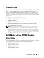 7
7
-
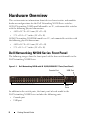 8
8
-
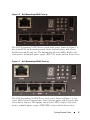 9
9
-
 10
10
-
 11
11
-
 12
12
-
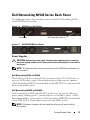 13
13
-
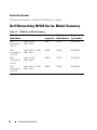 14
14
-
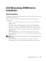 15
15
-
 16
16
-
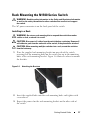 17
17
-
 18
18
-
 19
19
-
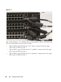 20
20
-
 21
21
-
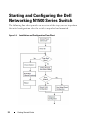 22
22
-
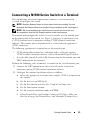 23
23
-
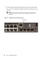 24
24
-
 25
25
-
 26
26
-
 27
27
-
 28
28
-
 29
29
-
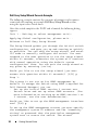 30
30
-
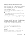 31
31
-
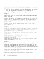 32
32
-
 33
33
-
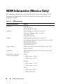 34
34
-
 35
35
-
 36
36
-
 37
37
-
 38
38
-
 39
39
-
 40
40
-
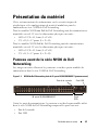 41
41
-
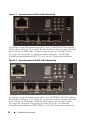 42
42
-
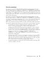 43
43
-
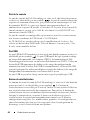 44
44
-
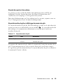 45
45
-
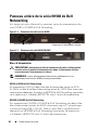 46
46
-
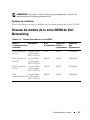 47
47
-
 48
48
-
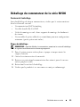 49
49
-
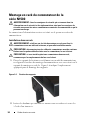 50
50
-
 51
51
-
 52
52
-
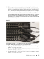 53
53
-
 54
54
-
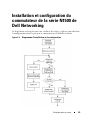 55
55
-
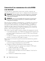 56
56
-
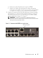 57
57
-
 58
58
-
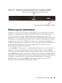 59
59
-
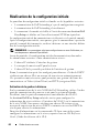 60
60
-
 61
61
-
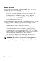 62
62
-
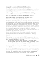 63
63
-
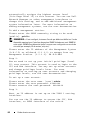 64
64
-
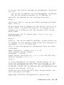 65
65
-
 66
66
-
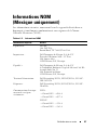 67
67
-
 68
68
-
 69
69
-
 70
70
-
 71
71
-
 72
72
-
 73
73
-
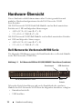 74
74
-
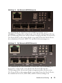 75
75
-
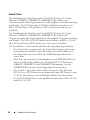 76
76
-
 77
77
-
 78
78
-
 79
79
-
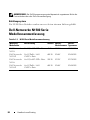 80
80
-
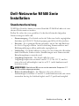 81
81
-
 82
82
-
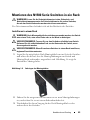 83
83
-
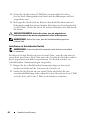 84
84
-
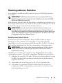 85
85
-
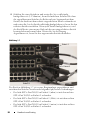 86
86
-
 87
87
-
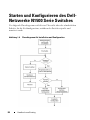 88
88
-
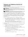 89
89
-
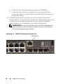 90
90
-
 91
91
-
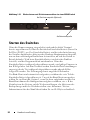 92
92
-
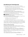 93
93
-
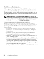 94
94
-
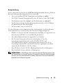 95
95
-
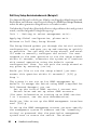 96
96
-
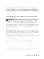 97
97
-
 98
98
-
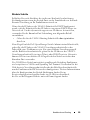 99
99
-
 100
100
-
 101
101
-
 102
102
-
 103
103
-
 104
104
-
 105
105
-
 106
106
-
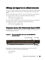 107
107
-
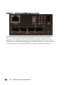 108
108
-
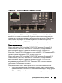 109
109
-
 110
110
-
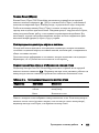 111
111
-
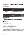 112
112
-
 113
113
-
 114
114
-
 115
115
-
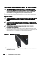 116
116
-
 117
117
-
 118
118
-
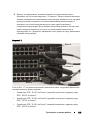 119
119
-
 120
120
-
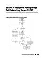 121
121
-
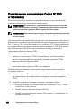 122
122
-
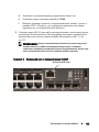 123
123
-
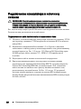 124
124
-
 125
125
-
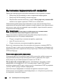 126
126
-
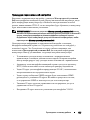 127
127
-
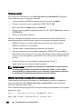 128
128
-
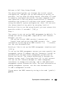 129
129
-
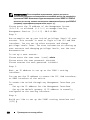 130
130
-
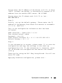 131
131
-
 132
132
-
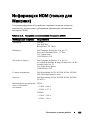 133
133
-
 134
134
-
 135
135
-
 136
136
-
 137
137
-
 138
138
-
 139
139
-
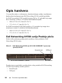 140
140
-
 141
141
-
 142
142
-
 143
143
-
 144
144
-
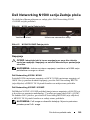 145
145
-
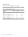 146
146
-
 147
147
-
 148
148
-
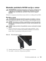 149
149
-
 150
150
-
 151
151
-
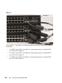 152
152
-
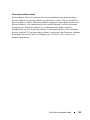 153
153
-
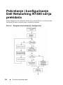 154
154
-
 155
155
-
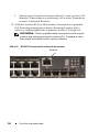 156
156
-
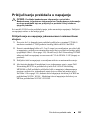 157
157
-
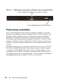 158
158
-
 159
159
-
 160
160
-
 161
161
-
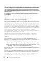 162
162
-
 163
163
-
 164
164
-
 165
165
-
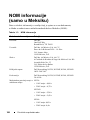 166
166
-
 167
167
-
 168
168
-
 169
169
-
 170
170
-
 171
171
-
 172
172
-
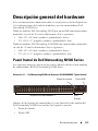 173
173
-
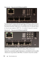 174
174
-
 175
175
-
 176
176
-
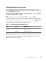 177
177
-
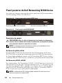 178
178
-
 179
179
-
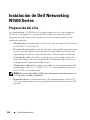 180
180
-
 181
181
-
 182
182
-
 183
183
-
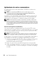 184
184
-
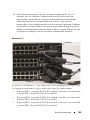 185
185
-
 186
186
-
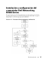 187
187
-
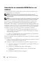 188
188
-
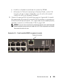 189
189
-
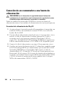 190
190
-
 191
191
-
 192
192
-
 193
193
-
 194
194
-
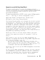 195
195
-
 196
196
-
 197
197
-
 198
198
-
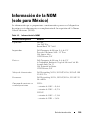 199
199
-
 200
200
-
 201
201
-
 202
202
-
 203
203
-
 204
204
-
 205
205
-
 206
206
-
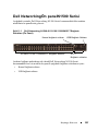 207
207
-
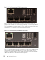 208
208
-
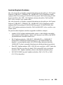 209
209
-
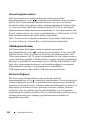 210
210
-
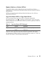 211
211
-
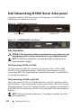 212
212
-
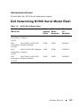 213
213
-
 214
214
-
 215
215
-
 216
216
-
 217
217
-
 218
218
-
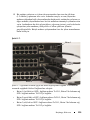 219
219
-
 220
220
-
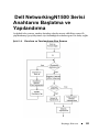 221
221
-
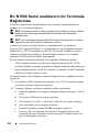 222
222
-
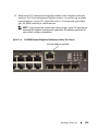 223
223
-
 224
224
-
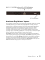 225
225
-
 226
226
-
 227
227
-
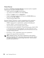 228
228
-
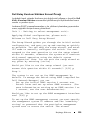 229
229
-
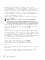 230
230
-
 231
231
-
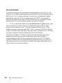 232
232
-
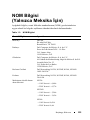 233
233
-
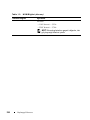 234
234
-
 235
235
-
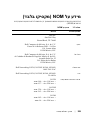 236
236
-
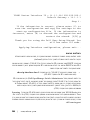 237
237
-
 238
238
-
 239
239
-
 240
240
-
 241
241
-
 242
242
-
 243
243
-
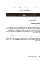 244
244
-
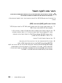 245
245
-
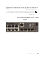 246
246
-
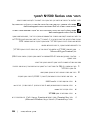 247
247
-
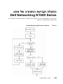 248
248
-
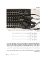 249
249
-
 250
250
-
 251
251
-
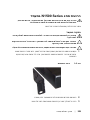 252
252
-
 253
253
-
 254
254
-
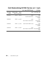 255
255
-
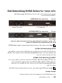 256
256
-
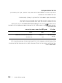 257
257
-
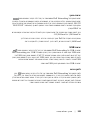 258
258
-
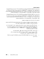 259
259
-
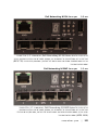 260
260
-
 261
261
-
 262
262
-
 263
263
-
 264
264
-
 265
265
-
 266
266
-
 267
267
-
 268
268


Dell PowerSwitch N1500 Series Guía de inicio rápido
- Categoría
- Conmutadores de red
- Tipo
- Guía de inicio rápido