Sanus Vuepoint F35c Manual de usuario
- Categoría
- Soportes de pared para panel plano
- Tipo
- Manual de usuario

Scan for easy install video
san.us/961
F35c INSTRUCTION MANUAL
We’ll Make It Stress-Free
If you have any questions along the way, just give us a call.
1-888-333-9952. We’re ready to help!

2
Does your TV weigh more than 80 lbs. (36.3 kg) including accessories?
No
—
Perfect!
Yes
—
This mount is NOT compatible. Visit MountFinder.Sanus.com or call 1-888-333-9952 (UK: 0800-056-2853) to fi nd a compatible mount.
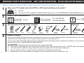
IMPORTANT SAFETY INSTRUCTIONS – SAVE THESE INSTRUCTIONS – PLEASE READ ENTIRE MANUAL PRIOR TO USE
Ready to begin?
Please read through these instructions completely to be sure you’re comfortable with this easy install process. Also check your TV
owner’s manual to see if there are any special requirements for mounting your TV.
If you do not understand these instructions or have doubts about the safety of the installation, assembly or use of this product, contact
Customer Service at 1-888-333-9952 (UK: 0800-056-2853).
Before getting started, let’s make sure this mount is perfect for you!
1
2
3
4
What is your wall made of?
Perfect!
Unsure?
?
Drywall with
wood studs?
Solid concrete or
concrete block?
80 lbs.
(36.3 kg)
Call 1-888-333-9952
(UK: 0800-056-2853)
Call 1-888-333-9952
(UK: 0800-056-2853)
CAUTION: Avoid potential personal injuries and property damage!
● This product is designed for use in wood stud, solid concrete, and concrete block walls - DO NOT install into drywall alone
● The wall must be capable of supporting fi ve times the weight of the TV and mount combined
● Do not use this product for any purpose not explicitly specifi ed by manufacturer
● Manufacturer is not responsible for damage or injury caused by incorrect assembly or use
1/2 in.
(13 mm)
Do you have all of the tools needed? Optional
7/32 in.
(5.5 mm)
Wood
3/8 in.
(10 mm)
Concrete
Stud Finder Awl Pencil Level Phillips
Screwdriver
Tape
Measure
Wood
Drill Bit
Masonry
Drill Bit
Drill HammerSocket

3
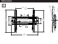
Dimensions
2.04
[51.8]
5º
10º
LEVELING
1.5°
15.75
[400.0]
3.91
[99.4]
15.94
[405.0]
4.75
[120.7]
16.93
[430.0]
6.50
[165.2]
17.78
[451.6]
UP TO
OFFSET
0.38
9.7
in.
[mm]

4
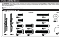
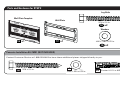
TV Brackets
01 02
Parts and Hardware
WARNING: This product contains small items that could be a choking hazard if swallowed. Before starting assembly, verify all parts
are included and undamaged. If any parts are missing or damaged, do not return the damaged item to your dealer; contact Customer Service.
Never use damaged parts!
Parts and Hardware for STEP 1
NOTE: Not all hardware included will be used.
x1
x1
M4 x 12mm
M4 x 35mm
M5 x 35mm
M6 x 35mm
M8 x 35mm
M5 x 12mm
M6 x 12mm
M8 x 16mm
03
04
05
06
09
x4
x4
x4
x4
x4
TV Screws
10
11
12
x4
x4
x4
Washers
M4/M5 M6/M8
13 14
x4 x4
Spacers
15
x4
M6 x 20mm
M8 x 20mm
07
08
x4
x4

5
Wall Plate Template
Wall Plate
1716
Concrete Installation Kit CMK1 (NOT INCLUDED)
Parts and Hardware for STEP 2
5/16 x 2¾ in.
.695 x .350 x .075 in.
.695 x .350 x.075 in.
5/16 x 2¾ in.
Contact Customer Service at 1-888-333-9952 to have these additional pieces shipped directly to you.
Fischer UX 10 x 60R Anchor
x4
x4
x4
x1
x1
Lag Bolts
Washers
19
x2
5/16 x 2¾ in.
5/16 x 2¾ in.
18
x2
.695 x .350 x.075 in.

6
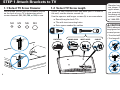
STEP 1 Attach Brackets to TV
M4 M5 M6 M8
FLAT BACK ROUND BACK CABLESINSET HOLES
1-1 Select TV
Screw Diameter
1-2 Select TV
Screw Length
Hand thread screws into the threaded inserts
on the back of your TV to determine which
screw diameter (M4, M5, M6, or M8) to use.
a
b
If your TV has a flat back AND you want your TV closer to
the wall, use the shorter screws (a).
Use the spacers and longer screws (b) to accommodate:
● Round/irregular back TVs
● TVs with inset mounting holes
● Extra space needed for cables
Too Short
Too Long
CAUTION:
Verify adequate thread
engagment with the screw or
screw/spacer combination.
- Too short will not hold the TV.
- Too long will damage the TV.
Correct
Standard configurations
are shown. For special
applications, or if you
are uncertain about your
hardware selection,
contact Customer Service
at 1-888-333-9952.

7
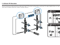
1-3 Attach TV Brackets
Ensure that your brackets are level on the back of the TV. Standard confi gurations are shown. For special applications, or if you are unsure
about your hardware selection, contact Customer Service.
a
Flat Back
b
Round Back / Extra Space
01
02
15
03 04
05
06
13
13
14
14
09
10
11 12
07
08

8
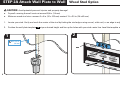
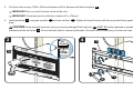
STEP 2A Attach Wall Plate to Wall
Wood Stud Option
CAUTION: Avoid potential personal injuries and property damage!
● Drywall covering the wall must not exceed 5/8 in. (16 mm)
● Minimum wood stud size: common 2 x 4 in. (51 x 102 mm) nominal 1½ x 3½ in. (38 x 89 mm)
1. Locate your stud. Verify and mark the center of the stud by finding the stud edges using an awl, a thin nail, or an edge to edge stud finder.
2. Position the wall plate template
16
at your desired height and line up the holes with your stud center line. Level the template and tape in place.
2
1
Max. 5/8 in.
(16 mm)
16

9
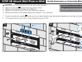
3. Drill pilot holes using a 7/32 in. (5.5 mm) diameter drill bit. Remove wall plate template
16
.
IMPORTANT: Be sure to drill into the center of the stud.
IMPORTANT: Pilot holes must be drilled to a depth of 3 in. (75 mm).
4. Install wall plate
17
using two lag bolts
18
and two washers
19
. Tighten the lag bolts only until they are pulled firmly against the wall
plate.
CAUTION: Avoid potential personal injury or property damage! Both lag bolts
18
MUST BE firmly tightened to prevent unwanted
movement of the wall plate
18
.
Ensure the wall plate is securely fastened to the wall before continuing on to the next step.
4
18
19
3
3 in.
(75 mm)
17
16
7/32 in.
(5.5 mm)

10
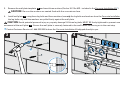
STEP 2B Attach Wall Plate to Wall
Solid Concrete or Concrete Block Option
2
1
Concrete Installation Kit CMK1 is not included
(see page 5) Contact Customer Service
at 1-888-333-9952 to have the additional
hardware shipped directly to you.
3/8 in.
(10 mm)
3 in.
(75 mm)
Min.
4 ¾ in.
(120.6 mm)
CAUTION: Avoid potential personal injuries and property damage!
● Mount the wall plate
17
directly onto the concrete surface
● Minimum solid concrete thickness: 8 in. (203 mm)
● Minimum concrete block size: 8 x 8 x 16 in. (203 x 203 x 406 mm)
● Minimum horizontal space between the top two fasteners: 4 ¾ in. (120.6 mm)
1. Position the wall plate template
16
on the wall at your desired height. Level the wall plate template and mark the hole locations.
2. Drill three pilot holes using a 3/8 in. (10 mm) diameter masonry drill bit.
16
16

11
43
17
*
*
3. Remove the wall plate template
16
and insert three anchors (Fischer UX 10 x 60R - included in the Concrete Installation Kit*).
CAUTION: Be sure the anchors are seated flush with the concrete surface.
4. Install wall plate
17
using three lag bolts and three washers (use only the lag bolts and washers from the Concrete Installation Kit*). Tighten
the lag bolts only until the washers are pulled firmly against the wall plate.
CAUTION: Avoid potential personal injury or property damage! All three lag bolts MUST BE firmly tightened to prevent unwanted
movement of the wall plate
17
.
Ensure the wall plate is securely fastened to the wall before continuing on to the next step.
*
Contact Customer Service at 1-888-333-9952 to have the Concrete Installation Kit shipped directly to you.

12
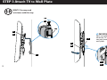
STEP 3 Attach TV to Wall Plate
HEAVY! You may need
assistance with this step.
IMPORTANT: You will
hear an audible click
when the TV bracket is
securely fastened to the
wall plate.
17
02
01
17
01
02
17
01
02
02
01
17

13
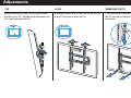
Adjustments
Loosen the knob on the TV bracket to adjust
the tilt of your TV. Tighten the knob when your
TV is set to the desired tilt.
Pull down on the latches and lift
the TV up and out away from the
wall plate.
TILT
LEVEL
If needed, tighten one of the screws on the top
of the TV bracket to level the TV.
TILT REMOVING THE TVLEVEL

14
ESPAÑOL
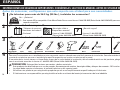
INSTRUCCIONES DE SEGURIDAD IMPORTANTES. CONSÉRVELAS. LEA TODO EL MANUAL ANTES DE UTILIZAR ESTE PRODUCTO.
¿Su televisor pesa más de 36.3 kg (80 lbs.), incluidos los accesorios?
No
—
¡Perfecto!
Sí
—
Este soporte NO es compatible. Visite MountFinder.Sanus.com o llame al 1-888-333-9952 (Reino Unido: 0800-056-2853) para encontrar un
soporte compatible.
Antes de comenzar, verifiquemos que este soporte sea el ideal para sus necesidades.
1
2
3
4
¿De qué está hecha su pared?
¡Perfecto! Llame al 1-888-333-9952
(Reino Unido: 0800-056-2853)
Llame al 1-888-333-9952
(Reino Unido: 0800-056-2853)
¿No está seguro?
?
¿Tabiques de yeso con
montantes de madera?
¿Hormigón sólido o
bloques de cemento?
36.3 kg
(80 lbs.)
¿Listo para comenzar?
Lea estas instrucciones en su totalidad para estar seguro de sentirse cómodo con este fácil proceso de instalación. Consulte también el manual del
usuario de su televisor para ver si existe algún requisito especial para instalar su televisor en la pared.
Si no entiende las instrucciones o si tiene dudas acerca de la seguridad de la instalación, del ensamblado o del uso del producto, póngase en contacto
con el servicio de atención al cliente al 1-888-333-9952 (Reino Unido: 0800-056-2853).
PRECAUCIÓN: Evite posibles lesiones personales y daños materiales.
• Este producto fue diseñado para su uso en paredes de montantes de madera, hormigón sólido y bloques de cemento
- NO instalar en yeso solo
• La pared debe soportar cinco veces el peso del televisor y del soporte juntos
• No utilice este producto para ningún otro propósito que no sea el explícitamente especificado por el fabricante
• El fabricante no se responsabiliza por ningún daño o lesión resultante del montaje incorrecto o del uso indebido
¿Tiene todas las herramientas necesarias?
10 mm
(3/8'')
Hormigón
Opcional
Herramienta
de nivelaciónLápiz
Localizador
de montantes Destornillador
Cinta métrica
5.5 mm
(7/32")
Madera
Broca BrocaMartillo
Taladro eléctrico
13 mm
(1/2")
Llave de tubo
Lezna

15
ESPAÑOL
NOTA: No todos los elementos de sujeción incluidos deberán utilizarse.
ADVERTENCIA: Este producto contiene piezas pequeñas que, si fuesen tragadas, podrían producir asfixia.
Antes de iniciar el ensamblaje, compruebe que todas las piezas estén incluidas y en buenas condiciones. Si faltan piezas o alguna está dañada,
no devuelva el artículo al distribuidor; póngase en contacto con el servicio de atención al cliente. Nunca utilice piezas deterioradas.
Asegúrese de que las placas de sujeción
01
02
queden niveladas en la parte posterior del televisor. Si necesita más espacio para cables,
concavidades o protuberancias, use los espaciadores (consulte la opción para dorso irregular en la siguiente página).
IMPORTANTE: Luego de fijar las placas de sujeción, ajuste las correas para nivelarlas con la parte inferior del televisor.
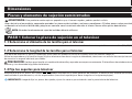
Piezas y elementos de sujeción suministrados
PASO 1 Colocar la placa de sujeción en el televisor
Dimensiones
Ver página 3
Ver página 4
Ver página 6
1-1 Seleccione el diámetro
de los tornillos para el televisor
1-2 Seleccione la longitud
de los tornillos para el televisor
1-3 Fije los soportes para televisor
Enrosque manualmente los tornillos en los encastres roscados del dorso del televisor a fin de determinar qué diámetro de tornillos (M4, M5, M6 o M8) utilizar.
PRECAUCIÓN: Verifique que el tornillo o la combinación de tornillo y separador enrosquen correctamente. Si el tornillo es demasiado corto no sostendrá el
televisor y, si es demasiado largo, dañará el televisor.
Si el dorso del televisor es plano Y usted desea que el televisor quede más cerca de la pared, utilice los tornillos cortos (a).
Utilice los separadores y los tornillos largos (b) para: televisores con dorso irregular o redondeado, televisores con orificios de montaje intercalados o en el caso
de necesitar un espacio adicional para cables.

16
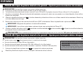
ESPAÑOL
PRECAUCIÓN: Evite posibles lesiones personales y daños materiales.
● El yeso que recubre la pared no debe exceder los 16 mm (5/8 pulgada).
● Tamaño mínimo del montante de madera: común 51 mm x 102 mm (2 x 4 pulgadas) (nominal 38 mm x 89 mm [1½ x 3½ pulgadas])
1. Localice un montante. Busque los bordes del montante y marque el centro con un punzón o un clavo delgado, o bien utilice un detector de
bordes de montantes.
2. Ubique la plantilla de placa mural
16
a la altura deseada y alinee los orificios con la línea central de los montantes. Nivele la plantilla y fíjela
con cinta adhesiva en el lugar.
3. Realice los orificios guía con una mecha de 5,5 mm (7/32”) de diámetro. Retire la plantilla de la placa mural
16
.
IMPORTANTE: Asegúrese de perforar el centro del montante.
IMPORTANTE: Los orificios guía deben realizarse hasta una profundidad de 75 mm (3’’).
4. Instale el módulo de la placa mural
17
usando dos tornillos tirafondo
18
y dos arandelas
19
. Ajuste los tornillos tirafondo solamente hasta
que queden firmes contra la placa mural.
PRECAUCIÓN: El uso indebido podría reducir la capacidad de retención de los tornillos. NO ajuste en exceso los tornillos tirafondo.
PRECAUCIÓN: Evite posibles lesiones personales y daños materiales.
● Instale la placa mural
17
directamente sobre la superficie de hormigón.
● Espesor mínimo del hormigón: 203 mm (8 pulgadas)
● Tamaño mínimo del bloque de cemento: 203 x 203 x 406 mm (8 x 8 x 16 pulgadas)
● Espacio horizontal mínimo entre los dos sujetadores superiores: 120,6 mm (4 3/4 pulgadas)
1. Coloque la plantilla de la placa mural
16
en la pared a la altura que desee.
Nivele la plantilla de la placa mural y marque la ubicación de los orificios.
PASO 2A Fijar la placa mural a la pared - Opción para montantes de madera
PASO 2B Fijar la placa mural a la pared -
Opción para hormigón sólido o bloques de cemento
Ver página 8
Ver página 10
El Kit de instalación en hormigón CMK1 no
está incluido (Ver página 5) Comuníquese
con el servicio de atención al cliente al
1-888-333-9952 para solicitar que le enviemos
los elementos de sujeción adicionales.

17
ESPAÑOL
¡ELEMENTO PESADO! Es posible que necesite ayuda
en este paso.
IMPORTANTE: Oirá un clic cuando la placa de sujeción del
televisor esté bien sujeta a la placa mural.
PASO 3 Instalar el televisor en la pared
Ajustes
Ver página 12
Ver página 13
AJUSTE DE LA INCLINACIÓN: Afloje la perilla
que se encuentra en la placa de sujeción del
televisor a fin de ajustar la inclinación de su
televisor. Ajuste la perilla cuando su televisor
tenga la inclinación deseada.
RETIRAR EL TELEVISOR: Jale hacia
abajo de las correas, levante el
televisor y retírelo de la placa mural.
AJUSTE DE LA NIVELACIÓN: Si es necesario,
ajuste uno de los tornillos de la parte superior
de la placa de sujeción del televisor para nivelar
el televisor.
2. Realice los orificios guía con una mecha para mampostería de 10 mm (3/8’’) de diámetro.
IMPORTANTE: Los orificios guía deben realizarse hasta una profundidad de 75 mm (3’’). Nunca perfore el cemento que une los bloques.
3. Retire la plantilla de la placa mural
16
e introduzca tres anclajes (Fischer UX 10 x 60R - incluidos en el Kit de instalación en hormigón CMK1*).
PRECAUCIÓN: Cerciórese de que los anclajes queden nivelados respecto de la superficie de hormigón.
4. Instale el módulo de la placa mural
17
usando tres tornillos tirafondo y tres arandelas (utilizar únicamente los tornillos tirafondo y las
arandelas del Kit de instalación en hormigón CMK1*). Ajuste los tornillos tirafondo solamente hasta que queden firmes contra la placa mural.
PRECAUCIÓN: El uso indebido podría reducir la capacidad de retención de los tornillos. NO ajuste en exceso los tornillos tirafondo.
*
Comuníquese con el servicio de atención al cliente al 1-888-333-9952 para solicitar que le enviemos el Kit de instalación en hormigón.

18

19

SANUS • 6436 City West Parkway • Eden Prairie, MN 55344 USA 6902-002095 01
Milestone AV Technologies and its a liated corporations and subsidiaries (collectively, “Milestone”), intend to make this manual accurate and complete. However,
Milestone makes no claim that the information contained herein covers all details, conditions, or variations. Nor does it provide for every possible contingency in
connection with the installation or use of this product. The information contained in this document is subject to change without notice or obligation of any kind.
Milestone makes no representation of warranty, expressed or implied, regarding the information contained herein. Milestone assumes no responsibility for accuracy,
completeness or su ciency of the information contained in this document.
©2015 Milestone AV Technologies. All rights reserved. Sanus is a division of Milestone.
All other brand names or marks are used for identifi cation purposes and are trademarks of their respective owners.
Thank you for choosing Sanus VuePoint! Please take a moment to let us know how we did:
Call us: 1-888-333-9952
UK: 0800 056 2853
Email us: [email protected] Leave a review: vuepoint.sanus.com
Find us on Facebook: SANUS Follow us on Twitter @sanussystems
-
 1
1
-
 2
2
-
 3
3
-
 4
4
-
 5
5
-
 6
6
-
 7
7
-
 8
8
-
 9
9
-
 10
10
-
 11
11
-
 12
12
-
 13
13
-
 14
14
-
 15
15
-
 16
16
-
 17
17
-
 18
18
-
 19
19
-
 20
20


Sanus Vuepoint F35c Manual de usuario
- Categoría
- Soportes de pared para panel plano
- Tipo
- Manual de usuario
en otros idiomas
- English: Sanus Vuepoint F35c User manual
Artículos relacionados
-
Sanus DLT1 Manual de usuario
-
-
-
-
-
-
-
Sanus MLF13-B1 Manual de usuario
-
-