
T9 SMART THERMOSTAT
RCHT9510WFW2003
Installation Guide
Online Guides
Resideo.com

2
M38354
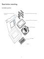
Read before installing.
Included in your box:
Thermostat
Literature
Screws and anchors
T9 Smart Thermostat
UWP Wallplate
Wire labels

3
Tools you will need: You may need:
Phillips screwdriver Wire Stripper
Home WiFi Password
Small flat head screwdriver
Needle-nose pliers
Pencil
Drill and drill bit
Level
Flashlight

4
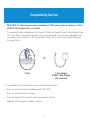
Compatibility Section
• REQUIRED: A CWire (common wire) is needed for 24 VAC power. If you do not have a CWire,
a FREE CWire Adapter offer is included.
This guide will help you determine if you have a CWire or will need to use a CWire Adapter (Step
10). The CWire is a wire that originates from your heating and cooling system and needs to be
connected to the C terminal on your thermostat. There is no universal color used to designate
this type of wire.
• Compatible with most heating/cooling, and heat pump systems
• Does not work with electric baseboard heat (120240V)
• Does not work with millivolt systems
• Does not support S terminals for indoor and outdoor sensors
• Android or iOS smartphone, tablet, or device
C
CU
GY
GY
A
OR
CWire CWire Adapter
(FREE CWire Adapter
offer included)

5
For help, see:
ONLINE GUIDES AND SUPPORT VIDEOS AT: Resideo.com
SOCIAL Twitter: @Honeywell_Home, Facebook: Honeywell Home
Or contact:
PHONE 18006333991
CAUTION: ELECTRICAL HAZARD
Can cause electrical shock or equipment damage. Disconnect power before beginning installation.
CAUTION: EQUIPMENT DAMAGE HAZARD
Compressor protection is bypassed during testing. To prevent equipment damage, avoid cycling the compressor quickly.
CAUTION: MERCURY NOTICE
If this product is replacing a control that contains mercury in a sealed tube, do not place the old control in the trash. Contact
your local waste management authority for instructions regarding recycling and proper disposal.

6
Removing your old thermostat
You will need: Screwdriver, needle-nose pliers
OFF
ON
75
1
2
3
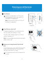
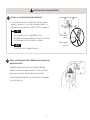
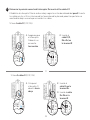
Turn off power
To protect your equipment, turn off the power
at the breaker box or switch that controls you
heating and cooling equipment.
Note: The thermostat off switch will not turn off
the power to the equipment.
Check that your system is off
Change the temperature on your old thermostat so
that your system starts heating or cooling.
If you don’t hear or feel the system turn on within 5
minutes, the power is off.
Note: If you have a digital thermostat that has a blank
display, skip this step.
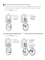
Remove your existing thermostat from the wall
plate
On most thermostats, you can take off the thermostat
by grasping and gently pulling. Some thermostats
may have screws, buttons, or clasps.
Do not remove any wires from your thermostat at
this time!
OR
OFF
Breaker box
Switch

7
5
4
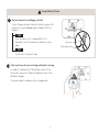
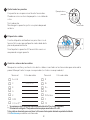
Take a picture of your existing wall plate’s wiring
In order to capture all of the letters next to the
terminals, be sure to take multiple pictures from
different angles.
You may need to reference this image later.
Do you have a line voltage system?
Line voltage systems have thick black wires with
wire nuts or are labeled high voltage (120V or
higher).
Your system is not compatible. Go to
Resideo.com to find a pro installer in your
area.
Continue to the next step.
Wire nut
Thick black wire
Compatibility Check
YES
NO

8
6
7
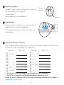
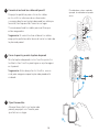
Remove any jumpers
A jumper is used to connect two terminals. It may look
like a small staple or a colored wire.
Do not discard.
Keep jumpers with your old wallplate.
Label the wires
Use the stickers provided with your new thermostat to
label each wire on your existing wall plate.
Do not label jumpers. Your new thermostat does not
need jumpers.
Example
of a jumper
Terminals
YRRC
8Write down the colors of the wires
Check the boxes and write down the color of the wires connected to terminals that are coming
from the wall. Check all that apply (not all will apply).
Terminal Wire Color Terminal Wire Color
¨A or L/A ¨R
¨CRequired* ¨Rc
¨E¨Rh
¨G¨W
¨K¨W2 or Aux
¨O/B ¨Y
¨U (1 or 2)** ¨Y2
* A C-wire or CWire Power Adapter (see included free offer) is required.
** The T9 Smart thermostat cannot control equipment wired to U1 or U2.
If there are wires in terminals that are not listed, you will need additional wiring support. Visit
Resideo.com to find out more.

9
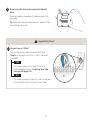
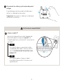
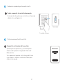
10 Do you have a CWire?
Look at the thermostat wiring checklist from
Step 8, or the photo you took. Is the CTerminal
checked?
This means you will not need to install a
CWire Adapter. Skip to Installing Your New
Thermostat (page 13).
This means you don’t have a C-wire connected
to your thermostat. Continue to next step.
Compatibility Check
YES
NO
9Disconnect the wires and remove the old wall
plate
You may need a screwdriver to release wires from
terminals.
Tip: Wrap the wires around a pencil to prevent them
from falling in the wall.
C
CU
GY
GY
A

10
11
12
Do you have a zoning panel?
You have a zoning panel if you have multiple
thermostats and one furnace or heating system.
CWire Adapter installation is more complicated
on zoned systems. Go to Resideo.com to find a
pro installer in your area.
Proceed to the next step.
Do you have an unused wire?
Look at the bundle of wires coming from the wall.
Note: You may have to pull the bundle of wires out
from the wall to find the unused wire.
Continue to Step 13.
See the CWire Power Adapter FREE OFFER
included in the thermostat box. Follow the
instructions that come with the CWire Power
Adapter, and then return to page 13 of this
guide to complete the installation.
Compatibility Check
YES
YES
NO
NO
Only complete this section if you answered No to Step 10
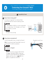
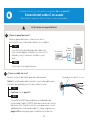
Connecting Your Unused CWire
You will need: Screwdriver, flashlight, wire strippers
Thermostat
Furnace
Example of unused C-wire
Zoning
Panel

11
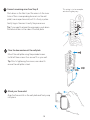
13 Label unused wire
Label your unused wire with the
provided “C” sticker label. You may need
to use a wire stripper to expose at least
1/4 inch of the wire.
Note: If you have multiple unused wires,
then label only one wire and make note
of the color here:
-
Go to your furnace or heating system
This system is often located in your basement, attic or garage.
Bring a flashlight and screwdriver.
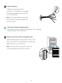
14 Remove cover from furnace or heating system
Open the heating and cooling system’s cover to find
the control board. You should see the same terminal
labels that are on your thermostat.
Note: You may need to unscrew the cover. The
control board may be at the top or bottom.
G
C
R
W
Y

12
16
15
17
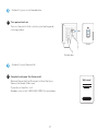
Connect the unused wire to the C-terminal
Note: If there are existing wires in the C-terminal,
make sure they are still connected to the C-terminal
after connecting this wire.
Find the other end of the unused wire
Locate the bundle of wires that are the same as the
ones at your thermostat.
The unused wire should be the same color as the one
near your existing thermostat. See Step 13 for the
color you wrote down.
Close the cover to the furnace or heating system
Be sure the cover is completely closed. Some systems
will not power up if the cover isn’t fully closed.
You’ve connected the C-wire.
You will NOT need to use a CWire Adapter.
G
C
R
W
Y
G
C
R
W
Y
-
Go back to the wall where you are installing your thermostat and continue to “Installing Your
New Thermostat” on the next page.

13
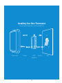
Installing Your New Thermostat
You will need: Level, pencil, drill and a drill bit
Thermostat Screws UWP
wallplate
WallAnchors

14
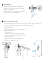
18
19
Position wall plate
Pull open the wall plate that was included with your
new thermostat. Insert the bundle of wires through
the back of the wall plate.
Make sure at least 1/4-inch of each wire is exposed
for easy insertion into the wire terminals.
Insert recommended wall anchors
It is recommended that you use the wall anchors included in the box to mount your thermostat.
You can use the wall plate to mark where you want to place the wall anchors.
a) Level the wall plate
b) Mark the location of the wall anchors using a pencil
c) Remove the wall plate
d) Drill anchor holes.
If your box contains red anchors, drill 7/32” holes.
If your box contains yellow anchors, drill 3/16” holes.
e) Insert the wall anchors
f) Make sure the anchors are flush with the wall
g) Reposition the wall plate on wall
-
UWP
Anchors Wall

15
1. Ensure the
right R-switch
is in the up
position.
1. Set right
R-switch to the
down position.
UWP
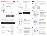
20 Determine Correct RSwitch Position and Insert R-wire or wires
Set the R-switch up or down based on your wiring notes in Step 8. Insert wires into the inner
holes of the terminals on the wall plate. The tabs will stay down once the wire is inserted.
If you have 1 RWire (R, RC, RH):
If you have 2 RWires (R, RC, RH):
2. Insert your
R-wire (R, Rh
or Rc) into
R-terminal.
2. Insert your Rc
wire into Rc-
terminal.
3. Insert your R
or Rh wire into
R-terminal.
OR

16
22
23
Close the door and mount the wall plate
Mount the wall plate using the provided screws.
Install all three screws for a secure fit on your wall.
Tip: Prior to tightening the screws, use a level to
ensure the wall plate is level.
Attach your thermostat
Align the thermostat on the wall plate and firmly snap
into place.
21 Connect remaining wires from Step 8
Push down on the tabs to put the wires into the inner
holes of their corresponding terminals on the wall
plate (one wire per terminal) until it is firmly in place.
Gently tug on the wires to verify they are secure.
Tip: If you need to release the wires again, push down
the terminal tabs on the sides of the wall plate.
This wiring is just an example,
actual wiring may vary.

17
24
25
Turn power back on
Turn on the switch that controls your heating and
cooling system.
Complete setup on the thermostat
Remove the protective film and confirm that your
thermostat reads “Welcome.”
If you do not see this, visit
Resideo.com or call 18006333991 for more help.
Go back to your circuit breaker box.
Go back to your thermostat.
OFF
ON
ON
Breaker box
Switch
Welcome!

18
Getting the most from the T9 Smart Thermostat
Prioritize Rooms (Requires optional Wireless Room Sensor accessory)
Prioritize a specific room or multiple rooms, or let comfort follow your move using built-in motion
detection.
Control on the Go
Adjust your thermostat from anywhere using your tablet or smartphone.
Save Energy
With geofencing, you can save money on the most expensive part of your energy bill while you’re
away.
Simple Installation
The thermostat automatically programs itself. Just answer a few simple questions and you’ll be up
and running in no time.
WholeHome Range (Requires optional Wireless Room Sensor accessory)
With up to a 200-foot* range, 20 sensors with temperature, humidity, and occupancy detection can
connect to your thermostat from throughout your home.
*Range can vary based on home construction, wireless interference, and other factors.
Know Your Home Is Safe
Get customizable alerts on your mobile device such as when the basement is so cold a pipe could
burst, or if the baby’s room is getting too hot.

19
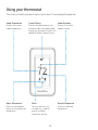
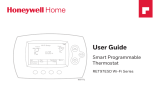
Using your thermostat
The screen will wake up by pressing the center area of the displayed temperature.
74
2
18%
Indoor Temperature
Displays the current
indoor temperature.
Adjust Temperature
Touch the up and down
arrows to set your desired
temperature.
Current Priority
Displays the type of priority and
number of rooms being prioritized.
Extend your thermostat’s reach with
additional Wireless Room Sensors.
Menu
Contains features such
as mode, fan, schedule,
priority, and other
thermostat settings.
Indoor Humidity
Displays the current
indoor humidity.
Desired Temperature
Displays the desired
temperature.

20
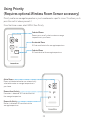
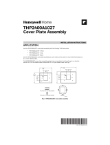
Using Priority
(Requires optional Wireless Room Sensor accessory)
Priority creates an average temperature in your home based on specific rooms. This allows you to
prioritize comfort where you want it.
From the Home screen, select MENU, then Priority.
Selected Rooms
Rooms you manually select create an average
temperature in your home.
Unselected Room
Will not contribute to the average temperature.
Selected Room
Will contribute to the average temperature.
72 72
72 72
72 72
72 72
Active Rooms
Rooms with detected motion are automatically
selected to create an average temperature in
your home.
Room without Activity
No motion is detected. Will not contribute to
the average temperature.
Room with Activity
Motion is detected. Will contribute to the
average temperature.

21
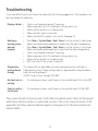
Troubleshooting
If you have difficulty with your thermostat, please try the following suggestions. Most problems can
be corrected quickly and easily.
Display is blank • Check circuit breaker and reset if necessary.
• Make sure power switch for heating & cooling system is on.
• Make sure furnace door is closed securely.
• Make sure the C wire is connected.
• Make sure the R/Rc jumper is set correctly. See page 15.
Heating or
cooling system
does not
respond
• Press Menu > System Mode > Heat > Done to set the system to Heat mode.
Make sure the desired temperature is higher than the indoor temperature.
• Press Menu > System Mode > Cool > Done to set the system to Cool mode.
Make sure the desired temperature is lower than the indoor temperature.
• Check circuit breaker and reset if necessary.
• Make sure power switch for heating & cooling system is on.
• Make sure furnace door is closed securely.
• Wait 5 minutes for the system to respond.
Temperature
settings do not
change
This thermostat has adjustable minimum and maximum limit settings for
heating and cooling. If these settings were not adjusted when setup was done,
heat has a setting range of
4090°F and cool has a range of 5099°F.
Aux heat runs in
cooling
• For heat pump systems, verify there is not a wire attached to W on the UWP.
Cool runs with a
call for heat
• For heat pump systems, verify there is not a wire attached to W the UWP.
The product should not be disposed of with other household waste. Check for the nearest
authorized collection centers or authorized recyclers. The correct disposal of end-of-life
equipment will help prevent potential negative consequences for the environment and
human health.

22
Resideo warrants this product to be free from defects in workmanship or materials, under normal use and service, for a period of two
(2) years from the date of first purchase by the original purchaser. If at any time during the warranty period the product is determined
to be defective due to workmanship or materials, Resideo shall repair or replace it (at Resideo’s option).
If the product is defective,
(i) return it, with a bill of sale or other dated proof of purchase, to the place from which you purchased it; or
(ii) call Resideo Customer Care at 18006333991. Customer Care will make the determination whether the product should be
returned to the following address: Resideo Return Goods, Dock 4 MN103860, 1885 Douglas Dr. N., Golden Valley, MN 55422, or
whether a replacement product can be sent to you.
This warranty does not cover removal or reinstallation costs. This warranty shall not apply if it is shown by Resideo that the defect was
caused by damage which occurred while the product was in the possession of a consumer.
Resideo’s sole responsibility shall be to repair or replace the product within the terms stated above. RESIDEO SHALL NOT BE LIABLE
FOR ANY LOSS OR DAMAGE OF ANY KIND, INCLUDING ANY INCIDENTAL OR CONSEQUENTIAL DAMAGES RESULTING, DIRECTLY
OR INDIRECTLY, FROM ANY BREACH OF ANY WARRANTY, EXPRESS OR IMPLIED, OR ANY OTHER FAILURE OF THIS PRODUCT.
Some states do not allow the exclusion or limitation of incidental or consequential damages, so this limitation may not apply to you.
THIS WARRANTY IS THE ONLY EXPRESS WARRANTY RESIDEO MAKES ON THIS PRODUCT. THE DURATION OF ANY IMPLIED
WARRANTIES, INCLUDING THE WARRANTIES OF MERCHANTABILITY AND FITNESS FOR A PARTICULAR PURPOSE, IS HEREBY
LIMITED TO THE TWO YEAR DURATION OF THIS WARRANTY. Some states do not allow limitations on how long an implied warranty
lasts, so the above limitation may not apply to you.
This warranty gives you specific legal rights, and you may have other rights which vary from state to state. If you have any questions
concerning this warranty, please write Resideo Customer Care, 1985 Douglas Dr, Golden Valley, MN 55422 or call 18006333991.
2-year limited warranty
The operation of this equipment is subject to the following two conditions: (1) this equipment or device may not cause harmful
interference, and (2) this equipment or device must accept any interference, including interference that may cause undesired
operation.

23
Electrical Ratings
INPUT: 24V~@60Hz, 0.2A
Terminal Voltage
(50/60Hz)
Running
Current
W Heating 2030 Vac 0.021.0 A
W2 (Aux) Heating 2030 Vac 0.021.0 A
E Emergency Heat 2030 Vac 0.020.5 A
Y Compressor Stage 1 2030 Vac 0.021.0 A
Y2 Compressor Stage 2 2030 Vac 0.021.0 A
G Fan 2030 Vac 0.020.5 A
O/B Changeover 2030 Vac 0.020.5 A
L/A Input 2030 Vac 0.020.5 A
NOTE: Not for use with 250, 500, or 750 MV systems.

Apple® HomeKit™ Setup Code
The T9 Pro Smart supports Apple HomeKit. When prompted by the Honeywell Home app, scan the
code on the back cover of the guide included with your T9 Smart thermostat.
Resideo Technologies Inc.
1985 Douglas Drive North, Golden Valley, MN 55422
1-800-633-3991
33-00525ES—01 M.S. Rev. 03-20 | Printed in United States
www.resideo.com
© 2020 Resideo Technologies, Inc. All rights reserved.
The Honeywell Home trademark is used under license from Honeywell International, Inc.
This product is manufactured by Resideo Technologies, Inc. and its affiliates.
Todos los derechos reservados. La marca comercial Honeywell Home se utiliza bajo licencia
de Honeywell International, Inc.
Este producto es fabricado por Resideo Technologies, Inc. y sus afiliados.
33-00525ES-01

Guías en línea
Resideo.com
TERMOSTATO INTELIGENTE T9
RCHT9510WFW2003
Guía de instalación

2
M38354
Leer antes de instalar.
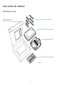
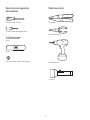
Contenido de la caja:
Material de lectura
sobre el termostato
Tornillos y anclajes
T9 Smart Thermostat
Placa de pared UWP
Etiquetas de cableado

3
Necesitará las siguientes
herramientas:
Podría necesitar:
Destornillador Phillips Pelacables
Contraseña de la red wifi del hogar
Destornillador plano pequeño
Alicates de punta
Lápiz
Taladro y broca
Nivel
Linterna

4
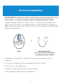
Sección de compatibilidad
• REQUERIMIENTOS: Se requiere un cable C (común) para una alimentación de 24 V CA. Si no
tiene un cable C, se incluye una oferta para obtener un adaptador del cable C GRATIS.
Esta guía lo ayudará a determinar si tiene un cable C o si necesitará usar un adaptador del
cable C (paso 10). El cable C es un cable que sale de su sistema de calefacción y refrigeración y
debe conectarse a la terminal C del termostato. No hay un color que se use universalmente para
designar este tipo de cable.
• Compatible con la mayoría de los sistemas con bombas de calor/de calefacción y de
refrigeración.
• No funciona con calefactores eléctricos de base portátil (de 120 V a 240 V).
• No funciona con sistemas de milivoltio.
• No admite terminales S para sensores interiores y exteriores.
• Teléfono inteligente, tableta o dispositivo Android o iOS
C
CU
GY
GY
A
O
Cable C Adaptador del cable C
(Se incluye una oferta para obtener
un adaptador del cable C GRATIS)

5
PRECAUCIÓN: PELIGRO ELÉCTRICO
Puede causar una descarga eléctrica o daños al equipo. Desconecte la corriente antes de comenzar la instalación.
PRECAUCIÓN: PELIGRO DE DAÑOS AL EQUIPO
La protección del compresor se omite durante la prueba. Para evitar daños al equipo, evite alternar el compresor
rápidamente.
PRECAUCIÓN: AVISO SOBRE EL MERCURIO
El producto no debe desecharse junto con otros residuos domésticos si reemplaza un control que contiene mercurio.
Comuníquese con la autoridad local de gestión de residuos para obtener instrucciones sobre cómo desecharlo y reciclarlo
de forma apropiada.
Para obtener ayuda, consulte lo siguiente:
GUÍAS Y VIDEOS DE SOPORTE EN LÍNEA EN: Resideo.com
REDES SOCIALES Twitter: @Honeywell_Home, Facebook: Honeywell Home
O póngase en contacto:
CORREO ELECTRÓNICO Honeywellhomesuppor[email protected]
TELÉFONO 18006333991

6
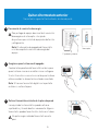
Quitar el termostato anterior
Necesitará lo siguiente: Destornillador, alicates de punta
OFF
ON
75
1
2
3
Desconecte el suministro de energía
Para proteger el equipo, desconecte el suministro
de energía en el interruptor o la caja de
disyuntores que controla el equipo de calefacción
y refrigeración.
Nota: El interruptor de apagado del termostato
no interrumpirá el suministro de energía del
equipo.
Asegúrese que el sistema esté apagado
Cambie la temperatura del termostato anterior para
que el sistema comience a calefaccionar o refrigerar.
Si a los 5 minutos no escucha o siente que el sistema
está encendido, la alimentación está desconectada.
Nota: Si tiene un termostato digital con la pantalla
en blanco, omita este paso.
Retire el termostato existente de la placa de pared
La mayoría de los termostatos pueden retirarse
sujetándolos y tirando de ellos suavemente. Algunos
termostatos pueden tener tornillos, botones o trabas.
No quite ningún cable del termostato en este
paso.
O
OFF
Caja de disyuntores
Interruptor

7
5
4
Tome una fotografía del cableado de su placa de
pared existente
Asegúrese de tomar varias fotografías desde
ángulos diferentes para capturar todas las letras
que se encuentran al lado de las terminales.
Es posible que después necesite tomar la imagen
como referencia.
¿Tiene un sistema de tensión de línea?
Los sistemas de tensión de línea tienen cables
negros y gruesos con conectores de cable o se
etiquetan como de alto voltaje (120 V o superior).
Su sistema no es compatible. Visite
Resideo.com para obtener información sobre
un instalador profesional en su área.
Continúe con el siguiente paso.
Conector de
cables
Cable negro y
grueso
Verificación de compatibilidad
SÍ
NO

8
6
7
Quite todos los puentes
Un puente se usa para conectar dos terminales.
Puede ser como un broche pequeño o un cable de
color.
No lo deseche.
Mantenga los puentes junto a su placa de pared
anterior.
Etiquete los cables
Use las etiquetas autoadhesivas provistas con el
termostato nuevo para etiquetar cada cable de la
placa de pared existente.
No etiquete los puentes. El termostato nuevo no
requiere de ningún puente.
Ejemplo de un
puente
Terminales
YRRC
8Anote los colores de los cables
Marque las casillas y anote el color de los cables conectados a las terminales que salen de la
pared. Marque todos los que correspondan (no todos corresponderán).
Terminal Color de cable Terminal Color de cable
¨A o L/A ¨R
¨CRequerido* ¨Rc
¨E¨Rh
¨G¨W
¨K¨W2 o Aux
¨O/B ¨Y
¨U (1 o 2)** ¨Y2
* Se requiere un cable C o un adaptador de corriente del cable C (ver la oferta incluida).
** El termostato inteligente T9 no puede controlar equipos conectados a U1 ni U2.
Si hay cables en terminales que no están en la lista, necesitará soporte adicional respecto del cableado.
Visite Resideo.com para obtener más información.

9
10 ¿Tiene un cable C?
Revise la lista de verificación del cableado del
termostato que se incluye en el paso 8, o la
fotografía que tomó. ¿La terminal C se encuentra
marcada?
Esto significa que no necesitará instalar
un adaptador del cable C. Avance hasta la
sección Instalación del termostato nuevo
(página 13).
Esto significa que no tiene un cable C
conectado al termostato. Continúe con el
siguiente paso.
Verificación de compatibilidad
SÍ
NO
9Desconecte los cables y quite la placa de pared
antigua
Es posible que necesite un destornillador para
retirar los cables de las terminales.
Sugerencia: Enrosque los cables en un lápiz para
mantenerlos al alcance.
C
CU
GY
GY
A

10
11
12
¿Tiene un panel de zonas?
Tiene un panel de zonas si cuenta con varios
termostatos y un sistema de calefacción o caldera.
La instalación del adaptador del cable C es
más complicada en sistemas con zona. Go to
Resideo.com to find a pro installer in your
area.
Continúe con el siguiente paso.
¿Tiene un cable sin usar?
Mire el conjunto de cables que salen de la pared.
Nota: Es posible que deba tirar del conjunto de cables para
extraerlo de la pared y encontrar el cable sin usar.
Continúe con el paso 13.
Consulte la OFERTA para obtener un adaptador de
corriente del cable C GRATIS que se encuentra en la caja
del termostato. Siga las instrucciones que vienen con el
adaptador de corriente del cable C y, luego, regrese a la
página 13 de esta guía para completar la instalación.
Verificación de compatibilidad
SÍ
SÍ
NO
NO
Complete esta sección solamente si respondió No en el paso 10
Conexión del cable C no usado
Necesitará lo siguiente: Destornillador, linterna, pelacables
Termostato
Caldera
Ejemplo de un cable C sin usar
Panel
de zonas

11
13 Etiquete el cable sin usar
Etiquete el cable sin usar con la etiqueta
autoadhesiva “C” provista. Es posible que deba usar
un pelacables para exponer al menos 1/4 pulgada
(6.35mm) del cable.
Nota: Si tiene varios cables sin usar, etiquete solo
uno de ellos y tome nota de su color aquí:
Diríjase a su sistema de caldera o calefacción
-
Este sistema suele encontrarse en el sótano, el ático o la cochera. Traiga consigo una linterna y
un destornillador.
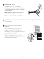
14 Retire la cubierta del sistema de caldera o
calefacción
Abra la cubierta del sistema de calefacción o
refrigeración para ubicar la tarjeta de control.
Debería ver las mismas etiquetas de terminales que
se encuentran en el termostato.
Nota: Es posible que necesite desatornillar la
cubierta. La tarjeta de control puede encontrarse en
la parte superior o en la inferior.
G
C
R
W
Y

12
16
15
17
Conecte el cable sin usar a la terminal C
Nota: Si ya hay cables conectados a la terminal C,
asegúrese que permanezcan así luego de conectar
este cable.
Encuentre el otro extremo del cable sin usar
Ubique el conjunto de cables que son iguales a los
del termostato.
El cable sin usar debe ser del mismo color que el
que se encuentra cerca del termostato existente.
Consulte el paso 13 para verificar qué color anotó.
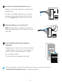
Cierre la cubierta del sistema de caldera o
calefacción
Asegúrese que la cubierta se encuentre cerrada por
completo. Algunos sistemas no se encenderán si la
cubierta no se encuentra cerrada por completo.
Ha conectado el cable C.
NO necesitará usar un adaptador del cable C.
G
C
R
W
Y
G
C
R
W
Y
-
Vuelva a la pared en la que está instalando el termostato y continúe con la sección
“Instalación del termostato nuevo”, en la página siguiente.

13
Instalación del termostato nuevo
Necesitará lo siguiente: Nivel, lápiz, taladro y una broca
Termostato Tornillos Placa
de pared
UWP
ParedAnclajes

14
18
19
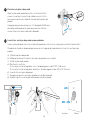
Posicione la placa de pared
Abra la placa de pared provista con el termostato
nuevo. Inserte el conjunto de cables por el orificio
que se encuentra en la parte trasera de la placa de
pared.
Asegúrese que haya al menos 1/4 pulgada (6.35mm)
de cada cable expuesto para que sea más fácil la
inserción en las terminales de cableado.
Inserte los anclajes de pared recomendados
Se recomienda que use los anclajes de pared provistos en la caja para montar el termostato.
Puede usar la placa de pared para marcar los lugares donde desea colocar los anclajes de
pared.
a) Nivele la placa de pared
b) Marque la ubicación de los anclajes de pared con un lápiz
c) Quite la placa de pared
d) Perfore los orificios.
Si su caja contiene taquetes rojos, taladre agujeros de 7/32” (5.6 mm).
Si su caja contiene taquetes amarillos, taladre agujeros de 3/16” (4.76 mm).
e) Inserte los anclajes de pared
f) Asegúrese que los anclajes queden al ras de la pared
g) Vuelva a posicionar la placa de pared sobre la pared
-
UWP
Anclajes Pared

15
1. Asegúrese que
el interruptor
R derecho se
encuentre
hacia arriba.
1. Coloque el
interruptor R
derecho hacia
abajo.
20 Determine la posición correcta del interruptor R e inserte el/los cable/s R
Establezca el interruptor R hacia arriba o abajo según las notas de cableado del paso 8. Inserte
los cables por los orificios interiores de las terminales de la placa de pared. Las pestañas se
mantendrán abajo una vez que se inserten los cables.
Si tiene 1 cable R (R, RC, RH):
Si tiene 2 cables R (R, RC, RH):
2. Inserte el
cable R (R,
Rh o Rc) en
la terminal R.
2. Inserte el
cable Rc en la
terminal Rc.
3. Inserte el cable
R o Rh en la
terminal R.
O

16
21 Conecte el resto de los cables del paso 8
Empuje las pestañas para colocar los cables
en los orificios interiores de sus terminales
correspondientes en la placa de pared (un cable por
terminal) hasta que estén firmes en su lugar.
Tire suavemente de los cables para verificar que
estén asegurados.
Sugerencia: Si necesita volver a liberar los cables,
empuje las pestañas de la terminal hacia los lados de
la placa de pared.
El cableado es solo a modo de
ejemplo; el cableado real puede
variar.
22
23
Cierre la puerta y monte la placa de pared
Monte la placa de pared con los tornillos provistos.
Instale los tres tornillos para lograr un ajuste seguro
en la pared.
Sugerencia: Antes de ajustar los tornillos, use un
nivel para asegurarse que la placa de pared esté
nivelada.
Fije el termostato
Alinee el termostato con la placa de
pared y empújelo con firmeza para
ajustarlo en su lugar.

17
24
25
Vuelva a conectar el suministro de energía
Encienda el interruptor que controla su sistema de
calefacción y refrigeración.
Complete la instalación del termostato
Quite la película protectora y confirme que en
el termostato aparezca la leyenda “Welcome!”
(Bienvenido).
Si no aparece la leyenda, visite Honeywell Home.
com/support o llame al 18006333991 para
obtener más ayuda.
Vuelva a la caja de disyuntores del circuito.
Diríjase nuevamente al termostato.
OFF
ON
O
Caja de disyuntores
Interruptor
Welcome!

18
Aprovechar al máximo el T9 Smart Thermostat
Priorice las habitaciones (requiere el accesorio sensor inalámbrico para habitación)
Priorice una o varias habitaciones específicas, o permita que la comodidad lo siga mediante la
detección de movimiento incorporada.
Control sobre la marcha
Ajuste el termostato desde cualquier lugar usando su tablet o teléfono inteligente.
Ahorre energía
Con la geovalla, puede ahorrar la parte más costosa de su factura de energía mientras se encuentra
fuera del hogar.
Instalación simple
El termostato se programa automáticamente. Solo responda algunas preguntas sencillas y estará
listo y preparado para comenzar a funcionar de inmediato.
Rango de cobertura para todo el hogar (requiere el accesorio sensor inalámbrico para habitación)
Con un rango de cobertura de hasta 60 metros (200 pies)*, 20 sensores con detección de
temperatura, humedad y ocupación pueden conectarse al termostato desde la totalidad de su hogar.
*El rango puede variar en función de la construcción de su hogar, la interferencia inalámbrica y otros
factores.
Sepa que su hogar está seguro
Configure alertas personalizadas en su dispositivo móvil, por ejemplo, cuando el sótano está tan frío
que una tubería podría reventar o si la habitación del bebé está demasiado calurosa.

19
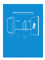
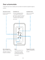
Usar su termostato
La pantalla se activará cuando presione el área central de la temperatura que se
muestra.
74
2
18%
Temperatura interior
Muestra la temperatura
interior actual.
Ajustar temperatura
Toque las flechas arriba y
abajo para configurar su
temperatura deseada.
Prioridad actual
Muestra el tipo de prioridad y
la cantidad de habitaciones
priorizadas. Expanda el alcance
de su termostato con sensores
inalámbricos para habitación
adicionales.
Menú
Contiene características
como modo, ventilador,
cronograma, prioridad y
otras configuraciones de
termostato.
Humedad interior
Muestra la humedad
interior actual.
Temperatura deseada
Muestra la temperatura
deseada.

20
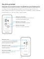
Uso de la prioridad
(requiere el accesorio sensor inalámbrico para habitación)
La configuración de prioridades genera una temperatura promedio en el hogar tomando como
referencia habitaciones específicas. Esto le permite priorizar la comodidad en los espacios que desee.
En la pantalla de “Inicio”, seleccione “Menú” y, luego, “Prioridad”.
72 72
72 72
72 72
72 72
Habitaciones activas
Las habitaciones con movimiento detectado se
seleccionan automáticamente para crear una
temperatura promedio en el hogar.
Habitación sin actividad
No se detecta movimiento. No contribuirá a la
temperatura promedio.
Habitación con actividad
Se detecta movimiento. Contribuirá a la
temperatura promedio.
Habitaciones seleccionadas
Las habitaciones que seleccione manualmente crean
una temperatura promedio en el hogar.
Habitación no seleccionada
No contribuirá a la temperatura promedio.
Habitación seleccionada
Contribuirá a la temperatura promedio.

21
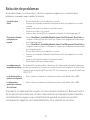
Solución de problemas
Si tiene dificultades con el termostato, intente las siguientes sugerencias. La mayoría de los
problemas se puede corregir rápida y fácilmente.
La pantalla está en
blanco
• Revise el disyuntor del circuito y restablezca si es necesario.
• Asegúrese que el interruptor de alimentación del sistema de calefacción y refrigeración se encuentre
encendido.
• Asegúrese que la puerta de la caldera se encuentre bien cerrada.
• Asegúrese que el cable C esté conectado.
• Asegúrese de que el puente R/Rc esté configurado correctamente. Consulte la página page 15.
El sistema de calefacción
y refrigeración no
responde
• Presione Menu (Menú) > System Mode (Modo del sistema) > Heat (Calefacción) > Done (Listo) para
configurar el sistema en el modo Heat (Calefacción). Asegúrese que la temperatura deseada sea mayor
que la temperatura interior.
• Presione Menu (Menú) > System Mode (Modo del sistema) > Cool (Refrigeración) > Done (Listo) para
configurar el sistema en el modo Cool (Refrigeración). Asegúrese que la temperatura deseada sea menor
que la temperatura interior.
• Revise el disyuntor del circuito y restablezca si es necesario.
• Asegúrese que el interruptor de alimentación del sistema de calefacción y refrigeración se encuentre
encendido.
• Asegúrese que la puerta de la caldera se encuentre bien cerrada.
• Espere 5 minutos hasta que el sistema responda.
Las configuraciones de
temperatura no cambian
En este termostato, se pueden ajustar las configuraciones de los límites mínimos y máximos de temperatura
de calefacción y refrigeración. Si este ajuste no se realizó al momento de la configuración, la calefacción tiene
un rango de ajuste de entre 40 y 90 °F (entre 4,5 y 32,0 °C) y la refrigeración, uno de entre 50 y 99 °F (entre
10,0 y 37,0 °C).
La calefacción auxiliar se
ejecuta en la refrigeración
• Para los sistemas con bomba de calor, verifique que no haya un cable adherido a W en el UWP.
La refrigeración se
ejecuta con la activación
de la calefacción
• Para los sistemas con bomba de calor, verifique que no haya un cable adherido a W en el UWP.
El producto no debe desecharse junto con otros residuos domésticos. Busque el centro
de recolección autorizado más cercano o empresas de reciclaje autorizadas. Desechar
correctamente los equipos cuya vida útil terminó ayudará a prevenir las posibles
consecuencias negativas en el medioambiente y en la salud de las personas.

22
POLIZA DE GARANTIA
IMPORTADO EN MEXICO POR:
INSTROMET MEXICANA S DE R L DE C V
Avenida Insurgentes 2453, Piso 6,
Tizapan, Alvaro Obregon,
Ciudad de Mexico, CP 01090
Telefono: 01 (55) 800 00423
Instromet Mexicana S. de R.L. de C.V. garantiza que éste producto está libre de defectos en su mano de obra y materiales contra cualquier defecto de fabricación y
funcionamiento, bajo uso normal, por el término de 2 años a partir de la fecha de la compra por el consumidor. Si se determina que el producto esta defectuoso o presenta algún
funcionamiento erróneo, Instromet Mexicana S. de R.L. de C.V. deberá reparar o reemplazar (a opción de Instromet) el producto bajo las siguientes condiciones:
1. Regresar el producto y la póliza de garantía, acompañado de la factura de venta o algún otro comprobante de compra fechado al establecimiento donde se realizó la compra,
o a la siguiente dirección. En la cual también tendrá la información para obtener las partes, componentes, consumibles y accesorios del producto: Av. Salvador Nava Martinez
3125, Col. Colinas del Parque. SanLuis Potosi, SLP Mexico 78294.
2. O puedes llamar al centro de atención al cliente al 018000835925 para México (ver teléfonos para otros países) donde se determinará si el producto debe regresarse o
si se enviará un reemplazo del producto al consumidor sin costo alguno cubriendolos gastos que se deriven del cumplimiento de la presente garantía incluyendo los gastos
de transporte. No es necesario pedir piezas ni accesorios. El producto será reemplazado bajo esta garantía.
Nota: Esta garantía no cubre gastos de mano de obra por re-instalación. No ampara el reemplazo de la pieza si el defecto ocurre por daño causado por el consumidor o desgaste
normal
La única responsabilidad de Instromet será reparar o reemplazar el producto dentro de los términos establecidos más arriba. Instromet Mexicana S. de R.L. de C.V. no será
responsable de ninguna pérdida o daño de ningún tipo, incluidos los daños incidentales o derivados, que resulten, de manera directa o indirecta, del incumplimiento de la
garantía, expresa o implícita, o de cualquier otra falla de este producto.
Esta garantía es la única garantía expresa que Instromet Mexicana S. de R.L. de C.V. ofrece respecto de este producto. La duración de cualquier garantía implícita, incluidas las
garantías de comerciabilidad e idoneidad para un fin específico, se limita por el presente a la duración de dos años de esta garantía.
Esta garantía no es válida en los siguientes casos:
1. Cuando el producto haya sido utilizado en condiciones distintas a las normales (aquellas para las que está destinado)
2. Cuando el producto no ha sido operado de acuerdo con el instructivo de uso e instalación proporcionado.
3. Cuando el producto ha sido alterado o reparado por personas no autorizadas por Instromet Mexicana S. de R.L. de C.V.
Datos del producto:
Marca: _________________ Modelo: _________________ Número de serie: __________________________________________
Nombre del consumidor: _______________________________________________________________________________________________________
Dirección (calle y número): _____________________________________________________________________________________________________
Delegación o municipio: _______________________________________________________________________________________________________
Ciudad, estado y código postal: _________________________________________________________________________________________________
Sello del establecimiento y fecha de compra

23
La operación de este equipo está sujeta a las siguientes dos condiciones: (1) es posible que este equipo o dispositivo no cause
interferencia perjudicial y (2) este equipo o dispositivo debe aceptar cualquier interferencia, incluyendo la que pueda causar su
operación no deseada.
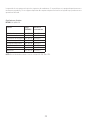
Clasificaciones eléctricas
ENTRADA: 24 V~@60 Hz, 0.2 A
Terminal Voltaje
(50/60 Hz)
Corriente en
funcionamiento
W Calefacción 20 a 30 V CA 0.02 a 1.0 A
W2 Calefacción (Auxiliar) 20 a 30 V CA 0.02 a 1.0 A
E Calefacción de emergencia 20 a 30 V CA 0.02 a 0.5 A
Y Etapa de compresión 1 20 a 30 V CA 0.02 a 1.0 A
Y2 Etapa de compresión 2 20 a 30 V CA 0.02 a 1.0 A
G Ventilador 20 a 30 V CA 0.02 a 0.5 A
O/B Conversión 20 a 30 V CA 0.02 a 0.5 A
L/A Entrada 20 a 30 V CA 0.02 a 0.5 A
NOTA: No está destinado a utilizarse con los sistemas MV 250, 500 o 750.

www.resideo.com
© 2020 Resideo Technologies, Inc. All rights reserved.
The Honeywell Home trademark is used under license from Honeywell International, Inc.
This product is manufactured by Resideo Technologies, Inc. and its affiliates.
Todos los derechos reservados. La marca comercial Honeywell Home se utiliza bajo licencia
de Honeywell International, Inc.
Este producto es fabricado por Resideo Technologies, Inc. y sus afiliados.
33-00525ES-01
Resideo Technologies Inc.
1985 Douglas Drive North, Golden Valley, MN 55422
18006333991
3300525ES01 M.S. Rev. 0320 | Impreso en Estados Unidos
Código de configuración de
HomeKit™ de Apple®
El T9 Pro Smart es compatible con Apple HomeKit.
Cuando se lo indique la aplicación Honeywell Home,
escanee el código de la contraportada de la guía incluida
con su termostato inteligente T9.
-
 1
1
-
 2
2
-
 3
3
-
 4
4
-
 5
5
-
 6
6
-
 7
7
-
 8
8
-
 9
9
-
 10
10
-
 11
11
-
 12
12
-
 13
13
-
 14
14
-
 15
15
-
 16
16
-
 17
17
-
 18
18
-
 19
19
-
 20
20
-
 21
21
-
 22
22
-
 23
23
-
 24
24
-
 25
25
-
 26
26
-
 27
27
-
 28
28
-
 29
29
-
 30
30
-
 31
31
-
 32
32
-
 33
33
-
 34
34
-
 35
35
-
 36
36
-
 37
37
-
 38
38
-
 39
39
-
 40
40
-
 41
41
-
 42
42
-
 43
43
-
 44
44
-
 45
45
-
 46
46
-
 47
47
-
 48
48


Honeywell RCHT9610WFSW2003/U Guía de instalación
- Tipo
- Guía de instalación
- Este manual también es adecuado para
en otros idiomas
Artículos relacionados
-
Honeywell RTH8800WF2022/U Instrucciones de operación
-
Honeywell RCHT8610WF Guía de instalación
-
-
-
Honeywell THX321WFS2001W Guía del usuario
-
Honeywell TH6210U2001 El manual del propietario
-
-
Otros documentos
-
 Honeywell Home RTH8800WF2022/U Guía de instalación
-
 Honeywell Home RTH9585WF1004/U Guía del usuario
-
 Honeywell Home THX321WFS2001W Guía de instalación
-
 Honeywell Home CWIREADPTR4001 Guía de instalación
-
 Honeywell Home RET97E5D1005/U Guía de inicio rápido
-
Honeywell Home T3 Pro Installation Instructions Manual
-
 Honeywell Home THP2400A1027 Cover Plate Guía de instalación
-
resideo PROSIXLCDKP-EU Guía del usuario


